EP1309076A2 - Supply circuit for electronic unit - Google Patents
Supply circuit for electronic unit Download PDFInfo
- Publication number
- EP1309076A2 EP1309076A2 EP02023480A EP02023480A EP1309076A2 EP 1309076 A2 EP1309076 A2 EP 1309076A2 EP 02023480 A EP02023480 A EP 02023480A EP 02023480 A EP02023480 A EP 02023480A EP 1309076 A2 EP1309076 A2 EP 1309076A2
- Authority
- EP
- European Patent Office
- Prior art keywords
- power supply
- energy
- electronic assembly
- capacitive
- switching element
- Prior art date
- Legal status (The legal status is an assumption and is not a legal conclusion. Google has not performed a legal analysis and makes no representation as to the accuracy of the status listed.)
- Withdrawn
Links
Images
Classifications
-
- H—ELECTRICITY
- H02—GENERATION; CONVERSION OR DISTRIBUTION OF ELECTRIC POWER
- H02M—APPARATUS FOR CONVERSION BETWEEN AC AND AC, BETWEEN AC AND DC, OR BETWEEN DC AND DC, AND FOR USE WITH MAINS OR SIMILAR POWER SUPPLY SYSTEMS; CONVERSION OF DC OR AC INPUT POWER INTO SURGE OUTPUT POWER; CONTROL OR REGULATION THEREOF
- H02M7/00—Conversion of ac power input into dc power output; Conversion of dc power input into ac power output
- H02M7/02—Conversion of ac power input into dc power output without possibility of reversal
- H02M7/04—Conversion of ac power input into dc power output without possibility of reversal by static converters
- H02M7/12—Conversion of ac power input into dc power output without possibility of reversal by static converters using discharge tubes with control electrode or semiconductor devices with control electrode
-
- H—ELECTRICITY
- H02—GENERATION; CONVERSION OR DISTRIBUTION OF ELECTRIC POWER
- H02M—APPARATUS FOR CONVERSION BETWEEN AC AND AC, BETWEEN AC AND DC, OR BETWEEN DC AND DC, AND FOR USE WITH MAINS OR SIMILAR POWER SUPPLY SYSTEMS; CONVERSION OF DC OR AC INPUT POWER INTO SURGE OUTPUT POWER; CONTROL OR REGULATION THEREOF
- H02M7/00—Conversion of ac power input into dc power output; Conversion of dc power input into ac power output
- H02M7/02—Conversion of ac power input into dc power output without possibility of reversal
- H02M7/04—Conversion of ac power input into dc power output without possibility of reversal by static converters
- H02M7/05—Capacitor coupled rectifiers
Definitions
- the invention relates to a capacitive power supply for an electronic assembly, a electronic assembly, in particular for controlling refrigerators and / or freezers, with controls to control a power supply and a system a capacitive power supply and an electronic assembly, in particular for Control of refrigerators and / or freezers.
- Capacitive capacitors are often used to supply power to electronic assemblies Power supplies are used that provide an inexpensive supply of small services enable. Known power supplies are always on the maximum load case, i.e. Energy requirements of the electronics designed. Is the maximum load is not given, the energy is nevertheless taken from the network due to the circuitry and converted into heat in the power supply. This has an unnecessary energy consumption result and can, in particular z. B. when used for cooling and / or Freezers, lead to undesirable heating.
- the object of the present invention is a power supply, an electronic assembly or a system consisting of a power supply and an electronic assembly specify with which unnecessary energy consumption can be avoided.
- a capacitive power supply unit has two or more power supply paths which are each equipped with a capacitive element.
- the Energy supply paths are used to provide different amounts of energy for different energy requirements caused by the electronic assembly.
- the power supply unit according to the invention is therefore equipped for various load cases. Depending on the energy requirements of the electronics, the z. B. by additional operations may be necessary, for. B. uses multiple power supply paths to transfer a larger amount of energy from the power supply to the electronic To deliver assembly. The amount of energy delivered to the electronic assembly can therefore be optimally adapted to the current energy requirements.
- the Power supply unit is therefore not always operated with the maximum power required for the maximum load case is determined by the electronic assembly. unnecessary Energy consumption and unnecessary heat generation are thus avoided.
- the different energy supply paths can be adjusted accordingly Switching elements be equipped, the z. B. of the electronic assembly zuoder be switched off.
- the energy supply paths can be used for delivery different amounts of energy can be designed so that by selecting the appropriate Power supply path is the amount of energy that is determined the electronic assembly is delivered.
- At least one of the energy supply paths two capacitive elements connected in series. At least one of these capacitive elements can be connected in parallel Switching element are short-circuited. This creates a different energy supply path.
- By bridging the corresponding capacitive element the energy provided to the electronic assembly increases because instead of connecting two capacitive elements in series, only one capacitive element Element is effective. Even circuits designed in this way with one another in series switched capacitive elements can be provided several times to To increase flexibility of the power supply.
- One or more energy supply paths can also be connected in series capacitive elements, at least one of which can be bridged, and other power supply paths where a switching element is in series to one capacitive element is provided to be realized in a power supply.
- Another electrical consumer is provided, which is arranged in a circuit is that to the capacitive element of an energy supply path in Series-connected switching element includes, so that when connecting this power supply path with the help of the corresponding switching element the additional consumer is powered when the power supply is in operation.
- a Switching element can z. B. lighting simultaneously with the energy supply path connected to the electronic module to increase the energy supply become.
- the increased energy requirement of the electronic assembly which is triggered by the fact that a request to operate an additional Consumer is to be processed by the electronic assembly, to make available by switching the switching element, the switching on of the corresponding additional electrical consumer.
- the power supply unit advantageously has a buffer element that contains an amount of energy can build and store that for switching at least one switching element suitable is.
- This buffer element is like this with the corresponding switching element connected that it the built upon a signal from the electronic assembly or stored energy to actuate the switching element on this emits. If a request to provide an additional power supply path there is no additional with such a buffer element Energy required to switch the switching element.
- An electronic assembly with the features of claim 7 has control elements on, with the help of the switching elements of a power supply according to the invention can be controlled.
- the control elements are designed in such a way that when the energy requirement of the electronic assembly changes, a signal is given that for switching the switching element or the switching elements suitable is.
- a buffer element can be provided in such an electronic assembly be suitable for building and storing an amount of energy that is suitable for switching at least one of the switching elements of the power supply.
- the invention also includes an electronic assembly system and a capacitive power supply unit, in which the electronic assembly has one or more Includes switching elements that can be connected to the power supply such that they Can switch power supply paths of the power supply on or off.
- the switching elements within the electronic assembly provided and need not be implemented in the power supply.
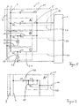
- FIG. 1 shows the circuit diagram of a capacitive power supply unit 3 according to the invention in operation with an electronic component 1.
- 7 and 9 indicate supply lines the power supply unit, via whose connections N, L an external power supply is connected becomes.
- An electrical connection 12 is used to connect to the electronic assembly 1.
- 11 denotes a permanently switched energy supply path with a capacitive element C1.
- 13 denotes a second one Power supply path with a capacitive element C2 and one in Series switched switching element S1.
- the control of this switching element S1 is known from the electronic assembly 1 via the signal line 27 in a conventional manner Way.
- 15 denotes a third energy supply path a capacitive element C3.
- a switching element S2 is connected in series for this purpose, which is connected to the electronic assembly via a signal line 29.
- 19 is an example of a light bulb that is connected to the supply lines via a circuit 17 7 and 9 is connected and also via the switching element S2 can be switched.
- 21 denotes a fourth power supply path with a capacitive element C4.
- a switching element S3 is connected in series, via a signal line 31 is connected to the electronic assembly 1.
- 25 denotes a Motor relay M, which is in a circuit 23 with the supply lines of the Power supply 7 and 9 is connected. The circuit is such that with the switching element S3 also the power supply of the motor relay can be controlled.
- Figure 1 The arrangement of Figure 1 is suitable for. B. for the energy supply of an electronic Module 1, which is used to control a refrigerator and / or freezer is used.
- the energy required to switch on the switching element S1 can built up over a longer period in a buffer element, not shown in order to keep energy consumption to a minimum during normal operation.
- the buffer element can either be located in the electronic assembly 1 or in the power supply 3 itself.
- the buffer element is in the electronic Module 1, the energy for switching the respective switching element provided. Otherwise the signal lines are used 27, 29, 31 for transmission of the signal to a buffer element for release the energy to the respective switching element.
- Section B shows a corresponding arrangement in connection z. B. with the Interior lighting and / or the temperature display of a refrigerator or freezer.
- the in the z. B. provided in the electronic assembly 1 buffer element built-up buffer energy is sufficient to switch element S2 for interior lighting 19 turn on. This will both the lighting and the additional power supply path 15 connected.
- the electronic assembly 1 therefore has sufficient power to control the switching state of the switching element S2 to maintain the interior lighting 19 and possibly also a temperature display to provide with.
- Section C shows a corresponding arrangement in connection with the Compressor of a refrigerator and / or freezer.
- Figure 2 shows an alternative structure for the one in Figure 1 with the dashed Part 5 designated frame, the dashed frame 41 of the Figure 2 corresponds to the dashed frame 5 of Figure 1.
- Figure 2 shows another Arrangement for realizing several energy supply paths. 43 designated a first energy supply path with the capacitive elements C5 and C6. 45 denotes a circuit connected in parallel with a switching element S4, by means of which the capacitor C6 can be bridged. Again only the arrangement of the two possible energy supply paths is for a simplified representation of Figure 2 summarized with A * dash-dotted lines.
- the switch S4 is therefore open in normal operation. Rises for some reason the energy requirement of the electronic assembly 1, it sends this over the signal line 47 a signal to the switch S4 so that it can be used if necessary of the energy stored in a buffer element, not shown, closes.
- the Energy supply is therefore only influenced by the capacitor C5 and it creates a second power supply path 43, 45 bypassing the capacitor C6. In this way, a higher energy is made available and the increased energy requirement of the electronic assembly 1 is taken into account.
- Section A * already provides two different possible energy supply paths available and therefore enables the realization of the invention.
- Corresponding sections B and C can of course also be provided be one or more sections A * to provide flexible power supply design to ensure the electronic assembly 1.
- the capacitors C1, C2, C3, C4 can be arranged externally or on one appropriate electronics.
- switching elements S1, S2, S3 or S4 arranged in the power supply unit 3 can also existing switching elements on the electronic assembly 1 used for connecting an additional power supply path become.
- the electronic assembly 1 only needs the energy for switching on of the respective switching element.
- the energy required to turn on is in turn in a buffer element, which is located in the electronic assembly 1, so that the To keep energy consumption as low as possible in normal operation.
Abstract
Description
Die Erfindung betrifft ein kapazitives Netzteil für eine elektronische Baugruppe, eine elektronische Baugruppe, insbesondere zur Steuerung von Kühl- und/oder Gefriergeräten, mit Steuerelementen zur Steuerung eines Netzteiles und ein System aus einem kapazitiven Netzteil und einer elektronischen Baugruppe, insbesondere zur Steuerung von Kühl- und/oder Gefriergeräten.The invention relates to a capacitive power supply for an electronic assembly, a electronic assembly, in particular for controlling refrigerators and / or freezers, with controls to control a power supply and a system a capacitive power supply and an electronic assembly, in particular for Control of refrigerators and / or freezers.
Zur Energieversorgung von elektronischen Baugruppen werden vielfach kapazitive Netzteile eingesetzt, die eine kostengünstige Versorgung mit kleinen Leistungen ermöglichen. Bekannte Netzteile sind dabei immer auf den maximalen Belastungsfall, d.h. Energiebedarf der Elektronik ausgelegt. Ist der maximale Belastungsfall nicht gegeben, so wird die Energie schaltungsbedingt dem Netz dennoch entnommen und im Netzteil in Wärme umgewandelt. Dies hat einen unnötigen Energieverbrauch zur Folge und kann, im speziellen z. B. bei der Anwendung für Kühlund/oder Gefriergeräten, zu einer unerwünschten Erwärmung führen. Capacitive capacitors are often used to supply power to electronic assemblies Power supplies are used that provide an inexpensive supply of small services enable. Known power supplies are always on the maximum load case, i.e. Energy requirements of the electronics designed. Is the maximum load is not given, the energy is nevertheless taken from the network due to the circuitry and converted into heat in the power supply. This has an unnecessary energy consumption result and can, in particular z. B. when used for cooling and / or Freezers, lead to undesirable heating.
Aufgabe der vorliegenden Erfindung ist es, ein Netzteil, eine elektronische Baugruppe bzw. ein System aus einem Netzteil und einer elektronischen Baugruppe anzugeben, mit denen ein unnötiger Energieverbrauch vermieden werden kann.The object of the present invention is a power supply, an electronic assembly or a system consisting of a power supply and an electronic assembly specify with which unnecessary energy consumption can be avoided.
Diese Aufgabe wird erfindungsgemäß mit einem Netzteil mit den Merkmalen des
Anspruches 1, einer elektronischen Baugruppe mit den Merkmalen des Anspruches
7 bzw. einem System mit den Merkmalen des Anspruches 9 oder 10 gelöst.This object is achieved with a power supply unit with the features of
Ein erfindungsgemäßes kapazitives Netzteil weist zwei oder mehr Energieversorgungspfade auf, die jeweils mit einem kapazitiven Element ausgestattet sind. Die Energieversorgungspfade dienen zur Bereitstellung unterschiedlicher Energiemengen für unterschiedliche, durch die elektronische Baugruppe hervorgerufene Energiebedarfszustände.A capacitive power supply unit according to the invention has two or more power supply paths which are each equipped with a capacitive element. The Energy supply paths are used to provide different amounts of energy for different energy requirements caused by the electronic assembly.
Das erfindungsgemäße Netzteil ist also für verschiedene Belastungsfälle ausgerüstet. Je nach Energiebedarf der Elektronik, der z. B. durch zusätzliche Operationen notwendig werden kann, können z. B. mehrere Energieversorgungspfade verwendet werden, um eine größere Energiemenge vom Netzteil an die elektronische Baugruppe liefern zu können. Die an die elektronische Baugruppe gelieferte Energiemenge kann also optimal an den aktuellen Energiebedarf angepaßt werden. Das Netzteil wird also nicht immer mit der maximalen Leistung betrieben, die für den maximalen Belastungsfall durch die elektronische Baugruppe bestimmt ist. Unnötiger Energieverbrauch und unnötige Wärmeerzeugung werden also vermieden.The power supply unit according to the invention is therefore equipped for various load cases. Depending on the energy requirements of the electronics, the z. B. by additional operations may be necessary, for. B. uses multiple power supply paths to transfer a larger amount of energy from the power supply to the electronic To deliver assembly. The amount of energy delivered to the electronic assembly can therefore be optimally adapted to the current energy requirements. The Power supply unit is therefore not always operated with the maximum power required for the maximum load case is determined by the electronic assembly. unnecessary Energy consumption and unnecessary heat generation are thus avoided.
Die unterschiedlichen Energieversorgungspfade können mit entsprechenden Schaltelementen ausgerüstet sein, die z. B. von der elektronischen Baugruppe zuoder abgeschaltet werden. Die Energieversorgungspfade können zur Lieferung verschieden hoher Energiemengen ausgelegt sein, so daß durch Auswahl des entsprechenden Energieversorgungspfades die Energiemenge bestimmt wird, die an die elektronische Baugruppe geliefert wird. The different energy supply paths can be adjusted accordingly Switching elements be equipped, the z. B. of the electronic assembly zuoder be switched off. The energy supply paths can be used for delivery different amounts of energy can be designed so that by selecting the appropriate Power supply path is the amount of energy that is determined the electronic assembly is delivered.
Besonders vorteilhaft ist es, wenn die für die Grundlast benötigte Energie, welche immer erforderlich ist, ein permanent geschalteter Energieversorgungspfad vorgesehen ist. Wird von der Elektronik aus irgendeinem Grund mehr Energie benötigt, so wird ein weiterer Energieversorgungspfad mit einem in Serie zu dessen kapazitivem Element geschalteten Schaltelement hinzugeschaltet. Auf diese Weise sind zwei Energieversorgungspfade zugeschaltet und die an die elektronische Baugruppe gelieferte Energie ist höher. Auf diese Weise können selbstverständlich je nach Bedarf auch mehrere Energieversorgungspfade hinzugeschaltet werden.It is particularly advantageous if the energy required for the base load a permanently switched power supply path is always required is. If for some reason electronics needs more energy, thus another energy supply path with one in series becomes its capacitive one Element switched switching element switched on. That way two power supply paths connected and the to the electronic assembly delivered energy is higher. This way, of course, depending on If necessary, several energy supply paths can also be connected.
Bei einer anderen vorteilhaften Ausgestaltung weist zumindest einer der Energieversorgungspfade zwei in Serie geschaltete kapazitive Elemente auf. Zumindest eines dieser kapazitiven Elemente kann mit Hilfe eines parallel geschalteten Schaltelementes kurzgeschlossen werden. So entsteht ein anderer Energieversorgungspfad. Durch die Überbrückung des entsprechenden kapazitiven Elementes erhöht sich die der elektronischen Baugruppe zur Verfügung gestellte Energie, da anstatt der Reihenschaltung zweier kapazitiver Elemente nur noch ein kapazitives Element wirksam ist. Auch derartig ausgestaltete Schaltungen mit in Serie zueinander geschalteten kapazitiven Elementen können mehrfach vorgesehen sein, um die Flexibilität des Netzteiles zu erhöhen.In another advantageous embodiment, at least one of the energy supply paths two capacitive elements connected in series. At least one of these capacitive elements can be connected in parallel Switching element are short-circuited. This creates a different energy supply path. By bridging the corresponding capacitive element the energy provided to the electronic assembly increases because instead of connecting two capacitive elements in series, only one capacitive element Element is effective. Even circuits designed in this way with one another in series switched capacitive elements can be provided several times to To increase flexibility of the power supply.
Ebenso können ein oder mehr Energieversorgungspfade mit in Serie geschalteten kapazitiven Elementen, von denen zumindest jeweils eines überbrückbar ist, und andere Energieversorgungspfade, bei denen ein Schaltelement in Serie zu einen kapazitiven Element vorgesehen ist, in einem Netzteil realisiert werden.One or more energy supply paths can also be connected in series capacitive elements, at least one of which can be bridged, and other power supply paths where a switching element is in series to one capacitive element is provided to be realized in a power supply.
Bei einer vorteilhaften Weiterbildung ist zusätzlich zu der elektronischen Baugruppe ein weiterer elektrischer Verbraucher vorgesehen, der in einem Stromkreis angeordnet ist, der das zu dem kapazitiven Element eines Energieversorgungspfades in Serie geschaltete Schaltelement umfaßt, so daß beim Zuschalten dieses Energieversorgungspfades mit Hilfe des entsprechenden Schaltelementes der weitere Verbraucher mit Energie versorgt wird, wenn das Netzteil in Betrieb ist. Mit einem Schaltelement kann dazu z. B. eine Beleuchtung gleichzeitig mit dem Energieversorgungspfad zur Erhöhung der Energiezufuhr an die elektronische Baugruppe geschaltet werden. Andererseits ist es mit einer solchen vorteilhaften Schaltungsanordnung möglich, z. B. den erhöhten Energiebedarf der elektronischen Baugruppe, der gerade dadurch ausgelöst wird, daß eine Anforderung zum Betreiben eines zusätzlichen Verbrauchers durch die elektronische Baugruppe bearbeitet werden soll, durch Schalten des Schaltelementes zur Verfügung zu stellen, das auch das Zuschalten des entsprechenden zusätzlichen elektrischen Verbrauchers bewirkt.In an advantageous development, in addition to the electronic assembly Another electrical consumer is provided, which is arranged in a circuit is that to the capacitive element of an energy supply path in Series-connected switching element includes, so that when connecting this power supply path with the help of the corresponding switching element the additional consumer is powered when the power supply is in operation. With a Switching element can z. B. lighting simultaneously with the energy supply path connected to the electronic module to increase the energy supply become. On the other hand, it is with such an advantageous circuit arrangement possible, e.g. B. the increased energy requirement of the electronic assembly, which is triggered by the fact that a request to operate an additional Consumer is to be processed by the electronic assembly, to make available by switching the switching element, the switching on of the corresponding additional electrical consumer.
Vorteilhafterweise weist das Netzteil ein Pufferelement auf, das eine Energiemenge aufbauen und speichern kann, die zum Schalten zumindest eines Schaltelementes geeignet ist. Dieses Pufferelement ist mit dem entsprechenden Schaltelement derart verbunden, daß es auf ein Signal der elektronischen Baugruppe hin die aufgebaute bzw. gespeicherte Energie zur Betätigung des Schaltelementes an dieses abgibt. Wenn eine Anforderung zum Bereitstellen eines zusätzlichen Energieversorgungspfades vorliegt, ist mit einem solchen Pufferelement keine zusätzliche Energie zum Schalten des Schaltelementes notwendig.The power supply unit advantageously has a buffer element that contains an amount of energy can build and store that for switching at least one switching element suitable is. This buffer element is like this with the corresponding switching element connected that it the built upon a signal from the electronic assembly or stored energy to actuate the switching element on this emits. If a request to provide an additional power supply path there is no additional with such a buffer element Energy required to switch the switching element.
Eine elektronische Baugruppe mit den Merkmalen des Anspruches 7 weist Steuerelemente
auf, mit deren Hilfe die Schaltelemente eines erfindungsgemäßen Netzteiles
angesteuert werden können. Die Steuerelemente sind derart ausgestaltet,
daß bei sich änderndem Energiebedarf der elektronischen Baugruppe ein Signal
abgegeben wird, das zum Schalten des Schaltelementes bzw. der Schaltelemente
geeignet ist.An electronic assembly with the features of
Bei einer solchen elektronischen Baugruppe kann ein Pufferelement vorgesehen sein, das zum Aufbau und zur Speicherung einer Energiemenge geeignet ist, die zum Schalten zumindest eines der Schaltelemente des Netzteiles geeignet ist. Mit Hilfe einer solchen besonderen Ausführungsform der elektronischen Baugruppe ist die Steuerung eines Netzteiles möglich, bei dem zwar die Schaltelemente, nicht jedoch das Pufferelement im Netzteil vorgesehen sind. A buffer element can be provided in such an electronic assembly be suitable for building and storing an amount of energy that is suitable for switching at least one of the switching elements of the power supply. With With the help of such a special embodiment of the electronic assembly the control of a power supply possible, although the switching elements, not however, the buffer element is provided in the power supply.
Unabhängiger Schutz wird auch für ein System aus einer solchen erfindungsgemäßen elektronischen Baugruppe und einem erfindungsgemäßen Netzteil mit Schaltelementen zum Hinzuschalten von unterschiedlichen Energieversorgungspfaden beansprucht.Independent protection is also provided for a system based on such a system electronic assembly and a power supply according to the invention with switching elements for connecting different energy supply paths claimed.
Die Erfindung umfaßt ebenfalls ein System aus einer elektronischen Baugruppe und einem kapazitiven Netzteil, bei dem die elektronische Baugruppe ein oder mehrere Schaltelemente umfaßt, die mit dem Netzteil derart verbindbar sind, daß sie Energieversorgungspfade des Netzteiles hinzu- oder abschalten können. Bei einem solchen erfindungsgemäßen System sind also die Schaltelemente innerhalb der elektronischen Baugruppe vorgesehen und müssen nicht im Netzteil realisiert werden. Die Vorteile eines solchen Systemes mit mehreren unterschiedlichen Energieversorgungspfaden entsprechen den oben bereits geschilderten Vorteilen für ein erfindungsgemäßes kapazitives Netzteil.The invention also includes an electronic assembly system and a capacitive power supply unit, in which the electronic assembly has one or more Includes switching elements that can be connected to the power supply such that they Can switch power supply paths of the power supply on or off. At a such a system according to the invention are the switching elements within the electronic assembly provided and need not be implemented in the power supply. The advantages of such a system with several different energy supply paths correspond to the advantages for a capacitive power supply according to the invention.
Ausführungsformen der Erfindung werden anhand beiliegender Figuren im Detail erläutert. Dabei zeigt
Figur 1- einen Schaltplan eines erfindungsgemäßen kapazitiven Netzteiles im Betrieb mit einer elektronischen Baugruppe und
- Figur 2
- eine alternative Schaltung für den in
Figur 1 strichliniert eingefaßten Bereich.
- Figure 1
- a circuit diagram of a capacitive power supply according to the invention in operation with an electronic assembly and
- Figure 2
- an alternative circuit for the area bordered in Figure 1.
Figur 1 zeigt den Schaltplan eines erfindungsgemäßen kapazitiven Netzgerätes 3
im Betrieb mit einem elektronischen Bauteil 1. 7 und 9 bezeichnen Zuleitungen an
das Netzgerät, über deren Anschlüsse N, L eine externe Stromversorgung angeschlossen
wird. Eine elektrische Verbindung 12 dient der Verbindung mit der
elektronischen Baugruppe 1. 11 bezeichnet einen permanent geschalteten Energieversorgungspfad
mit einem kapazitiven Element C1. 13 bezeichnet einen zweiten
Energieversorgungspfad mit einem kapazitiven Element C2 und einem dazu in
Serie geschalteten Schaltelement S1. Die Steuerung dieses Schaltelementes S1
wird von der elektronischen Baugruppe 1 über die Signalleitung 27 in an sich bekannter
Weise ermöglicht. 15 bezeichnet einen dritten Energieversorgungspfad mit
einem kapazitiven Element C3. Dazu in Serie geschaltet ist ein Schaltelement S2,
das mit der elektronischen Baugruppe über eine Signalleitung 29 verbunden ist. 19
bezeichnet beispielhaft eine Glühbirne, die über einen Stromkreis 17 mit den Versorgungsleitungen
7 und 9 verbunden ist und ebenfalls über das Schaltelement S2
geschaltet werden kann.FIG. 1 shows the circuit diagram of a capacitive
21 bezeichnet einen vierten Energieversorgungspfad mit einem kapazitiven Element
C4. Dazu in Serie geschaltet ist ein Schaltelement S3, das über eine Signalleitung
31 mit der elektronischen Baugruppe 1 verbunden ist. 25 bezeichnet ein
Motorrelais M, das in einem Stromkreis 23 mit den Versorgungsleitungen des
Netzteiles 7 und 9 verbunden ist. Die Schaltung ist derart, daß mit dem Schaltelement
S3 auch die Stromversorgung des Motorrelais gesteuert werden kann.21 denotes a fourth power supply path with a capacitive element
C4. For this purpose, a switching element S3 is connected in series, via a
Nur zur Vereinfachung der Darstellung sind in Figur 1 einzelne Abschnitte A, B, C durch strichpunktierte Linien angedeutet, die im gezeigten Beispiel dem zweiten, dem dritten und dem vierten Energieversorgungspfad entsprechen.Individual sections A, B, C are shown in FIG. 1 only to simplify the illustration indicated by dash-dotted lines, which in the example shown are the second, correspond to the third and fourth power supply path.
Die Anordnung der Figur 1 eignet sich z. B. zur Energieversorgung einer elektronischen
Baugruppe 1, die bei der Steuerung eines Kühl- und/oder Gefriergerätes
eingesetzt wird.The arrangement of Figure 1 is suitable for. B. for the energy supply of an
Die für die Grundlast der elektronischen Baugruppe 1 benötigte Energie, welche
immer erforderlich ist, wird über den Kondensator C1 und die Leitung 11, 12 bereitgestellt.
Wird von der elektronischen Baugruppe 1 aus irgendeinem Grund mehr
Energie benötigt, so wird der Schalter S1 durch die Elektronik über die Signalleitung
27 geschlossen und somit über den Kondensator C2 ein zweiter Energieversorgungspfad
13 hinzugeschaltet. So wird der gestiegene Energiebedarf der
elektronischen Baugruppe 1 berücksichtigt. The energy required for the base load of the
Die Energie, welche zum Einschalten des Schaltelementes S1 erforderlich ist, kann
über einen längeren Zeitraum in einem nicht gezeigten Pufferelement aufgebaut
werden, um so den Energieverbrauch im Normalbetrieb minimal zu halten. Ein solches
Pufferelement kann sich entweder in der elektronischen Baugruppe 1 befinden
oder im Netzteil 3 selber. Befindet sich das Pufferelement in der elektronischen
Baugruppe 1, wird über die Signalleitung 27, 29, 31 die Energie zum Schalten des
jeweiligen Schaltelementes zur Verfügung gestellt. Ansonsten dienen die Signalleitungen
27, 29, 31 zur Übermittlung des Signales an ein Pufferelement zum Freigeben
der Energie an das jeweilige Schaltelement.The energy required to switch on the switching element S1 can
built up over a longer period in a buffer element, not shown
in order to keep energy consumption to a minimum during normal operation. Such one
The buffer element can either be located in the
Abschnitt B zeigt eine entsprechende Anordnung im Zusammenhang z. B. mit der
Innenbeleuchtung und/oder der Temperaturanzeige eines Kühl- oder Gefriergerätes.
Die in dem z. B. in der elektronischen Baugruppe 1 vorgesehenen Pufferelement
aufgebaute Pufferenergie reicht aus, um das Schaltelement S2 für die Innenbeleuchtung
19 einzuschalten. Hierdurch wird sowohl die Beleuchtung als auch der
weitere Energieversorgungspfad 15 hinzugeschaltet. Die elektronische Baugruppe
1 verfügt also über ausreichend Leistung, um den Schaltzustand des Schaltelementes
S2 der Innenbeleuchtung 19 aufrechtzuerhalten und ggf. noch eine Temperaturanzeige
mit zu versorgen.Section B shows a corresponding arrangement in connection z. B. with the
Interior lighting and / or the temperature display of a refrigerator or freezer.
The in the z. B. provided in the
Abschnitt C zeigt eine entsprechende Anordnung im Zusammenhang mit dem
Kompressor eines Kühl- und/oder Gefriergerätes. Bei einer solchen Anordnung
muß, solange der Kompressor abgeschaltet ist, lediglich die Energie, die zum Einschalten
des Kompressorschaltelementes S3 erforderlich ist, bereit gehalten werden.
Die Energie um den Zustand aufrechtzuerhalten, wird dann durch den zugeschalteten
weiteren Energieversorgungspfad 21 bereitgestellt.Section C shows a corresponding arrangement in connection with the
Compressor of a refrigerator and / or freezer. With such an arrangement
As long as the compressor is switched off, only the energy required to switch it on
of the compressor switching element S3 is required to be kept ready.
The energy to maintain the state is then switched on
another
Figur 2 zeigt einen alternativen Aufbau für den in Figur 1 mit dem gestrichelten
Rahmen 5 bezeichneten Teil, wobei der gestrichelt eingezeichnete Rahmen 41 der
Figur 2 dem gestrichelten Rahmen 5 der Figur 1 entspricht. Figur 2 zeigt eine andere
Anordnung zur Verwirklichung mehrerer Energieversorgungspfade. 43 bezeichnet
einen ersten Energieversorgungspfad mit den kapazitiven Elementen C5 und
C6. 45 bezeichnet einen parallel geschalteten Stromkreis mit einem Schaltelement
S4, mit dessen Hilfe der Kondensator C6 überbrückt werden kann. Wiederum nur
zur vereinfachten Darstellung ist die Anordnung der zwei möglichen Energieversorgungspfade
der Figur 2 mit A* strichpunktiert zusammengefaßt.Figure 2 shows an alternative structure for the one in Figure 1 with the dashed
Durch Überbrücken des Kondensators C6 mit Hilfe des Schalters S4 erhöht sich die
der elektronischen Baugruppe 1 zur Verfügung gestellte Energie, da anstatt der
Reihenschaltung von C5 und C6 nur der Kondensator C5 wirksam ist.By bridging the capacitor C6 with the help of the switch S4, the
the energy provided by the
Im Normalbetrieb ist der Schalter S4 also geöffnet. Steigt aus irgendeinem Grund
der Energiebedarf der elektronischen Baugruppe 1, so sendet diese über die Signalleitung
47 ein Signal an den Schalter S4, so daß sich dieser, ggf. unter Einsatz
der in einem nicht gezeigten Pufferelement gespeicherten Energie, schließt. Die
Energieversorgung wird also nur noch von dem Kondensator C5 beeinflußt und es
entsteht ein zweiter Energieversorgungspfad 43, 45 unter Umgehung des Kondensators
C6. Auf diese Weise wird eine höhere Energie zur Verfügung gestellt und
der gestiegene Energiebedarf der elektronischen Baugruppe 1 berücksichtigt.The switch S4 is therefore open in normal operation. Rises for some reason
the energy requirement of the
Der Abschnitt A* stellt bereits zwei unterschiedliche mögliche Energieversorgungspfade
zur Verfügung und ermöglicht daher die Verwirklichung der Erfindung.
Selbstverständlich können zusätzlich entsprechende Abschnitte B und C vorgesehen
sein oder mehrere Abschnitte A*, um eine flexible Gestaltung der Energieversorgung
der elektronischen Baugruppe 1 zu gewährleisten.Section A * already provides two different possible energy supply paths
available and therefore enables the realization of the invention.
Corresponding sections B and C can of course also be provided
be one or more sections A * to provide flexible power supply design
to ensure the
Die Kondensatoren C1, C2, C3, C4 können extern angeordnet sein oder auf einer entsprechenden Elektronik bestückt sein.The capacitors C1, C2, C3, C4 can be arranged externally or on one appropriate electronics.
Alternativ zu den im Netzteil 3 angeordneten Schaltelementen S1, S2, S3 oder S4
können auch ohnehin auf der elektronischen Baugruppe 1 vorhandene Schaltelemente
für das Hinzuschalten eines weiteren Energieversorgungspfades verwendet
werden. Die elektronische Baugruppe 1 muß hierzu lediglich die Energie zum Einschalten
des jeweiligen Schaltelementes aufbringen. Durch den dann hinzugeschalteten
Energieversorgungspfad ist der weitere Betrieb des entsprechenden
Schaltelementes gewährleistet. Die Energie, welche zum Einschalten erforderlich
ist, kann wiederum über einen längeren Zeitraum in einem Pufferelement, welches
sich in der elektronischen Baugruppe 1 befindet, aufgebaut werden, um so den
Energieverbrauch im Normalbetrieb möglichst minimal zu halten.As an alternative to the switching elements S1, S2, S3 or S4 arranged in the
Mit dem erfindungsgemäßen kapazitiven Netzteil bzw. dem erfindungsgemäßen
System und/oder der erfindungsgemäßen elektronischen Baugruppe ist es also
möglich, die Energieversorgung in Abhängigkeit des Energiebedarfes der elektronischen
Baugruppe 1 zu regeln. Nur wenn tatsächlich ein höherer Energiebedarf vorliegt,
werden ein oder mehrere Energieversorgungspfade zusätzlich aktiviert, um
diesen Energiebedarf zu decken. Bei niedrigem Energiebedarf sind weniger oder
nur ein Energieversorgungspfad in Betrieb, so daß nur wenig Energie an die
elektronische Baugruppe 1 geliefert wird. So wird ein unnötiger Energieverbrauch
verhindert und eine daraus resultierende Wärmeerzeugung verringert.With the capacitive power supply according to the invention or the inventive
It is the system and / or the electronic assembly according to the invention
possible, the energy supply depending on the energy requirements of the electronic
Regulate
Claims (14)
einem Energieversorgungspfad des Netzteiles mit zumindest zwei in Serie geschalteten kapazitiven Elementen,
einem Schaltelement innerhalb der elektronischen Baugruppe, und
einer elektrischen Verbindung zwischen dem Schaltelement und zumindest einem der kapazitiven Elemente derart, daß das Schaltelement parallel zu dem kapazitiven Element geschaltet ist.System according to claim 10, comprising
an energy supply path of the power supply unit with at least two capacitive elements connected in series,
a switching element within the electronic assembly, and
an electrical connection between the switching element and at least one of the capacitive elements such that the switching element is connected in parallel to the capacitive element.
Applications Claiming Priority (2)
| Application Number | Priority Date | Filing Date | Title |
|---|---|---|---|
| DE20118010U | 2001-11-06 | ||
| DE20118010U DE20118010U1 (en) | 2001-11-06 | 2001-11-06 | Power supply for electronic assembly |
Publications (2)
| Publication Number | Publication Date |
|---|---|
| EP1309076A2 true EP1309076A2 (en) | 2003-05-07 |
| EP1309076A3 EP1309076A3 (en) | 2005-03-16 |
Family
ID=7963614
Family Applications (1)
| Application Number | Title | Priority Date | Filing Date |
|---|---|---|---|
| EP02023480A Withdrawn EP1309076A3 (en) | 2001-11-06 | 2002-10-21 | Supply circuit for electronic unit |
Country Status (2)
| Country | Link |
|---|---|
| EP (1) | EP1309076A3 (en) |
| DE (1) | DE20118010U1 (en) |
Families Citing this family (1)
| Publication number | Priority date | Publication date | Assignee | Title |
|---|---|---|---|---|
| DE102013114396A1 (en) * | 2013-12-18 | 2015-06-18 | Eaton Industries Austria Gmbh | Electric voltage regulation unit |
Citations (5)
| Publication number | Priority date | Publication date | Assignee | Title |
|---|---|---|---|---|
| GB397000A (en) * | 1932-12-01 | 1933-08-17 | Axel Iseus | Means for regulating the voltage supplied to lamps, motors, or other current consuming apparatus which are supplied with alternating or pulsating direct current |
| US3274484A (en) * | 1964-05-05 | 1966-09-20 | Lory | Power control network |
| US4447765A (en) * | 1982-05-18 | 1984-05-08 | General Electric Company | Power supply for low voltage incandescent lamp |
| US4525651A (en) * | 1982-05-18 | 1985-06-25 | General Electric Company | Capacitively ballasted low voltage incandescent lamp |
| EP0439953A2 (en) * | 1990-01-02 | 1991-08-07 | Electric Power Research Institute, Inc | Apparatus for controlling the reactive impedance of a transmission line |
Family Cites Families (3)
| Publication number | Priority date | Publication date | Assignee | Title |
|---|---|---|---|---|
| DE3740297C1 (en) * | 1987-11-27 | 1989-05-03 | Braun Ag | Power supply device |
| IT1291466B1 (en) * | 1997-01-24 | 1999-01-11 | Bitron Spa | AC-DC CONVERTER FOR LOW POWER, MAINS POWERED, HIGH EFFICIENCY AND SELF-PROTECTED ELECTRONIC COMMUTATION MOTORS. |
| DE19934850A1 (en) * | 1999-07-24 | 2001-01-25 | Diehl Stiftung & Co | Capacitor power supply with consumption-controlled constant current feed |
-
2001
- 2001-11-06 DE DE20118010U patent/DE20118010U1/en not_active Expired - Lifetime
-
2002
- 2002-10-21 EP EP02023480A patent/EP1309076A3/en not_active Withdrawn
Patent Citations (5)
| Publication number | Priority date | Publication date | Assignee | Title |
|---|---|---|---|---|
| GB397000A (en) * | 1932-12-01 | 1933-08-17 | Axel Iseus | Means for regulating the voltage supplied to lamps, motors, or other current consuming apparatus which are supplied with alternating or pulsating direct current |
| US3274484A (en) * | 1964-05-05 | 1966-09-20 | Lory | Power control network |
| US4447765A (en) * | 1982-05-18 | 1984-05-08 | General Electric Company | Power supply for low voltage incandescent lamp |
| US4525651A (en) * | 1982-05-18 | 1985-06-25 | General Electric Company | Capacitively ballasted low voltage incandescent lamp |
| EP0439953A2 (en) * | 1990-01-02 | 1991-08-07 | Electric Power Research Institute, Inc | Apparatus for controlling the reactive impedance of a transmission line |
Also Published As
| Publication number | Publication date |
|---|---|
| EP1309076A3 (en) | 2005-03-16 |
| DE20118010U1 (en) | 2003-03-27 |
Similar Documents
| Publication | Publication Date | Title |
|---|---|---|
| DE10304764B3 (en) | Dual-voltage onboard electrical network for automobile has 2 series batteries connected in parallel for emergency starting and used for providing emergency running upon failure of generator or DC/DC converter | |
| DE3805987C2 (en) | ||
| EP2141781B1 (en) | Switching device with a bistable relay between a network and an inverter | |
| DE4421540A1 (en) | Starter device for vehicles | |
| EP1663718A1 (en) | Method for energy management | |
| DE4343611C2 (en) | Air conditioner | |
| DE3113574A1 (en) | REFRIGERATED OR FROZEN FURNITURE | |
| DE102005046569A1 (en) | Circuit breaker device for disconnecting e.g. direct current circuit, of vehicle from e.g. car battery, has main line running between power source and consumer load and interrupted or closed based on detection of electrical signals | |
| EP1309076A2 (en) | Supply circuit for electronic unit | |
| DE4343610C2 (en) | Device for feeding fans of an air conditioner | |
| DE10022722B4 (en) | Safety switching device for the safe switching on and off of an electrical consumer | |
| DE102016117229A1 (en) | Solar module and power generation plant | |
| EP2385608B1 (en) | Electromotor for furniture with an energy supply device | |
| EP1318590A2 (en) | Power supply device with two batteries and two generators in a commercial vehicle | |
| DE10057113B4 (en) | Energy supply arrangement for smoke and heat extraction systems with electric drives | |
| DE102019108648A1 (en) | Actuator arrangement for controlling a clutch in a motor vehicle | |
| DE2822938A1 (en) | Control and monitoring device - has plug cards controlling equipment and connected in parallel with each other and with microprocessor | |
| EP0388464B1 (en) | Control device | |
| DE202008006878U1 (en) | Electromotive furniture drive | |
| DE3723712A1 (en) | Device having a plurality of electrical units, especially solenoid valves | |
| DE69916739T2 (en) | Refrigeration device with temperature compensation device | |
| DE102004012635B4 (en) | Cooling system has evaporator compressor and electric motor having starting and operating trains with a converter and an adjustable capacitor in the starting train | |
| DE19757113A1 (en) | Coupling circuit for supplying current for load from DC networks, e.g for vehicle brakes and steering | |
| DE4408657C2 (en) | Refrigeration plant with a chiller and an ice store | |
| EP1370119B1 (en) | Multi-channel dimmer |
Legal Events
| Date | Code | Title | Description |
|---|---|---|---|
| PUAI | Public reference made under article 153(3) epc to a published international application that has entered the european phase |
Free format text: ORIGINAL CODE: 0009012 |
|
| AK | Designated contracting states |
Designated state(s): AT BE BG CH CY CZ DE DK EE ES FI FR GB GR IE IT LI LU MC NL PT SE SK TR |
|
| AX | Request for extension of the european patent |
Extension state: AL LT LV MK RO SI |
|
| PUAL | Search report despatched |
Free format text: ORIGINAL CODE: 0009013 |
|
| AK | Designated contracting states |
Kind code of ref document: A3 Designated state(s): AT BE BG CH CY CZ DE DK EE ES FI FR GB GR IE IT LI LU MC NL PT SE SK TR |
|
| AX | Request for extension of the european patent |
Extension state: AL LT LV MK RO SI |
|
| 17P | Request for examination filed |
Effective date: 20050322 |
|
| AKX | Designation fees paid |
Designated state(s): AT BE BG CH CY CZ DE DK EE ES FI FR GB GR IE IT LI LU MC NL PT SE SK TR |
|
| STAA | Information on the status of an ep patent application or granted ep patent |
Free format text: STATUS: THE APPLICATION IS DEEMED TO BE WITHDRAWN |
|
| 18D | Application deemed to be withdrawn |
Effective date: 20060208 |