-
This invention generally relates to imaging apparatus using spatial
light modulators and more particularly relates to an apparatus and method for
providing an expanded range of variable light intensity values to a light beam that
is modulated by a spatial light modulator.
-
Two-dimensional spatial light modulators are being widely used in
a range of imaging applications from projection of color images to printing of
monochrome and color images onto photosensitive media. Because it forms a
complete, two-dimensional image at one time without requiring mechanical
movement, the spatial light modulator offers a number of advantages over other
types of imaging devices, such as scanning lasers, for example.
-
A spatial light modulator can be considered essentially as a two-dimensional
array of light-valve elements, each element corresponding to an
image pixel. Each array element is separately addressable and digitally controlled
to modulate light by transmitting (or reflecting) or by blocking transmission (or
reflection) of incident light from a light source. There are two salient types of
spatial light modulators that are employed for forming images in projection and
printing apparatus. The liquid crystal device (LCD) modulates an incident beam
by selectively altering the polarization of light for each pixel. A transmissive
LCD operates by selectively transmitting the incident beam through individual
array elements. A reflective LCD selectively changes the polarization of a
reflected beam at individual array elements. The second basic type of spatial light
modulator currently in use is the digital micromirror device (DMD), disclosed in
U.S. Patent No. 5,061,049. The DMD modulates light by reflection at each
individual pixel site.
-
Spatial light modulators were initially developed for digital
projection applications. Examples include display apparatus such as those
disclosed in U.S. Patent No. 5,325,137 to Konno et al. and in U.S. Patent No.
5,743,610 to Yajima et al.; and miniaturized image display, mounted within a
helmet or supported by eyewear, disclosed in U.S. Patent No. 5,808,800 to
Handschy et al. Advantageously, spatial light modulators operate by displaying a
complete image frame at a time.
-
More recently, spatial light modulators have been used in printing
apparatus, from line printing systems such as the printer disclosed in U.S. Patent
No. 5,521,748 (Sarraf) to area printing systems, such as the printer disclosed in
U.S. Patent No. 5,652,661 (Gallipeau et al.)
-
It is instructive to consider some of the more important differences
between projection and printing requirements for spatial light modulator devices.
Effective image projection requires that the image forming device provide high
levels of brightness. In display presentation, the human eye is relatively
insensitive to many types of image artifacts and aberrations, since the displayed
image is continually refreshed and is viewed from a distance. Motion and change
also help to minimize the effects of many types of image artifacts. High
resolution is not a concern for projection applications, with 72 pixels per inch
normally satisfactory for many types of images.
-
Image printing, meanwhile, presents a number of different
problems. For example, when viewing output from a high-resolution printing
system, the human eye is not nearly as "forgiving" to artifacts, aberrations, and
non-uniformity, since irregularities in optical response are more readily visible
and objectionable on printed output. High resolution may require print output at
1200 dpi or higher, depending on the application. For the purpose of the present
application, the general term "imaging apparatus" is intended to encompass both
projection and printing apparatus.
-
One known limitation with spatial light modulators is that a device
has only a limited bit range for addressing, thus can only provide a discrete
number of intensity values. Typically 256 intensity values can be addressed and
used with conventional spatial light modulators. While this can be sufficient for
many imaging applications, there are environments for which the capability to
obtain more than this discrete number of intensity values would be an advantage.
Applications for which an increased capability for representing various intensity
states would include medical imaging, entertainment, and simulation
environments.
-
The spatial light modulator is capable of achieving a range of
intensity values, with the actual discrete density value available for a given code
value somewhat variable, based on bias voltage provided for the spatial light
modulator. A slight change in bias voltage can mean that different intensity
values result for the same data.
-
Conventionally, the bias voltage value used for a spatial light
modulator is set at calibration, thereby fixing the set of intensity values in a 1:1
relationship with its corresponding set of input code values. Once calibrated, the
spatial light modulator is configured to deliver this set of discrete intensity values,
with no change unless recalibrated at a later date.
-
With earlier spatial light modulators, sluggish device response
times precluded "re-tuning" or changing bias voltage during imaging operation.
Even now, with continuing device development that has resulted in decreased
response and settling times, imaging apparatus designers have not taken advantage
of the ability to make dynamic changes to spatial light modulator tuning during
operation.
-
Imaging apparatus designs have been proposed with arrangements
that use multiple spatial light modulators for printing or projection, even using
more than one spatial light modulator per color channel. However, designers have
not exploited the capability for obtaining additional output intensities for the same
set of pixels within a color channel. Thus, it can be seen that there would be
advantages to a spatial light modulator-based imaging system that provides an
increased number of light intensity values within a range.
-
It is an object of the present invention to provide an imaging
apparatus using a spatial light modulator for forming an image from input image
data wherein the spatial light modulator, at a predetermined bias voltage setting, is
capable of providing, at each output pixel in an image, for any one of n input code
values any one of n corresponding output intensity levels.
-
Briefly, according to one aspect of the present invention a method
of forming an image having an increased number of output intensity levels
m for a
group of input data values, where
m>n, comprises the following sequence:
- (a) applying a first bias voltage to the spatial light
modulator;
- (b) mapping each input image data value in said group of
said input image data values to a corresponding first input
code value obtained from a first look-up table, wherein said
first input code value is selected from a first set containing
up to n input code values, and providing each said first
input code value to the spatial light modulator;
- (c) modulating an incident light beam at the spatial light
modulator according to each said first input code value in
order to form a first array of output image pixels, wherein
the intensity of each output image pixel in said first array of
output image pixels is conditioned by each said first input
code value;
- (d) applying a second bias voltage to the spatial light
modulator;
- (e) mapping each input image data value in said group of
said input image data values to a corresponding second
input code value obtained from a second look-up table,
wherein said second input code value is selected from a
second set containing up to n input code values, wherein
said second set contains at least one input code value that is
not in said first set, and providing each said second input
code value to the spatial light modulator;
- (f) modulating an incident light beam at the spatial light
modulator according to each said second input code value
in order to form a second array of output image pixels,
wherein the intensity of each output image pixel in said
second array of output image pixels is conditioned by each
said second input code value.
-
-
In an alternative embodiment, the present invention provides a
method for obtaining an increased number of output intensity levels, using only a
single look-up table that has more than n possible output intensity levels, by
varying the bias voltage to the spatial light modulator among two or more levels.
In yet another alternative embodiment, the present invention can be used simply
by switching between multiple look-up tables without changing the bias voltage
level (that is, omitting step (d) above).
-
It is an feature of the present invention that it utilizes the response
characteristics of a spatial light modulator based on its applied bias voltage, so
that a higher bit density can be obtained using a single spatial light modulator
device or using multiple devices.
-
It is an advantage of the present invention that it provides a method
that increases the number of available light intensity levels provided by a spatial
light modulator, with minimal added cost.
-
It is a further advantage of the present invention that it can be used
with an imaging system that employs a single spatial light modulator or with a
system that employs a plurality of spatial light modulators, including systems that
use multiple spatial light modulators per color channel.
-
It is a further advantage of the present invention that it allows the
use of different performance settings in an imaging device that uses a spatial light
modulator, allowing the imaging device to adapt its behavior to different output
media or viewing conditions.
-
These and other objects, features, and advantages of the present
invention will become apparent to those skilled in the art upon a reading of the
following detailed description when taken in conjunction with the drawings
wherein there is shown and described an illustrative embodiment of the invention.
-
While the specification concludes with claims particularly pointing
out and distinctly claiming the subject matter of the present invention, it is
believed that the invention will be better understood from the following
description when taken in conjunction with the accompanying drawings, wherein:
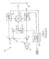
- Figure 1 is a schematic block diagram showing a prior art imaging
apparatus design using reflective spatial light modulators;
- Figure 2 is a schematic block diagram showing a prior art imaging
apparatus design using transmissive spatial light modulators;
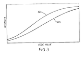
- Figure 3 shows modulation response of a typical electro-optical
device, based on bias voltage level;
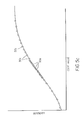
- Figures 4a and 4b show two different mappings of input code
values to discrete intensity values for a spatial light modulator provided with the
same bias voltage level;
- Figure 4c shows an example of an enhanced light intensity
mapping to code values with the example values of Figures 4a and 4b, using the
method of the present invention;
- Figures 5a and 5b show alternate mappings of input code values,
where the mapped intensity values can be clustered or broadly spread;
- Figure 5c shows an alternate example of an enhanced light
intensity mapping to code values with the example values of Figures 5a and 5b,
using the method of the present invention;
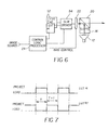
- Figure 6 is a schematic block diagram showing key components
along a single color channel in one embodiment of the present invention;
- Figure 7 is a timing chart showing the timing interrelationship
between loading and using look-up tables in one embodiment of the present
invention;
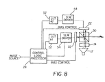
- Figure 8 is a schematic block diagram showing key components
along a single color channel in an alternate embodiment of the present invention;
- Figure 9 is a schematic block diagram showing key components
along a single color channel in an embodiment of the present invention for
immersive systems;
- Figure 10 is a flow chart showing the setup of a single color
channel for the immersive system embodiment shown in Figure 9; and
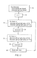
- Figure 11 is a flow chart showing the projection steps for the
immersive system embodiment shown in Figure 9.
-
-
The present invention will be directed in particular to elements
forming part of, or in cooperation more directly with the apparatus in accordance
with the present invention. It is to be understood that elements not specifically
shown or described may take various forms well known to those skilled in the art.
-
Referring now to Figure 1 there is shown, in block diagram form,
an imaging apparatus 10 that uses a number of spatial light modulators 22 that are
of the reflective type. For comparison, Figure 2 shows a block diagram of
imaging apparatus 10 using spatial light modulators 22 of the transmissive type. It
must be noted that the method and apparatus of the present invention apply to
imaging apparatus 10 using spatial light modulators 22 of either reflective or
transmissive type. For simplicity, the description that follows describes imaging
apparatus 10 using a reflective spatial light modulator 22, following the basic
model of Figure 1. However, the implementation of the method and apparatus of
the present invention could be equally applied to imaging apparatus 10 using
transmissive spatial light modulators 22, with only minor changes that would be
familiar to those skilled in the imaging arts.
-
Referring specifically to Figure 1, it is instructive to trace the optics
path, simplified to its more essential components, and the image data path of
imaging apparatus 10. A light source 12 provides illumination that is conditioned
by uniformizing optics 14. The source light beam is then split, using a series of
dichroic beamsplitters 16 and directed by one or more mirrors 18, into separate
color components, typically red, green, and blue (R, G, B). Each separate color
component is modulated to form a modulated beam by a spatial light modulator
22. The separate R, G, and B modulated beams are then recombined, typically
using an X-prism 30 and focused onto a surface 40. When using spatial light
modulators 22 of the reflective type, as shown in Figure 1, a polarization
beamsplitter 20 is disposed to transmit unmodulated light having the appropriate
polarization characteristics to spatial light modulator 22. Modulated light having
the proper polarization is then reflected from polarization beamsplitter 20 to form
the final image on surface 40.
-
A control logic processor 24 accepts input image data from an
image source and provides output modulation data to spatial light modulators 22.
In addition, control logic processor 24 also controls the bias voltage provided to
each spatial light modulator 22. For simplicity, control logic processor 24 is not
shown in Figure 2; however, the same type of logic control is necessary for spatial
light modulators 22 of the transmissive type.
-
It must be emphasized that the architectures of imaging apparatus
10 shown in Figures 1 and 2 are broadly generalized and admit a number of
different embodiments and additions. For example, light source 12 and its
accompanying uniformizing optics 14 can take any of a number of forms.
Illumination could be provided in separate colors, such as using individual LEDs
or LED arrays or by providing filters. Light source 12 could also be provided by
one or more lasers, depending on the type of imaging apparatus 10. Control logic
processor 24 can be embodied in a number of ways, typically, but not limited to,
using a dedicated microprocessor and support circuitry. Lenses, such as
projection lenses, condensors, and the like, are not shown in Figures 1 and 2 for
simplicity. However, a number of different types of lens arrangements would be
required for guiding and conditioning both unmodulated and modulated light,
depending on the type of imaging apparatus 10. For a printer, for example,
focusing lenses would be required to direct light to surface 40, where surface 40
comprises some form of photosensitive medium. For a projector, on the other
hand, projection lenses would be required to project the final image onto surface
40, where surface 40 is a screen, mirror, or other image-projecting surface.
-
For the purpose of describing the present invention, imaging
apparatus 10, as shown in overview in Figures 1 and 2, can be broadly understood
to be an apparatus that forms an image using one or more spatial light modulators
22. It is instructive to emphasize that the method and apparatus of the present
invention can be broadly applied to such a wide range of imaging apparatus 10
devices.
Spatial Light Modulator 22 Response Characteristics
-
Referring to Figure 3, there is represented a typical response
characteristic of spatial light modulator 22 in providing a level of output light
intensity based on an input code value. As is well known in the imaging arts, the
response characteristic of spatial light modulator 22 can be changed by changing
its applied bias voltage level. A response curve 42a shows the response
characteristic of spatial light modulator 22 at a first bias voltage level. For
comparison, a response curve 42b shows the response characteristic of the same
spatial light modulator 22 at a different bias voltage level. By setting the
maximum and minimum intensity levels, the voltage bias determines the overall
contrast ratio for spatial light modulator 22.
-
Given its characteristic curve as represented in Figure 3, spatial
light modulator 22 exhibits a specific response, in terms of relative intensity,
based on its input code value. Referring to Figure 4a, there are shown discrete
mapped intensity levels 50a obtained for a set of code values. For simplicity, only
a few representative mapped intensity levels 50a are shown. Depending on the
type of spatial light modulator 22 device, the set of mapped intensity levels 50a
thus obtained can be provided by applying different levels of input addressing
voltage or by using different pulse-width modulation intervals, or by a
combination of these methods. It is instructive to note, as subsequent examples
show, that intensity values need not be evenly spaced along the characteristic
response curve of spatial light modulator 22, but can have any suitable distribution
over a range.
-
Given the same bias voltage, thus the same characteristic response
curve, it may be possible to obtain a different set of discrete mapped intensity
levels 50b for the same spatial light modulator 22, as is shown in Figure 4b. This
is the case, for example, if spatial light modulator 22 has an increased bit depth at
its output, but can accept only a lesser number of input code values at its input. A
separate mapping, by means of a look-up table (LUT) could provide different
intensity output levels by correlating the same input image data value to two or
more input code values that are provided to the spatial light modulator 22. Thus,
for example, a first LUT would map a specific input image data value to a first
input code value; a second LUT would map the same input image data value to a
second input code value. Where imaging apparatus 10 is a printer, for example,
this arrangement allows exposure of one set of pixels through the first LUT and
exposure of alternate pixels through the second LUT. Where imaging apparatus
10 is a projector, on the other hand, the capability for obtaining different output
intensity levels for the same pixel may be used to obtain an expanded number of
intensity values within a range.
Obtaining Increased Number of Intensity Levels
-
In any imaging apparatus 10 implementation, spatial light
modulator 22 is limited to a discrete number of possible output intensity levels,
based on characteristics of the device. The method of the present invention
applies biasing, mapping, and timing techniques in order to increase the effective
number of intensity levels that is obtainable when using one or more spatial light
modulators 22.
-
Using a combination of LUTs and a multiplexed timing
arrangement, it can readily be seen that it would be possible to combine different
response curves 42a/b as represented in Figures 4a and 4b in order to achieve a
combined response as represented in Figure 4c. Here, the set of mapped intensity
levels 50 that can be provided by a spatial light modulator 22 is a combination of
mapped intensity levels 50a and 50b as shown.
-
Referring back to Figure 3, it can be readily appreciated that it
would also be possible to achieve different mapped intensity levels 50 from one
spatial light modulator 22 by applying, in alternating fashion, one of two different
bias voltages to the spatial light modulator 22. This adjustment, in combination
with providing different mappings of input image data to input code values using
different LUTs, could be used to effectively increase the available number of
output intensity levels that could be reached using a single spatial light modulator
22.
-
For some imaging conditions, particularly in printing applications,
it may be useful to obtain enhanced intensity response over a well-defined range.
For example, for reproduction of flesh tones or neutrals, it can be advantageous to
provide finer gradations of intensity over a mid-tone range. Referring to Figure
5a, there is shown, for a spatial light modulator 22, a mapping with a broad
distribution of mapped intensity levels 50c, such as would be most useful for
obtaining saturated colors. By comparison, referring to Figure 5b, there is shown
a mapping having a narrower distribution of mapped intensity levels 50d, such as
would be most useful for obtaining flesh tones or mid-tones. Referring to Figure
5c, there is represented what a combination of broadly (Figure 5a) and narrowly
(Figure 5b) distributed mapped intensity levels 50c and 50d can mean in an
imaging application. With two spatial light modulators 22 calibrated for such an
arrangement of output intensities, for example, one spatial light modulator 22 can
be used for imaging saturated colors; the other spatial light modulator 22 can be
used for imaging neutral tones. As a result, more control over color is provided
for imaging with this method. Alternately, given appropriate setup of voltage bias
and LUT mapping, a single spatial light modulator 22 can be adapted to provide
the benefits of enhanced intensity range, as suggested graphically in Figure 5c.
Implementation Options
-
It can readily be appreciated that there can be a number of alternate
implementation schemes used to manipulate bias voltage settings, input image
data to input code value mappings, and timing in order to obtain an increased
number of intensity values for imaging apparatus 10.
-
Referring to Figure 6, there is shown, in schematic form, the
implementation of a single color channel in the simplest case of the preferred
embodiment. Two LUTs 52 are provided to allow different mappings of input
image data to input code values. A spatial light modulator driver 54 provides the
support circuitry for modulating spatial light modulator 22. Control logic
processor 24 controls the switching of each group of input image data to either the
first or second LUT 52 and controls the operation of spatial light modulator driver
54 for each group of image data. In a preferred embodiment, the group of image
data handled at one time represents a complete image frame. Other groupings are
possible, typically in units of frames or in some fraction of a frame. Control logic
processor 24 also provides bias control for adjusting spatial light modulator 22
voltage bias. This allows the option of setting a bias voltage that is best suited for
use with first or second LUT 52. The bias voltage may not need to be changed
when switching between LUTs 52.
-
Referring to Figure 7, there is shown a timing relationship for
activating and using the LUTs 52 separately and for optionally changing voltage
bias, using the example implementation of Figure 6. As shown in Figure 7, a
simple alternating scheme would allow setup of conditions for achieving an
increase in the number of intensity levels. Thus, for example, mapped intensity
levels 50a of Figure 4a would be stored in first LUT 52 of Figure 6. Similarly,
mapped intensity levels 50b of Figure 4b would be stored in second LUT 52 of
Figure 6. During time interval T of Figure 7, the group of input image data
mapped through first LUT 52 of Figure 6 would be actively modulating spatial
light modulator 22, with voltage bias set at a first level. During this same time
interval T, control logic processor 24 would be loading a group of input image
data in readiness for use with second LUT #2. At next interval T+1, input image
data mapped through second LUT 52 would be modulated, with voltage bias set at
a second level. It is instructive to note that the same group of input image data
may be loaded to LUT #1 and LUT #2 for modulation under different mapping
and bias conditions in successive intervals.
-
As is readily understood to those familiar in the imaging arts, the
averaging or integration activity of the human eye must be considered when using
a timing arrangement such as is described above with reference to Figures 6 and 7.
To avoid flicker in a projection apparatus, time interval T must be short enough to
allow the appearance of continuous illumination. For this purpose, a time interval
of 16 msec or shorter is sufficient.
-
Referring to Figure 8, there is shown, in schematic form, the
implementation of a more complex embodiment, in which a single color channel
utilizes two spatial light modulators 22. The arrangement of Figure 8, while more
costly to implement, provides the advantage of added brightness, since it would
not be necessary to alternate the use of first and second LUT 52 data for
modulation. Instead, both spatial light modulators 22 would be active at the same
time, each spatial light modulator 22 modulating the appropriate set of image
pixels. The voltage bias levels of the two spatial light modulators 22 would be set
separately. Control logic processor 24 would be programmed with logic
instructions for parsing the input image data in order to determine how to divide
the data for each image frame into two sets, one set for each spatial light
modulator 22.
-
It can readily be appreciated that the arrangement of components
for imaging apparatus 10 in Figures 6 and 8 could be extended to each color
channel. While Figures 6 and 8 show components for using reflective spatial light
modulators 22, a similar arrangement would serve for using transmissive spatial
light modulators 22.
Calibration
-
Calibration of
imaging apparatus 10 allows use of multiple LUTs
and multiple voltage bias settings during imaging operation. The calibration steps
for
LUT #1 and #2 52 setup to provide expanded bit depth are similar to those
typically used in calibration of conventional imaging devices. In outline, this
would require the following basic steps:
- (1) apply a first bias voltage to spatial light modulator 22;
- (2) for each of n input code values, illuminate and
modulate spatial light modulator 22 to obtain a
corresponding first light intensity;
- (3) correlate the corresponding first light intensity to each
of the n input code values to generate a first LUT 52;
- (4) apply a second bias voltage to spatial light modulator
22;
- (5) for each of n input code values, illuminate and
modulate spatial light modulator 22 to obtain a
corresponding second light intensity;
- (6) correlate the corresponding second light intensity to
each of the n input code values to generate a second LUT
52.
A number of variations are possible for LUT 52 generation, depending on the
design of imaging apparatus 10 and on its intended environment. For example, it
may not be necessary to change the bias voltage for spatial light modulator 22 in
step (4) above, depending on how the present invention is embodied.-
Stereoscopic Projection System Implementation
-
The method and apparatus of the present invention are also well-suited
to implementation with stereoscopic projection systems, in which separate
images are provided for left and right eyes of an observer.
-
Figure 9 is a schematic block diagram showing key components
along a single color channel in an embodiment of the present invention for a
stereoscopic imaging apparatus 100. Here, a separate left image 56l and a
separate right image 56r are presented by a corresponding left optical system 46l
and right optical system 46r, respectively, to an observer 58. As is shown in
Figure 9, the image processing and optical components for left and right optical
systems 46l and 46r are basically identical; only image data changes are necessary
for providing the proper scene content for left and right images 56l and 56r. The
optical paths, control functions, and timing are parallel to those described with
reference to Figures 6, 7, and 8 above.
-
Of special concern for design of stereoscopic imaging apparatus
100 using a multiplexed timing scheme such as shown in Figure 7 is maintaining a
proper balance between brightness for left and right images 56l and 56r. With this
type of balance setup in mind, Figure 10 is a flow chart illustrating the typical
flow of stages in setup of a single color channel for stereoscopic imaging
apparatus 100 as in the embodiment shown in Figure 9. In a characterization step
60, a response curve, similar to that shown in Figure 3, is obtained for spatial light
modulator 22 in left optical system 46l. A voltage bias is determined to set the
necessary contrast ratio for spatial light modulator 22. LUT mapping steps 62
then follow for first and second LUTs 52a and 52b in left optical system 46l, in
order to obtain code value to intensity mappings similar to those of Figures 4a and
4b and corresponding input image data to code value mappings needed to obtain
the desired mapped intensity levels 50. In a characterization and balance
adjustment step 64, a response curve is similarly obtained for spatial light
modulator 22 in right optical system 46r. A voltage bias is determined to set the
contrast ratio for spatial light modulator 22 in right optical system 46r. In
addition, adjustments can be made to balance brightness settings and contrast ratio
for suitable left- and right-eye response.
-
Additional LUT mapping steps 62 then follow for third and fourth
LUTs 52c and 52d in right optical system 46r, in order to obtain code value to
intensity mappings similar to those of Figures 4a and 4b and corresponding input
image data to code value mappings needed to obtain the desired mapped intensity
levels 50. This provides initial setup necessary for implementation of the present
invention in stereoscopic imaging apparatus 100.
-
Referring to Figure 11, there is shown the overall sequencing of
steps for projection of the stereoscopic image comprising left and right images 56l
and 56r in stereoscopic imaging apparatus 100. In an initial illumination step,
light sources 12 for both left and right optical systems 46l and 46r are activated.
An initialization step 72 begins the sequencing, represented in Figure 11 as
variable n for a looping operation that follows. In a frame modulation step 74, for
the duration of an image frame, left optical system 46l modulates light using first
LUT 52a. Simultaneously, right optical system 46r modulates light using third
LUT 52c. An increment step 76 follows to move to the next frame. In a
subsequent frame modulation step 78, for the duration of an image frame, left
optical system 46l modulates light using second LUT 52b. Simultaneously, right
optical system 46r modulates light using fourth LUT 52d. Again, increment step
76 follows to move to the next frame. A test and repeat step 80 continues looping
action through frame modulation steps 74 and 78 and the intervening control steps
76 until imaging operation is complete.
Alternate Embodiments
-
The present invention permits a number of alternate embodiments.
For example, where two LUTs 52 are shown per channel, it would be possible to
set up any number of additional LUTs 52 to suit different types of media, different
types of images, audience preferences, and other variables. The image data itself
could include data used to specify the setup of LUTs 52 and to set voltage bias
levels for spatial light modulator 22 in order to achieve special imaging effects.
-
Where imaging system 10 is a printer, additional components could
be employed to allow control logic processor 24 to sense and respond to the
specific type of photosensitive media used as surface 40. Information encoded on
the media or coupled to the media or to media packaging in some way could be
used to specify LUT data itself, to give a recommended bias voltage setting, or to
specify a mode for which an individual device should be set up for imaging.
Similarly, image data for projection could include encoded information on LUT
data or use, voltage bias settings, or preset mode for operation of imaging
apparatus 10.
-
The invention has been described in detail with particular reference
to certain preferred embodiments thereof, but it will be understood that variations
and modifications can be effected within the scope of the invention as described
above, and as noted in the appended claims, by a person of ordinary skill in the art
without departing from the scope of the invention.
-
Thus, what is provided is an apparatus and method for providing an
expanded range of variable light intensity values in an imaging system that uses a
spatial light modulator.