EP1310968A2 - Switch apparatus - Google Patents
Switch apparatus Download PDFInfo
- Publication number
- EP1310968A2 EP1310968A2 EP02024956A EP02024956A EP1310968A2 EP 1310968 A2 EP1310968 A2 EP 1310968A2 EP 02024956 A EP02024956 A EP 02024956A EP 02024956 A EP02024956 A EP 02024956A EP 1310968 A2 EP1310968 A2 EP 1310968A2
- Authority
- EP
- European Patent Office
- Prior art keywords
- pusher
- switch
- operating element
- pushers
- guided
- Prior art date
- Legal status (The legal status is an assumption and is not a legal conclusion. Google has not performed a legal analysis and makes no representation as to the accuracy of the status listed.)
- Granted
Links
- 238000009434 installation Methods 0.000 description 2
- 239000000470 constituent Substances 0.000 description 1
- 230000003247 decreasing effect Effects 0.000 description 1
Images


Classifications
-
- H—ELECTRICITY
- H01—ELECTRIC ELEMENTS
- H01H—ELECTRIC SWITCHES; RELAYS; SELECTORS; EMERGENCY PROTECTIVE DEVICES
- H01H23/00—Tumbler or rocker switches, i.e. switches characterised by being operated by rocking an operating member in the form of a rocker button
- H01H23/02—Details
- H01H23/12—Movable parts; Contacts mounted thereon
- H01H23/16—Driving mechanisms
- H01H23/164—Driving mechanisms with rectilinearly movable member carrying the contacts
Definitions
- an operating element 2 includes an intermediate portion 2a in a lateral direction, as viewed in this figure, which is pivotally supported by a case 1a through a shaft 3 in such a manner as to be able to upwardly and downwardly turn.
- a projection 4 is provided at a portion, which is placed at right side away from the pivotally supported portion (that is, the intermediate portion 2a) of this operating element 2, as viewed in this figure, in such a way as to downwardly project therefrom.
- a linear-rod-like pusher 5 is disposed under the projection 4.
- a pusher guide 7 having a guide hole 6 for guiding this pusher 5 in such a way as to be able to upwardly and downwardly move in a linear direction is formed integrally with the case 1 and thus provided and fixed therein.
- a switch body 8 having an actuator 8a is provided under the pusher 5 by being mounted on a circuit board 9.
- This circuit board 9 is fixed to the case 1.
- the pusher guide 7 is operative to guide the pusher 5 so that the pusher 5 vertical moves in the linear direction in response to an upward or downward turn (that is, a circular arc motion around the shaft 3) of a portion in which the projection 4 of the operating element 2 is present.
- the pusher guide 7 serves to enable the apparatus to properly perform an operation of forcedly pushing the switch body 8, that is, to obtain a reliable conductive state by downwardly and forcedly pushing the switch body 8 in a straight direction. Therefore, the length L1 of the pusher guide 7 should be somewhat large.
- the pusher guide 7 having the length L1 is disposed between the switch body 8 and the projection 4 for forcedly pressing the pusher 5 of the operating element 2. Therefore, the switch body 8, the pusher guide 7, and the operating element 2 are sequentially stacked. Consequently, the conventional apparatus has drawbacks in that the thickness t1 of the entire switch apparatus is large, and that thus, the required installation space of the switch apparatus is large.
- a switch apparatus which comprises an operating element pivotally supported in such a way as to be able to forcedly push and turn in a direction opposite to a direction in which the operating element pushes, a pusher to be pushed by a part of the operating element, which part is disposed at a place located away from a pivotally supported portion thereof, a pusher guide for forcedly pushing and guiding the pusher in such a manner as to be able to move the pusher in a linear direction opposite to a direction in which the pusher is forcedly pushed, and a switch body that undergoes a forced pushing operation to be performed by the pusher.
- a guided portion located away from between the switch body and the part of the operating element, which part forcedly pushes the pusher is formed in the pusher.
- the pusher guide is provided at a place located away from between the switch body and the part of the operating element, which part forcedly pushes the pusher. Furthermore, the pusher guide guides the guided portion in such a way as to be able to move the pusher in the linear direction.
- the invention is characterized by having the following arrangement.
- FIGS. 1 to 3 An embodiment, which is an example of the application of the invention to a volume control switch device for use in an audio apparatus of a vehicle, especially, an automobile, will be described with reference to FIGS. 1 to 3.
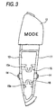
- FIG. 3 there is shown a case 11 that is in a state in which only one of operating elements 12 at one side is mounted on the case 11.
- This case 11 is almost in a boat form.
- the case 11 includes an accommodating portion 13 provided at the side (that is, a lower side, as viewed in FIG. 3) opposite to the side of the operating element 12.
- Pusher guides 15 and 16 are respectively disposed at an upper side part and a lower side part of the accommodating portion 13, as viewed in this figure, and similarly formed in such a way as to be integral therewith.
- These pusher guides 15 and 16 form T-shaped grooves 15a and 16a, respectively, and are respectively placed at upper and lower positions in such a manner as to be symmetrical with respect to the center of the portion 13.
- the groove 15a of the upper pusher guide 15 is upwardly opened, while the groove 16a of the lower pusher guide 16 is downwardly opened.
- a circuit board 19, on which switch bodies 17 and 18 are mounted is accommodated and fixed in the accommodating portion 13.
- the switch bodies 17 and 18 are constituted by tact switches, and respectively have actuators 17a and 18a, each of which protrudes upwardly. Further, these switch bodies 17, 18 are placed closer to the side opposite to the projection 14 (that is, to the side of a counter-projection 14) than the pusher guides 15 and 16.
- Pushers 20 and 21 are placed on the switch bodies 17 and 18, respectively. As illustrated in FIG. 2, each of these pushers 20 and 21 is formed so that a corresponding one of guided portions 20a and 21a is integral with corresponding ones of arms 20b and 21b and main body portions 20c and 21c.
- Each of the guided portions 20a and 21a has a planar T-shaped configuration, similarly as the grooves 15a and 16a of the pusher guides 15 and 16, and upwardly and downwardly extends in such a way as to have a length L11.
- the arms 20b and 21b are extended from the guided portions 20a and 21a, respectively.
- Each of the main body portions 20c and 21c is formed under an end portion of a corresponding one of the arms 20b and 21b.
- each of the main body portions 20c and 21c is shaped like a short-length circular cylinder, and has a length L12 that is shorter than the length L11 of the guided portions 20a and 21a.
- each of the guided portions 20a and 21a is inserted into a corresponding one of the grooves 15a and 16a of the pusher guides 15 and 16 from above.
- the pushers 20 and 21 are enabled to upwardly and downwardly move in a linear direction by guiding the guided portions 20a and 21a.
- the pusher guide 15 and 16 have a length that is nearly equal to the length L11 of the guided portions 20a and 21a.
- the arms 20b and 21b are respectively projected from left-side and right-side opened apertures.
- the main body portions 20c and 21c are put on the actuators 17a and 18a of the switch bodies 17 and 18, respectively.
- the operating element 22 is shaped like a cap that is much larger than the accommodating portion 13.
- a shaft journal part of the operating element 22 is formed at a lower part of the central portion of the operating element 22 in such a way as to be integral therewith.
- the top face of the operating element 22 has a warp that is curved from the central part thereof upward to lateral sides thereof, as viewed in FIG. 1.
- the operating element 22 includes projections 24 and 25 formed at places, which are located laterally away from the central part thereof, on the bottom face of the operating element 22 in such a manner as to protrude therefrom, as viewed in FIG. 1.
- the journal part of the operating element 22 is fitted onto each of the projections 14 of the case 11. Consequently, the operating element 22 is attached and supported thereon in such a way as to be able to upwardly and downwardly turn around each of the projections 14.
- the direction of the upward or downward turn of the operating element 22 is a forced pushing direction in which the operating element 22 is forcedly pushed, or a direction opposite to the forced pushing direction.
- This attachment of the operating element 22 results in that the bottom ends of the projections 24 and 25 are put on the main body portions 20c and 21c of the pushers 20 and 21.
- the operating element 22 is adapted so that the entirety thereof covers the whole accommodating portion 13.
- the projections 24 and 25 are placed at parts located laterally away from the central portion of the operating element 22 pivotally supported by the projection 14 of the case 11, that is, the pivotally supported part of the operating element 22. Therefore, the pushers 20 and 21 are forcedly pushed by the parts located away from the pivotally supported portion of the operating element 22.
- the pushed pushers 20 and 21 are respectively guided by the pusher guides 15 and 16, which act upon the guided portions 20a and 20b, in such away as to downwardly move in a linear direction.
- the movement of the pusher 20 results in that the actuator 17a of the switch body 17 is downwardly pushed.
- the switch body 17 undergoes a forced pushing operation, so that the switch apparatus is put into a conducting state.
- the magnitude of sounds radiated from the audio apparatus of the automobile is increased.
- the movement of the pusher 21 results in that the actuator 18a of the switch body 18 is downwardly and forcedly pushed.
- the switch body 18 undergoes a forcedly pushing operation, so that similarly, the switch apparatus is put into a conducting state.
- the magnitude of sounds radiated from the audio apparatus of the automobile is decreased.
- the aforementioned length L11 of the pusher guides 15 and 16 is a length required to cause the pushers 20 and 21 to properly perform operations of forcedly pushing the switch bodies 17 and 18.
- each of the pusher guides 15 and 16 is disposed away from a portion between a corresponding one of the switch bodies 17, 18 and a corresponding one of the parts (the projections 24 and 25) which push the pushers 20 and 21 of the operating element 22, toward the projection 14 of the case 11, which is a support shaft for the operating element 22.
- Each of the guided portions 20a and 21a of the pushers 20a and 21a of the pushers 20 and 21 is disposed away from a portion between a corresponding one of the switch bodies 17, 18 and a corresponding one of the parts (the projections 24 and 25) which forcedly push the pushers 20 and 21 of the operating element 22, toward the projection 14 of the case 11.
- the pushers 20 and 21 are upwardly pushed back by restoring forces of the switch bodies 17 and 18. Moreover, the operating element 22 is upwardly pushed back through the projections 24 and 25, which respectively return the actuators 17a and 18a. Furthermore, as the pushers 20 and 21 are pushed back, the switch bodies 17 and 18 return to an interrupting state.
- each of the pushers 20 and 21 is guided by a corresponding one of the pusher guides 15 and 16 at a place away from between a corresponding one of the switch bodies 17 and 18 and a corresponding one of the parts which push the pushers 20 and 21 of the operating element 22. Therefore, the necessary length L11 of each of the pusher guides 15 and 16 for properly performing operations of forcedly pushing a corresponding one of the switch bodies 17 and 18 is assured at a place away from a portion between a corresponding one of the switch bodies 17 and 18 and a corresponding one of the parts of the operating element 22, which are used for forcedly pushing the pushers 20 and 21.
- the scope of application of the invention is not limited to a volume control switch device for use in an audio apparatus of a vehicle, especially, an automobile.
- the invention may be widely applied to general switch devices.
- each of the guided portions 20a and 21a of the pushers 20 and 21 and the pusher guides 15 and 16 may be placed at a position located away from therebetween to a side opposite to the projection 14.
- the pusher guides 15 and 16 may be formed in such a manner as to be separated from the case 11 and fixed. by being incorporated into the case 11, instead of being formed in such a way as to be integral with the case 11.
- the switch bodies 17 and 18 are not limited to tact switches. Furthermore, any other switches may be employed as long as an operation of forcedly pushing thereof is per formed by the pushers 20 and 21.
- the invention is not limited to the embodiments described above and illustrated in the accompanying drawings. Especially, the invention can be practiced by suitably changing the practical shapes of constituent elements of the invention without departing from the gist thereof.
- an operation of forcedly pushing the switch body can be properly performed. Moreover, the thickness of the entire switch apparatus can be reduced.
Abstract
Description
- The present invention relates to a switch apparatus having a pusher provided between an operating element and a switch body.
- Hitherto, a conventional apparatus illustrated in FIG. 4 has been provided as a switch apparatus having a pusher provided between an operating element and a switch body. In this conventional apparatus, an
operating element 2 includes anintermediate portion 2a in a lateral direction, as viewed in this figure, which is pivotally supported by a case 1a through ashaft 3 in such a manner as to be able to upwardly and downwardly turn. Aprojection 4 is provided at a portion, which is placed at right side away from the pivotally supported portion (that is, theintermediate portion 2a) of thisoperating element 2, as viewed in this figure, in such a way as to downwardly project therefrom. - A linear-rod-
like pusher 5 is disposed under theprojection 4. Apusher guide 7 having aguide hole 6 for guiding thispusher 5 in such a way as to be able to upwardly and downwardly move in a linear direction is formed integrally with the case 1 and thus provided and fixed therein. - A switch body 8 having an
actuator 8a is provided under thepusher 5 by being mounted on a circuit board 9. This circuit board 9 is fixed to the case 1. - In the conventional apparatus of this configuration, when the right-side portion of the
operating element 2 is downwardly pushed down into a space, theprojection 4 downwardly pushes thepusher 5. Then, thepusher 5 downwardly pushes theactuator 8a of the switch body 8. Thus, an operation of forcedly pushing the switch body 8 is performed, so that the switch body 8 is put into a conducting state.
When the forced pushing of theoperating element 2 is canceled from the pushing state, thepusher 5 is upwardly pushed back by a restoring force of the switch body 8 which returns theactuator 8a, and the right-side portion of theoperating element 2 is upwardly pushed back through theprojection 4. As thepusher 5 is pushed back, the switch body 8 returns to an interrupting state. - In the aforementioned conventional apparatus, the
pusher guide 7 is operative to guide thepusher 5 so that thepusher 5 vertical moves in the linear direction in response to an upward or downward turn (that is, a circular arc motion around the shaft 3) of a portion in which theprojection 4 of theoperating element 2 is present. Thus, thepusher guide 7 serves to enable the apparatus to properly perform an operation of forcedly pushing the switch body 8, that is, to obtain a reliable conductive state by downwardly and forcedly pushing the switch body 8 in a straight direction. Therefore, the length L1 of thepusher guide 7 should be somewhat large. - Thus, in the case of the aforementioned conventional apparatus, the
pusher guide 7 having the length L1 is disposed between the switch body 8 and theprojection 4 for forcedly pressing thepusher 5 of theoperating element 2. Therefore, the switch body 8, thepusher guide 7, and theoperating element 2 are sequentially stacked. Consequently, the conventional apparatus has drawbacks in that the thickness t1 of the entire switch apparatus is large, and that thus, the required installation space of the switch apparatus is large. - The invention is accomplished in view of the aforementioned circumstances. Accordingly, an object of the invention is to provide a switch apparatus enabled to properly perform an operation of forcedly pushing a switch body and to reduce the thickness of the entirety thereof.
- To achieve the foregoing object, according to the invention, there is provided a switch apparatus, which comprises an operating element pivotally supported in such a way as to be able to forcedly push and turn in a direction opposite to a direction in which the operating element pushes, a pusher to be pushed by a part of the operating element, which part is disposed at a place located away from a pivotally supported portion thereof, a pusher guide for forcedly pushing and guiding the pusher in such a manner as to be able to move the pusher in a linear direction opposite to a direction in which the pusher is forcedly pushed, and a switch body that undergoes a forced pushing operation to be performed by the pusher. In this apparatus, a guided portion located away from between the switch body and the part of the operating element, which part forcedly pushes the pusher, is formed in the pusher. Further, the pusher guide is provided at a place located away from between the switch body and the part of the operating element, which part forcedly pushes the pusher. Furthermore, the pusher guide guides the guided portion in such a way as to be able to move the pusher in the linear direction.
- In order to solve the aforesaid object, the invention is characterized by having the following arrangement.
- (1) A switch apparatus comprising:
- an operating element pivotally supported through a pivotally supported portion thereof;
- a pusher to be pushed by a pushing part of the operating element, the pushing part being disposed at a place shifted from the pivotally supported portion;
- a switch body to be pushed by the pusher;
- a guided portion away from a portion between the switch body and the pushing part, formed in the pusher; and
- a pusher guide for guiding the guided portion in a linear direction, which is arranged at a place away from the portion between the switch body and the pushing part.
- (2) The switch apparatus according to (1), wherein the pusher includes the guided portion guided by the pusher guide and a main body portion which is pushed by the operating element and pushes the switch body.
- (3) The switch apparatus according to (2), wherein the main body portion is shorter than the guided portion in the linear direction.
- (4) The switch apparatus according to (3), wherein the main body portion is shorter than the pusher guide in the linear direction.
- (5) The switch apparatus according to (2), wherein the pusher includes an arm which is extended in a direction substantially perpendicular to the linear direction and connects the main body portion to the guided portion.
-
-
- FIG. 1 is a broken side view illustrating an embodiment of the invention.
- FIG. 2 is an exploded perspective view illustrating the embodiment.
- FIG. 3 is a plan view illustrating a primary part of a case.
- FIG. 4 is a view illustrating a conventional switch apparatus, which partly corresponds to FIG. 1.
-
- Hereinafter, an embodiment, which is an example of the application of the invention to a volume control switch device for use in an audio apparatus of a vehicle, especially, an automobile, will be described with reference to FIGS. 1 to 3.
- Referring to FIG. 3, there is shown a
case 11 that is in a state in which only one ofoperating elements 12 at one side is mounted on thecase 11. Thiscase 11 is almost in a boat form. Thecase 11 includes anaccommodating portion 13 provided at the side (that is, a lower side, as viewed in FIG. 3) opposite to the side of theoperating element 12. - In an
accommodating portion 13,projections 14 of short length having cylinder shape are formed on the front-side edge portions of both the left-side and right-side walls of a central portion in such a way as to be integral therewith and as to slightly outwardly project therefrom, as viewed in this figure. Pusherguides accommodating portion 13, as viewed in this figure, and similarly formed in such a way as to be integral therewith. These pusher guides 15 and 16 form T-shaped grooves portion 13. Thegroove 15a of theupper pusher guide 15 is upwardly opened, while thegroove 16a of thelower pusher guide 16 is downwardly opened. - On the other hand, as illustrated in FIG. 1, a
circuit board 19, on whichswitch bodies accommodating portion 13. In this case, theswitch bodies actuators switch bodies pusher guides -
Pushers switch bodies pushers portions arms main body portions portions grooves pusher guides arms portions main body portions arms main body portions portions - As shown in FIG. 1, each of the guided
portions grooves pusher guides pushers portions pusher guide portions arms main body portions actuators switch bodies - On the other hand, the operating
element 22 is shaped like a cap that is much larger than theaccommodating portion 13. A shaft journal part of the operatingelement 22 is formed at a lower part of the central portion of the operatingelement 22 in such a way as to be integral therewith. The top face of the operatingelement 22 has a warp that is curved from the central part thereof upward to lateral sides thereof, as viewed in FIG. 1. Moreover, the operatingelement 22 includesprojections element 22 in such a manner as to protrude therefrom, as viewed in FIG. 1. - The journal part of the operating
element 22 is fitted onto each of theprojections 14 of thecase 11. Consequently, the operatingelement 22 is attached and supported thereon in such a way as to be able to upwardly and downwardly turn around each of theprojections 14. In this case, the direction of the upward or downward turn of the operatingelement 22 is a forced pushing direction in which theoperating element 22 is forcedly pushed, or a direction opposite to the forced pushing direction. This attachment of the operatingelement 22 results in that the bottom ends of theprojections main body portions pushers element 22 is adapted so that the entirety thereof covers the wholeaccommodating portion 13. - Incidentally, as shown in FIG. 2,
necessary indications element 22. - With the aforementioned configuration, when the left-side part of the operating
element 22 is downwardly pushed into a space, as viewed in FIG. 1, the operatingelement 22 turns anticlockwise, so that themain body portion 20c of thepusher 20 is pushed down by theprojection 24 that performs a circular arc motion. When the right-side part of the operatingelement 22 is downwardly pushed into a space, as viewed in FIG. 1, the operatingelement 22 turns clockwise, so that themain body portion 21c of thepusher 21 is pushed down by theprojection 25 that performs a circular arc motion. - At that time, the
projections element 22 pivotally supported by theprojection 14 of thecase 11, that is, the pivotally supported part of the operatingelement 22. Therefore, thepushers element 22. The pushedpushers portions - Then, the movement of the
pusher 20 results in that theactuator 17a of theswitch body 17 is downwardly pushed. Thus, theswitch body 17 undergoes a forced pushing operation, so that the switch apparatus is put into a conducting state. In this case, the magnitude of sounds radiated from the audio apparatus of the automobile is increased. Furthermore, the movement of thepusher 21 results in that theactuator 18a of theswitch body 18 is downwardly and forcedly pushed. Thus, theswitch body 18 undergoes a forcedly pushing operation, so that similarly, the switch apparatus is put into a conducting state. In this case, the magnitude of sounds radiated from the audio apparatus of the automobile is decreased. The aforementioned length L11 of the pusher guides 15 and 16 is a length required to cause thepushers switch bodies - At that time, each of the pusher guides 15 and 16 is disposed away from a portion between a corresponding one of the
switch bodies projections 24 and 25) which push thepushers element 22, toward theprojection 14 of thecase 11, which is a support shaft for the operatingelement 22. Each of the guidedportions pushers pushers switch bodies projections 24 and 25) which forcedly push thepushers element 22, toward theprojection 14 of thecase 11. - Incidentally, when the forced pushing of the operating
element 22 is canceled during each of the aforementioned states, thepushers switch bodies element 22 is upwardly pushed back through theprojections actuators pushers switch bodies - Thus, according to the apparatus of this configuration, each of the
pushers switch bodies pushers element 22. Therefore, the necessary length L11 of each of the pusher guides 15 and 16 for properly performing operations of forcedly pushing a corresponding one of theswitch bodies switch bodies element 22, which are used for forcedly pushing thepushers switch bodies switch bodies main body portions pushers - Thus, in the case of the apparatus of this configuration, operations of forcedly pushing the
switch bodies - Incidentally, the scope of application of the invention is not limited to a volume control switch device for use in an audio apparatus of a vehicle, especially, an automobile. The invention may be widely applied to general switch devices. Further, instead of placing each of the guided
portions pushers switch bodies pushers element 22 to theprojection 14 of thecase 11, each of the guidedportions pushers projection 14. - Additionally, the pusher guides 15 and 16 may be formed in such a manner as to be separated from the
case 11 and fixed. by being incorporated into thecase 11, instead of being formed in such a way as to be integral with thecase 11. Moreover, theswitch bodies pushers - Further, the invention is not limited to the embodiments described above and illustrated in the accompanying drawings. Especially, the invention can be practiced by suitably changing the practical shapes of constituent elements of the invention without departing from the gist thereof.
- As described above, according to the switch apparatus of the invention, an operation of forcedly pushing the switch body can be properly performed. Moreover, the thickness of the entire switch apparatus can be reduced.
Claims (5)
- A switch apparatus comprising:an operating element pivotally supported through a pivotally supported portion thereof;a pusher to be pushed by a pushing part of the operating element, the pushing part being disposed at a place shifted from the pivotally supported portion;a switch body to be pushed by the pusher;a guided portion away from a portion between the switch body and the pushing part, formed in the pusher; anda pusher guide for guiding the guided portion in a linear direction, which is arranged at a place away from the portion between the switch body and the pushing part.
- The switch apparatus according to claim 1, wherein the pusher includes the guided portion guided by the pusher guide and a main body portion which is pushed by the operating element and pushes the switch body.
- The switch apparatus according to claim 2, wherein the main body portion is shorter than the guided portion in the linear direction.
- The switch apparatus according to claim 3, wherein the main body portion is shorter than the pusher guide in the linear direction.
- The switch apparatus according to claim 2, wherein the pusher includes an arm which is extended in a direction substantially perpendicular to the linear direction and connects the main body portion to the guided portion.
Applications Claiming Priority (2)
| Application Number | Priority Date | Filing Date | Title |
|---|---|---|---|
| JP2001341895A JP3971159B2 (en) | 2001-11-07 | 2001-11-07 | Switch device |
| JP2001341895 | 2001-11-07 |
Publications (4)
| Publication Number | Publication Date |
|---|---|
| EP1310968A2 true EP1310968A2 (en) | 2003-05-14 |
| EP1310968A3 EP1310968A3 (en) | 2004-12-15 |
| EP1310968B1 EP1310968B1 (en) | 2007-01-17 |
| EP1310968B2 EP1310968B2 (en) | 2010-09-29 |
Family
ID=19155845
Family Applications (1)
| Application Number | Title | Priority Date | Filing Date |
|---|---|---|---|
| EP02024956A Expired - Fee Related EP1310968B2 (en) | 2001-11-07 | 2002-11-06 | Switch apparatus |
Country Status (4)
| Country | Link |
|---|---|
| US (1) | US6605790B2 (en) |
| EP (1) | EP1310968B2 (en) |
| JP (1) | JP3971159B2 (en) |
| DE (1) | DE60217613T3 (en) |
Families Citing this family (98)
| Publication number | Priority date | Publication date | Assignee | Title |
|---|---|---|---|---|
| US6726686B2 (en) | 1997-11-12 | 2004-04-27 | Sherwood Services Ag | Bipolar electrosurgical instrument for sealing vessels |
| US7435249B2 (en) | 1997-11-12 | 2008-10-14 | Covidien Ag | Electrosurgical instruments which reduces collateral damage to adjacent tissue |
| WO2002080786A1 (en) | 2001-04-06 | 2002-10-17 | Sherwood Services Ag | Electrosurgical instrument which reduces collateral damage to adjacent tissue |
| US6228083B1 (en) | 1997-11-14 | 2001-05-08 | Sherwood Services Ag | Laparoscopic bipolar electrosurgical instrument |
| US7118570B2 (en) | 2001-04-06 | 2006-10-10 | Sherwood Services Ag | Vessel sealing forceps with disposable electrodes |
| US7267677B2 (en) | 1998-10-23 | 2007-09-11 | Sherwood Services Ag | Vessel sealing instrument |
| US7582087B2 (en) | 1998-10-23 | 2009-09-01 | Covidien Ag | Vessel sealing instrument |
| US7364577B2 (en) | 2002-02-11 | 2008-04-29 | Sherwood Services Ag | Vessel sealing system |
| US20030109875A1 (en) | 1999-10-22 | 2003-06-12 | Tetzlaff Philip M. | Open vessel sealing forceps with disposable electrodes |
| US7473253B2 (en) | 2001-04-06 | 2009-01-06 | Covidien Ag | Vessel sealer and divider with non-conductive stop members |
| US7009127B2 (en) * | 2002-09-10 | 2006-03-07 | Siemens Ag | Switch comprising an operating rocker button |
| US7931649B2 (en) | 2002-10-04 | 2011-04-26 | Tyco Healthcare Group Lp | Vessel sealing instrument with electrical cutting mechanism |
| US7276068B2 (en) | 2002-10-04 | 2007-10-02 | Sherwood Services Ag | Vessel sealing instrument with electrical cutting mechanism |
| US7270664B2 (en) | 2002-10-04 | 2007-09-18 | Sherwood Services Ag | Vessel sealing instrument with electrical cutting mechanism |
| US7799026B2 (en) | 2002-11-14 | 2010-09-21 | Covidien Ag | Compressible jaw configuration with bipolar RF output electrodes for soft tissue fusion |
| JP2004235059A (en) * | 2003-01-31 | 2004-08-19 | Orion Denki Kk | Recording medium ejection button switch of composite equipment |
| WO2004082495A1 (en) | 2003-03-13 | 2004-09-30 | Sherwood Services Ag | Bipolar concentric electrode assembly for soft tissue fusion |
| EP1617778A2 (en) | 2003-05-01 | 2006-01-25 | Sherwood Services AG | Electrosurgical instrument which reduces thermal damage to adjacent tissue |
| US7160299B2 (en) | 2003-05-01 | 2007-01-09 | Sherwood Services Ag | Method of fusing biomaterials with radiofrequency energy |
| WO2004103156A2 (en) | 2003-05-15 | 2004-12-02 | Sherwood Services Ag | Tissue sealer with non-conductive variable stop members and method of sealing tissue |
| USD956973S1 (en) | 2003-06-13 | 2022-07-05 | Covidien Ag | Movable handle for endoscopic vessel sealer and divider |
| US7857812B2 (en) | 2003-06-13 | 2010-12-28 | Covidien Ag | Vessel sealer and divider having elongated knife stroke and safety for cutting mechanism |
| US7156846B2 (en) | 2003-06-13 | 2007-01-02 | Sherwood Services Ag | Vessel sealer and divider for use with small trocars and cannulas |
| US7150749B2 (en) | 2003-06-13 | 2006-12-19 | Sherwood Services Ag | Vessel sealer and divider having elongated knife stroke and safety cutting mechanism |
| JP3850818B2 (en) * | 2003-06-30 | 2006-11-29 | 小島プレス工業株式会社 | Switch device |
| US9848938B2 (en) | 2003-11-13 | 2017-12-26 | Covidien Ag | Compressible jaw configuration with bipolar RF output electrodes for soft tissue fusion |
| US7367976B2 (en) | 2003-11-17 | 2008-05-06 | Sherwood Services Ag | Bipolar forceps having monopolar extension |
| US7500975B2 (en) | 2003-11-19 | 2009-03-10 | Covidien Ag | Spring loaded reciprocating tissue cutting mechanism in a forceps-style electrosurgical instrument |
| US7131970B2 (en) | 2003-11-19 | 2006-11-07 | Sherwood Services Ag | Open vessel sealing instrument with cutting mechanism |
| US7811283B2 (en) | 2003-11-19 | 2010-10-12 | Covidien Ag | Open vessel sealing instrument with hourglass cutting mechanism and over-ratchet safety |
| US7442193B2 (en) | 2003-11-20 | 2008-10-28 | Covidien Ag | Electrically conductive/insulative over-shoe for tissue fusion |
| US7780662B2 (en) | 2004-03-02 | 2010-08-24 | Covidien Ag | Vessel sealing system using capacitive RF dielectric heating |
| JP2006032059A (en) * | 2004-07-14 | 2006-02-02 | Tokai Rika Co Ltd | Switch device |
| KR100593167B1 (en) * | 2004-07-20 | 2006-06-26 | 주식회사 현대오토넷 | Back lighting interference prevent button in heater control |
| DE102004036844B4 (en) * | 2004-07-29 | 2007-11-08 | Bj Automotive Gmbh | Rocker |
| US7195631B2 (en) | 2004-09-09 | 2007-03-27 | Sherwood Services Ag | Forceps with spring loaded end effector assembly |
| US7540872B2 (en) | 2004-09-21 | 2009-06-02 | Covidien Ag | Articulating bipolar electrosurgical instrument |
| US7955332B2 (en) | 2004-10-08 | 2011-06-07 | Covidien Ag | Mechanism for dividing tissue in a hemostat-style instrument |
| US7686804B2 (en) | 2005-01-14 | 2010-03-30 | Covidien Ag | Vessel sealer and divider with rotating sealer and cutter |
| US7909823B2 (en) | 2005-01-14 | 2011-03-22 | Covidien Ag | Open vessel sealing instrument |
| US7491202B2 (en) | 2005-03-31 | 2009-02-17 | Covidien Ag | Electrosurgical forceps with slow closure sealing plates and method of sealing tissue |
| JP2006331999A (en) * | 2005-05-30 | 2006-12-07 | Toyoda Gosei Co Ltd | Rocking switch |
| CA2561034C (en) | 2005-09-30 | 2014-12-09 | Sherwood Services Ag | Flexible endoscopic catheter with an end effector for coagulating and transfecting tissue |
| US7879035B2 (en) | 2005-09-30 | 2011-02-01 | Covidien Ag | Insulating boot for electrosurgical forceps |
| US7922953B2 (en) | 2005-09-30 | 2011-04-12 | Covidien Ag | Method for manufacturing an end effector assembly |
| US7789878B2 (en) | 2005-09-30 | 2010-09-07 | Covidien Ag | In-line vessel sealer and divider |
| US7722607B2 (en) | 2005-09-30 | 2010-05-25 | Covidien Ag | In-line vessel sealer and divider |
| EP1769765B1 (en) | 2005-09-30 | 2012-03-21 | Covidien AG | Insulating boot for electrosurgical forceps |
| US8298232B2 (en) | 2006-01-24 | 2012-10-30 | Tyco Healthcare Group Lp | Endoscopic vessel sealer and divider for large tissue structures |
| US8882766B2 (en) | 2006-01-24 | 2014-11-11 | Covidien Ag | Method and system for controlling delivery of energy to divide tissue |
| US8241282B2 (en) | 2006-01-24 | 2012-08-14 | Tyco Healthcare Group Lp | Vessel sealing cutting assemblies |
| US8734443B2 (en) | 2006-01-24 | 2014-05-27 | Covidien Lp | Vessel sealer and divider for large tissue structures |
| US7776037B2 (en) | 2006-07-07 | 2010-08-17 | Covidien Ag | System and method for controlling electrode gap during tissue sealing |
| US8597297B2 (en) | 2006-08-29 | 2013-12-03 | Covidien Ag | Vessel sealing instrument with multiple electrode configurations |
| US8070746B2 (en) | 2006-10-03 | 2011-12-06 | Tyco Healthcare Group Lp | Radiofrequency fusion of cardiac tissue |
| USD649249S1 (en) | 2007-02-15 | 2011-11-22 | Tyco Healthcare Group Lp | End effectors of an elongated dissecting and dividing instrument |
| US8267935B2 (en) | 2007-04-04 | 2012-09-18 | Tyco Healthcare Group Lp | Electrosurgical instrument reducing current densities at an insulator conductor junction |
| US7877852B2 (en) | 2007-09-20 | 2011-02-01 | Tyco Healthcare Group Lp | Method of manufacturing an end effector assembly for sealing tissue |
| US7877853B2 (en) | 2007-09-20 | 2011-02-01 | Tyco Healthcare Group Lp | Method of manufacturing end effector assembly for sealing tissue |
| US8235993B2 (en) | 2007-09-28 | 2012-08-07 | Tyco Healthcare Group Lp | Insulating boot for electrosurgical forceps with exohinged structure |
| AU2008221509B2 (en) | 2007-09-28 | 2013-10-10 | Covidien Lp | Dual durometer insulating boot for electrosurgical forceps |
| US8267936B2 (en) | 2007-09-28 | 2012-09-18 | Tyco Healthcare Group Lp | Insulating mechanically-interfaced adhesive for electrosurgical forceps |
| US8251996B2 (en) | 2007-09-28 | 2012-08-28 | Tyco Healthcare Group Lp | Insulating sheath for electrosurgical forceps |
| US8235992B2 (en) | 2007-09-28 | 2012-08-07 | Tyco Healthcare Group Lp | Insulating boot with mechanical reinforcement for electrosurgical forceps |
| US9023043B2 (en) | 2007-09-28 | 2015-05-05 | Covidien Lp | Insulating mechanically-interfaced boot and jaws for electrosurgical forceps |
| US8236025B2 (en) | 2007-09-28 | 2012-08-07 | Tyco Healthcare Group Lp | Silicone insulated electrosurgical forceps |
| US8221416B2 (en) | 2007-09-28 | 2012-07-17 | Tyco Healthcare Group Lp | Insulating boot for electrosurgical forceps with thermoplastic clevis |
| US8764748B2 (en) | 2008-02-06 | 2014-07-01 | Covidien Lp | End effector assembly for electrosurgical device and method for making the same |
| US8623276B2 (en) | 2008-02-15 | 2014-01-07 | Covidien Lp | Method and system for sterilizing an electrosurgical instrument |
| US8469956B2 (en) | 2008-07-21 | 2013-06-25 | Covidien Lp | Variable resistor jaw |
| US8162973B2 (en) | 2008-08-15 | 2012-04-24 | Tyco Healthcare Group Lp | Method of transferring pressure in an articulating surgical instrument |
| US8257387B2 (en) | 2008-08-15 | 2012-09-04 | Tyco Healthcare Group Lp | Method of transferring pressure in an articulating surgical instrument |
| US9603652B2 (en) | 2008-08-21 | 2017-03-28 | Covidien Lp | Electrosurgical instrument including a sensor |
| US8795274B2 (en) | 2008-08-28 | 2014-08-05 | Covidien Lp | Tissue fusion jaw angle improvement |
| US8317787B2 (en) | 2008-08-28 | 2012-11-27 | Covidien Lp | Tissue fusion jaw angle improvement |
| US8784417B2 (en) | 2008-08-28 | 2014-07-22 | Covidien Lp | Tissue fusion jaw angle improvement |
| US8303582B2 (en) | 2008-09-15 | 2012-11-06 | Tyco Healthcare Group Lp | Electrosurgical instrument having a coated electrode utilizing an atomic layer deposition technique |
| US9375254B2 (en) | 2008-09-25 | 2016-06-28 | Covidien Lp | Seal and separate algorithm |
| US8535312B2 (en) | 2008-09-25 | 2013-09-17 | Covidien Lp | Apparatus, system and method for performing an electrosurgical procedure |
| US8968314B2 (en) | 2008-09-25 | 2015-03-03 | Covidien Lp | Apparatus, system and method for performing an electrosurgical procedure |
| US8142473B2 (en) | 2008-10-03 | 2012-03-27 | Tyco Healthcare Group Lp | Method of transferring rotational motion in an articulating surgical instrument |
| US8469957B2 (en) | 2008-10-07 | 2013-06-25 | Covidien Lp | Apparatus, system, and method for performing an electrosurgical procedure |
| US8016827B2 (en) | 2008-10-09 | 2011-09-13 | Tyco Healthcare Group Lp | Apparatus, system, and method for performing an electrosurgical procedure |
| US8636761B2 (en) | 2008-10-09 | 2014-01-28 | Covidien Lp | Apparatus, system, and method for performing an endoscopic electrosurgical procedure |
| US8486107B2 (en) | 2008-10-20 | 2013-07-16 | Covidien Lp | Method of sealing tissue using radiofrequency energy |
| US8197479B2 (en) | 2008-12-10 | 2012-06-12 | Tyco Healthcare Group Lp | Vessel sealer and divider |
| US8114122B2 (en) | 2009-01-13 | 2012-02-14 | Tyco Healthcare Group Lp | Apparatus, system, and method for performing an electrosurgical procedure |
| US8187273B2 (en) | 2009-05-07 | 2012-05-29 | Tyco Healthcare Group Lp | Apparatus, system, and method for performing an electrosurgical procedure |
| US8246618B2 (en) | 2009-07-08 | 2012-08-21 | Tyco Healthcare Group Lp | Electrosurgical jaws with offset knife |
| US8133254B2 (en) | 2009-09-18 | 2012-03-13 | Tyco Healthcare Group Lp | In vivo attachable and detachable end effector assembly and laparoscopic surgical instrument and methods therefor |
| US8112871B2 (en) | 2009-09-28 | 2012-02-14 | Tyco Healthcare Group Lp | Method for manufacturing electrosurgical seal plates |
| US9113940B2 (en) | 2011-01-14 | 2015-08-25 | Covidien Lp | Trigger lockout and kickback mechanism for surgical instruments |
| USD680220S1 (en) | 2012-01-12 | 2013-04-16 | Coviden IP | Slider handle for laparoscopic device |
| WO2015017992A1 (en) | 2013-08-07 | 2015-02-12 | Covidien Lp | Surgical forceps |
| US10231777B2 (en) | 2014-08-26 | 2019-03-19 | Covidien Lp | Methods of manufacturing jaw members of an end-effector assembly for a surgical instrument |
| WO2017031712A1 (en) | 2015-08-26 | 2017-03-02 | Covidien Lp | Electrosurgical end effector assemblies and electrosurgical forceps configured to reduce thermal spread |
| US10213250B2 (en) | 2015-11-05 | 2019-02-26 | Covidien Lp | Deployment and safety mechanisms for surgical instruments |
| US11166759B2 (en) | 2017-05-16 | 2021-11-09 | Covidien Lp | Surgical forceps |
Citations (7)
| Publication number | Priority date | Publication date | Assignee | Title |
|---|---|---|---|---|
| US4425487A (en) * | 1982-09-16 | 1984-01-10 | General Motors Corporation | Unitized manual actuator assembly for unitized electrical switch |
| DE19517538A1 (en) † | 1994-05-12 | 1995-11-30 | Alps Electric Co Ltd | Four-way action rocker switch |
| DE19544769A1 (en) † | 1995-11-30 | 1997-06-05 | Cherry Mikroschalter Gmbh | Electromechanical rocker actuated bistable switch |
| US5689095A (en) * | 1993-09-20 | 1997-11-18 | Kabushiki Kaisha Tokai Rika Denki Seisakusho | Switching device |
| EP0957498A2 (en) † | 1998-05-11 | 1999-11-17 | Eaton Corporation | Power window switch |
| US6140713A (en) * | 1999-03-02 | 2000-10-31 | Methode Electronics, Inc. | Electrical cammed switch |
| EP1300859A2 (en) † | 2001-10-03 | 2003-04-09 | Kabushiki Kaisha Tokai Rika Denki Seisakusho | Switch operating mechanism |
Family Cites Families (3)
| Publication number | Priority date | Publication date | Assignee | Title |
|---|---|---|---|---|
| US5584380A (en) * | 1993-09-02 | 1996-12-17 | Sumitomo Wiring Systems, Ltd. | Seesaw switch |
| US5691517A (en) * | 1993-11-19 | 1997-11-25 | Sumitomo Wiring Systems, Ltd. | Multidirectional lever switch device |
| US5957273A (en) * | 1997-07-22 | 1999-09-28 | Ut Automotive Dearborn, Inc. | Universal switch |
-
2001
- 2001-11-07 JP JP2001341895A patent/JP3971159B2/en not_active Expired - Fee Related
-
2002
- 2002-10-23 US US10/277,743 patent/US6605790B2/en not_active Expired - Lifetime
- 2002-11-06 DE DE60217613T patent/DE60217613T3/en not_active Expired - Lifetime
- 2002-11-06 EP EP02024956A patent/EP1310968B2/en not_active Expired - Fee Related
Patent Citations (7)
| Publication number | Priority date | Publication date | Assignee | Title |
|---|---|---|---|---|
| US4425487A (en) * | 1982-09-16 | 1984-01-10 | General Motors Corporation | Unitized manual actuator assembly for unitized electrical switch |
| US5689095A (en) * | 1993-09-20 | 1997-11-18 | Kabushiki Kaisha Tokai Rika Denki Seisakusho | Switching device |
| DE19517538A1 (en) † | 1994-05-12 | 1995-11-30 | Alps Electric Co Ltd | Four-way action rocker switch |
| DE19544769A1 (en) † | 1995-11-30 | 1997-06-05 | Cherry Mikroschalter Gmbh | Electromechanical rocker actuated bistable switch |
| EP0957498A2 (en) † | 1998-05-11 | 1999-11-17 | Eaton Corporation | Power window switch |
| US6140713A (en) * | 1999-03-02 | 2000-10-31 | Methode Electronics, Inc. | Electrical cammed switch |
| EP1300859A2 (en) † | 2001-10-03 | 2003-04-09 | Kabushiki Kaisha Tokai Rika Denki Seisakusho | Switch operating mechanism |
Also Published As
| Publication number | Publication date |
|---|---|
| JP3971159B2 (en) | 2007-09-05 |
| US6605790B2 (en) | 2003-08-12 |
| EP1310968A3 (en) | 2004-12-15 |
| DE60217613T3 (en) | 2011-02-24 |
| DE60217613D1 (en) | 2007-03-08 |
| DE60217613T2 (en) | 2007-05-16 |
| US20030085110A1 (en) | 2003-05-08 |
| EP1310968B2 (en) | 2010-09-29 |
| EP1310968B1 (en) | 2007-01-17 |
| JP2003141971A (en) | 2003-05-16 |
Similar Documents
| Publication | Publication Date | Title |
|---|---|---|
| EP1310968B1 (en) | Switch apparatus | |
| US7569786B2 (en) | Actuator for an electric push-button switch, particularly in vehicles | |
| JP3875438B2 (en) | Multi-directional operation switch | |
| US4544811A (en) | Electric switch | |
| US8093976B2 (en) | Vehicle switch | |
| US6689967B2 (en) | Slide switch | |
| JPH0526652Y2 (en) | ||
| US7935905B2 (en) | Contact system | |
| US5747758A (en) | Keyboard arrangement | |
| GB2185854A (en) | Push button multi-contact electric switches | |
| US4602137A (en) | Pull-push switch | |
| JP4196080B2 (en) | Push switch for vehicle | |
| JP4030730B2 (en) | Switch device | |
| JP3802298B2 (en) | Switch device | |
| KR100444097B1 (en) | Switch | |
| JP4195634B2 (en) | switch | |
| JP4023884B2 (en) | Contact opening / closing mechanism of switch device | |
| KR100551920B1 (en) | Slide type electric component | |
| JP4148701B2 (en) | Slide switch | |
| JP4326987B2 (en) | Switch device | |
| JP3858303B2 (en) | Automatic reset slide switch | |
| JP4201568B2 (en) | Switch device | |
| KR100348432B1 (en) | Push type On/off switch of vehicle | |
| JPS6033543Y2 (en) | switch | |
| JP2000149710A (en) | Switch device |
Legal Events
| Date | Code | Title | Description |
|---|---|---|---|
| PUAI | Public reference made under article 153(3) epc to a published international application that has entered the european phase |
Free format text: ORIGINAL CODE: 0009012 |
|
| AK | Designated contracting states |
Designated state(s): AT BE BG CH CY CZ DE DK EE ES FI FR GB GR IE IT LI LU MC NL PT SE SK TR |
|
| AX | Request for extension of the european patent |
Extension state: AL LT LV MK RO SI |
|
| PUAL | Search report despatched |
Free format text: ORIGINAL CODE: 0009013 |
|
| AK | Designated contracting states |
Kind code of ref document: A3 Designated state(s): AT BE BG CH CY CZ DE DK EE ES FI FR GB GR IE IT LI LU MC NL PT SE SK TR |
|
| AX | Request for extension of the european patent |
Extension state: AL LT LV MK RO SI |
|
| 17P | Request for examination filed |
Effective date: 20050322 |
|
| AKX | Designation fees paid |
Designated state(s): DE FR GB |
|
| GRAP | Despatch of communication of intention to grant a patent |
Free format text: ORIGINAL CODE: EPIDOSNIGR1 |
|
| GRAS | Grant fee paid |
Free format text: ORIGINAL CODE: EPIDOSNIGR3 |
|
| GRAA | (expected) grant |
Free format text: ORIGINAL CODE: 0009210 |
|
| AK | Designated contracting states |
Kind code of ref document: B1 Designated state(s): DE FR GB |
|
| REG | Reference to a national code |
Ref country code: GB Ref legal event code: FG4D |
|
| REF | Corresponds to: |
Ref document number: 60217613 Country of ref document: DE Date of ref document: 20070308 Kind code of ref document: P |
|
| ET | Fr: translation filed | ||
| PLBI | Opposition filed |
Free format text: ORIGINAL CODE: 0009260 |
|
| PLAX | Notice of opposition and request to file observation + time limit sent |
Free format text: ORIGINAL CODE: EPIDOSNOBS2 |
|
| 26 | Opposition filed |
Opponent name: PREH GMBH Effective date: 20071017 |
|
| PLAB | Opposition data, opponent's data or that of the opponent's representative modified |
Free format text: ORIGINAL CODE: 0009299OPPO |
|
| PLAF | Information modified related to communication of a notice of opposition and request to file observations + time limit |
Free format text: ORIGINAL CODE: EPIDOSCOBS2 |
|
| PLBB | Reply of patent proprietor to notice(s) of opposition received |
Free format text: ORIGINAL CODE: EPIDOSNOBS3 |
|
| PLAB | Opposition data, opponent's data or that of the opponent's representative modified |
Free format text: ORIGINAL CODE: 0009299OPPO |
|
| R26 | Opposition filed (corrected) |
Opponent name: PREH GMBH Effective date: 20071017 |
|
| PLAB | Opposition data, opponent's data or that of the opponent's representative modified |
Free format text: ORIGINAL CODE: 0009299OPPO |
|
| R26 | Opposition filed (corrected) |
Opponent name: PREH GMBH Effective date: 20071017 |
|
| PUAH | Patent maintained in amended form |
Free format text: ORIGINAL CODE: 0009272 |
|
| STAA | Information on the status of an ep patent application or granted ep patent |
Free format text: STATUS: PATENT MAINTAINED AS AMENDED |
|
| 27A | Patent maintained in amended form |
Effective date: 20100929 |
|
| AK | Designated contracting states |
Kind code of ref document: B2 Designated state(s): DE FR GB |
|
| REG | Reference to a national code |
Ref country code: FR Ref legal event code: PLFP Year of fee payment: 14 |
|
| REG | Reference to a national code |
Ref country code: FR Ref legal event code: PLFP Year of fee payment: 15 |
|
| REG | Reference to a national code |
Ref country code: FR Ref legal event code: PLFP Year of fee payment: 16 |
|
| REG | Reference to a national code |
Ref country code: DE Ref legal event code: R084 Ref document number: 60217613 Country of ref document: DE |
|
| REG | Reference to a national code |
Ref country code: FR Ref legal event code: PLFP Year of fee payment: 17 |
|
| PGFP | Annual fee paid to national office [announced via postgrant information from national office to epo] |
Ref country code: DE Payment date: 20181023 Year of fee payment: 17 |
|
| PGFP | Annual fee paid to national office [announced via postgrant information from national office to epo] |
Ref country code: GB Payment date: 20181031 Year of fee payment: 17 Ref country code: FR Payment date: 20181011 Year of fee payment: 17 |
|
| REG | Reference to a national code |
Ref country code: DE Ref legal event code: R119 Ref document number: 60217613 Country of ref document: DE |
|
| GBPC | Gb: european patent ceased through non-payment of renewal fee |
Effective date: 20191106 |
|
| PG25 | Lapsed in a contracting state [announced via postgrant information from national office to epo] |
Ref country code: GB Free format text: LAPSE BECAUSE OF NON-PAYMENT OF DUE FEES Effective date: 20191106 Ref country code: FR Free format text: LAPSE BECAUSE OF NON-PAYMENT OF DUE FEES Effective date: 20191130 Ref country code: DE Free format text: LAPSE BECAUSE OF NON-PAYMENT OF DUE FEES Effective date: 20200603 |