EP1311341B1 - Method and statistical micromixer for mixing at least two liquids - Google Patents
Method and statistical micromixer for mixing at least two liquids Download PDFInfo
- Publication number
- EP1311341B1 EP1311341B1 EP01980263A EP01980263A EP1311341B1 EP 1311341 B1 EP1311341 B1 EP 1311341B1 EP 01980263 A EP01980263 A EP 01980263A EP 01980263 A EP01980263 A EP 01980263A EP 1311341 B1 EP1311341 B1 EP 1311341B1
- Authority
- EP
- European Patent Office
- Prior art keywords
- fluid
- expansion chamber
- channels
- channel
- fluids
- Prior art date
- Legal status (The legal status is an assumption and is not a legal conclusion. Google has not performed a legal analysis and makes no representation as to the accuracy of the status listed.)
- Expired - Lifetime
Links
Images


Classifications
-
- B—PERFORMING OPERATIONS; TRANSPORTING
- B01—PHYSICAL OR CHEMICAL PROCESSES OR APPARATUS IN GENERAL
- B01F—MIXING, e.g. DISSOLVING, EMULSIFYING OR DISPERSING
- B01F25/00—Flow mixers; Mixers for falling materials, e.g. solid particles
- B01F25/20—Jet mixers, i.e. mixers using high-speed fluid streams
- B01F25/23—Mixing by intersecting jets
-
- B—PERFORMING OPERATIONS; TRANSPORTING
- B01—PHYSICAL OR CHEMICAL PROCESSES OR APPARATUS IN GENERAL
- B01F—MIXING, e.g. DISSOLVING, EMULSIFYING OR DISPERSING
- B01F25/00—Flow mixers; Mixers for falling materials, e.g. solid particles
- B01F25/20—Jet mixers, i.e. mixers using high-speed fluid streams
- B01F25/25—Mixing by jets impinging against collision plates
-
- B—PERFORMING OPERATIONS; TRANSPORTING
- B01—PHYSICAL OR CHEMICAL PROCESSES OR APPARATUS IN GENERAL
- B01F—MIXING, e.g. DISSOLVING, EMULSIFYING OR DISPERSING
- B01F25/00—Flow mixers; Mixers for falling materials, e.g. solid particles
- B01F25/30—Injector mixers
- B01F25/31—Injector mixers in conduits or tubes through which the main component flows
- B01F25/312—Injector mixers in conduits or tubes through which the main component flows with Venturi elements; Details thereof
-
- B—PERFORMING OPERATIONS; TRANSPORTING
- B01—PHYSICAL OR CHEMICAL PROCESSES OR APPARATUS IN GENERAL
- B01F—MIXING, e.g. DISSOLVING, EMULSIFYING OR DISPERSING
- B01F25/00—Flow mixers; Mixers for falling materials, e.g. solid particles
- B01F25/40—Static mixers
- B01F25/42—Static mixers in which the mixing is affected by moving the components jointly in changing directions, e.g. in tubes provided with baffles or obstructions
- B01F25/43—Mixing tubes, e.g. wherein the material is moved in a radial or partly reversed direction
- B01F25/433—Mixing tubes wherein the shape of the tube influences the mixing, e.g. mixing tubes with varying cross-section or provided with inwardly extending profiles
- B01F25/4338—Mixers with a succession of converging-diverging cross-sections, i.e. undulating cross-section
-
- B—PERFORMING OPERATIONS; TRANSPORTING
- B01—PHYSICAL OR CHEMICAL PROCESSES OR APPARATUS IN GENERAL
- B01F—MIXING, e.g. DISSOLVING, EMULSIFYING OR DISPERSING
- B01F33/00—Other mixers; Mixing plants; Combinations of mixers
- B01F33/30—Micromixers
- B01F33/301—Micromixers using specific means for arranging the streams to be mixed, e.g. channel geometries or dispositions
- B01F33/3011—Micromixers using specific means for arranging the streams to be mixed, e.g. channel geometries or dispositions using a sheathing stream of a fluid surrounding a central stream of a different fluid, e.g. for reducing the cross-section of the central stream or to produce droplets from the central stream
-
- B—PERFORMING OPERATIONS; TRANSPORTING
- B01—PHYSICAL OR CHEMICAL PROCESSES OR APPARATUS IN GENERAL
- B01F—MIXING, e.g. DISSOLVING, EMULSIFYING OR DISPERSING
- B01F33/00—Other mixers; Mixing plants; Combinations of mixers
- B01F33/30—Micromixers
- B01F33/301—Micromixers using specific means for arranging the streams to be mixed, e.g. channel geometries or dispositions
- B01F33/3012—Interdigital streams, e.g. lamellae
-
- B—PERFORMING OPERATIONS; TRANSPORTING
- B01—PHYSICAL OR CHEMICAL PROCESSES OR APPARATUS IN GENERAL
- B01F—MIXING, e.g. DISSOLVING, EMULSIFYING OR DISPERSING
- B01F33/00—Other mixers; Mixing plants; Combinations of mixers
- B01F33/30—Micromixers
- B01F33/3039—Micromixers with mixing achieved by diffusion between layers
-
- B—PERFORMING OPERATIONS; TRANSPORTING
- B01—PHYSICAL OR CHEMICAL PROCESSES OR APPARATUS IN GENERAL
- B01F—MIXING, e.g. DISSOLVING, EMULSIFYING OR DISPERSING
- B01F33/00—Other mixers; Mixing plants; Combinations of mixers
- B01F33/30—Micromixers
- B01F33/3045—Micromixers using turbulence on microscale
-
- B—PERFORMING OPERATIONS; TRANSPORTING
- B01—PHYSICAL OR CHEMICAL PROCESSES OR APPARATUS IN GENERAL
- B01F—MIXING, e.g. DISSOLVING, EMULSIFYING OR DISPERSING
- B01F35/00—Accessories for mixers; Auxiliary operations or auxiliary devices; Parts or details of general application
- B01F35/50—Mixing receptacles
- B01F35/514—Mixing receptacles the mixing receptacle or conduit being transparent or comprising transparent parts
-
- B—PERFORMING OPERATIONS; TRANSPORTING
- B01—PHYSICAL OR CHEMICAL PROCESSES OR APPARATUS IN GENERAL
- B01J—CHEMICAL OR PHYSICAL PROCESSES, e.g. CATALYSIS OR COLLOID CHEMISTRY; THEIR RELEVANT APPARATUS
- B01J19/00—Chemical, physical or physico-chemical processes in general; Their relevant apparatus
- B01J19/0093—Microreactors, e.g. miniaturised or microfabricated reactors
-
- B—PERFORMING OPERATIONS; TRANSPORTING
- B81—MICROSTRUCTURAL TECHNOLOGY
- B81B—MICROSTRUCTURAL DEVICES OR SYSTEMS, e.g. MICROMECHANICAL DEVICES
- B81B1/00—Devices without movable or flexible elements, e.g. microcapillary devices
-
- B—PERFORMING OPERATIONS; TRANSPORTING
- B01—PHYSICAL OR CHEMICAL PROCESSES OR APPARATUS IN GENERAL
- B01J—CHEMICAL OR PHYSICAL PROCESSES, e.g. CATALYSIS OR COLLOID CHEMISTRY; THEIR RELEVANT APPARATUS
- B01J2219/00—Chemical, physical or physico-chemical processes in general; Their relevant apparatus
- B01J2219/00781—Aspects relating to microreactors
- B01J2219/00783—Laminate assemblies, i.e. the reactor comprising a stack of plates
-
- B—PERFORMING OPERATIONS; TRANSPORTING
- B01—PHYSICAL OR CHEMICAL PROCESSES OR APPARATUS IN GENERAL
- B01J—CHEMICAL OR PHYSICAL PROCESSES, e.g. CATALYSIS OR COLLOID CHEMISTRY; THEIR RELEVANT APPARATUS
- B01J2219/00—Chemical, physical or physico-chemical processes in general; Their relevant apparatus
- B01J2219/00781—Aspects relating to microreactors
- B01J2219/00819—Materials of construction
- B01J2219/00824—Ceramic
- B01J2219/00826—Quartz
-
- B—PERFORMING OPERATIONS; TRANSPORTING
- B01—PHYSICAL OR CHEMICAL PROCESSES OR APPARATUS IN GENERAL
- B01J—CHEMICAL OR PHYSICAL PROCESSES, e.g. CATALYSIS OR COLLOID CHEMISTRY; THEIR RELEVANT APPARATUS
- B01J2219/00—Chemical, physical or physico-chemical processes in general; Their relevant apparatus
- B01J2219/00781—Aspects relating to microreactors
- B01J2219/00819—Materials of construction
- B01J2219/00831—Glass
-
- B—PERFORMING OPERATIONS; TRANSPORTING
- B01—PHYSICAL OR CHEMICAL PROCESSES OR APPARATUS IN GENERAL
- B01J—CHEMICAL OR PHYSICAL PROCESSES, e.g. CATALYSIS OR COLLOID CHEMISTRY; THEIR RELEVANT APPARATUS
- B01J2219/00—Chemical, physical or physico-chemical processes in general; Their relevant apparatus
- B01J2219/00781—Aspects relating to microreactors
- B01J2219/00819—Materials of construction
- B01J2219/00835—Comprising catalytically active material
-
- B—PERFORMING OPERATIONS; TRANSPORTING
- B01—PHYSICAL OR CHEMICAL PROCESSES OR APPARATUS IN GENERAL
- B01J—CHEMICAL OR PHYSICAL PROCESSES, e.g. CATALYSIS OR COLLOID CHEMISTRY; THEIR RELEVANT APPARATUS
- B01J2219/00—Chemical, physical or physico-chemical processes in general; Their relevant apparatus
- B01J2219/00781—Aspects relating to microreactors
- B01J2219/00851—Additional features
- B01J2219/00858—Aspects relating to the size of the reactor
- B01J2219/0086—Dimensions of the flow channels
-
- B—PERFORMING OPERATIONS; TRANSPORTING
- B01—PHYSICAL OR CHEMICAL PROCESSES OR APPARATUS IN GENERAL
- B01J—CHEMICAL OR PHYSICAL PROCESSES, e.g. CATALYSIS OR COLLOID CHEMISTRY; THEIR RELEVANT APPARATUS
- B01J2219/00—Chemical, physical or physico-chemical processes in general; Their relevant apparatus
- B01J2219/00781—Aspects relating to microreactors
- B01J2219/00889—Mixing
-
- Y—GENERAL TAGGING OF NEW TECHNOLOGICAL DEVELOPMENTS; GENERAL TAGGING OF CROSS-SECTIONAL TECHNOLOGIES SPANNING OVER SEVERAL SECTIONS OF THE IPC; TECHNICAL SUBJECTS COVERED BY FORMER USPC CROSS-REFERENCE ART COLLECTIONS [XRACs] AND DIGESTS
- Y10—TECHNICAL SUBJECTS COVERED BY FORMER USPC
- Y10S—TECHNICAL SUBJECTS COVERED BY FORMER USPC CROSS-REFERENCE ART COLLECTIONS [XRACs] AND DIGESTS
- Y10S366/00—Agitating
- Y10S366/03—Micromixers: variable geometry from the pathway influences mixing/agitation of non-laminar fluid flow
Definitions
- the invention relates to a method and a static micromixer for mixing at least two fluids.
- the goal in mixing at least two fluids is to achieve a uniform distribution of the two fluids in a given, as a rule as short a time as possible.
- mixing operations with a high targeted energy input are mixing processes with directed currents that underlie the mixing processes taking place make predictive use of model considerations.
- static micromixers are advantageously used, as used in the Overview by W. Ehrfeld, V. Hessel, H. Leo in Microreactors, New Technology for Modern Chemistry, Wiley-VCH 2000, pages 41 to 85 are shown. With known static micromixers are by Generating alternately adjacent fluid lamellae of a thickness in the micron range Mixing times between 1 s and a few milliseconds achieved.
- the Application potential includes liquid-liquid and gas-gas mixtures, including reactions in the respective regimens, as well as liquid-liquid Emulsions, gas-liquid dispersions, solid-liquid dispersions and thus also multiphase and phase transfer reactions, extractions and Absorption.
- a working according to the principle of Multilamination static Micromixer has a microstructured in a plane Interdigital structure of intermeshing channels of a width of 25 microns or 40 ⁇ m (see above, pages 64 to 73).
- the two fluids to be mixed pass through the channels into a plurality of separate fluid streams divided, the opposite parallel to each other and flowing alternately are arranged to each other.
- Through a slot the neighboring Fluid flows discharged vertically from the plane upwards and with each other contacted.
- Structuring methods can be the channel geometries and thus the Reduce fluid lamella width only limited to the lower ⁇ m range.
- Fluid lamellae can be achieved by so-called hydrodynamic focusing become.
- Such a static micromixer to implement dangerous Fabrics are described by T. M. Floyd et al. on pages 171 to 179 in Microreaction technology: industrial prospects; proceedings of the third International Conference on Microreaction Technology / IMRET3, editor: W. Ehrfeld, Springer 2000 presented.
- the combined in the chamber fluid laminar flow is in this case transferred the narrow channel, causing a reduction of the Fluid lamella width takes place.
- the invention has for its object a method and a static Micromixer for mixing at least two fluids available provide a fast mixing of the fluids with high mixing quality and small Allow space.
- the object is achieved by a method according to claim 1 and a static micromixer according to claim 10.
- fluid is a gaseous or liquid substance or a mixture of such substances having one or more solid, may contain liquid or gaseous substances dissolved or dispersed.
- mixing also includes the processes dissolving (blending), Dispersing, emulsifying and suspending. Consequently, the term includes Mixture solutions, liquid-liquid emulsions, gas-liquid and solid-liquid dispersions.
- Fluid flows or fluid channels understood.
- Alternately adjacent Fluid lamellae or fluid channels in the case of two fluids A, B mean that they are in alternating at least one level, resulting in an order of ABAB, lie next to each other.
- the term "alternately adjacent" includes three Fluids A, B, C have different orders, such as ABCABC or ABACABAC.
- the fluid fins or fluid channels can also be in more are alternately adjacent as one plane, for example in two Dimensions are arranged like a checkerboard to each other.
- the the different fluid associated fluid flows and fluid channels preferably rectified or oppositely parallel to each other arranged.
- the inventive method for mixing at least two fluids comprises at least four process steps.
- the 1st step will be a variety separate fluid flows of the two fluids each having a width in the range of 1 ⁇ m to 1 mm and a depth in the range of 10 ⁇ m to 10 mm merged, wherein alternately adjacent fluid fins of the form two fluids.
- the so-combined fluid flows dissipated to form a focused total fluid flow.
- the third step is the total fluid flow thus obtained as a fluid jet in a Expansion chamber with a larger to the focused total fluid flow Cross-sectional area perpendicular to the flow direction of the focused Total fluid flow initiated.
- the last step of the process the like derived mixture formed.
- the merging takes place in such a way that the initially separate fluid streams pour into a room.
- the fluid streams can be parallel to each other or in one another, for example radially inward, be aligned.
- merging fluid lamellae form whose Cross-sectional areas initially correspond to those of the fluid flows.
- the combined fluid streams are focused such that the Ratio of the cross-sectional area of the focused total fluid flow to the Sum of the cross-sectional areas of the fluid flows to be merged in each case perpendicular to the flow direction in the range of 1 to 1.5 to 1 to 500, preferably in the range of 1 to 2 to 1 to 50.
- the focused total fluid flow over its length consistent Cross-section on. It is also conceivable in the direction of the expansion chamber decreasing cross-sectional area, the above ratio for the area with smallest cross-sectional area applies.
- the ratio of the length of the focused total fluid flow to its width in the range of 1 to 1 to 30 to 1, preferably in the range 1.5 to 1 to 10 to 1.
- the focused total fluid flow as possible be sufficiently long to have a sufficient focusing effect To maintain the laminar flow conditions.
- the focused total fluid flow is made short in order to obtain a short mixing time the total fluid flow as quickly as a fluid jet in to initiate the expansion chamber.
- the focused total fluid flow is as a fluid jet in the Expansion chamber initiated that at least in one plane, preferably on both sides of the fluid jet vortex, in particular stationary Vortex, form.
- the fluid jet is symmetrical in the room initiated, so that at least in one plane to both sides train stationary vertebrae.
- the expansion chamber compared to focused total fluid flow not only in width, but over the expanded cross-section, so it is of particular advantage when form stationary vortexes all around the fluid jet.
- the expansion chamber is designed so that the vortex not in so-called dead water areas, but in areas that are traversed be formed.
- At least a part of the fluid flow is after re-focussed upon introduction into the expansion chamber.
- This can be the entire fluid jet exiting the expansion chamber comprise or only a part thereof, the other part being advantageous as finished mixture is derived.
- An advantage of re-focusing is that further contacting of areas is taking place, not yet are completely mixed.
- the focused fluid flow is advantageous as a fluid jet again with vortex formation in a further expansion chamber initiated.
- the following two Procedural steps one or more times.
- the first of these two Process steps will be at least part of the fluid flow after previous introduction into the expansion chamber to form a fanned fluid flow dissipated.
- the focused Fluid stream is introduced into a further expansion chamber, which is a for focused fluid flow greater cross-sectional area perpendicular to Having flow direction of the focused fluid flow.
- the one or Repeatedly performing these two steps becomes the formed mixture derived.
- another fluid is introduced into the expansion chamber.
- the Initiation can occur at one or more points, preferably symmetrically to the fluid jet.
- the other fluid can one the mixture stabilizing adjuvant, for example an emulsifier, exhibit.
- At least a portion of the resulting mixture of the one or more is advantageous Regions of the expansion chamber derived with vortex formation.
- the formed mixture into one or more streams preferably are symmetrical to the fluid jet, are derived. This takes place deriving from the areas of the stationary vortex, in which is a mixture of high mixing quality.
- the focused Total fluid flow to a structure located in the expansion chamber, which deflects the fluid jet, passed.
- This baffle structure can be a plane or curved surface or a structure for deflecting and / or splitting the Be fluid jet.
- that of the mouth of the focusing channel opposite wall of the expansion chamber be designed so that this serves as a baffle structure.
- the first two Process steps in each case simultaneously and spatially separated two or performed several times.
- the focused total fluid streams as a fluid jet in the common Expansion chamber initiated that these meet, d. H. collide with each other.
- the total fluid flows to be introduced may be the have the same fluids or different fluids, which then only in contacted and mixed in the common room.
- take further steps such as re-focusing and initiating connect as fluid jet in an expansion chamber.
- Embodiment using a baffle structure becomes extremely high specific energy densities using two or more prelaminated and focused total fluid flows and thus a high degree achieved in turbulence, which in particular in suspensions, dispersions and emulsions are obtained very small particle diameter.
- the inventive static micromixer for mixing at least two fluids has a plurality of alternately adjacent fluid channels, a Inlet chamber, a focusing channel, an expansion chamber and a Outlet channel for discharging the mixture formed.
- the variety alternately adjacent fluid channels has a width in the range of 1 micron to 1 mm and a depth in the range of 10 microns to 10 mm to separate Supplying the fluids as fluid streams.
- the inlet chamber into which the Open fluid channels, serves the merging of the plurality of separate Fluid flows of the two fluids.
- the focusing channel is for discharging the in the inlet chamber combined fluid streams to form a focused total fluid flow fluidly connected to the inlet chamber.
- the expansion chamber into which the focusing channel opens and the focused total fluid stream enters as a fluid jet has a Focusing channel larger cross-sectional area perpendicular to the axis of the Focusing channel on.
- the at least one with the expansion chamber fluidically connected outlet channel serves to derive the formed mixture.
- the inlet chamber in its interior at least in one Level a concave or semi-concave shape, with the concave surface, in which the focusing channel opens in the middle, the surface into which the Open fluid channels, opposite lies.
- the concave shape becomes one rapid merging and removal into the focusing channel while preserving reaches the fluid fins.
- united Gradually supply fluid streams to the focusing channel including the Inlet chamber in at least one plane triangular-tapered or funnel-shaped.
- the Fluid channels, the inlet chamber, the focusing channel and / or the Expansion chamber have the same depth.
- the junctions of the fluid channels at least in the range of Inlet chamber lie in a plane.
- the focusing channel is formed such that the ratio the cross-sectional area of the focusing channel to the sum of Cross-sectional areas of the opening into the inlet chamber fluid channels each perpendicular to the channel axis in the range of 1 to 1.5 to 1 to 500, preferably in the range of 1 to 2 to 1 to 50.
- the Focusing channel over its entire length a substantially constant cross section. It is also conceivable that the cross-sectional area decreases the focusing channel towards the expansion chamber, the above Ratio of the cross-sectional areas for the area with the smallest Cross-sectional area is applied.
- the ratio of the length of the focusing channel is to his Width in the range of 1 to 1 to 30 to 1, preferably in the range of 1.5 to 1 to 10 to 1.
- the length of the focusing channel advantageously becomes so chosen that focusing on high flow rate while preserving the Fluid lamellae and in the sense of rapid mixing a rapid introduction into the expansion chamber takes place.
- the expansion chamber is one of in the Cross-section to the focusing channel wider channel is formed and closes in longitudinal extension of these.
- the ratio of the cross-sectional area of the Expansion chamber in at least one central area to the Cross-sectional area of the opening into the expansion chamber Focusing channel perpendicular to the channel axis in the range of 1.5 to 1 to 500 to 1, preferably in the range of 2 to 1 to 50 to 1.
- the expansion chamber has in the interior in at least one plane a form adapted to the formation of stationary vertebrae. hereby Dead water areas are avoided, so that all areas of the Continuous flow through the expansion chamber.
- the expansion chamber goes into another, as an outlet channel serving focus channel over. This serves for Deriving and refocusing at least a portion of the Total fluid flow.
- the further focusing channel closes in Longitudinal extension of the opening into the expansion chamber first Focusing channel to at least part of the expansion chamber to detect entering fluid jet.
- Another embodiment of the static micromixer has a Sequence of one or more other focusing channels into which each pass the previous expansion chamber, and one or several expansion chambers.
- the other focusing channels are used for Deriving and focusing at least a portion of the total fluid flow and lead into the respective subsequent expansion chamber.
- One with the fluidically communicating in the last expansion chamber Outlet channel serves to divert the mixture formed.
- Such static Micromixer with sequentially arranged focusing channels and Expansion chambers are particularly advantageous for the production of Emulsions and dispersions with narrow particle size distribution.
- the cross-sectional area of the further focusing channel is less than or equal to Cross sectional area of the previous focusing channel.
- the other ends Expansion chambers one or more supply channels for supplying a another fluid.
- Such fluids can stabilize the mixture Excipient, for example an emulsifier.
- the feeder channels are advantageously symmetrical with respect to a plane in which the axis of the Focusing channel is located.
- the expansion chamber has a or several other associated with this outlet channels for Derive the formed mixture on.
- the outlet channels are preferably in arranged in the areas where form stationary vortex.
- the outlet channels are advantageously symmetrical with respect to a plane arranged, in which lies the axis of the focusing channel.
- the expansion chamber has such a arranged and formed structure on which the fluid jet is conducted and deflected.
- This baffle structure can be a plane or curved surface or a structure for deflecting and / or splitting the fluid jet. Is advantageous the baffle structure through one of the mouth of the focusing channel opposite wall of the expansion chamber formed or integrated Part of this.
- the focusing channels are in this case advantageously so opposite in the common expansion chamber arranged merging that the fluid jets in the expansion chamber meet, whereby the mixing effect continues is greatly increased.
- the two or more varieties of adjacent fluid channels, inlet chambers and focusing channels spatially separated from each other and only on the common Expansion chamber fluidly communicates with each other.
- These open structures are through one with the mixer plate fluidly sealed cover and / or Bottom plate completed, with the top and / or bottom plate Feeds for the two fluids and / or at least one discharge for having the formed mixture.
- Recesses such as grooves or blind holes, are in a plane and perpendicular to this material surround. Breakthroughs, such as slots or holes, go on the other hand, through the material, i. are only on in one plane laterally surrounded by the material.
- the recesses and breakthroughs will be covered by the top or bottom plate to form Fluid management structures, such as channels and chambers. Feeds and / or discharges in the top or bottom plate can be achieved by grooves and / or or holes to be realized.
- suitable materials come depending on the used Different materials such as polymer materials, Metals, alloys, glasses, in particular photoimageable glass, Quartz glass, ceramic or semiconductor materials, such as silicon, in question.
- plates of a thickness of 10 .mu.m to 5 mm, particularly preferred from 50 ⁇ m to 1 mm. Suitable methods for fluidly sealing connection For example, the plates are pressed together, using from gasketing, gluing, thermal or anodic bonding and / or Diffusion welding.
- the static micromixer has more focusing channels and Expansion chambers, so they are preferably on the one Mixer plate. However, it is also conceivable that these on one or more further mixer plates are formed with the first mixer plate and possibly further mixer plates fluidly connected.
- the static Micromixer between the mixer plate and the bottom plate one with this fluidly tightly connected distributor plate for separate Supplying the fluids from the feeders in the bottom plate to the Fluid channels of the mixer plate.
- the distributor plate advantageous Each fluid to be supplied to a series of holes, each hole exactly associated with a fluid channel.
- the first row of two fluids is used Supply of the first fluid and the second row of the supply of the second Fluid.
- At least the mixer plate and the cover and / or Base plate made of a transparent material, in particular glass or Quartz glass.
- a transparent material in particular glass or Quartz glass.
- Particularly preferred is the use of photo-structurable Glass, which becomes precise using photolithographic techniques Microstructuring allowed.
- Voteil here is that in the Static micromixer running mixing process observed from the outside can be.
- the inventive method and the static micromixer are advantageous for carrying out chemical reactions with two or more Used educts.
- advantageous means for controlling the integrated chemical reaction such as temperature or Pressure sensors, flow meters, heating elements or heat exchangers.
- These Means may in a static micromixer according to claim 20 the same mixer plates or more above and / or below arranged and with these functionally related plates be arranged.
- the static micromixer can also be catalytic material exhibit.
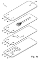
- FIG. 1a shows a static micromixer 1 with a cover plate 21, a mixer plate 20, a distributor plate 26 and a bottom plate 22 each separated from each other in a perspective view.
- the cover plate 21, the mixer plate 20 and the distributor plate 26 have a supply 23 for the fluid A and a supply 24 for the Fluid B in the form of a hole.
- the holes are arranged such that when stacking the plates, the feeds 23, 24 with the Feed structures 23, 24 of the bottom plate 22 fluidly in communication stand.
- the supply 23 for the fluid A and the supply 24 for the fluid B are arranged in the form of grooves on the bottom plate 22 such that the Fluid A to the manifold structure 27 and the fluid B to the manifold structure 28th the overlying distributor plate 26 without significant pressure losses can be directed.
- the distributor plate 26 has a distributor structure 27 for the fluid A and a distributor structure 28 for the fluid B in each case in the form a series of holes passing through the plate.
- the mixer plate 20 shown in detail in Figure 1 b in plan view has Fluid channels 2,3, an inlet chamber 4, a focusing channel 5 and a Expansion chamber 6 on.
- the discharge 25 in the form of a hole in the Cover plate 21 is arranged such that when stacking the plates the discharge 25 with the expansion chamber 6 of the mixer plate 20 fluidly communicates.
- the channels 2 for the fluid A have a smaller length as the channels 3 for the fluid B on.
- the channels 2, 3 are in their from the Inlet chamber 4 opposite side aligned parallel to each other, wherein the Channels 2 for the fluid A alternately adjacent to the channels 3 for the Fluid B lie. In a transition area, the distance of the Channels towards each other in the direction of inlet chamber 4.
- the channels 2, 3 In the area of Entrance into the inlet chamber 4, the channels 2, 3 in turn parallel aligned with each other. To ensure a uniform volume flow over all Channels 2, 3 for each to achieve a fluid, the channels 2, 3 respectively with each other the same length. This leads to that of the Entry chamber 4 remote ends of the fluid channels 2, 3 respectively to lie in a bow.
- the holes of the distributor structures 27,28 of Distributor plate 26 are also arranged in an arc in each case, that the ends of the channels 2, 3 each fluidly contacted with a bore become.
- the inlet chamber 4, in which the fluid channels 2, 3 open, points in the plane of the fluid channels on a half-concave shape.
- the concave surface 8 which the junctions of the fluid channels 2, 3rd opposite, the inlet chamber 4 is in the focusing channel 5 via.
- the focusing channel 5 opens into the expansion chamber 6, which of a wider in comparison with the focusing channel 5 and in Elongated to this arranged channel is formed.
- the structures of Fluid channels 2, 3, the inlet chamber 4, the focusing channel 5 and the Expansion chamber 6 are characterized by the material of the mixer plate 20th formed through openings. Through the underlying Distributor plate 26 and the overlying cover plate 21, these become two Side open structures forming channels or chambers covered.
- the united Fluid flows quickly transferred to the focusing channel 5.
- the thus formed focused total fluid flow is in the expansion chamber 6 as a fluid jet initiated.
- the formed mixture of fluids A, B is through which the discharge area of the expansion chamber 6 located exhaust hole 25th the cover plate 21 derived.
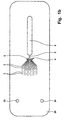
- FIG. 2 shows a mixer plate 20 in plan view, with the feeding ones Fluid channels 2,3 for the fluids A and B compared to Figure 1 b simplified are shown.
- the inlet chamber 4 has a semi-concave shape, wherein the concave surface 8 lies opposite the junctions of the channels 2, 3.
- the Inlet chamber 4 is in the region of the center of the concave surface 8 in the Focusing channel 5 via.
- the focusing channel 5 has over its entire Length equal to a width and opens into the expansion chamber 6 a.
- the Expansion chamber 6 is opposite to the focusing channel 5 in a further focusing channel 5 'which serves as outlet channel 7 via.
- the Expansion chamber 6 has a substantially circular in plan view Shape, which is widened in the direction of the further focusing channel 5 '. Due to this shape, the expansion chamber 6 has in its interior in the level shown adapted to the formation of stationary vertebrae Shape. This avoids dead water areas so that all areas of the Expansion chamber 6 are constantly flowed through
- the fluid streams of the fluids A and B emerging from the channels 2, 3 become merged in the inlet chamber 4 and, due to the schkonkave Form, quickly as a unified fluid lamella in the focusing channel. 5 transferred.
- Due to the much narrower cross section of the Focusing channel 5 compared to the inlet chamber 4 is a Focusing the fluid flow, i. a reduction in the fluid blade width achieved while increasing the flow rate.
- the so focused total fluid flow occurs as a fluid jet 5 in the expansion chamber. 6 and experiences there a lateral expansion, whereby on both sides of the Fluid jet can form vortices. That scored in the expansion chamber 6 Mixed product is re-focused in the further Focusing channel 5 'derived.
- the obtained fluid mixture is at the end of another focusing channel 5 'up into a above the mixer plate 20 located cover plate derived.
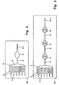
- the mixer plate 20 shown in plan view in Figure 3 has a series of a plurality of successively arranged expansion chambers 6, 6 ', 6 "and Focusing channels 5, 5 ', 5 ", 5'” on.
- the design and form of supplying fluid channels 2, 3, the inlet chamber 4, the focusing channel 5 and the expansion chamber 6 are equal to the corresponding structures the mixer plate previously shown in Figure 2.
- the expansion chamber 6 goes opposite the focusing channel 5 in another Focusing channel 5 'across, extending in the longitudinal extension of the Focusing channel 5 is located.
- This further focusing channel 5 ' opens turn into another vortex chamber 6 ', which in turn into a is followed by a further focusing channel 5 '" Expansion chamber 6 '", which finally serving as the outlet 7 the focusing channels 5, 5 ', 5 ", 5 “'have a substantially equal length and are in Longitudinal extension to each other with expansion chambers in between 6, 6 ', 6 "are arranged in the expansion chambers 6, 6', 6" of the fluid jet indicated by an arrow. On both sides of the fluid jet here formed by helical lines indicated steady vortex.
- the arranged behind an expansion chamber focusing channel detected thus at least part of the entering into the expansion chamber Fluid jet as well as a part of the obtained mixed product.
- the mixer plate 20 of another invention static micromixer shown in plan view.
- two Feed channels 9a, 9b In the expansion chamber 6 open on the side in which the Focusing channel 5 enters, and arranged symmetrically thereto, two Feed channels 9a, 9b.
- these feed channels 9a, 9b can in the area the formed vortex in the expansion chamber 6 another fluid, For example, be initiated an emulsifier.
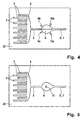
- FIG. 5 shows a plan view of a mixer plate 20 of another static micromixer according to the invention having structures as in FIG. 2 shown, wherein additionally in the expansion chamber 6, a baffle structure 11th located.
- the baffle structure 11 is characterized by a in the expansion chamber. 6 formed cuboid structure, wherein one surface of the cuboid Opposite and spaced to the junction of the focusing channel. 5 located. This ensures that the fluid jet in the Expansion chamber 6 exiting focused total fluid flow on the Impingement 11 meets and there under vortex formation on both sides in the Expansion chamber 6 is derived. This is a particularly intimate Mixture achieved with very short mixing times.
- the formed mixture becomes via the further focusing channel 5 'serving as outlet channel 7 derived.
- a mixer plate 20 of a further embodiment of the invention static micromixer is shown in Figure 6 in plan view.
- the Arrangement of the fluid channels 2, 3, the inlet chamber 4 and the Focusing channel 5 corresponds to the figure 2.
- the focusing channel 5 goes in an expansion chamber 6 on, in the plane shown no Outlet channel has.
- the expansion chamber 6 points in the plane shown a substantially round shape, wherein the focusing channel. 5 opposite surface is arched into the expansion chamber. This ensures that the from the focusing channel 5 in the Expansion chamber 6 exiting fluid jet to the area of bulged Surface, which serves as a baffle structure 11, meets and on both sides in the Expansion chamber 6 is derived.
- the mixture thus obtained is through a located in the cover plate not shown outlet duct 7, which is shown here as a circle with a dashed line.
- FIG. 7 shows a variant of the mixer plate 20 of FIG. 6 illustrated static micromixer. Also here has the Expansion chamber 6 a through an area bulged in the chamber the wall of the expansion chamber 6 formed baffle structure 11. In the Expansion chamber 6 open two outlet channels 10a, 10b. These Outlet channels are located substantially opposite the Baffle structure 11 and are symmetrical to the axis of the focusing channel fifth arranged. Compared to Figure 6, the obtained mixture is thus not upward from the expansion chamber but laterally from the areas of the Vortex formation derived.
- FIG. 8 shows a variant of the embodiment shown in FIG shown.
- the expansion chamber 6 open in addition to the other Outlet channels 10a, 10b two supply channels 9a, 9b.
- These feed channels are on both sides of the baffle structure 11 and adjacent thereto as well symmetrical to the axis formed by the focusing channel 5 arranged.
- these feed channels can be the Supplying a mixture, in particular the emulsion or dispersion, supporting fluid, for example, the supply of an emulsifier, serve.
- the further outlet channels 10a, 10b and the feed channels 9a, 9b stand with appropriate feed or outlet structures in the soil and / or or cover plate in fluid communication.
- a mixer plate 20 of another embodiment of the static Micromixer is shown in Figure 9 in plan view.
- a common expansion chamber 16 open opposite of two sides two focusing channels 5, 15 a.
- These focusing channels 5, 15 are in Connection in each case with an inlet chamber 4, 14, in which the fluid channels 2,3; 12,13 lead.
- the two focusing channels 5, 15 are in Longitudinal extension arranged to each other. Perpendicular to this and in the same Level opens on both sides of an outlet 10 a, 10 b in the Expansion chamber 16.
- Both in the inlet chamber 4 and in the Inlet chamber 14 are from the fluid channels 2,3; 12,13 exit Fluid streams combined and rapidly focused into the focusing channel 5, 15 headed.
- the so united and focused fluid lamellae occur from the focusing channels 5,15 each as a fluid jet of on opposite sides in the common expansion chamber 16 and meet there under vortex formation on each other, which in a short time a intimate mixture is achieved.
- the obtained mixed product becomes on both sides from the common expansion chamber 16 via the outlet channels 10a, 10b, those with corresponding structures in the bottom and / or top plate fluidically derived.
- the static micromixer shown in Figures 1 a and 1 b was realized by means of microstructured glass plates.
- the mixer plate 20 and the Distributor plate 26 each had a thickness of 150 microns and the final bottom plate 22 and cover plate 21 each have a thickness of 1 mm up.
- the mixer plate 20th and the distributor plate 26 were holes with a diameter of 1.6 mm selected.
- the distributor plate 26 had two distributor structures 27, 28 Rows of 15 slots each with a length of 0.6 mm and a width of 0.2 mm.
- the fluid channels 2, 3 of the mixer plate 20 had a width of 60 microns at a length of 11.3 mm and a length of 7.3 mm.
- the distance between the junction of the Fluid channels 2, 3 and the mouth of the focusing channel 5 was only 2.5 mm, to rapidly divert and focus the combined fluid streams to enable.
- the ratio of the cross sectional area of the Focusing channel to the sum of the cross-sectional areas of the Fludikanäle 2, 3 was 1 to 3.6. With a length of 2.5 mm of the focusing channel 5, a length to width ratio of 5 to 1 was achieved.
- the Focusing channel 5 went in the longitudinal direction in the channel-like design Expansion chamber 6 a length of 24.6 mm and a width of 2.8 mm above.
- the opening angle of the side surfaces of the expansion chambers 6 in Transition region between the expansion chamber 6 and the Focusing channel 5 was 126.7 °.
- the four shown in the figure 1 a Plates had an external dimension of 26 x 76 mm.
- the plates were photolithographically using photoimageable glass by means of of a known method, as described by Th. R. Dietrich, W. Ehrfeld, M. Lacher and B. Speit in microstructure products photoimageable glass, F & M 104 (1996) on pages 520 to 524 has been described.
- the plates became fluid by thermal bonding tightly connected.
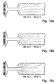
- FIGS. 10 a to 10 c only show the detail the junctions of the fluid channels 2, 3 in the inlet chamber 4, the Focusing channel 5 and the expansion chamber. 6
- the fluidized channels carrying the dye-added water are in the left entry area into the inlet chamber at its darker gray tone clearly visible. Since both the supplied silicone oil and the between the fluid channels 2, 3 existing webs of glass are transparent, These are not distinguishable here.
Abstract
Description
Die Erfindung betrifft ein Verfahren und einen statischen Mikrovermischer zum Mischen mindestens zweier Fluide.The invention relates to a method and a static micromixer for mixing at least two fluids.
Ziel beim Mischen mindestens zweier Fluide ist das Erreichen einer gleichförmigen Verteilung der beiden Fluide in einer bestimmten, in der Regel möglichst kurzen Zeit. Hierzu werden Mischvorgänge mit einem hohen spezifischen Energieeintrag angestrebt. Von Vorteil sind Mischvorgänge mit gerichteten Strömungen, die die stattfindenden Mischprozesse unter Zuhilfenahme von Modellbetrachtungen vorhersagbar machen. Besonders vorteilhaft werden hierzu statische Mikrovermischer eingesetzt, wie sie in der Übersicht von W. Ehrfeld, V. Hessel, H. Löwe in Microreactors, New Technology for Modern Chemistry, Wiley-VCH 2000, Seiten 41 bis 85 dargestellt sind. Mit bekannten statischen Mikrovermischern werden durch Erzeugen abwechselnd benachbarter Fluidlamellen einer Stärke im µm-Bereich Mischzeiten zwischen 1 s und wenigen Millisekunden erzielt. Im Gegensatz zu dynamischen Mischern, in denen turbulente Strömungsverhältnisse vorherrschen, wird durch die vorgegebene Geometrie ein exaktes Einstellen der Breite der Fluidlamellen und damit der Diffusionswege ermöglicht. Die hierdurch erzielte sehr enge Verteilung der Mischzeiten erlaubt vielfältige Möglichkeiten der Optimierung von chemischen Umsetzungen im Hinblick auf Selektivität und Ausbeute. Ein weiterer Vorteil von statischen Mikrovermischern ist die Miniaturisierung und damit Integrierbarkeit in weitere Systeme, wie Wärmetauscher und Reaktoren. Die Anwendungspotenziale umfassen Flüssig-Flüssig und Gas-Gas Mischungen, einschließlich Reaktionen in den entsprechenden Regimen, sowie Flüssig-Flüssig Emulsionen, Gas-Flüssig Dispersionen, Fest-Flüssig-Dispersionen und damit auch Mehrphasen- und Phasentransfer-Reaktionen, Extraktionen und Absorption.The goal in mixing at least two fluids is to achieve a uniform distribution of the two fluids in a given, as a rule as short a time as possible. For this purpose, mixing operations with a high targeted energy input. Of advantage are mixing processes with directed currents that underlie the mixing processes taking place Make predictive use of model considerations. Especially For this purpose, static micromixers are advantageously used, as used in the Overview by W. Ehrfeld, V. Hessel, H. Leo in Microreactors, New Technology for Modern Chemistry, Wiley-VCH 2000, pages 41 to 85 are shown. With known static micromixers are by Generating alternately adjacent fluid lamellae of a thickness in the micron range Mixing times between 1 s and a few milliseconds achieved. In contrast to dynamic mixers, in which turbulent flow conditions prevail, is by the given geometry an exact setting the width of the fluid fins and thus allows the diffusion paths. The This achieved very narrow distribution of mixing times allowed diverse Possibilities of optimizing chemical reactions with regard to Selectivity and yield. Another advantage of static Micromixing is the miniaturization and thus integrability in other systems, such as heat exchangers and reactors. The Application potential includes liquid-liquid and gas-gas mixtures, including reactions in the respective regimens, as well as liquid-liquid Emulsions, gas-liquid dispersions, solid-liquid dispersions and thus also multiphase and phase transfer reactions, extractions and Absorption.
Ein nach dem Prinzip der Multilamination arbeitender statischer Mikrovermischer weist in einer Ebene eine mikrostrukturierte Interdigitalstruktur aus ineinandergreifenden Kanälen einer Breite von 25 µm oder 40 µm auf (a. a. O. Seite 64 bis 73). Die beiden zu mischenden Fluide werden durch die Kanäle in eine Vielzahl voneinander getrennter Fluidströme aufgeteilt, die entgegengesetzt parallel zueinander strömend und alternierend zueinander angeordnet sind. Durch einen Schlitz werden die benachbarten Fluidströme senkrecht aus der Ebene nach oben abgeführt und miteinander kontaktiert. Mittels für die Massenfertigung geeigneter Strukturierungsverfahren lassen sich die Kanalgeometrien und damit die Fluidlamellenbreite nur begrenzt bis in den unteren µm-Bereich reduzieren.A working according to the principle of Multilamination static Micromixer has a microstructured in a plane Interdigital structure of intermeshing channels of a width of 25 microns or 40 μm (see above, pages 64 to 73). The two fluids to be mixed pass through the channels into a plurality of separate fluid streams divided, the opposite parallel to each other and flowing alternately are arranged to each other. Through a slot, the neighboring Fluid flows discharged vertically from the plane upwards and with each other contacted. By means suitable for mass production Structuring methods can be the channel geometries and thus the Reduce fluid lamella width only limited to the lower μm range.
Eine weitere Reduzierung der nach dem Multilaminationsprinzip erhaltenen Fluidlamellen kann durch sogenanntes hydrodynamisches Fokussieren erzielt werden. Solch ein statischer Mikrovermischer zum Umsetzen gefährlicher Stoffe wird von T. M. Floyd et al. auf den Seiten 171 bis 179 in Microreaction technology: industrial prospects; proceedings of the Third International Conference on Microreaction Technology/ IMRET3, editor: W. Ehrfeld, Springer 2000 vorgestellt. Abwechselnd benachbarte Kanäle für die beiden zu mischenden Fluide münden in einem Halbkreis radial von außen in eine trichterförmig ausgezogene und in einen engen, langen Kanal übergehende Kammer. Der in der Kammer vereinigte Fluidlamellenstrom wird hierbei in den engen Kanal überführt, wodurch eine Verkleinerung der Fluidlamellenbreite stattfindet. Auch bei reduzierten Lamellenbreiten im unteren µm-Bereich werden durch Diffusion bedingte Mischzeiten im Millisekundenbereich erhalten, was für einige Anwendungen, insbesondere ultra-schnelle Reaktionen, noch zu lang ist. Zudem weist dieser Mikrovermischer bedingt durch den langen, als Reaktionsraum dienenden Kanal eine große Bauform auf.A further reduction of the obtained according to the multilamination principle Fluid lamellae can be achieved by so-called hydrodynamic focusing become. Such a static micromixer to implement dangerous Fabrics are described by T. M. Floyd et al. on pages 171 to 179 in Microreaction technology: industrial prospects; proceedings of the third International Conference on Microreaction Technology / IMRET3, editor: W. Ehrfeld, Springer 2000 presented. Alternate adjacent channels for the both fluids to be mixed open in a semicircle radially from the outside in a funnel-shaped extended and merging into a narrow, long channel Chamber. The combined in the chamber fluid laminar flow is in this case transferred the narrow channel, causing a reduction of the Fluid lamella width takes place. Even with reduced slat widths in the The lower μm range is due to diffusion-related mixing times in the Millisecond range, which is true for some applications, in particular ultra-fast reactions, too long. In addition, this one has Micromixer due to the long, serving as a reaction space Channel a large design.
Die Erfindung hat zur Aufgabe ein Verfahren und einen statischen Mikrovermischer zum Mischen mindestens zweier Fluide zur Verfügung zu stellen, die ein schnelles Mischen der Fluide bei hoher Mischgüte und kleinem Bauraum ermöglichen.The invention has for its object a method and a static Micromixer for mixing at least two fluids available provide a fast mixing of the fluids with high mixing quality and small Allow space.
Die Aufgabe wird erfindungsgemäß mit einem Verfahren gemäß Anspruch 1
und einem statischen Mikrovermischer gemäß Anspruch 10 gelöst.The object is achieved by a method according to
Nachfolgend wird unter dem Begriff Fluid ein gasförmiger oder flüssiger Stoff oder ein Gemisch solcher Stoffe verstanden, das einen oder mehrere feste, flüssige oder gasförmige Stoffe gelöst oder dispergiert enthalten kann.Hereinafter, the term fluid is a gaseous or liquid substance or a mixture of such substances having one or more solid, may contain liquid or gaseous substances dissolved or dispersed.
Der Begriff Mischen umfasst auch die Vorgänge Lösen (Blenden), Dispergieren, Emulgieren und Suspendieren. Demzufolge umfasst der Begriff Mischung Lösungen, Flüssig-Flüssig-Emulsionen, Gas-Flüssig und Fest-Flüssig-Dispersionen.The term mixing also includes the processes dissolving (blending), Dispersing, emulsifying and suspending. Consequently, the term includes Mixture solutions, liquid-liquid emulsions, gas-liquid and solid-liquid dispersions.
Unter einer Vielzahl von Fluidströmen oder Fluidkanälen werden je Fluid zwei oder mehr, vorzugsweise drei oder mehr, besonders bevorzugt fünf oder mehr, Fluidströme bzw. Fluidkanäle verstanden. Abwechselnd benachbarte Fluidlamellen oder Fluidkanäle bedeutet bei zwei Fluiden A, B, dass diese in mindestens einer Ebene alternierend, eine Reihenfolge von ABAB ergebend, nebeneinander liegen. Der Begriff "abwechselnd benachbart" umfasst bei drei Fluiden A, B, C unterschiedliche Reihenfolgen, wie beispielsweise ABCABC oder ABACABAC. Die Fluidlamellen oder Fluidkanäle können auch in mehr als einer Ebene abwechselnd benachbart liegen, beispielsweise in zwei Dimensionen schachbrettartig zueinander versetzt liegen. Die den unterschiedlichen Fluiden zugehörigen Fluidströme und Fluidkanäle sind vorzugsweise gleichgerichtet oder entgegengerichtet parallel zueinander angeordnet.Among a plurality of fluid streams or fluid channels, two are provided for each fluid or more, preferably three or more, more preferably five or more, Fluid flows or fluid channels understood. Alternately adjacent Fluid lamellae or fluid channels in the case of two fluids A, B mean that they are in alternating at least one level, resulting in an order of ABAB, lie next to each other. The term "alternately adjacent" includes three Fluids A, B, C have different orders, such as ABCABC or ABACABAC. The fluid fins or fluid channels can also be in more are alternately adjacent as one plane, for example in two Dimensions are arranged like a checkerboard to each other. The the different fluid associated fluid flows and fluid channels preferably rectified or oppositely parallel to each other arranged.
Das erfindungsgemäße Verfahren zum Mischen von mindestens zwei Fluiden umfasst mindestens vier Verfahrensschritte. Im 1. Schritt wird eine Vielzahl getrennter Fluidströme der beiden Fluide jeweils einer Breite im Bereich von 1 µm bis 1 mm und einer Tiefe im Bereich von 10 µm bis 10 mm zusammengeführt, wobei sich abwechselnd benachbarte Fluidlamellen der beiden Fluiden bilden. Im 2. Schritt werden die so vereinigten Fluidströme unter Ausbildung eines fokussierten Gesamtfluidstroms abgeführt. Im 3. Schritt wird der so erhaltene Gesamtfluidstrom als Fluidstrahl in eine Expansionskammer mit einer zum fokussierten Gesamtfluidstrom größeren Querschnittsfläche senkrecht zur Strömungsrichtung des fokussierten Gesamtfluidstroms eingeleitet. Im letzten Verfahrensschritt wird die so gebildete Mischung abgeleitet.The inventive method for mixing at least two fluids comprises at least four process steps. In the 1st step will be a variety separate fluid flows of the two fluids each having a width in the range of 1 μm to 1 mm and a depth in the range of 10 μm to 10 mm merged, wherein alternately adjacent fluid fins of the form two fluids. In the second step, the so-combined fluid flows dissipated to form a focused total fluid flow. In the third step is the total fluid flow thus obtained as a fluid jet in a Expansion chamber with a larger to the focused total fluid flow Cross-sectional area perpendicular to the flow direction of the focused Total fluid flow initiated. In the last step of the process, the like derived mixture formed.
Das Zusammenführen erfolgt derart, dass die zunächst getrennten Fluidströme in einen Raum einströmen. Hierbei können die Fluidströme parallel zueinander oder ineinanderführend, beispielsweise radial nach innen, ausgerichtet sein. Beim Zusammenführen bilden sich Fluidlamellen aus, deren Querschnittsflächen zunächst denen der Fluidströme entsprechen. Durch das Abführen als fokussierter Gesamtfluidstrom findet eine Reduzierung der Breite und / oder der Querschnittsfläche der Fluidlamellen statt, bei gleichzeitiger Erhöhung der Fließgeschwindigkeit. Der so beschleunigte fokussierte Gesamtfluidstrom wird als Fluidstrahl (Jet) in die Expansionskammer eingeleitet. Durch das Aufweiten der Fluidlamellen in der Expansionskammer treten senkrecht zur Hauptströmung gerichtete Kräfte (Scherkräfte) auf, die im Vergleich mit alleiniger diffusiver Mischung kürzere Mischzeiten erzielen lassen. Insbesondere der Prozess der Fragmentierung in einzelne Teilchen als diskontinuierliche Phase in einer kontinuierlichen Phase und damit die Bildung von Emulsionen und Dispersionen wird vorteilhaft beeinflusst. Von besonderem Vorteil ist hierbei die Wirkung des Fluidstrahls als Saug- und Schleppstrahl sowie das Auftreten gerichteter Wirbel.The merging takes place in such a way that the initially separate fluid streams pour into a room. In this case, the fluid streams can be parallel to each other or in one another, for example radially inward, be aligned. When merging fluid lamellae form, whose Cross-sectional areas initially correspond to those of the fluid flows. By the Discharge as a focused total fluid flow finds a reduction in width and / or the cross-sectional area of the fluid fins, while at the same time Increase the flow rate. The so accelerated focused Total fluid flow is as a jet of fluid (jet) in the expansion chamber initiated. By the expansion of the fluid fins in the expansion chamber occur perpendicular to the main flow directed forces (shear forces), which in the Comparison with only diffusive mixture to achieve shorter mixing times to let. In particular, the process of fragmentation into individual particles as discontinuous phase in a continuous phase and thus the formation of emulsions and dispersions is favorably influenced. From particular advantage here is the effect of the fluid jet as suction and Towing jet and the occurrence of directed vortex.
Bevorzugt werden die vereinigten Fluidströme derart fokussiert, dass das Verhältnis der Querschnittsfläche des fokussierten Gesamtfluidstroms zu der Summe der Querschnittsflächen der zusammenzuführenden Fluidströme jeweils senkrecht zur Strömungsrichtung im Bereich von 1 zu 1,5 bis 1 zu 500, vorzugsweise im Bereich von 1 zu 2 bis 1 zu 50, liegt. Je kleiner das Verhältnis ist, desto stärker wird die Lamellenbreite reduziert und desto stärker wird die Fließgeschwindigkeit erhöht, mit der der fokussierte Gesamtfluidstrom als Fluidstrahl in die Expansionskammer eingeleitet wird. Vorteilhaft weist der fokussierte Gesamtfluidstrom einen über seine Länge gleichbleibenden Querschnitt auf. Denkbar ist auch eine in Richtung der Expansionskammer abnehmende Querschnittsfläche, wobei obiges Verhältnis für den Bereich mit kleinster Querschnittsfläche gilt.Preferably, the combined fluid streams are focused such that the Ratio of the cross-sectional area of the focused total fluid flow to the Sum of the cross-sectional areas of the fluid flows to be merged in each case perpendicular to the flow direction in the range of 1 to 1.5 to 1 to 500, preferably in the range of 1 to 2 to 1 to 50. The smaller that Ratio is, the more the slat width is reduced and the stronger the flow rate is increased with which the focused total fluid flow is introduced as a fluid jet into the expansion chamber. Advantageously, the focused total fluid flow over its length consistent Cross-section on. It is also conceivable in the direction of the expansion chamber decreasing cross-sectional area, the above ratio for the area with smallest cross-sectional area applies.
Bevorzugt liegt das Verhältnis der Länge des fokussierten Gesamtfluidstroms zu seiner Breite im Bereich von 1 zu 1 bis 30 zu 1, vorzugsweise im Bereich 1,5 zu 1 bis 10 zu 1. Hierbei soll der fokussierte Gesamtfluidstrom möglichst ausreichend lang sein, um eine ausreichend fokussierende Wirkung unter Beibehaltung der laminaren Strömungsverhältnisse zu erzwingen. Jedoch sollte der fokussierte Gesamtfluidstrom kurz ausgebildet werden, um im Hinblick auf eine kurze Mischzeit den Gesamtfluidstrom möglichst rasch als Fluidstrahl in die Expansionskammer einleiten zu können.Preferably, the ratio of the length of the focused total fluid flow to its width in the range of 1 to 1 to 30 to 1, preferably in the range 1.5 to 1 to 10 to 1. Here, the focused total fluid flow as possible be sufficiently long to have a sufficient focusing effect To maintain the laminar flow conditions. However, should the focused total fluid flow is made short in order to obtain a short mixing time the total fluid flow as quickly as a fluid jet in to initiate the expansion chamber.
Vorteilhaft wird der fokussierte Gesamtfluidstrom derart als Fluidstrahl in den Expansionskammer eingeleitet, dass sich zumindestens in einer Ebene, vorzugsweise zu beiden Seiten des Fluidstrahls Wirbel, insbesondere stationäre Wirbel, bilden. Solche stationären Wirbel bilden sich besonders in den Bereichen aus, entlang derer der Fluidstrahl vorbeiströmt und diese Bereiche zur Rotation bringt. Bevorzugt wird der Fluidstrahl symmetrisch in den Raum eingeleitet, so dass sich zumindestens in einer Ebene zu beiden Seiten stationäre Wirbel ausbilden. Ist die Expansionskammer im Vergleich zum fokussierten Gesamtfluidstrom nicht nur in der Breite, sondern über den gesamten Querschnitt aufgeweitet, so ist es von besonderem Vorteil, wenn sich allseitig um den Fluidstrahl stationäre Wirbel bilden. Durch die in den stationären Wirbeln auftretenden Scherkräfte bei zumindest teilweise turbulenten Strömungsbedingungen wird der Mischvorgang positiv beeinflusst. Von Vorteil ist die Expansionskammer hierbei so ausgebildet, dass die Wirbel nicht in sogenannten Totwasserbereichen, sondern in durchflossenen Bereichen gebildet werden.Advantageously, the focused total fluid flow is as a fluid jet in the Expansion chamber initiated that at least in one plane, preferably on both sides of the fluid jet vortex, in particular stationary Vortex, form. Such stationary vortices are formed especially in the From areas along which the fluid jet flows past and these areas brings to rotation. Preferably, the fluid jet is symmetrical in the room initiated, so that at least in one plane to both sides train stationary vertebrae. Is the expansion chamber compared to focused total fluid flow not only in width, but over the expanded cross-section, so it is of particular advantage when form stationary vortexes all around the fluid jet. By in the stationary vertebrae occurring shear forces at least partially turbulent flow conditions, the mixing process is positively influenced. Advantageously, the expansion chamber is designed so that the vortex not in so-called dead water areas, but in areas that are traversed be formed.
Gemäß einer Ausführungsform wird zumindest ein Teil des Fluidstroms nach dem Einleiten in die Expansionskammer erneut unter Fokussierung abgeleitet. Dies kann den gesamten aus der Expansionskammer austretenden Fluidstrahl umfassen oder nur einen Teil hiervon, wobei der andere Teil vorteilhaft als fertige Mischung abgeleitet wird. Ein Vorteil durch das erneute Fokussieren ist, dass eine weitere Kontaktierung von Bereichen stattfindet, die noch nicht vollständig gemischt sind. Vorteilhaft wird hierbei der fokussierte Fluidstrom als Fluidstrahl erneut unter Wirbelbildung in eine weitere Expansionskammer eingeleitet.According to one embodiment, at least a part of the fluid flow is after re-focussed upon introduction into the expansion chamber. This can be the entire fluid jet exiting the expansion chamber comprise or only a part thereof, the other part being advantageous as finished mixture is derived. An advantage of re-focusing is that further contacting of areas is taking place, not yet are completely mixed. In this case, the focused fluid flow is advantageous as a fluid jet again with vortex formation in a further expansion chamber initiated.
Gemäß einer weiteren Ausführungsform werden die folgenden beiden Verfahrensschritte ein oder mehrfach wiederholt. Im ersten dieser beiden Verfahrensschritte wird zumindest ein Teil des Fluidstroms nach dem vorhergehenden Einleiten in die Expansionskammer unter Ausbildung eines fokussierten Fluidstroms abgeführt. Im zweiten Schritt wird der fokussierte Fluidstrom in eine weitere Expansionskammer eingeleitet, die eine zum fokussierten Fluidstrom größere Querschnittsfläche senkrecht zur Strömungsrichtung des fokussierten Fluidstroms aufweist. Nach dem ein oder mehrfachen Durchführen dieser beiden Schritte wird die gebildete Mischung abgeleitet. Durch das wiederholte Durchführen von Fokussieren und Einleiten in eine Expansionskammer wird ein besonders intensives Mischen erzielt, was insbesondere bei der Bildung von Emulsionen und Dispersionen mit kleinen Teilchengrößen von Vorteil ist. Bezüglich der vorteilhaften Durchführung des Fokussierens und des Einleitens wird auf die angeführten bevorzugten Varianten hingewiesen.According to another embodiment, the following two Procedural steps one or more times. In the first of these two Process steps will be at least part of the fluid flow after previous introduction into the expansion chamber to form a fanned fluid flow dissipated. In the second step, the focused Fluid stream is introduced into a further expansion chamber, which is a for focused fluid flow greater cross-sectional area perpendicular to Having flow direction of the focused fluid flow. After the one or Repeatedly performing these two steps becomes the formed mixture derived. By repeatedly focusing and initiating in an expansion chamber a particularly intense mixing is achieved, which especially in the formation of emulsions and dispersions with small Particle sizes is beneficial. With regard to the advantageous implementation of the Focusing and initiating will be to the preferred ones Variants pointed out.
Vorteilhaft wird in die Expansionskammer ein weiteres Fluid eingeleitet. Das Einleiten kann an einer oder mehreren Stellen, die vorzugsweise symmetrisch zu dem Fluidstrahl liegen, durchgeführt werden. Das weitere Fluid kann einen die Mischung stabilisierenden Hilfsstoff, beispielsweise einen Emulgator, aufweisen.Advantageously, another fluid is introduced into the expansion chamber. The Initiation can occur at one or more points, preferably symmetrically to the fluid jet. The other fluid can one the mixture stabilizing adjuvant, for example an emulsifier, exhibit.
Vorteilhaft wird zumindest ein Teil der gebildeten Mischung aus dem oder den Bereichen der Expansionskammer mit Wirbelbildung abgeleitet. Hierbei kann die gebildete Mischung in einen oder mehreren Strömen, die vorzugsweise symmetrisch zum Fluidstrahl liegen, abgeleitet werden. Hierbei erfolgt besonders vorteilhaft das Ableiten aus den Bereichen der stationären Wirbel, in denen eine Mischung hoher Mischgüte vorliegt.At least a portion of the resulting mixture of the one or more is advantageous Regions of the expansion chamber derived with vortex formation. Here can the formed mixture into one or more streams, preferably are symmetrical to the fluid jet, are derived. This takes place deriving from the areas of the stationary vortex, in which is a mixture of high mixing quality.
Entsprechend einer bevorzugten Ausführungsform wird der fokussierte Gesamtfluidstrom auf eine sich in der Expansionskammer befindliche Struktur, die den Fluidstrahl ablenkt, geleitet. Diese Prallstruktur kann eine ebene oder gebogene Fläche oder eine Struktur zum Ablenken und/ oder Aufspalten des Fluidstrahls sein. Ebenso kann die der Einmündung des Fokussierungskanals gegenüberliegende Wand der Expansionskammer so ausgebildet sein, dass diese als Prallstruktur dient. Bei dieser Ausführungsform werden extrem hohe spezifische Energiedichten unter Verwendung eines vorlaminierten und fokussierten Gesamtfluidstroms und damit ein hoher Grad an Turbulenz erzielt. According to a preferred embodiment, the focused Total fluid flow to a structure located in the expansion chamber, which deflects the fluid jet, passed. This baffle structure can be a plane or curved surface or a structure for deflecting and / or splitting the Be fluid jet. Likewise, that of the mouth of the focusing channel opposite wall of the expansion chamber be designed so that this serves as a baffle structure. In this embodiment, extremely high specific energy densities using a prelaminated and focused total fluid flow and thus achieved a high degree of turbulence.
Die hohe Turbulenz führt zur Bildung kleiner Wirbel die aufgrund der auftretenden hohen Scherkräfte zu sehr kleinen Teilchendurchmessern, beispielsweise Tröpfchendurchmesser bei Emulsionen, führt. Im Gegensatz zu bekannten Verfahren ist eine Bildung von Voremulsionen nicht erforderlich.The high turbulence leads to the formation of small vortices due to the occurring high shear forces to very small particle diameters, for example, droplet diameter in emulsions leads. In contrast to known methods, formation of pre-emulsions is not required.
Gemäß einer weiteren Ausführungsform werden die ersten beiden Verfahrensschritte jeweils gleichzeitig und räumlich voneinander getrennt zweioder mehrfach durchgeführt. Hierdurch werden entsprechend zwei oder mehr fokussierte Gesamtfluidströme erhalten, die in eine gemeinsame Expansionskammer eingeleitet werden. Besonders vorteilhaft werden hierbei die fokussierten Gesamtfluidströme als Fluidstrahl derart in die gemeinsame Expansionskammer eingeleitet, dass diese aufeinander treffen, d. h. miteinander kollidieren. Die einzuleitenden Gesamtfluidströme können die gleichen Fluide oder auch unterschiedliche Fluide aufweisen, die dann erst in dem gemeinsamen Raum kontaktiert und gemischt werden. Hier können sich, wie zuvor beschrieben, weitere Schritte wie erneutes Fokussieren und Einleiten als Fluidstrahl in eine Expansionskammer anschließen. Wie bei der vorherigen Ausführungsform unter Verwendung einer Prallstruktur werden extrem hohe spezifische Energiedichten unter Verwendung zweier oder mehrerer vorlaminierter und fokussierter Gesamtfluidströme und damit ein hoher Grad an Turbulenz erzielt, wodurch insbesondere bei Suspensionen, Dispersionen und Emulsionen sehr kleine Teilchendurchmesser erhalten werden.According to another embodiment, the first two Process steps in each case simultaneously and spatially separated two or performed several times. As a result, two or more accordingly focused total fluid flows obtained in a common Expansion chamber to be initiated. Particularly advantageous here the focused total fluid streams as a fluid jet in the common Expansion chamber initiated that these meet, d. H. collide with each other. The total fluid flows to be introduced may be the have the same fluids or different fluids, which then only in contacted and mixed in the common room. Here can, as described above, take further steps such as re-focusing and initiating connect as fluid jet in an expansion chamber. As with the previous one Embodiment using a baffle structure becomes extremely high specific energy densities using two or more prelaminated and focused total fluid flows and thus a high degree achieved in turbulence, which in particular in suspensions, dispersions and emulsions are obtained very small particle diameter.
Der erfindungsgemäße statische Mikrovermischer zum Mischen mindestens zweier Fluide weist eine Vielzahl abwechselnd benachbarter Fluidkanäle, eine Einlasskammer, einen Fokussierungskanal, eine Expansionskammer und einen Auslasskanal zum Ableiten der gebildeten Mischung auf. Die Vielzahl abwechselnd benachbarter Fluidkanäle weist eine Breite im Bereich von 1 µm bis 1 mm und eine Tiefe im Bereich von 10 µm bis 10 mm zur getrennten Zuführung der Fluide als Fluidströme auf. Die Einlasskammer, in die die Fluidkanäle einmünden, dient dem Zusammenführen der Vielzahl getrennter Fluidströme der beiden Fluide. Der Fokussierungskanal ist zum Abführen der in der Einlasskammer vereinigten Fluidströme unter Ausbildung eines fokussierten Gesamtfluidstroms fluidisch mit der Einlasskammer verbunden. Die Expansionskammer, in die der Fokussierungskanal einmündet und der fokussierte Gesamtfluidstrom als Fluidstrahl eintritt, weist eine zum Fokussierungskanal größere Querschnittsfläche senkrecht zur Achse des Fokussierungskanals auf. Der mindestens eine mit der Expansionskammer fluidisch in Verbindung stehende Auslasskanal dient zum Ableiten der gebildeten Mischung.The inventive static micromixer for mixing at least two fluids has a plurality of alternately adjacent fluid channels, a Inlet chamber, a focusing channel, an expansion chamber and a Outlet channel for discharging the mixture formed. The variety alternately adjacent fluid channels has a width in the range of 1 micron to 1 mm and a depth in the range of 10 microns to 10 mm to separate Supplying the fluids as fluid streams. The inlet chamber into which the Open fluid channels, serves the merging of the plurality of separate Fluid flows of the two fluids. The focusing channel is for discharging the in the inlet chamber combined fluid streams to form a focused total fluid flow fluidly connected to the inlet chamber. The expansion chamber into which the focusing channel opens and the focused total fluid stream enters as a fluid jet, has a Focusing channel larger cross-sectional area perpendicular to the axis of the Focusing channel on. The at least one with the expansion chamber fluidically connected outlet channel serves to derive the formed mixture.
Vorzugsweise weist die Einlasskammer in Ihrem Innern zumindest in einer Ebene eine konkave oder halb konkave Form auf, wobei die konkave Fläche, in der der Fokussierungskanal mittig einmündet, der Fläche, in die die Fluidkanäle einmünden, gegenüber liegt. Durch die konkave Form wird ein rasches Zusammenführen und Abführen in den Fokussierungskanal unter Erhalt der Fluidlamellen erreicht. Es ist jedoch auch denkbar, die vereinigten Fluidströme allmählich auf den Fokussierungskanal zuzuführen, wozu die Einlasskammer in zumindest einer Ebene dreieckförmig-zulaufend oder trichterförmig ausgebildet ist.Preferably, the inlet chamber in its interior at least in one Level a concave or semi-concave shape, with the concave surface, in which the focusing channel opens in the middle, the surface into which the Open fluid channels, opposite lies. The concave shape becomes one rapid merging and removal into the focusing channel while preserving reaches the fluid fins. However, it is also conceivable that united Gradually supply fluid streams to the focusing channel, including the Inlet chamber in at least one plane triangular-tapered or funnel-shaped.
Im Sinne einer einfachen technischen Realisierung ist es von Vorteil, wenn die Fluidkanäle, die Einlasskammer, der Fokussierungskanal und / oder die Expansionskammer die gleiche Tiefe aufweisen. Hierbei ist es ebenfalls von Vorteil, wenn die Einmündungen der Fluidkanäle zumindest im Bereich der Einlasskammer in einer Ebene liegen.In the sense of a simple technical realization, it is advantageous if the Fluid channels, the inlet chamber, the focusing channel and / or the Expansion chamber have the same depth. Here it is also from Advantage, when the junctions of the fluid channels at least in the range of Inlet chamber lie in a plane.
Bevorzugt ist der Fokussierungskanal derart ausgebildet, dass das Verhältnis der Querschnittsfläche des Fokussierungskanals zu der Summe der Querschnittsflächen der in die Einlasskammer einmündenden Fluidkanäle jeweils senkrecht zur Kanalachse im Bereich von 1 zu 1,5 bis 1 zu 500, vorzugsweise im Bereich von 1 zu 2 bis 1 zu 50, liegt. Hierdurch wird ein im Vergleich zur vorgegebenen Breite der Fluidkanäle weiteres Reduzieren der Lamellenbreite und / oder Querschnittsfläche und damit einhergend ein Erhöhen der Fließgeschwindigkeit erzielt. Vorteilhaft weist der Fokussierungskanal über seine gesamte Länge einen im wesentlichen gleichbleibenden Querschnitt auf. Denkbar ist auch, dass die Querschnittsfläche des Fokussierungskanals hin zur Expansionskammer abnimmt, wobei obiges Verhältnis der Querschnittsflächen für den Bereich mit kleinster Querschnittsfläche anzuwenden ist.Preferably, the focusing channel is formed such that the ratio the cross-sectional area of the focusing channel to the sum of Cross-sectional areas of the opening into the inlet chamber fluid channels each perpendicular to the channel axis in the range of 1 to 1.5 to 1 to 500, preferably in the range of 1 to 2 to 1 to 50. This will be an im Compared to the predetermined width of the fluid channels further reducing the Slat width and / or cross-sectional area and thus a Increasing the flow rate achieved. Advantageously, the Focusing channel over its entire length a substantially constant cross section. It is also conceivable that the cross-sectional area decreases the focusing channel towards the expansion chamber, the above Ratio of the cross-sectional areas for the area with the smallest Cross-sectional area is applied.
Bevorzugt liegt das Verhältnis der Länge des Fokussierungskanals zu seiner Breite im Bereich von 1 zu 1 bis 30 zu 1, vorzugsweise im Bereich von 1,5 zu 1 bis 10 zu 1. Hierbei wird die Länge des Fokussierungskanals vorteilhaft so gewählt, dass ein Fokussieren auf hohe Fließgeschwindigkeit unter Erhalt der Fluidlamellen sowie im Sinne eines schnellen Mischens ein rasches Einleiten in die Expansionskammer erfolgt.Preferably, the ratio of the length of the focusing channel is to his Width in the range of 1 to 1 to 30 to 1, preferably in the range of 1.5 to 1 to 10 to 1. Hereby, the length of the focusing channel advantageously becomes so chosen that focusing on high flow rate while preserving the Fluid lamellae and in the sense of rapid mixing a rapid introduction into the expansion chamber takes place.
Gemäß einer Ausführungsform ist die Expansionskammer ein von einem im Querschnitt zum Fokussierungskanal breiteren Kanal gebildet und schließt sich in Längserstreckung an diesen an.According to one embodiment, the expansion chamber is one of in the Cross-section to the focusing channel wider channel is formed and closes in longitudinal extension of these.
Vorzugsweise liegt das Verhältnis der Querschnittsfläche der Expansionskammer in zumindest einem mittleren Bereich zu der Querschnittsfläche des in die Expansionskammer einmündenden Fokussierungskanals senkrecht zur Kanalachse im Bereich von 1,5 zu 1 bis 500 zu 1, vorzugsweise im Bereich von 2 zu 1 bis 50 zu 1. Durch das Aufweiten im Übergangsbereich zwischen dem Fokussierungskanal und der Expansionskammer wird der fokussierte Gesamtfluidstrom als Fluidstrahl in die Expansionskammer eingeleitet, wobei senkrecht zum Fluidstrahl gerichtete Kräfte auftreten, die ein rasches Mischen unterstützen. Insbesondere bei der Bildung von Emulsionen und Dispersionen unterstützen diese quergerichteten Kräfte den Vorgang der Fragmentierung der Fluidlamellen in einzelne Teilchen. Je nach Ausgestaltung der Expansionskammer bilden sich seitlich des einschießenden Fluidstrahls sich zeitlich verändernde oder stationäre Wirbel. Vorteilhaft besitzt die Expansionskammer im Innern in zumindest einer Ebene eine an die Ausbildung von stationären Wirbeln angepasste Form. Hierdurch werden Totwasserbereiche vermieden, so dass alle Bereiche der Expansionskammer ständig durchströmt werden.Preferably, the ratio of the cross-sectional area of the Expansion chamber in at least one central area to the Cross-sectional area of the opening into the expansion chamber Focusing channel perpendicular to the channel axis in the range of 1.5 to 1 to 500 to 1, preferably in the range of 2 to 1 to 50 to 1. By expanding in the transition region between the focusing channel and the Expansion chamber is the focused total fluid flow as a fluid jet in the Expansion chamber initiated, wherein directed perpendicular to the fluid jet Forces that support rapid mixing occur. Especially at the Formation of emulsions and dispersions support these transversal ones Forces the process of fragmenting the fluid lamellae into individual ones Particles. Depending on the configuration of the expansion chamber form the side of the einschießenden fluid jet, time-varying or stationary vortex. Advantageously, the expansion chamber has in the interior in at least one plane a form adapted to the formation of stationary vertebrae. hereby Dead water areas are avoided, so that all areas of the Continuous flow through the expansion chamber.
Gemäß einer Ausführungsform geht die Expansionskammer in einen weiteren, als Auslasskanal dienenden Fokussierungskanal über. Dieser dient zum Ableiten und erneuten Fokussieren zumindest eines Teils des Gesamtfluidstroms. Vorteilhaft schließt sich der weitere Fokussierungskanal in Längserstreckung an den in die Expansionskammer einmündenden ersten Fokussierungskanal an, um zumindest einen Teil des in die Expansionskammer eintretenden Fluidstrahls zu erfassen.According to one embodiment, the expansion chamber goes into another, as an outlet channel serving focus channel over. This serves for Deriving and refocusing at least a portion of the Total fluid flow. Advantageously, the further focusing channel closes in Longitudinal extension of the opening into the expansion chamber first Focusing channel to at least part of the expansion chamber to detect entering fluid jet.
Eine weitere Ausführungsform des statischen Mikrovermischers weist eine Folge von einem oder mehreren weiteren Fokussierungskanälen auf, in die jeweils die vorhergehende Expansionskammer übergehen, sowie einer oder mehreren Expansionskammern. Die weiteren Fokussierungskanäle dienen zum Ableiten und Fokussieren zumindest eines Teils des Gesamtfluidstroms und münden in die jeweils nachfolgende weitere Expansionskammer ein. Ein mit der in der Folge letzten Expansionskammer fluidisch in Verbindung stehender Auslasskanal dient zum Ableiten der gebildeten Mischung. Solche statischen Mikrovermischer mit in Folge angeordneten Fokussierungskanälen und Expansionskammern eignen sich besonders vorteilhaft zur Herstellung von Emulsionen und Dispersionen mit enger Teilchengrößenverteilung. Vorteilhaft ist die Querschnittsfläche des weiteren Fokussierungskanals kleiner gleich der Querschnittsfläche vorangegangenen Fokussierungskanals.Another embodiment of the static micromixer has a Sequence of one or more other focusing channels into which each pass the previous expansion chamber, and one or several expansion chambers. The other focusing channels are used for Deriving and focusing at least a portion of the total fluid flow and lead into the respective subsequent expansion chamber. One with the fluidically communicating in the last expansion chamber Outlet channel serves to divert the mixture formed. Such static Micromixer with sequentially arranged focusing channels and Expansion chambers are particularly advantageous for the production of Emulsions and dispersions with narrow particle size distribution. Advantageous the cross-sectional area of the further focusing channel is less than or equal to Cross sectional area of the previous focusing channel.
Gemäß einer weiteren Ausführungsform münden in die oder die weiteren Expansionskammern ein oder mehrere Zuführungskanäle zum Zuführen eines weiteren Fluids ein. Solche Fluide können einen die Mischung stabilisierenden Hilfsstoff, beispielsweise einen Emulgator, aufweisen. Die Zuführungskanäle sind vorteilhaft symmetrisch bezüglich einer Ebene, in der die Achse des Fokussierungskanals liegt, angeordnet.According to another embodiment, the other ends Expansion chambers one or more supply channels for supplying a another fluid. Such fluids can stabilize the mixture Excipient, for example an emulsifier. The feeder channels are advantageously symmetrical with respect to a plane in which the axis of the Focusing channel is located.
Gemäß einer weiteren Ausführungsform weist die Expansionskammer einen oder mehrere weitere mit dieser in Verbindung stehende Auslasskanäle zum Ableiten der gebildeten Mischung auf. Die Auslasskanäle sind vorzugsweise in den Bereichen angeordnet, in denen sich stationäre Wirbel ausbilden. Auch hier sind die Auslasskanäle vorteilhaft symmetrisch bezüglich einer Ebene angeordnet, in der die Achse des Fokussierungskanals liegt.According to a further embodiment, the expansion chamber has a or several other associated with this outlet channels for Derive the formed mixture on. The outlet channels are preferably in arranged in the areas where form stationary vortex. Also Here, the outlet channels are advantageously symmetrical with respect to a plane arranged, in which lies the axis of the focusing channel.
Vorteilhaft weist die Expansionskammer eine derart angeordnete und ausgebildete Struktur auf, auf die der Fluidstrahl geleitet und abgelenkt wird. Diese Prallstruktur kann eine Ebene oder gebogene Fläche oder eine Struktur zum Ablenken und / oder Aufspalten des Fluidstrahls aufweisen. Vorteilhaft ist die Prallstruktur durch eine der Einmündung des Fokussierungskanals gegenüberliegenden Wand der Expansionskammer gebildet oder integrierter Bestandteil dieser.Advantageously, the expansion chamber has such a arranged and formed structure on which the fluid jet is conducted and deflected. This baffle structure can be a plane or curved surface or a structure for deflecting and / or splitting the fluid jet. Is advantageous the baffle structure through one of the mouth of the focusing channel opposite wall of the expansion chamber formed or integrated Part of this.
Nach der Ausführungsform gemäß Anspruch 20 sind die Vielzahl benachbarter
Fluidkanäle, die Einlasskammer in die die Fluidkanäle einmünden, und der mit
der Einlasskammer fluidisch in Verbindung stehende Fokussierungskanal
jeweils zwei oder mehrfach vorhanden und die zwei oder mehr
Fokussierungskanäle münden in die eine gemeinsame Expansionskammer ein.
Die Fokussierungskanäle sind hierbei vorteilhaft derart gegenüberliegend in die
gemeinsame Expansionskammer einmündend angeordnet, dass die Fluidstrahlen
in der Expansionskammer aufeinander treffen, wodurch der Mischeffekt weiter
stark erhöht wird. Die zwei oder mehrfach vorhandene Vielzahl von
benachbarten Fluidkanälen, Einlasskammern und Fokussierungskanälen sind
räumlich voneinander getrennt angeordnet und lediglich über die gemeinsame
Expansionskammer fluidisch miteinander in Verbindung kommt. Diese
Strukturen können der Zuführung der gleichen Fluide, beispielsweise zweifach
der Fluide A, B, oder aber auch unterschiedlicher Fluide, beispielsweise die
Fluide A, B und C, D, dienen.According to the embodiment of
Gemäß einer bevorzugten Ausführungsform sind die Strukturen der Fluidkanäle, der Einlasskammer, des Fokussierungskanals und der Expansionskammer als Ausnehmungen und / oder Durchbrüche in einer als Mischerplatte dienenden Platte aus einem für die zu mischenden Fluide ausreichend inerten Material eingebracht. Diese offenen Strukturen sind durch eine mit der Mischerplatte fluidisch dicht verbundenen Deck- und / oder Bodenplatte abgeschlossen, wobei die Deck- und / oder Bodenplatte Zuführungen für die beiden Fluide und / oder mindestens eine Abführung für die gebildete Mischung aufweisen. Ausnehmungen, wie beispielweise Nuten oder Sacklöcher, sind in einer Ebene sowie senkrecht hierzu von Material umgeben. Durchbrüche, wie beispielsweise Schlitze oder Löcher, gehen dagegen durch das Material hindurch, d.h. sind nur an in einer Ebene seitlich von dem Material umgeben. Die Ausnehmungen und Durchbrüche werden durch die Deck- bzw. Bodenplatte abgedeckt unter Bildung von Fluidführungsstrukturen, wie Kanäle und Kammern. Die Zuführungen und / oder Abführungen in der Deck- oder Bodenplatte können durch Nuten und / oder Bohrungen realisiert sein.According to a preferred embodiment, the structures of the Fluid channels, the inlet chamber, the focusing channel and the Expansion chamber as recesses and / or breakthroughs in as Mixer plate serving one of the one for the fluids to be mixed sufficiently inert material introduced. These open structures are through one with the mixer plate fluidly sealed cover and / or Bottom plate completed, with the top and / or bottom plate Feeds for the two fluids and / or at least one discharge for having the formed mixture. Recesses, such as grooves or blind holes, are in a plane and perpendicular to this material surround. Breakthroughs, such as slots or holes, go on the other hand, through the material, i. are only on in one plane laterally surrounded by the material. The recesses and breakthroughs will be covered by the top or bottom plate to form Fluid management structures, such as channels and chambers. Feeds and / or discharges in the top or bottom plate can be achieved by grooves and / or or holes to be realized.
Als geeignete Materialien kommen in Abhängigkeit von den verwendeten Fluiden unterschiedliche Materialien, wie beispielsweise Polymermaterialien, Metalle, Legierungen, Gläser, insbesondere fotostrukturierbares Glas, Quarzglas, Keramik oder Halbleitermaterialien, wie Silizium, in Frage. Bevorzugt sind Platten einer Stärke von 10 µm bis 5 mm, besonders bevorzugt von 50 µm bis 1 mm. Geeignete Verfahren zum fluidisch dichten Verbinden der Platten miteinander sind beispielsweise aneinander Pressen, Verwenden von Dichtungen, Kleben, thermisches oder anodisches Bonden und/ oder Diffusionsschweißen.As suitable materials come depending on the used Different materials such as polymer materials, Metals, alloys, glasses, in particular photoimageable glass, Quartz glass, ceramic or semiconductor materials, such as silicon, in question. Preferably, plates of a thickness of 10 .mu.m to 5 mm, particularly preferred from 50 μm to 1 mm. Suitable methods for fluidly sealing connection For example, the plates are pressed together, using from gasketing, gluing, thermal or anodic bonding and / or Diffusion welding.
Weist der statische Mikrovermischer weitere Fokussierungskanäle und Expansionskammern auf, so befinden sich diese vorzugsweise auf der einen Mischerplatte. Es ist jedoch auch denkbar, dass diese auf einer oder mehreren weiteren Mischerplatten gebildet sind, die mit der ersten Mischerplatte und ggf. weiteren Mischerplatten fluidisch in Verbindung stehen.The static micromixer has more focusing channels and Expansion chambers, so they are preferably on the one Mixer plate. However, it is also conceivable that these on one or more further mixer plates are formed with the first mixer plate and possibly further mixer plates fluidly connected.
Gemäß einer Variante dieser bevorzugten Ausführungsform weist der statische Mikrovermischer zwischen der Mischerplatte und der Bodenplatte eine mit diesen fluidisch dicht in Verbindung stehende Verteilerplatte zum getrennten Zuführen der Fluide von den Zuführungen in der Bodenplatte zu den Fluidkanälen der Mischerplatte auf. Hierzu weist die Verteilerplatte vorteilhaft je zuzuführendem Fluid eine Reihe von Löchern auf, wobei jedes Loch genau einem Fluidkanal zugeordnet ist. So dient bei zwei Fluiden die erste Reihe der Zuführung des ersten Fluids und die zweite Reihe der Zuführung des zweiten Fluids.According to a variant of this preferred embodiment, the static Micromixer between the mixer plate and the bottom plate one with this fluidly tightly connected distributor plate for separate Supplying the fluids from the feeders in the bottom plate to the Fluid channels of the mixer plate. For this purpose, the distributor plate advantageous Each fluid to be supplied to a series of holes, each hole exactly associated with a fluid channel. Thus, the first row of two fluids is used Supply of the first fluid and the second row of the supply of the second Fluid.
Vorzugsweise bestehen zumindest die Mischerplatte und die Deck- und/ oder Bodenplatte aus einem transparenten Werkstoff, insbesondere Glas oder Quarzglas. Besonders bevorzugt ist die Verwendung von fotostrukturierbarem Glas, das unter Anwendung fotolithographischer Verfahren eine präzise Mikrostrukturierung erlaubt. Weist der statische Mikrovermischer auch eine Verteilerplatte auf, so besteht diese vorzugsweise auch aus solch einem transparenten Werkstoff. Von besonderem Voteil ist hierbei, dass der in dem statischen Mikrovermischer ablaufende Mischvorgang von außen beobachtet werden kann.Preferably, at least the mixer plate and the cover and / or Base plate made of a transparent material, in particular glass or Quartz glass. Particularly preferred is the use of photo-structurable Glass, which becomes precise using photolithographic techniques Microstructuring allowed. Does the static micromixer also have one Distributor plate, so this preferably also consists of such a transparent material. Of particular Voteil here is that in the Static micromixer running mixing process observed from the outside can be.
Als Verfahren zur Strukturierung der Platten kommen bekannte feinwerk- und mikrotechnische Herstellungsverfahren in Frage, wie beispielsweise Laserablatieren, Funkenerodieren, Spritzgießen, Prägen oder galvanisches Abscheiden. Geeignet sind auch LIGA-Verfahren, die zumindest die Schritte des Strukturierens mit energiereicher Strahlung und galvanisches Abscheiden und ggf. Abformen umfassen.As a method for structuring the plates are known feinwerk- and microtechnical manufacturing process in question, such as Laser ablation, spark erosion, injection molding, embossing or galvanic Deposition. Also suitable are LIGA methods, which are at least the steps structuring with high-energy radiation and galvanic deposition and optionally include molding.
Das erfindungsgemäße Verfahren und der statische Mikrovermischer werden
vorteilhaft zur Durchführung chemischer Umsetzungen mit zwei oder mehr
Edukten verwendet. Hierzu oder zu den zuvor genannten 'Verwendungen sind
in den statischen Mikrovermischer vorteilhaft Mittel zur Steuerung der
chemischen Umsetzung integriert, wie beispielsweise Temperatur- oder
Drucksensoren, Durchflussmesser, Heizelemente oder Wärmetauscher. Diese
Mittel können bei einem statischen Mikrovermischer gemäß Anspruch 20 auf
der oder den selben Mischerplatten oder weiteren ober- und/ oder unterhalb
angeordneten und mit diesen funktionell in Verbindung stehenden Platten
angeordnet sein. Zur Durchführung heterogen katalysierter chemischer
Umsetzungen kann der statische Mikrovermischer auch katalytisches Material
aufweisen.The inventive method and the static micromixer are
advantageous for carrying out chemical reactions with two or more
Used educts. For this purpose or for the aforementioned uses
in the static micromixer advantageous means for controlling the
integrated chemical reaction, such as temperature or
Pressure sensors, flow meters, heating elements or heat exchangers. These
Means may in a static micromixer according to
Nachfolgend werden Ausführungsformen des erfindungsgemäßen statischen Mikrovermischers an Hand von Zeichnungen exemplarisch erläutert. Es zeigen:
- Figur 1a
- einen statischen Mikrovermischer, bestehend aus einer Deckplatte, Mischerplatte, Verteilerplatte und Bodenplatte jeweils von einander getrennt in perspektivischer Darstellung,
- Figur 1b
- die Mischerplatte nach Figur 1 a in Draufsicht,
Figur 2- eine Mischerplatte mit einem als Fokussierungskanal ausgebildeten Auslasskanal in Draufsicht,
Figur 3- eine Mischerplatte mit mehreren hintereinander angeordneten Fokussierungskanälen und Expansionskammern in Draufsicht,
Figur 4- eine Mischerplatte mit einer Mischkammer mit Zuführ- und Auslasskanälen in Draufsicht,
Figur 5- eine Mischerplatte mit einer in der Expansionskammer angeordneten Prallstruktur in Draufsicht,
Figur 6- eine Mischerplatte mit einer durch die Mischkammerwand gebildeten Prallstruktur in Draufsicht,
Figur 7- eine Mischerplatte gemäß Figur 6 jedoch mit seitlich angeordneten Auslasskanälen in Draufsicht,
Figur 8- eine Mischerplatte gemäß Figur 7 mit zusätzlichen Zuführkanälen in Draufsicht,
- Figur 9
- eine Mischerplatte mit zwei gegenüberliegenden in eine gemeinsame Expansionskammer einmündenden Fokussierungskanälen in Draufsicht,
- Figur 10 a
- eine lichtmikroskopische Aufnahme eines statischen
Mikrovermsichers gemäß Figur 1 a während des
Mischvorgangs einer gefärbten mit einer farblosen
Flüssigkeit bei einem
Volumenstrom von je 100 ml / h, Figur 10 bAufnahme wie Figur 10 a jedoch bei 300 ml / h,- Figur 10c
Aufnahme wie Figur 10 a jedoch bei 500 ml / h.
- FIG. 1a
- a static micromixer, consisting of a cover plate, mixer plate, distributor plate and base plate, each separated from each other in a perspective view,
- FIG. 1b
- the mixer plate of Figure 1 a in plan view,
- FIG. 2
- a mixer plate with an outlet channel designed as a focusing channel in plan view,
- FIG. 3
- a mixer plate with a plurality of successively arranged focusing channels and expansion chambers in plan view,
- FIG. 4
- a mixer plate with a mixing chamber with feed and outlet channels in plan view,
- FIG. 5
- a mixer plate with a baffle arranged in the expansion chamber in plan view,
- FIG. 6
- a mixer plate with a baffle structure formed by the mixing chamber wall in plan view,
- FIG. 7
- a mixer plate according to FIG. 6, however, with laterally arranged outlet channels in plan view,
- FIG. 8
- a mixer plate according to FIG. 7 with additional supply channels in plan view,
- FIG. 9
- a mixer plate with two opposite in a common expansion chamber opening focusing channels in plan view,
- Figure 10 a
- a light micrograph of a static Microvermsichers according to Figure 1 a during the mixing process of a colored with a colorless liquid at a flow rate of 100 ml / h,
- FIG. 10b
- Intake as in FIG. 10 a but at 300 ml / h,
- FIG. 10c
- Admission as Figure 10 a but at 500 ml / h.
Die Figur 1 a zeigt einen statischen Mikrovermischer 1 mit einer Deckplatte
21, einer Mischerplatte 20, einer Verteilerplatte 26 und eine Bodenplatte 22
jeweils von einander getrennt in perspektivischer Darstellung.FIG. 1a shows a
Die Deckplatte 21, die Mischerplatte 20 und die Verteilerplatte 26 weisen
jeweils eine Zuführung 23 für das Fluid A und eine Zuführung 24 für das
Fluid B in Form einer Bohrung auf. Die Bohrungen sind derart angeordnet,
dass beim Übereinanderstapeln der Platten die Zuführungen 23, 24 mit den
Zuführungsstrukturen 23, 24 der Bodenplatte 22 fluidisch in Verbindung
stehen. Die Zuführung 23 für das Fluid A und die Zuführung 24 für das Fluid
B sind in Form von Nuten derart auf der Bodenplatte 22 angeordnet, dass das
Fluid A zu der Verteilerstruktur 27 und das Fluid B zu der Verteilerstruktur 28
der darüber liegenden Verteilerplatte 26 ohne wesentliche Druckverluste
geleitet werden kann. Die Verteilerplatte 26 weist eine Verteilerstruktur 27 für
das Fluid A und eine Verteilerstruktur 28 für das Fluid B jeweils in Form
einer Reihe von durch die Platte hindurchgehenden Löchern auf.The
Die in Figur 1 b in der Draufsicht im Detail gezeigte Mischerplatte 20 weist
Fluidkanäle 2,3, eine Einlasskammer 4, einen Fokussierungskanal 5 und eine
Expansionskammer 6 auf. Die Abführung 25 in Form einer Bohrung in der
Deckplatte 21 ist derart angeordnet, dass beim Übereinanderstapeln der Platten
die Abführung 25 mit der Expansionskammer 6 der Mischerplatte 20 fluidisch
in Verbindung steht. Die Kanäle 2 für das Fluid A weisen eine kleinere Länge
als die Kanäle 3 für das Fluid B auf. Die Kanäle 2, 3 sind in ihrer von der
Einlasskammer 4 abgewandten Seite parallel zueinander ausgerichtet, wobei die
Kanäle 2 für das Fluid A abwechselnd benachbart mit den Kanälen 3 für das
Fluid B liegen. In einem Übergangsbereich verringert sich der Abstand der
Kanäle untereinander in Richtung Einlasskammer 4. Im Bereich der
Einmündung in die Einlasskammer 4 sind die Kanäle 2, 3 wiederum parallel
zueinander ausgerichtet. Um einen gleichmäßigen Volumenstrom über aller
Kanäle 2, 3 für jeweils ein Fluid zu erreichen, weisen die Kanäle 2, 3 jeweils
untereinander die gleiche Länge auf. Dies führt dazu, dass die von der
Eintrittskammer 4 entfernt liegenden Enden der Fluidkanäle 2, 3 jeweils auf
einem Bogen liegen. Die Bohrungen der Verteilerstrukturen 27,28 der
Verteilerplatte 26 sind ebenfalls jeweils in einem Bogen derart angeordnet,
dass die Enden der Kanäle 2, 3 jeweils fluidisch mit einer Bohrung kontaktiert
werden. Die Einlasskammer 4, in die die Fluidkanäle 2, 3 einmünden, weist in
der Ebene der Fluidkanäle eine halbkonkave Form auf. Im mittleren Bereich
der konkaven Fläche 8, die den Einmündungen der Fluidkanäle 2, 3
gegenüberliegt, geht die Einlasskammer 4 in den Fokussierungskanal 5 über.
Der Fokussierungskanal 5 mündet in die Expansionskammer 6 ein, die von
einem im Vergleich mit dem Fokussierungskanal 5 breiteren und sich in
Längsstreckung zu diesem angeordneten Kanal gebildet ist. Die Strukturen der
Fluidkanäle 2, 3, der Einlasskammer 4, des Fokussierungskanals 5 und der
Expansionskammer 6 sind durch das Material der Mischerplatte 20
hindurchgehende Durchbrüche gebildet. Durch die darunterliegende
Verteilerplatte 26 und die darüberliegende Deckplatte 21 werden diese zu zwei
Seiten hin offenen Strukturen unter Bildung von Kanälen bzw. Kammern
abgedeckt.The
Beim betriebsfertigen Mikrovermischer 1 sind die hier voneinander getrennt
dargestellten Platten 21, 20, 26 und 22 übereinander gestapelt und fluidisch
dicht miteinander verbunden, wodurch die offenen Strukturen, wie Nuten 23,
24 und Durchbrüche 2, 3, 4, 5 und 6, unter Bildung von Kanälen und
Kammern abgedeckt sind. Der so erhaltene Stapel aus den Platten 21, 20, 26
und 22 kann in ein Mischergehäuse aufgenommen sein, das geeignete
fluidische Anschlüsse für die Zuführung von zwei Fluiden und die Abführung
des Fluidgemischs aufweist. Darüber hinaus kann durch das Gehäuse eine
Anpresskraft auf den Plattenstapel zum fluidisch dichten Verbinden aufgebracht
werden. Es ist auch denkbar, den Plattenstapel als Mikrovermischer 1 ohne
Gehäuse zu betreiben, wozu mit den Zuführungen 23, 24 und der Abführung
25 der Deckplatte 21 vorteilhaft fluidische Anschlüsse, beispielsweise
Schlauchtüllen, verbunden sind.When
Beim eigentlichen Mischvorgang wird in die Zuführungsbohrung 23 und in die
Zuführungsbohrung 24 der Deckplatte 21 jeweils ein Fluid A und ein Fluid B
eingeleitet. Diese Fluide strömen jeweils durch die Zuführungsstrukturen 23
und 24 der Platten 20, 26 und 22 und werden von dort gleichmäßig jeweils in
die als Bohrungen ausgebildeten Verteilerstrukturen 27 und 28 verteilt. Von
den Bohrungen der Verteilerstruktur 27 strömt das Fluid A in die exakt
darüber angeordneten Kanäle 2 der Mischerplatte 20. Ebenso gelangt das Fluid
B von den Bohrungen der Verteilerstruktur 28 in die exakt darüber
angeordneten Kanäle 3. Die in den Fluidkanälen 2, 3 getrennt geführten
Fluidströme A, B werden in der Einlasskammer 4 zusammengeführt unter
Bildung abwechselnd benachbarter Fluidlamellen der Folge ABAB. Bedingt
durch die halbkonkave Form der Einlasskammer 4 werden die vereinigten
Fluidströme rasch in den Fokussierungskanal 5 überführt. Der so gebildete
fokussierte Gesamtfluidstrom wird in die Expansionskammer 6 als Fluidstrahl
eingeleitet. Die gebildete Mischung der Fluide A, B wird durch die sich über
dem Endbereich der Expansionskammer 6 befindliche Abführungsbohrung 25
der Deckplatte 21 abgeleitet.During the actual mixing process is in the supply bore 23 and in the
Feed bore 24 of the
Die Figur 2 zeigt eine Mischerplatte 20 in Draufsicht, wobei die zuführenden
Fluidkanäle 2,3 für die Fluide A und B gegenüber der Figur 1 b vereinfacht
dargestellt sind. Die Einlasskammer 4 weist eine halbkonkave Form auf, wobei
die konkave Fläche 8 den Einmündungen der Kanäle 2,3 gegenüber liegt. Die
Einlasskammer 4 geht im Bereich der Mitte der konkaven Fläche 8 in den
Fokussierungskanal 5 über. Der Fokussierungskanal 5 weist über seine gesamte
Länge eine gleiche Breite auf und mündet in die Expansionskammer 6 ein. Die
Expansionskammer 6 geht gegenüberliegend dem Fokussierungskanal 5 in
einen weiteren Fokussierungskanal 5' der als Auslasskanal 7 dient, über. Die
Expansionskammer 6 weist in Draufsicht eine im wesentlichen kreisrunde
Form auf, die in Richtung des weiteren Fokussierungskanals 5' aufgeweitet ist.
Durch diese Form besitzt die Expansionskammer 6 in ihrem Innern in der
gezeigten Ebene eine an die Ausbildung von stationären Wirbeln angepasste
Form. Dies vermeidet Totwasserbereiche, so dass alle Bereiche der
Expansionskammer 6 ständig durchströmt werden.FIG. 2 shows a
Die aus den Kanälen 2,3 austretenden Fluidströme der Fluide A und B werden
in der Einlasskammer 4 zusammengeführt und, bedingt durch die halbkonkave
Form, rasch als vereinigter Fluidlamellenstrom in den Fokussierungskanal 5
überführt. Bedingt durch den deutlich engeren Querschnitt des
Fokussierungskanals 5 im Vergleich zur Einlasskammer 4 wird eine
Fokussierung des Fluidstroms, d.h. eine Verringerung der Fluidlamellenbreite
bei gleichzeitiger Erhöhung der Fließgeschwindigkeit erreicht. Der so
fokussierte Gesamtfluidstrom tritt als Fluidstrahl 5 in die Expansionskammer 6
ein und erfährt dort eine seitliche Aufweitung, wobei sich zu beiden Seiten des
Fluidstrahls Wirbel ausbilden können. Das in der Expansionskammer 6 erzielte
Mischprodukt wird unter erneuter Fokussierung in dem weiteren
Fokussierungskanal 5' abgeleitet. Das erzielte Fluidgemisch wird am Ende des
weiteren Fokussierungskanal 5' nach oben in eine sich über der Mischerplatte
20 befindenden Deckplatte abgeleitet.The fluid streams of the fluids A and B emerging from the
Die in Figur 3 in Draufsicht gezeigte Mischerplatte 20 weist eine Folge von
mehreren hintereinander angeordneten Expansionskammern 6, 6', 6" und
Fokussierungskanälen 5, 5', 5", 5'" auf. Die Ausgestaltung und Form der
zuführenden Fluidkanäle 2, 3, der Einlasskammer 4, des Fokussierungskanals
5 und der Expansionskammer 6 sind gleich zu den entsprechenden Strukturen
der in der Figur 2 zuvor gezeigten Mischerplatte. Die Expansionskammer 6
geht gegenüberliegend des Fokussierungskanals 5 in einen weiteren
Fokussierungskanal 5' über, der sich in Längserstreckung des
Fokussierungskanals 5 befindet. Dieser weitere Fokussierungskanal 5' mündet
wiederum in eine weitere Wirbelkammer 6' ein, die wiederum in einen
weiteren Fokussierungskanal 5'" übergeht. Hieran schließt sich eine dritte
Expansionskammer 6'" an, die schließlich in den als Auslasskanal 7 dienenden
weiteren Fokussierungskanal 5'" übergeht. Die Fokussierungskanäle 5, 5', 5",
5"' weisen eine im wesentlichen gleiche Länge auf und sind in
Längserstreckung zueinander mit dazwischen befindlichen Expansionskammern
6, 6', 6" angeordnet. In den Expansionskammern 6, 6', 6" ist der Verlauf
des Fluidstrahls mit einem Pfeil angedeutet. Zu beiden Seiten des Fluidstrahls
bilden sich hier durch spiralförmige Linien angedeutete stationäre Wirbel aus.
Der hinter einer Expansionskammer angeordnete Fokussierungskanal erfasst
somit zumindest einen Teil des in die Expansionskammer eintretenden
Fluidstrahls als auch ein Teil des erzielten Mischprodukts. Durch das
wiederholte Fokussieren und Einleiten in eine weitere Expansionskammer
können Mischungen, insbesondere Emulsionen und Dispersionen, hoher Güte
in kurzer Mischzeit erhalten werden.The
In Figur 4 ist die Mischerplatte 20 eines weiteren erfindungsgemäßen
statischen Mikrovermischers in Draufsicht gezeigt. Die Ausgestaltung und
Anordnung der Kanäle 2,3, der Eintrittskammer 4, des Fokussierungskanals 5,
der Expansionskammer 6 und des als Auslass 7 dienenden weiteren
Fokussierungskanals 5' entsprechen denen, der in Figur 2 dargestellten
Strukturen. In die Expansionskammer 6 münden auf der Seite, in die der
Fokussierungskanal 5 eintritt, und symmetrisch hierzu angeordnet, zwei
Zuführkanäle 9a, 9b. Mittels dieser Zuführkanäle 9a, 9b kann in den Bereich
der gebildeten Wirbel in der Expansionskammer 6 ein weiteres Fluid,
beispielsweise ein Emulgator eingeleitet werden. Darüber hinaus stehen mit der
Expansionskammer 6 zwei weitere Auslasskanäle 10a, 10b in Verbindung, die
auf der Seite, in die die Expansionskammer 6 in den weiteren
Fokussierungskanal 5' übergeht, und symmetrisch zu dem weiteren
Fokussierungskanal 5', angeordnet sind. Mittels dieser weiteren Auslasskanäle
10a, 10b kann ein Teil der gebildeten Mischung aus der Expansionskammer 6
abgezogen werden. Hierzu stehen die Zuführkanäle 9a, 9b und die weiteren
Auslasskanäle 10a, 10b fluidisch mit entsprechenden Zuführ- bzw.
Abführstrukturen in der sich darüber befindenden Deck- und / oder
Bodenplatte in Verbindung. Die Anordnung der Zuführkanäle 9a, 9b und der
weiteren Auslasskanäle 10a, 10b ist hier nur beispielhaft gezeigt. So können
sich entsprechende Zuführ- und / oder Auslasskanäle auch im Bereich der
Bodenplatte und / oder Deckplatte unterhalb bzw. oberhalb der
Expansionskammer 6 befinden. Je nach Anwendung kann es von Vorteil sein,
wenn in die Expansionskammer 6 nur ein oder mehrere Zuführkanäle oder nur
ein oder mehrere Auslasskanäle einmünden.In Figure 4, the
Die Figur 5 zeigt in Draufsicht eine Mischerplatte 20 eines weiteren
erfindungsgemäßen statischen Mikrovermischers mit Strukturen, wie in Figur 2
gezeigt, wobei sich zusätzlich in der Expansionskammer 6 eine Prallstruktur 11
befindet. Die Prallstruktur 11 ist durch eine sich in der Expansionskammer 6
befindliche quaderförmige Struktur gebildet, wobei eine Fläche des Quaders
sich gegenüber und beabstandet zu der Einmündung des Fokussierungskanals 5
befindet. Hierdurch wird erzielt, dass der als Fluidstrahl in die
Expansionskammer 6 austretende fokussierte Gesamtfluidstrom auf die
Prallstruktur 11 trifft und dort unter Wirbelbildung zu beiden Seiten in die
Expansionskammer 6 abgeleitet wird. Hierdurch wird eine besonders innige
Mischung mit sehr kurzen Mischzeiten erzielt. Die gebildete Mischung wird
über den als Auslasskanal 7 dienenden weiteren Fokussierungskanal 5'
abgeleitet.FIG. 5 shows a plan view of a
Eine Mischerplatte 20 einer weiteren Ausführungsform des erfindungsgemäßen
statischen Mikrovermischers ist in Figur 6 in Draufsicht dargestellt. Die
Anordnung der Fluidkanäle 2, 3, der Einlasskammer 4 und des
Fokussierungskanals 5 entspricht der Figur 2. Der Fokussierungskanal 5 geht
in eine Expansionskammer 6 über, die in der dargestellten Ebene keinen
Auslasskanal aufweist. Die Expansionskammer 6 weist in der gezeigten Ebene
eine im wesentlichen runde Gestalt auf, wobei die dem Fokussierungskanal 5
gegenüberliegende Fläche in die Expansionskammer hineingewölbt ist.
Hierdurch wird erzielt, dass der aus dem Fokussierungskanal 5 in die
Expansionskammer 6 austretende Fluidstrahl auf den Bereich der ausgewölbten
Fläche, die als Prallstruktur 11 dient, trifft und zu beiden Seiten in die
Expansionskammer 6 abgeleitet wird. Die so erzielte Mischung wird durch
einen sich in der hier nicht dargestellten Deckplatte befindlichen Auslasskanal
7 abgeleitet, der hier als Kreis mit gestrichelter Linie dargestellt ist.A
Die Figur 7 zeigt eine Ausführungsvariante der Mischerplatte 20 des in Figur 6
dargestellten statischen Mikrovermischers. Auch hier besitzt die
Expansionskammer 6 eine durch einen in die Kammer ausgewölbten Bereich
der Wand der Expansionskammer 6 gebildeten Prallstruktur 11. In die
Expansionskammer 6 münden zwei Auslasskanäle 10a, 10b. Diese
Auslasskanäle befinden sich im wesentlichen gegenüberliegend der
Prallstruktur 11 und sind symmetrisch zu der Achse des Fokussierungskanals 5
angeordnet. Im Vergleich zu Figur 6 wird die erzielte Mischung somit nicht
nach oben aus der Expansionskammer sondern seitlich aus den Bereichen der
Wirbelbildung abgeleitet.FIG. 7 shows a variant of the
In der Figur 8 ist eine Variante der in der Figur 7 gezeigten Ausführungsform
dargestellt. In die Expansionskammer 6 münden zusätzlich zu den weiteren
Auslasskanälen 10a, 10b zwei Zuführkanäle 9a, 9b ein. Diese Zuführkanäle
sind zu beiden Seiten der Prallstruktur 11 und an diese angrenzend sowie
symmetrisch zu der durch den Fokussierungskanal 5 gebildeten Achse
angeordnet. Wie auch zu Figur 4 beschrieben, können diese Zuführkanäle der
Zuführung eines die Mischung, insbesondere die Emulsion oder Dispersion,
unterstützenden Fluids, beispielsweise der Zuführung eines Emulgators,
dienen. Die weiteren Auslasskanäle 10a, 10b und die Zuführkanäle 9a, 9b
stehen mit entsprechenden Zuführ- bzw. Auslasstrukturen in der Boden- und /
oder Deckplatte fluidisch in Verbindung. FIG. 8 shows a variant of the embodiment shown in FIG
shown. In the
Eine Mischerplatte 20 einer weiteren Ausführungsform des statischen
Mikrovermischers ist in der Figur 9 in Draufsicht dargestellt. In eine
gemeinsame Expansionskammer 16 münden gegenüberliegend von zwei Seiten
zwei Fokussierungskanäle 5, 15 ein. Diese Fokussierungskanäle 5, 15 stehen in
Verbindung jeweils mit einer Einlasskammer 4, 14, in die die Fluidkanäle 2,3;
12,13 einmünden. Die beiden Fokussierungskanäle 5,15 sind in
Längserstreckung zueinander angeordnet. Senkrecht hierzu und in gleicher
Ebene mündet jeweils zu beiden Seiten ein Auslasskanal 10 a, 10 b in die
Expansionskammer 16. Sowohl in der Einlasskammer 4 als auch in der
Einlasskammer 14 werden die aus den Fluidkanälen 2,3; 12,13 austretenen
Fluidströme vereinigt und rasch unter Fokussierung in den Fokussierungskanal
5, 15 geleitet. Die so vereinigten und fokussierten Fluidlamellenströme treten
aus den Fokussierungskanälen 5,15 jeweils als Fluidstrahl von
gegenüberliegenden Seiten in die gemeinsame Expansionskammer 16 ein und
treffen dort unter Wirbelbildung aufeinander, wodurch in kürzester Zeit eine
innige Mischung erzielt wird. Das erzielte Mischprodukt wird zu beiden Seiten
aus der gemeinsamen Expansionskammer 16 über die Auslasskanäle 10a, 10b,
die mit entsprechenden Strukturen in der Boden- und / oder Deckplatte
fluidisch in Verbindung stehen, abgeleitet.A
Der in den Figuren 1 a und 1 b dargestellte statische Mikrovermischer wurde
mittels mikrostrukturierter Glasplatten realisiert. Die Mischerplatte 20 und die
Verteilerplatte 26 wiesen jeweils eine Stärke von 150 µm und die
abschließenden Bodenplatte 22 und Deckplatte 21 jeweils eine Stärke von 1
mm auf. Als Zuführungen 23, 24 in der Deckplatte 21, der Mischerplatte 20
und der Verteilerplatte 26 wurden Bohrungen mit einem Durchmesser von 1,6
mm gewählt. Die Verteilerplatte 26 wies als Verteilerstrukturen 27, 28 zwei
Reihen von je 15 Langlöchern einer Länge von 0,6 mm und einer Breite von
0,2 mm auf. Die Fluidkanäle 2, 3 der Mischerplatte 20 wiesen eine Breite von
60 µm bei einer Länge von 11,3 mm bzw. einer Länge von 7,3 mm auf. Im
Bereich der Einmündung der Kanäle 2,3 in die Einlasskammer 4 wiesen die
sich zwischen den Kanälen 2,3 befindenden Stege eine Breite von 50 µm auf.
Die Breite der Einlasskammer 4 im Bereich der Einmündung der Fluidkanäle
2, 3 reduzierte sich von 4,3 mm hin zur gegenüberliegenden Seite auf eine
Breite des Fokussierungskanals von 0,5 mm. Da alle Strukturen der
Mischerplatte 20 als Durchbrüche realisiert wurden, weisen die Fluidkanäle 2,
3, die Einlasskammer 4, der Fokussierungskanal 5 und die Expansionskammer
6 eine Tiefe auf, die gleich der Stärke der Mischerplatte von 150 µm ist. Die
Länge der Einlasskammer 4, d.h. der Abstand zwischen der Einmündung der
Fluidkanäle 2, 3 und der Einmündung des Fokussierungskanals 5, betrug nur
2,5 mm, um ein rasches Ableiten und Fokussieren der vereinigten Fluidströme
zu ermöglichen. Das Verhältnis der Querschnittsfläche des
Fokussierungskanals zu der Summe der Querschnittsflächen der Fludikanäle 2,
3 betrug damit 1 zu 3,6. Mit einer Länge von 2,5 mm des Fokussierungskanals
5 wurde ein Verhältnis von Länge zu Breite von 5 zu 1 erzielt. Der
Fokussierungskanal 5 ging in Längserstreckung in die kanalartig ausgebildete
Expansionskammer 6 einer Länge von 24,6 mm und einer Breite von 2,8 mm
über. Der Öffnungwinkel der Seitenflächen der Expansionskammern 6 im
Übergangsbereich zwischen der Expansionskammer 6 und des
Fokussierungskanals 5 betrug 126,7°. Die vier in der Figur 1 a dargestellten
Platten besaßen eine Aussenabmessung von 26 x 76 mm. Die Platten wurden
fotolithographisch unter Verwendung von fotostrukturierbarem Glas mittels
eines bekannten Verfahrens strukturiert, wie es von Th. R. Dietrich, W.
Ehrfeld, M. Lacher und B. Speit in Mikrostrukturprodukte aus
fotostrukturierbarem Glas, F&M 104 (1996) auf den Seiten 520 bis 524
beschrieben wurde. Die Platten wurden durch thermisches Bonden fluidisch
dicht miteinander verbunden.The static micromixer shown in Figures 1 a and 1 b was
realized by means of microstructured glass plates. The
Die Realisierung aller Komponenten des statischen Mikrovermsichers in Glas
gestattete eine Beobachtung des Mischvorgangs unter einem Lichtmikroskop,
wie es die entsprechenden Aufnahmen der Figuren 10a, 10b und 10c bei
Beleuchtung von unten zeigen. Hierzu wurde der Vorgang der
Emulsionsbildung von Silikonöl mit Wasser, das einen blauen Farbstoff
aufwies, untersucht. Die Figuren 10 a bis 10 c zeigen lediglich den Ausschnitt
der Einmündungen der Fluidkänäle 2, 3 in die Einlasskammer 4, den
Fokussierungskanal 5 und die Expansionskammer 6.Realization of all components of static micro-smother in glass
allowed observation of the mixing process under a light microscope,
as the corresponding images of Figures 10a, 10b and 10c at
Show lighting from below. This was the process of
Emulsion formation of silicone oil with water containing a blue dye
had, examined. FIGS. 10 a to 10 c only show the detail
the junctions of the
Die das mit dem Farbstoff versetzte Wasser führenden Fluidkanäle sind im
linken Einmündungsbereich in die Einlasskammer an ihrem dunkleren Grauton
deutlich zu erkennen. Da sowohl das zugeführte Silikonöl als auch die
zwischen den Fluidkanälen 2, 3 vorhandenen Stege aus Glas transparent sind,
sind diese hier nicht voneinander zu unterscheiden.The fluidized channels carrying the dye-added water are in the
left entry area into the inlet chamber at its darker gray tone
clearly visible. Since both the supplied silicone oil and the
between the
Bei allen drei Aufnahmen ist deutlich das Zusammenführen der getrennten Fluidströme und das Abführen der vereinigten Fluidströme unter Fokussierung zu erkennen. Hierbei wird die Fluidlamellenstruktur beibehalten.For all three shots is clearly the merging of the separated Fluid streams and the removal of the combined fluid streams under focus to recognize. In this case, the fluid lamella structure is maintained.
In der Figur 10a, die bei einem Volumenstrom von 100 ml / h jeweils für Silikonöl und Wasser aufgenommen wurde, ist ein rasches Aufweiten des Gesamtfluidstroms beim Eintritt in die Expansionskammer zu erkennen.In the figure 10a, which at a flow rate of 100 ml / h each for Silicone oil and water absorbed is a rapid expansion of the Total fluid flow to recognize when entering the expansion chamber.
In der Figur 10b, die bei Volumenströmen von je 300 ml / h aufgenommen wurde, erkennt man deutlich die Ausbildung eines Fluidstrahls beim Eintritt in die Expansionskammer, der sich später auffächert. Zu beiden Seiten des Fluidstrahls bilden sich Wirbel in der Expansionskammer aus.In the figure 10b, taken at flow rates of 300 ml / h was clearly recognizes the formation of a fluid jet when entering the expansion chamber, which later fanned out. On both sides of the Fluid jet form vortex in the expansion chamber.
Am deutlichsten ist die Bildung stationärer Wirbel zu beiden Seiten des in die
Expansionskammer 6 eintretenden Fluidstrahls in Figur 10c zu erkennen, die
bei Volumenströmen von je 500 ml / h aufgenommen wurde. The most obvious is the formation of stationary vortexes on both sides of the
Detecting
- 11
- Statischer MikrovermischerStatic micromixer
- 22
- Fluidkanal für Fluid aFluid channel for fluid a
- 33
- Fluidkanal für Fluid bFluid channel for fluid b
- 44
- Einlasskammerinlet chamber
- 55
- Fokussierungskanalfocusing channel
- 5', 5", ..,5 ', 5 ", ..,
- weiterer Fokussierungskanalanother focusing channel
- 66
- Expansionskammerexpansion chamber
- 6', 6", ...6 ', 6 ", ...
- weitere Expansionskammerfurther expansion chamber
- 77
- Auslasskanalexhaust port
- 88th
- Konkave FlächeConcave surface
- 9 a, 9 b9 a, 9 b
- Zuführkanalfeed
- 10 a, 10 b10 a, 10 b
- Weitere AuslasskanäleFurther outlet channels
- 1111
- Prallstrukturdeflector structure
- 1212
- Fluidkanal für Fluid aFluid channel for fluid a
- 1313
- Fluidkanal für Fluid bFluid channel for fluid b
- 1414
- Einlasskammerinlet chamber
- 1515
- Fokussierungkanalfocusing channel
- 1616
- Gemeinsame ExpansionskammerCommon expansion chamber
- 2020
- Mischerplattemixer plate
- 2121
- Deckplattecover plate
- 2222
- Bodenplattebaseplate
- 2323
- Zuführung für Fluid aSupply for fluid a
- 2424
- Zuführung für Fluid bFeed for fluid b
- 2525
- Abführungremoval
- 2626
- Verteilerplattedistribution plate
- 2727
- Verteilerstruktur für Fluid aDistributor structure for fluid a
- 2828
- Verteilerstruktur für Fluid bDistributor structure for fluid b
Claims (23)
- Process for mixing at least two fluids having the steps:characterised by the stepscombining a number of separate fluid streams of the two fluids in each case of width in the range from 1 µm to 1 mm and a depth in the range from 10 µm to 10 mm with formation of alternating adjacent fluid lamellae of the two fluids,removing the combined fluid streams with formation of a focussed total fluid stream,introducing the focussed total fluid stream as a fluid jet into an expansion chamber (6) with a greater cross-sectional area with respect to the focussed total fluid stream vertically to the direction of flow of the focussed total fluid stream,withdrawing the mixture formed.
- Process according to claim 1, characterised in that the combined fluid streams are focussed such that the ratio of cross-sectional area of the focussed total fluid stream to the sum of the cross-sectional areas of the fluid streams to be combined in each case vertically to the direction of flow lies in the range from 1:1.5 to 1:500, preferably in the range from 1:2 to 1:50.
- Process according to one of claims 1 or 2, characterised in that the ratio of the length of the focussed total fluid steam to its width lies in the range from 1:1 to 30:1, preferably in the range from 1.5:1 to 10:1.
- Process according to one of the previous claims, characterised in that the focussed total fluid stream is introduced as a fluid jet into the expansion chamber (6) such that stationary vortexes are formed at least in one plane on both sides of the fluid jet.
- Process according to one of the previous claims, characterised in that at least some of the fluid stream is withdrawn again with focussing after introduction into the expansion chamber (6).
- Process according to one of the previous claims, characterised by carrying out the following two process steps repeated once or several timeswherein the mixture formed is withdrawn after the last step.removal of at least some of the fluid stream after previous introduction into the expansion chamber (6) with formation of a focussed fluid stream,introduction of the focussed fluid stream into a further expansion chamber (6', 6") with a greater cross-sectional area with respect to the focussed fluid stream vertically to the direction of flow of the focussed fluid stream,
- Process according to one of the previous claims, characterised in that a further fluid, for example a fluid having auxiliary material which stabilises the mixture, is introduced into the expansion chamber.
- Process according to one of the previous claims, characterised in that at least some of the mixture formed is withdrawn from the region or regions of the expansion chamber with vortex formation.
- Process according to one of the previous claims, characterised in that the first two process steps are carried out twice or several times in each case at the same time and separated spatially from one another and the two or more focussed total fluid streams thus obtained are introduced into the common expansion chamber.
- Static micromixer (1) for mixing at least two fluids with a number of alternating adjacent fluid channels (2, 3) of width in the range from 1 µm to 1 mm and a depth in the range from 10 µm to 10 mm for separate supply of the fluids as fluid streams,
an inlet chamber (4), into which the fluid channels lead,
a focussing channel (5) in fluid connection with the inlet chamber (4) for removing the fluids streams combined in the inlet chamber (4) with formation of a focussed total fluid stream,
characterised by
an expansion chamber (6), into which the focussing channel (5) leads and the focussed total fluid stream may enter as a fluid jet having a greater cross-sectional area with respect to the focussing channel (4) vertically to the axis of the focussing channel (4) and
at least one outlet channel (7) in fluid connection with the expansion chamber (6) for withdrawing the mixture formed. - Static micromixer according to claim 10, characterised in that the inlet chamber (4) in its interior at least in one plane has a concave or semi-concave shape, with the concave surface (8), into which the focussing channel (5) leads centrally, opposite the surface, into which the fluid channels lead.
- Static micromixer according to claim 10 or 11, characterised in that the ratio of the cross-sectional area of the focussing channel (5) to the sum of the cross-sectional areas of the fluid channels (2, 3) leading into the inlet chamber (4) in each case vertically to the channel axis lies in the range from 1:1.5 to 1:500, preferably in the range from 1:2 to 1:50.
- Static micromixer according to one of claims 10 to 12, characterised in that the ratio of the length of the focussing channel (5) to its width lies in the range from 1:1 to 30:1, preferably in the range from 1.5: to 10:1.
- Static micromixer according to one of claims 10 to 13, characterised in that the ratio of the cross-sectional area of the expansion chamber (6) in at least one central region to the cross-sectional area of the focussing channel (5) leading into the expansion chamber vertically to the channel axis lies in the range from 1.5:1 to 500:1, preferably in the range from 2:1 to 50:1.
- Static micromixer according to one of claims 10 to 14, characterised in that the expansion chamber (6) changes into a further focussing channel (5') serving as an outlet channel (7) for withdrawal and renewed focussing at least of part of the total fluid stream.
- Static micromixer according to one of claims 10 to 15, characterised by a sequence of one or more further focussing channels (5', 5"), into which in each case the previous expansion chamber (6, 6', 6") changes, for withdrawal and focussing at least of part of the total fluid stream and one or more further expansion chambers (6', 6"), into which in each case the previous further focussing channel (5', 5") leads, and at least one outlet channel (7) in fluid connection with the expansion chamber (6") which is last in the sequence, for withdrawal of the mixture formed.
- Static micromixer according to one of claims 10 to 16, characterised in that one or more supply channels (9a, 9b) for supplying a further fluid, for example a fluid having an auxiliary material which stabilises the mixture, lead into the expansion chamber (6).
- Static micromixer according to one of claims 10 to 17, characterised by one or more further outlet channels (10a, 10b) connected to the expansion chamber (6) for withdrawal of the mixture formed.
- Static micromixer according to one of claims 10 to 18, characterised by an impact structure (11) arranged in the expansion chamber (6) for diverting the fluid jet.
- Static micromixer according to one of claims 10 to 19, characterised in that the number of adjacent fluid channels (2, 3; 12, 13), the inlet chamber (4; 14), into which the fluid channels (2, 3; 12, 13) lead, and the focussing channel (5; 15) in fluid connection with the inlet chamber (4; 14) are present in each case twice or several times and the two or more focussing channels (5; 15) lead into the one common expansion chamber (16).
- Static micromixer according to one of claims 10 to 20, characterised in that the structures of the fluid channels (2, 3), the inlet chamber (4), the focussing channel (5) and the expansion chamber (6) are introduced as recesses and/or perforations in a plate serving as a mixer plate (20) and made from a material which is adequately inert for the fluids to be mixed and these open structures are closed by a cover and/or base plate (21, 22) in tight fluid connection with the mixer plate, wherein the cover and/or base plate (21, 22) have supplies (23, 24) for the two fluids and/or at least one discharge (25) for the mixture formed.
- Static micromixer according to claim 21, characterised by a distributor plate (26) arranged between the mixer plate (20) and the base plate (22) and in tight fluid connection with the latter, for separate supply of the fluids from the supplies in the base plate (22) to the fluid channels (2, 3) in the mixer plate (20).
- Static micromixer according to one of claims 21 or 22, characterised in that at least the mixer plate (20) and the cover and/or base plate (23, 24) consist of a transparent material, in particular glass or quartz glass.
Applications Claiming Priority (3)
| Application Number | Priority Date | Filing Date | Title |
|---|---|---|---|
| DE10041823 | 2000-08-25 | ||
| DE10041823A DE10041823C2 (en) | 2000-08-25 | 2000-08-25 | Method and static micromixer for mixing at least two fluids |
| PCT/EP2001/009728 WO2002016017A2 (en) | 2000-08-25 | 2001-08-23 | Method and statistical micromixer for mixing at least two liquids |
Publications (2)
| Publication Number | Publication Date |
|---|---|
| EP1311341A2 EP1311341A2 (en) | 2003-05-21 |
| EP1311341B1 true EP1311341B1 (en) | 2004-06-16 |
Family
ID=7653784
Family Applications (1)
| Application Number | Title | Priority Date | Filing Date |
|---|---|---|---|
| EP01980263A Expired - Lifetime EP1311341B1 (en) | 2000-08-25 | 2001-08-23 | Method and statistical micromixer for mixing at least two liquids |
Country Status (6)
| Country | Link |
|---|---|
| US (1) | US6935768B2 (en) |
| EP (1) | EP1311341B1 (en) |
| AT (1) | ATE269149T1 (en) |
| AU (1) | AU2002212151A1 (en) |
| DE (2) | DE10041823C2 (en) |
| WO (1) | WO2002016017A2 (en) |
Cited By (24)
| Publication number | Priority date | Publication date | Assignee | Title |
|---|---|---|---|---|
| US6969505B2 (en) | 2002-08-15 | 2005-11-29 | Velocys, Inc. | Process for conducting an equilibrium limited chemical reaction in a single stage process channel |
| US7000427B2 (en) | 2002-08-15 | 2006-02-21 | Velocys, Inc. | Process for cooling a product in a heat exchanger employing microchannels |
| US7029647B2 (en) | 2004-01-27 | 2006-04-18 | Velocys, Inc. | Process for producing hydrogen peroxide using microchannel technology |
| US7084180B2 (en) | 2004-01-28 | 2006-08-01 | Velocys, Inc. | Fischer-tropsch synthesis using microchannel technology and novel catalyst and microchannel reactor |
| US7220390B2 (en) | 2003-05-16 | 2007-05-22 | Velocys, Inc. | Microchannel with internal fin support for catalyst or sorption medium |
| US7250074B2 (en) | 2003-08-29 | 2007-07-31 | Velocys, Inc. | Process for separating nitrogen from methane using microchannel process technology |
| US7294734B2 (en) | 2003-05-02 | 2007-11-13 | Velocys, Inc. | Process for converting a hydrocarbon to an oxygenate or a nitrile |
| US7305850B2 (en) | 2004-07-23 | 2007-12-11 | Velocys, Inc. | Distillation process using microchannel technology |
| US7307104B2 (en) | 2003-05-16 | 2007-12-11 | Velocys, Inc. | Process for forming an emulsion using microchannel process technology |
| DE102007020243A1 (en) | 2007-04-24 | 2008-10-30 | INSTITUT FüR MIKROTECHNIK MAINZ GMBH | Acoustic mixing and / or conveying device and sample processing chip with such |
| US7485671B2 (en) | 2003-05-16 | 2009-02-03 | Velocys, Inc. | Process for forming an emulsion using microchannel process technology |
| US7610775B2 (en) | 2004-07-23 | 2009-11-03 | Velocys, Inc. | Distillation process using microchannel technology |
| US7780944B2 (en) | 2002-08-15 | 2010-08-24 | Velocys, Inc. | Multi-stream microchannel device |
| US7816411B2 (en) | 2004-10-01 | 2010-10-19 | Velocys, Inc. | Multiphase mixing process using microchannel process technology |
| US7935734B2 (en) | 2005-07-08 | 2011-05-03 | Anna Lee Tonkovich | Catalytic reaction process using microchannel technology |
| US8383872B2 (en) | 2004-11-16 | 2013-02-26 | Velocys, Inc. | Multiphase reaction process using microchannel technology |
| US8580211B2 (en) | 2003-05-16 | 2013-11-12 | Velocys, Inc. | Microchannel with internal fin support for catalyst or sorption medium |
| US8703984B2 (en) | 2004-08-12 | 2014-04-22 | Velocys, Inc. | Process for converting ethylene to ethylene oxide using microchannel process technology |
| US8747805B2 (en) | 2004-02-11 | 2014-06-10 | Velocys, Inc. | Process for conducting an equilibrium limited chemical reaction using microchannel technology |
| US9006298B2 (en) | 2012-08-07 | 2015-04-14 | Velocys, Inc. | Fischer-Tropsch process |
| US9023900B2 (en) | 2004-01-28 | 2015-05-05 | Velocys, Inc. | Fischer-Tropsch synthesis using microchannel technology and novel catalyst and microchannel reactor |
| US9101890B2 (en) | 2005-05-25 | 2015-08-11 | Velocys, Inc. | Support for use in microchannel processing |
| US9150494B2 (en) | 2004-11-12 | 2015-10-06 | Velocys, Inc. | Process using microchannel technology for conducting alkylation or acylation reaction |
| WO2016170075A1 (en) | 2015-04-24 | 2016-10-27 | Fraunhofer-Gesellschaft zur Förderung der angewandten Forschung e.V. | Method for the electrochemical conversion of fatty acids and equipment for carrying out the method |
Families Citing this family (136)
| Publication number | Priority date | Publication date | Assignee | Title |
|---|---|---|---|---|
| US7128278B2 (en) | 1997-10-24 | 2006-10-31 | Microdiffusion, Inc. | System and method for irritating with aerated water |
| US20110075507A1 (en) * | 1997-10-24 | 2011-03-31 | Revalesio Corporation | Diffuser/emulsifier |
| US6702949B2 (en) | 1997-10-24 | 2004-03-09 | Microdiffusion, Inc. | Diffuser/emulsifier for aquaculture applications |
| US7654728B2 (en) | 1997-10-24 | 2010-02-02 | Revalesio Corporation | System and method for therapeutic application of dissolved oxygen |
| US6386751B1 (en) * | 1997-10-24 | 2002-05-14 | Diffusion Dynamics, Inc. | Diffuser/emulsifier |
| US7713279B2 (en) | 2000-12-20 | 2010-05-11 | Fox Hollow Technologies, Inc. | Method and devices for cutting tissue |
| US8328829B2 (en) | 1999-08-19 | 2012-12-11 | Covidien Lp | High capacity debulking catheter with razor edge cutting window |
| US6299622B1 (en) | 1999-08-19 | 2001-10-09 | Fox Hollow Technologies, Inc. | Atherectomy catheter with aligned imager |
| US7708749B2 (en) | 2000-12-20 | 2010-05-04 | Fox Hollow Technologies, Inc. | Debulking catheters and methods |
| ATE499054T1 (en) | 2000-12-20 | 2011-03-15 | Fox Hollow Technologies Inc | REDUCTION CATHETER |
| DE10123092B4 (en) * | 2001-05-07 | 2005-02-10 | INSTITUT FüR MIKROTECHNIK MAINZ GMBH | Method and static mixer for mixing at least two fluids |
| DE10123093A1 (en) * | 2001-05-07 | 2002-11-21 | Inst Mikrotechnik Mainz Gmbh | Method and static micromixer for mixing at least two fluids |
| JP2006507921A (en) | 2002-06-28 | 2006-03-09 | プレジデント・アンド・フェロウズ・オブ・ハーバード・カレッジ | Method and apparatus for fluid dispersion |
| JP4346893B2 (en) * | 2002-11-01 | 2009-10-21 | 株式会社日立製作所 | Chemical reactor |
| DE20218972U1 (en) | 2002-12-07 | 2003-02-13 | Ehrfeld Mikrotechnik Ag | Static lamination micro mixer |
| US20060078893A1 (en) | 2004-10-12 | 2006-04-13 | Medical Research Council | Compartmentalised combinatorial chemistry by microfluidic control |
| GB0307403D0 (en) | 2003-03-31 | 2003-05-07 | Medical Res Council | Selection by compartmentalised screening |
| GB0307428D0 (en) * | 2003-03-31 | 2003-05-07 | Medical Res Council | Compartmentalised combinatorial chemistry |
| EP1610888A2 (en) | 2003-04-10 | 2006-01-04 | President And Fellows Of Harvard College | Formation and control of fluidic species |
| US8246640B2 (en) | 2003-04-22 | 2012-08-21 | Tyco Healthcare Group Lp | Methods and devices for cutting tissue at a vascular location |
| DE10333921B4 (en) * | 2003-07-25 | 2005-10-20 | Wella Ag | Extraction method using a static micromixer |
| DE10333922B4 (en) * | 2003-07-25 | 2005-11-17 | Wella Ag | Components for static micromixers, micromixers constructed therefrom and their use for mixing, dispersing or for carrying out chemical reactions |
| BRPI0414004A (en) * | 2003-08-27 | 2006-10-24 | Harvard College | electronic control of fluidic species |
| AU2004203870B2 (en) * | 2003-09-17 | 2011-03-03 | Fisher & Paykel Healthcare Limited | Breathable Respiratory Mask |
| EP1525917A1 (en) * | 2003-10-23 | 2005-04-27 | F. Hoffmann-La Roche Ag | Microfluidic device with feed-through |
| DE102004007708A1 (en) * | 2004-02-16 | 2005-08-25 | Dynamit Nobel Gmbh Explosivstoff- Und Systemtechnik | Liquid treatment, comprises mixing the liquid with a washing fluid in a micro-reactor or mixer, and then feeding the mixture to a container with upper and lower drain lines to separate the phases |
| JP4547606B2 (en) * | 2004-03-17 | 2010-09-22 | 富士フイルム株式会社 | Combined reaction method of microreactor and microreactor |
| US20050221339A1 (en) * | 2004-03-31 | 2005-10-06 | Medical Research Council Harvard University | Compartmentalised screening by microfluidic control |
| EP1604733A1 (en) * | 2004-06-11 | 2005-12-14 | Corning Incorporated | Microstructure designs for optimizing mixing and pressure drop |
| US9477233B2 (en) | 2004-07-02 | 2016-10-25 | The University Of Chicago | Microfluidic system with a plurality of sequential T-junctions for performing reactions in microdroplets |
| US7968287B2 (en) | 2004-10-08 | 2011-06-28 | Medical Research Council Harvard University | In vitro evolution in microfluidic systems |
| EP1830952A2 (en) * | 2004-11-17 | 2007-09-12 | Velocys Inc. | Process for making or treating an emulsion using microchannel technology |
| DE102004062074A1 (en) * | 2004-12-23 | 2006-07-06 | Forschungszentrum Karlsruhe Gmbh | Static micromixer |
| DE102004062076A1 (en) * | 2004-12-23 | 2006-07-06 | Forschungszentrum Karlsruhe Gmbh | Static micromixer |
| DE102005000835B3 (en) * | 2005-01-05 | 2006-09-07 | Advalytix Ag | Method and device for dosing small quantities of liquid |
| US20070054119A1 (en) * | 2005-03-04 | 2007-03-08 | Piotr Garstecki | Systems and methods of forming particles |
| CA2599683A1 (en) | 2005-03-04 | 2006-09-14 | President And Fellows Of Harvard College | Method and apparatus for forming multiple emulsions |
| DE102005015433A1 (en) * | 2005-04-05 | 2006-10-12 | Forschungszentrum Karlsruhe Gmbh | Mixer system, reactor and reactor system |
| JP2006320772A (en) * | 2005-05-17 | 2006-11-30 | Hitachi Plant Technologies Ltd | Micro-fluid-device |
| DE102005037401B4 (en) | 2005-08-08 | 2007-09-27 | MAX-PLANCK-Gesellschaft zur Förderung der Wissenschaften e.V. | Formation of an emulsion in a fluidic microsystem |
| WO2007024485A2 (en) * | 2005-08-11 | 2007-03-01 | Eksigent Technologies, Llc | Microfluidic reduction of diffusion and complience effect in a fluid mixing region |
| JP2007121275A (en) * | 2005-09-27 | 2007-05-17 | Fujifilm Corp | Microchip and liquid mixing method and blood testing method using microchip |
| EP2363205A3 (en) | 2006-01-11 | 2014-06-04 | Raindance Technologies, Inc. | Microfluidic Devices And Methods Of Use In The Formation And Control Of Nanoreactors |
| JP4713397B2 (en) * | 2006-01-18 | 2011-06-29 | 株式会社リコー | Microchannel structure and microdroplet generation system |
| DE602007009811D1 (en) * | 2006-01-27 | 2010-11-25 | Harvard College | COALESCENCE FLUIDER DROPLET |
| AT503116B1 (en) * | 2006-03-17 | 2007-08-15 | Dbs Daily Business Support Sof | Micro reactor useful in biochemical analysis and in biocatalysis, comprises an elastic base plate having a surface in which grooves are incorporated and form reaction channel of the reactor, and a cover fitted on the surface of the plate |
| US9562837B2 (en) | 2006-05-11 | 2017-02-07 | Raindance Technologies, Inc. | Systems for handling microfludic droplets |
| EP2530168B1 (en) | 2006-05-11 | 2015-09-16 | Raindance Technologies, Inc. | Microfluidic Devices |
| US20070276419A1 (en) | 2006-05-26 | 2007-11-29 | Fox Hollow Technologies, Inc. | Methods and devices for rotating an active element and an energy emitter on a catheter |
| US20090073800A1 (en) * | 2006-07-11 | 2009-03-19 | Paradox Holding Company, Llc. | Apparatus and Method for Mixing Fluids at the Surface for Subterranean Treatments |
| DE102006036815B4 (en) * | 2006-08-07 | 2010-01-14 | MAX-PLANCK-Gesellschaft zur Förderung der Wissenschaften e.V. | Emulsifying means and method of forming an emulsion |
| WO2008021123A1 (en) | 2006-08-07 | 2008-02-21 | President And Fellows Of Harvard College | Fluorocarbon emulsion stabilizing surfactants |
| EP1894617B1 (en) * | 2006-08-31 | 2013-08-14 | Samsung Electronics Co., Ltd. | Method of mixing at least two kinds of fluids in centrifugal micro-fluid treating substrate |
| JP4677969B2 (en) * | 2006-10-06 | 2011-04-27 | 株式会社日立プラントテクノロジー | Microreactor |
| US8784897B2 (en) | 2006-10-25 | 2014-07-22 | Revalesio Corporation | Methods of therapeutic treatment of eyes |
| US7832920B2 (en) | 2006-10-25 | 2010-11-16 | Revalesio Corporation | Mixing device for creating an output mixture by mixing a first material and a second material |
| US8597689B2 (en) | 2006-10-25 | 2013-12-03 | Revalesio Corporation | Methods of wound care and treatment |
| US8609148B2 (en) | 2006-10-25 | 2013-12-17 | Revalesio Corporation | Methods of therapeutic treatment of eyes |
| US8445546B2 (en) | 2006-10-25 | 2013-05-21 | Revalesio Corporation | Electrokinetically-altered fluids comprising charge-stabilized gas-containing nanostructures |
| EP2083876A4 (en) | 2006-10-25 | 2012-09-19 | Revalesio Corp | Methods of wound care and treatment |
| US8784898B2 (en) | 2006-10-25 | 2014-07-22 | Revalesio Corporation | Methods of wound care and treatment |
| NL1032816C2 (en) * | 2006-11-06 | 2008-05-08 | Micronit Microfluidics Bv | Micromixing chamber, micromixer comprising a plurality of such micromixing chambers, methods of making them, and methods of mixing. |
| WO2008097559A2 (en) | 2007-02-06 | 2008-08-14 | Brandeis University | Manipulation of fluids and reactions in microfluidic systems |
| CN102014871A (en) * | 2007-03-28 | 2011-04-13 | 哈佛大学 | Emulsions and techniques for formation |
| WO2008130623A1 (en) | 2007-04-19 | 2008-10-30 | Brandeis University | Manipulation of fluids, fluid components and reactions in microfluidic systems |
| EP1992404B1 (en) * | 2007-05-15 | 2011-03-23 | Corning Incorporated | Microfluidic device and method for immiscible liquid - liquid reactions |
| EP2017000B1 (en) | 2007-07-11 | 2012-09-05 | Corning Incorporated | Process intensified microfluidic devices |
| US20100303918A1 (en) * | 2007-10-25 | 2010-12-02 | Revalesio Corporation | Compositions and methods for treating asthma and other lung disorders |
| US20100303871A1 (en) * | 2007-10-25 | 2010-12-02 | Revalesio Corporation | Compositions and methods for modulating cellular membrane-mediated intracellular signal transduction |
| US9745567B2 (en) | 2008-04-28 | 2017-08-29 | Revalesio Corporation | Compositions and methods for treating multiple sclerosis |
| US10125359B2 (en) | 2007-10-25 | 2018-11-13 | Revalesio Corporation | Compositions and methods for treating inflammation |
| US9523090B2 (en) | 2007-10-25 | 2016-12-20 | Revalesio Corporation | Compositions and methods for treating inflammation |
| US20100303917A1 (en) * | 2007-10-25 | 2010-12-02 | Revalesio Corporation | Compositions and methods for treating cystic fibrosis |
| US20100310665A1 (en) * | 2007-10-25 | 2010-12-09 | Revalesio Corporation | Bacteriostatic or bacteriocidal compositions and methods |
| US20090263495A1 (en) * | 2007-10-25 | 2009-10-22 | Revalesio Corporation | Bacteriostatic or bacteriocidal compositions and methods |
| US8784440B2 (en) | 2008-02-25 | 2014-07-22 | Covidien Lp | Methods and devices for cutting tissue |
| CA2723215A1 (en) * | 2008-05-01 | 2009-11-05 | Revalesio Corporation | Compositions and methods for treating digestive disorders |
| EP4047367A1 (en) | 2008-07-18 | 2022-08-24 | Bio-Rad Laboratories, Inc. | Method for detecting target analytes with droplet libraries |
| JP5604038B2 (en) * | 2008-08-25 | 2014-10-08 | 株式会社日立製作所 | Reaction apparatus and reaction plant |
| US8430558B1 (en) * | 2008-09-05 | 2013-04-30 | University Of Central Florida Research Foundation, Inc. | Microfluidic mixer having channel width variation for enhanced fluid mixing |
| EP2172260A1 (en) * | 2008-09-29 | 2010-04-07 | Corning Incorporated | Multiple flow path microfluidic devices |
| US8414785B2 (en) * | 2008-10-02 | 2013-04-09 | California Institute Of Technology | Methods for fabrication of microfluidic systems on printed circuit boards |
| KR101645754B1 (en) | 2008-10-13 | 2016-08-04 | 코비디엔 엘피 | Devices and methods for manipulating a catheter shaft |
| US20100098659A1 (en) * | 2008-10-22 | 2010-04-22 | Revalesio Corporation | Compositions and methods for treating matrix metalloproteinase 9 (mmp9)-mediated conditions |
| JP5116112B2 (en) * | 2009-02-19 | 2013-01-09 | シャープ株式会社 | Fluid mixing apparatus and fluid mixing method |
| EP3415235A1 (en) | 2009-03-23 | 2018-12-19 | Raindance Technologies Inc. | Manipulation of microfluidic droplets |
| US8815292B2 (en) | 2009-04-27 | 2014-08-26 | Revalesio Corporation | Compositions and methods for treating insulin resistance and diabetes mellitus |
| CN102625673B (en) | 2009-04-29 | 2014-12-24 | 泰科保健集团有限合伙公司 | Methods and devices for cutting and abrading tissue |
| AU2010248909B2 (en) | 2009-05-14 | 2013-03-21 | Covidien Lp | Easily cleaned atherectomy catheters and methods of use |
| EP2473263B1 (en) | 2009-09-02 | 2022-11-02 | President and Fellows of Harvard College | Multiple emulsions created using jetting and other techniques |
| WO2011042564A1 (en) | 2009-10-09 | 2011-04-14 | Universite De Strasbourg | Labelled silica-based nanomaterial with enhanced properties and uses thereof |
| AU2010326063B2 (en) | 2009-12-02 | 2013-07-04 | Covidien Lp | Methods and devices for cutting tissue |
| JP5511107B2 (en) | 2009-12-11 | 2014-06-04 | コヴィディエン リミテッド パートナーシップ | Substance removal device and method with improved substance capture efficiency |
| EP2517025B1 (en) | 2009-12-23 | 2019-11-27 | Bio-Rad Laboratories, Inc. | Methods for reducing the exchange of molecules between droplets |
| US9399797B2 (en) | 2010-02-12 | 2016-07-26 | Raindance Technologies, Inc. | Digital analyte analysis |
| US10351905B2 (en) | 2010-02-12 | 2019-07-16 | Bio-Rad Laboratories, Inc. | Digital analyte analysis |
| EP2534267B1 (en) | 2010-02-12 | 2018-04-11 | Raindance Technologies, Inc. | Digital analyte analysis |
| US9366632B2 (en) | 2010-02-12 | 2016-06-14 | Raindance Technologies, Inc. | Digital analyte analysis |
| KR20130114581A (en) | 2010-05-07 | 2013-10-18 | 레발레시오 코퍼레이션 | Compositions and methods for enhancing physiological performance and recovery time |
| US9119662B2 (en) | 2010-06-14 | 2015-09-01 | Covidien Lp | Material removal device and method of use |
| JP5665061B2 (en) * | 2010-07-13 | 2015-02-04 | 国立大学法人東京工業大学 | Micro droplet production equipment |
| EP2603202A4 (en) | 2010-08-12 | 2016-06-01 | Revalesio Corp | Compositions and methods for treatment of taupathy |
| US9562897B2 (en) | 2010-09-30 | 2017-02-07 | Raindance Technologies, Inc. | Sandwich assays in droplets |
| CA2815186C (en) | 2010-10-28 | 2015-12-29 | Covidien Lp | Material removal device and method of use |
| AU2011326420B2 (en) | 2010-11-11 | 2014-11-27 | Covidien Lp | Flexible debulking catheters with imaging and methods of use and manufacture |
| EP2457886B1 (en) * | 2010-11-29 | 2014-04-02 | Corning Incorporated | Sulfonation in continuous-flow microreactors |
| US9364803B2 (en) | 2011-02-11 | 2016-06-14 | Raindance Technologies, Inc. | Methods for forming mixed droplets |
| JP2012166172A (en) * | 2011-02-16 | 2012-09-06 | Dic Corp | Fluid mixing device |
| US9150852B2 (en) | 2011-02-18 | 2015-10-06 | Raindance Technologies, Inc. | Compositions and methods for molecular labeling |
| CN102188943B (en) * | 2011-05-16 | 2013-08-28 | 利穗科技(苏州)有限公司 | Impact current multistage micro reactor |
| CN102188944B (en) * | 2011-05-16 | 2013-08-28 | 利穗科技(苏州)有限公司 | Chaotic multistage eddy current micro-reactor |
| WO2012162296A2 (en) | 2011-05-23 | 2012-11-29 | President And Fellows Of Harvard College | Control of emulsions, including multiple emulsions |
| US8841071B2 (en) | 2011-06-02 | 2014-09-23 | Raindance Technologies, Inc. | Sample multiplexing |
| EP3709018A1 (en) | 2011-06-02 | 2020-09-16 | Bio-Rad Laboratories, Inc. | Microfluidic apparatus for identifying components of a chemical reaction |
| WO2013006661A2 (en) | 2011-07-06 | 2013-01-10 | President And Fellows Of Harvard College | Multiple emulsions and techniques for the formation of multiple emulsions |
| US8658430B2 (en) | 2011-07-20 | 2014-02-25 | Raindance Technologies, Inc. | Manipulating droplet size |
| CN102247787A (en) * | 2011-08-01 | 2011-11-23 | 利穗科技(苏州)有限公司 | Chaotic micro reactor |
| US8992717B2 (en) | 2011-09-01 | 2015-03-31 | Covidien Lp | Catheter with helical drive shaft and methods of manufacture |
| US9533308B2 (en) | 2012-02-10 | 2017-01-03 | California Institute Of Technology | PC board-based polymerase chain reaction systems, methods and materials |
| US9579157B2 (en) | 2012-09-13 | 2017-02-28 | Covidien Lp | Cleaning device for medical instrument and method of use |
| US9943329B2 (en) | 2012-11-08 | 2018-04-17 | Covidien Lp | Tissue-removing catheter with rotatable cutter |
| US11901041B2 (en) | 2013-10-04 | 2024-02-13 | Bio-Rad Laboratories, Inc. | Digital analysis of nucleic acid modification |
| US9944977B2 (en) | 2013-12-12 | 2018-04-17 | Raindance Technologies, Inc. | Distinguishing rare variations in a nucleic acid sequence from a sample |
| US11193176B2 (en) | 2013-12-31 | 2021-12-07 | Bio-Rad Laboratories, Inc. | Method for detecting and quantifying latent retroviral RNA species |
| WO2015200702A1 (en) | 2014-06-27 | 2015-12-30 | Covidien Lp | Cleaning device for catheter and catheter including the same |
| US10314667B2 (en) | 2015-03-25 | 2019-06-11 | Covidien Lp | Cleaning device for cleaning medical instrument |
| KR101689622B1 (en) * | 2015-06-03 | 2016-12-26 | 인하대학교 산학협력단 | convergent-divergent micromixer using sinusoidal pulsatile flow and mixing method of fluid using the same |
| GB2554618B (en) | 2015-06-12 | 2021-11-10 | Velocys Inc | Synthesis gas conversion process |
| US10292721B2 (en) | 2015-07-20 | 2019-05-21 | Covidien Lp | Tissue-removing catheter including movable distal tip |
| US10647981B1 (en) | 2015-09-08 | 2020-05-12 | Bio-Rad Laboratories, Inc. | Nucleic acid library generation methods and compositions |
| US10314664B2 (en) | 2015-10-07 | 2019-06-11 | Covidien Lp | Tissue-removing catheter and tissue-removing element with depth stop |
| US11035480B2 (en) * | 2016-02-24 | 2021-06-15 | Leanna Levine and Aline, Inc. | Mechanically driven sequencing manifold |
| US20190126312A1 (en) * | 2017-11-01 | 2019-05-02 | Nanosys, Inc. | In-line mixing of nanostructure premixes for real-time white point adjustment |
| US11383236B2 (en) | 2017-11-10 | 2022-07-12 | Christopher Walker | Polymerase chain reaction using a microfluidic chip fabricated with printed circuit board techniques |
| EP3646941A3 (en) | 2018-10-11 | 2020-12-30 | Emulco Laboratories C.V.B.A. | Method for producing emulsions and aqueous polyisobutene emulsion |
| CN109464973B (en) * | 2018-12-19 | 2024-03-08 | 上海璨谊生物科技有限公司 | Microchannel module |
Family Cites Families (8)
| Publication number | Priority date | Publication date | Assignee | Title |
|---|---|---|---|---|
| US4534659A (en) * | 1984-01-27 | 1985-08-13 | Millipore Corporation | Passive fluid mixing system |
| DE19541266A1 (en) | 1995-11-06 | 1997-05-07 | Bayer Ag | Method and device for carrying out chemical reactions using a microstructure lamella mixer |
| WO1998032526A1 (en) * | 1997-01-24 | 1998-07-30 | The Regents Of The University Of California | Apparatus and method for planar laminar mixing |
| DE19741645A1 (en) * | 1997-09-22 | 1999-03-25 | Bayer Ag | Method and device for the oxidation of organic compounds in the liquid phase using peroxidic oxidizing agents |
| DE19800529A1 (en) | 1998-01-09 | 1999-07-15 | Bayer Ag | Process for phosgenation of amines in the gas phase using microstructure mixers |
| DE19816886C2 (en) | 1998-04-17 | 2001-06-07 | Axiva Gmbh | Process and device for the continuous production of polymers |
| JP2002527250A (en) * | 1998-10-13 | 2002-08-27 | バイオマイクロ システムズ インコーポレイテッド | Fluid circuit components based on passive hydrodynamics |
| US6655829B1 (en) * | 2001-05-07 | 2003-12-02 | Uop Llc | Static mixer and process for mixing at least two fluids |
-
2000
- 2000-08-25 DE DE10041823A patent/DE10041823C2/en not_active Expired - Fee Related
-
2001
- 2001-08-23 US US10/344,717 patent/US6935768B2/en not_active Expired - Lifetime
- 2001-08-23 AT AT01980263T patent/ATE269149T1/en not_active IP Right Cessation
- 2001-08-23 AU AU2002212151A patent/AU2002212151A1/en not_active Abandoned
- 2001-08-23 DE DE50102620T patent/DE50102620D1/en not_active Expired - Lifetime
- 2001-08-23 EP EP01980263A patent/EP1311341B1/en not_active Expired - Lifetime
- 2001-08-23 WO PCT/EP2001/009728 patent/WO2002016017A2/en active IP Right Grant
Cited By (33)
| Publication number | Priority date | Publication date | Assignee | Title |
|---|---|---|---|---|
| US7255845B2 (en) | 2002-08-15 | 2007-08-14 | Velocys, Inc. | Process for conducting an equilibrium limited chemical reaction in a single stage process channel |
| US7000427B2 (en) | 2002-08-15 | 2006-02-21 | Velocys, Inc. | Process for cooling a product in a heat exchanger employing microchannels |
| US6969505B2 (en) | 2002-08-15 | 2005-11-29 | Velocys, Inc. | Process for conducting an equilibrium limited chemical reaction in a single stage process channel |
| US7780944B2 (en) | 2002-08-15 | 2010-08-24 | Velocys, Inc. | Multi-stream microchannel device |
| US9108904B2 (en) | 2003-05-02 | 2015-08-18 | Velocys, Inc. | Process for converting a hydrocarbon to an oxygenate or a nitrile |
| US7294734B2 (en) | 2003-05-02 | 2007-11-13 | Velocys, Inc. | Process for converting a hydrocarbon to an oxygenate or a nitrile |
| US7226574B2 (en) | 2003-05-16 | 2007-06-05 | Velocys, Inc. | Oxidation process using microchannel technology and novel catalyst useful in same |
| US7220390B2 (en) | 2003-05-16 | 2007-05-22 | Velocys, Inc. | Microchannel with internal fin support for catalyst or sorption medium |
| US8580211B2 (en) | 2003-05-16 | 2013-11-12 | Velocys, Inc. | Microchannel with internal fin support for catalyst or sorption medium |
| US7307104B2 (en) | 2003-05-16 | 2007-12-11 | Velocys, Inc. | Process for forming an emulsion using microchannel process technology |
| US7485671B2 (en) | 2003-05-16 | 2009-02-03 | Velocys, Inc. | Process for forming an emulsion using microchannel process technology |
| US7896935B2 (en) | 2003-05-16 | 2011-03-01 | Velocys, Inc. | Process of conducting reactions or separation in a microchannel with internal fin support for catalyst or sorption medium |
| US7250074B2 (en) | 2003-08-29 | 2007-07-31 | Velocys, Inc. | Process for separating nitrogen from methane using microchannel process technology |
| US7029647B2 (en) | 2004-01-27 | 2006-04-18 | Velocys, Inc. | Process for producing hydrogen peroxide using microchannel technology |
| US9453165B2 (en) | 2004-01-28 | 2016-09-27 | Velocys, Inc. | Fischer-tropsch synthesis using microchannel technology and novel catalyst and microchannel reactor |
| US7722833B2 (en) | 2004-01-28 | 2010-05-25 | Velocys, Inc. | Microchannel reactor |
| US7084180B2 (en) | 2004-01-28 | 2006-08-01 | Velocys, Inc. | Fischer-tropsch synthesis using microchannel technology and novel catalyst and microchannel reactor |
| US8188153B2 (en) | 2004-01-28 | 2012-05-29 | Velocys, Inc. | Fischer-Tropsch synthesis using microchannel technology and novel catalyst and microchannel reactor |
| US9023900B2 (en) | 2004-01-28 | 2015-05-05 | Velocys, Inc. | Fischer-Tropsch synthesis using microchannel technology and novel catalyst and microchannel reactor |
| US8747805B2 (en) | 2004-02-11 | 2014-06-10 | Velocys, Inc. | Process for conducting an equilibrium limited chemical reaction using microchannel technology |
| US7610775B2 (en) | 2004-07-23 | 2009-11-03 | Velocys, Inc. | Distillation process using microchannel technology |
| US7305850B2 (en) | 2004-07-23 | 2007-12-11 | Velocys, Inc. | Distillation process using microchannel technology |
| US8703984B2 (en) | 2004-08-12 | 2014-04-22 | Velocys, Inc. | Process for converting ethylene to ethylene oxide using microchannel process technology |
| US7816411B2 (en) | 2004-10-01 | 2010-10-19 | Velocys, Inc. | Multiphase mixing process using microchannel process technology |
| US9150494B2 (en) | 2004-11-12 | 2015-10-06 | Velocys, Inc. | Process using microchannel technology for conducting alkylation or acylation reaction |
| US8383872B2 (en) | 2004-11-16 | 2013-02-26 | Velocys, Inc. | Multiphase reaction process using microchannel technology |
| US9101890B2 (en) | 2005-05-25 | 2015-08-11 | Velocys, Inc. | Support for use in microchannel processing |
| US7935734B2 (en) | 2005-07-08 | 2011-05-03 | Anna Lee Tonkovich | Catalytic reaction process using microchannel technology |
| DE102007020243A1 (en) | 2007-04-24 | 2008-10-30 | INSTITUT FüR MIKROTECHNIK MAINZ GMBH | Acoustic mixing and / or conveying device and sample processing chip with such |
| US9006298B2 (en) | 2012-08-07 | 2015-04-14 | Velocys, Inc. | Fischer-Tropsch process |
| US9359271B2 (en) | 2012-08-07 | 2016-06-07 | Velocys, Inc. | Fischer-Tropsch process |
| WO2016170075A1 (en) | 2015-04-24 | 2016-10-27 | Fraunhofer-Gesellschaft zur Förderung der angewandten Forschung e.V. | Method for the electrochemical conversion of fatty acids and equipment for carrying out the method |
| DE102015207581A1 (en) | 2015-04-24 | 2016-10-27 | Fraunhofer-Gesellschaft zur Förderung der angewandten Forschung e.V. | Process for the electrochemical conversion of fatty acids and plant for carrying out the process |
Also Published As
| Publication number | Publication date |
|---|---|
| DE10041823C2 (en) | 2002-12-19 |
| WO2002016017A9 (en) | 2002-09-19 |
| WO2002016017A2 (en) | 2002-02-28 |
| ATE269149T1 (en) | 2004-07-15 |
| US6935768B2 (en) | 2005-08-30 |
| EP1311341A2 (en) | 2003-05-21 |
| AU2002212151A1 (en) | 2002-03-04 |
| DE10041823A1 (en) | 2002-03-14 |
| WO2002016017A3 (en) | 2002-05-23 |
| US20040027915A1 (en) | 2004-02-12 |
| DE50102620D1 (en) | 2004-07-22 |
Similar Documents
| Publication | Publication Date | Title |
|---|---|---|
| EP1311341B1 (en) | Method and statistical micromixer for mixing at least two liquids | |
| EP1390131B1 (en) | Method and static micromixer for mixing at least two fluids | |
| DE10123092B4 (en) | Method and static mixer for mixing at least two fluids | |
| EP1866066B1 (en) | Mixer system, reactor and reactor system | |
| EP1242171B1 (en) | Micromixer | |
| DE19917148C2 (en) | Process and micromixer for producing a dispersion | |
| DE10333922B4 (en) | Components for static micromixers, micromixers constructed therefrom and their use for mixing, dispersing or for carrying out chemical reactions | |
| EP0758917B1 (en) | Static micromixer | |
| EP0758918B1 (en) | Method and device for performing chemical reactions with the aid of microstructure mixing | |
| EP0861121B1 (en) | Method of producing dispersions and carrying out chemical reactions in the disperse phase | |
| DE19928123A1 (en) | Static micromixer has a mixing chamber and a guiding component for guiding fluids to be mixed or dispersed with slit-like channels that widen in the direction of the inlet side | |
| EP0859660A1 (en) | Method and device for carrying out chemical reactions using a microlaminar mixer | |
| DE19748481C2 (en) | Static micromixer | |
| EP1648581B1 (en) | Extraction method using a static micromixer | |
| DE19927554C2 (en) | micromixer | |
| EP2090353B1 (en) | Reaction mixing system for mixing and chemical reaction of at least two fluids | |
| DE60315894T2 (en) | The carbon monoxide oxidizer | |
| DE3920123C1 (en) | ||
| DE10159985A1 (en) | microemulsifying |
Legal Events
| Date | Code | Title | Description |
|---|---|---|---|
| PUAI | Public reference made under article 153(3) epc to a published international application that has entered the european phase |
Free format text: ORIGINAL CODE: 0009012 |
|
| 17P | Request for examination filed |
Effective date: 20030123 |
|
| AK | Designated contracting states |
Designated state(s): AT BE CH CY DE DK ES FI FR GB GR IE IT LI LU MC NL PT SE TR |
|
| AX | Request for extension of the european patent |
Extension state: AL LT LV MK RO SI |
|
| GRAP | Despatch of communication of intention to grant a patent |
Free format text: ORIGINAL CODE: EPIDOSNIGR1 |
|
| GRAS | Grant fee paid |
Free format text: ORIGINAL CODE: EPIDOSNIGR3 |
|
| GRAA | (expected) grant |
Free format text: ORIGINAL CODE: 0009210 |
|
| AK | Designated contracting states |
Kind code of ref document: B1 Designated state(s): AT BE CH CY DE DK ES FI FR GB GR IE IT LI LU MC NL PT SE TR |
|
| PG25 | Lapsed in a contracting state [announced via postgrant information from national office to epo] |
Ref country code: IT Free format text: LAPSE BECAUSE OF FAILURE TO SUBMIT A TRANSLATION OF THE DESCRIPTION OR TO PAY THE FEE WITHIN THE PRE;WARNING: LAPSES OF ITALIAN PATENTS WITH EFFECTIVE DATE BEFORE 2007 MAY HAVE OCCURRED AT ANY TIME BEFORE 2007. THE CORRECT EFFECTIVE DATE MAY BE DIFFERENT FROM THE ONE RECORDED.SCRIBED TIME-LIMIT Effective date: 20040616 Ref country code: FI Free format text: LAPSE BECAUSE OF FAILURE TO SUBMIT A TRANSLATION OF THE DESCRIPTION OR TO PAY THE FEE WITHIN THE PRESCRIBED TIME-LIMIT Effective date: 20040616 Ref country code: NL Free format text: LAPSE BECAUSE OF FAILURE TO SUBMIT A TRANSLATION OF THE DESCRIPTION OR TO PAY THE FEE WITHIN THE PRESCRIBED TIME-LIMIT Effective date: 20040616 Ref country code: IE Free format text: LAPSE BECAUSE OF FAILURE TO SUBMIT A TRANSLATION OF THE DESCRIPTION OR TO PAY THE FEE WITHIN THE PRESCRIBED TIME-LIMIT Effective date: 20040616 Ref country code: CY Free format text: LAPSE BECAUSE OF FAILURE TO SUBMIT A TRANSLATION OF THE DESCRIPTION OR TO PAY THE FEE WITHIN THE PRESCRIBED TIME-LIMIT Effective date: 20040616 Ref country code: TR Free format text: LAPSE BECAUSE OF FAILURE TO SUBMIT A TRANSLATION OF THE DESCRIPTION OR TO PAY THE FEE WITHIN THE PRESCRIBED TIME-LIMIT Effective date: 20040616 |
|
| REG | Reference to a national code |
Ref country code: GB Ref legal event code: FG4D Free format text: NOT ENGLISH |
|
| REG | Reference to a national code |
Ref country code: CH Ref legal event code: EP |
|
| GBT | Gb: translation of ep patent filed (gb section 77(6)(a)/1977) |
Effective date: 20040616 |
|
| REF | Corresponds to: |
Ref document number: 50102620 Country of ref document: DE Date of ref document: 20040722 Kind code of ref document: P |
|
| REG | Reference to a national code |
Ref country code: IE Ref legal event code: FG4D Free format text: GERMAN |
|
| PG25 | Lapsed in a contracting state [announced via postgrant information from national office to epo] |
Ref country code: AT Free format text: LAPSE BECAUSE OF NON-PAYMENT OF DUE FEES Effective date: 20040823 Ref country code: LU Free format text: LAPSE BECAUSE OF NON-PAYMENT OF DUE FEES Effective date: 20040823 |
|
| RAP2 | Party data changed (patent owner data changed or rights of a patent transferred) |
Owner name: INSTITUT FUER MIKROTECHNIK MAINZ GMBH Owner name: MIKROGLAS CHEMTECH. GMBH |
|
| PG25 | Lapsed in a contracting state [announced via postgrant information from national office to epo] |
Ref country code: MC Free format text: LAPSE BECAUSE OF NON-PAYMENT OF DUE FEES Effective date: 20040831 Ref country code: BE Free format text: LAPSE BECAUSE OF NON-PAYMENT OF DUE FEES Effective date: 20040831 |
|
| PG25 | Lapsed in a contracting state [announced via postgrant information from national office to epo] |
Ref country code: DK Free format text: LAPSE BECAUSE OF FAILURE TO SUBMIT A TRANSLATION OF THE DESCRIPTION OR TO PAY THE FEE WITHIN THE PRESCRIBED TIME-LIMIT Effective date: 20040916 Ref country code: GR Free format text: LAPSE BECAUSE OF FAILURE TO SUBMIT A TRANSLATION OF THE DESCRIPTION OR TO PAY THE FEE WITHIN THE PRESCRIBED TIME-LIMIT Effective date: 20040916 Ref country code: SE Free format text: LAPSE BECAUSE OF FAILURE TO SUBMIT A TRANSLATION OF THE DESCRIPTION OR TO PAY THE FEE WITHIN THE PRESCRIBED TIME-LIMIT Effective date: 20040916 |
|
| PG25 | Lapsed in a contracting state [announced via postgrant information from national office to epo] |
Ref country code: ES Free format text: LAPSE BECAUSE OF FAILURE TO SUBMIT A TRANSLATION OF THE DESCRIPTION OR TO PAY THE FEE WITHIN THE PRESCRIBED TIME-LIMIT Effective date: 20040927 |
|
| NLT2 | Nl: modifications (of names), taken from the european patent patent bulletin |
Owner name: INSTITUT FUER MIKROTECHNIK MAINZ GMBH EN MIKROGLAS |
|
| REG | Reference to a national code |
Ref country code: GB Ref legal event code: 732E |
|
| LTIE | Lt: invalidation of european patent or patent extension |
Effective date: 20040616 |
|
| NLV1 | Nl: lapsed or annulled due to failure to fulfill the requirements of art. 29p and 29m of the patents act | ||
| REG | Reference to a national code |
Ref country code: IE Ref legal event code: FD4D |
|
| ET | Fr: translation filed | ||
| BERE | Be: lapsed |
Owner name: INSTITUT FUR MIKROTECHNIK MAINZ G.M.B.H. Effective date: 20040831 Owner name: MGT MIKROGLAS TECHNIK A.G. Effective date: 20040831 |
|
| PLBE | No opposition filed within time limit |
Free format text: ORIGINAL CODE: 0009261 |
|
| STAA | Information on the status of an ep patent application or granted ep patent |
Free format text: STATUS: NO OPPOSITION FILED WITHIN TIME LIMIT |
|
| 26N | No opposition filed |
Effective date: 20050317 |
|
| PG25 | Lapsed in a contracting state [announced via postgrant information from national office to epo] |
Ref country code: CH Free format text: LAPSE BECAUSE OF NON-PAYMENT OF DUE FEES Effective date: 20050831 Ref country code: LI Free format text: LAPSE BECAUSE OF NON-PAYMENT OF DUE FEES Effective date: 20050831 |
|
| REG | Reference to a national code |
Ref country code: CH Ref legal event code: PL |
|
| BERE | Be: lapsed |
Owner name: *MGT MIKROGLAS TECHNIK A.G. Effective date: 20040831 Owner name: *INSTITUT FUR MIKROTECHNIK MAINZ G.M.B.H. Effective date: 20040831 |
|
| PG25 | Lapsed in a contracting state [announced via postgrant information from national office to epo] |
Ref country code: PT Free format text: LAPSE BECAUSE OF NON-PAYMENT OF DUE FEES Effective date: 20041116 |
|
| REG | Reference to a national code |
Ref country code: DE Ref legal event code: R082 Ref document number: 50102620 Country of ref document: DE Representative=s name: MEHLER ACHLER PATENTANWAELTE, DE Ref country code: DE Ref legal event code: R082 Ref document number: 50102620 Country of ref document: DE Representative=s name: MEHLER ACHLER PATENTANWAELTE PARTNERSCHAFT MBB, DE |
|
| REG | Reference to a national code |
Ref country code: FR Ref legal event code: PLFP Year of fee payment: 16 |
|
| REG | Reference to a national code |
Ref country code: FR Ref legal event code: PLFP Year of fee payment: 17 |
|
| REG | Reference to a national code |
Ref country code: FR Ref legal event code: PLFP Year of fee payment: 18 |
|
| PGFP | Annual fee paid to national office [announced via postgrant information from national office to epo] |
Ref country code: GB Payment date: 20200825 Year of fee payment: 20 Ref country code: FR Payment date: 20200820 Year of fee payment: 20 Ref country code: DE Payment date: 20200824 Year of fee payment: 20 |
|
| REG | Reference to a national code |
Ref country code: DE Ref legal event code: R071 Ref document number: 50102620 Country of ref document: DE |
|
| REG | Reference to a national code |
Ref country code: GB Ref legal event code: PE20 Expiry date: 20210822 |
|
| PG25 | Lapsed in a contracting state [announced via postgrant information from national office to epo] |
Ref country code: GB Free format text: LAPSE BECAUSE OF EXPIRATION OF PROTECTION Effective date: 20210822 |