EP1312534A2 - Steering wheel steering angle determination apparatus - Google Patents
Steering wheel steering angle determination apparatus Download PDFInfo
- Publication number
- EP1312534A2 EP1312534A2 EP02090375A EP02090375A EP1312534A2 EP 1312534 A2 EP1312534 A2 EP 1312534A2 EP 02090375 A EP02090375 A EP 02090375A EP 02090375 A EP02090375 A EP 02090375A EP 1312534 A2 EP1312534 A2 EP 1312534A2
- Authority
- EP
- European Patent Office
- Prior art keywords
- gear
- gear elements
- drive element
- steering
- steering angle
- Prior art date
- Legal status (The legal status is an assumption and is not a legal conclusion. Google has not performed a legal analysis and makes no representation as to the accuracy of the status listed.)
- Granted
Links
Images


Classifications
-
- B—PERFORMING OPERATIONS; TRANSPORTING
- B62—LAND VEHICLES FOR TRAVELLING OTHERWISE THAN ON RAILS
- B62D—MOTOR VEHICLES; TRAILERS
- B62D15/00—Steering not otherwise provided for
- B62D15/02—Steering position indicators ; Steering position determination; Steering aids
Definitions
- the invention relates to a device for determining the Steering angle of a steering wheel according to the preamble of the claim 1.
- Such a device comprises a code carrier as well a device for scanning one on the code carrier provided codes when changing the steering angle are moved towards each other, the device for scanning of the code generates an output signal from which the Steering angle can be determined.
- the problem here is that the revolution counter too should be activated when the vehicle electrical system of the corresponding Motor vehicle is switched off. This includes one electronic solution, if not an additional one Battery operation should be used.
- EP 0 853 355 A2 is a single-stage gear solution with an internal gear mounted on the steering axle and an associated external gear known with a different number of teeth are provided.
- the problem underlying the invention is a new device to detect the steering angle of a steering wheel create with the the number of turns of the steering wheel can be determined in a simple manner.
- this problem is created by a device with the features of claim 1 solved.
- the code carrier is replaced by one of two on one common axis axially one behind the other gear elements formed with one by the steering wheel driven drive element are in operative connection and which rotates with each other when the steering angle changes become.
- the solution according to the invention is based on the knowledge of arrangements known in transmission technology, in which two Gear elements arranged coaxially with one another common drive element are operatively connected to Achieving a high translation in a device for Detect the steering angle of a steering wheel. hereby can be determined by the rotation of the corresponding Gear element not only the respective steering angle between 0 ° and 360 °, but especially the number of Turns of the steering wheel based on a defined Determine the zero point position.
- the Steering angle is not simply an angle between 0 ° and 360 ° understood, but the steering angle is considered an absolute Steering angle viewed from a reference position is continuously increased when the steering wheel is turned, about at ten possible turns of a steering wheel between 0 ° and 360 °.
- the device according to the invention is not used first Line for the exact determination of the steering angle between 0 ° and 360 °, but rather to determine the number of Turns of the steering wheel starting from the zero point position. So here it is particularly about determination the absolute steering angle - from the zero point position of the Steering wheel measured continuously - multiples of 360 ° (i.e. complete revolutions) correctly. For the precise determination of the respective steering angle within one revolution (i.e. between 0 ° and 360 ° respectively 360 ° and 720 ° etc.) may be an additional one Steering angle sensor can be used.
- the scanning of the code is arbitrary to one another Movable assemblies understood that due to a relative movement generate an output signal based on which the Extent of the rotational movement of the gear element provided with the code is detectable.
- this particularly simple to implement scanning arrangement can, for example, be based on the Hall effect magnetic measuring principle or one on the scan optical measuring principle based on defined markings be used.
- the solution according to the invention has the advantage that it as one-step solution inexpensive and technically simple is feasible.
- the invention works Device quiet.
- gear elements are particularly suitable gears with at least a counter toothing of the drive element in engagement stand.
- the two gear elements are arranged and trained that when the steering angle changes be rotated at an angle to each other that is significant is smaller than the steering angle, preferably such that the two transmission elements at the maximum possible Change the steering angle (according to the maximum possible Number of turns of the steering wheel) by one angle less than 360 ° to each other.
- the two gear elements are preferably coaxial the steering wheel axle.
- the rotatably mounted gear element serves as a code carrier, i.e. with the one to be scanned Code is provided.
- the required translation can in particular thereby achieved that the two gear elements one have different numbers of teeth, one
- the smallest possible difference in the number of teeth (for example a gear with 50 teeth and a gear with 49 Teeth) is advantageous.
- the drive element that occurs when the steering wheel rotates (corresponding to a change in the steering angle) driven and acts on the two gear elements can in particular be a (about its central axis) act rotatable gear, its diameter is smaller than the diameter of the two gear elements and that with respect to the gear elements a planet gear forms.
- the axis of rotation of the drive element runs when arranged of the two axially arranged transmission elements on the steering axis parallel to this and the drive element has two toothed areas arranged axially one behind the other on, each with one of the two Gear elements is engaged.
- the two toothed areas have the drive element the same shape and number of teeth. However, it can also be designed differently Gear areas with a different number be provided on teeth.
- the two gear elements have each have an external toothing in which the Engages drive element.
- an internal toothing can be used be provided on the two gear elements in which engages the drive element.
- the toothing can be at least one of the two Gear elements along the circumference of the gear element have a variation in the formation of the teeth. This can result in a non-linearity in the translation be achieved. So there is the possibility at the appropriate Gear element to provide blind areas at their Interaction with the drive element no relative movement of the two transmission elements, that is, by the Scanning device also no correspondingly changed Output signals (sensor signals) are generated. So that can the wear of the scanning device, especially when driving straight ahead be minimized. In the borderline case, this embodiment rather a switching of the two Gear elements to each other as a continuous twisting to reach.
- this is Drive element movably mounted so that hereby Tolerances regarding the position of the two on one arranged common axis and with the drive element engaged gear elements balanced can be. Because these gear elements preferably on the steering axis of a steering wheel arrangement are to be arranged, tolerances regarding the arrangement and Training of the steering column of the steering wheel assembly immediately also on the position of said gear elements. Ty-axial tolerances on the order of two millimeters as well as a tilt (impact) of up to two degrees. To compensate for such tolerances in the position of Gear elements is the assigned drive element in radial and / or axial direction movable.
- the solution according to the invention is also characterized by that - in contrast to conventional planetary gears - the Force transmission into the one serving as the steering angle measuring system Transmission takes place via the planet gear as a drive element. Because this turns when the steering wheel turns on a circular path moves whose center through the central axis of the two gear elements interacting with the drive element is formed, the drive element, around rotating its own axis, rolling on the gear elements. As a result, and in particular by collapsing the steering axis with the central axis of the gear elements becomes a particularly simple, compact construction of the transmission made possible with just a few gear elements.
- FIGs 1 to 2c is one in different views Steering angle sensor device for a motor vehicle with a Rotor R and a stator S shown.
- the rotor R is connected to the steering wheel in this way, for example via a Steering spindle that it turns when the steering wheel around the Steering axis L is rotated.
- the stator S is in contrast by means of suitable fastening elements on one Fixed assembly that can be moved together with the steering wheel attached to the motor vehicle.
- the one shown in Figure 1 Rotor-stator arrangement is designed such that it is used for Transmission of electrical signals between rotor R and Stator S is suitable by means of electrical lines extend from the rotor to the stator and which at one Rotary movement are wound up or unwound.
- a such rotor-stator arrangement is for example from the DE 200 07 862 U1 known. This is followed for further Details of the rotor-stator arrangement and in particular their coupling with a steering device in full content Referred.
- the device provided for this purpose comprises two coaxially gear wheels 1 arranged one behind the other on the steering axis L, 2 with an annular base body 10, 20 and one each External teeth 11, 12.
- One gear 1 is freely rotatable mounted on the steering axis L and the other gear 2 via a frame G and fastener B rotatably on Stator S set.
- the two gears 1, 2 rotatable relative to one another is a Planet gear 3 assigned, which by means of a bearing pin 35 and a bearing piece 36, which by means of a fastening section 37 radially displaceable with respect to the Steering axis L in a T-groove 38 on the outer edge of the receiving sleeve H is received, rotatable on the outer edge of a receiving sleeve H is mounted, which is firmly connected to the rotor R. is, so it rotates together with this.
- the one provided on the base body 30 of the planetary gear 3 Gear 31 is designed such that they both with the external teeth 11 of the freely rotatable first gear 1 as well as with the external toothing 21 of the second, rotatably mounted gear 2 meshes. This means, that when the steering wheel and thus the Rotors R together with the receiving sleeve H the planet gear 3 with its toothing 31 on the external toothing 11, 21 of the two gears 1, 2 rolls.
- the toothing 31 of the drive gear 3 is, so to speak formed by two axially arranged, identical (and therefore not shown separately in the figures) Gear areas, one of which with the first gear 1 and the second with the second gear 2 is engaged. If necessary, the two gear areas also have different teeth.
- the external gears 11, 21 of the two on the steering axis L Mounted gears 1, 2 preferably have the same or a similar tooth module as the toothing 31 of the Planetary gear 3.
- the offset of the two gears 1, 2 after one revolution the gear can be provided by means of a device provided for this purpose Sensor device 15, 25 are detected; and the like applies to the increasing offset with every further rotation the steering wheel and thus the rotor R, in which the planetary gear 3 is taken along and on the external teeth 11, 21 of the two gear wheels mounted on the steering axle L. 1, 2 rolls.
- the offset of the two gears 1, 2 to each other i.e. the relative rotation of the freely rotatably mounted first gear 1 with respect of the non-rotatably arranged gear 2
- maximum 360 ° or less In this case, everyone can Position of the two gears 1, 2 to each other directly the number of revolutions of the rotor R and thus the Read the steering wheel.
- the resolution within one revolution (corresponding to one Steering angle between 0 ° and 360 °) is therefore smaller, so that for an accurate determination of the steering angle within an additional sensor if necessary must be used.
- the to determine the number of Revolutions provided device can then additionally to monitor this additional sensor using plausibility checks be used.
- the sensor device 15, 25 is in the present case by a Magnet 15 formed, which is ring-like along a Part of the circumference of the first gear 1 extends.
- This magnet 15 generates a magnetic code through an associated magnetic field sensitive and on a Board 26 mounted sensor element 25 can be scanned.
- the Board 26 is attached to an extension F of the stator S, so that the magnetic field-sensitive sensor element 25 is stationary is stored.
- the magnetic field at the location of the sensor element 25 thus depends on the relative position of the magnet 15 bearing first gear 1 with respect to the second gear 2 from. This allows the relative position of the two gears 1, 2 and thus - as explained above - the absolute angle of rotation (including the number of revolutions determine the steering wheel and thus the rotor R).
- the invention differs from that based on the Figures 1 to 2c described essentially by that the rotor-stator arrangement is not used to transmit electrical Signals between the rotor and stator is formed.
- the stator is made by a simple housing, consisting of a lower part U and a cover D, in which the rotor R is rotatably mounted.
- the rotor R on its scope with a means of a detection device E optically scannable coding C is provided. This serves for more precise determination of the steering angle within a Turn of the steering wheel.
- the detection device used here E can be a transmitter in the usual way as well comprise an assigned receiver with which the coding C, for example, in the transmitted light method becomes.
- FIGS. 3a to 3c Exemplary embodiment with the aid of FIGS. 1 to 2c explained so that in this regard to the Reference is made to Figures 1 to 2c.
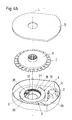
- FIGS. 4a to 4c shown from Figures 3a to 3c, wherein the only difference is that the two are on the steering axis L coaxially arranged gears 1, 2 each with an internal toothing 12 or 22 are provided and that the toothing 31 of the drive gear 3 accordingly with the internal gears 12, 22 combs.
- the drive gear 3 is within the Ring arranged by the base body 10, 20 of the two coaxially arranged gears 1, 2 is formed.
- Embodiments of the invention is additional for a rough determination of the complete steering angle (over the total number of turns of the steering wheel, that is in particular beyond 360 degrees) by means of the gear wheels 1, 2, 3 still a fine determination of the steering angle during one turn (i.e. between 0 ° and 360 °) by means of of the code C which can be scanned by a detection device E. possible.
- the gears 1, 2, 3 and the associated Sensor device 15 25 generated measurement results the steering angle can in addition to determining the Number of turns of the steering wheel (starting from one Reference position) also for a plausibility check of the determined by the detection device E steering angle serve.
Abstract
Description
Die Erfindung betrifft eine Vorrichtung zur Bestimmung des
Lenkwinkels eines Lenkrades nach dem Oberbegriff des Patentanspruchs
1.The invention relates to a device for determining the
Steering angle of a steering wheel according to the preamble of the
Eine derartige Vorrichtung umfasst einen Codeträger sowie eine Einrichtung zur Abtastung eines auf dem Codeträger vorgesehenen Codes, die bei einer Änderung des Lenkwinkels zueinander bewegt werden, wobei die Einrichtung zur Abtastung des Codes ein Ausgangssignal erzeugt, aus dem der Lenkwinkel ermittelbar ist.Such a device comprises a code carrier as well a device for scanning one on the code carrier provided codes when changing the steering angle are moved towards each other, the device for scanning of the code generates an output signal from which the Steering angle can be determined.
Derartige Systeme zur Bestimmung des Lenkwinkels eines Lenkrades, insbesondere in Kraftfahrzeugen, sind allgemein bekannt. Such systems for determining the steering angle of a Steering wheel, especially in motor vehicles, are general known.
Besondere Probleme können bei der Realisierung derartiger Systeme auftreten, wenn der Lenkwinkel nicht nur zwischen den Werten von 0° und 360° bestimmt werden soll, sondern wenn darüber hinaus auch noch die Anzahl vollständiger Umdrehungen des Lenkrades erkannt werden soll. Derartige Systeme zur Bestimmung des Lenkwinkels werden insbesondere benötigt, wenn die Hinterachse eines Fahrzeugs elektronisch direkt über den Lenkwinkelsensor gesteuert werden soll oder wenn mit der Beleuchtungseinrichtung eines Kraftfahrzeugs die Fahrbahn je nach Fahrtrichtung variabel ausgeleuchtet werden soll.Particular problems can arise when realizing such Systems occur when the steering angle is not just between the values of 0 ° and 360 ° should be determined, but if moreover the number is more complete Revolutions of the steering wheel should be recognized. such Systems for determining the steering angle are particularly popular needed when the rear axle of a vehicle is electronic should be controlled directly via the steering angle sensor or if with the lighting device of a motor vehicle the roadway is variably illuminated depending on the direction of travel shall be.
Hierbei besteht das Problem, dass der Umdrehungszähler auch dann aktiviert sein soll, wenn das Bordnetz des entsprechenden Kraftfahrzeugs abschaltet ist. Dies schließt eine rein elektronische Lösung aus, wenn nicht auf einen zusätzlichen Akkubetrieb zurückgegriffen werden soll.The problem here is that the revolution counter too should be activated when the vehicle electrical system of the corresponding Motor vehicle is switched off. This includes one electronic solution, if not an additional one Battery operation should be used.
Aus der DE 198 07 522 A1 ist es bekannt, zur Bestimmung des Lenkwinkels einen um die Lenkachse geführten Riemen zu verwenden, dessen Position mittels eines Sensors erfasst wird. Das System ist derart ausgelegt, dass der Riemen bei mehreren Umdrehungen des Lenkrades höchstens einmal umläuft.From DE 198 07 522 A1 it is known to determine the Steering angle to a belt guided around the steering axis use, whose position is detected by a sensor becomes. The system is designed so that the belt at rotates several turns of the steering wheel at most once.
Aus der EP 0 853 355 A2 ist eine einstufige Getriebelösung
mit einem auf der Lenkachse gelagerten Innenzahnrad und
einem zugeordneten Außenzahnrad bekannt, die mit einer
unterschiedlichen Anzahl an Zähnen versehen sind.
Der Erfindung liegt das Problem zugrunde, eine neue Vorrichtung zur Erfassung des Lenkwinkels eines Lenkrades zu schaffen, mit der die Anzahl der Umdrehungen des Lenkrades in einfacher Weise ermittelbar ist.The problem underlying the invention is a new device to detect the steering angle of a steering wheel create with the the number of turns of the steering wheel can be determined in a simple manner.
Erfindungsgemäß wird dieses Problem durch die Schaffung
einer Vorrichtung mit den Merkmalen des Patentanspruchs 1
gelöst.According to the invention, this problem is created by
a device with the features of
Danach wird der Codeträger durch eines von zwei auf einer gemeinsamen Achse axial hintereinander angeordneten Getriebeelementen gebildet, die mit einem durch das Lenkrad angetriebenen Antriebselement in Wirkverbindung stehen und die bei einer Änderung des Lenkwinkels zueinander verdreht werden.Then the code carrier is replaced by one of two on one common axis axially one behind the other gear elements formed with one by the steering wheel driven drive element are in operative connection and which rotates with each other when the steering angle changes become.
Die erfindungsgemäße Lösung beruht auf der Erkenntnis, aus der Getriebetechnik bekannte Anordnungen, bei denen zwei koaxial zueinander angeordnete Getriebeelemente mit einem gemeinsamen Antriebselement in Wirkverbindung stehen, zur Erzielung einer hohen Übersetzung in einer Vorrichtung zur Erfassung des Lenkwinkels eines Lenkrades zu nutzen. Hierdurch lässt sich anhand der Drehbewegung des entsprechenden Getriebeelementes nicht nur der jeweilige Lenkwinkel zwischen 0° und 360°, sondern insbesondere auch die Anzahl der Umdrehungen des Lenkrades ausgehend von einer definierten Nullpunktlage ermitteln. Insbesondere wird hier unter dem Lenkwinkel nicht einfach ein Winkel zwischen 0° und 360° verstanden, sondern der Lenkwinkel wird als ein absoluter Lenkwinkel angesehen, der ausgehend von einer Referenzlage bei einer Drehung des Lenkrades fortlaufend erhöht wird, etwa bei zehn möglichen Umdrehungen eines Lenkrades zwischen 0° und 360°. The solution according to the invention is based on the knowledge of arrangements known in transmission technology, in which two Gear elements arranged coaxially with one another common drive element are operatively connected to Achieving a high translation in a device for Detect the steering angle of a steering wheel. hereby can be determined by the rotation of the corresponding Gear element not only the respective steering angle between 0 ° and 360 °, but especially the number of Turns of the steering wheel based on a defined Determine the zero point position. In particular, here under the Steering angle is not simply an angle between 0 ° and 360 ° understood, but the steering angle is considered an absolute Steering angle viewed from a reference position is continuously increased when the steering wheel is turned, about at ten possible turns of a steering wheel between 0 ° and 360 °.
Die erfindungsgemäße Vorrichtung dient nicht in erster Linie zur genauen Bestimmung des Lenkwinkels zwischen 0° und 360°, sondern vielmehr zur Bestimmung der Anzahl der Umdrehungen des Lenkrades ausgehend von der Nullpunktlage. Es geht hier also insbesondere darum, bei der Bestimmung des absoluten Lenkwinkels - von der Nullpunktlage des Lenkrades aus fortlaufend gemessen - Vielfache von 360° (also komplette Umdrehungen) korrekt zu erfassen. Für die präzise Bestimmung des jeweiligen Lenkwinkels innerhalb einer Umdrehung (also zwischen 0° und 360° beziehungsweise 360° und 720° etc.) kann gegebenenfalls ein zusätzlicher Lenkwinkelsensor verwendet werden.The device according to the invention is not used first Line for the exact determination of the steering angle between 0 ° and 360 °, but rather to determine the number of Turns of the steering wheel starting from the zero point position. So here it is particularly about determination the absolute steering angle - from the zero point position of the Steering wheel measured continuously - multiples of 360 ° (i.e. complete revolutions) correctly. For the precise determination of the respective steering angle within one revolution (i.e. between 0 ° and 360 ° respectively 360 ° and 720 ° etc.) may be an additional one Steering angle sensor can be used.
Unter einem Code und einer zugeordneten Einrichtung zur Abtastung des Codes werden vorliegend beliebige, zueinander bewegliche Baugruppen verstanden, die aufgrund einer Relativbewegung ein Ausgangssignal erzeugen, anhand dessen das Ausmaß der Drehbewegung des mit dem Code versehenen Getriebeelementes erfassbar ist. Zur Abtastung des Codes können insbesondere elektrische magnetische oder optische Messprinzipien zur Anwendung kommen. So kann die bei einer Drehung des entsprechenden Getriebeelementes auftretende Änderung eines elektrischen Widerstandes bestimmt werden, nämlich durch Verwendung eines Potentiometers, das den Code in Form eines elektrischen Widerstandes sowie die zugeordnete Abtasteinrichtung in Form eines Abgriffs bildet. Neben dieser besonders einfach zu verwirklichenden Abtastanordnung können beispielsweise ein auf dem Halleffekt basierendes magnetisches Messprinzip oder ein auf der Abtastung definierter Markierungen beruhendes optisches Messprinzip eingesetzt werden. Under a code and an associated facility for In the present case, the scanning of the code is arbitrary to one another Movable assemblies understood that due to a relative movement generate an output signal based on which the Extent of the rotational movement of the gear element provided with the code is detectable. You can scan the code in particular electrical magnetic or optical measuring principles come into use. So it can with a rotation of the corresponding gear element change of an electrical resistance can be determined, namely by using a potentiometer that shaped the code of an electrical resistance as well as the associated one Scanning device forms in the form of a tap. Next this particularly simple to implement scanning arrangement can, for example, be based on the Hall effect magnetic measuring principle or one on the scan optical measuring principle based on defined markings be used.
Die erfindungsgemäße Lösung hat den Vorteil, dass sie als einstufige Lösung kostengünstig und technisch einfach realisierbar ist. Darüber hinaus arbeitet die erfindungsgemäße Vorrichtung geräuscharm.The solution according to the invention has the advantage that it as one-step solution inexpensive and technically simple is feasible. In addition, the invention works Device quiet.
Als axial hintereinander angeordnete Getriebeelemente eignen sich insbesondere Zahnräder, die mit mindestens einer Gegenverzahnung des Antriebselementes in Eingriff stehen.As axially arranged gear elements are particularly suitable gears with at least a counter toothing of the drive element in engagement stand.
Die beiden Getriebeelemente sind derart angeordnet und ausgebildet, dass sie bei einer Änderung des Lenkwinkels um einen Winkel zueinander verdreht werden, der erheblich kleiner ist als der Lenkwinkel, vorzugsweise derart, dass die beiden Getriebeelemente bei der maximal möglichen Änderung des Lenkwinkels (entsprechend der maximal möglichen Anzahl an Umdrehungen des Lenkrades) um einen Winkel von weniger als 360° zueinander verdreht werden.The two gear elements are arranged and trained that when the steering angle changes be rotated at an angle to each other that is significant is smaller than the steering angle, preferably such that the two transmission elements at the maximum possible Change the steering angle (according to the maximum possible Number of turns of the steering wheel) by one angle less than 360 ° to each other.
Die beiden Getriebeelemente sind vorzugsweise koaxial auf der Lenkradachse gelagert.The two gear elements are preferably coaxial the steering wheel axle.
Weiterhin ist es vorteilhaft, dass eines der beiden Getriebeelemente drehfest und das andere drehbar auf der gemeinsamen Achse gelagert ist, wobei das drehbar gelagerte Getriebeelement als Codeträger dient, also mit dem abzutastenden Code versehen ist. .It is also advantageous that one of the two gear elements rotatable and the other rotatable on the common Axis is mounted, the rotatably mounted gear element serves as a code carrier, i.e. with the one to be scanned Code is provided. ,
Die erforderliche Übersetzung kann insbesondere dadurch erreicht werden, dass die beiden Getriebeelemente eine unterschiedliche Anzahl an Zähnen aufweisen, wobei eine möglichst geringe Differenz der Anzahl an Zähnen (beispielsweise ein Zahnrad mit 50 Zähnen und ein Zahnrad mit 49 Zähnen) vorteilhaft ist.The required translation can in particular thereby achieved that the two gear elements one have different numbers of teeth, one The smallest possible difference in the number of teeth (for example a gear with 50 teeth and a gear with 49 Teeth) is advantageous.
Bei dem Antriebselement, das bei einer Drehung des Lenkrades (entsprechend einer Änderung des Lenkwinkels) angetrieben wird und dabei auf die beiden Getriebeelemente einwirkt, kann es sich insbesondere um ein (um seine Mittelachse) drehbar gelagertes Zahnrad handeln, dessen Durchmesser kleiner ist als der Durchmesser der beiden Getriebeelemente und das bezüglich der Getriebeelemente ein Planetenrad bildet.With the drive element that occurs when the steering wheel rotates (corresponding to a change in the steering angle) driven and acts on the two gear elements, can in particular be a (about its central axis) act rotatable gear, its diameter is smaller than the diameter of the two gear elements and that with respect to the gear elements a planet gear forms.
Die Drehachse des Antriebselementes verläuft bei Anordnung der beiden axial hintereinander angeordneten Getriebeelemente auf der Lenkachse parallel zu dieser und das Antriebselement weist zwei axial hintereinander angeordnete Verzahnungsbereiche auf, von denen jeder mit einem der beiden Getriebeelemente in Eingriff steht.The axis of rotation of the drive element runs when arranged of the two axially arranged transmission elements on the steering axis parallel to this and the drive element has two toothed areas arranged axially one behind the other on, each with one of the two Gear elements is engaged.
Gemäß einer Ausführungsform weisen die beiden Verzahnungsbereiche des Antriebselementes die gleiche Form und Anzahl der Zähne auf. Es können jedoch auch unterschiedlich gestaltete Verzahnungsbereiche mit einer unterschiedlichen Anzahl an Zähnen vorgesehen sein.According to one embodiment, the two toothed areas have the drive element the same shape and number of teeth. However, it can also be designed differently Gear areas with a different number be provided on teeth.
Ferner können mehrere Antriebselemente vorgesehen sein, die entlang des Umfangs der beiden Getriebeelemente voneinander beabstandet angeordnet sind. Hierdurch kann eine verbesserte Zentrierung des Getriebes sowie ein verbesserter Toleranzausgleich bei gleichzeitiger Vermeidung von Unwuchten erreicht werden. Furthermore, several drive elements can be provided along the circumference of the two gear elements from each other are arranged at a distance. This can improve Centering of the gearbox and improved tolerance compensation while avoiding imbalance can be achieved.
Gemäß einer Variante der Erfindung weisen die beiden Getriebeelemente jeweils eine Außenverzahnung auf, in die das Antriebselement eingreift. Alternativ kann je eine Innenverzahnung an den beiden Getriebeelementen vorgesehen sein, in die das Antriebselement eingreift.According to a variant of the invention, the two gear elements have each have an external toothing in which the Engages drive element. Alternatively, an internal toothing can be used be provided on the two gear elements in which engages the drive element.
Ferner kann die Verzahnung mindestens eines der beiden Getriebeelemente entlang des Umfanges des Getriebeelementes eine Variation in der Ausbildung der Zähne aufweisen. Hierdurch kann eine Nichtlinearität in der Übersetzung erzielt werden. So besteht die Möglichkeit, am entsprechenden Getriebeelement Blindbereiche vorzusehen, bei deren Zusammenwirken mit dem Antriebselement keine Relativbewegung der beiden Getriebeelemente erfolgt, also durch die Abtasteinrichtung auch keine entsprechend veränderten Ausgangssignale (Sensorsignale) erzeugt werden. Damit kann der Verschleiß der Abtasteinrichtung insbesondere bei Geradeausfahrt minimiert werden. Im Grenzfall läßt sich bei dieser Ausführungsform eher ein Umschalten der beiden Getriebeelemente zueinander als ein kontinuierliches Verdrehen erreichen.Furthermore, the toothing can be at least one of the two Gear elements along the circumference of the gear element have a variation in the formation of the teeth. This can result in a non-linearity in the translation be achieved. So there is the possibility at the appropriate Gear element to provide blind areas at their Interaction with the drive element no relative movement of the two transmission elements, that is, by the Scanning device also no correspondingly changed Output signals (sensor signals) are generated. So that can the wear of the scanning device, especially when driving straight ahead be minimized. In the borderline case, this embodiment rather a switching of the two Gear elements to each other as a continuous twisting to reach.
In einer bevorzugten Weiterbildung der Erfindung ist das Antriebselement derart beweglich gelagert, dass hiermit Toleranzen hinsichtlich der Position der beiden auf einer gemeinsamen Achse angeordneten und mit dem Antriebselement in Eingriff befindlichen Getriebeelemente ausgeglichen werden können. Da diese Getriebeelemente vorzugsweise auf der Lenkachse einer Lenkradanordnung anzuordnen sind, wirken sich Toleranzen hinsichtlich der Anordnung und Ausbildung der Lenksäule der Lenkradanordnung unmittelbar auch auf die Position der besagten Getriebeelemente aus. Ty-Axialtoleranzen mit einer Größenordnung von zwei Millimeter sowie eine Verkippung (Schlag) von bis zu zwei Grad auf. Zum Ausgleich derartiger Toleranzen in der Position der Getriebeelemente ist das zugeordnete Antriebselement in radialer und/oder axialer Richtung beweglich. Dabei ist das Antriebselement vorzugsweise elastisch in Richtung auf eine Vorzugsposition vorgespannt, in der es mit den Getriebeelementen in Eingriff steht, und kann zum Ausgleich von Toleranzen derart bewegt werden, dass der Eingriff in die Getriebeelemente aufrecht erhalten wird. Das heißt, das mittels mindestens eines elastischen Elementes federnd gelagerte Antriebselement kann sich an toleranzbedingte Abweichungen in der Position der zugehörigen Getriebeelemente axial bzw. radial anpassen.In a preferred development of the invention, this is Drive element movably mounted so that hereby Tolerances regarding the position of the two on one arranged common axis and with the drive element engaged gear elements balanced can be. Because these gear elements preferably on the steering axis of a steering wheel arrangement are to be arranged, tolerances regarding the arrangement and Training of the steering column of the steering wheel assembly immediately also on the position of said gear elements. Ty-axial tolerances on the order of two millimeters as well as a tilt (impact) of up to two degrees. To compensate for such tolerances in the position of Gear elements is the assigned drive element in radial and / or axial direction movable. It is Drive element preferably elastically towards one Preloaded position in which it is with the gear elements is engaged, and can compensate for tolerances be moved such that the engagement in the Gear elements is maintained. That is, by means of at least one elastic element resiliently mounted Drive element can adapt to tolerance-related deviations in the position of the associated gear elements axially or adjust radially.
Neben der einfachen Möglichkeit eines Toleranzausgleichs zeichnet sich die erfindungsgemäße Lösung auch dadurch aus, dass - im Gegensatz zu üblichen Planetengetrieben - die Krafteinleitung in das als Lenkwinkelmesssystem dienende Getriebe über das Planetenrad als Antriebselement erfolgt. Denn dieses wird bei Drehung des Lenkrades auf einer Kreisbahn bewegt, deren Mittelpunkt durch die Mittelachse der beiden mit dem Antriebselement zusammenwirkenden Getriebeelemente gebildet wird, wobei das Antriebselement, sich um die eigene Achse drehend, auf den Getriebeelementen abrollt. Hierdurch sowie insbesondere durch das Zusammenfallen der Lenkachse mit der Mittelachse der Getriebeelemente wird ein besonders einfacher, kompakter Aufbau des Getriebes mit nur wenigen Getriebeelementen ermöglicht.In addition to the easy option of tolerance compensation the solution according to the invention is also characterized by that - in contrast to conventional planetary gears - the Force transmission into the one serving as the steering angle measuring system Transmission takes place via the planet gear as a drive element. Because this turns when the steering wheel turns on a circular path moves whose center through the central axis of the two gear elements interacting with the drive element is formed, the drive element, around rotating its own axis, rolling on the gear elements. As a result, and in particular by collapsing the steering axis with the central axis of the gear elements becomes a particularly simple, compact construction of the transmission made possible with just a few gear elements.
Weitere Merkmale und Vorteile der Erfindung werden bei der nachfolgende Beschreibung eines Ausführungsbeispiels anhand der Figuren deutlich werden. Other features and advantages of the invention are in the following description of an embodiment with reference to of the figures become clear.
Es zeigen:
- Fig. 1
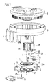
- Eine Explosionsdarstellung einer Vorrichtung zur Bestimmung des Lenkwinkels eines Lenkrades mit zwei koaxial hintereinander angeordneten Zahnrädern mit Außenverzahnung und einem mit beiden Zahnrädern in Eingriff stehenden Antriebsritzel, das bei Änderung des Lenkwinkels mitgenommen wird;
- Fig. 2a
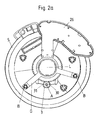
- eine Unteransicht der Vorrichtung aus
Figur 1 im montierten Zustand; - Fig. 2b
- eine perspektivische Ansicht der Vorrichtung aus
Figur 1 im montierten Zustand; - Fig. 2c
- eine Seitenansicht der Vorrichtung aus
Figur 1 im montierten Zustand; - Fig. 3a
- eine Explosionsdarstellung einer ersten Abwandlung
des Ausführungsbeispiels aus
den Figuren 1 bis 2c; - Fig. 3b
- die Vorrichtung aus Figur 3a im teilweise zusammengebauten Zustand;
- Fig. 3c
- eine Seitenansicht der Vorrichtung aus den Figuren 3a und 3b;
- Fig. 4a
- eine Explosionsdarstellung einer zweiten Abwandlung
der Vorrichtung aus
den Figuren 1 bis 2c, wobei die beiden koaxial gelagerten Zahnräder jeweils eine Innenverzahnung aufweisen; - Fig. 4b
- die Vorrichtung aus Figur 4a im teilweise zusammengebauten Zustand;
- Fig. 4c
- eine Seitenansicht der Vorrichtung aus den Figuren 4a und 4b.
- Fig. 1
- An exploded view of a device for determining the steering angle of a steering wheel with two coaxially arranged gears arranged one behind the other with external teeth and a gear meshing with both gears, which is taken when the steering angle changes;
- Fig. 2a
- a bottom view of the device of Figure 1 in the assembled state;
- Fig. 2b
- a perspective view of the device of Figure 1 in the assembled state;
- Fig. 2c
- a side view of the device of Figure 1 in the assembled state;
- Fig. 3a
- an exploded view of a first modification of the embodiment of Figures 1 to 2c;
- Fig. 3b
- the device of Figure 3a in the partially assembled state;
- Fig. 3c
- a side view of the device of Figures 3a and 3b;
- Fig. 4a
- an exploded view of a second modification of the device of Figures 1 to 2c, wherein the two coaxially mounted gears each have an internal toothing;
- Fig. 4b
- the device of Figure 4a in the partially assembled state;
- Fig. 4c
- a side view of the device of Figures 4a and 4b.
In den Figuren 1 bis 2c ist in verschiedenen Ansichten eine Lenkwinkelsensoreinrichtung für ein Kraftfahrzeug mit einem Rotor R und einem Stator S dargestellt. Der Rotor R ist derart mit dem Lenkrad verbunden, zum Beispiel über eine Lenkspindel, dass er bei einer Drehung des Lenkrades um die Lenkachse L gedreht wird. Der Stator S ist demgegenüber mittels geeigneter Befestigungselemente an einer nicht gemeinsam mit dem Lenkrad bewegbaren, ortsfesten Baugruppe des Kraftfahrzeugs befestigt. Die in Figur 1 dargestellte Rotor-Stator-Anordnung ist derart ausgelegt, dass sie zur Übertragung elektrischer Signale zwischen Rotor R und Stator S mittels elektrischer Leitungen geeignet ist, die sich vom Rotor zum Stator erstrecken und die bei einer Drehbewegung auf- beziehungsweise abgewickelt werden. Eine derartige Rotor-Stator-Anordnung ist beispielsweise aus der DE 200 07 862 U1 bekannt. Hierauf wird hinsichtlich weiterer Einzelheiten der Rotor-Stator-Anordnung und insbesondere deren Kopplung mit einer Lenkeinrichtung voll inhaltlich Bezug genommen.In Figures 1 to 2c is one in different views Steering angle sensor device for a motor vehicle with a Rotor R and a stator S shown. The rotor R is connected to the steering wheel in this way, for example via a Steering spindle that it turns when the steering wheel around the Steering axis L is rotated. The stator S is in contrast by means of suitable fastening elements on one Fixed assembly that can be moved together with the steering wheel attached to the motor vehicle. The one shown in Figure 1 Rotor-stator arrangement is designed such that it is used for Transmission of electrical signals between rotor R and Stator S is suitable by means of electrical lines extend from the rotor to the stator and which at one Rotary movement are wound up or unwound. A such rotor-stator arrangement is for example from the DE 200 07 862 U1 known. This is followed for further Details of the rotor-stator arrangement and in particular their coupling with a steering device in full content Referred.
Die Besonderheit der in den Figuren 1 bis 2c dargestellten Anordnung liegt in der Vorrichtung zur Erfassung des Lenkwinkels, d.h., desjenigen Winkels, um den der Rotor bei einer Drehung des Lenkrades verdreht wird. Es geht dabei nicht in erster Linie um die Bestimmung des Lenkwinkels innerhalb einer Umdrehung des Lenkrades, d.h., in einem Winkelbereich zwischen 0° und 360°, sondern vielmehr insbesondere um die Bestimmung der Anzahl an Umdrehungen des Lenkrades ausgehend von einer definierten Referenzlage des Lenkrades.The peculiarity of those shown in Figures 1 to 2c Arrangement lies in the device for detecting the steering angle, i.e. the angle through which the rotor at a rotation of the steering wheel is rotated. It works not primarily to determine the steering angle within one revolution of the steering wheel, i.e. in one Angular range between 0 ° and 360 °, but rather in particular to determine the number of revolutions of the Steering wheel based on a defined reference position of the Steering wheel.
Die hierfür vorgesehene Vorrichtung umfasst zwei koaxial
auf der Lenkachse L hintereinander angeordnete Zahnräder 1,
2 mit einem ringförmigen Grundkörper 10, 20 und je einer
Außenverzahnung 11, 12. Das eine Zahnrad 1 ist frei drehbar
auf der Lenkachse L gelagert und das andere Zahnrad 2 ist
über ein Gestell G und Befestigungsmittel B drehfest am
Stator S festgelegt.The device provided for this purpose comprises two
Den beiden zueinander verdrehbaren Zahnrädern 1,2 ist ein
Planetenzahnrad 3 zugeordnet, das mittels eines Lagerbolzens
35 und eines Lagerstückes 36, welches mittels eines Befestigungsabschnittes
37 radial verschieblich bezüglich der
Lenkachse L in einer T-Nut 38 am äußeren Rand der Aufnahmehülse
H aufgenommen ist, drehbar am äußeren Rand einer Aufnahmehülse
H gelagert ist, die fest mit dem Rotor R verbunden
ist, also sich gemeinsam mit diesem dreht. Dies bedeutet,
dass bei einer Drehung des Rotors R (ausgelöst durch
eine Drehung des zugeordneten Lenkrades) die Hülse H gemeinsam
mit dem Rotor R um die Lenkachse L verschwenkt wird und
dass hierbei das Planetenzahnrad 3 durch die Hülse H mitgenommen
wird.The two
Die auf dem Grundkörper 30 des Planetenzahnrades 3 vorgesehene
Verzahnung 31 ist derart ausgebildet, daß sie sowohl
mit der Außenverzahnung 11 des frei drehbar gelagerten
ersten Zahnrades 1 als auch mit der Außenverzahnung 21 des
zweiten, drehfest gelagerten Zahnrades 2 kämmt. Dies bedeutet,
dass bei einer Drehung des Lenkrades und somit des
Rotors R zusammen mit der Aufnahmehülse H das Planetenzahnrad
3 mit seiner Verzahnung 31 auf den Außenverzahnungen
11, 21 der beiden Zahnräder 1, 2 abrollt. Da das Planetenzahnrad
3 mittels des Lagerbolzens 35 und des Lagerstückes
36, das mittels seines Befestigungsabschnittes 37 längsverschieblich
in einer T-Nut 38 am äußeren Rand der Aufnahmehülse
H aufgenommen ist, um eine parallel zur Lenkachse L
verlaufende Achse A drehbar gelagert ist, dreht sich das
Planetenzahnrad 3 hierbei um seine Achse A.The one provided on the
Aufgrund der längsverschieblichen Anordnung des Lagerstükkes
36 und damit auch des hierauf gelagerten Planetenzahnrades
3 lassen sich Toleranzen in der Position der auf der
Längsachse L angeordneten Zahnräder 1, 2 in radialer Richtung
ausgleichen. Derartige Toleranzen sind darauf zurückzuführen,
dass die die Längsachse L definierende Lenksäule
einer Lenkeinrichtung typischerweise Radialtoleranzen in
einer Größenordnung von etwa zwei Millimeter aufweist.
Diese können vorliegend in einfacher Weise durch radiales
Verschieben des Befestigungsabschnittes 37 des Lagerstückes
36 in der zugeordneten T-Nut 38 ausgeglichen werden. Das
Lagerstück 36 ist dabei durch elastische Mittel 39 in Form
von Federstahlelementen bezüglich der T-Nut 38 der Aufnahmehülse
H radial in Richtung auf die Zahnräder 1, 2 vorgespannt
und liegt kontinuierlich an diesen an. Zum Ausgleich
von Toleranzen lässt sich das Lagerstück 36 unter der
Wirkung dieser Vorspannung radial bezüglich der Lenkachse L
in jeweils die Position bringen, in der der Eingriff mit
den Zahnrädern 1, 2 gewährleistet ist.Due to the longitudinally displaceable arrangement of the
Durch Verschieben des Lagerstückes 36 zusammen mit dem
Planetenzahnrad 3 auf dem als Schraube ausgebildeten Lagerbolzen
35, der axial an einem Ende durch den Schraubenkopf
und am anderen Ende durch eine Mutter 35a begrenzt ist,
lassen sich zudem auch axiale Toleranzen hinsichtlich der
Anordnung der Zahnräder 1, 2 ausgleichen. Schließlich
ermöglicht eine kombinierte Bewegung des Lagerstückes 36 in
axialer Richtung (entlang der Lenkachse L) sowie radial
(senkrecht zur Lenkachse L) einen Ausgleich von Verkippungen
der Lenksäulen (Schlag), die typischerweise bis zu
zwei Grad betragen.By moving the
Neben dem vorstehend erläuterten, einfachen Toleranzausgleich
zeichnet sich das in den Figuren 1 bis 2c dargestellte
Getriebe durch seinen einfachen Aufbau mit einer geringen
Zahl an Getriebeelementen (insgesamt drei Getriebeelemente
1, 2, 3) aus. Dies wird vor allem dadurch erreicht,
dass die beiden Zahnräder 1, 2 auf der Lenkachse L angeordnet
sind und dass die Krafteinleitung in das Getriebe über
das Planetenzahnrad 3 erfolgt.In addition to the simple tolerance compensation explained above
is the one shown in Figures 1 to 2c
Gearbox due to its simple construction with a low
Number of gear elements (a total of three
Die Verzahnung 31 des Antriebszahnrades 3 wird sozusagen
gebildet durch zwei axial hintereinander angeordnete,
identische (und daher in den Figuren nicht separat eingezeichneten)
Verzahnungsbereiche, von denen der eine mit dem
ersten Zahnrad 1 und der zweite mit dem zweiten Zahnrad 2
in Eingriff steht. Gegebenenfalls können die beiden Verzahnungsbereiche
auch eine unterschiedliche Verzahnung aufweisen.The
Die Außenverzahnungen 11, 21 der beiden auf der Lenkachse L
gelagerten Zahnräder 1, 2 weisen vorzugsweise das gleiche
oder ein ähnliches Zahnmodul auf wie die Verzahnung 31 des
Planetenzahnrades 3.The external gears 11, 21 of the two on the steering axis L
Mounted gears 1, 2 preferably have the same
or a similar tooth module as the
Die beiden Zahnräder 1, 2 weisen jedoch eine geringfügig unterschiedliche
Zähnezahl auf, z. B. 49 Zähne einerseits und
50 Zähne andererseits, was zur Folge hat, dass es bei einem
Umlauf des Planetenzahnrades 3 zu einer geringfügigen
Verdrehung der beiden Zahnräder 1, 2 zueinander kommt, d.
h., das frei drehbar gelagerte erste Zahnrad 1 wird geringfügig
bezüglich des drehfest angeordneten zweiten Zahnrades
2 verdreht.The two
Der Versatz der beiden Zahnräder 1, 2 nach einer Umdrehung
des Zahnrades kann mittels einer hierfür vorgesehenen
Sensoreinrichtung 15, 25 erfaßt werden; und entsprechendes
gilt für den zunehmenden Versatz bei jeder weiteren Drehung
des Lenkrades und somit des Rotors R, bei der das Planetenzahnrad
3 mitgenommen wird und auf den Außenverzahnungen
11, 21 der beiden auf der Lenkachse L gelagerten Zahnräder
1, 2 abrollt. Bei einer hinreichend geringen Differenz in
der Anzahl der Zähne der beiden Außenverzahnungen 11, 21
und einer entsprechend großen Übersetzung kann erreicht
werden, dass bei der maximal möglichen Anzahl an Drehungen
des Lenkrades (z. B. zehn Umdrehungen) der Versatz der
beiden Zahnräder 1, 2 zueinander (also die relative Verdrehung
des frei drehbar gelagerten ersten Zahnrades 1 bezüglich
des drehfest angeordneten Zahnrades 2) maximal 360°
oder weniger beträgt. In diesem Fall läßt sich aus jeder
Stellung der beiden Zahnräder 1, 2 zueinander unmittelbar
die Anzahl der Umdrehungen des Rotors R und damit des
Lenkrades ablesen.The offset of the two
Die Auflösung innerhalb einer Umdrehung (entsprechend einem Lenkwinkel zwischen 0° und 360°) ist hierdurch geringer, so dass für eine genaue Bestimmung des Lenkwinkels innerhalb einer Umdrehung gegebenenfalls ein zusätzlicher Sensor eingesetzt werden muss. Die zur Bestimmung der Anzahl an Umdrehungen vorgesehene Vorrichtung kann dann zusätzlich zur Überwachung dieses weiteren Sensors anhand von Plausibilitätskontrollen eingesetzt werden. The resolution within one revolution (corresponding to one Steering angle between 0 ° and 360 °) is therefore smaller, so that for an accurate determination of the steering angle within an additional sensor if necessary must be used. The to determine the number of Revolutions provided device can then additionally to monitor this additional sensor using plausibility checks be used.
Die Sensoreinrichtung 15, 25 wird vorliegend durch einen
Magneten 15 gebildet, der sich ringartig entlang eines
Teiles des Umfanges des ersten Zahnrades 1 erstreckt.
Dieser Magnet 15 erzeugt einen magnetischen Code, der durch
ein zugeordnetes magnetfeldempfindliches und auf einer
Platine 26 gelagertes Sensorelement 25 abtastbar ist. Die
Platine 26 ist an einem Fortsatz F des Stators S befestigt,
so dass das magnetfeldempfindliche Sensorelement 25 ortsfest
gelagert ist. Das Magnetfeld am Ort des Sensorelementes
25 hängt somit von der Relativposition des den Magneten
15 tragenden ersten Zahnrades 1 bezüglich des zweiten Zahnrades
2 ab. Hierdurch läßt sich die Relativposition der
beiden Zahnräder 1, 2 und somit - wie oben erläutert - der
absolute Drehwinkel (unter Einschluß der Anzahl an Umdrehungen
des Lenkrades und somit des Rotors R) bestimmen.The
Anstelle von zwei auf der Lenkachse L gelagerten Zahnrädern können hierfür bei Bedarf auch mehr Zahnräder verwendet werden.Instead of two gear wheels mounted on the steering axle L. can use more gears if necessary become.
Das in den Figuren 3a bis 3c dargestellte Ausführungsbeispiel der Erfindung unterscheidet sich von dem anhand der Figuren 1 bis 2c Beschriebenen im wesentlichen dadurch, dass die Rotor-Stator-Anordnung nicht zur Übertragung elektrischer Signale zwischen Rotor und Stator ausgebildet ist. Der Stator wird in diesem Fall durch ein einfaches Gehäuse, bestehend aus einem Unterteil U und einem Deckel D gebildet, in dem der Rotor R drehbar gelagert ist.The embodiment shown in Figures 3a to 3c the invention differs from that based on the Figures 1 to 2c described essentially by that the rotor-stator arrangement is not used to transmit electrical Signals between the rotor and stator is formed. In this case, the stator is made by a simple housing, consisting of a lower part U and a cover D, in which the rotor R is rotatably mounted.
Ein weiterer Unterschied besteht darin, dass der Rotor R an seinem Umfang mit einer mittels einer Erfassungseinrichtung E optisch abtastbaren Codierung C versehen ist. Diese dient zur genaueren Bestimmung des Lenkwinkels innerhalb einer Umdrehung des Lenkrades. Die hierbei verwendete Erfassungseinrichtung E kann in üblicher Weise einen Sender sowie einen zugeordneten Empfänger umfassen, mit dem die Codierung C, zum Beispiel im Durchlichtverfahren, abgetastet wird.Another difference is that the rotor R on its scope with a means of a detection device E optically scannable coding C is provided. This serves for more precise determination of the steering angle within a Turn of the steering wheel. The detection device used here E can be a transmitter in the usual way as well comprise an assigned receiver with which the coding C, for example, in the transmitted light method becomes.
Im Übrigen stimmt das anhand der Figuren 3a bis 3c dargestellte Ausführungsbeispiel mit dem anhand der Figuren 1 bis 2c erläuterten überein, so dass diesbezüglich auf die Ausführungen zu den Figuren 1 bis 2c verwiesen wird.For the rest, this is correct with reference to FIGS. 3a to 3c Exemplary embodiment with the aid of FIGS. 1 to 2c explained so that in this regard to the Reference is made to Figures 1 to 2c.
In den Figuren 4a bis 4c ist eine Abwandlung des Ausführungsbeispiels
aus den Figuren 3a bis 3c dargestellt, wobei
der einzige Unterschied darin besteht, dass die beiden auf
der Lenkachse L koaxial hintereinander angeordneten Zahnräder
1, 2 jeweils mit einer Innenverzahnung 12 bzw. 22
versehen sind und dass die Verzahnung 31 des Antriebszahnrades
3 dementsprechend mit den Innenverzahnungen 12, 22
kämmt. Das Antriebszahnrad 3 ist hierzu innerhalb des
Ringes angeordnet, der durch die Grundkörper 10, 20 der
beiden koaxial angeordneten Zahnräder 1, 2 gebildet wird.A modification of the exemplary embodiment is shown in FIGS. 4a to 4c
shown from Figures 3a to 3c, wherein
the only difference is that the two are on
the steering axis L coaxially arranged
Bei dem anhand der Figuren 3a bis 3c und 4a bis 4c dargestellten
Ausführungsbeispielen der Erfindung ist zusätzlich
zu einer groben Bestimmung des vollständigen Lenkwinkels
(über die gesamte Anzahl an Umdrehungen des Lenkrades, also
insbesondere über 360 Grad hinaus) mittels der Zahnräder 1,
2, 3 noch eine feine Bestimmung des Lenkwinkels während
einer Umdrehung (d.h. jeweils zwischen 0° und 360°) mittels
des durch eine Erfassungseinrichtung E abtastbaren Codes C
möglich. Die mittels der Zahnräder 1, 2, 3 und der zugeordneten
Sensoreinrichtung 15, 25 generierten Messergebnissen
des Lenkwinkels können dabei neben der Bestimmung der
Anzahl an Umdrehungen des Lenkrades (ausgehend von einer
Referenzlage) auch für eine Plausibilitätsprüfung des
mittels der Erfassungseinrichtung E bestimmten Lenkwinkels
dienen.In the case of that illustrated with reference to FIGS. 3a to 3c and 4a to 4c
Embodiments of the invention is additional
for a rough determination of the complete steering angle
(over the total number of turns of the steering wheel, that is
in particular beyond 360 degrees) by means of the
Claims (24)
dadurch gekennzeichnet, dass der Codeträger durch eines von zwei auf einer gemeinsamen Achse (L) hintereinander angeordneten Getriebeelementen (1, 2) gebildet werden, die mit einem durch das Lenkrad angetriebenen Antriebselement (3) in Wirkverbindung stehen und die bei einer Änderung des Lenkwinkels zueinander verdreht werden.Device for determining the steering angle of a steering wheel, with a code carrier and with a device for scanning a code provided on the code carrier, which are rotated when the steering angle changes, the device for scanning the code generating an output signal from which the steering angle can be determined is
characterized in that the code carrier is formed by one of two gear elements (1, 2) arranged one behind the other on a common axis (L) , which are operatively connected to a drive element (3) driven by the steering wheel and which mutually change when the steering angle changes be twisted.
dadurch gekennzeichnet, dass die beiden Getriebeelemente (1, 2) bei einer Änderung des Lenkwinkels um einen Winkel zueinander verdreht werden, der kleiner als die Änderung des Lenkwinkels ist.Device according to one of the preceding claims,
characterized in that , when the steering angle changes , the two gear elements (1, 2) are rotated relative to one another by an angle which is smaller than the change in the steering angle.
dadurch gekennzeichnet, dass die beiden Getriebeelemente (1, 2) bei der maximal üblichen Änderung des Lenkwinkels um einen Winkel von weniger als 360° zueinander verdreht werden.Device according to one of the preceding claims,
characterized in that the two gear elements (1, 2) are rotated by an angle of less than 360 ° to one another when the steering angle is changed at most.
dadurch gekennzeichnet, dass die beiden Getriebeelemente (1, 2) auf der Lenkachse (L) gelagert sind.Device according to one of the preceding claims,
characterized in that the two gear elements (1, 2) are mounted on the steering axle (L).
dadurch gekennzeichnet, dass eines der beiden Getriebeelemente (1, 2) drehfest und das andere drehbar auf der gemeinsamen Achse gelagert ist und dass das drehbar gelagerte Getriebeelement (1) als Codeträger dient.Device according to one of the preceding claims,
characterized in that one of the two gear elements (1, 2) is rotatably and the other rotatably mounted on the common axis and that the rotatably mounted gear element (1) serves as a code carrier.
dadurch gekennzeichnet, dass das Antriebselement (3) drehbar gelagert ist.Device according to one of the preceding claims,
characterized in that the drive element (3) is rotatably mounted.
dadurch gekennzeichnet, dass das Antriebselement (3) als Zahnrad ausgebildet ist.Device according to one of the preceding claims,
characterized in that the drive element (3) is designed as a gear.
dadurch gekennzeichnet, dass das Antriebselement (3) auf einer Achse (A) drehbar gelagert ist, die parallel zur Lenkradachse (L) verläuft.Device according to one of the preceding claims,
characterized in that the drive element (3) is rotatably mounted on an axis (A) which runs parallel to the steering wheel axis (L).
dadurch gekennzeichnet, dass das Antriebselement (3) zwei axial hintereinander angeordnete Verzahnungsbereiche aufweist, von denen jeder mit einem der beiden Getriebeelemente (1, 2) in Eingriff steht.Device according to one of the preceding claims,
characterized in that the drive element (3) has two toothed areas arranged axially one behind the other, each of which meshes with one of the two gear elements (1, 2).
dadurch gekennzeichnet, dass mehrere Antriebselemente (3) vorgesehen sind, die entlang des Umfangs der beiden Getriebeelemente (1, 2) voneinander beabstandet angeordnet sind.Device according to one of the preceding claims,
characterized in that a plurality of drive elements (3) are provided which are arranged spaced apart from one another along the circumference of the two gear elements (1, 2).
dadurch gekennzeichnet, dass die beiden Getriebeelemente (1, 2) jeweils eine Außenverzahnung (11, 21) aufweisen.Device according to one of the preceding claims,
characterized in that the two gear elements (1, 2) each have external teeth (11, 21).
dadurch gekennzeichnet, dass der Code mittels der Abtasteinrichtung (25) nach einem elektrischen, magnetischen oder optischen Prinzip abgetastet wird. Device according to one of the preceding claims,
characterized in that the code is scanned by the scanning device (25) according to an electrical, magnetic or optical principle.
dadurch gekennzeichnet, dass das Antriebselement (3) in radialer Richtung und/oder axialer Richtung bezüglich der gemeinsamen Achse (L) der Getriebeelemente (1, 2) verschieblich gelagert ist.Device according to one of the preceding claims,
characterized in that the drive element (3) is mounted displaceably in the radial direction and / or axial direction with respect to the common axis (L) of the gear elements (1, 2).
dadurch gekennzeichnet, dass die Antriebskraft in das durch die Getriebeelemente (1, 2) und das Antriebselement (3) gebildete Getriebe durch das Antriebselement (3) eingeleitet wird.Device according to one of the preceding claims,
characterized in that the driving force is introduced into the transmission formed by the transmission elements (1, 2) and the drive element (3) through the drive element (3).
dadurch gekennzeichnet, dass zusätzlich eine Erfassungseinrichtung (E) mit einem zugeordneten Code (C) zur Bestimmung des Lenkwinkels innerhalb einer Umdrehung des Lenkrades vorgesehen ist.Device according to one of the preceding claims,
characterized in that additionally a detection device (E) with an assigned code (C) is provided for determining the steering angle within one revolution of the steering wheel.
Applications Claiming Priority (2)
| Application Number | Priority Date | Filing Date | Title |
|---|---|---|---|
| DE10158287A DE10158287B4 (en) | 2001-11-20 | 2001-11-20 | Device for determining the steering angle of a steering wheel |
| DE10158287 | 2001-11-20 |
Publications (3)
| Publication Number | Publication Date |
|---|---|
| EP1312534A2 true EP1312534A2 (en) | 2003-05-21 |
| EP1312534A3 EP1312534A3 (en) | 2004-03-24 |
| EP1312534B1 EP1312534B1 (en) | 2006-07-19 |
Family
ID=7707208
Family Applications (1)
| Application Number | Title | Priority Date | Filing Date |
|---|---|---|---|
| EP02090375A Expired - Fee Related EP1312534B1 (en) | 2001-11-20 | 2002-11-11 | Steering wheel steering angle determination apparatus |
Country Status (5)
| Country | Link |
|---|---|
| US (1) | US20030094054A1 (en) |
| EP (1) | EP1312534B1 (en) |
| JP (1) | JP2003214845A (en) |
| DE (2) | DE10158287B4 (en) |
| ES (1) | ES2267938T3 (en) |
Cited By (2)
| Publication number | Priority date | Publication date | Assignee | Title |
|---|---|---|---|---|
| CN101190689B (en) * | 2006-12-01 | 2010-09-08 | 现代摩比斯株式会社 | Steering angle sensor assembly for vehicle |
| CN109398484A (en) * | 2017-08-18 | 2019-03-01 | 凯尔西-海耶斯公司 | Absolute steering angle sensor module |
Families Citing this family (7)
| Publication number | Priority date | Publication date | Assignee | Title |
|---|---|---|---|---|
| DE10339963B4 (en) * | 2003-08-26 | 2007-07-26 | Børsting, John | encoders |
| DE102009011352B3 (en) * | 2009-03-05 | 2010-07-15 | Bourns, Inc., Riverside | Torsion angle sensor for measuring torsion angle of two shafts coupled with each other, has torsion bar, by which two shafts are connected with each other, housing and rotational position sensor |
| WO2011013217A1 (en) | 2009-07-29 | 2011-02-03 | トヨタ自動車株式会社 | Steering control system |
| DE112010005795B4 (en) * | 2010-08-05 | 2017-02-23 | Toyota Jidosha Kabushiki Kaisha | Steering control device |
| DE102012109787B4 (en) * | 2012-10-15 | 2014-05-15 | Takata AG | Steering angle sensor for motor vehicles |
| DE102014102982B3 (en) | 2014-03-06 | 2015-03-05 | Horst Scholz Gmbh & Co. Kg | Steering angle sensor |
| CN109238079B (en) * | 2018-11-05 | 2020-09-25 | 兰州万里航空机电有限责任公司 | Adjustable deflection instrument |
Citations (2)
| Publication number | Priority date | Publication date | Assignee | Title |
|---|---|---|---|---|
| EP0853355A2 (en) | 1997-01-14 | 1998-07-15 | Lucas Industries Public Limited Company | Electrical connector |
| DE19807522A1 (en) | 1998-02-21 | 1999-03-25 | Bosch Gmbh Robert | Rotation angle and rpm sensor, e.g. for steering column of motor vehicle |
Family Cites Families (21)
| Publication number | Priority date | Publication date | Assignee | Title |
|---|---|---|---|---|
| JPH0391908U (en) * | 1989-12-29 | 1991-09-19 | ||
| JPH04325375A (en) * | 1991-04-25 | 1992-11-13 | Honda Motor Co Ltd | Steering angle sensor for vehicle |
| DE4115244C2 (en) * | 1991-05-10 | 1998-07-16 | Bayerische Motoren Werke Ag | Angle sensor for determining the rotational position of a steering shaft of a motor vehicle |
| US5243188A (en) * | 1991-09-26 | 1993-09-07 | Kabushiki Kaisha Tokai Rika Denki Seisakusho | Neutral position detector for steering wheels having a first and second rotors with aligned slots |
| GB9202868D0 (en) * | 1992-02-12 | 1992-03-25 | Lucas Ind Plc | Optical torque sensors and steering systems for vehicles incorporating them |
| DE4409892A1 (en) * | 1994-03-23 | 1995-09-28 | Bosch Gmbh Robert | Steering angle sensor |
| DE19506938A1 (en) * | 1995-02-28 | 1996-08-29 | Bosch Gmbh Robert | Method and device for measuring the angle of a rotatable body |
| ES2150059T3 (en) * | 1995-11-17 | 2000-11-16 | Kostal Leopold Gmbh & Co Kg | ANGLE DETECTOR. |
| DE19601965A1 (en) * | 1996-01-20 | 1997-07-24 | Teves Gmbh Alfred | Steering angle sensor with revolution counter |
| US6759648B2 (en) * | 1997-08-15 | 2004-07-06 | Bishop Innovation Limited | Sensor for sensing absolute angular position of a rotatable body |
| DE19739823A1 (en) * | 1997-09-11 | 1999-03-18 | Bosch Gmbh Robert | Method and device for measuring the angle of a first rotatable body |
| US6155106A (en) * | 1997-10-29 | 2000-12-05 | Alps Electric Co., Inc. | Steering angle sensor unit |
| JP3612205B2 (en) * | 1998-02-26 | 2005-01-19 | アルプス電気株式会社 | COUPLING TOOL AND ROTATION ANGLE SENSOR USING THIS COUPLING TOOL |
| US6248993B1 (en) * | 1998-08-05 | 2001-06-19 | Leopold Kostal Gmbh & Co. Kg | Steering angle sensor |
| JP2000205811A (en) * | 1999-01-08 | 2000-07-28 | Alps Electric Co Ltd | Rotary sensor |
| DE19902739C2 (en) * | 1999-01-25 | 2001-10-25 | Wolfgang Schleicher | Encoder |
| JP3821978B2 (en) * | 1999-02-22 | 2006-09-13 | アルプス電気株式会社 | Rudder angle sensor unit |
| DE19942477C2 (en) * | 1999-09-06 | 2001-07-12 | Kostal Leopold Gmbh & Co Kg | Steering angle sensor |
| US6443020B1 (en) * | 2000-09-15 | 2002-09-03 | Delphi Technologies, Inc. | Steering column differential angle position sensor |
| JP2002154440A (en) * | 2000-11-17 | 2002-05-28 | Yazaki Corp | Mounting structure for steering angle sensor |
| US20030019113A1 (en) * | 2001-07-26 | 2003-01-30 | Valeo Schalter Und Sensoren Gmbh | Steering column module with steering angle sensor having low sensitivity to steering column radial run-out |
-
2001
- 2001-11-20 DE DE10158287A patent/DE10158287B4/en not_active Expired - Fee Related
-
2002
- 2002-11-11 ES ES02090375T patent/ES2267938T3/en not_active Expired - Lifetime
- 2002-11-11 EP EP02090375A patent/EP1312534B1/en not_active Expired - Fee Related
- 2002-11-11 DE DE50207553T patent/DE50207553D1/en not_active Expired - Fee Related
- 2002-11-18 JP JP2002334424A patent/JP2003214845A/en active Pending
- 2002-11-20 US US10/299,723 patent/US20030094054A1/en not_active Abandoned
Patent Citations (2)
| Publication number | Priority date | Publication date | Assignee | Title |
|---|---|---|---|---|
| EP0853355A2 (en) | 1997-01-14 | 1998-07-15 | Lucas Industries Public Limited Company | Electrical connector |
| DE19807522A1 (en) | 1998-02-21 | 1999-03-25 | Bosch Gmbh Robert | Rotation angle and rpm sensor, e.g. for steering column of motor vehicle |
Cited By (3)
| Publication number | Priority date | Publication date | Assignee | Title |
|---|---|---|---|---|
| CN101190689B (en) * | 2006-12-01 | 2010-09-08 | 现代摩比斯株式会社 | Steering angle sensor assembly for vehicle |
| CN109398484A (en) * | 2017-08-18 | 2019-03-01 | 凯尔西-海耶斯公司 | Absolute steering angle sensor module |
| CN109398484B (en) * | 2017-08-18 | 2023-08-08 | 凯尔西-海耶斯公司 | Absolute steering angle sensor assembly |
Also Published As
| Publication number | Publication date |
|---|---|
| ES2267938T3 (en) | 2007-03-16 |
| DE10158287A1 (en) | 2003-06-05 |
| EP1312534B1 (en) | 2006-07-19 |
| US20030094054A1 (en) | 2003-05-22 |
| DE50207553D1 (en) | 2006-08-31 |
| JP2003214845A (en) | 2003-07-30 |
| DE10158287B4 (en) | 2006-03-23 |
| EP1312534A3 (en) | 2004-03-24 |
Similar Documents
| Publication | Publication Date | Title |
|---|---|---|
| EP0699151B1 (en) | Steering angle detection sensor | |
| EP1917167B9 (en) | Electromotive servodrive for vehicles | |
| EP1157256B1 (en) | Length measurement system with at least one magnetic measuring rod | |
| EP2247925B1 (en) | Arrangement for detecting a rotation angle | |
| EP0953494B1 (en) | Apparatus for sensing the amount of torsion between two parts | |
| EP1087884B1 (en) | Electrically assisted power steering system for motor vehicles | |
| EP0970000B1 (en) | Steering angle sensor system with enhanced redundancy | |
| DE4134794A1 (en) | SENSOR FOR AN ACTUATOR, ESPECIALLY IN A VEHICLE | |
| EP1408305A2 (en) | Device for measuring the absolute angle of a shaft | |
| WO2007087914A1 (en) | Actuator, particularly for a motor vehicle parking brake | |
| EP1013534A1 (en) | Electrical power steering especially for motor vehicles | |
| EP1312534B1 (en) | Steering wheel steering angle determination apparatus | |
| DE10329293A1 (en) | Device for detecting a rotational movement in a vehicle steering device | |
| DE19937222C2 (en) | Control device for an electric motor for an adjustable vehicle part | |
| EP3907473B1 (en) | Angle measuring device for single and multiturn measurement | |
| DE19722707C2 (en) | Method and device for installing components in an angle encoder | |
| DE19653962A1 (en) | System for determining torques, e.g. for DC electric motor | |
| DE10336853B4 (en) | Torque sensor assembly for a steering column | |
| DE10046660C1 (en) | Sensor arrangement for detecting rotation angle of axle or shaft has wobble wheel with defined number of teeth that engages first gear wheel when rotating part turns, sensor fixed to the rotating part | |
| EP0762015B1 (en) | Actuator | |
| DE102020123965B4 (en) | Spindle drive arrangement, steering unit and landing gear actuator | |
| DE19627402A1 (en) | Device for detecting the driving force of a device operated by muscle power | |
| DE19836666C1 (en) | Steering angle sensor, e.g. for automobile stability control; has sensor unit for limited angular range and sensor unit for full rotation range positioned on opposite sides of common circuit board | |
| DE102009002492B4 (en) | Rotary encoder with coaxially mounted encoder wheel | |
| DE102018106006B4 (en) | Steering angle sensor with play compensation and reduced play |
Legal Events
| Date | Code | Title | Description |
|---|---|---|---|
| PUAI | Public reference made under article 153(3) epc to a published international application that has entered the european phase |
Free format text: ORIGINAL CODE: 0009012 |
|
| AK | Designated contracting states |
Designated state(s): AT BE BG CH CY CZ DE DK EE ES FI FR GB GR IE IT LI LU MC NL PT SE SK TR |
|
| AX | Request for extension of the european patent |
Extension state: AL LT LV MK RO SI |
|
| PUAL | Search report despatched |
Free format text: ORIGINAL CODE: 0009013 |
|
| AK | Designated contracting states |
Kind code of ref document: A3 Designated state(s): AT BE BG CH CY CZ DE DK EE ES FI FR GB GR IE IT LI LU MC NL PT SE SK TR |
|
| AX | Request for extension of the european patent |
Extension state: AL LT LV MK RO SI |
|
| RIC1 | Information provided on ipc code assigned before grant |
Ipc: 7B 62D 15/02 A Ipc: 7G 01B 7/30 B |
|
| 17P | Request for examination filed |
Effective date: 20040903 |
|
| AKX | Designation fees paid |
Designated state(s): DE ES FR GB SE |
|
| GRAC | Information related to communication of intention to grant a patent modified |
Free format text: ORIGINAL CODE: EPIDOSCIGR1 |
|
| GRAP | Despatch of communication of intention to grant a patent |
Free format text: ORIGINAL CODE: EPIDOSNIGR1 |
|
| GRAS | Grant fee paid |
Free format text: ORIGINAL CODE: EPIDOSNIGR3 |
|
| GRAA | (expected) grant |
Free format text: ORIGINAL CODE: 0009210 |
|
| AK | Designated contracting states |
Kind code of ref document: B1 Designated state(s): DE ES FR GB SE |
|
| REG | Reference to a national code |
Ref country code: GB Ref legal event code: FG4D Free format text: NOT ENGLISH |
|
| REF | Corresponds to: |
Ref document number: 50207553 Country of ref document: DE Date of ref document: 20060831 Kind code of ref document: P |
|
| REG | Reference to a national code |
Ref country code: SE Ref legal event code: TRGR |
|
| GBT | Gb: translation of ep patent filed (gb section 77(6)(a)/1977) |
Effective date: 20060918 |
|
| ET | Fr: translation filed | ||
| REG | Reference to a national code |
Ref country code: ES Ref legal event code: FG2A Ref document number: 2267938 Country of ref document: ES Kind code of ref document: T3 |
|
| PLBE | No opposition filed within time limit |
Free format text: ORIGINAL CODE: 0009261 |
|
| STAA | Information on the status of an ep patent application or granted ep patent |
Free format text: STATUS: NO OPPOSITION FILED WITHIN TIME LIMIT |
|
| 26N | No opposition filed |
Effective date: 20070420 |
|
| PGFP | Annual fee paid to national office [announced via postgrant information from national office to epo] |
Ref country code: DE Payment date: 20071108 Year of fee payment: 6 Ref country code: ES Payment date: 20071219 Year of fee payment: 6 |
|
| PGFP | Annual fee paid to national office [announced via postgrant information from national office to epo] |
Ref country code: SE Payment date: 20071106 Year of fee payment: 6 |
|
| PGFP | Annual fee paid to national office [announced via postgrant information from national office to epo] |
Ref country code: FR Payment date: 20071108 Year of fee payment: 6 Ref country code: GB Payment date: 20071107 Year of fee payment: 6 |
|
| EUG | Se: european patent has lapsed | ||
| GBPC | Gb: european patent ceased through non-payment of renewal fee |
Effective date: 20081111 |
|
| REG | Reference to a national code |
Ref country code: FR Ref legal event code: ST Effective date: 20090731 |
|
| PG25 | Lapsed in a contracting state [announced via postgrant information from national office to epo] |
Ref country code: DE Free format text: LAPSE BECAUSE OF NON-PAYMENT OF DUE FEES Effective date: 20090603 |
|
| PG25 | Lapsed in a contracting state [announced via postgrant information from national office to epo] |
Ref country code: GB Free format text: LAPSE BECAUSE OF NON-PAYMENT OF DUE FEES Effective date: 20081111 |
|
| REG | Reference to a national code |
Ref country code: ES Ref legal event code: FD2A Effective date: 20081112 |
|
| PG25 | Lapsed in a contracting state [announced via postgrant information from national office to epo] |
Ref country code: ES Free format text: LAPSE BECAUSE OF NON-PAYMENT OF DUE FEES Effective date: 20081112 |
|
| PG25 | Lapsed in a contracting state [announced via postgrant information from national office to epo] |
Ref country code: SE Free format text: LAPSE BECAUSE OF NON-PAYMENT OF DUE FEES Effective date: 20081112 |
|
| PG25 | Lapsed in a contracting state [announced via postgrant information from national office to epo] |
Ref country code: FR Free format text: LAPSE BECAUSE OF NON-PAYMENT OF DUE FEES Effective date: 20081130 |