EP1315009A2 - Optical fibre connection and distribution module for an optical crossconnect system - Google Patents
Optical fibre connection and distribution module for an optical crossconnect system Download PDFInfo
- Publication number
- EP1315009A2 EP1315009A2 EP02292794A EP02292794A EP1315009A2 EP 1315009 A2 EP1315009 A2 EP 1315009A2 EP 02292794 A EP02292794 A EP 02292794A EP 02292794 A EP02292794 A EP 02292794A EP 1315009 A2 EP1315009 A2 EP 1315009A2
- Authority
- EP
- European Patent Office
- Prior art keywords
- cassette
- arm
- fiber
- fibers
- module according
- Prior art date
- Legal status (The legal status is an assumption and is not a legal conclusion. Google has not performed a legal analysis and makes no representation as to the accuracy of the status listed.)
- Granted
Links
Images


Classifications
-
- G—PHYSICS
- G02—OPTICS
- G02B—OPTICAL ELEMENTS, SYSTEMS OR APPARATUS
- G02B6/00—Light guides; Structural details of arrangements comprising light guides and other optical elements, e.g. couplings
- G02B6/24—Coupling light guides
- G02B6/36—Mechanical coupling means
- G02B6/38—Mechanical coupling means having fibre to fibre mating means
- G02B6/3807—Dismountable connectors, i.e. comprising plugs
- G02B6/3873—Connectors using guide surfaces for aligning ferrule ends, e.g. tubes, sleeves, V-grooves, rods, pins, balls
- G02B6/3885—Multicore or multichannel optical connectors, i.e. one single ferrule containing more than one fibre, e.g. ribbon type
-
- G—PHYSICS
- G02—OPTICS
- G02B—OPTICAL ELEMENTS, SYSTEMS OR APPARATUS
- G02B6/00—Light guides; Structural details of arrangements comprising light guides and other optical elements, e.g. couplings
- G02B6/44—Mechanical structures for providing tensile strength and external protection for fibres, e.g. optical transmission cables
- G02B6/4439—Auxiliary devices
- G02B6/444—Systems or boxes with surplus lengths
- G02B6/4453—Cassettes
- G02B6/4455—Cassettes characterised by the way of extraction or insertion of the cassette in the distribution frame, e.g. pivoting, sliding, rotating or gliding
-
- G—PHYSICS
- G02—OPTICS
- G02B—OPTICAL ELEMENTS, SYSTEMS OR APPARATUS
- G02B6/00—Light guides; Structural details of arrangements comprising light guides and other optical elements, e.g. couplings
- G02B6/24—Coupling light guides
- G02B6/36—Mechanical coupling means
- G02B6/38—Mechanical coupling means having fibre to fibre mating means
- G02B6/3807—Dismountable connectors, i.e. comprising plugs
- G02B6/3873—Connectors using guide surfaces for aligning ferrule ends, e.g. tubes, sleeves, V-grooves, rods, pins, balls
- G02B6/3874—Connectors using guide surfaces for aligning ferrule ends, e.g. tubes, sleeves, V-grooves, rods, pins, balls using tubes, sleeves to align ferrules
Definitions
- the invention relates to a distribution and connection module for optical fibers intended for an optical distributor itself intended to allow the interconnections which are to be made selectively between links by optical fibers in a telecommunications installation comprising a high number of these fiber links.
- FIG. 1 An example of an optical distributor for installation of telecommunications is described in US Patent 5,497,444. illustrated in FIG. 1 and it comprises a framework 1, of rectangular appearance, which carries a series of horizontal supports 2 on which come position modules 3, which are distributed on the supports so as to constitute two parallel vertical subsets. Each module is designed to accommodate several fittings, each fitting being provided for allow the interconnection of two fibers, one of which is used as that garter. Such interconnection between two fibers is carried out by by means of two connecting members which are each mounted at the end of a fiber and which are positioned opposite each other at a connection. The fiber connecting members serving jumpers are positioned in front of the fittings in the distributor while the connecting members of the other fibers which they serve to interconnect are positioned behind. Guide and support elements are designed to allow the movement of garters between the connections taking into account future reorganization needs, they are represented by split passage rings 4 and chutes 5, in figure 1.
- the garters circulate in general, either horizontally in horizontal troughs and in particular the chutes associated with the horizontal supports of the modules, either vertically and more particularly in split rings defining a vertical guide at each of the width ends of the distributor.
- the optical jumpers which are usually produced in the factory, are generally of a length determined sufficient to allow a connection between the elements of connection farthest from the distributor and the garters uniting less distant connection elements must be coiled so as to place their respective extra lengths in the distributor. This accommodation takes place, for example, inside or near the vertical guides and must therefore be specifically provided for.
- an arrangement of fiber optic distribution and connection module comprising a plurality of connection supports, each comprising a hollow arm sliding in a housing and fitted at one end with a connector and at the other end of an optical fiber coiling cassette connected to said connector inside said arm. The other end of each optical fiber is connected to the optical transmission or distribution.
- the arm is slid outside of the case with the coiling cassette which is rigidly fixed. If thanks to the extra length of the fiber, the latter can stay connected to the cable at one end, the connector with the other fiber end is imperatively disconnected. In other words, any operation on the section of optical fiber located in the coiling causes a displacement of all the optical fiber arranged in the housing. This leads to particularly heavy interventions.
- the invention solves these problems by proposing a module for distribution and connection allowing operations on optical fiber coiled in the cassette without the need for disconnection and without large size, while providing a particularly distribution compact particularly suitable for a high density distributor.
- the invention proposes a distribution and fiber optic connection for an optical splitter, the first end of each fiber being connected to a connection base and the second end of each fiber being connected to an optical cable of transmission or distribution, module comprising a guide arm of each fiber fixed by its first end on a row support connection bases and connected by its second end to a cassette coiling of each fiber, characterized in that said coiling cassette is mounted on said arm by means of a joint.
- articulation of a cassette on a support arm fixed in a distributor allows it to be moved between positions that correspond to one at a normal operating position for which it is inserted between two other cassettes with which it is then aligned and a position conducive to interventions for which it is almost completely out of the alignment of cassettes in which it is normally incorporated.
- said arm is fixed.
- said arm comprises, at its second end, an articulation element for said cassette constituted of a horizontal pivot.
- this pivot projects laterally from an extension plan of the bottom of a U-shaped channel formed by the arm.
- This U-shaped channel is intended for the passage and holding in place of intermediate bonding fibers between the individual connection elements of the base, housed in the arm, and the connecting fibers, which come from transmission or distribution cables leading to the distributor and which have a coiled end connected by a splice to one of said fibers linking intermediaries in the coiling cassette carried by the arm.
- This articulation element projecting laterally from a plan extension of the bottom of the U-shaped channel for intermediate fibers than forms the arm, frees the passage for these intermediate fibers towards the inside of the cassette carried by the arm, whatever the position of this cassette in relation to the arm that carries it.
- said cassette comprises a articulation element, formed by a pivot bearing, complementary to the articulation element carried by the support arm.
- the complementary articulation element carried by said cassette is surrounded by two fiber conduits, a first of these conduits, made towards the inside of the cassette with respect to each other and to the complementary articulation element which it adjoins, being intended for the passage of the fiber towards the arm carrying the cassette, when the latter is carried by through the complementary hinge element that this first adjacent duct, the second of these conduits, directed towards the outside of the cassette with respect to the first conduit and the articulation element which it adjoins, being intended for the passage of fibers emanating from transmission or distribution cables which are connected to the cassette.
- said cassette comprises two articulation elements, symmetrically arranged with respect to the transverse plane at the level of ends of one of the long sides of the case formed by the cassette articulated by one or the other of these two articulation elements additional depending on the mounting provided for the arm.
- said arm is doubly bent in the opposite direction in two dimensions and preferably mid-length.
- the arms constituting the individual support elements of the bases and the coiling cassettes at bay level are arranged to be able to be assembled in groups each bringing together the bases of two neighboring rows which are each fixed on two parallel supports of which one is common to them and along which the arms are alternately positioned, one above and the next below.
- Said arms identical to each other, being doubly bent in direction reverse in two dimensions allow the coiling tapes, respectively carried by alternating arms on either side of one of the parallel supports which is common to a group, to be arranged in a same alignment inside the bay, when in position due to the alignment of the articulation elements for cassettes that these arms alternate on either side of the same common support and respective sizes of cassettes and arms.
- This curvature along two perpendicular axes of the arm allows an arrangement of two arms overlapping head to tail in a limited width at the positioning steps of a module.
- said coiling cassette carries a pawl latching intended to cooperate with a corresponding orifice of the arm.
- Figure 1 corresponds to a perspective view of the distributor known optics succinctly described above.
- Figure 2 shows an example of a known connection base and a plug, as envisaged in a distributor according to the invention.
- FIG. 3 presents a front view of an optical distributor according to the invention.
- Figure 4 shows a right view of the optical distributor of the figure 2.
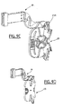
- Figure 5 shows a partial perspective view of a detail of embodiment relating to the distributor illustrated in FIGS. 3 and 4.
- Figures 6 and 7 show a perspective view and a view of above an example of a support arm for a connection base of a optical distributor according to the invention.
- Figure 8 shows a perspective view of a coiling cassette fiber of an optical distributor according to the invention.
- Figures 9 and 10 are perspective views of a module according to the invention.
- FIG. 2 An example of a multipoint optical base 6, likely to be pre-wired is illustrated, by way of example in FIG. 2.
- This base is designed to allow the individual connection of a given number of jumpers J, assumed to be composed of a single optical fiber in the example given, to a corresponding number of optical fibers F most generally from the same transmission or distribution cable of an installation.
- the garters and the fibers to which they connect are equipped additional individual connection elements.
- the garters are assumed to be fitted with male plugs connection, individual, such as the straight 8 'tubular plug mounted in end of a section of garter J in FIG.
- connection 8 complementary, here aligned, which lead to a face, called front, 9 of the base, as also seen in FIG. 2.
- a base allows for example to connect optical fibers forming part of the same group 7 and for example of a group 7 of eight fibers of a cable.
- Each connection element 8 is arranged to receive on the one hand, a fiber for example of a cable and, on the other hand, a plug terminating a fiber of garter, the two fibers coming to position end to end one by compared to each other.
- Connection plugs are for example under the form of tubular plugs, which are intended to be longitudinally each crossed by a garter fiber.
- This fiber just ended at a plug-in end of the plug it crosses and in which it is immobilized.
- This immobilization is, for example obtained by crimping.
- the plug-in end is produced in a manner known per se to position itself in a duct provided for it in an element connection 8, complementary, it is likely to be elastically retained in position in this element, after plugging in, if this is considered as preferable.
- it is provided for minus one and preferably two positioning marks 0, 0 'for each base, these marks being here constituted by two vertically holes aligned, if we consider the front face of the base as being in a vertical reference plane.
- garters which are different from those envisaged above and for example garters made up of cables comprising several fibers, fibers under loose or tight insulation, multi-fiber ribbons as part of a distributor according to the invention.
- Appropriate plugs and sockets are then provided for these different cases. Known in themselves they will not be described in detail here.
- the garters considered in the following description are considered to be each composed of a single optical fiber in the following description. It should however be understood that the invention relates to a method of jumper and distributors that can be used with garters of different types as envisaged above.
- FIG. 3 and 4 A non-limiting example of an optical distributor for installation of telecommunications, according to the invention is shown in Figures 3 and 4. It is assumed to be of large capacity and high density of elements, or points, connection and it has at least one and here two distribution bays aligned, such as 11A and 11B, which each have a set of bases, as envisioned above. These bases are intended to allow a selective interconnection between cables of transmission cables or distribution which lead to the distributor, this interconnection being carried out by means of garters whose ends are equipped with plugs compatible with the connection elements that have the bases.
- the two bays 11A, 11B are separated from each other by a patching zone 12 allowing the passage of the garters connecting the bases comprised by one of the bays with those that the other comprises, the bays being most generally specialized, one being for example assigned to the outgoing connections and the other to the arrival connections.
- the number of bays is greater than two, it is of course possible to provide for the passage of the garters, either at a single patching zone between two of the bays, or in zones each distributed between two bays, if necessary. East.
- a patching zone allowing vertical circulation of the garters on at least one of the sides of the bay.
- the bases are assumed to be of the type shown in FIG. 2, they are gathered in rows in structures with matrix look where their front faces are preferably arranged coplanar way. Locating means are provided to allow know the position of each base in the assembly formed by all manifold sub-bases and each point belonging to one of these bases and corresponding to an individual connection element.
- the bases are arranged in parallel horizontal rows which are preferably aligned from one bay to another, when there are several bays and which are identically referenced 10A or 10B, depending on the rack which contains them, in the example shown.
- the bases 6 are mounted on profiles horizontal that each of the bays have at one face, called before, two of these sections respectively referenced 13A and 13B being shown, without base, in Figure 3.
- the parallel rows of bases are interrupted at the level of the mixing zone 12 which separates the berries neighbors.
- the means for locating the positions of the bases which are provided at the distributor are for example constituted by openings regularly spaced at the step of the bases on the horizontal profiles where these bases are mounted, or possibly on elements of the distributor which are fixedly associated with these profiles and for example horizontal chutes individually associated with these profiles.
- These means marking are for example holes 67 regularly formed in the profiles or in trunking, as illustrated for 13B profiles or chutes 16B in FIG. 5. They can also be in the form notches 68 regularly produced along these profiles or chutes, as illustrated in FIG. 16, or even optical markers, for example target or barcode type.
- connection to bases 6, of fibers from different transmission and distribution cables, involves the use of means specific materials which are organized here in distribution modules and connection.
- These modules are in the form of cassettes individually articulated on individual support elements here made in the form of arms. They are housed in the internal volume proper to each of the bays so that the bases, which they carry, have their coplanar front faces.
- the interior volumes specific to the bays are delimited by the framework of beams serving as support elements and connection to the distributor, such as the vertical beams 14 and horizontal 15 of the bays 11A and 11B, in FIGS. 3 and 4.
- the sections 13A and 13B, which support the rows of bases are fixed on the vertical beams 14 framing the front face of the bay which include them.
- a horizontal chute is associated with each row base, these chutes being identically referenced 16A or 16B for the different rows, in FIG. 3, along the bay, either here 11A or 11B, that they equip.
- Each of these chutes 16A or 16B is intended to receive the optical fibers constituting the garters which are connected to the connection elements 8 of the sockets 6 whose cells are located immediately above, as shown in Figure 5 for one of the 16B trunking.
- Garter guide elements 17 are fixed on the profiles of support of the bases so as to run from top to bottom along the alveoli connection elements 8 of each base 6, above each horizontal chute. These elements are arranged to guide each garter between the trough where it comes to rest and one of the cells a base located immediately above this chute. These garter guide elements 17 are made so as to facilitate removal garters in the trunking and their adjustment in length and tension, avoiding crossings between neighboring garters, at their level.
- the patching area 12 formed between neighboring bays is here assumed to be dimensioned to allow the passage of all of the garters which are likely to be put in place to connect, each, a connection element 8 of a base 6 of a bay to an element of connection of a base of the other bay.
- This implementation is planned whatever the respective positions of the elements, of the bases which include them, and chutes associated with these bases in the bays.
- connection elements forming part of bases which are located at different heights in two bays which include them
- this circulates in a mixing zone 12, so as to pass from the vertical level of the chute which serves one of the manifolds to that of the chute serving the other.
- the set consisting of the garters passing through a patching area 12 is maintained in a determined position inside this zone 12, by means of guides here called general, such as 18A or 18B responsible for ensuring maintenance and protection of the garters.
- the general guides are here supposed to be associated in pairs, the two general guides of a pair being respectively mounted on the same level vertical on either side of a mixing zone 12 formed between two neighboring bays.
- the two general guides 18B which are represented are each located in the extension of the front edge of a chute 16B. They are intended for keep the circulating garters in the brewing zone 12 vertically at their respective levels and which pass through chutes the bay comprising the chute in the extension of which each of them is respectively located.
- Closure plates 69 carried by beams of the distributor frame limit the patching area 12 behind the general guides, as shown in figure 3.
- the bases 6 are carried by individual support arms which are fixed side by side on horizontal profiles, such as support arms 19 and 19 ' which are partially visible in Figure 5 and one of which is detailed on the Figure 6.
- Each of these support arms has a housing opening at one of its ends which is arranged to allow it to receive a base, it is here provided that the support arms are fixed on the horizontal base support profiles, as shown in figure 5 for arms 19, 19 '.
- Profiles such as 13A, 13B, are made so to allow positioning of the arms and consequently of the bases, as symbolized by the ribs 20 present on the two sections 13B, located in the high position in Figure 5.
- FIG. 6 An embodiment of a support arm 19 is illustrated in the Figures 6 and 7, as indicated above, this arm has a housing central 21 formed at a first of its ends to receive a base 6 which is positioned there precisely so that the face front and the cells of the connection elements that this base comprises, are in predetermined positions. From the moment it is planned an automated jumper between base connection elements different, it is necessary to have means to obtain the positioning of the plugs which terminate the garters in the conduits of the connection elements 8 where these plugs are to be inserted.
- means are provided for level of the end of a support arm which has a central housing 21 to cooperate with additional means provided at the level of a device by which a plug is positioned in front of the cell connection element 8 into which it must be introduced.
- the means provided at the end of an arm support are hollow forms intended to receive solid forms complementary, these forms are chosen to allow obtaining the positioning accuracy required for the introduction of a connection position in a conduit of a connection element whose position in the dispatcher has been predetermined.
- the means provided at the end of an arm of support are formed in the form of cylindrical cavities 22A which are formed at the first end of each arm and laterally each extended by a slot 22B of determined orientation.
- Base 6 is immobilized in the arm in a determined position, this positioning being confirmed by a 22C polarizer internally formed at arm level so as to enter one of the holes 0 or 0 ' which constitute the positioning marks of a base 6, when this base is in the position provided for it in the arm, the hole to be used being predetermined.
- cavities 22A are provided. arranged around the opening of the housing 21 provided for a base 6 to the first end of a support arm 19. These cavities 22A are connected two by two by a slot 22B which is common to them and which is oriented parallel to the alignment axis provided for the cells of the connection 8 of the base 6 which is housed in the arm shown.
- a rod centering preferably cylindrical and the diameter of which then corresponds to that of a cavity 22A, serves as a complementary solid form for the device designed to allow the positioning of a plug.
- This rod centering extends laterally by a projecting part whose dimensions correspond to those of a slot 22B where it comes position, when the rod which carries it is in a cavity 22A, so to provide a precise indication of positioning to the device that it team.
- a projecting part whose dimensions correspond to those of a slot 22B where it comes position, when the rod which carries it is in a cavity 22A, so to provide a precise indication of positioning to the device that it team.
- four cylindrical cavities 22A and two slots 22B are provided. support arm.
- the precise placement of the plug positioning device can be obtained by relative to one of the cylindrical cavities 22A which are arranged around the housing opening 21 of a support arm 19.
- the device position is mechanically moved to position in a predetermined way with respect to the distributor or more precisely to a connection element 8 of a base 6 precisely positioned in one of the dispatcher bays.
- the penetration of the centering rod of the plug positioning device in a cylindrical cavity 22A is then liable to be exploited incidentally for a prepositioning of the tool of this device which is used to insert a plug in the conduit of a connection element 8 determined from a base 6 determined.
- the tool is then produced in such a way that the plug has a certain possibility of accommodation and has a relative freedom of lateral movement at insertion.
- This possibility is for example the consequence of the presence of one or more springs at the level of the fixing of said tool on the device which carries it.
- the arm is doubly angled in the opposite direction at least approximately mid-length and in two dimensions, as shown in Figures 6 and 7, its two ends therefore being offset from each other, this arrangement is intended to allow high density mounting of the 19.19 'arms, bases 6 and cassettes 23 for coiling the fibers constituting the garters, at a distributor, as illustrated on the detail of realization of figure 5.
- the first end of a arm cooperates with two immediately adjacent support profiles a bay between which it plugs.
- it has two slots positioning 25 arranged to slide on ribs 20 opposite the same horizontal level which are comprised by the profiles of support between which is inserted said first arm end, the slots being shown in FIGS. 6 and 7, the ribs in FIG. 5.
- the second end of an arm has a hinge element 26 which is here constituted by a lateral axis intended to be horizontal, when the arm is in place in a distributor.
- This articulation element 26 is intended to serve as support for a cassette, as succinctly mentioned above, which has for this purpose a complementary articulation element, here of the kind carried for axis, as seen in Figure 8.
- the double folded structure which joins the two ends of a arm is here supposed to be constituted by a hollow body delimiting a channel U-shaped side which ends in the housing 20 of a base 6 to a end and by an extension of the bottom of the U which carries the element axis hinge 26.
- This lateral channel is designed to allow the passage of the group 7 of fibers which connect the connection elements of a base 6 to a coiling cassette.
- it has a labyrinth which consists of retaining tabs 27 extending above the bottom of the channel, from the two banks from which these legs project alternately from one bank to the other, so as to maintain the fibers in the channel after they are there have been introduced.
- the dimension from the end of the arm and here from its front face, in a parallel direction 13B profiles between which it is positioned is chosen double the width L of the other parts of the arm and of the cassette according to this same direction.
- This arrangement allows a gain in base density insofar as it makes it possible to alternate structures belonging to arms support on which are mounted bases 6 arranged in two immediately adjacent rows, when the bases of these rows are fix some above, others below the same 13A profile or 13B inserted between them, the corresponding arms having their elements respective 26 alternately located either above or below bases carried by the arm, when the bases are positioned in the distributor.
- this alternation also results in alternating orientations of the channels and articulation elements of the alternating support arms relating to two rows of bases immediately adjacent.
- the axes of articulation respective 26 of the different arms mounted on either side of the same profile being then all in the same alignment where they face two by of them.
- the width L allows use two rows of N bases, each in 2L steps, to align 2N cassettes in a distance of 160 mm.
- FIG. 8 A preferred embodiment of a coiling cassette 23 for fibers of a bundle is shown in Figure 8, this cassette is usually molded and made of insulating material so as to form a open case, flat bottom and here symmetrical in appearance, with respect to a plane transverse midline of trace XX.
- This case is intended to be closed by the bottom of a case, identical or similar, pressed against it, this being more especially when the cassettes are in the normal position operating in the dispatcher.
- the proposed cassette is shaped approximately rectangular since it has two symmetrically rounded corners at one of its two long sides and two spans of axis 28, 28 ', projecting, which are symmetrically arranged with respect to the transverse median plane XX, at the level of the other of these second long sides.
- the ranges 28, 28 'of a cassette are provided to come get on one or the other on an axis of articulation element 26 comprising by a support arm 19, in order to secure this arm and the cassette. They are symmetrically produced each in the form of a clamp, in the form of C, able to come elastically to position itself in force around an axis of articulation element 26 of support arm, so as to allow subsequently a rotation of the cassette relative to this axis and possibly a dissociation of the cassette and the support arm by traction on the cassette.
- a 28 or 28 'litter at each of the two ends of a cassette is not essential, it offers the advantage to allow cassettes to be aligned so that they all have their openings oriented in the same chosen direction, when they are mounted on support arms whose axes of articulation element are aligned.
- One of the senses is then given by mounting the cassettes with their respective ranges 28 each surrounding one of the aligned axes, the other direction is alternately obtained, when the cassettes have their ranges 28 ' respective surrounding each of the aligned axes.
- the aligned cassettes which are shown, are articulated on the arms of support 19, 19 'via their respective ranges 28 and the bottom of one closes the opening of the next.
- These aligned cassettes are alternately carried by support arms, the elements of which respective articulation 26, not shown in FIG. 5, are positioned lower than the bases 6 which they carry, in the distributor and the others by support arms whose respective articulation elements 26 are find themselves to be higher than the bases 6 which they carry.
- a cassette comes be housed either above a support arm against which it comes tackle by that of its short sides at the level of which is the scope by which it is articulated on this arm, when the latter has its element of articulation above the base 6 which it comprises, when it is in place in the dispatcher.
- a cassette is alternately fitted into the hollow of the elbow which is located near the articulation element of the arm of support on which it is articulated, when this arm has its element articulation below the base 6 which it comprises, when it is in place in the dispatcher.
- the dimensions chosen for the constituent elements support arms and cassettes which are brought to cooperate, when the arms are in place in the distributor and the cassettes are associated, are therefore chosen, in a manner known per se, so that the alignment cassettes are stored in the same way, while the supporting arms which carry them are arranged according to the alternative arrangement defined above.
- the articulation of a cassette on a support arm fixed in a distributor allows it to be moved between positions that correspond one at a normal operating position for which it is inserted between two other cassettes with which it is then aligned, these cassettes being carried by distributor arms mounted differently from that on which it is articulated and a position conducive to interventions for which it almost completely left the alignment of cassettes in which it is normally incorporated.
- each cassette 23 includes coiling structures 24 provided for receiving optical fibers, which are illustrated in the figure 8.
- these optical fibers comprise, on the one hand, fibers belonging to a group of fibers from a transmission cable or distribution subject to distribution, on the other hand intermediate fibers of connection of the preceding fibers to the individual connection elements 8 of the base 6 which is carried by the support arm on which the cassette is articulated.
- the coiling structures 20 of a cassette are formed by internal walls projecting from the bottom of this cassette which are arranged, manner known to the skilled person, to avoid any risk of breakage the lengths of fiber optics that are planned to be coiled in the cassette.
- Two separate conduits are provided to allow the fibers of a group and the intermediate bonding fibers to penetrate a cassette in the area where this cassette is articulated on the articulation element 26 of the support arm that carries it.
- two conduits 29 and 30 or 29 'and 30' open laterally at the ends of the cassette, in the short sides of this cassette and on either side of each of the staves of axis 28 or 28 ', only being used the channels which are close to the span axis through which the cassette is carried by an arm of support.
- the conduits 29 and 29 ′ of a cassette are arranged to allow fibers of a group to enter the cassette, in order to be connected to it each to an intermediate connecting fiber, via splices, not shown.
- This immobilizer is for example a snap-on mooring jumper, as described in connection with the figure 4, in French patent application 2789497, provided to allow immobilization of at least one tubular protective sheath in which is placed all or part of a group of fibers, as envisaged above.
- the conduits 30 and 30 'of a cassette are arranged to allow to the intermediate connecting fibers circulating in the U-shaped channel of an arm support to enter a cassette 23, articulated on this arm at one of its axis spans, by that of these conduits which adjoins this span, without risk of kinking and therefore breakage, whatever the rotation of the cassette around the axis of the articulation element of the support arm which door.
- Such rotation is possible here between the operating position and a intervention limit position which is assumed to be mechanically fixed by abutment of part of the cassette against part of the arm on which this cassette is articulated.
- the fibers input / output and the intermediate connecting fibers connected to each other at level of a cassette enter through channels 29 and 30, or 29 'and 30', which are reserved for them on both sides of the same span of axis 28 or 28 'of The tape.
- the 30 or 30 'conduit, through which the fibers penetrate intermediate links, is arranged so as to open along the extension, carrying the articulation element 26 or 26 'of the support arm against which the cassette is applied, when the latter is in position operating.
- This extension leaves a void for this purpose around the articulation element that it carries, this vacuum can be exploited for the passage of fibers, when a cassette is mounted on this element.
- splicing a fiber from a group to a fiber connecting intermediary can be achieved by various means, the form of outer is usually tubular and whose maintenance in position in the cassette is conventionally made by stacking elastic tabs 31 between which come to immobilize the various splices between fibers.
- the maintenance of the parts of fibers contained in a cassette is conventionally supplemented by means of retaining lugs 32 projecting from walls of the cassette parallel to its bottom so as to partially cover the parts of this cassette where the fibers, when coiled.
- the optical fibers from the bases 6 therefore pass through the conduits 30 and 30 'and the fibers from the cables pass through the conduits 29, 29 'or 30 and 30' depending on the optimal architecture chosen.
- the connections between the fibers can be produced by splice, unitary or grouped. In the first case, the splices are positioned between the elastic blades 31. In the second case, these blades 31 are detached from the cassette.
- the four conduits 29, 29 ', 30 and 30' are contiguous to the spans axis 28 and 28 'and thus the movements to intervene on fibers in a cassette cause negligible displacements on fibers not concerned of the cassette.
- At least part of the bases 6 provided at at least two of the bays, such as 11A and 11B in Figure 3 is initially set place before any jumper operation at the distributor which has these berries.
- the assembly 33 is here assumed to be designed to move in two directions of a plane parallel to the reference plane defined by the faces front of the bases at the front of the bays. It is for example mounted mobile in translation on a vertical support 34 which is itself provided mobile in translation in the horizontal direction and which consequently includes means of movement, here assumed to be motorized and controlled by a logic of programmed management, not shown, able to supervise the operations of garter and evolution of garter mentioned above for the entire dispatcher.
- the guide of the vertical support 34 during its horizontal movement is for example guided by rails 35 respectively arranged at the top and bottom of the distributor parallel to the reference plane defined above, as seen in Figures 3 and 4.
- FIGS. 9A to 9D the module according to the invention is described in relative positions of the arm 19 and of the different cassette 23, made possible by the characteristics of these elements.
- the cassette 23 can be positioned above the arm 19, with its bottom on the same side as the bottom of the arm ( Figure 9A) or with its bottom on the opposite side from that of the arm ( Figure 9B). Its position is stable by pressing on the arm 19.
- the cassette 23 can be positioned below the arm 19, with its bottom on the same side as the bottom of the arm ( Figure 9C) or with its bottom on the opposite side from that of the arm ( Figure 9D). Its position is then stable thanks to an arrangement to snap the cassette onto the arm (not described above) produced by a ratchet 23A carried by the cassette and snapping into an orifice arm correspondent.
- Figure 10 is an overview of the preferred method of assembly of several modules and corresponds to an assembly method of the type of that shown in Figure 5 without representation of the elements of the distributor.
Abstract
Description
L'invention concerne un module de distribution et de connexion de fibres optiques destiné à un répartiteur optique lui-même destiné à permettre les interconnexions qui sont à réaliser de manière sélective entre des liaisons par fibres optiques dans une installation de télécommunications comportant un nombre élevé de ces liaisons par fibres.The invention relates to a distribution and connection module for optical fibers intended for an optical distributor itself intended to allow the interconnections which are to be made selectively between links by optical fibers in a telecommunications installation comprising a high number of these fiber links.
Un exemple de répartiteur optique pour installation de
télécommunications est décrit dans le brevet américain 5497444. Il est
illustré sur la figure 1 et il comporte une ossature 1, d'allure rectangulaire,
qui porte une série de supports horizontaux 2 sur lesquels viennent se
positionner des modules 3, qui sont répartis sur les supports de manière à
constituer deux sous-ensembles verticaux parallèles. Chaque module est
prévu pour accueillir plusieurs raccords, chaque raccord étant prévu pour
permettre l'interconnexion de deux fibres, dont l'une est exploitée en tant
que jarretière. Une telle interconnexion entre deux fibres s'effectue par
l'intermédiaire de deux organes de connexion qui sont montés chacun à
l'extrémité d'une fibre et qui viennent se positionner à l'opposé l'un de l'autre
au niveau d'un raccord. Les organes de connexion des fibres servant de
jarretières se positionnent devant les raccords dans le répartiteur alors que
les organes de connexion des autres fibres qu'elles servent à interconnecter
sont positionnés derrière. Des éléments de guidage et de support sont
prévus pour permettre d'organiser la circulation des jarretières entre les
raccords en tenant compte des besoins futurs en matière de réorganisation,
ils sont représentés par des anneaux de passage fendus 4 et des goulottes 5,
sur la figure 1.An example of an optical distributor for installation of
telecommunications is described in US Patent 5,497,444.
illustrated in FIG. 1 and it comprises a framework 1, of rectangular appearance,
which carries a series of
Pour des raisons d'ordre et de sécurité, les jarretières circulent en général, soit horizontalement dans des goulottes horizontales et en particulier des goulottes associées aux supports horizontaux des modules, soit verticalement et plus particulièrement dans des anneaux fendus définissant un guide vertical à chacune des extrémités en largeur du répartiteur. Pour des raisons de standardisation, les jarretières optiques, qui sont usuellement produites en usine, sont généralement d'une longueur déterminée suffisante pour permettre un raccordement entre les éléments de connexion les plus éloignés du répartiteur et les jarretières unissant des éléments de connexion moins éloignés doivent être lovées de manière à loger dans le répartiteur leurs surlongueurs respectives. Ce logement s'effectue par exemple à l'intérieur ou au voisinage des guides verticaux et il doit donc être spécifiquement prévu.For reasons of order and safety, the garters circulate in general, either horizontally in horizontal troughs and in particular the chutes associated with the horizontal supports of the modules, either vertically and more particularly in split rings defining a vertical guide at each of the width ends of the distributor. For reasons of standardization, the optical jumpers, which are usually produced in the factory, are generally of a length determined sufficient to allow a connection between the elements of connection farthest from the distributor and the garters uniting less distant connection elements must be coiled so as to place their respective extra lengths in the distributor. This accommodation takes place, for example, inside or near the vertical guides and must therefore be specifically provided for.
Une telle solution qui a initialement été développée pour des jarretières constituées par des fils électriques, n'est pas satisfaisante, si le répartiteur à réaliser est un répartiteur à haute densité, de très grande capacité impliquant la mise en place d'un très grand nombre de jarretières optiques, par exemple dix mille ou plus, qui peuvent être fragiles et dont il faut éviter la détérioration, en particulier lors des modifications d'organisation.Such a solution which was initially developed for garters made up of electric wires, is not satisfactory, if the distributor to be produced is a high density distributor, of very large capacity involving the installation of a very large number of garters optical, for example ten thousand or more, which can be fragile and which avoid deterioration, especially during modifications organization.
Par ailleurs, est décrit dans le brevet US 4 585 303, un agencement de module de distribution et de connexion de fibres optiques comportant une pluralité de supports de connexion, comprenant chacun un bras creux coulissant dans un boítier et équipé à une de ses extrémités d'un connecteur et à l'autre de ses extrémités d'une cassette de lovage d'une fibre optique raccordée audit connecteur à l'intérieur dudit bras. L'autre extrémité de chaque fibre optique est raccordée au câble optique de transmission ou de distribution.Furthermore, is described in US Pat. No. 4,585,303, an arrangement of fiber optic distribution and connection module comprising a plurality of connection supports, each comprising a hollow arm sliding in a housing and fitted at one end with a connector and at the other end of an optical fiber coiling cassette connected to said connector inside said arm. The other end of each optical fiber is connected to the optical transmission or distribution.
Un tel agencement de distribution et de connexion certes compact présente les problèmes techniques suivants.Such a compact distribution and connection arrangement has the following technical issues.
Lors d'une opération sur les fibres au niveau des cassettes de lovage, le bras est coulissé à l'extérieur du boítier avec la cassette de lovage qui lui est rigidement fixée. Si grâce à la surlongueur de la fibre, cette dernière peut rester liée au câble à une de ces extrémités, le connecteur avec l'autre extrémité de la fibre est impérativement déconnecté. En d'autres termes, toute opération sur le tronçon de fibre optique située dans la cassette de lovage entraíne un déplacement de toute la fibre optique disposée dans le boítier. Ceci entraíne des interventions particulièrement lourdes.During an operation on the fibers at the coiling cassettes, the arm is slid outside of the case with the coiling cassette which is rigidly fixed. If thanks to the extra length of the fiber, the latter can stay connected to the cable at one end, the connector with the other fiber end is imperatively disconnected. In other words, any operation on the section of optical fiber located in the coiling causes a displacement of all the optical fiber arranged in the housing. This leads to particularly heavy interventions.
De plus, cet agencement connu nécessite un espace de manipulation important à l'extérieur du boítier compte tenu de l'encombrement du bras et de la cassette, lorsque ce bras est coulissé hors du boítier.In addition, this known arrangement requires handling space important outside the case given the size of the arm and of the cassette, when this arm is slid out of the housing.
L'invention résout ces problèmes en proposant un module de distribution et de connexion permettant des opérations sur la fibre optique lovée dans la cassette sans nécessité de déconnexion et sans grand encombrement, ceci tout en procurant une distribution particulièrement compacte particulièrement adaptée à un répartiteur de grande densité.The invention solves these problems by proposing a module for distribution and connection allowing operations on optical fiber coiled in the cassette without the need for disconnection and without large size, while providing a particularly distribution compact particularly suitable for a high density distributor.
Pour ce faire, l'invention propose un module de distribution et de connexion de fibres optiques destiné à un répartiteur optique, la première extrémité de chaque fibre étant raccordée à une embase de connexion et la seconde extrémité de chaque fibre étant reliée à un câble optique de transmission ou de distribution, module comportant un bras de guidage de chaque fibre fixé par sa première extrémité sur un support de rangée d'embases de connexion et relié par sa seconde extrémité à une cassette de lovage de chaque fibre, caractérisé en ce que ladite cassette de lovage est montée sur ledit bras par l'intermédiaire d'une articulation.To do this, the invention proposes a distribution and fiber optic connection for an optical splitter, the first end of each fiber being connected to a connection base and the second end of each fiber being connected to an optical cable of transmission or distribution, module comprising a guide arm of each fiber fixed by its first end on a row support connection bases and connected by its second end to a cassette coiling of each fiber, characterized in that said coiling cassette is mounted on said arm by means of a joint.
L'articulation d'une cassette sur un bras support fixé dans un répartiteur permet de la déplacer entre des positions qui correspondent l'une à une position normale d'exploitation pour laquelle elle est insérée entre deux autres cassettes avec lesquelles elle est alors alignée et une position propice aux interventions pour laquelle elle est quasi totalement sortie de l'alignement de cassettes dans lequel elle est normalement incorporée.The articulation of a cassette on a support arm fixed in a distributor allows it to be moved between positions that correspond to one at a normal operating position for which it is inserted between two other cassettes with which it is then aligned and a position conducive to interventions for which it is almost completely out of the alignment of cassettes in which it is normally incorporated.
Selon un mode de réalisation préféré de l'invention, ledit bras est fixe. According to a preferred embodiment of the invention, said arm is fixed.
Selon un mode de réalisation préféré, ledit bras comporte, à sa seconde extrémité, un élément d'articulation pour ladite cassette constitué d'un pivot horizontal.According to a preferred embodiment, said arm comprises, at its second end, an articulation element for said cassette constituted of a horizontal pivot.
De préférence, ce pivot fait saillie latéralement d'un prolongement plan du fond d'un canal en U que forme le bras.Preferably, this pivot projects laterally from an extension plan of the bottom of a U-shaped channel formed by the arm.
Ce canal en U est destiné au passage et au maintien en place de fibres intermédiaires de liaison entre les éléments individuels de connexion de l'embase, logée dans le bras, et les fibres de liaison, qui proviennent de câbles de transmission ou de distribution aboutissant au répartiteur et qui ont une extrémité lovée reliée par une épissure à une desdites fibres intermédiaires de liaison dans la cassette de lovage que porte le bras.This U-shaped channel is intended for the passage and holding in place of intermediate bonding fibers between the individual connection elements of the base, housed in the arm, and the connecting fibers, which come from transmission or distribution cables leading to the distributor and which have a coiled end connected by a splice to one of said fibers linking intermediaries in the coiling cassette carried by the arm.
Cet élément d'articulation faisant saillie latéralement d'un prolongement plan du fond du canal en U pour fibres intermédiaires que forme le bras, permet de libérer le passage pour ces fibres intermédiaires vers l'intérieur de la cassette que porte le bras, quelle que soit la position de cette cassette par rapport au bras qui la porte.This articulation element projecting laterally from a plan extension of the bottom of the U-shaped channel for intermediate fibers than forms the arm, frees the passage for these intermediate fibers towards the inside of the cassette carried by the arm, whatever the position of this cassette in relation to the arm that carries it.
Selon un mode de réalisation préféré, ladite cassette comporte un élément d'articulation, formé d'une portée pour pivot, complémentaire de l'élément d'articulation porté par le bras de support.According to a preferred embodiment, said cassette comprises a articulation element, formed by a pivot bearing, complementary to the articulation element carried by the support arm.
Avantageusement, l'élément d'articulation complémentaire porté par la dite cassette est entouré par deux conduits pour fibre, un premier de ces conduits, réalisé vers l'intérieur de la cassette par rapport à l'autre et à l'élément d'articulation complémentaire qu'il jouxte, étant destiné au passage de la fibre vers le bras portant la cassette, lorsque celle-ci est portée par l'intermédiaire de l'élément d'articulation complémentaire que ce premier conduit jouxte, le second de ces conduits, réalisé vers l'extérieur de la cassette par rapport au premier conduit et à l'élément d'articulation complémentaire qu'il jouxte, étant destiné au passage des fibres émanant de câbles de transmission ou de distribution qui sont raccordées à la cassette. Advantageously, the complementary articulation element carried by said cassette is surrounded by two fiber conduits, a first of these conduits, made towards the inside of the cassette with respect to each other and to the complementary articulation element which it adjoins, being intended for the passage of the fiber towards the arm carrying the cassette, when the latter is carried by through the complementary hinge element that this first adjacent duct, the second of these conduits, directed towards the outside of the cassette with respect to the first conduit and the articulation element which it adjoins, being intended for the passage of fibers emanating from transmission or distribution cables which are connected to the cassette.
Il est ainsi prévu que les fibres d'entrée/sortie et les fibres intermédiaires de liaison reliées entre elles au niveau d'une cassette pénètrent par des canaux qui leur sont réservés de part et d'autre d'une même portée d'axe de la cassetteIt is thus provided that the input / output fibers and the fibers connecting intermediaries linked together at a cassette enter through channels reserved for them on either side of a same axis of the cassette
De préférence, ladite cassette comporte deux éléments d'articulation, symétriquement disposés par rapport au plan transversal au niveau des extrémités d'un des grands côtés du boítier que forme la, la cassette s'articulant par l'un ou l'autre de ces deux éléments d'articulation complémentaires suivant le montage prévu pour le bras.Preferably, said cassette comprises two articulation elements, symmetrically arranged with respect to the transverse plane at the level of ends of one of the long sides of the case formed by the cassette articulated by one or the other of these two articulation elements additional depending on the mounting provided for the arm.
Avantageusement, ledit bras est doublement coudé en sens inverse dans deux dimensions et de préférence à mi-longueur.Advantageously, said arm is doubly bent in the opposite direction in two dimensions and preferably mid-length.
Les bras constituant les éléments individuels de support des embases et les cassettes de lovage au niveau d'une baie sont agencés pour pouvoir être assemblés par groupes rassemblant chacun les embases de deux rangées voisines qui sont fixées chacune sur deux supports parallèles dont l'un leur est commun et au long duquel les bras sont alternativement positionnés, l'un en dessus et le suivant en dessous.The arms constituting the individual support elements of the bases and the coiling cassettes at bay level are arranged to be able to be assembled in groups each bringing together the bases of two neighboring rows which are each fixed on two parallel supports of which one is common to them and along which the arms are alternately positioned, one above and the next below.
Lesdits bras, identiques entre eux, étant doublement coudés en sens inverse dans deux dimensions permettent aux cassettes de lovage, respectivement portées par des bras alternés de part et d'autre d'un des supports parallèles qui est commun à un groupe, d'être disposées dans un même alignement à l'intérieur de la baie, lorsqu'elles sont en position d'exploitation, du fait de l'alignement des éléments d'articulation pour cassettes que comportent ces bras alternés de part et d'autre d'un même support commun et des dimensionnements respectifs des cassettes et des bras.Said arms, identical to each other, being doubly bent in direction reverse in two dimensions allow the coiling tapes, respectively carried by alternating arms on either side of one of the parallel supports which is common to a group, to be arranged in a same alignment inside the bay, when in position due to the alignment of the articulation elements for cassettes that these arms alternate on either side of the same common support and respective sizes of cassettes and arms.
Cette courbure suivant deux axes perpendiculaires du bras permet un agencement de deux bras superposés tête-bêche dans une largeur limitée aux pas de positionnement d'un module. This curvature along two perpendicular axes of the arm allows an arrangement of two arms overlapping head to tail in a limited width at the positioning steps of a module.
Avantageusement, ladite cassette de lovage porte un cliquet d'encliquetage destiné à coopérer avec un orifice correspondant du bras.Advantageously, said coiling cassette carries a pawl latching intended to cooperate with a corresponding orifice of the arm.
L'invention, ses caractéristiques et ses avantages sont précisés dans la description qui suit en liaison avec les figures évoquées ci-dessous.The invention, its characteristics and its advantages are specified in the description which follows in conjunction with the figures mentioned below.
La figure 1 correspond à une vue en perspective du répartiteur optique connu succinctement décrit ci-dessus.Figure 1 corresponds to a perspective view of the distributor known optics succinctly described above.
La figure 2 présente un exemple d'une embase de connexion connue et d'une fiche, tels qu'envisagées dans un répartiteur selon l'invention.Figure 2 shows an example of a known connection base and a plug, as envisaged in a distributor according to the invention.
La figure 3 présente une vue de face d'un répartiteur optique selon l'invention.FIG. 3 presents a front view of an optical distributor according to the invention.
La figure 4 présente une vue de droite du répartiteur optique de la figure 2.Figure 4 shows a right view of the optical distributor of the figure 2.
La figure 5 présente une vue partielle en perspective d'un détail de réalisation relatif au répartiteur illustré sur les figures 3 et 4.Figure 5 shows a partial perspective view of a detail of embodiment relating to the distributor illustrated in FIGS. 3 and 4.
Les figures 6 et 7 présentent une vue en perspective et une vue de dessus d'un exemple de bras de support pour embase de connexion d'un répartiteur optique selon l'invention.Figures 6 and 7 show a perspective view and a view of above an example of a support arm for a connection base of a optical distributor according to the invention.
La figure 8 présente une vue en perspective d'une cassette de lovage de fibre d'un répartiteur optique selon l'invention.Figure 8 shows a perspective view of a coiling cassette fiber of an optical distributor according to the invention.
Les figures 9 et 10 sont des vues en perspective d'un module conforme à l'invention.Figures 9 and 10 are perspective views of a module according to the invention.
Un exemple d'embase optique multipoint 6, susceptible d'être précâblée est illustrée, à titre d'exemple sur la figure 2. Cette embase est prévue pour permettre le raccordement individuel d'un nombre donné de jarretières J, supposées composées d'une seule fibre optique dans l'exemple donné, à un nombre correspondant de fibres optiques F le plus généralement issues d'un même câble de transmission ou de distribution d'une installation. Les jarretières et les fibres auxquelles elles se connectent sont équipées d'éléments de connexion individuels complémentaires. Dans la réalisation envisagée ici, les jarretières sont supposées équipées de fiches mâles de connexion, individuelles, telle la fiche tubulaire rectiligne 8' montée en extrémité d'un tronçon de jarretière J sur la figure 2, alors que les fibres auxquelles ces fiches doivent se raccorder sont équipées d'éléments de connexion 8, complémentaires, ici alignés, qui débouchent au niveau d'une face, dite avant, 9 de l'embase, comme on le voit aussi sur la figure 2. Une embase permet par exemple de raccorder des fibres optiques faisant partie d'un même groupe 7 et par exemple d'un groupe 7 de huit fibres d'un câble. Chaque élément de connexion 8 est agencé pour recevoir d'une part, une fibre par exemple d'un câble et, d'autre part, une fiche terminant une fibre de jarretière, les deux fibres venant se positionner bout à bout l'une par rapport à l'autre. Les fiches de connexion se présentent par exemple sous la forme de fiches tubulaires, qui sont prévues pour être longitudinalement traversées chacune par une fibre de jarretière. Cette fibre vient se terminer au niveau d'une extrémité d'enfichage de la fiche qu'elle traverse et dans laquelle elle est immobilisée. Cette immobilisation est, par exemple obtenue par sertissage. L'extrémité d'enfichage est réalisée de manière connue en soi pour venir se positionner dans un conduit ménagé pour elle dans un élément de connexion 8, complémentaire, elle est susceptible d'être élastiquement retenue en position dans cet élément, après l'enfichage, si cela est considéré comme préférable. Selon une forme préférée de réalisation, il est prévu au moins un et préférablement deux repères de positionnement 0, 0' pour chaque embase, ces repères étant ici constitués par deux trous verticalement alignés, si l'on considère la face avant de l'embase comme étant dans un plan vertical de référence.An example of a multipoint optical base 6, likely to be pre-wired is illustrated, by way of example in FIG. 2. This base is designed to allow the individual connection of a given number of jumpers J, assumed to be composed of a single optical fiber in the example given, to a corresponding number of optical fibers F most generally from the same transmission or distribution cable of an installation. The garters and the fibers to which they connect are equipped additional individual connection elements. In the realization considered here, the garters are assumed to be fitted with male plugs connection, individual, such as the straight 8 'tubular plug mounted in end of a section of garter J in FIG. 2, while the fibers to which these plugs must be connected are fitted with connection 8, complementary, here aligned, which lead to a face, called front, 9 of the base, as also seen in FIG. 2. A base allows for example to connect optical fibers forming part of the same group 7 and for example of a group 7 of eight fibers of a cable. Each connection element 8 is arranged to receive on the one hand, a fiber for example of a cable and, on the other hand, a plug terminating a fiber of garter, the two fibers coming to position end to end one by compared to each other. Connection plugs are for example under the form of tubular plugs, which are intended to be longitudinally each crossed by a garter fiber. This fiber just ended at a plug-in end of the plug it crosses and in which it is immobilized. This immobilization is, for example obtained by crimping. The plug-in end is produced in a manner known per se to position itself in a duct provided for it in an element connection 8, complementary, it is likely to be elastically retained in position in this element, after plugging in, if this is considered as preferable. According to a preferred embodiment, it is provided for minus one and preferably two positioning marks 0, 0 'for each base, these marks being here constituted by two vertically holes aligned, if we consider the front face of the base as being in a vertical reference plane.
Il est bien entendu envisageable de mettre en oeuvre des jarretières qui soient différentes de celles envisagées ci-dessus et par exemple des jarretières constituées par des câbles comportant plusieurs fibres, des fibres sous isolation lâche ou serrée, des rubans multifibres dans le cadre d'un répartiteur selon l'invention. Des fiches et embases appropriées sont alors prévues pour ces différents cas. Connues en elles-mêmes elles ne seront pas décrites de manière détaillée ici.It is of course conceivable to use garters which are different from those envisaged above and for example garters made up of cables comprising several fibers, fibers under loose or tight insulation, multi-fiber ribbons as part of a distributor according to the invention. Appropriate plugs and sockets are then provided for these different cases. Known in themselves they will not be described in detail here.
Pour des raisons de simplification de l'exposé, les jarretières envisagées dans la suite de la description sont considérées comme composées chacune d'une seule fibre optique dans la suite de la description. Il doit cependant être entendu que l'invention se rapporte à un procédé de jarretièrage et à des répartiteurs susceptibles d'être mis en oeuvre avec des jarretières de différents types comme envisagé ci-dessus.For reasons of simplification of the presentation, the garters considered in the following description are considered to be each composed of a single optical fiber in the following description. It should however be understood that the invention relates to a method of jumper and distributors that can be used with garters of different types as envisaged above.
Un exemple non-limitatif de répartiteur optique pour installation de télécommunications, selon l'invention est présenté sur les figures 3 et 4. Il est supposé de grande capacité et à haute densité en éléments, ou points, de connexion et il comporte au moins une et ici deux baies de répartition alignées, telles 11A et 11B, qui comportent chacune un ensemble d'embases, tels qu'envisagées ci-dessus. Ces embases sont destinées à permettre une interconnexion sélective entre des fbres de câbles de transmission ou de distribution qui aboutissent au niveau du répartiteur, cette interconnexion étant réalisée par l'intermédiaire de jarretières dont les extrémités sont équipées de fiches compatibles avec les éléments de connexion que comportent les embases.A non-limiting example of an optical distributor for installation of telecommunications, according to the invention is shown in Figures 3 and 4. It is assumed to be of large capacity and high density of elements, or points, connection and it has at least one and here two distribution bays aligned, such as 11A and 11B, which each have a set of bases, as envisioned above. These bases are intended to allow a selective interconnection between cables of transmission cables or distribution which lead to the distributor, this interconnection being carried out by means of garters whose ends are equipped with plugs compatible with the connection elements that have the bases.
Dans l'exemple proposé, les deux baies 11A, 11B sont séparées l'une
de l'autre par une zone de brassage 12 permettant le passage des jarretières
reliant les embases comportées par l'une des baies avec ceux que l'autre
comporte, les baies étant le plus généralement spécialisées, l'une étant par
exemple affectée aux liaisons en départ et l'autre aux liaisons à l'arrivée.
Si le nombre de baies est plus grand que deux, il est bien entendu possible
de prévoir le passage des jarretières, soit au niveau d'une zone de brassage
unique entre deux des baies, soit dans des zones distribuées chacune entre
deux baies, si besoin est. Il doit également être compris que dans un
répartiteur constitué d'une seule baie, il est possible de prévoir une zone de
brassage permettant une circulation verticale des jarretières sur au moins un
des côtés de la baie.In the example proposed, the two
If the number of bays is greater than two, it is of course possible to provide for the passage of the garters, either at a single patching zone between two of the bays, or in zones each distributed between two bays, if necessary. East. It should also be understood that in a distributor made up of a single bay, it is possible to provide a patching zone allowing vertical circulation of the garters on at least one of the sides of the bay.
Les embases sont supposées être du type de celle qui est montrée sur la figure 2, elles sont rassemblées par rangées dans des structures à allure matricielle où leurs faces avants sont préférablement disposées de manière coplanaire. Des moyens de repérage sont prévus pour permettre de connaítre la position de chaque embase dans l'ensemble formé par toutes les embases du répartiteur et de chaque point appartenant à l'une de ces embases et correspondant à un élément de connexion individuel.The bases are assumed to be of the type shown in FIG. 2, they are gathered in rows in structures with matrix look where their front faces are preferably arranged coplanar way. Locating means are provided to allow know the position of each base in the assembly formed by all manifold sub-bases and each point belonging to one of these bases and corresponding to an individual connection element.
Comme également montré sur la figure 3, les embases sont
disposées en rangées horizontales parallèles qui sont préférablement
alignées d'une baie à l'autre, lorsqu'il y a plusieurs baies et qui sont
identiquement référencées 10A ou 10B, suivant la baie qui les comporte,
dans l'exemple présenté. Les embases 6 sont montées sur des profilés
horizontaux que comportent chacune des baies au niveau d'une face, dite
avant, deux de ces profilés respectivement référencés 13A et 13B étant
montrés, sans embase, sur la figure 3. Les rangées parallèles d'embases
s'interrompent au niveau de la zone de brassage 12 qui sépare les baies
voisines.As also shown in Figure 3, the bases are
arranged in parallel horizontal rows which are preferably
aligned from one bay to another, when there are several bays and which are
identically referenced 10A or 10B, depending on the rack which contains them,
in the example shown. The bases 6 are mounted on profiles
horizontal that each of the bays have at one face, called
before, two of these sections respectively referenced 13A and 13B being
shown, without base, in Figure 3. The parallel rows of bases
are interrupted at the level of the mixing
Les moyens de repérage des positions des embases qui sont prévus
au niveau du répartiteur sont par exemple constitués par des ouvertures
régulièrement espacées au pas des embases sur les profilés horizontaux où
sont montées ces embases, ou éventuellement sur des éléments du
répartiteur qui sont fixement associés à ces profilés et par exemple des
goulottes horizontales individuellement associées à ces profilés. Ces moyens
de repérage sont par exemple des trous 67 régulièrement ménagés dans les
profilés ou dans les goulottes, comme illustré pour les profilés 13B ou les
goulottes 16B sur la figure 5. Ils peuvent aussi se présenter sous la forme
d'encoches 68 régulièrement réalisées au long de ces profilés ou goulottes,
comme illustré sur la figure 16, ou encore de repères optiques, par exemple
de type mire ou code barre.The means for locating the positions of the bases which are provided
at the distributor are for example constituted by openings
regularly spaced at the step of the bases on the horizontal profiles where
these bases are mounted, or possibly on elements of the
distributor which are fixedly associated with these profiles and for example
horizontal chutes individually associated with these profiles. These means
marking are for example holes 67 regularly formed in the
profiles or in trunking, as illustrated for 13B profiles or
Le raccordement, aux embases 6, des fibres issues des différents
câbles de transmission et de distribution, implique l'utilisation de moyens
matériels spécifiques qui sont ici organisés en modules de distribution et
connexion. Ces modules se présentent sous la forme de cassettes
individuellement articulées sur des éléments individuels de support ici
réalisés sous la forme de bras. Ils se logent dans le volume intérieur propre à
chacune des baies de telle sorte que les embases, qu'ils portent, aient leurs
faces avants coplanaires. Les volumes intérieurs propres aux baies sont
délimités par l'ossature de poutrelles servant d'éléments de support et de
liaison au répartiteur, telles les poutrelles verticales 14 et horizontales 15 des
baies 11A et 11B, sur les figures 3 et 4. Dans l'exemple de réalisation
envisagé, les profilés 13A et 13B, qui supportent les rangées d'embases, sont
fixées sur les poutrelles verticales 14 encadrant la face avant de la baie qui
les comportent. Une goulotte horizontale est associée à chaque rangée
d'embase, ces goulottes étant identiquement référencées 16A ou 16B pour
les différentes rangées, sur la figure 3, suivant la baie, soit ici 11A ou 11B,
qu'elles équipent.The connection, to bases 6, of fibers from different
transmission and distribution cables, involves the use of means
specific materials which are organized here in distribution modules and
connection. These modules are in the form of cassettes
individually articulated on individual support elements here
made in the form of arms. They are housed in the internal volume proper to
each of the bays so that the bases, which they carry, have their
coplanar front faces. The interior volumes specific to the bays are
delimited by the framework of beams serving as support elements and
connection to the distributor, such as the
Chacune de ces goulottes 16A ou 16B est destinée à recevoir les
fibres optiques constituant les jarretières qui viennent se raccorder aux
éléments de connexion 8 des embases 6 dont les alvéoles sont situées
immédiatement au-dessus, comme le montre la figure 5 pour une des
goulottes 16B. Des éléments guide-jarretières 17 sont fixés sur les profilés de
support des embases de manière à courir de haut en bas le long des alvéoles
des éléments de connexion 8 de chaque embase 6, au-dessus de chaque
goulotte horizontale. Ces éléments sont agencés pour permettre de guider
chaque jarretière entre la goulotte où elle vient reposer et l'une des alvéoles
d'une embase située immédiatement au-dessus de cette goulotte. Ces
éléments guide-jarretières 17 sont réalisés de manière à faciliter la dépose
des jarretières dans les goulottes et leur ajustement en longueur et tension,
en évitant les croisements entre jarretières voisines, à leur niveau. Ils sont ici
légèrement recourbés de manière à guider les fibres qui les parcourent dans
la goulotte horizontale qu'ils surplombent et vers la zone de brassage 12,
située au centre du répartiteur dans l'exemple de réalisation présenté. La
zone de brassage 12 ménagée entre baies voisines, telles que 11A et 11B,
est ici supposée dimensionnée pour permettre le passage de la totalité des
jarretières qui sont susceptibles d'être mises en place pour relier, chacune,
un élément de connexion 8 d'une embase 6 d'une baie à un élément de
connexion d'une embase de l'autre baie. Cette mise en place est prévue
quelles que soient les positions respectives des éléments, des embases qui
les comportent, et des goulottes associées à ces embases dans les baies.Each of these
Lorsque deux éléments de connexion, faisant partie d'embases qui
sont situées à des hauteurs différentes dans deux baies qui les comportent,
sont reliés par une jarretière, celle-ci circule dans une zone de brassage 12,
de manière à passer du niveau vertical de la goulotte qui dessert l'une des
embases à celui de la goulotte qui dessert l'autre. L'ensemble constitué par
les jarretières transitant par une zone de brassage 12 est maintenu dans une
position déterminée à l'intérieur de cette zone 12, par l'intermédiaire de
guides ici dits généraux, tels 18A ou 18B chargés d'assurer un maintien et
une protection des jarretières. Ces guides généraux ont ici supposés réalisés
sous la forme d'éléments de forme allongée formant des bras qui sont portés
par des baies voisines de manière à venir partiellement clore la zone de
brassage 12 tout en ménageant centralement un passage d'orientation
verticale entre eux pour permettre l'introduction de fibres dans la zone,
comme on le voit sur la figure 3, pour l'exemple de réalisation présenté.When two connection elements, forming part of bases which
are located at different heights in two bays which include them,
are connected by a jumper, this circulates in a mixing
Les guides généraux sont ici supposés associés par paire, les deux
guides généraux d'une paire étant respectivement montés à un même niveau
vertical de part et d'autre d'une zone de brassage 12 ménagée entre deux
baies voisines. Dans l'exemple de réalisation illustré sur la figure 5, les deux
guides généraux 18B qui sont représentés, sont situés chacun dans le
prolongement du bord avant d'une goulotte 16B. Ils sont prévus pour
maintenir dans la zone de brassage 12, les jarretières qui circulent
verticalement à leurs niveaux respectifs et qui transitent par des goulottes de
la baie comportant la goulotte dans le prolongement de laquelle chacun
d'eux est respectivement situé. Des plaques de fermeture 69 portées par des
poutrelles de l'ossature du répartiteur limitent la zone de brassage 12
derrière les guides généraux, comme le montre la figure 3.The general guides are here supposed to be associated in pairs, the two
general guides of a pair being respectively mounted on the same level
vertical on either side of a mixing
Comme indiqué plus haut, dans l'exemple de réalisation envisagé, les
embases 6 sont portées par des bras individuels de support qui sont fixés
côte à côte sur les profilés horizontaux, comme les bras de support 19 et 19'
qui sont partiellement visibles sur la figure 5 et dont l'un est détaillé sur la
figure 6. Chacun de ces bras de support comporte un logement s'ouvrant à
une de ses extrémités qui est agencé pour lui permettre de recevoir une
embase, il est ici prévu que les bras de support viennent se fixer sur les
profilés horizontaux de support d'embases, comme illustré sur la figure 5
pour les bras 19, 19'. Les profilés tels que 13A, 13B, sont réalisés de manière
à permettre un positionnement des bras et en conséquence des embases,
comme symbolisé par les nervures 20 présentes sur les deux profilés 13B,
situés en position haute sur la figure 5.As indicated above, in the exemplary embodiment envisaged, the
bases 6 are carried by individual support arms which are fixed
side by side on horizontal profiles, such as
Une forme de réalisation d'un bras de support 19 est illustré sur les
figures 6 et 7, comme indiqué plus haut, ce bras comporte un logement
central 21 ménagé à une première de ses extrémités pour recevoir une
embase 6 qui vient s'y positionner avec précision de manière que la face
avant et les alvéoles des éléments de connexion que cette embase comporte,
soient dans des positions prédéterminées. A partir du moment où il est prévu
un jarretièrage automatisé entre éléments de connexion d'embases
différentes, il est nécessaire de disposer de moyens permettant d'obtenir le
positionnement des fiches qui terminent les jarretières dans les conduits des
éléments de connexion 8 où ces fiches doivent venir s'insérer. An embodiment of a
Dans la forme de réalisation proposée, il est prévu des moyens au
niveau de l'extrémité d'un bras de support qui comporte un logement central
21 pour coopérer avec des moyens complémentaires prévus au niveau d'un
dispositif par l'intermédiaire duquel une fiche est positionnée devant l'alvéole
d'élément de connexion 8 dans laquelle elle doit être introduite. Dans la
réalisation présentée, les moyens prévus au niveau de l'extrémité d'un bras
support sont des formes creuses destinées à recevoir des formes pleines
complémentaires, ces formes sont choisies pour permettre d'obtenir la
précision de positionnement nécessaire à l'introduction d'une fiche en
position de connexion dans un conduit d'un élément de connexion dont la
position dans le répartiteur a été prédéterminée. Dans une première variante
de réalisation, les moyens prévus au niveau de l'extrémité d'un bras de
support sont constitués sous la forme de cavités cylindriques 22A qui sont
ménagées à la première extrémité de chaque bras et latéralement
prolongées chacune par une fente 22B d'orientation déterminée. L'embase 6
est immobilisée dans le bras dans une position déterminée, ce
positionnement étant confirmé par un détrompeur 22C intérieurement
ménagé au niveau du bras de manière à pénétrer dans un des trous 0 ou 0'
qui constituent les repères de positionnement d'une embase 6, lorsque cette
embase est dans la position prévue pour elle dans le bras, le trou à utiliser
étant prédéterminé.In the proposed embodiment, means are provided for
level of the end of a support arm which has a
Dans l'exemple présenté, il est prévu quatre cavités cylindriques 22A
disposées autour de l'ouverture du logement 21 prévu pour une embase 6 à
la première extrémité d'un bras de support 19. Ces cavités 22A sont reliées
deux à deux par une fente 22B qui leur est commune et qui est orientée
parallèlement à l'axe d'alignement prévu pour les alvéoles des éléments de
connexion 8 de l'embase 6 venant se loger dans le bras représenté. Une tige
de centrage, préférablement cylindrique et dont le diamètre correspond alors
à celui d'une cavité 22A, sert de forme pleine complémentaire pour le
dispositif prévu pour permettre le positionnement d'une fiche. Cette tige de
centrage, non représentée, se prolonge latéralement par une partie saillante
dont les dimensions correspondent à celles d'une fente 22B où elle vient se
positionner, lorsque la tige qui la porte est dans une cavité 22A, de manière
à fournir une indication précise de positionnement au dispositif qu'elle
équipe. Il est ici prévu quatre cavités cylindriques 22A et deux fentes 22B par
bras de support.In the example presented, four
Dans une seconde variante de réalisation, le placement précis du
dispositif de positionnement de fiche est susceptible d'être obtenu par
rapport à une des cavités cylindriques 22A qui sont disposées autour de
l'ouverture de logement 21 d'un bras de support 19. A cet effet, le dispositif
de positionnement est mécaniquement déplacé de manière à se positionner
d'une manière prédéterminée par rapport au répartiteur ou plus précisément
à un élément de connexion 8 d'une embase 6 précisément positionnée dans
une des baies du répartiteur. La pénétration de la tige de centrage du
dispositif de positionnement de fiche dans une cavité cylindrique 22A
déterminée est alors susceptible d'être exploitée de manière accessoire pour
un prépositionnement de l'outil de ce dispositif qui sert à insérer une fiche
dans le conduit d'un élément de connexion 8 déterminé d'une embase 6
déterminée. L'outil est alors réalisé de manière que la fiche soit dotée d'une
certaine possibilité d'accommodation et possède une relative liberté de
mouvement latéral à l'insertion. Cette possibilité est par exemple la
conséquence de la présence d'un ou de plusieurs ressorts au niveau de la
fixation dudit outil, sur le dispositif qui le porte.In a second variant, the precise placement of the
plug positioning device can be obtained by
relative to one of the
Dans la forme de réalisation envisagée ici, le bras est doublement
coudé en sens inverse à au moins approximativement mi-longueur et dans
deux dimensions, comme le montrent les figures 6 et 7, ses deux extrémités
étant en conséquence décalées l'une par rapport à l'autre, cet arrangement
est destiné à permettre un montage à haute densité des bras 19,19', des
embases 6 et des cassettes 23 de lovage des fibres constituant les
jarretières, au niveau d'un répartiteur, comme illustré sur le détail de
réalisation de la figure 5.In the embodiment envisaged here, the arm is doubly
angled in the opposite direction at least approximately mid-length and in
two dimensions, as shown in Figures 6 and 7, its two ends
therefore being offset from each other, this arrangement
is intended to allow high density mounting of the 19.19 'arms,
bases 6 and
Dans une forme préférée de réalisation, la première extrémité d'un
bras vient coopérer avec deux profilés de support immédiatement voisins
d'une baie entre lesquels elle s'enfiche. A cet effet, elle comporte deux fentes
de positionnement 25 disposées de manière à coulisser sur des nervures 20
en regard de même niveau horizontal qui sont comportées par les profilés de
support entre lesquels vient s'insérer ladite première extrémité de bras, les
fentes étant montrées sur les figures 6 et 7, les nervures sur la figure 5.In a preferred embodiment, the first end of a
arm cooperates with two immediately adjacent support profiles
a bay between which it plugs. For this purpose, it has two slots
positioning 25 arranged to slide on
La seconde extrémité d'un bras comporte un élément d'articulation
26 qui est ici constitué par un axe latéral destiné à être horizontal, lorsque le
bras est en place dans un répartiteur. Cet élément d'articulation 26 est
destiné à servir de support à une cassette, telle que succinctement évoquée
plus haut, qui comporte à cet effet un élément d'articulation complémentaire,
ici du genre portée pour axe, comme on le voit sur la figure 8.The second end of an arm has a
La structure doublement repliée qui joint les deux extrémités d'un
bras est ici supposée constituée par un corps creux délimitant un canal
latéral en U qui se termine par le logement 20 d'une embase 6 à une
extrémité et par un prolongement du fond du U qui porte l'axe d'élément
d'articulation 26. Ce canal latéral est prévu pour permettre le passage du
groupe 7 de fibres qui relient les éléments de connexion d'une embase 6 à
une cassette de lovage. Il est ici doté d'un labyrinthe qui est constitué par
des pattes de maintien 27 s'étendant au-dessus du fond du canal, depuis les
deux rives duquel ces pattes saillent alternativement d'une rive vers l'autre,
de manière à assurer le maintien des fibres dans le canal après qu'elles y
aient été introduites. Dans une forme préférée de réalisation, la dimension
de l'extrémité du bras et ici de sa face avant, selon une direction parallèle
aux profilés 13B entre lesquels il se positionne, est choisie double de la
largeur L des autres parties du bras et de la cassette selon cette même
direction. Cet arrangement permet un gain en matière de densité d'embases
dans la mesure où il permet d'alterner des structures appartenant à des bras
de support sur lesquels sont montées des embases 6 disposées dans deux
rangées immédiatement voisines, lorsque les embases de ces rangées se
fixent les unes au-dessus, les autres au-dessous d'un même profilé 13A ou
13B insérés entre elles, les bras correspondants ayant leurs éléments
d'articulation 26 respectifs alternativement situés soit au-dessus, soit au-dessous
des embases que porte le bras, lorsque les embases sont
positionnées dans le répartiteur. Dans la forme de réalisation envisagée,
cette alternance se traduit aussi par des orientations alternées des canaux et
des éléments d'articulation des bras de support alternés relatifs à deux
rangées d'embases immédiatement voisines. Les axes d'articulation
respectifs 26 des différents bras montés de part et d'autre d'un même profilé
se trouvant alors tous dans le même alignement où ils se font face deux par
deux.The double folded structure which joins the two ends of a
arm is here supposed to be constituted by a hollow body delimiting a channel
U-shaped side which ends in the
Compte tenu de la densité des embases 6, de l'espacement entre deux rangées d'embases 6, qui est dans l'exemple représenté de 80 mm, et du rayon de courbure minimum des fibres optiques, la largeur L permet d'utiliser deux rangées de N embases, chacune au pas de 2L, afin d'aligner 2N cassettes dans une distance de 160 mm.Given the density of the bases 6, the spacing between two rows of bases 6, which is in the example shown 80 mm, and the minimum bending radius of the optical fibers, the width L allows use two rows of N bases, each in 2L steps, to align 2N cassettes in a distance of 160 mm.
Une forme préférée de réalisation d'une cassette de lovage 23 pour
fibres d'un faisceau est présentée sur la figure 8, cette cassette est
usuellement moulée et réalisée en matériau isolant de manière à former un
boítier ouvert, à fond plat et ici d'allure symétrique, par rapport à un plan
médian transversal de trace XX. Ce boítier est prévu pour être clos par le
fond d'un boítier, identique ou similaire, plaqué contre lui, ceci étant plus
particulièrement réalisé lorsque les cassettes sont en position normale
d'exploitation dans le répartiteur. La cassette proposée est de forme
approximativement rectangulaire dans la mesure où elle dispose de deux
coins symétriquement arrondis au niveau d'un de ses deux grands côtés et
de deux portées d'axe 28, 28', en saillie, qui sont symétriquement disposées
par rapport au plan médian transversal XX, au niveau de l'autre de ces
seconds grands côtés. Elle présente une épaisseur hors tout qui est choisie à
la largeur L de bras, évoquée plus haut, de manière qu'il soit possible
d'accoler sur une même longueur considérée au long d'un profilé de support
un nombre de cassettes correspondant au nombre de bras de support
alternés et donc au nombre d'embases portées par ces bras, ces embases
étant alternativement réparties au-dessus ou au-dessous du profilé
considéré, comme il est montré sur la figure 5.A preferred embodiment of a coiling
Les portées 28, 28' d'une cassette sont prévues pour venir
s'enfourcher l'une ou l'autre sur un axe d'élément d'articulation 26 comporté
par un bras de support 19, afin de solidariser ce bras et la cassette. Elles
sont symétriquement réalisées chacune sous la forme d'une pince, en forme
de C, apte à venir élastiquement se positionner en force autour d'un axe
d'élément d'articulation 26 de bras de support, de manière à permettre
ultérieurement une rotation de la cassette par rapport à cet axe et
éventuellement une dissociation de la cassette et du bras de support par
traction sur la cassette. La présence d'une portée 28 ou 28' à chacune des
deux extrémités d'une cassette n'est pas indispensable, elle offre l'avantage
de permettre d'aligner des cassettes de manière à ce qu'elles aient toutes
leurs ouvertures orientées dans un même sens choisi, lorsqu'elles sont
montées sur des bras de support dont les axes d'élément d'articulation sont
alignés. L'un des sens est alors donné par le montage des cassettes avec
leurs portées 28 respectives entourant chacune un des axes alignés, l'autre
sens est alternativement obtenu, lorsque les cassettes ont leurs portées 28'
respectives entourant chacune un des axes alignés.The ranges 28, 28 'of a cassette are provided to come
get on one or the other on an axis of
Dans l'exemple de réalisation, tel que proposé sur la figure 5, les
cassettes alignées, qui sont représentées, sont articulées sur les bras de
support 19, 19' par l'intermédiaire de leurs portées 28 respectives et le fond
de l'une obture l'ouverture de la suivante. Ces cassettes alignées sont
alternativement portées les unes par des bras de support dont les éléments
d'articulation 26 respectifs, non représentés sur la figure 5, sont positionnés
plus bas que les embases 6 qu'ils portent, dans le répartiteur et les autres
par des bras de support dont les éléments d'articulation 26 respectifs se
trouvent être plus hauts que les embases 6 qu'ils portent. Une cassette vient
se loger soit au-dessus d'un bras de support contre lequel elle vient se
plaquer par celui de ses petits côtés au niveau duquel se trouve la portée par
laquelle elle est articulée sur ce bras, lorsque ce dernier a son élément
d'articulation au-dessus de l'embase 6 qu'il comporte, lorsqu'il est en place
dans le répartiteur. Une cassette vient alternativement s'encastrer dans le
creux de coude qui se trouve à proximité de l'élément d'articulation du bras
de support sur lequel elle est articulée, lorsque ce bras a son élément
d'articulation au-dessous de l'embase 6 qu'il comporte, lorsqu'il est en place
dans le répartiteur. Les dimensions choisies pour les éléments constitutifs
des bras de support et des cassettes qui sont amenés à coopérer, lorsque les
bras sont en place dans le répartiteur et que les cassettes leur sont
associées, sont donc choisies, de manière connue en soi, pour que les
cassettes d'un alignement soient rangées de la même manière, alors que les
bras de support qui les portent sont disposés selon l'agencement alternatif
défini ci-dessus. L'articulation d'une cassette sur un bras support fixé dans
un répartiteur permet de la déplacer entre des positions qui correspondent
l'une à une position normale d'exploitation pour laquelle elle est insérée entre
deux autres cassettes avec lesquelles elle est alors alignée, ces cassettes
étant portées par des bras de répartiteur montés différemment de celui sur
lequel elle est articulée et une position propice aux interventions pour
laquelle elle est quasi totalement sortie de l'alignement de cassettes dans
lequel elle est normalement incorporée.In the embodiment, as proposed in FIG. 5, the
aligned cassettes, which are shown, are articulated on the arms of
Par ailleurs, chaque cassette 23 comporte des structures de lovage
24 prévues pour recevoir des fibres optiques, qui sont illustrées sur la figure
8. Pour une même cassette, ces fibres optiques comprennent, d'une part,
des fibres appartenant à un groupe de fibres issu d'un câble de transmission
ou de distribution soumis à répartition, d'autre part des fibres intermédiaires
de liaison des fibres précédentes aux éléments individuels de connexion 8 de
l'embase 6 qui est portée par le bras de support sur lequel la cassette est
articulée. Les structures de lovage 20 d'une cassette sont formées par des
parois internes en saillie sur le fond de cette cassette qui sont disposées, de
manière connue de l'homme de métier, pour éviter tout risque de cassure
aux longueurs de fibre optiques que l'on prévoit de lover dans la cassette.Furthermore, each
Deux conduits séparés sont prévus pour permettre aux fibres d'un
groupe et aux fibres intermédiaires de liaison de pénétrer dans une cassette
dans la zone où cette cassette s'articule sur l'élément d'articulation 26 du
bras de support qui la porte. Dans la réalisation présentée où la cassette
présente une symétrie par rapport à un plan médian, deux conduits 29 et 30
ou 29' et 30' s'ouvrent latéralement aux extrémités de la cassette, dans les
petits côtés de cette cassette et de part et d'autre de chacune des portées
d'axe 28 ou 28', seuls étant utilisés les canaux qui sont proches de la portée
d'axe par l'intermédiaire de laquelle la cassette est portée par un bras de
support.Two separate conduits are provided to allow the fibers of a
group and the intermediate bonding fibers to penetrate a cassette
in the area where this cassette is articulated on the
Les conduits 29 et 29' d'une cassette sont agencés pour permettre
aux fibres d'un groupe de pénétrer dans la cassette, afin d'y être raccordées
chacune à une fibre intermédiaire de liaison, par l'intermédiaire d'épissures,
non représentées.The
Il est prévu d'équiper d'un auxiliaire d'immobilisation de fibres, celui des conduits par l'intermédiaire duquel passent les fibres d'un groupe pour pénétrer dans une cassette. Cet auxiliaire d'immobilisation est par exemple un cavalier d'amarrage, encliquetable, tel que décrit en liaison avec la figure 4, dans la demande de brevet français 2789497, prévu pour permettre l'immobilisation d'au moins une gaine protectrice tubulaire dans laquelle est placé tout ou partie d'un groupe de fibres, tel qu'envisagé ci-dessus.It is planned to equip an auxiliary of immobilization of fibers, that conduits through which the fibers of a group pass for enter a cassette. This immobilizer is for example a snap-on mooring jumper, as described in connection with the figure 4, in French patent application 2789497, provided to allow immobilization of at least one tubular protective sheath in which is placed all or part of a group of fibers, as envisaged above.
Les conduits 30 et 30' d'une cassette sont agencés pour permettre
aux fibres intermédiaires de liaison circulant dans le canal en U d'un bras de
support de pénétrer dans une cassette 23, articulée sur ce bras au niveau de
l'une de ses portées d'axe, par celui de ces conduits qui voisine cette portée,
sans risque de pliure et donc de cassure, quelle que soit la rotation de la
cassette autour de l'axe de l'élément d'articulation du bras de support qui la
porte. Une telle rotation est ici possible entre la position d'exploitation et une
position limite d'intervention qui est supposée mécaniquement fixée par
butée d'une partie de la cassette contre une partie du bras sur lequel cette
cassette est articulée.The
Dans la réalisation proposée, il est prévu que les fibres
d'entrée/sortie et les fibres intermédiaires de liaison reliées entre elles au
niveau d'une cassette pénètrent par des canaux 29 et 30, ou 29' et 30', qui
leur sont réservés de part et d'autre d'une même portée d'axe 28 ou 28' de
la cassette. Le conduit 30 ou 30', par lequel pénètrent les fibres
intermédiaires de liaisons, est disposé de manière à s'ouvrir au long du
prolongement, portant l'élément d'articulation 26 ou 26' du bras de support
contre lequel vient s'appliquer la cassette, lorsque celle-ci est en position
d'exploitation. Ce prolongement laisse à cet effet subsister un vide autour de
l'élément d'articulation qu'il porte, ce vide pouvant être exploité pour le
passage de fibres, lorsqu'une cassette est montée sur cet élément.In the proposed embodiment, it is expected that the fibers
input / output and the intermediate connecting fibers connected to each other at
level of a cassette enter through
Comme connu, l'épissurage d'une fibre d'un groupe à une fibre
intermédiaire de liaison peut être réalisé par divers moyens dont la forme
extérieure est usuellement tubulaire et dont le maintien en position dans la
cassette est classiquement réalisé par un empilage de languettes élastiques
31 entre lesquelles viennent s'immobiliser les diverses épissures entre fibres.
Le maintien des parties de fibres contenues dans une cassette est
classiquement complété au moyen de pattes de maintien 32 saillant des
parois de la cassette parallèlement à son fond de manière à partiellement
couvrir les parties de cette cassette où sont susceptibles de se positionner les
fibres, lorsqu'elles sont lovées. As known, splicing a fiber from a group to a fiber
connecting intermediary can be achieved by various means, the form of
outer is usually tubular and whose maintenance in position in the
cassette is conventionally made by stacking
Les fibres optiques issues des embases 6 passent donc dans les
conduits 30 et 30' et les fibres issues des câbles passent dans les conduits
29, 29' ou 30 et 30' selon l'architecture optimale choisie. Les liaisons entre
les fibres peuvent être réalisées par des soudures épissures, unitaires ou
groupées. Dans le premier cas, les épissures sont positionnées entre les
lames élastiques 31. Dans le second cas, ces lames 31 sont détachées de la
cassette.The optical fibers from the bases 6 therefore pass through the
Les quatre conduits 29, 29', 30 et 30' sont contigus aux portées
d'axe 28 et 28' et ainsi les mouvements pour intervenir sur des fibres dans
une cassette occasionnent des déplacements négligeables sur les fibres non
concernées de la cassette.The four
Au moins une partie des embases 6 prévues au niveau d'au moins deux des baies, telles 11A et 11B sur la figure 3 est initialement mise en place avant toute opération de jarretièrage au niveau du répartiteur qui comporte ces baies. Dans la mesure où le nombre d'embases prévues dans un tel répartiteur est particulièrement élevé, il est prévu de réaliser les opérations de jarretièrage de manière automatique au moyen d'un ensemble robotisé 33 d'outillages spécialisés, apte à se déplacer devant les baies que comporte le répartiteur pour permettre aux organes d'intervenir dans le cadre des opérations nécessaires à la réalisation du jarretièrage et à son évolution au cours du temps pour chacun des points comportés par les embases 6 qui sont disposées en face avant des baies.At least part of the bases 6 provided at at least two of the bays, such as 11A and 11B in Figure 3 is initially set place before any jumper operation at the distributor which has these berries. Insofar as the number of bases provided in such a distributor is particularly high, it is planned to carry out the automatic gartering operations by means of a set robotic 33 of specialized tools, able to move in front of the bays that includes the distributor to allow the organs to intervene in the framework of operations necessary for the realization of the garter and its evolution over time for each of the points comprised by the bases 6 which are arranged on the front face of the bays.
L'ensemble 33 est ici supposé prévu pour se déplacer selon deux
directions d'un plan parallèle au plan de référence que définissent les faces
avants des embases à l'avant des baies. Il est par exemple monté mobile en
translation sur un support vertical 34 qui est lui-même prévu mobile en
translation dans le sens horizontal et qui comporte en conséquence des
moyens de déplacement, ici supposés motorisés et pilotés par une logique de
gestion programmée, non représentée, apte à superviser les opérations de
jarretièrage et d'évolution du jarretièrage évoquées ci-dessus pour
l'ensemble du répartiteur. Le guidage du support vertical 34 lors de ses
déplacements horizontaux est par exemple guidé par des rails 35
respectivement disposés en haut et en bas du répartiteur parallèlement au
plan de référence défini plus haut, comme on le voit sur les figures 3 et 4.The
Sur les figures 9A à 9D, est décrit le module conforme à l'invention
dans des positionnements relatifs du bras 19 et de la cassette 23 différents,
rendus possible grâce aux caractéristiques de ces éléments.In FIGS. 9A to 9D, the module according to the invention is described
in relative positions of the
Comme visible sur les figures 9A et 9B, la cassette 23 peut être
positionnée au-dessus du bras 19, avec son fond du même côté que le fond
du bras (figure 9A) ou avec son fond du côté opposé par rapport à celui du
bras (figure 9B). Sa position est stable par appui sur le bras 19.As shown in FIGS. 9A and 9B, the
Comme visible sur les figures 9C et 9D, la cassette 23 peut être
positionnée au-dessous du bras 19, avec son fond du même côté que le fond
du bras (figure 9C) ou avec son fond du côté opposé par rapport à celui du
bras (figure 9D). Sa position est alors stable grâce à un agencement
d'encliquetage de la cassette sur le bras (non décrit plus haut) réalisé par un
cliquet 23A porté par la cassette et venant s'encliqueter dans un orifice
correspondant du bras.As shown in FIGS. 9C and 9D, the
Grâce à la conformation symétrique de la cassette, ces différentes dispositions relatives peuvent être obtenues.Thanks to the symmetrical conformation of the cassette, these different relative provisions can be obtained.
La figure 10 est une vue d'ensemble du mode d'assemblage préféré de plusieurs modules et correspond à un mode d'assemblage du type de celui représenté sur la figure 5 sans représentation des éléments du répartiteur.Figure 10 is an overview of the preferred method of assembly of several modules and corresponds to an assembly method of the type of that shown in Figure 5 without representation of the elements of the distributor.
Comme il a déjà été explicité plus haut, grâce à l'invention, un
alignement optimalement compact est possible tout en respectant les
positions des embases de connexion et tout en bénéficiant de la possibilité
de manipuler les fibres sans démontage grâce à l'articulation entre bras 19 et
cassette 23.As has already been explained above, thanks to the invention, a
Optimally compact alignment is possible while respecting the
positions of the connection bases and while benefiting from the possibility
to handle the fibers without dismantling thanks to the articulation between
Claims (9)
Applications Claiming Priority (4)
| Application Number | Priority Date | Filing Date | Title |
|---|---|---|---|
| FR0114958 | 2001-11-13 | ||
| FR0114958A FR2832225B1 (en) | 2001-11-13 | 2001-11-13 | HIGH DENSITY OPTICAL DISTRIBUTOR AND METHOD FOR THE GARAGE OF SUCH A DISTRIBUTOR |
| FR0201732 | 2002-02-07 | ||
| FR0201732A FR2832226B1 (en) | 2001-11-13 | 2002-02-07 | OPTICAL FIBER DISTRIBUTION AND CONNECTION MODULE FOR AN OPTICAL DISTRIBUTOR |
Publications (3)
| Publication Number | Publication Date |
|---|---|
| EP1315009A2 true EP1315009A2 (en) | 2003-05-28 |
| EP1315009A3 EP1315009A3 (en) | 2003-12-17 |
| EP1315009B1 EP1315009B1 (en) | 2007-02-14 |
Family
ID=26213268
Family Applications (1)
| Application Number | Title | Priority Date | Filing Date |
|---|---|---|---|
| EP02292794A Expired - Lifetime EP1315009B1 (en) | 2001-11-13 | 2002-11-08 | Optical fibre connection and distribution module for an optical crossconnect system |
Country Status (8)
| Country | Link |
|---|---|
| US (1) | US6865330B2 (en) |
| EP (1) | EP1315009B1 (en) |
| JP (1) | JP2003222730A (en) |
| CN (1) | CN1304863C (en) |
| AT (1) | ATE354112T1 (en) |
| DE (1) | DE60218108T2 (en) |
| ES (1) | ES2280498T3 (en) |
| FR (1) | FR2832226B1 (en) |
Cited By (1)
| Publication number | Priority date | Publication date | Assignee | Title |
|---|---|---|---|---|
| WO2004049029A1 (en) * | 2002-11-22 | 2004-06-10 | Krone Gmbh | Distributor system and method for fibre optic cables |
Families Citing this family (44)
| Publication number | Priority date | Publication date | Assignee | Title |
|---|---|---|---|---|
| ES2775975T3 (en) * | 2006-09-13 | 2020-07-28 | Corning Res & Dev Corp | Fiber circuit management system with splice tray |
| CN101937120B (en) * | 2009-06-30 | 2012-05-09 | 昆山市大唐通讯设备有限公司 | Fiber non-thermal melting splicing box |
| US9229172B2 (en) | 2011-09-12 | 2016-01-05 | Commscope Technologies Llc | Bend-limited flexible optical interconnect device for signal distribution |
| US9417418B2 (en) | 2011-09-12 | 2016-08-16 | Commscope Technologies Llc | Flexible lensed optical interconnect device for signal distribution |
| US9002166B2 (en) | 2011-10-07 | 2015-04-07 | Adc Telecommunications, Inc. | Slidable fiber optic connection module with cable slack management |
| US9535229B2 (en) | 2011-10-07 | 2017-01-03 | Commscope Technologies Llc | Fiber optic cassette, system, and method |
| WO2013052854A2 (en) | 2011-10-07 | 2013-04-11 | Adc Telecommunications, Inc. | Slidable fiber optic connection module with cable slack management |
| US9170391B2 (en) | 2011-10-07 | 2015-10-27 | Adc Telecommunications, Inc. | Slidable fiber optic connection module with cable slack management |
| US9075203B2 (en) | 2012-01-17 | 2015-07-07 | Adc Telecommunications, Inc. | Fiber optic adapter block |
| US10082636B2 (en) | 2012-09-21 | 2018-09-25 | Commscope Technologies Llc | Slidable fiber optic connection module with cable slack management |
| US9195021B2 (en) | 2012-09-21 | 2015-11-24 | Adc Telecommunications, Inc. | Slidable fiber optic connection module with cable slack management |
| BR112015007015B1 (en) | 2012-09-28 | 2022-10-11 | Tyco Electronics Nederland Bv | FIBER OPTIC CASSETTE TAPE, METHOD FOR ASSEMBLING A FIBER OPTIC CASSETTE TAPE AND FLEXIBLE OPTICAL CIRCUIT |
| AU2013323664B2 (en) | 2012-09-28 | 2017-12-07 | Adc Telecommunications, Inc. | Manufacture and testing of fiber optic cassette |
| US9146374B2 (en) | 2012-09-28 | 2015-09-29 | Adc Telecommunications, Inc. | Rapid deployment packaging for optical fiber |
| US9223094B2 (en) | 2012-10-05 | 2015-12-29 | Tyco Electronics Nederland Bv | Flexible optical circuit, cassettes, and methods |
| ES2953122T3 (en) | 2013-01-29 | 2023-11-08 | CommScope Connectivity Belgium BVBA | Fiber optic distribution system |
| US9128262B2 (en) | 2013-02-05 | 2015-09-08 | Adc Telecommunications, Inc. | Slidable telecommunications tray with cable slack management |
| WO2014133943A1 (en) | 2013-02-27 | 2014-09-04 | Adc Telecommunications, Inc. | Slidable fiber optic connection module with cable slack management |
| US9435975B2 (en) * | 2013-03-15 | 2016-09-06 | Commscope Technologies Llc | Modular high density telecommunications frame and chassis system |
| WO2014173930A1 (en) | 2013-04-24 | 2014-10-30 | Tyco Electronics Raychem Bvba | Optical fiber distribution system |
| NZ713590A (en) | 2013-04-24 | 2018-09-28 | CommScope Connectivity Belgium BVBA | Universal mounting mechanism for mounting a telecommunications chassis to a telecommunications fixture |
| US9851524B2 (en) | 2014-01-28 | 2017-12-26 | Commscope Technologies Llc | Slidable fiber optic connection module with cable slack management |
| US9494758B2 (en) | 2014-04-03 | 2016-11-15 | Commscope Technologies Llc | Fiber optic distribution system |
| US10247886B2 (en) | 2014-12-10 | 2019-04-02 | Commscope Technologies Llc | Fiber optic cable slack management module |
| WO2016156611A1 (en) | 2015-04-03 | 2016-10-06 | CommScope Connectivity Belgium BVBA | Telecommunications distribution elements |
| EP3446554B1 (en) | 2016-04-19 | 2020-12-02 | CommScope, Inc. of North Carolina | Telecommunications chassis with slidable trays |
| WO2017184501A1 (en) | 2016-04-19 | 2017-10-26 | Commscope, Inc. Of North Carolina | Door assembly for a telecommunications chassis with a combination hinge structure |
| WO2018046677A1 (en) | 2016-09-08 | 2018-03-15 | CommScope Connectivity Belgium BVBA | Telecommunications distribution elements |
| US20220132229A1 (en) * | 2016-10-10 | 2022-04-28 | Telescent, Inc. | Incrementally scalable, two-tier system of robotic, fiber optic interconnect units enabling any-to-any connectivity |
| WO2018071341A2 (en) * | 2016-10-10 | 2018-04-19 | Telescent Inc. | System of large scale robotic fiber cross-connects using multi-fiber trunk reservation |
| WO2018226959A1 (en) | 2017-06-07 | 2018-12-13 | Commscope Technologies Llc | Fiber optic adapter and cassette |
| EP3692404A4 (en) | 2017-10-02 | 2021-06-16 | Commscope Technologies LLC | Fiber optic circuit and preparation method |
| US11385429B2 (en) | 2017-10-18 | 2022-07-12 | Commscope Technologies Llc | Fiber optic connection cassette |
| EP3759535A4 (en) | 2018-02-28 | 2021-11-10 | CommScope Technologies LLC | Packaging assembly for telecommunications equipment |
| US11256054B2 (en) | 2018-04-16 | 2022-02-22 | Commscope Technologies Llc | Adapter structure |
| US11635578B2 (en) | 2018-04-17 | 2023-04-25 | CommScope Connectivity Belgium BVBA | Telecommunications distribution elements |
| EP3844972B1 (en) | 2018-08-31 | 2022-08-03 | CommScope Connectivity Belgium BVBA | Frame assemblies for optical fiber distribution elements |
| EP3845044B1 (en) | 2018-08-31 | 2023-02-15 | CommScope Connectivity Belgium BVBA | Frame assemblies for optical fiber distribution elements |
| WO2020043909A1 (en) | 2018-08-31 | 2020-03-05 | CommScope Connectivity Belgium BVBA | Frame assemblies for optical fiber distribution elements |
| EP3844973A1 (en) | 2018-08-31 | 2021-07-07 | CommScope Connectivity Belgium BVBA | Frame assemblies for optical fiber distribution elements |
| EP3657068A1 (en) * | 2018-11-22 | 2020-05-27 | ZKW Group GmbH | Device for the creation and emission of light |
| EP3914947A1 (en) | 2019-01-25 | 2021-12-01 | CommScope Connectivity Belgium BVBA | Frame assemblies for optical fiber distribution elements |
| CN113534374B (en) * | 2021-06-26 | 2022-06-14 | 华为技术有限公司 | Optical fiber distribution equipment and optical fiber dispatching system |
| CN113866902B (en) * | 2021-09-30 | 2023-01-31 | 烽火通信科技股份有限公司 | Device for realizing automatic optical fiber wiring and control method thereof |
Citations (5)
| Publication number | Priority date | Publication date | Assignee | Title |
|---|---|---|---|---|
| US4585303A (en) * | 1982-08-04 | 1986-04-29 | Compagnie Industrielle Des Telecommunication Cit-Alcatel | Optical cable header |
| US5100221A (en) * | 1990-01-22 | 1992-03-31 | Porta Systems Corp. | Optical fiber cable distribution frame and support |
| US5353367A (en) * | 1993-11-29 | 1994-10-04 | Northern Telecom Limited | Distribution frame and optical connector holder combination |
| US5689606A (en) * | 1996-06-03 | 1997-11-18 | Scientific-Atlanta, Inc. | Fiber routing and retention assembly with modular fiber connector support |
| WO1998053354A1 (en) * | 1997-05-19 | 1998-11-26 | Pirelli General Plc | Connecting optical fibres |
Family Cites Families (19)
| Publication number | Priority date | Publication date | Assignee | Title |
|---|---|---|---|---|
| US4052460A (en) | 1976-01-20 | 1977-10-04 | Bayer Aktiengesellschaft | Production of 3,3-dimethyl-2-oxo-butyric acid salt |
| US4858303A (en) * | 1983-08-12 | 1989-08-22 | General Electric Company | Method of assembling a dynamoelectric machine |
| GB2198549A (en) * | 1986-12-12 | 1988-06-15 | Telephone Cables Ltd | Optical fibre distribution frame |
| US4898448A (en) * | 1988-05-02 | 1990-02-06 | Gte Products Corporation | Fiber distribution panel |
| TW232757B (en) * | 1994-01-21 | 1994-10-21 | Adc Telecommunications Inc | High-density fiber distribution frame |
| US5402515A (en) * | 1994-03-01 | 1995-03-28 | Minnesota Mining And Manufacturing Company | Fiber distribution frame system, cabinets, trays and fiber optic connector couplings |
| US5461693A (en) * | 1994-07-14 | 1995-10-24 | At&T Ipm Corp. | Optical fiber distribution frame with fiber testing |
| DE4442823A1 (en) * | 1994-12-01 | 1996-06-05 | Siemens Ag | Cassette module for optical fibers |
| JP3216692B2 (en) | 1995-01-23 | 2001-10-09 | 日本電信電話株式会社 | Optical fiber connection changing apparatus and method |
| US5631993A (en) * | 1995-04-20 | 1997-05-20 | Preformed Line Products Company | Optical fiber splice case |
| JP3148609B2 (en) | 1995-12-08 | 2001-03-19 | 株式会社フジクラ | Optical distribution frame |
| US5828807A (en) * | 1996-04-30 | 1998-10-27 | Next Level Communications | Optical network unit (ONU) mechanical enclosure |
| JPH09304631A (en) * | 1996-05-14 | 1997-11-28 | Japan Riicom:Kk | Closure for cable connection |
| JP3730337B2 (en) * | 1996-10-16 | 2006-01-05 | 株式会社ジャパンリーコム | Cable connection closure |
| FR2764995B1 (en) * | 1997-06-20 | 1999-07-23 | France Telecom | HIGH DENSITY AND HIGH CAPACITY DISTRIBUTOR, PARTICULARLY FOR OPTICAL FIBERS |
| US5987203A (en) * | 1997-10-09 | 1999-11-16 | Lucent Technologies Inc. | Distribution module for optical couplings |
| US5946440A (en) * | 1997-11-17 | 1999-08-31 | Adc Telecommunications, Inc. | Optical fiber cable management device |
| US6041155A (en) * | 1997-12-10 | 2000-03-21 | Lucent Technologies Inc. | Universal dust cover |
| FR2789497B1 (en) * | 1999-02-04 | 2002-06-14 | Cit Alcatel | OPTICAL FIBER ORGANIZER |
-
2002
- 2002-02-07 FR FR0201732A patent/FR2832226B1/en not_active Expired - Fee Related
- 2002-11-07 US US10/290,055 patent/US6865330B2/en not_active Expired - Fee Related
- 2002-11-08 EP EP02292794A patent/EP1315009B1/en not_active Expired - Lifetime
- 2002-11-08 DE DE60218108T patent/DE60218108T2/en not_active Expired - Lifetime
- 2002-11-08 ES ES02292794T patent/ES2280498T3/en not_active Expired - Lifetime
- 2002-11-08 AT AT02292794T patent/ATE354112T1/en not_active IP Right Cessation
- 2002-11-13 CN CNB021606102A patent/CN1304863C/en not_active Expired - Fee Related
- 2002-11-13 JP JP2002329540A patent/JP2003222730A/en active Pending
Patent Citations (5)
| Publication number | Priority date | Publication date | Assignee | Title |
|---|---|---|---|---|
| US4585303A (en) * | 1982-08-04 | 1986-04-29 | Compagnie Industrielle Des Telecommunication Cit-Alcatel | Optical cable header |
| US5100221A (en) * | 1990-01-22 | 1992-03-31 | Porta Systems Corp. | Optical fiber cable distribution frame and support |
| US5353367A (en) * | 1993-11-29 | 1994-10-04 | Northern Telecom Limited | Distribution frame and optical connector holder combination |
| US5689606A (en) * | 1996-06-03 | 1997-11-18 | Scientific-Atlanta, Inc. | Fiber routing and retention assembly with modular fiber connector support |
| WO1998053354A1 (en) * | 1997-05-19 | 1998-11-26 | Pirelli General Plc | Connecting optical fibres |
Cited By (2)
| Publication number | Priority date | Publication date | Assignee | Title |
|---|---|---|---|---|
| WO2004049029A1 (en) * | 2002-11-22 | 2004-06-10 | Krone Gmbh | Distributor system and method for fibre optic cables |
| US7460757B2 (en) | 2002-11-22 | 2008-12-02 | Adc Gmbh | Distributor system and method for fibre optic cables |
Also Published As
| Publication number | Publication date |
|---|---|
| DE60218108D1 (en) | 2007-03-29 |
| CN1304863C (en) | 2007-03-14 |
| ATE354112T1 (en) | 2007-03-15 |
| US20030128951A1 (en) | 2003-07-10 |
| EP1315009A3 (en) | 2003-12-17 |
| US6865330B2 (en) | 2005-03-08 |
| FR2832226B1 (en) | 2004-10-22 |
| CN1419145A (en) | 2003-05-21 |
| JP2003222730A (en) | 2003-08-08 |
| ES2280498T3 (en) | 2007-09-16 |
| DE60218108T2 (en) | 2007-11-22 |
| EP1315009B1 (en) | 2007-02-14 |
| FR2832226A1 (en) | 2003-05-16 |
Similar Documents
| Publication | Publication Date | Title |
|---|---|---|
| EP1315009B1 (en) | Optical fibre connection and distribution module for an optical crossconnect system | |
| EP0538164B1 (en) | Distribution head for high capacity optical cables | |
| FR2832225A1 (en) | Telecommunications high density fibre optic divider/interconnection method having divider bays/ central solder zone with assembly using mounting plug/cradle/connection length adjustment then position placing second plug. | |
| EP0116480B1 (en) | Connecting and mixing box for optical fibres | |
| EP0397587B1 (en) | Module and optical fiber cables connecting-box | |
| EP0464570B1 (en) | Modular device for storing reserves of transmission means in a transmission line, notably fibre optic | |
| JP4099232B2 (en) | Fiber optic organizer | |
| EP0744640B1 (en) | Connection box for optical fibres | |
| EP0348278A1 (en) | Distribution and connecting apparatus for optical fibres | |
| EP0146478A2 (en) | Joining apparatus for cables, especially optical fibres | |
| FR2590371A1 (en) | OPTICAL CABLES HEAD CHASSIS | |
| FR2531576A1 (en) | Optoelectronic connecting and interface frame. | |
| EP0479226A1 (en) | Cassette for optical junction | |
| FR2836561A1 (en) | Flat fibre optic coil winding cassette having modular cassette with base module/input winding passage and second winder with additional module and second winder having connection between winders | |
| EP2116881A1 (en) | Optical fiber distribution box | |
| EP1299759B1 (en) | Box for connecting optical fibres to workstations, for buildings | |
| FR2501381A1 (en) | DEVICE FOR FIELD CONNECTION OF TWO FIBER OPTIC TRANSMISSION CABLES | |
| FR2793890A1 (en) | ACCESS BOX FOR ONE OR MORE OPTICAL FIBERS IN A TENSIONED CABLE | |
| FR3037150A1 (en) | FIBER OPTIC LOADING CASSETTE, APPARATUS AND METHOD USING SUCH A CASSETTE | |
| EP0205363A1 (en) | Storage device for optical fibres | |
| FR2556847A1 (en) | SEMI-PERMANENT CONNECTION DEVICE FOR OPTICAL FIBERS AND METHOD FOR ITS IMPLEMENTATION | |
| FR2694642A1 (en) | Connector for transmission cable comprising several optical fibres - has support for cassette reels of optical fibre with channels to guide fibres to cable anchored below | |
| EP0803753B1 (en) | Auxiliary device for intervening and sorting fibres in an optical cable | |
| FR2743899A1 (en) | Optical fibre connection support and adjustment arranging device | |
| FR2670586A1 (en) | Connection box for fibre-optic cables |
Legal Events
| Date | Code | Title | Description |
|---|---|---|---|
| PUAI | Public reference made under article 153(3) epc to a published international application that has entered the european phase |
Free format text: ORIGINAL CODE: 0009012 |
|
| AK | Designated contracting states |
Designated state(s): AT BE BG CH CY CZ DE DK EE ES FI FR GB GR IE IT LI LU MC NL PT SE SK TR |
|
| AX | Request for extension of the european patent |
Extension state: AL LT LV MK RO SI |
|
| PUAL | Search report despatched |
Free format text: ORIGINAL CODE: 0009013 |
|
| AK | Designated contracting states |
Kind code of ref document: A3 Designated state(s): AT BE BG CH CY CZ DE DK EE ES FI FR GB GR IE IT LI LU MC NL PT SE SK TR |
|
| AX | Request for extension of the european patent |
Extension state: AL LT LV MK RO SI |
|
| 17P | Request for examination filed |
Effective date: 20040617 |
|
| AKX | Designation fees paid |
Designated state(s): AT BE BG CH CY CZ DE DK EE ES FI FR GB GR IE IT LI LU MC NL PT SE SK TR |
|
| AXX | Extension fees paid |
Extension state: SI Payment date: 20040617 Extension state: RO Payment date: 20040617 Extension state: LT Payment date: 20040617 Extension state: LV Payment date: 20040617 Extension state: AL Payment date: 20040617 Extension state: MK Payment date: 20040617 |
|
| GRAC | Information related to communication of intention to grant a patent modified |
Free format text: ORIGINAL CODE: EPIDOSCIGR1 |
|
| GRAP | Despatch of communication of intention to grant a patent |
Free format text: ORIGINAL CODE: EPIDOSNIGR1 |
|
| GRAS | Grant fee paid |
Free format text: ORIGINAL CODE: EPIDOSNIGR3 |
|
| GRAA | (expected) grant |
Free format text: ORIGINAL CODE: 0009210 |
|
| AK | Designated contracting states |
Kind code of ref document: B1 Designated state(s): AT BE BG CH CY CZ DE DK EE ES FI FR GB GR IE IT LI LU MC NL PT SE SK TR |
|
| AX | Request for extension of the european patent |
Extension state: AL LT LV MK RO SI |
|
| PG25 | Lapsed in a contracting state [announced via postgrant information from national office to epo] |
Ref country code: AT Free format text: LAPSE BECAUSE OF FAILURE TO SUBMIT A TRANSLATION OF THE DESCRIPTION OR TO PAY THE FEE WITHIN THE PRESCRIBED TIME-LIMIT Effective date: 20070214 Ref country code: IE Free format text: LAPSE BECAUSE OF FAILURE TO SUBMIT A TRANSLATION OF THE DESCRIPTION OR TO PAY THE FEE WITHIN THE PRESCRIBED TIME-LIMIT Effective date: 20070214 Ref country code: DK Free format text: LAPSE BECAUSE OF FAILURE TO SUBMIT A TRANSLATION OF THE DESCRIPTION OR TO PAY THE FEE WITHIN THE PRESCRIBED TIME-LIMIT Effective date: 20070214 Ref country code: FI Free format text: LAPSE BECAUSE OF FAILURE TO SUBMIT A TRANSLATION OF THE DESCRIPTION OR TO PAY THE FEE WITHIN THE PRESCRIBED TIME-LIMIT Effective date: 20070214 |
|
| REG | Reference to a national code |
Ref country code: GB Ref legal event code: FG4D Free format text: NOT ENGLISH |
|
| REG | Reference to a national code |
Ref country code: CH Ref legal event code: EP |
|
| REF | Corresponds to: |
Ref document number: 60218108 Country of ref document: DE Date of ref document: 20070329 Kind code of ref document: P |
|
| REG | Reference to a national code |
Ref country code: IE Ref legal event code: FG4D Free format text: LANGUAGE OF EP DOCUMENT: FRENCH |
|
| GBT | Gb: translation of ep patent filed (gb section 77(6)(a)/1977) |
Effective date: 20070410 |
|
| PG25 | Lapsed in a contracting state [announced via postgrant information from national office to epo] |
Ref country code: SE Free format text: LAPSE BECAUSE OF FAILURE TO SUBMIT A TRANSLATION OF THE DESCRIPTION OR TO PAY THE FEE WITHIN THE PRESCRIBED TIME-LIMIT Effective date: 20070514 |
|
| PG25 | Lapsed in a contracting state [announced via postgrant information from national office to epo] |
Ref country code: BG Free format text: LAPSE BECAUSE OF THE APPLICANT RENOUNCES Effective date: 20070515 |
|
| PG25 | Lapsed in a contracting state [announced via postgrant information from national office to epo] |
Ref country code: PT Free format text: LAPSE BECAUSE OF FAILURE TO SUBMIT A TRANSLATION OF THE DESCRIPTION OR TO PAY THE FEE WITHIN THE PRESCRIBED TIME-LIMIT Effective date: 20070716 |
|
| LTIE | Lt: invalidation of european patent or patent extension |
Effective date: 20070214 |
|
| REG | Reference to a national code |
Ref country code: ES Ref legal event code: FG2A Ref document number: 2280498 Country of ref document: ES Kind code of ref document: T3 |
|
| REG | Reference to a national code |
Ref country code: IE Ref legal event code: FD4D |
|
| PG25 | Lapsed in a contracting state [announced via postgrant information from national office to epo] |
Ref country code: SK Free format text: LAPSE BECAUSE OF FAILURE TO SUBMIT A TRANSLATION OF THE DESCRIPTION OR TO PAY THE FEE WITHIN THE PRESCRIBED TIME-LIMIT Effective date: 20070214 |
|
| PLBE | No opposition filed within time limit |
Free format text: ORIGINAL CODE: 0009261 |
|
| STAA | Information on the status of an ep patent application or granted ep patent |
Free format text: STATUS: NO OPPOSITION FILED WITHIN TIME LIMIT |
|
| PG25 | Lapsed in a contracting state [announced via postgrant information from national office to epo] |
Ref country code: CZ Free format text: LAPSE BECAUSE OF FAILURE TO SUBMIT A TRANSLATION OF THE DESCRIPTION OR TO PAY THE FEE WITHIN THE PRESCRIBED TIME-LIMIT Effective date: 20070214 |
|
| 26N | No opposition filed |
Effective date: 20071115 |
|
| PGFP | Annual fee paid to national office [announced via postgrant information from national office to epo] |
Ref country code: LU Payment date: 20071119 Year of fee payment: 6 |
|
| PG25 | Lapsed in a contracting state [announced via postgrant information from national office to epo] |
Ref country code: IT Free format text: LAPSE BECAUSE OF FAILURE TO SUBMIT A TRANSLATION OF THE DESCRIPTION OR TO PAY THE FEE WITHIN THE PRESCRIBED TIME-LIMIT Effective date: 20070214 Ref country code: GR Free format text: LAPSE BECAUSE OF FAILURE TO SUBMIT A TRANSLATION OF THE DESCRIPTION OR TO PAY THE FEE WITHIN THE PRESCRIBED TIME-LIMIT Effective date: 20070515 |
|
| BERE | Be: lapsed |
Owner name: NEXANS Effective date: 20071130 |
|
| PG25 | Lapsed in a contracting state [announced via postgrant information from national office to epo] |
Ref country code: MC Free format text: LAPSE BECAUSE OF NON-PAYMENT OF DUE FEES Effective date: 20071130 |
|
| PG25 | Lapsed in a contracting state [announced via postgrant information from national office to epo] |
Ref country code: LI Free format text: LAPSE BECAUSE OF NON-PAYMENT OF DUE FEES Effective date: 20071130 Ref country code: CH Free format text: LAPSE BECAUSE OF NON-PAYMENT OF DUE FEES Effective date: 20071130 |
|
| REG | Reference to a national code |
Ref country code: CH Ref legal event code: PL |
|
| PG25 | Lapsed in a contracting state [announced via postgrant information from national office to epo] |
Ref country code: BE Free format text: LAPSE BECAUSE OF NON-PAYMENT OF DUE FEES Effective date: 20071130 |
|
| PG25 | Lapsed in a contracting state [announced via postgrant information from national office to epo] |
Ref country code: EE Free format text: LAPSE BECAUSE OF FAILURE TO SUBMIT A TRANSLATION OF THE DESCRIPTION OR TO PAY THE FEE WITHIN THE PRESCRIBED TIME-LIMIT Effective date: 20070214 |
|
| PG25 | Lapsed in a contracting state [announced via postgrant information from national office to epo] |
Ref country code: CY Free format text: LAPSE BECAUSE OF FAILURE TO SUBMIT A TRANSLATION OF THE DESCRIPTION OR TO PAY THE FEE WITHIN THE PRESCRIBED TIME-LIMIT Effective date: 20070214 |
|
| PG25 | Lapsed in a contracting state [announced via postgrant information from national office to epo] |
Ref country code: TR Free format text: LAPSE BECAUSE OF FAILURE TO SUBMIT A TRANSLATION OF THE DESCRIPTION OR TO PAY THE FEE WITHIN THE PRESCRIBED TIME-LIMIT Effective date: 20070214 |
|
| PGFP | Annual fee paid to national office [announced via postgrant information from national office to epo] |
Ref country code: DE Payment date: 20091120 Year of fee payment: 8 Ref country code: ES Payment date: 20091123 Year of fee payment: 8 |
|
| PGFP | Annual fee paid to national office [announced via postgrant information from national office to epo] |
Ref country code: NL Payment date: 20091112 Year of fee payment: 8 |
|
| PGFP | Annual fee paid to national office [announced via postgrant information from national office to epo] |
Ref country code: FR Payment date: 20091201 Year of fee payment: 8 Ref country code: GB Payment date: 20091119 Year of fee payment: 8 |
|
| PG25 | Lapsed in a contracting state [announced via postgrant information from national office to epo] |
Ref country code: LU Free format text: LAPSE BECAUSE OF NON-PAYMENT OF DUE FEES Effective date: 20081108 |
|
| REG | Reference to a national code |
Ref country code: NL Ref legal event code: V1 Effective date: 20110601 |
|
| GBPC | Gb: european patent ceased through non-payment of renewal fee |
Effective date: 20101108 |
|
| REG | Reference to a national code |
Ref country code: FR Ref legal event code: ST Effective date: 20110801 |
|
| PG25 | Lapsed in a contracting state [announced via postgrant information from national office to epo] |
Ref country code: NL Free format text: LAPSE BECAUSE OF NON-PAYMENT OF DUE FEES Effective date: 20110601 |
|
| REG | Reference to a national code |
Ref country code: DE Ref legal event code: R119 Ref document number: 60218108 Country of ref document: DE Effective date: 20110601 Ref country code: DE Ref legal event code: R119 Ref document number: 60218108 Country of ref document: DE Effective date: 20110531 |
|
| PG25 | Lapsed in a contracting state [announced via postgrant information from national office to epo] |
Ref country code: FR Free format text: LAPSE BECAUSE OF NON-PAYMENT OF DUE FEES Effective date: 20101130 |
|
| PG25 | Lapsed in a contracting state [announced via postgrant information from national office to epo] |
Ref country code: GB Free format text: LAPSE BECAUSE OF NON-PAYMENT OF DUE FEES Effective date: 20101108 |
|
| REG | Reference to a national code |
Ref country code: ES Ref legal event code: FD2A Effective date: 20120110 |
|
| PG25 | Lapsed in a contracting state [announced via postgrant information from national office to epo] |
Ref country code: ES Free format text: LAPSE BECAUSE OF NON-PAYMENT OF DUE FEES Effective date: 20101109 |
|
| PG25 | Lapsed in a contracting state [announced via postgrant information from national office to epo] |
Ref country code: DE Free format text: LAPSE BECAUSE OF NON-PAYMENT OF DUE FEES Effective date: 20110531 |