EP1315049A2 - Hybrid electrophotographic apparatus for custom color printing - Google Patents
Hybrid electrophotographic apparatus for custom color printing Download PDFInfo
- Publication number
- EP1315049A2 EP1315049A2 EP02257885A EP02257885A EP1315049A2 EP 1315049 A2 EP1315049 A2 EP 1315049A2 EP 02257885 A EP02257885 A EP 02257885A EP 02257885 A EP02257885 A EP 02257885A EP 1315049 A2 EP1315049 A2 EP 1315049A2
- Authority
- EP
- European Patent Office
- Prior art keywords
- color
- image
- marking particles
- liquid
- toner
- Prior art date
- Legal status (The legal status is an assumption and is not a legal conclusion. Google has not performed a legal analysis and makes no representation as to the accuracy of the status listed.)
- Granted
Links
- 238000007639 printing Methods 0.000 title claims abstract description 30
- 239000007788 liquid Substances 0.000 claims abstract description 96
- 238000000034 method Methods 0.000 claims abstract description 38
- 239000000463 material Substances 0.000 claims description 90
- 239000002245 particle Substances 0.000 claims description 58
- 238000003384 imaging method Methods 0.000 claims description 11
- 230000003750 conditioning effect Effects 0.000 claims description 5
- 238000001035 drying Methods 0.000 claims description 2
- 238000011161 development Methods 0.000 abstract description 45
- 239000003086 colorant Substances 0.000 abstract description 27
- 239000000843 powder Substances 0.000 abstract description 17
- 238000005516 engineering process Methods 0.000 abstract description 6
- 108091008695 photoreceptors Proteins 0.000 description 31
- 239000000203 mixture Substances 0.000 description 22
- 230000008569 process Effects 0.000 description 21
- 229920005989 resin Polymers 0.000 description 13
- 239000011347 resin Substances 0.000 description 13
- PPBRXRYQALVLMV-UHFFFAOYSA-N Styrene Chemical compound C=CC1=CC=CC=C1 PPBRXRYQALVLMV-UHFFFAOYSA-N 0.000 description 12
- 238000002156 mixing Methods 0.000 description 12
- 239000012530 fluid Substances 0.000 description 11
- 239000000976 ink Substances 0.000 description 11
- 230000006870 function Effects 0.000 description 9
- 239000000049 pigment Substances 0.000 description 9
- 238000012546 transfer Methods 0.000 description 9
- 238000004140 cleaning Methods 0.000 description 8
- 230000002452 interceptive effect Effects 0.000 description 7
- 229930195733 hydrocarbon Natural products 0.000 description 6
- 150000002430 hydrocarbons Chemical class 0.000 description 6
- -1 polyethylene Polymers 0.000 description 6
- 239000012141 concentrate Substances 0.000 description 5
- 239000007787 solid Substances 0.000 description 5
- 239000000126 substance Substances 0.000 description 5
- 239000002699 waste material Substances 0.000 description 5
- 239000000654 additive Substances 0.000 description 4
- 229920001577 copolymer Polymers 0.000 description 4
- 239000006185 dispersion Substances 0.000 description 4
- 239000000975 dye Substances 0.000 description 4
- 238000012544 monitoring process Methods 0.000 description 4
- 238000012545 processing Methods 0.000 description 4
- 230000000996 additive effect Effects 0.000 description 3
- 230000001276 controlling effect Effects 0.000 description 3
- 230000009191 jumping Effects 0.000 description 3
- 238000012360 testing method Methods 0.000 description 3
- SOGAXMICEFXMKE-UHFFFAOYSA-N Butylmethacrylate Chemical compound CCCCOC(=O)C(C)=C SOGAXMICEFXMKE-UHFFFAOYSA-N 0.000 description 2
- OKTJSMMVPCPJKN-UHFFFAOYSA-N Carbon Chemical compound [C] OKTJSMMVPCPJKN-UHFFFAOYSA-N 0.000 description 2
- 239000004215 Carbon black (E152) Substances 0.000 description 2
- 241000557626 Corvus corax Species 0.000 description 2
- 229920002367 Polyisobutene Polymers 0.000 description 2
- HCHKCACWOHOZIP-UHFFFAOYSA-N Zinc Chemical compound [Zn] HCHKCACWOHOZIP-UHFFFAOYSA-N 0.000 description 2
- 229910052788 barium Inorganic materials 0.000 description 2
- DSAJWYNOEDNPEQ-UHFFFAOYSA-N barium atom Chemical compound [Ba] DSAJWYNOEDNPEQ-UHFFFAOYSA-N 0.000 description 2
- 239000000470 constituent Substances 0.000 description 2
- 238000000151 deposition Methods 0.000 description 2
- 238000011010 flushing procedure Methods 0.000 description 2
- 238000009472 formulation Methods 0.000 description 2
- MNWFXJYAOYHMED-UHFFFAOYSA-N heptanoic acid Chemical compound CCCCCCC(O)=O MNWFXJYAOYHMED-UHFFFAOYSA-N 0.000 description 2
- 238000007654 immersion Methods 0.000 description 2
- 150000002500 ions Chemical class 0.000 description 2
- 238000007726 management method Methods 0.000 description 2
- WPBNNNQJVZRUHP-UHFFFAOYSA-L manganese(2+);methyl n-[[2-(methoxycarbonylcarbamothioylamino)phenyl]carbamothioyl]carbamate;n-[2-(sulfidocarbothioylamino)ethyl]carbamodithioate Chemical class [Mn+2].[S-]C(=S)NCCNC([S-])=S.COC(=O)NC(=S)NC1=CC=CC=C1NC(=S)NC(=O)OC WPBNNNQJVZRUHP-UHFFFAOYSA-L 0.000 description 2
- 238000004519 manufacturing process Methods 0.000 description 2
- 239000003921 oil Substances 0.000 description 2
- 230000001105 regulatory effect Effects 0.000 description 2
- 150000003839 salts Chemical class 0.000 description 2
- 239000000758 substrate Substances 0.000 description 2
- KZNICNPSHKQLFF-UHFFFAOYSA-N succinimide Chemical compound O=C1CCC(=O)N1 KZNICNPSHKQLFF-UHFFFAOYSA-N 0.000 description 2
- 229920002554 vinyl polymer Polymers 0.000 description 2
- 239000011701 zinc Substances 0.000 description 2
- 229910052725 zinc Inorganic materials 0.000 description 2
- 229910052726 zirconium Inorganic materials 0.000 description 2
- IIZPXYDJLKNOIY-JXPKJXOSSA-N 1-palmitoyl-2-arachidonoyl-sn-glycero-3-phosphocholine Chemical compound CCCCCCCCCCCCCCCC(=O)OC[C@H](COP([O-])(=O)OCC[N+](C)(C)C)OC(=O)CCC\C=C/C\C=C/C\C=C/C\C=C/CCCCC IIZPXYDJLKNOIY-JXPKJXOSSA-N 0.000 description 1
- TXWSZJSDZKWQAU-UHFFFAOYSA-N 2,9-dimethyl-5,12-dihydroquinolino[2,3-b]acridine-7,14-dione Chemical compound N1C2=CC=C(C)C=C2C(=O)C2=C1C=C(C(=O)C=1C(=CC=C(C=1)C)N1)C1=C2 TXWSZJSDZKWQAU-UHFFFAOYSA-N 0.000 description 1
- IAFBRPFISOTXSO-UHFFFAOYSA-N 2-[[2-chloro-4-[3-chloro-4-[[1-(2,4-dimethylanilino)-1,3-dioxobutan-2-yl]diazenyl]phenyl]phenyl]diazenyl]-n-(2,4-dimethylphenyl)-3-oxobutanamide Chemical compound C=1C=C(C)C=C(C)C=1NC(=O)C(C(=O)C)N=NC(C(=C1)Cl)=CC=C1C(C=C1Cl)=CC=C1N=NC(C(C)=O)C(=O)NC1=CC=C(C)C=C1C IAFBRPFISOTXSO-UHFFFAOYSA-N 0.000 description 1
- CNPVJWYWYZMPDS-UHFFFAOYSA-N 2-methyldecane Chemical compound CCCCCCCCC(C)C CNPVJWYWYZMPDS-UHFFFAOYSA-N 0.000 description 1
- OYPRJOBELJOOCE-UHFFFAOYSA-N Calcium Chemical class [Ca] OYPRJOBELJOOCE-UHFFFAOYSA-N 0.000 description 1
- 229910052684 Cerium Inorganic materials 0.000 description 1
- FYYHWMGAXLPEAU-UHFFFAOYSA-N Magnesium Chemical compound [Mg] FYYHWMGAXLPEAU-UHFFFAOYSA-N 0.000 description 1
- 239000000020 Nitrocellulose Substances 0.000 description 1
- 239000002033 PVDF binder Substances 0.000 description 1
- 239000004952 Polyamide Substances 0.000 description 1
- 239000005062 Polybutadiene Substances 0.000 description 1
- 239000004698 Polyethylene Substances 0.000 description 1
- 239000004743 Polypropylene Substances 0.000 description 1
- 239000004793 Polystyrene Substances 0.000 description 1
- 239000004372 Polyvinyl alcohol Substances 0.000 description 1
- FJWGYAHXMCUOOM-QHOUIDNNSA-N [(2s,3r,4s,5r,6r)-2-[(2r,3r,4s,5r,6s)-4,5-dinitrooxy-2-(nitrooxymethyl)-6-[(2r,3r,4s,5r,6s)-4,5,6-trinitrooxy-2-(nitrooxymethyl)oxan-3-yl]oxyoxan-3-yl]oxy-3,5-dinitrooxy-6-(nitrooxymethyl)oxan-4-yl] nitrate Chemical compound O([C@@H]1O[C@@H]([C@H]([C@H](O[N+]([O-])=O)[C@H]1O[N+]([O-])=O)O[C@H]1[C@@H]([C@@H](O[N+]([O-])=O)[C@H](O[N+]([O-])=O)[C@@H](CO[N+]([O-])=O)O1)O[N+]([O-])=O)CO[N+](=O)[O-])[C@@H]1[C@@H](CO[N+]([O-])=O)O[C@@H](O[N+]([O-])=O)[C@H](O[N+]([O-])=O)[C@H]1O[N+]([O-])=O FJWGYAHXMCUOOM-QHOUIDNNSA-N 0.000 description 1
- WLKAMFOFXYCYDK-UHFFFAOYSA-N [5-amino-4-[[3-[(2-amino-4-azaniumyl-5-methylphenyl)diazenyl]-4-methylphenyl]diazenyl]-2-methylphenyl]azanium;dichloride Chemical compound [Cl-].[Cl-].CC1=CC=C(N=NC=2C(=CC([NH3+])=C(C)C=2)N)C=C1N=NC1=CC(C)=C([NH3+])C=C1N WLKAMFOFXYCYDK-UHFFFAOYSA-N 0.000 description 1
- YJVBLROMQZEFPA-UHFFFAOYSA-L acid red 26 Chemical compound [Na+].[Na+].CC1=CC(C)=CC=C1N=NC1=C(O)C(S([O-])(=O)=O)=CC2=CC(S([O-])(=O)=O)=CC=C12 YJVBLROMQZEFPA-UHFFFAOYSA-L 0.000 description 1
- 229920000122 acrylonitrile butadiene styrene Polymers 0.000 description 1
- 150000001335 aliphatic alkanes Chemical class 0.000 description 1
- XAGFODPZIPBFFR-UHFFFAOYSA-N aluminium Chemical class [Al] XAGFODPZIPBFFR-UHFFFAOYSA-N 0.000 description 1
- 229910052782 aluminium Inorganic materials 0.000 description 1
- CEGOLXSVJUTHNZ-UHFFFAOYSA-K aluminium tristearate Chemical compound [Al+3].CCCCCCCCCCCCCCCCCC([O-])=O.CCCCCCCCCCCCCCCCCC([O-])=O.CCCCCCCCCCCCCCCCCC([O-])=O CEGOLXSVJUTHNZ-UHFFFAOYSA-K 0.000 description 1
- 229940063655 aluminum stearate Drugs 0.000 description 1
- 238000013459 approach Methods 0.000 description 1
- 230000005540 biological transmission Effects 0.000 description 1
- 230000015572 biosynthetic process Effects 0.000 description 1
- 229910052791 calcium Inorganic materials 0.000 description 1
- 239000011575 calcium Substances 0.000 description 1
- 125000004432 carbon atom Chemical group C* 0.000 description 1
- 239000006229 carbon black Substances 0.000 description 1
- 235000019241 carbon black Nutrition 0.000 description 1
- 239000005018 casein Substances 0.000 description 1
- BECPQYXYKAMYBN-UHFFFAOYSA-N casein, tech. Chemical compound NCCCCC(C(O)=O)N=C(O)C(CC(O)=O)N=C(O)C(CCC(O)=N)N=C(O)C(CC(C)C)N=C(O)C(CCC(O)=O)N=C(O)C(CC(O)=O)N=C(O)C(CCC(O)=O)N=C(O)C(C(C)O)N=C(O)C(CCC(O)=N)N=C(O)C(CCC(O)=N)N=C(O)C(CCC(O)=N)N=C(O)C(CCC(O)=O)N=C(O)C(CCC(O)=O)N=C(O)C(COP(O)(O)=O)N=C(O)C(CCC(O)=N)N=C(O)C(N)CC1=CC=CC=C1 BECPQYXYKAMYBN-UHFFFAOYSA-N 0.000 description 1
- 235000021240 caseins Nutrition 0.000 description 1
- 229920002301 cellulose acetate Polymers 0.000 description 1
- ZMIGMASIKSOYAM-UHFFFAOYSA-N cerium Chemical compound [Ce][Ce][Ce][Ce][Ce][Ce][Ce][Ce][Ce][Ce][Ce][Ce][Ce][Ce][Ce][Ce][Ce][Ce][Ce][Ce][Ce][Ce][Ce][Ce][Ce][Ce][Ce][Ce][Ce][Ce][Ce][Ce][Ce][Ce][Ce][Ce][Ce][Ce] ZMIGMASIKSOYAM-UHFFFAOYSA-N 0.000 description 1
- 230000008859 change Effects 0.000 description 1
- 239000003795 chemical substances by application Substances 0.000 description 1
- 230000003749 cleanliness Effects 0.000 description 1
- 229920006026 co-polymeric resin Polymers 0.000 description 1
- 239000010941 cobalt Chemical class 0.000 description 1
- 229910017052 cobalt Inorganic materials 0.000 description 1
- GUTLYIVDDKVIGB-UHFFFAOYSA-N cobalt atom Chemical class [Co] GUTLYIVDDKVIGB-UHFFFAOYSA-N 0.000 description 1
- 238000004891 communication Methods 0.000 description 1
- 150000001875 compounds Chemical class 0.000 description 1
- GBTNCRZBGFMBGM-UHFFFAOYSA-N copper 2-ethyl-N-(2-ethylhexyl)hexan-1-amine (10Z,29Z)-2,11,20,29,38,40-hexaza-37,39-diazanidanonacyclo[28.6.1.13,10.112,19.121,28.04,9.013,18.022,27.031,36]tetraconta-1,3(40),4(9),5,7,10,12,14,16,19,21(38),22,24,26,29,31,33,35-octadecaene-6,15-disulfonic acid Chemical compound [Cu++].CCCCC(CC)CNCC(CC)CCCC.CCCCC(CC)CNCC(CC)CCCC.OS(=O)(=O)C1=CC2=C3N=C(\N=C4/[N-]C([N-]C5=N\C(=N/C6=N/C(=N\3)/c3ccc(cc63)S(O)(=O)=O)c3ccccc53)c3ccccc43)C2C=C1 GBTNCRZBGFMBGM-UHFFFAOYSA-N 0.000 description 1
- 230000007547 defect Effects 0.000 description 1
- 230000007812 deficiency Effects 0.000 description 1
- 150000001993 dienes Chemical class 0.000 description 1
- 238000007599 discharging Methods 0.000 description 1
- OOYIOIOOWUGAHD-UHFFFAOYSA-L disodium;2',4',5',7'-tetrabromo-4,5,6,7-tetrachloro-3-oxospiro[2-benzofuran-1,9'-xanthene]-3',6'-diolate Chemical compound [Na+].[Na+].O1C(=O)C(C(=C(Cl)C(Cl)=C2Cl)Cl)=C2C21C1=CC(Br)=C([O-])C(Br)=C1OC1=C(Br)C([O-])=C(Br)C=C21 OOYIOIOOWUGAHD-UHFFFAOYSA-L 0.000 description 1
- 230000000694 effects Effects 0.000 description 1
- 230000005684 electric field Effects 0.000 description 1
- 238000005265 energy consumption Methods 0.000 description 1
- 125000001495 ethyl group Chemical group [H]C([H])([H])C([H])([H])* 0.000 description 1
- 238000001704 evaporation Methods 0.000 description 1
- 230000008020 evaporation Effects 0.000 description 1
- 239000010408 film Substances 0.000 description 1
- 238000007730 finishing process Methods 0.000 description 1
- 229920002313 fluoropolymer Polymers 0.000 description 1
- 229920001519 homopolymer Polymers 0.000 description 1
- 238000005286 illumination Methods 0.000 description 1
- 229910052500 inorganic mineral Inorganic materials 0.000 description 1
- 239000000787 lecithin Substances 0.000 description 1
- 229940067606 lecithin Drugs 0.000 description 1
- 235000010445 lecithin Nutrition 0.000 description 1
- 229910052749 magnesium Inorganic materials 0.000 description 1
- 239000011777 magnesium Substances 0.000 description 1
- 238000005259 measurement Methods 0.000 description 1
- 230000007246 mechanism Effects 0.000 description 1
- 239000011707 mineral Substances 0.000 description 1
- 229920001220 nitrocellulos Polymers 0.000 description 1
- 238000007645 offset printing Methods 0.000 description 1
- 230000003287 optical effect Effects 0.000 description 1
- 239000003973 paint Substances 0.000 description 1
- 230000002093 peripheral effect Effects 0.000 description 1
- 239000003208 petroleum Substances 0.000 description 1
- 229920003227 poly(N-vinyl carbazole) Polymers 0.000 description 1
- 229920001084 poly(chloroprene) Polymers 0.000 description 1
- 229920003229 poly(methyl methacrylate) Polymers 0.000 description 1
- 229920002285 poly(styrene-co-acrylonitrile) Polymers 0.000 description 1
- 229920000058 polyacrylate Polymers 0.000 description 1
- 229920002647 polyamide Polymers 0.000 description 1
- 229920002857 polybutadiene Polymers 0.000 description 1
- 239000004417 polycarbonate Substances 0.000 description 1
- 229920000515 polycarbonate Polymers 0.000 description 1
- 229920000728 polyester Polymers 0.000 description 1
- 229920000573 polyethylene Polymers 0.000 description 1
- 229920000151 polyglycol Polymers 0.000 description 1
- 239000010695 polyglycol Substances 0.000 description 1
- 229920000642 polymer Polymers 0.000 description 1
- 239000004926 polymethyl methacrylate Substances 0.000 description 1
- 229920000098 polyolefin Polymers 0.000 description 1
- 229920001184 polypeptide Polymers 0.000 description 1
- 229920001155 polypropylene Polymers 0.000 description 1
- 229920002223 polystyrene Polymers 0.000 description 1
- 239000005077 polysulfide Substances 0.000 description 1
- 229920001021 polysulfide Polymers 0.000 description 1
- 150000008117 polysulfides Polymers 0.000 description 1
- 229920001343 polytetrafluoroethylene Polymers 0.000 description 1
- 239000004810 polytetrafluoroethylene Substances 0.000 description 1
- 229920002635 polyurethane Polymers 0.000 description 1
- 239000004814 polyurethane Substances 0.000 description 1
- 229920002451 polyvinyl alcohol Polymers 0.000 description 1
- 229920000915 polyvinyl chloride Polymers 0.000 description 1
- 239000004800 polyvinyl chloride Substances 0.000 description 1
- 229920001289 polyvinyl ether Polymers 0.000 description 1
- 229920006215 polyvinyl ketone Polymers 0.000 description 1
- 229920002981 polyvinylidene fluoride Polymers 0.000 description 1
- 239000011148 porous material Substances 0.000 description 1
- 238000004886 process control Methods 0.000 description 1
- 102000004196 processed proteins & peptides Human genes 0.000 description 1
- 108090000765 processed proteins & peptides Proteins 0.000 description 1
- 238000005086 pumping Methods 0.000 description 1
- 238000011084 recovery Methods 0.000 description 1
- 239000002904 solvent Substances 0.000 description 1
- 238000001228 spectrum Methods 0.000 description 1
- 235000015096 spirit Nutrition 0.000 description 1
- 239000007921 spray Substances 0.000 description 1
- 238000005507 spraying Methods 0.000 description 1
- 238000003860 storage Methods 0.000 description 1
- 229920003048 styrene butadiene rubber Polymers 0.000 description 1
- 238000006467 substitution reaction Methods 0.000 description 1
- 229960002317 succinimide Drugs 0.000 description 1
- 230000002459 sustained effect Effects 0.000 description 1
- 229920001169 thermoplastic Polymers 0.000 description 1
- 229920005992 thermoplastic resin Polymers 0.000 description 1
- 239000004416 thermosoftening plastic Substances 0.000 description 1
- 239000010409 thin film Substances 0.000 description 1
- 230000009466 transformation Effects 0.000 description 1
- 238000000844 transformation Methods 0.000 description 1
- 125000000391 vinyl group Chemical group [H]C([*])=C([H])[H] 0.000 description 1
- 229920001959 vinylidene polymer Polymers 0.000 description 1
- 239000001052 yellow pigment Substances 0.000 description 1
Images

Classifications
-
- G—PHYSICS
- G03—PHOTOGRAPHY; CINEMATOGRAPHY; ANALOGOUS TECHNIQUES USING WAVES OTHER THAN OPTICAL WAVES; ELECTROGRAPHY; HOLOGRAPHY
- G03G—ELECTROGRAPHY; ELECTROPHOTOGRAPHY; MAGNETOGRAPHY
- G03G15/00—Apparatus for electrographic processes using a charge pattern
- G03G15/01—Apparatus for electrographic processes using a charge pattern for producing multicoloured copies
- G03G15/0142—Structure of complete machines
- G03G15/0147—Structure of complete machines using a single reusable electrographic recording member
-
- G—PHYSICS
- G03—PHOTOGRAPHY; CINEMATOGRAPHY; ANALOGOUS TECHNIQUES USING WAVES OTHER THAN OPTICAL WAVES; ELECTROGRAPHY; HOLOGRAPHY
- G03G—ELECTROGRAPHY; ELECTROPHOTOGRAPHY; MAGNETOGRAPHY
- G03G15/00—Apparatus for electrographic processes using a charge pattern
- G03G15/01—Apparatus for electrographic processes using a charge pattern for producing multicoloured copies
- G03G15/0142—Structure of complete machines
- G03G15/0178—Structure of complete machines using more than one reusable electrographic recording member, e.g. one for every monocolour image
- G03G15/0194—Structure of complete machines using more than one reusable electrographic recording member, e.g. one for every monocolour image primary transfer to the final recording medium
-
- G—PHYSICS
- G03—PHOTOGRAPHY; CINEMATOGRAPHY; ANALOGOUS TECHNIQUES USING WAVES OTHER THAN OPTICAL WAVES; ELECTROGRAPHY; HOLOGRAPHY
- G03G—ELECTROGRAPHY; ELECTROPHOTOGRAPHY; MAGNETOGRAPHY
- G03G15/00—Apparatus for electrographic processes using a charge pattern
- G03G15/06—Apparatus for electrographic processes using a charge pattern for developing
- G03G15/10—Apparatus for electrographic processes using a charge pattern for developing using a liquid developer
Definitions
- This invention relates generally to color imaging employed in electrography, particular to a method for automatically control mixed primary colorants to match a customer-selected color which is integrated with a color applicator, such as a xerographic printer using liquid and dry xerographic toners.
- One method of printing in different colors is to uniformly charge a charge retentive surface and then expose the surface to information to be reproduced in one color. This information is rendered visible using marking particles followed by the recharging of the charge retentive surface prior to a second exposure and development.
- This recharge/expose/and develop (REaD) process may be repeated to subsequently develop images of different colors in superimposed registration on the surface before the full color image is subsequently transferred to a support substrate.
- the different colors may be developed on the photoreceptor in an image on image development process, or a highlight color image development process (image next-to image) . Each different image may be formed by using a single exposure device, e.g.
- each subsequent color image is formed in a subsequent pass of the photoreceptor (multiple pass).
- each different color image may be formed by multiple exposure devices corresponding to each different color image, during a single revolution of the photoreceptor (single pass).
- Electrostatographic printing systems typically develop an electrostatic latent image using solid toner particles either in powder form or suspended in a liquid carrier.
- the liquid developer typically has about two percent by weight toner material distributed in the liquid carrier.
- An electrostatic latent image is developed by applying the liquid developer to the photoconductive member, whereby the toner particles are selectively attracted to the surface of the photoconductive member in accordance with an electrostatic latent image.
- customer selectable color production in electrostatographic printing systems is typically carried out by providing a singular premixed developing material composition made up of a mixture of multiple color toner particles blended in preselected concentrations for producing the desired customer selectable color output.
- This method of mixing multiple color toners to produce a particular color developing material is analogous to processes used to produce customer selectable color paints and inks.
- offset printing for example, a customer selectable color output image is produced by printing a solid image pattern with a premixed customer selectable color printing ink as opposed to printing a plurality of halftone image patterns with various primary colors or compliments thereof.
- an electrostatographic printing system may be used to print various customer selectable color documents.
- replaceable containers of premixed customer selectable color developing materials corresponding to each customer selectable color are provided for each print job.
- liquid printing systems such as liquid immersion development (LID) systems
- LID liquid immersion development
- Conventional liquid printing systems can generate custom colors by combining two or more primary color toners before depositing the toners and then using the mixed toner to develop an electrostatic latent image.
- a sophisticated feedback scheme must be used to obtain accurate color reproduction and color stability.
- the differential mobility of the mixed toners often results in different consumption rates of different toner during development, requiring complex color control techniques to maintain a desired composition, e.g. color, of the toner and the color and density of the toner image created.
- the on-demand custom color capability of electrostatographic printing systems may vary significantly due to numerous conditions affecting image development, among various factors, including but certainly not limited to the methods and apparatus used to mix the primary colors to achieve the desired custom color and the process controls implemented on the color mixing and development subsystems to maintain the color accuracy and stability.
- a number of primary color developers are mixed in a reservoir with certain proportions according to the customer selection and the consumption rate of the primary colors, and then the developer mixture is applied to the latent image for development.
- Exemplary patents which may describe certain general aspects for achieving customer selectable colors, as well as specific apparatus therefor, may be U.S. Pat. No. 5,781,828 to Caruthers et al., U.S. Pat. No. 6,052,195, U.S. Pat. No. 6,049,683 as well as other patents cited therein.
- a method for creating a color image representing a document in a printing machine comprising: recording a first latent image on a charge retentive surface moving along an endless path; developing said latent image with a developer unit having developer material comprising dry marking particles of a first colored; recording a second latent image on a charge retentive surface moving along an endless path; developing said second latent image with a developer unit having developer material comprising a solution liquid carrier and marking particles of a second color.
- an apparatus for developing an image on an imaging surface comprising: a first developer unit having dry marking particles therein for developing a first portion of the image; and a second developer unit having a solution of marking particles and liquid carrier therein for developing a second portion of the image.
- a method for printing a customer selectable color image area on a latent image on a charge retentive surface moving along an endless path in a printing machine comprising: providing a plurality of developing material supply receptacles, each containing a differently colored developing material concentrate comprising marking particles and liquid carrier corresponding to basic color components of a color matching system; providing a developing material reservoir, having at least one of said plurality of developing material supply receptacles coupled thereto, for providing an operative supply of developing material; mixing selected basic color components in the developing material reservoir; supplying the mixed selected basic color components to a developer unit; developing said latent image with the developer unit, said developing step includes applying a layer of the selected basic color components onto a donor member; conditioning the layer of selected basic color components to remove the liquid carrier from the marking particles to form a layer of the marking particles.
- the electrophotographic printing machine uses a charge retentive surface in the form of a photoreceptor belt 10.
- the photoreceptor belt is supported by rollers 14, 16 and 18.
- Motor 20 operates the movement of roller 14, which in turn causes the movement of the photoreceptor in the direction indicated by arrow 12, for advancing the photoreceptor sequentially through the various xerographic stations.
- a portion of belt 10 passes through charging station A where a corona generating device, indicated generally by the reference numeral 20, charges the photoconductive surface of belt 10 to a relatively high, substantially uniform potential.
- a corona generating device indicated generally by the reference numeral 20
- the photoreceptor is negatively charged, however it is understood that the present invention could be useful with a positively charged photoreceptor, by correspondingly varying the charge levels and polarities of the toners, recharge devices, and other relevant regions or devices involved in the image on image color image formation process, as will be hereinafter described.
- RIS raster input scanner
- One common type of RIS contains document illumination lamps, optics, a mechanical scanning drive and a charged coupled device.
- the RIS captures the entire image from original document 23 and converts it to a series of raster scan lines and moreover measures a set of primary color densities, i.e. red, green and blue densities at each point of the original document.
- This information is transmitted as electrical signals to an image processing system (IPS), indicated generally by the reference numeral 24.
- IPS 24 converts the set of red, green and blue density signals to a set of colorant signals.
- multi-color image and/or text original can be externally computer generated and sent to IPS to be printed. which may include a portion image.
- the IPS contains control electronics which prepare and manage the image data flow to a raster output scanning device (ROS), indicated by numeral 28.
- a user interface (UI) indicated by 26 is in communication with IPS 24.
- UI 26 enables an operator to control the various operator adjustable functions such as selecting portion document to be printed with a custom color. The operator actuates the appropriate keys of UI 26 to adjust the parameters of the copy.
- UI 26 may be a touch screen or any other suitable control panel providing an operator interface with the system.
- the output signal from UI 26 is transmitted to the IPS 24.
- the IPS transmits signals corresponding to the desired image to ROS 28, which creates the output copy image.
- ROS 28 includes a laser with rotating polygon mirror blocks. The ROS illuminates, via mirror 29, the charged portion of a photoconductive belt 10. The ROS will expose the photoconductive belt to record single to multiple images which correspond to the signals transmitted from IPS 24.
- the photoreceptor which is initially charged to a voltage V 0 , undergoes dark decay to a level V ddp equal to about -500 volts. When exposed at the exposure station B the image areas are discharged to V DAD equal to about -50 volts. Thus after exposure, the photoreceptor contains a monopolar voltage profile of high and low voltages, the former corresponding to charged areas and the latter corresponding to discharged or image areas.
- a first development station C advances development material 35 into contact with the electrostatic latent image.
- the development housing 32 contains black toner.
- Appropriate developer biasing is accomplished via power supply 34.
- Electrical biasing is such as to effect discharged area development (DAD) of the lower (less negative) of the two voltage levels on the photoreceptor with the development material 35.
- DAD discharged area development
- This development system may be either an interactive or non-interactive system.
- a pair of corona recharge devices 41 and 42 are employed for adjusting the voltage level of both the toned and untoned areas on the photoreceptor surface to a substantially uniform level.
- the recharging devices 41 and 42 serve to substantially eliminate any voltage difference between toned areas and bare untoned areas, as well as to reduce the level of residual charge remaining on the previously toned areas, so that subsequent development of different color toner images is effected across a uniform development field.
- the first corona recharge device 41 overcharges the photoreceptor surface 10 containing previously toned and untoned areas, to a level higher than the voltage level ultimately required for V ddp , for example to -700 volts.
- the predominant corona charge delivered from corona recharge device 41 is negative.
- the second corona recharge device 42 reduces the photoreceptor surface 10 voltage to the desired V ddp , -500 volts.
- the predominant corona charge delivered from the second corona recharge device 42 is positive.
- a voltage split of 200 volts is applied to the photoreceptor surface.
- the surface 10 potential after having passed each of the two corona recharge devices, as well as the amount of voltage split of the photoreceptor, are preselected to otherwise prevent the electrical charge associated with the developed image from substantially reversing in polarity, so that the occurrence of under color splatter (UCS) is avoided.
- the corona recharge device types and the voltage split are selected to ensure that the charge at the top of the toner layer is substantially neutralized rather than driven to the reverse polarity (e.g. from negative to become substantially positive).
- the recharge devices have been described generally as corona generating devices, with reference to Figure 1.
- the recharge devices for use in the present invention could be in the form of, for example, a corotron, scorotron, dicorotron, pin scorotron, or other corona charging devices known in the art.
- the negatively charged toner is recharged by a first corona recharge device of which the predominant corona charge delivered is negative.
- a negative DC corona generating device, or an AC corona generating device biased to deliver negative current would be appropriate for such purpose.
- the second corona recharge device is required to deliver a predominantly positive charge to accomplish the objectives of the present invention, and therefore a positive DC or an AC corona generating device would be appropriate.
- a second exposure or imaging device 43 which may comprise a laser based output structure is utilized for selectively discharging the photoreceptor on toned areas and/or bare areas to approximately -50 volts, pursuant to the image to be developed with the second color developer.
- the photoreceptor contains toned and untoned areas at relatively high voltage levels (e.g. -500 volts) and toned and untoned areas at relatively low voltage levels (e.g. -50 volts). These low voltage areas represent image areas, which are to be developed using discharged area development.
- a negatively charged developer material 45 comprising, for example, yellow color toner is employed.
- the toner is contained in a developer housing structure 47 disposed at a second developer station E and is presented to the latent images on the photoreceptor by a non-interactive developer.
- a power supply (not shown) serves to electrically bias the developer structure to a level effective to develop the DAD image areas with the negatively charged yellow toner particles 45.
- a pair of corona recharge devices 51 and 52 are employed for adjusting the voltage level of both the toned and untoned areas on the photoreceptor to a substantially uniform level.
- the recharging, imaging and developing process is similar to that of stations D and E and will not be described in detail.
- This image is developed using a third color toner 55 contained in a non-interactive developer housing 57 disposed at a third developer station G.
- An example of a suitable third color toner is magenta.
- Suitable electrical biasing of the housing 57 is provided by a power supply, not shown.
- a pair of corona recharge devices 61 and 62 are employed for adjusting the voltage level of both the toned and untoned areas on the photoreceptor to a substantially uniform level.
- a fourth latent image is created using an imaging or exposure device 63.
- a fourth DAD image is formed on both bare areas and previously toned areas of the photoreceptor that are to be developed with the fourth color image.
- This image is developed, for example, using a cyan color toner 65 contained in developer housing 67 at a fourth developer station I. Suitable electrical biasing of the housing 67 is provided by a power supply, not shown.
- the present invention adds a fourth recharging station J, a pair of corona recharge devices 71 and 72 are employed for adjusting the voltage level of both the toned and untoned areas on the photoreceptor to a substantially uniform level.
- a fifth latent image is created using a ROS device 73.
- a fifth DAD image is formed on the photoreceptor that are to be developed using a custom color toner. This image is developed contained in developer housing 77 at a fifth developer station K. Suitable electrical biasing of the housing 77 is provided by a power supply, not shown.
- the developer housing structures 47, 57, and 67 are preferably of the type known in the art which do not interact, or are only marginally interactive with previously developed images.
- a DC jumping development system, a powder cloud development system, and a sparse, non-contacting magnetic brush development systems are each suitable for use in an image on image color development system.
- a non-interactive, scavengeless development housing having minimal interactive effects between previously deposited toner and subsequently presented toner is described in U.S. Patent Number 4,833,503, the relevant portions of which are hereby incorporated by reference herein.
- Toner composition in developer housing structures 47, 57, and 67 may comprise any suitable resins, with or without other internal or external additives.
- resin materials toner compositions of the present invention may utilize any of the numerous suitable resins such as thermoplastic resins known in the art to be useful in producing toners and developers.
- Suitable resins that may be utilized in the present invention include but are not limited to olefin polymers such as polyethylene, polypropylene and the like; polymers derived from dienes such as polybutadiene, polyisobutylene, polychloroprene and the like; vinyl and vinylidene polymers such as polystyrene, styrene butyl methacrylate copolymers, styrene butylacrylate copolymers, styreneacrylonitrile copolymers, acrylonitrile-butadiene styrene terpolymers, polymethylmethacrylate, polyacrylate, polyvinyl alcohol, polyvinyl chloride, polyvinyl carbazole, polyvinyl ethers, polyvinyl ketones and the like; fluorocarbon polymers such as polytetrafluoroethylene, polyvinylidene fluoride and the like; heterochain thermoplastics such as polyamides, polyesters, poly
- resins containing a relatively high percentage of styrene are preferred, such as homopolymers of styrene or styrene homologs of copolymers of styrene.
- One preferred resin used in the present invention is a copolymer resin of styrene and n-butylmethacrylate.
- Another preferred resin used in the present invention is a styrene butadiene copolymer resin with a styrene content of from about 70% to about 95% by weight, such as PLIOTONE® available from Goodyear Chemical.
- the resins are generally present in the toners of the present invention in an amount of from about 40% to about 98% by weight, and more preferably from about 70% to about 98% by weight; although they may be present in greater or lesser amounts, provided that the objectives of the present invention are achieved.
- a negative pre-transfer corotron member 80 delivers negative corona to ensure that all toner particles are of the required negative polarity to ensure proper subsequent transfer.
- a sheet of support material 82 is moved into contact with the toner images at transfer station L.
- the sheet of support material is advanced to transfer station L by conventional sheet feeding apparatus, not shown.
- the sheet feeding apparatus includes a feed roll contacting the uppermost sheet of a stack of copy sheets. The feed rolls rotate so as to advance the uppermost sheet from a stack into a chute which directs the advancing sheet of support material into contact with the photoconductive surface of belt 10 in a timed sequence so that the toner powder image developed thereon contacts the advancing sheet of support material at transfer station L.
- Transfer station L includes a transfer corona device 84 which sprays positive ions onto the backside of sheet 82. This attracts the negatively charged toner powder images from the belt 10 to sheet 82.
- a detack corona device 86 is provided for facilitating stripping of the sheets from the belt 10.
- Fusing station M includes a fuser assembly, indicated generally by the reference numeral 90, which permanently affixes the transferred powder image to sheet 82.
- fuser assembly 90 comprises a heated fuser roller 92 and a backup or pressure roller 94.
- Sheet 82 passes between fuser roller 92 and backup roller 94 with the toner powder image contacting fuser roller 92. In this manner, the toner powder images are permanently affixed to sheet 82 after it is allowed to cool.
- a chute guides the advancing sheets 82 to a catch tray, not shown, for subsequent removal from the printing machine by the operator.
- the residual toner particles carried by the non-image areas on the photoconductive surface are removed therefrom. These particles may be removed at cleaning station N using a cleaning brush structure contained in a housing 88.
- the various machine functions described hereinabove are generally managed and regulated by a controller preferably in the form of a programmable microprocessor (not shown).
- the microprocessor controller provides electrical command signals for operating all of the machine subsystems and printing operations described herein, imaging onto the photoreceptor, paper delivery, xerographic processing functions associated with developing and transferring the developed image onto the paper, and various functions associated with copy sheet transport and subsequent finishing processes.
- the various machine functions described above are generally managed and regulated by a controller which provides electrical command signals for controlling the operations described above.
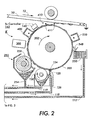
- liquid developing material is transported from an supply reservoir 150 to the donor roll or donor belt 200 via a liquid developing material applicator 125.
- Supply reservoir 150 acts as a holding receptacle for providing an operative solution of liquid developing material comprised of liquid carrier, a charge director compound, and toner material, which, in the case of the customer selectable color application of the present invention, includes a blend of different colored marking particles.
- a plurality of replaceable supply dispensers 111A-111Z each containing a concentrated supply of marking particles and carrier liquid corresponding to a basic color component in a color matching system, are provided in association with the operational supply reservoir 150 and coupled thereto for replenishing the liquid developing material therein, as will be described.
- the exemplary developing material applicator 125 includes a housing 122, having an elongated aperture 124 extending along a longitudinal axis thereof so as to be oriented substantially transverse to the surface of donor roll 200, along the direction of travel thereof (as indicated by arrow 202).
- the aperture 124 is coupled to an inlet port 126 which is further coupled to reservoir 150 via transport conduit 118.
- Transport conduit 118 operates in conjunction with aperture 124 to provide a path of travel for liquid developing material being transported from reservoir 150 and also defines a developing material application region in which the liquid developing material can freely flow in order to contact the surface of the donor roll 200.
- liquid developing material is pumped or otherwise transported from the supply reservoir 150 to the applicator 125 through at least one inlet port 126, such that the liquid developing material flows out of the elongated aperture 124 and into contact with the surface of donor roll 200.
- Such an overflow channel would be connected to an outlet channel 128 for removal of excess or extraneous liquid developing material, for flushing and cleaning with carrier fluid the developing material applicator 125, and, preferably, for directing this excess material back to reservoir 150 or to a waste sump 120 whereat the liquid developing material can preferably be collected and the components thereof can be recycled for subsequent use.
- the flushing and cleaning with carrier fluid enables automatic switching of custom colors between printing jobs.
- an electrically biased metering roll 130 Slightly downstream of and adjacent to the developing material applicator 125, in the direction of movement of the donor roll surface 200, is an electrically biased metering roll 130, the peripheral surface thereof being situated in close proximity to the surface of the donor roll 200, as shown, for example, by U.S. Pat. No. 5,974,292, among various other patents.
- the metering roller 130 rotates in a direction opposite the movement of the surface of donor roll 200 so as to apply a substantial shear force and electrical bias to the thin layer of liquid developing material present in the area of the nip between the metering roller 130 and the donor roll 200, for minimizing the thickness of the liquid developing material on the surface thereof.
- Condition system 250 compress the liquid toner layer and remove some of the liquid carrier therefrom, as shown, for example, by U.S. Pat. No. 4,286,039, among various other patents.
- Condition system 250 comprising a roller, similar to roller 258 which may include a porous body and a perforated skin covering.
- the roller 258 is typically biased to a potential having a polarity which inhibits the departure of toner particles from the liquid toner layer on the donor roll while compacting the toner particles onto the surface of the donor roll 200.
- a vacuum source (not shown) is also provided and coupled to the interior of the roller for creating an airflow through the porous roller body to draw liquid from the surface of the donor roll, thereby increasing the percentage of toner solids on donor roll 200.
- roller 258 rotates with the donor roll 250 such that the porous body of roller 258 absorbs excess liquid from the surface liquid toner layer through the pores and perforations of the roller skin covering.
- the vacuum source typically located along one end of a central cavity, draws liquid through the roller skin to a central cavity for depositing the liquid in a receptacle or some other location which permits either disposal or recirculation of the liquid carrier.
- the porous roller 258 is thus continuously discharged of excess liquid to provide continuous removal of liquid from donor roll 200.
- the liquid toner layer has a percentage of toner solids between 50 and 80 percent.
- the discharged of excess liquid carrier is removed from condition system 250 through outlet port 254 which couples to reservoir 150 or a waste sump (not shown) via transport conduit 119.
- Dry condition system 300 contains a carrier fluid recovery device that condenses the carrier fluid and a port and conduit to recycle the carrier fluid to the carrier fluid reservoir for further use.
- Corona device 400 may be in the form of an AC or DC charging device (e.g. scorotron).
- the now charged toner layer is moved into development zone 410, defined by the gap between donor 200 and the surface of the photoreceptor belt 10.
- the toner layer on the donor roll is then disturbed by electric fields from a wire or set of wires 411so as to produce an agitated cloud of toner particles.
- the cloud is also sustained by the AC voltage applied to the wires in the form of a square wave.
- Typical signal magnitudes are 700-900 Vpp at frequencies of 3-10 kHz. Toner from the cloud is then developed onto the nearby photoreceptor by fields created by a latent image. It should be noted that other forms of AC or DC jumping development system, a powder cloud development system, or fluidized bed development could be employed.
- Cleaning device 550 cleans donor roll 200 by using a cleaning blade or an electrostatic brush or a combination of both and spraying liquid developer fluid onto donor roll 200.
- Cleaning device 350 has a dispersing device that facilitates the dispersion of the toner in the carrier fluid. The excess developing material eventually falls away from the rotating metering roll for collection in the reservoir 150 or a waste sump (not shown) via transport conduit 117.
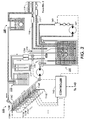
- reservoir 150 is continuously replenished, as necessary, by the addition of developing material or selective components thereof, for example in the case of liquid developing materials, by the addition of liquid carrier, marking particles, and/or charge director into the supply reservoir 150. Since the total amount of any one component making up the developing material utilized to develop the image may vary as a function of the area of the developed image areas and the background portions of the latent image on the photoconductive surface, the specific amount of each of each component of the liquid developing material which must be added to the supply reservoir 150 varies with each development cycle.
- a print job having a developed image having a large proportion of printed image area will cause a greater depletion of marking particles and/or charge director from a developing material reservoir as compared to a print job having a developed image with a small amount of printed image area.
- the rate of replenishment of the liquid carrier component of the liquid developing material may be controlled by simply monitoring the level of liquid developer in the supply reservoir 150, the rate of replenishment of the marking particles, and/or the charge director components of the liquid developing material in reservoir 150 must be controlled in a more sophisticated manner to maintain a the correct concentration for proper functionality of the marking particles and the charge director in the operative solution stored in the supply reservoir 150 (although that concentration may vary with time due to changes in operational parameters).
- the replenishment system of the present invention includes a plurality of differently colored developing material supply dispensers 111, 111B, 111C, . . . 111Z, each coupled to the operative supply reservoir via a respective associated valve member 116A, 116B 116C . . .
- each supply dispenser contains a developing material concentrate of a known basic or primary color such as Cyan, Magenta, Yellow and Black.
- the replenishment system includes eighteen supply dispensers, wherein each supply container provides a different basic color liquid developing material corresponding to the eighteen basic or constituent colors of the PANTONE® Color Matching System used for custom color printing and process color printing.
- This embodiment contemplates that color formulations conveniently provided by the PANTONE® System can be utilized, as for example, by storage in a look up table, to produce thousands of desirable output colors and shades in a customer selectable color printing.
- Using this system as few as two different color liquid developing materials, from supply containers 111A and 111B for example, can be combined in reservoir 150 to expand the color gamut of customer selectable colors far beyond the colors available via half tone imaging techniques.
- An essential component of the liquid developing material color mixing and control system of the present invention is a color control system. That is, since different components of the blended liquid developing material in reservoir 150 may develop at different rates, a customer selectable color mixing controller 142 is provided in order to determine appropriate amounts of each color liquid developing material in supply containers 111A, 111B . . . or 111Z to be added to supply reservoir 150, and to controllably supply each of such appropriate amounts of liquid developing material.
- Controller 142 may take the form of any known microprocessor based memory and processing device, as are well known in the art.
- the approach provided by the color mixing control system of the present invention includes a sensing device 140, for example, an optical sensor for monitoring the output color of the toner layer on donor roll.
- Sensor 140 is connected to controller 142 for providing sensed color information thereto, which, in turn is used for controlling the flow of the variously colored replenishing liquid developing materials from dispensers 111A-111Z, carrier fluid dispenser 115, and a charge control additive, sometimes referred to as a charge director, dispenser 117.
- the colored developing materials in dispensers 111A-111Z correspond to the basic constituent colors of a color matching system, and are selectively delivered into the liquid developing material supply reservoir 150 from each of the supply containers 111A-111Z to produce the customer selectable color output image.
- a Smart Ink Management System (SIMS) controller 142 is coupled to control valves 116A-116Z, 115A and 117A for selective actuation thereof to control the flow of liquid developing material from each supply container 111A-111Z, 115 and 117.
- SIMS Smart Ink Management System
- these valves may be replaced by pump devices or any other suitable flow control mechanisms as known in the art, so as to be substituted thereby.
- color accuracy is maintained by monitoring and sensing the color toner layer on donor roll 200 and or of the developer material in the container 150.
- an area identified in an image as corresponding to the customer selectable color may be monitored and sensed in a manner similar to the process disclosed in U.S.
- Pat. No. 5,450,165 so as to obviate the need for the printing of a test image.
- Monitoring of the color output image for color accuracy can be facilitated by sensor 140 such as a colorimeter of the type known in the art utilizing any technique for measuring color and sensor 141 such as a spectrophotometer is used to provide the real time measurement of the transmission or reflection spectrum of liquid developer as prints are made.
- Additional sensors include thermometer 170, to monitor the temperature of the developer material in container 150, height sensor 175, which measures the volume of the developer material in container 150 by measuring the height and the dimensions of the container, and conductimeter 160, which measures the conductivity of the developer material. All of these sensor and the color sensor described below provide feedback signals to the controller 142.
- Sensors 140 and 141 senses the actual color, and in turn, provides an image feedback signal to controller 142, the signal being processed by conventional electronic circuitry in order to selectively control the operation of valves 116A-116Z, 115A and 117A.
- each selected developing material concentrate is preferably dispensed in a relatively small amount into the reservoir 150 where it is thoroughly mixed with the developing material therein to produce the desired customer selectable color developing material.
- sensor 140 can take various forms and could be of many types as are well known in the art.
- the color is typically defined in terms of a particular color coordinate system, such as, for example, the well recognized standardized color notation system for defining uniform color spaces developed by the Commission Internationale de l'Eclairage (CIE).
- CIE Commission Internationale de l'Eclairage
- the CIE color specification system employs so called "tristimulus values" to specify colors and to establish device independent color spaces.
- the CIE standards are widely accepted because measured colors can be readily expressed in the CIE recommended coordinate systems through the use of relatively straight-forward mathematical transformations.
- controller 142 for selectively actuating valves 116-116Z and 115A to systematically dispense to the reservoir 150 selective amounts of liquid developing material concentrate corresponding to selected basic color components from selected supply dispensers 111A-111Z and liquid carrier dispenser 115.
- the required concentration levels of each basic color component required to generate any given color may be stored in a look up table in processor 142.
- the measured color of a test image is transformed into its tristimulus values and compared to the tristimulus values of the desired output color. The differential result of this comparison is then transformed to provide the precise amounts of each basic color component necessary to modify the operative supply of developing material to yield the desired output color.
- the mixture of toner particles and liquid carrier in supply dispensers 111A-111Z is between 8-25 percent by weight, although this amount may vary from this range provided that the objectives of the present invention are achieved.
- liquid carrier medium is present in a large amount in the developer composition, and constitutes that percentage by weight of the developer not accounted for by the other components.
- the liquid medium is usually present in an amount of from about 80 to about 98 percent by weight, although this amount may vary from this range provided that the objectives of the present invention are achieved.
- the liquid carrier medium may be selected from a wide variety of materials, including, but not limited to, any of several hydrocarbon liquids conventionally employed for liquid development processes, including hydrocarbons, such as high purity alkanes having from about 6 to about 14 carbon atoms, such as NORPAR® 12, NORPAR® 13, and NORPAR® 15, and including isoparaffinic hydrocarbons such as ISOPAR® G, H, L, and M, available from Exxon Corporation.
- hydrocarbons such as high purity alkanes having from about 6 to about 14 carbon atoms, such as NORPAR® 12, NORPAR® 13, and NORPAR® 15, and including isoparaffinic hydrocarbons such as ISOPAR® G, H, L, and M, available from Exxon Corporation.
- liquid carrier examples include AMSCO® 460 Solvent, AMSCO® OMS, available from American Mineral Spirits Company, SOLTROL®, available from Phillips Petroleum Company, PAGASOL®, available from Mobil Oil Corporation, SHELLSOL®, available from Shell Oil Company, and the like.
- Isoparaffinic hydrocarbons provide a preferred liquid media, since they are colorless, environmentally safe, and possess a sufficiently high vapor pressure so that a thin film of the liquid evaporates from the contacting surface within seconds at ambient temperatures. This evaporation process is highly accelerated by using heat and convection air.
- the toner particles can be any pigmented particle compatible with the liquid carrier medium, such as those contained in the developers disclosed in, for example, U.S. Pat. Nos. 3,729,419; 3,841,893; 3,968,044; 4,476,210; 4,707,429; 4,762,764; 4,794,651; and 5,451,483.
- the toner particles should have an average particle diameter from about 0.2 to about 10 microns, and preferably from about 3 to about 7 microns.
- the toner particles may be present in amounts of from about 1 to about 10 percent by weight, and preferably from about 1 to about 4 percent by weight of the developer composition.
- the toner particles can consist solely of pigment particles, or may comprise a resin and a pigment; a resin and a dye; or a resin, a pigment, and a dye.
- Suitable resins include poly(ethyl acrylate-co-vinyl pyrrolidone), poly(N-vinyl-2-pyrrolidone), and the like.
- Suitable dyes include Orasol Blue 2GLN, Red G, Yellow 2GLN, Blue GN, Blue BLN, Black CN, Brown CR, all available from Ciba-Geigy, Inc., Mississauga, Ontario, Morfast Blue 100, Red 101, Red 104, Yellow 102, Black 101, Black 108, all available from Morton Chemical Company, Ajax, Ontario, Bismark Brown R (Aldrich), Neolan Blue (Ciba-Geigy), Savinyl Yellow RLS, Black RLS, Red 3GLS, Pink GBLS, and the like, all available from Sandoz Company, Mississauga, Ontario, among other manufacturers.
- Dyes generally are present in an amount of from about 5 to about 30 percent by weight of the toner particle, although other amounts may be present provided that the objectives of the present invention are achieved.
- Suitable pigment materials include carbon blacks such as MICROLITH® CT, available from BASF, PRINTEX® 140 V, available from Degussa, RAVEN® 5250 and RAVEN® 5720, available from Columbian Chemicals Company.
- Pigment materials may be colored, and may include magenta pigments such as Hostaperm Pink E (American Hoechst Corporation) and Lithol Scarlet (BASF), yellow pigments such as Diarylide Yellow (Dominion Color Company), cyan pigments such as Sudan Blue OS (BASF).
- any pigment material is suitable provided that it consists of small particles and that combine well with any polymeric material also included in the developer composition.
- Pigment particles are generally present in amounts of from about 5 to about 40 percent by weight of the toner particles, and preferably from about 10 to about 30 percent by weight.
- a charge control additive sometimes referred to as a charge director may also be included for facilitating and maintaining charge on toner particles by imparting an electrical charge of selected polarity (positive or negative) to the toner particles.
- Suitable charge control agents include lecithin, available from Fisher Inc.; OLOA 1200, a polyisobutylene succinimide, available from Chevron Chemical Company; basic barium petronate, available from Witco Inc.; zirconium octoate, available from Nuodex; as well as various forms of aluminum stearate; salts of calcium, manganese, magnesium and zinc; heptanoic acid; salts of barium, aluminum, cobalt, manganese, zinc, cerium, and zirconium octoates and the like.
- the charge control additive may be present in an amount of from about 0.01 to about 3 percent by weight, and preferably from about 0.02 to about 0.05 percent by weight of the developer composition.
- the system of Figure 3 has means to changeover custom colors. For example, a print job having a particular orange color which consists of a mix of two primary colors like yellow and red may be followed for another job with a different custom color like green which consists of two primary colors like yellow and blue. Therefore, reservoir 150 can be automatically flushed and cleaning between printing jobs, as necessary, by the addition of liquid carrier and pumping in the diluted developer material through the development system of Figure 2 and out of the supply reservoir 150. This process is monitored by sensor 141 which provides feedback signal to controller 142 to assess the cleanliness of the system.
- a development system that extends the functionality of SIMS and combines it with a powder development engine to enable custom color printing.
- This invention provides a apparatus and method, control scheme, hardware, and software, necessary for enabling custom color printing using an electrophotograpic hybrid technology.
- This invention combines dry powder marking engines and development technologies with toner mixing capabilities and management of liquid ink technologies.
- the invention proposes a Liquid SIMS - Powder Development marking engine that consists of a SIMS unit integrated with a powder marking engine.
- This SIMS The function of this SIMS is to supply a layer of mix dry toner with the appropriate custom color L*a*b* values to the development subsystem 410 to enable the printing of the customer selected custom color, i.e., the function of the donor roll. Another function is to reclaim the undeveloped toner mixture and return it to the supply sump.
- This invention provides a method to deliver custom color toner to the development subsystem and to develop this mixture using known, proved powder development technologies, means to reclaim the undeveloped toner, sensors and controls to maintain the toner supply sump stable.
- This SIMS consists of a multiplicity of component toner supply containers, powder dispensers, dispersion units, a mixing ink supply sump, pumps and valves to introduce controlled amounts of basic colorants, sensors and controls to assure the accuracy of the sump color, ink applicator to apply the mixture to a drum or belt, ink conditioning devices to concentrate and finally dry the ink film to a powder toner layer, reclaiming units for hydrocarbon fluid and managing waste, toner reclaiming devices for the undeveloped toner, toner redispersion devices for reusing and return this reclaimed ink to the sump.
- the entire SIMS module can be a sealed device, which will allow the use of low molecular weight - high vapor pressure hydrocarbons, e.g., Isopar G. This will enable high drying speeds and low energy consumption.
- the development process consists of ion charging the toner layer, deliver this charged toner mixture to the development nip to encounter the photoreceptor, and develop the image by AC jumping.
- the development process consists of charging the toner layer using an ionographic head, and subsequently transferring the toner image to a belt.
- This invention provides the following custom color processes of color blending in machine, dispersion of powder toner or high concentration dispersions of toners on Isopar type fluids to produce inks, and mixing and controlling the color of these inks using SIMS, and color changeover in machine, fully automatic, ⁇ minutes change over time. It is therefore apparent that there has been provided in accordance with the present invention, that fully satisfies the aims and advantages hereinbefore set forth.
Abstract
Description
- This invention relates generally to color imaging employed in electrography, particular to a method for automatically control mixed primary colorants to match a customer-selected color which is integrated with a color applicator, such as a xerographic printer using liquid and dry xerographic toners.
- One method of printing in different colors is to uniformly charge a charge retentive surface and then expose the surface to information to be reproduced in one color. This information is rendered visible using marking particles followed by the recharging of the charge retentive surface prior to a second exposure and development. This recharge/expose/and develop (REaD) process may be repeated to subsequently develop images of different colors in superimposed registration on the surface before the full color image is subsequently transferred to a support substrate. The different colors may be developed on the photoreceptor in an image on image development process, or a highlight color image development process (image next-to image) . Each different image may be formed by using a single exposure device, e.g. ROS, where each subsequent color image is formed in a subsequent pass of the photoreceptor (multiple pass). Alternatively, each different color image may be formed by multiple exposure devices corresponding to each different color image, during a single revolution of the photoreceptor (single pass).
- Electrostatographic printing systems typically develop an electrostatic latent image using solid toner particles either in powder form or suspended in a liquid carrier. In liquid developing systems, the liquid developer typically has about two percent by weight toner material distributed in the liquid carrier. An electrostatic latent image is developed by applying the liquid developer to the photoconductive member, whereby the toner particles are selectively attracted to the surface of the photoconductive member in accordance with an electrostatic latent image.
- The various colors typically utilized for standard highlighting processes generally do not precisely match customer selectable colors. Moreover, customer selectable colors typically cannot be accurately generated via halftone process color methods because the production of solid image areas of a particular color using halftone image processing techniques typically yields non-uniformity of the color in the image area.
- Further, lines and text produced by halftone process color are very sensitive to misregistration of the multiple color images such that blurring, color variances, and other image quality defects may result. As a result of the deficiencies noted above, customer selectable color production in electrostatographic printing systems is typically carried out by providing a singular premixed developing material composition made up of a mixture of multiple color toner particles blended in preselected concentrations for producing the desired customer selectable color output. This method of mixing multiple color toners to produce a particular color developing material is analogous to processes used to produce customer selectable color paints and inks. In offset printing, for example, a customer selectable color output image is produced by printing a solid image pattern with a premixed customer selectable color printing ink as opposed to printing a plurality of halftone image patterns with various primary colors or compliments thereof.
- This concept has generally been extended to electrostatographic printing technology, as disclosed, for example, in US-A-5,557,393.
- In the typical operational environment, an electrostatographic printing system may be used to print various customer selectable color documents. To that end, replaceable containers of premixed customer selectable color developing materials corresponding to each customer selectable color are provided for each print job.
- Replacement of the premixed customer selectable color developer materials or substitution of another premixed color between different print jobs necessitates operator intervention which typically requires manual labor and machine downtime, among other undesirable requirements. In addition, since each customer selectable color is typically manufactured at an off-site location, supplies of each customer selectable color printing ink must be separately stored for each customer selectable color print job.
- Conventional liquid printing systems, such as liquid immersion development (LID) systems, can generate custom colors by combining two or more primary color toners before depositing the toners and then using the mixed toner to develop an electrostatic latent image. However, due to the differences in physical and chemical properties of the toners of different colors and other factors, a sophisticated feedback scheme must be used to obtain accurate color reproduction and color stability. For example, the differential mobility of the mixed toners often results in different consumption rates of different toner during development, requiring complex color control techniques to maintain a desired composition, e.g. color, of the toner and the color and density of the toner image created.
- The on-demand custom color capability of electrostatographic printing systems may vary significantly due to numerous conditions affecting image development, among various factors, including but certainly not limited to the methods and apparatus used to mix the primary colors to achieve the desired custom color and the process controls implemented on the color mixing and development subsystems to maintain the color accuracy and stability. In general, a number of primary color developers are mixed in a reservoir with certain proportions according to the customer selection and the consumption rate of the primary colors, and then the developer mixture is applied to the latent image for development. Exemplary patents which may describe certain general aspects for achieving customer selectable colors, as well as specific apparatus therefor, may be U.S. Pat. No. 5,781,828 to Caruthers et al., U.S. Pat. No. 6,052,195, U.S. Pat. No. 6,049,683 as well as other patents cited therein.
- In accordance with the present invention, there is provided a method for creating a color image representing a document in a printing machine comprising: recording a first latent image on a charge retentive surface moving along an endless path; developing said latent image with a developer unit having developer material comprising dry marking particles of a first colored; recording a second latent image on a charge retentive surface moving along an endless path; developing said second latent image with a developer unit having developer material comprising a solution liquid carrier and marking particles of a second color.
- There is also provided an apparatus for developing an image on an imaging surface, comprising: a first developer unit having dry marking particles therein for developing a first portion of the image; and a second developer unit having a solution of marking particles and liquid carrier therein for developing a second portion of the image.
- There is provided a method for printing a customer selectable color image area on a latent image on a charge retentive surface moving along an endless path in a printing machine, comprising: providing a plurality of developing material supply receptacles, each containing a differently colored developing material concentrate comprising marking particles and liquid carrier corresponding to basic color components of a color matching system; providing a developing material reservoir, having at least one of said plurality of developing material supply receptacles coupled thereto, for providing an operative supply of developing material; mixing selected basic color components in the developing material reservoir; supplying the mixed selected basic color components to a developer unit; developing said latent image with the developer unit, said developing step includes applying a layer of the selected basic color components onto a donor member; conditioning the layer of selected basic color components to remove the liquid carrier from the marking particles to form a layer of the marking particles.
- An example of a method and apparatus according to the present invention will now be described with reference to the accompanying drawings in which:-
- Figure 1 is a schematic illustration of an example single pass imaging apparatus, and
- Figures 2 and 3 are schematic, elevational views of an exemplary liquid developing material applicator and an exemplary liquid developing material development system incorporating a developing material color mixing system in accordance with the present invention.
-
- Turning now to Figure 1, the electrophotographic printing machine uses a charge retentive surface in the form of a
photoreceptor belt 10. The photoreceptor belt is supported byrollers Motor 20 operates the movement ofroller 14, which in turn causes the movement of the photoreceptor in the direction indicated byarrow 12, for advancing the photoreceptor sequentially through the various xerographic stations. - With continued reference to Figure 1, a portion of
belt 10 passes through charging station A where a corona generating device, indicated generally by thereference numeral 20, charges the photoconductive surface ofbelt 10 to a relatively high, substantially uniform potential. For purposes of example, the photoreceptor is negatively charged, however it is understood that the present invention could be useful with a positively charged photoreceptor, by correspondingly varying the charge levels and polarities of the toners, recharge devices, and other relevant regions or devices involved in the image on image color image formation process, as will be hereinafter described. - Next, the charged portion of the photoconductive surface is advanced through an imaging and exposure station B. A
document 23, with a multi-color image and/or text original, is positioned on a raster input scanner (RIS), indicated generally by thereference numeral 22. One common type of RIS contains document illumination lamps, optics, a mechanical scanning drive and a charged coupled device. The RIS captures the entire image fromoriginal document 23 and converts it to a series of raster scan lines and moreover measures a set of primary color densities, i.e. red, green and blue densities at each point of the original document. This information is transmitted as electrical signals to an image processing system (IPS), indicated generally by thereference numeral 24. IPS 24 converts the set of red, green and blue density signals to a set of colorant signals. Alternatively, multi-color image and/or text original can be externally computer generated and sent to IPS to be printed. which may include a portion image. - The IPS contains control electronics which prepare and manage the image data flow to a raster output scanning device (ROS), indicated by
numeral 28. A user interface (UI) indicated by 26 is in communication withIPS 24. UI 26 enables an operator to control the various operator adjustable functions such as selecting portion document to be printed with a custom color. The operator actuates the appropriate keys ofUI 26 to adjust the parameters of the copy. UI 26 may be a touch screen or any other suitable control panel providing an operator interface with the system. The output signal fromUI 26 is transmitted to theIPS 24. The IPS then transmits signals corresponding to the desired image toROS 28, which creates the output copy image. ROS 28 includes a laser with rotating polygon mirror blocks. The ROS illuminates, viamirror 29, the charged portion of aphotoconductive belt 10. The ROS will expose the photoconductive belt to record single to multiple images which correspond to the signals transmitted from IPS 24. - The photoreceptor, which is initially charged to a voltage V0, undergoes dark decay to a level Vddp equal to about -500 volts. When exposed at the exposure station B the image areas are discharged to VDAD equal to about -50 volts. Thus after exposure, the photoreceptor contains a monopolar voltage profile of high and low voltages, the former corresponding to charged areas and the latter corresponding to discharged or image areas.
- A first development station C, indicated generally by the
reference numeral 32, advancesdevelopment material 35 into contact with the electrostatic latent image. Thedevelopment housing 32 contains black toner. Appropriate developer biasing is accomplished viapower supply 34. Electrical biasing is such as to effect discharged area development (DAD) of the lower (less negative) of the two voltage levels on the photoreceptor with thedevelopment material 35. This development system may be either an interactive or non-interactive system. - At recharging station D, a pair of
corona recharge devices corona recharge devices recharging devices corona recharge device 41 overcharges thephotoreceptor surface 10 containing previously toned and untoned areas, to a level higher than the voltage level ultimately required for Vddp, for example to -700 volts. The predominant corona charge delivered fromcorona recharge device 41 is negative. The secondcorona recharge device 42 reduces thephotoreceptor surface 10 voltage to the desired Vddp, -500 volts. Hence, the predominant corona charge delivered from the secondcorona recharge device 42 is positive. Thus, a voltage split of 200 volts is applied to the photoreceptor surface. The voltage split (Vsplit) is defined as the difference in photoreceptor surface potential after being recharged by the first corona recharge device and the second corona recharge device, e.g. Vsplit = -700 volts (-500 volts) = -200 volts. Thesurface 10 potential after having passed each of the two corona recharge devices, as well as the amount of voltage split of the photoreceptor, are preselected to otherwise prevent the electrical charge associated with the developed image from substantially reversing in polarity, so that the occurrence of under color splatter (UCS) is avoided. Further, the corona recharge device types and the voltage split are selected to ensure that the charge at the top of the toner layer is substantially neutralized rather than driven to the reverse polarity (e.g. from negative to become substantially positive). - The recharge devices have been described generally as corona generating devices, with reference to Figure 1. However, it is understood that the recharge devices for use in the present invention could be in the form of, for example, a corotron, scorotron, dicorotron, pin scorotron, or other corona charging devices known in the art. In the present example having a negatively charged photoreceptor, the negatively charged toner is recharged by a first corona recharge device of which the predominant corona charge delivered is negative. Thus, either a negative DC corona generating device, or an AC corona generating device biased to deliver negative current would be appropriate for such purpose. The second corona recharge device is required to deliver a predominantly positive charge to accomplish the objectives of the present invention, and therefore a positive DC or an AC corona generating device would be appropriate.
- A second exposure or
imaging device 43 which may comprise a laser based output structure is utilized for selectively discharging the photoreceptor on toned areas and/or bare areas to approximately -50 volts, pursuant to the image to be developed with the second color developer. After this point, the photoreceptor contains toned and untoned areas at relatively high voltage levels (e.g. -500 volts) and toned and untoned areas at relatively low voltage levels (e.g. -50 volts). These low voltage areas represent image areas, which are to be developed using discharged area development. To this end, a negatively charged developer material 45 comprising, for example, yellow color toner is employed. The toner is contained in adeveloper housing structure 47 disposed at a second developer station E and is presented to the latent images on the photoreceptor by a non-interactive developer. A power supply (not shown) serves to electrically bias the developer structure to a level effective to develop the DAD image areas with the negatively charged yellow toner particles 45. - At a second recharging station F, a pair of
corona recharge devices corona recharge devices non-interactive developer housing 57 disposed at a third developer station G. An example of a suitable third color toner is magenta. Suitable electrical biasing of thehousing 57 is provided by a power supply, not shown. - At a third recharging station H, a pair of
corona recharge devices corona recharge devices - A fourth latent image is created using an imaging or
exposure device 63. A fourth DAD image is formed on both bare areas and previously toned areas of the photoreceptor that are to be developed with the fourth color image. This image is developed, for example, using a cyan color toner 65 contained indeveloper housing 67 at a fourth developer station I. Suitable electrical biasing of thehousing 67 is provided by a power supply, not shown. - The present invention adds a fourth recharging station J, a pair of
corona recharge devices corona recharge devices - A fifth latent image is created using a
ROS device 73. A fifth DAD image is formed on the photoreceptor that are to be developed using a custom color toner. This image is developed contained indeveloper housing 77 at a fifth developer station K. Suitable electrical biasing of thehousing 77 is provided by a power supply, not shown. - The
developer housing structures - Toner composition in
developer housing structures - In order to condition the toner for effective transfer to a substrate, a negative
pre-transfer corotron member 80 delivers negative corona to ensure that all toner particles are of the required negative polarity to ensure proper subsequent transfer. - Subsequent to image development a sheet of
support material 82 is moved into contact with the toner images at transfer station L. The sheet of support material is advanced to transfer station L by conventional sheet feeding apparatus, not shown. Preferably, the sheet feeding apparatus includes a feed roll contacting the uppermost sheet of a stack of copy sheets. The feed rolls rotate so as to advance the uppermost sheet from a stack into a chute which directs the advancing sheet of support material into contact with the photoconductive surface ofbelt 10 in a timed sequence so that the toner powder image developed thereon contacts the advancing sheet of support material at transfer station L. - Transfer station L includes a
transfer corona device 84 which sprays positive ions onto the backside ofsheet 82. This attracts the negatively charged toner powder images from thebelt 10 tosheet 82. Adetack corona device 86 is provided for facilitating stripping of the sheets from thebelt 10. - After transfer, the sheet continues to move, in the direction of
arrow 81, onto a conveyor (not shown) which advances the sheet to fusing station M. Fusing station M includes a fuser assembly, indicated generally by thereference numeral 90, which permanently affixes the transferred powder image tosheet 82. Preferably,fuser assembly 90 comprises aheated fuser roller 92 and a backup orpressure roller 94.Sheet 82 passes betweenfuser roller 92 andbackup roller 94 with the toner powder image contactingfuser roller 92. In this manner, the toner powder images are permanently affixed tosheet 82 after it is allowed to cool. After fusing, a chute, not shown, guides the advancingsheets 82 to a catch tray, not shown, for subsequent removal from the printing machine by the operator. - After the sheet of support material is separated from photoconductive surface of
belt 10, the residual toner particles carried by the non-image areas on the photoconductive surface are removed therefrom. These particles may be removed at cleaning station N using a cleaning brush structure contained in ahousing 88. - The various machine functions described hereinabove are generally managed and regulated by a controller preferably in the form of a programmable microprocessor (not shown). The microprocessor controller provides electrical command signals for operating all of the machine subsystems and printing operations described herein, imaging onto the photoreceptor, paper delivery, xerographic processing functions associated with developing and transferring the developed image onto the paper, and various functions associated with copy sheet transport and subsequent finishing processes.
- The various machine functions described above are generally managed and regulated by a controller which provides electrical command signals for controlling the operations described above.
- Focusing on the liquid immersion development process before describing the color mixing and control system of the present invention, in the exemplary developing apparatus of the Figure 2 liquid developing material is transported from an
supply reservoir 150 to the donor roll ordonor belt 200 via a liquid developingmaterial applicator 125.Supply reservoir 150 acts as a holding receptacle for providing an operative solution of liquid developing material comprised of liquid carrier, a charge director compound, and toner material, which, in the case of the customer selectable color application of the present invention, includes a blend of different colored marking particles. - In accordance with the present invention, a plurality of
replaceable supply dispensers 111A-111Z, each containing a concentrated supply of marking particles and carrier liquid corresponding to a basic color component in a color matching system, are provided in association with theoperational supply reservoir 150 and coupled thereto for replenishing the liquid developing material therein, as will be described. - The exemplary developing
material applicator 125 includes a housing 122, having anelongated aperture 124 extending along a longitudinal axis thereof so as to be oriented substantially transverse to the surface ofdonor roll 200, along the direction of travel thereof (as indicated by arrow 202). Theaperture 124 is coupled to aninlet port 126 which is further coupled toreservoir 150 viatransport conduit 118.Transport conduit 118 operates in conjunction withaperture 124 to provide a path of travel for liquid developing material being transported fromreservoir 150 and also defines a developing material application region in which the liquid developing material can freely flow in order to contact the surface of thedonor roll 200. Thus, liquid developing material is pumped or otherwise transported from thesupply reservoir 150 to theapplicator 125 through at least oneinlet port 126, such that the liquid developing material flows out of theelongated aperture 124 and into contact with the surface ofdonor roll 200. Such an overflow channel would be connected to an outlet channel 128 for removal of excess or extraneous liquid developing material, for flushing and cleaning with carrier fluid the developingmaterial applicator 125, and, preferably, for directing this excess material back toreservoir 150 or to awaste sump 120 whereat the liquid developing material can preferably be collected and the components thereof can be recycled for subsequent use. The flushing and cleaning with carrier fluid enables automatic switching of custom colors between printing jobs. Slightly downstream of and adjacent to the developingmaterial applicator 125, in the direction of movement of thedonor roll surface 200, is an electricallybiased metering roll 130, the peripheral surface thereof being situated in close proximity to the surface of thedonor roll 200, as shown, for example, by U.S. Pat. No. 5,974,292, among various other patents. Themetering roller 130 rotates in a direction opposite the movement of the surface ofdonor roll 200 so as to apply a substantial shear force and electrical bias to the thin layer of liquid developing material present in the area of the nip between themetering roller 130 and thedonor roll 200, for minimizing the thickness of the liquid developing material on the surface thereof. These forces remove a predetermined amount of excess liquid developing material from the surface of the donor roll. The excess developing material eventually falls away from the rotating metering roll for collection in thereservoir 150 or a waste sump (not shown) viaconduit 119. -
Condition system 250 compress the liquid toner layer and remove some of the liquid carrier therefrom, as shown, for example, by U.S. Pat. No. 4,286,039, among various other patents.Condition system 250 comprising a roller, similar toroller 258 which may include a porous body and a perforated skin covering. Theroller 258 is typically biased to a potential having a polarity which inhibits the departure of toner particles from the liquid toner layer on the donor roll while compacting the toner particles onto the surface of thedonor roll 200. In this exemplary image conditioning system, a vacuum source (not shown) is also provided and coupled to the interior of the roller for creating an airflow through the porous roller body to draw liquid from the surface of the donor roll, thereby increasing the percentage of toner solids ondonor roll 200. In operation,roller 258 rotates with thedonor roll 250 such that the porous body ofroller 258 absorbs excess liquid from the surface liquid toner layer through the pores and perforations of the roller skin covering. The vacuum source, typically located along one end of a central cavity, draws liquid through the roller skin to a central cavity for depositing the liquid in a receptacle or some other location which permits either disposal or recirculation of the liquid carrier. Theporous roller 258 is thus continuously discharged of excess liquid to provide continuous removal of liquid fromdonor roll 200. Preferably after the liquid toner layer is condition, the liquid toner layer has a percentage of toner solids between 50 and 80 percent. The discharged of excess liquid carrier is removed fromcondition system 250 throughoutlet port 254 which couples toreservoir 150 or a waste sump (not shown) viatransport conduit 119. - Next the layer of toner is brought under a heat and
air convection device 300 where the last remains of liquid are evaporated to produce a dry toner layer. These process requires air temperature of about 30 - 45 C.Dry condition system 300 contains a carrier fluid recovery device that condenses the carrier fluid and a port and conduit to recycle the carrier fluid to the carrier fluid reservoir for further use. - Next the layer of toner is brought under
corona charging device 400, where the toner is charged to an average Q/M ratio of from -30 to -50 microCoulombs/gram.Corona device 400 may be in the form of an AC or DC charging device (e.g. scorotron). Asdonor 200 is rotated further in the direction indicated by arrow, the now charged toner layer is moved intodevelopment zone 410, defined by the gap betweendonor 200 and the surface of thephotoreceptor belt 10. The toner layer on the donor roll is then disturbed by electric fields from a wire or set of wires 411so as to produce an agitated cloud of toner particles. The cloud is also sustained by the AC voltage applied to the wires in the form of a square wave. Typical signal magnitudes are 700-900 Vpp at frequencies of 3-10 kHz. Toner from the cloud is then developed onto the nearby photoreceptor by fields created by a latent image. It should be noted that other forms of AC or DC jumping development system, a powder cloud development system, or fluidized bed development could be employed. - Next, the charge on the remaining toner is neutralized by charging
device 510.Cleaning device 550 cleansdonor roll 200 by using a cleaning blade or an electrostatic brush or a combination of both and spraying liquid developer fluid ontodonor roll 200. Cleaning device 350 has a dispersing device that facilitates the dispersion of the toner in the carrier fluid. The excess developing material eventually falls away from the rotating metering roll for collection in thereservoir 150 or a waste sump (not shown) viatransport conduit 117. - The application of developing material to the donor roll surface clearly depletes the overall amount of the operative solution of developing material in
supply reservoir 150. Therefore,reservoir 150 is continuously replenished, as necessary, by the addition of developing material or selective components thereof, for example in the case of liquid developing materials, by the addition of liquid carrier, marking particles, and/or charge director into thesupply reservoir 150. Since the total amount of any one component making up the developing material utilized to develop the image may vary as a function of the area of the developed image areas and the background portions of the latent image on the photoconductive surface, the specific amount of each of each component of the liquid developing material which must be added to thesupply reservoir 150 varies with each development cycle. - For example, a print job having a developed image having a large proportion of printed image area will cause a greater depletion of marking particles and/or charge director from a developing material reservoir as compared to a print job having a developed image with a small amount of printed image area. Thus, it is known in the art that, while the rate of replenishment of the liquid carrier component of the liquid developing material may be controlled by simply monitoring the level of liquid developer in the
supply reservoir 150, the rate of replenishment of the marking particles, and/or the charge director components of the liquid developing material inreservoir 150 must be controlled in a more sophisticated manner to maintain a the correct concentration for proper functionality of the marking particles and the charge director in the operative solution stored in the supply reservoir 150 (although that concentration may vary with time due to changes in operational parameters). - Systems have been disclosed in the patent literature and otherwise for systematically replenishing individual components making up the liquid developing material (liquid carrier, marking particles and/or charge director) as they are depleted from the
reservoir 150 during the development process. See, for example, commonly assigned U.S. Patent No. 5,923,356 and the references cited therein. The present invention, however, contemplates a liquid developing material replenishing system capable of systematically replenishing individual color components making up a customer selectable color liquid developing material composition. As such, the replenishment system of the present invention includes a plurality of differently colored developingmaterial supply dispensers valve member 116B 116C . . . 116Z, or other appropriate liquid flow control device. Preferably, each supply dispenser contains a developing material concentrate of a known basic or primary color such as Cyan, Magenta, Yellow and Black. In one specific embodiment, the replenishment system includes eighteen supply dispensers, wherein each supply container provides a different basic color liquid developing material corresponding to the eighteen basic or constituent colors of the PANTONE® Color Matching System used for custom color printing and process color printing. - This embodiment contemplates that color formulations conveniently provided by the PANTONE® System can be utilized, as for example, by storage in a look up table, to produce thousands of desirable output colors and shades in a customer selectable color printing. Using this system, as few as two different color liquid developing materials, from
supply containers reservoir 150 to expand the color gamut of customer selectable colors far beyond the colors available via half tone imaging techniques. An essential component of the liquid developing material color mixing and control system of the present invention is a color control system. That is, since different components of the blended liquid developing material inreservoir 150 may develop at different rates, a customer selectablecolor mixing controller 142 is provided in order to determine appropriate amounts of each color liquid developing material insupply containers supply reservoir 150, and to controllably supply each of such appropriate amounts of liquid developing material. -
Controller 142 may take the form of any known microprocessor based memory and processing device, as are well known in the art. The approach provided by the color mixing control system of the present invention includes asensing device 140, for example, an optical sensor for monitoring the output color of the toner layer on donor roll.Sensor 140 is connected tocontroller 142 for providing sensed color information thereto, which, in turn is used for controlling the flow of the variously colored replenishing liquid developing materials fromdispensers 111A-111Z,carrier fluid dispenser 115, and a charge control additive, sometimes referred to as a charge director,dispenser 117. The colored developing materials indispensers 111A-111Z correspond to the basic constituent colors of a color matching system, and are selectively delivered into the liquid developingmaterial supply reservoir 150 from each of thesupply containers 111A-111Z to produce the customer selectable color output image. - In a preferred embodiment, as shown in the Figure 3, employs a Smart Ink Management System (SIMS)
controller 142 is coupled to controlvalves 116A-116Z, 115A and 117A for selective actuation thereof to control the flow of liquid developing material from eachsupply container 111A-111Z, 115 and 117. It will be understood that these valves may be replaced by pump devices or any other suitable flow control mechanisms as known in the art, so as to be substituted thereby. In the preferred embodiment of the present invention, color accuracy is maintained by monitoring and sensing the color toner layer ondonor roll 200 and or of the developer material in thecontainer 150. Alternatively, an area identified in an image as corresponding to the customer selectable color may be monitored and sensed in a manner similar to the process disclosed in U.S. Pat. No. 5,450,165, so as to obviate the need for the printing of a test image. Monitoring of the color output image for color accuracy can be facilitated bysensor 140 such as a colorimeter of the type known in the art utilizing any technique for measuring color andsensor 141 such as a spectrophotometer is used to provide the real time measurement of the transmission or reflection spectrum of liquid developer as prints are made. Additional sensors includethermometer 170, to monitor the temperature of the developer material incontainer 150,height sensor 175, which measures the volume of the developer material incontainer 150 by measuring the height and the dimensions of the container, andconductimeter 160, which measures the conductivity of the developer material. All of these sensor and the color sensor described below provide feedback signals to thecontroller 142. -
Sensors controller 142, the signal being processed by conventional electronic circuitry in order to selectively control the operation ofvalves 116A-116Z, 115A and 117A. In order to maintain precise color control, each selected developing material concentrate is preferably dispensed in a relatively small amount into thereservoir 150 where it is thoroughly mixed with the developing material therein to produce the desired customer selectable color developing material. Whilesensor 140 can take various forms and could be of many types as are well known in the art. - The color is typically defined in terms of a particular color coordinate system, such as, for example, the well recognized standardized color notation system for defining uniform color spaces developed by the Commission Internationale de l'Eclairage (CIE). The CIE color specification system employs so called "tristimulus values" to specify colors and to establish device independent color spaces. The CIE standards are widely accepted because measured colors can be readily expressed in the CIE recommended coordinate systems through the use of relatively straight-forward mathematical transformations. Once the color for a monitored test image is determined, the color of the measured sample is compared to the known values corresponding to the desired output color (as may be provided by the color matching system) to determine the precise color formulation necessary making up the supply of operative developing material in
reservoir 150 to yield a correct color match on the output image. This information is processed bycontroller 142 for selectively actuating valves 116-116Z and 115A to systematically dispense to thereservoir 150 selective amounts of liquid developing material concentrate corresponding to selected basic color components from selectedsupply dispensers 111A-111Z andliquid carrier dispenser 115. - In an exemplary embodiment for implementing the present invention, the required concentration levels of each basic color component required to generate any given color may be stored in a look up table in
processor 142. The measured color of a test image is transformed into its tristimulus values and compared to the tristimulus values of the desired output color. The differential result of this comparison is then transformed to provide the precise amounts of each basic color component necessary to modify the operative supply of developing material to yield the desired output color. - Preferably the mixture of toner particles and liquid carrier in
supply dispensers 111A-111Z is between 8-25 percent by weight, although this amount may vary from this range provided that the objectives of the present invention are achieved. - In the
reservoir 150 more liquid carrier is added; the liquid carrier medium is present in a large amount in the developer composition, and constitutes that percentage by weight of the developer not accounted for by the other components. The liquid medium is usually present in an amount of from about 80 to about 98 percent by weight, although this amount may vary from this range provided that the objectives of the present invention are achieved. By way of example, the liquid carrier medium may be selected from a wide variety of materials, including, but not limited to, any of several hydrocarbon liquids conventionally employed for liquid development processes, including hydrocarbons, such as high purity alkanes having from about 6 to about 14 carbon atoms, such asNORPAR® 12, NORPAR® 13, and NORPAR® 15, and including isoparaffinic hydrocarbons such as ISOPAR® G, H, L, and M, available from Exxon Corporation. Other examples of materials suitable for use as a liquid carrier include AMSCO® 460 Solvent, AMSCO® OMS, available from American Mineral Spirits Company, SOLTROL®, available from Phillips Petroleum Company, PAGASOL®, available from Mobil Oil Corporation, SHELLSOL®, available from Shell Oil Company, and the like. Isoparaffinic hydrocarbons provide a preferred liquid media, since they are colorless, environmentally safe, and possess a sufficiently high vapor pressure so that a thin film of the liquid evaporates from the contacting surface within seconds at ambient temperatures. This evaporation process is highly accelerated by using heat and convection air. - The toner particles can be any pigmented particle compatible with the liquid carrier medium, such as those contained in the developers disclosed in, for example, U.S. Pat. Nos. 3,729,419; 3,841,893; 3,968,044; 4,476,210; 4,707,429; 4,762,764; 4,794,651; and 5,451,483. The toner particles should have an average particle diameter from about 0.2 to about 10 microns, and preferably from about 3 to about 7 microns. The toner particles may be present in amounts of from about 1 to about 10 percent by weight, and preferably from about 1 to about 4 percent by weight of the developer composition. The toner particles can consist solely of pigment particles, or may comprise a resin and a pigment; a resin and a dye; or a resin, a pigment, and a dye. Suitable resins include poly(ethyl acrylate-co-vinyl pyrrolidone), poly(N-vinyl-2-pyrrolidone), and the like. Suitable dyes include Orasol Blue 2GLN, Red G, Yellow 2GLN, Blue GN, Blue BLN, Black CN, Brown CR, all available from Ciba-Geigy, Inc., Mississauga, Ontario, Morfast Blue 100, Red 101, Red 104, Yellow 102, Black 101, Black 108, all available from Morton Chemical Company, Ajax, Ontario, Bismark Brown R (Aldrich), Neolan Blue (Ciba-Geigy), Savinyl Yellow RLS, Black RLS, Red 3GLS, Pink GBLS, and the like, all available from Sandoz Company, Mississauga, Ontario, among other manufacturers. Dyes generally are present in an amount of from about 5 to about 30 percent by weight of the toner particle, although other amounts may be present provided that the objectives of the present invention are achieved. Suitable pigment materials include carbon blacks such as MICROLITH® CT, available from BASF, PRINTEX® 140 V, available from Degussa, RAVEN® 5250 and RAVEN® 5720, available from Columbian Chemicals Company. Pigment materials may be colored, and may include magenta pigments such as Hostaperm Pink E (American Hoechst Corporation) and Lithol Scarlet (BASF), yellow pigments such as Diarylide Yellow (Dominion Color Company), cyan pigments such as Sudan Blue OS (BASF). Generally, any pigment material is suitable provided that it consists of small particles and that combine well with any polymeric material also included in the developer composition. Pigment particles are generally present in amounts of from about 5 to about 40 percent by weight of the toner particles, and preferably from about 10 to about 30 percent by weight.
- In addition to the liquid carrier vehicle and toner particles which typically make up the liquid developer materials suitable for the present invention, a charge control additive sometimes referred to as a charge director may also be included for facilitating and maintaining charge on toner particles by imparting an electrical charge of selected polarity (positive or negative) to the toner particles. Examples of suitable charge control agents include lecithin, available from Fisher Inc.; OLOA 1200, a polyisobutylene succinimide, available from Chevron Chemical Company; basic barium petronate, available from Witco Inc.; zirconium octoate, available from Nuodex; as well as various forms of aluminum stearate; salts of calcium, manganese, magnesium and zinc; heptanoic acid; salts of barium, aluminum, cobalt, manganese, zinc, cerium, and zirconium octoates and the like. The charge control additive may be present in an amount of from about 0.01 to about 3 percent by weight, and preferably from about 0.02 to about 0.05 percent by weight of the developer composition.
- The system of Figure 3 has means to changeover custom colors. For example, a print job having a particular orange color which consists of a mix of two primary colors like yellow and red may be followed for another job with a different custom color like green which consists of two primary colors like yellow and blue. Therefore,
reservoir 150 can be automatically flushed and cleaning between printing jobs, as necessary, by the addition of liquid carrier and pumping in the diluted developer material through the development system of Figure 2 and out of thesupply reservoir 150. This process is monitored bysensor 141 which provides feedback signal tocontroller 142 to assess the cleanliness of the system. - In recapitulation, there has been provided a development system that extends the functionality of SIMS and combines it with a powder development engine to enable custom color printing. This invention provides a apparatus and method, control scheme, hardware, and software, necessary for enabling custom color printing using an electrophotograpic hybrid technology. This invention combines dry powder marking engines and development technologies with toner mixing capabilities and management of liquid ink technologies. The invention proposes a Liquid SIMS - Powder Development marking engine that consists of a SIMS unit integrated with a powder marking engine.
- The function of this SIMS is to supply a layer of mix dry toner with the appropriate custom color L*a*b* values to the
development subsystem 410 to enable the printing of the customer selected custom color, i.e., the function of the donor roll. Another function is to reclaim the undeveloped toner mixture and return it to the supply sump. This invention provides a method to deliver custom color toner to the development subsystem and to develop this mixture using known, proved powder development technologies, means to reclaim the undeveloped toner, sensors and controls to maintain the toner supply sump stable. This SIMS consists of a multiplicity of component toner supply containers, powder dispensers, dispersion units, a mixing ink supply sump, pumps and valves to introduce controlled amounts of basic colorants, sensors and controls to assure the accuracy of the sump color, ink applicator to apply the mixture to a drum or belt, ink conditioning devices to concentrate and finally dry the ink film to a powder toner layer, reclaiming units for hydrocarbon fluid and managing waste, toner reclaiming devices for the undeveloped toner, toner redispersion devices for reusing and return this reclaimed ink to the sump. The entire SIMS module can be a sealed device, which will allow the use of low molecular weight - high vapor pressure hydrocarbons, e.g., Isopar G. This will enable high drying speeds and low energy consumption. - In one embodiment of this invention, the development process consists of ion charging the toner layer, deliver this charged toner mixture to the development nip to encounter the photoreceptor, and develop the image by AC jumping. In another embodiment the development process consists of charging the toner layer using an ionographic head, and subsequently transferring the toner image to a belt.
- This invention provides the following custom color processes of color blending in machine, dispersion of powder toner or high concentration dispersions of toners on Isopar type fluids to produce inks, and mixing and controlling the color of these inks using SIMS, and color changeover in machine, fully automatic, ~ minutes change over time. It is therefore apparent that there has been provided in accordance with the present invention, that fully satisfies the aims and advantages hereinbefore set forth.
Claims (7)
- A method for creating a color image representing a document in a printing machine comprising:recording a first latent image on a charge retentive surface moving along an endless path;developing said latent image with a developer unit having developer material comprising dry marking particles of a first colored;recording a second latent image on a charge retentive surface moving along an endless path;developing said second latent image with a developer unit having developer material comprising a solution liquid carrier and marking particles of a second color.
- The method of claim 1, wherein said second developing step includes applying a layer of the liquid marking particles of the second colored to a donor member;
conditioning the layer of the liquid marking particle to remove the liquid carrier from the marking particles to form a layer of the marking particles. - The method of claim 2, further including the steps of:ion charging layer of the marking particles; and generating a cloud from the layer of the marking particles to develop the latent image.
- An apparatus for developing an image on an imaging surface, comprising:a first developer unit having dry marking particles therein for developing a first portion of the image; anda second developer unit having a solution of marking particles and liquid carrier therein for developing a second portion of the image.
- The apparatus of claim 4, wherein said second developer includes:a donor member;a reservoir for holding marking particles and liquid carrier;means for applying a layer of the marking particles and liquid carrier onto said donor member; andmeans for conditioning the layer the marking particles and liquid carrier to remove the liquid carrier from the marking particles to form a layer of the marking particles.
- The apparatus of claim 4 or claim 5, further including means for drying the layer of the marking particles.
- The apparatus of any of claims 4 to 6, further including means ion charging the layer of the marking particles; and means generating a cloud from the layer of the marking particles to develop to develop the latent image.
Applications Claiming Priority (2)
| Application Number | Priority Date | Filing Date | Title |
|---|---|---|---|
| US09/989,676 US6682865B2 (en) | 2001-11-21 | 2001-11-21 | Hybrid electrophotographic apparatus for custom color printing |
| US989676 | 2001-11-21 |
Publications (3)
| Publication Number | Publication Date |
|---|---|
| EP1315049A2 true EP1315049A2 (en) | 2003-05-28 |
| EP1315049A3 EP1315049A3 (en) | 2004-10-13 |
| EP1315049B1 EP1315049B1 (en) | 2010-01-27 |
Family
ID=25535351
Family Applications (1)
| Application Number | Title | Priority Date | Filing Date |
|---|---|---|---|
| EP02257885A Expired - Fee Related EP1315049B1 (en) | 2001-11-21 | 2002-11-14 | Hybrid electrophotographic apparatus for custom color printing |
Country Status (5)
| Country | Link |
|---|---|
| US (2) | US6682865B2 (en) |
| EP (1) | EP1315049B1 (en) |
| JP (1) | JP2003162124A (en) |
| BR (1) | BR0204716A (en) |
| DE (1) | DE60235221D1 (en) |
Cited By (3)
| Publication number | Priority date | Publication date | Assignee | Title |
|---|---|---|---|---|
| WO2007001303A1 (en) * | 2005-06-27 | 2007-01-04 | Hewlett-Packard Development Company, L.P. | Method and apparatus for reducing liquid content in electrostatic printing |
| DE102006048687A1 (en) * | 2006-10-14 | 2008-04-17 | Hirt, Alfred, Dr. | Latent electrostatic image colorizing method for use in laser printer, involves providing toner fluid, which uniformly flows over edge opposite to charge pattern, where edge forms extremely inhomogeneous electrostatic field with pattern |
| WO2017020916A1 (en) * | 2015-07-31 | 2017-02-09 | Hewlett-Packard Indigo B.V. | Generating mixed ink in a printing press |
Families Citing this family (23)
| Publication number | Priority date | Publication date | Assignee | Title |
|---|---|---|---|---|
| EP1125583A1 (en) * | 2000-02-14 | 2001-08-22 | Bitop Gesellschaft für biotechnische Optimierung MbH | Use of compatible solutes as inhibitors of the enzymatic degradation of macromolecular biopolymers |
| DE10333625B4 (en) * | 2003-07-24 | 2009-04-02 | Gunther Prof. Dr.-Ing. Krieg | Method and device for measuring and controlling the concentration of chemical compounds in fountain solution during offset printing |
| US7371498B2 (en) * | 2004-06-30 | 2008-05-13 | Samsung Electronics Co., Ltd. | Extrusion drying process for toner particles useful in electrography |
| US7344817B2 (en) * | 2004-06-30 | 2008-03-18 | Samsung Electronics Co., Ltd. | Drying process for toner particles useful in electrography |
| US7432033B2 (en) * | 2004-10-31 | 2008-10-07 | Samsung Electronics Co., Ltd. | Printing systems and methods for liquid toners comprising dispersed toner particles |
| US8014024B2 (en) | 2005-03-02 | 2011-09-06 | Xerox Corporation | Gray balance for a printing system of multiple marking engines |
| JP4380602B2 (en) * | 2005-07-27 | 2009-12-09 | キヤノン株式会社 | Image forming apparatus and control method thereof |
| US20070048020A1 (en) * | 2005-08-23 | 2007-03-01 | Xerox Corporation | Color order fulfilment method |
| US7305200B2 (en) * | 2005-10-28 | 2007-12-04 | Xerox Corporation | Printing system with extended color gamut |
| US7657210B2 (en) * | 2005-12-20 | 2010-02-02 | Seiko Epson Corporation | Developer collection system and image forming apparatus using the same |
| US7623814B2 (en) * | 2007-06-25 | 2009-11-24 | Xerox Corporation | Single-pass bypass printing method and apparatus |
| US20090116878A1 (en) * | 2007-11-05 | 2009-05-07 | Xerox Corporation | Color switching architecture |
| US8000635B2 (en) * | 2008-12-19 | 2011-08-16 | Xerox Corporation | Developer homogenizer for multi-engine printing system |
| US8103194B2 (en) * | 2009-02-25 | 2012-01-24 | Hewlett-Packard Development Company, L.P. | Ink development units for printers |
| JP5515615B2 (en) * | 2009-10-23 | 2014-06-11 | コニカミノルタ株式会社 | Carrier removing apparatus and image forming apparatus |
| US8349185B2 (en) * | 2010-10-20 | 2013-01-08 | E I Du Pont De Nemours And Company | Method for rebalancing a multicomponent solvent solution |
| JP5850389B2 (en) * | 2011-07-12 | 2016-02-03 | 株式会社リコー | Toner set for electrophotography and image forming method and apparatus |
| US8975901B2 (en) * | 2011-10-24 | 2015-03-10 | Hewlett-Packard Development Company, L.P. | Measurement device and method thereof |
| EP2992387B1 (en) * | 2013-04-30 | 2019-01-16 | HP Indigo B.V. | Printing apparatus and corresponding method |
| CN107924155B (en) * | 2015-10-28 | 2021-04-20 | 惠普印迪戈股份公司 | Electrophotographic printing |
| US10852668B2 (en) | 2016-02-08 | 2020-12-01 | Hp Indigo B.V. | Printing liquids concentration |
| KR102048314B1 (en) | 2016-02-08 | 2019-11-25 | 에이치피 인디고 비.브이. | Printing liquid thickening |
| EP3414628B1 (en) | 2016-02-08 | 2020-04-01 | Hp Indigo B.V. | Printing liquids concentration |
Citations (6)
| Publication number | Priority date | Publication date | Assignee | Title |
|---|---|---|---|---|
| US5045888A (en) | 1989-05-30 | 1991-09-03 | Brother Kogyo Kabushiki Kaisha | Image fixing device and method for fixing image |
| US5321467A (en) | 1991-05-07 | 1994-06-14 | Canon Kabushiki Kaisha | Image forming apparatus with ink jet and electrophotographic recording units |
| US5781828A (en) | 1996-09-26 | 1998-07-14 | Xerox Corporation | Liquid color mixing and replenishment system for an electrostatographic printing machine |
| JP2000035737A (en) | 1998-07-17 | 2000-02-02 | Ricoh Co Ltd | Image forming device |
| US6049683A (en) | 1999-01-19 | 2000-04-11 | Xerox Corporation | Electrostatic printing method and apparatus having enhanced custom color characteristics |
| US6052195A (en) | 1998-05-22 | 2000-04-18 | Xerox Corporation | Automatic colorant mixing method and apparatus |
Family Cites Families (30)
| Publication number | Priority date | Publication date | Assignee | Title |
|---|---|---|---|---|
| JPS4843157B1 (en) | 1970-03-12 | 1973-12-17 | ||
| US3841893A (en) | 1970-03-12 | 1974-10-15 | Rank Xerox Ltd | Charge control agents for liquid developers |
| US3968044A (en) | 1974-02-01 | 1976-07-06 | Rank Xerox Ltd. | Milled liquid developer |
| US4286039A (en) | 1979-05-15 | 1981-08-25 | Savin Corporation | Method and apparatus for removing excess developing liquid from photoconductive surfaces |
| US4476210A (en) | 1983-05-27 | 1984-10-09 | Xerox Corporation | Dyed stabilized liquid developer and method for making |
| US4794651A (en) | 1984-12-10 | 1988-12-27 | Savin Corporation | Toner for use in compositions for developing latent electrostatic images, method of making the same, and liquid composition using the improved toner |
| US4707429A (en) | 1986-04-30 | 1987-11-17 | E. I. Du Pont De Nemours And Company | Metallic soap as adjuvant for electrostatic liquid developer |
| US4762764A (en) | 1986-12-23 | 1988-08-09 | Xerox Corporation | Liquid developer |
| US4833503A (en) | 1987-12-28 | 1989-05-23 | Xerox Corporation | Electronic color printing system with sonic toner release development |
| US5695904A (en) * | 1992-08-19 | 1997-12-09 | Xerox Corporation | Semi-dry developers and processes thereof |
| US5351113A (en) | 1994-01-10 | 1994-09-27 | Xerox Corporation | Pre-pretransfer treatment to increase transfer latitude in tri-level xerography |
| US5450165A (en) | 1994-02-23 | 1995-09-12 | Xerox Corporation | System for identifying areas in pre-existing image data as test patches for print quality measurement |
| US5451483A (en) | 1994-06-30 | 1995-09-19 | Xerox Corporation | Liquid developer compositions |
| US5557393A (en) | 1994-11-04 | 1996-09-17 | Xerox Corporation | Process and apparatus for achieving customer selectable colors in an electrostatographic imaging system |
| US5666615A (en) * | 1995-02-03 | 1997-09-09 | Hewlett-Packard Company | Minimal liquid carrier transfer in an image formation process |
| JP3713075B2 (en) * | 1995-09-08 | 2005-11-02 | 株式会社きもと | Method for making a photosensitive lithographic printing plate |
| WO1997012288A1 (en) * | 1995-09-29 | 1997-04-03 | Minnesota Mining And Manufacturing Company | Method and apparatus for producing a multi-colored image in an electrophotographic system |
| US5923356A (en) | 1995-11-01 | 1999-07-13 | Xerox Corporation | Liquid developing material replenishment control system |
| US5708936A (en) | 1996-09-03 | 1998-01-13 | Xerox Corporation | Hydrodynamically stable coating flow applicator |
| US5713062A (en) | 1996-09-26 | 1998-01-27 | Xerox Corporation | Color mixing and control system for use in an electrostatographic printing machine |
| US5899605A (en) | 1996-09-26 | 1999-05-04 | Xerox Corporation | Color mixing and color system for use in a printing machine |
| US5722017A (en) | 1996-10-04 | 1998-02-24 | Xerox Corporation | Liquid developing material replenishment system and method |
| US5897239A (en) | 1997-03-31 | 1999-04-27 | Xerox Corporation | Photometric color correction and control system for custom colors |
| US5974292A (en) | 1997-10-31 | 1999-10-26 | Xerox Corporation | Liquid ink development dragout control |
| US6002893A (en) | 1998-01-08 | 1999-12-14 | Xerox Corporation | High and low pigment loadings for custom colors |
| US6066422A (en) | 1998-10-23 | 2000-05-23 | Xerox Corporation | Color toner compositions and processes thereof |
| US6018636A (en) | 1999-01-19 | 2000-01-25 | Xerox Corporation | System and method for detecting and compensating for changes in liquid xerographic toner developability |
| US6167224A (en) * | 1999-11-10 | 2000-12-26 | Xerox Corporation | Method for applying uniform gloss over the entire print |
| US6203953B1 (en) * | 1999-11-10 | 2001-03-20 | Xerox Corporation | Method for forming a toner image with low toner pile height |
| US6526244B1 (en) | 2001-11-21 | 2003-02-25 | Xerox Corporation | Hybrid electrophotographic apparatus for custom color printing |
-
2001
- 2001-11-21 US US09/989,676 patent/US6682865B2/en not_active Expired - Fee Related
-
2002
- 2002-11-14 EP EP02257885A patent/EP1315049B1/en not_active Expired - Fee Related
- 2002-11-14 DE DE60235221T patent/DE60235221D1/en not_active Expired - Lifetime
- 2002-11-14 JP JP2002330679A patent/JP2003162124A/en active Pending
- 2002-11-19 BR BR0204716-0A patent/BR0204716A/en not_active Application Discontinuation
-
2003
- 2003-05-29 US US10/447,618 patent/US6684045B2/en not_active Expired - Fee Related
Patent Citations (6)
| Publication number | Priority date | Publication date | Assignee | Title |
|---|---|---|---|---|
| US5045888A (en) | 1989-05-30 | 1991-09-03 | Brother Kogyo Kabushiki Kaisha | Image fixing device and method for fixing image |
| US5321467A (en) | 1991-05-07 | 1994-06-14 | Canon Kabushiki Kaisha | Image forming apparatus with ink jet and electrophotographic recording units |
| US5781828A (en) | 1996-09-26 | 1998-07-14 | Xerox Corporation | Liquid color mixing and replenishment system for an electrostatographic printing machine |
| US6052195A (en) | 1998-05-22 | 2000-04-18 | Xerox Corporation | Automatic colorant mixing method and apparatus |
| JP2000035737A (en) | 1998-07-17 | 2000-02-02 | Ricoh Co Ltd | Image forming device |
| US6049683A (en) | 1999-01-19 | 2000-04-11 | Xerox Corporation | Electrostatic printing method and apparatus having enhanced custom color characteristics |
Cited By (4)
| Publication number | Priority date | Publication date | Assignee | Title |
|---|---|---|---|---|
| WO2007001303A1 (en) * | 2005-06-27 | 2007-01-04 | Hewlett-Packard Development Company, L.P. | Method and apparatus for reducing liquid content in electrostatic printing |
| DE102006048687A1 (en) * | 2006-10-14 | 2008-04-17 | Hirt, Alfred, Dr. | Latent electrostatic image colorizing method for use in laser printer, involves providing toner fluid, which uniformly flows over edge opposite to charge pattern, where edge forms extremely inhomogeneous electrostatic field with pattern |
| WO2017020916A1 (en) * | 2015-07-31 | 2017-02-09 | Hewlett-Packard Indigo B.V. | Generating mixed ink in a printing press |
| US10197950B2 (en) | 2015-07-31 | 2019-02-05 | Hp Indigo B.V. | Generating mixed ink in a printing press |
Also Published As
| Publication number | Publication date |
|---|---|
| US6682865B2 (en) | 2004-01-27 |
| US6684045B2 (en) | 2004-01-27 |
| EP1315049B1 (en) | 2010-01-27 |
| EP1315049A3 (en) | 2004-10-13 |
| BR0204716A (en) | 2003-09-16 |
| DE60235221D1 (en) | 2010-03-18 |
| JP2003162124A (en) | 2003-06-06 |
| US20030202822A1 (en) | 2003-10-30 |
| US20030096186A1 (en) | 2003-05-22 |
Similar Documents
| Publication | Publication Date | Title |
|---|---|---|
| EP1315049B1 (en) | Hybrid electrophotographic apparatus for custom color printing | |
| US5713062A (en) | Color mixing and control system for use in an electrostatographic printing machine | |
| US5899605A (en) | Color mixing and color system for use in a printing machine | |
| US5897239A (en) | Photometric color correction and control system for custom colors | |
| US6002893A (en) | High and low pigment loadings for custom colors | |
| EP0833218B1 (en) | Color mixing and replenishment system for an electrostatographic printing machine | |
| EP1315048B1 (en) | Hybrid electrophotographic apparatus for custom color printing | |
| US5722017A (en) | Liquid developing material replenishment system and method | |
| WO2010014216A1 (en) | Dynamic adjustable custom color printer and custom color images | |
| EP0709745A2 (en) | A full color, high speed printing machine | |
| US6993272B2 (en) | Method of development of custom colors without changing developer housing | |
| US5923356A (en) | Liquid developing material replenishment control system | |
| EP0554981A1 (en) | A method and apparatus for enhancing color fidelity in a printing process | |
| US5655192A (en) | Method and apparatus for compaction of a liquid ink developed image in a liquid ink type electrostatographic system | |
| US5689761A (en) | Liquid immersion development machine having a development system adapted to compensate for copy paper roughness | |
| US5512978A (en) | Replenishing system | |
| US6618564B2 (en) | Electrophotographic development system with custom color printing | |
| KR20020025014A (en) | Image forming method | |
| EP0833219A1 (en) | Color mixing and control system for use in an electrostatographic printing machine | |
| US6640075B1 (en) | Electrophotographic development system with toner purging | |
| US5708936A (en) | Hydrodynamically stable coating flow applicator | |
| EP0833220B1 (en) | Color mixing and control system for use in an electrostatographic printing machine | |
| US6647220B2 (en) | System and method for conditioning a toner before development | |
| US6438332B2 (en) | Method and apparatus for toner cake delivery |
Legal Events
| Date | Code | Title | Description |
|---|---|---|---|
| PUAI | Public reference made under article 153(3) epc to a published international application that has entered the european phase |
Free format text: ORIGINAL CODE: 0009012 |
|
| AK | Designated contracting states |
Designated state(s): AT BE BG CH CY CZ DE DK EE ES FI FR GB GR IE IT LI LU MC NL PT SE SK TR |
|
| AX | Request for extension of the european patent |
Extension state: AL LT LV MK RO SI |
|
| PUAL | Search report despatched |
Free format text: ORIGINAL CODE: 0009013 |
|
| AK | Designated contracting states |
Kind code of ref document: A3 Designated state(s): AT BE BG CH CY CZ DE DK EE ES FI FR GB GR IE IT LI LU MC NL PT SE SK TR |
|
| AX | Request for extension of the european patent |
Extension state: AL LT LV MK RO SI |
|
| 17P | Request for examination filed |
Effective date: 20050413 |
|
| AKX | Designation fees paid |
Designated state(s): DE FR GB |
|
| R17C | First examination report despatched (corrected) |
Effective date: 20061213 |
|
| GRAP | Despatch of communication of intention to grant a patent |
Free format text: ORIGINAL CODE: EPIDOSNIGR1 |
|
| GRAS | Grant fee paid |
Free format text: ORIGINAL CODE: EPIDOSNIGR3 |
|
| GRAA | (expected) grant |
Free format text: ORIGINAL CODE: 0009210 |
|
| AK | Designated contracting states |
Kind code of ref document: B1 Designated state(s): DE FR GB |
|
| REG | Reference to a national code |
Ref country code: GB Ref legal event code: FG4D |
|
| REF | Corresponds to: |
Ref document number: 60235221 Country of ref document: DE Date of ref document: 20100318 Kind code of ref document: P |
|
| PLBE | No opposition filed within time limit |
Free format text: ORIGINAL CODE: 0009261 |
|
| STAA | Information on the status of an ep patent application or granted ep patent |
Free format text: STATUS: NO OPPOSITION FILED WITHIN TIME LIMIT |
|
| 26N | No opposition filed |
Effective date: 20101028 |
|
| PGFP | Annual fee paid to national office [announced via postgrant information from national office to epo] |
Ref country code: DE Payment date: 20141023 Year of fee payment: 13 Ref country code: GB Payment date: 20141024 Year of fee payment: 13 |
|
| PGFP | Annual fee paid to national office [announced via postgrant information from national office to epo] |
Ref country code: FR Payment date: 20141124 Year of fee payment: 13 |
|
| REG | Reference to a national code |
Ref country code: DE Ref legal event code: R119 Ref document number: 60235221 Country of ref document: DE |
|
| GBPC | Gb: european patent ceased through non-payment of renewal fee |
Effective date: 20151114 |
|
| REG | Reference to a national code |
Ref country code: FR Ref legal event code: ST Effective date: 20160729 |
|
| PG25 | Lapsed in a contracting state [announced via postgrant information from national office to epo] |
Ref country code: DE Free format text: LAPSE BECAUSE OF NON-PAYMENT OF DUE FEES Effective date: 20160601 Ref country code: GB Free format text: LAPSE BECAUSE OF NON-PAYMENT OF DUE FEES Effective date: 20151114 |
|
| PG25 | Lapsed in a contracting state [announced via postgrant information from national office to epo] |
Ref country code: FR Free format text: LAPSE BECAUSE OF NON-PAYMENT OF DUE FEES Effective date: 20151130 |