EP1321585A2 - Wire mesh, especially for gabions - Google Patents
Wire mesh, especially for gabions Download PDFInfo
- Publication number
- EP1321585A2 EP1321585A2 EP02028247A EP02028247A EP1321585A2 EP 1321585 A2 EP1321585 A2 EP 1321585A2 EP 02028247 A EP02028247 A EP 02028247A EP 02028247 A EP02028247 A EP 02028247A EP 1321585 A2 EP1321585 A2 EP 1321585A2
- Authority
- EP
- European Patent Office
- Prior art keywords
- leg
- eyelet
- mat according
- lattice
- grid
- Prior art date
- Legal status (The legal status is an assumption and is not a legal conclusion. Google has not performed a legal analysis and makes no representation as to the accuracy of the status listed.)
- Granted
Links
Images


Classifications
-
- E—FIXED CONSTRUCTIONS
- E04—BUILDING
- E04C—STRUCTURAL ELEMENTS; BUILDING MATERIALS
- E04C5/00—Reinforcing elements, e.g. for concrete; Auxiliary elements therefor
- E04C5/16—Auxiliary parts for reinforcements, e.g. connectors, spacers, stirrups
- E04C5/162—Connectors or means for connecting parts for reinforcements
-
- E—FIXED CONSTRUCTIONS
- E02—HYDRAULIC ENGINEERING; FOUNDATIONS; SOIL SHIFTING
- E02B—HYDRAULIC ENGINEERING
- E02B3/00—Engineering works in connection with control or use of streams, rivers, coasts, or other marine sites; Sealings or joints for engineering works in general
- E02B3/04—Structures or apparatus for, or methods of, protecting banks, coasts, or harbours
- E02B3/12—Revetment of banks, dams, watercourses, or the like, e.g. the sea-floor
- E02B3/122—Flexible prefabricated covering elements, e.g. mats, strips
- E02B3/124—Flexible prefabricated covering elements, e.g. mats, strips mainly consisting of metal
-
- E—FIXED CONSTRUCTIONS
- E02—HYDRAULIC ENGINEERING; FOUNDATIONS; SOIL SHIFTING
- E02D—FOUNDATIONS; EXCAVATIONS; EMBANKMENTS; UNDERGROUND OR UNDERWATER STRUCTURES
- E02D29/00—Independent underground or underwater structures; Retaining walls
- E02D29/02—Retaining or protecting walls
- E02D29/0208—Gabions
-
- E—FIXED CONSTRUCTIONS
- E04—BUILDING
- E04C—STRUCTURAL ELEMENTS; BUILDING MATERIALS
- E04C5/00—Reinforcing elements, e.g. for concrete; Auxiliary elements therefor
- E04C5/01—Reinforcing elements of metal, e.g. with non-structural coatings
- E04C5/02—Reinforcing elements of metal, e.g. with non-structural coatings of low bending resistance
- E04C5/04—Mats
-
- E—FIXED CONSTRUCTIONS
- E04—BUILDING
- E04C—STRUCTURAL ELEMENTS; BUILDING MATERIALS
- E04C5/00—Reinforcing elements, e.g. for concrete; Auxiliary elements therefor
- E04C5/16—Auxiliary parts for reinforcements, e.g. connectors, spacers, stirrups
- E04C5/162—Connectors or means for connecting parts for reinforcements
- E04C5/166—Connectors or means for connecting parts for reinforcements the reinforcements running in different directions
- E04C5/167—Connection by means of clips or other resilient elements
Definitions
- the invention relates to a mesh mat, in particular for gabion baskets, according to the preamble of claim 1.
- Gabion meshes are known in which the ends of the Line and cross wires are bent into an eyelet. Through this Eyelets are attached to the individual mats and gabion baskets. By settling within the gabion baskets can become one with such mesh mats Broken welds of these eyelets come, which in turn can lead to bulging of the gabion baskets.
- the invention has for its object grid mesh of the generic Type in such a way that with simple construction in the area of the eyelets, stretching and compression perfectly can be included.
- the training according to the invention includes the eyelet Compensating section, from the upsets or bends that act on the eyelets while using the gabion baskets, can be recorded properly.
- the eyelets at the junction can be easily expanded due to the expansion section and so one Oblique position of the wall crown can be generated in a simple manner.
- the training according to the invention also makes an optimal one Welding point reached, which is a pure cross wire welding, so that the risk of breakage of the weld is surely avoided is. There is a risk of corrosion from damage to the weld thus also avoided.
- the weld is also removed from the eyelet, so that the corrosion attack, which in the known Lattice mats first took place at the welding point of the eyelet, there now is completely excluded.
- the grid mat according to the invention For example, expansion paths of about 3.5 mm and more can be achieved without tension building up in the wires, that can break the wire. It is advantageous further that the advantage of the training according to the invention Gabion construction, in which movements in the building are recorded can be reinforced. Depending on the training of the compensation or deformation section of the grid mat can do more or less large expansion or compression paths can be achieved.
- the device shown in Fig. 1 serves, for example, as slope protection. It consists of a large number of each other connected, essentially the same wire baskets 1 to 6, so-called Gabions. They are with filling material (not shown), such as stones and / or earth and / or plants and / or insulating and / or noise protection materials.
- the gabions 1 to 6 consist of grid mats, of which only one in FIG. 1 Mesh mat is shown. As explained with the Gabione 1 should, the side mesh mats have 7 trapezoidal shape, while the front grids 8, 9 and the floor and ceiling Lattice mats 10 and 11 have a rectangular or square outline. Through the trapezoidal grille mats 7 is achieved that the wall-like slope protection the desired has a sloping wall crown.
- the grid mats 7 to 11 each consist of intersecting Line and cross wires 12 and 13, which are preferred in the crossing points are welded together.
- the end sections 14, 15 are eyelet-like or loop-shaped, so that at the edge of the Lattice mat 7, a hanging or push-through eye 22 is formed.
- eyelets 22 of the end sections 14, 15 become rod-shaped closure parts 16, 17 inserted.
- Not all Wires 12, 13 must have the end compensation sections 14, 15 exhibit. Of course, only a few or only those can in the corner areas of the wire mesh 7 to 11 wires lying compensation sections exhibit.
- the wire end portions 14, 15 or their eyelets 22nd be stretched or compressed, which is indicated by the following 2 to 48 described deformable design of the wire end portions 14, 15 is guaranteed.
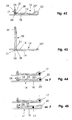
- Fig. 2 shows the compensation or edge end section 14 with the eyelet 22, bent back by a first leg 18 and a free one Leg 19 is limited.
- the leg 18 is part of the associated Wire 12.
- the leg 19 is parallel to that Leg 18 and on him. Both legs 18 and 19 are in the Plane of the wires 12 and on the perpendicular to them Wire 13.
- the end 21 of the leg 19 forms a securing part, which is attached to the leg 18 behind the cross wire 13.
- the Leg end 21 is wound helically around leg 18, that it points inwards away from the edge of the grid mat. In the embodiment is the end 21 about two to three times around Leg 18 wrapped and welded to it for a secure connection to ensure. This results in an optimal welding point, which corresponds to a cross wire welding point.
- the eyelet 22 has an approximately semicircularly curved first section 22 'and a second straight section 22 "which is in plan view 3 obliquely to at a small acute angle Leg 18 runs and merges into the free leg 19.
- the training differs from this embodiment according to 4 and 5 only in that the leg 19 with a lateral distance corresponding to the diameter of the wire 13 runs next to and above the leg 18.
- the cross wire 13 then lies on the leg 18 and is overlapped by the leg 19.
- this wire end section 14 is of identical design like the end section 14 according to FIGS. 2 and 3.
- the legs are 18, 19 in parallel on top of and on top of each other.
- the lower leg 18 lies on the cross wire 13.
- the leg end 21 of the free Leg 15 is in accordance with the previously described embodiments wrapped behind the cross wire 13 and also has from the edge of the mesh mat to the inside.
- the exemplary embodiment differs from this embodiment 8 and 9 only in that the cross wire 13, accordingly as in the embodiment of FIGS. 4 and 5, between the legs 18 and 19 that rest against him.
- FIGS. 12 and 13 corresponds to the embodiment 4 and 5, the leg end 21 corresponding the previously described embodiment before the cross wire 13 lies.
- the end section 14 according to FIGS. 14, 15 and 16, 17 corresponds the end portion of FIGS. 6, 7, the wound Leg end 21 lies in front of the cross wire 13.
- the cross wire 13 is on the underside of the longitudinal wire 12, in the exemplary embodiment according to FIGS. 16, 17 on the line wire.
- FIGS. 22 to 41 correspond essentially 2 to 21 with the difference, that instead of the wound leg end 21 a separate Securing part 23 is provided. With him, the Legs 18, 19 with each other or one of the legs with the cross wire 13 clamped connected.
- the securing part 23 is designed as a sleeve, which is preferably consists of metal and on the legs 18, 19 to be connected or the cross wire 13 is clamped.
- the securing part is located 23 behind the cross wire 13, while in the embodiments 30 to 37 lies in front of the cross wire 13.
- the 22 and 23 is the same as the embodiment 2 and 3 and has the side by side in the plane of the longitudinal wires 12 lying legs 18, 19 through the securing sleeve 23 are connected to each other behind the cross wire 13.
- the end section 14 according to FIGS. 24 and 25 corresponds to the embodiment 4 and 5.
- the upper leg 19 is behind the cross wire 13 bent so far down that its free end next to the leg 18 in the plane of the longitudinal wires 12. Thereby can the free end of the leg 19 and the leg 18 simply connect with the securing sleeve 23.
- the end section 14 of FIGS. 26 and 27 corresponds to the embodiment 6 and 7.
- the securing sleeve 23 is arranged upright and engages behind the cross wire 13 the free end of the Leg 19 and the leg 18, which lie on top of each other.
- FIGS. 28 and 29 corresponds essentially the embodiment of FIGS. 8 and 9 or 24 and 25.
- the free end of the leg 19 is so far behind the cross wire 13 bent down so that it rests on the leg 18.
- the standing Arranged securing sleeve 23 engages around the free end of the Leg 19 and leg 18.
- the end section 14 according to FIGS. 30 and 31 corresponds to the embodiment 10 and 11.
- the two legs 18 and 19 lie against each other in the plane of the longitudinal wires 12 and are connected to each other in front of the cross wire 13 by the securing sleeve 23.
- the end section according to FIGS. 32 and 33 corresponds to the exemplary embodiment 12 and 13 or 30 and 31.
- the cross wire 13 rests on the leg 18.
- the legs lie 18, 19 on top of each other and are through the standing locking sleeve 23 connected to each other.
- the leg 18 lies on the cross wire 13 on.
- the Leg 19 following the eyelet 22 above and parallel to Leg 18.
- the leg 19 is about the thickness of the leg 18 arranged offset on which the cross wire 13 lies.
- the straight leg 19 runs not inclined. Its free end 21 is bent at right angles so that it rests laterally on the cross wire 13. Grips around the securing sleeve 23 the free leg end 21 and the cross wire 13.
- the securing sleeve 23 is used in the described embodiments so applied that the free end of the leg 19 is not protrudes. This means there is no risk of injury or damage.
- the end sections 14 according to FIGS. 23 to 41 are like the end sections 14 according to FIGS. 2 to 21 designed so that a risk of injury due to protruding wire ends and a risk of corrosion is safely avoided. It is also an optimal weld created and thus ensured that the desired inclination the wall crown can be created. There can be inclinations up to at least 16% can be achieved.
- the legs 18, 19 are welded to the legs 26, 27.
- the Open wire ends of the end sections 14, 15 protrude inwards.
- a Tensile force F acts on the inclined leg 19 is deformed.
- the illustration shows the leg 19 in its maximum deformed position in which it is parallel and, in side view seen, lies above the leg 18. Because of the elastic Deformation of the leg 19, the end portion 14 is rotated, so that the tension without damage to the end portion 14th can be included.
- Fig. 45 shows the deformation of the leg 19 when over the closure part 17 a pressure force F acts on the eyelet 22.
- the closure part 17 presses the leg 19 elastically upwards and is in the Area moved between the legs 18 and 19.
- the Eyelet 22 expanded and the leg 19 raised so that it from the eyelet 22 is inclined downwards towards the end section 25. In this way, compressive forces (compressions) can be carried out without danger damage to the end section 14 is properly received become.
- the wire end sections 14 according to FIGS. 46 to 48 are designed such that they have an even greater stretch or compression flawlessly be able to record.
- at least one of the legs 18 has 19 a profile, such as a kink and / or a wavy one Bend 24 or the like.
- the end section 14 according to FIG. 46 is the one adjoining the eyelet 22 Leg 19 bent in a V-shape and extends from the eyelet 22 from down to the area below the leg 18. Due to the V-shaped design of the leg 19 is a larger deformation path when tensile and compressive forces occur.
- the leg 19 is wavy, in the exemplary embodiment with three shaft sections 24, profiled.
- the profile 24 is designed so that it up to the area above and below the leg 18 extends.
- the leg 18 is designed such that that it is in the area between the contact point of the cross wire 13 or its loop-shaped end section 15 and the eyelet 22 undulating.
- the section 22 "of the eyelet 22 extends slightly over the leg 18.
- the profiled design of the legs 18 and 19 can also in the Performance forms according to FIGS. 2 to 45 may be provided. It is further conceivable that both legs 18, 19 are profiled to even greater stretching or compression of the end sections To reach 14 or 15.
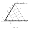
- FIGS. 49 shows a device 1 with which embankments are secured, whose visible areas are preferably greened.
- the facility consists of longitudinally and vertically connected, differently designed mesh mats 7, 8 and 10, 11. Im Such a device will follow with reference to FIGS. 49 to 53 described in more detail.
- the grid mats 7, 8 and 10, 11 are over eyelets 22 and connected by them connecting parts 40.
- the eyelets 22 are in accordance with the embodiments of FIGS. 2 to 48 with elastic deformable compensating sections 14, 15 provided to avoid occurring strains and compressions when using device 1 to record properly can.
- a front grid mat 8 On the bottom grid mat 10 is at the edge 30 (Fig. 51) a front grid mat 8 connected.
- the grid mats 10 and 8 are connected to one another by lattice mat 7 (FIGS. 49 and 53) and supported against each other. They are in the installed position Lattice mats 7 vertical. Over the length of the lattice mats 10 and 8 are such mesh mats 7 designed as support grids at a distance arranged from each other. Through the grid mats 7 is a spatial stable component created that with side by side and on top of each other same components to create an embankment can be connected.
- the grid mat 10 is crossed by each other Lattice bars or wires formed. They preferably have the same Distance from each other and cross each other at right angles, so that rectangular meshes 31 are formed.
- the grid mat 10 has illustrated embodiment rectangular shape. The two of them Narrow sides 32 and 33 and the ends forming a long side 30 the grid wires 12, 13 are bent into eyelets 22.
- the the Long side 30 opposite long side 34 of the lattice mat 10 is formed by end wire 13 on which the ends of the grid wires 13 lying at right angles thereto, preferably without Supernatant are attached. All or only one can be used for the eyelets 22 Part of them with the previously described elastically deformable Compensating sections 14, 15 (cf. FIGS. 2 to 48) may be provided.
- the grid mat 8 (Fig. 50) is again intersecting Rods and wires 12 and 13 formed, which are preferred to each other cut at right angles.
- the rods 12 and / or 13 preferably have equal distance from each other, so that rectangular, preferably square meshes 35 are formed.
- the grid mat 8 has Embodiment rectangular shape and same dimensions as that Lattice mat 10.
- the narrow sides 36, 37 and one long side 38 of the grid mat 8 forming ends of the grid rods or wires 12, 13 are bent into eyelets 22, which again correspond to the embodiments 2 to 48 may be formed.
- the the long side 38 opposite long side 39 is by the End-side lattice rod 13 is formed on which the eyelets 22 opposite Ends of the bars 12 are attached.
- these rods 12 can be attached to the end rod 13 be that they don't survive him. This will make one Risk of injury when handling and / or installing the front grille safely avoided. It is also possible, as Fig. 50 shows, that the ends of the rods 12 opposite the eyelets 22 slightly protrude beyond the end rod 13.
- the bars 12, 13 of the lattice mats 10 and 8 are at the crossing points firmly connected, preferably welded.
- the Bars 12, 13 are preferably made of metallic material, the gives the respective grid 10, 8 optimal strength.
- the grid mats but can also be made from plastic wires or rods his.
- the front grid mat 8 has a smaller one Mesh size than the bottom mesh panel 10.
- the mesh panels 8, 10 can also have the same mesh size.
- the grids 8, 10 are along their long sides 38, 30 with a Connecting rod 40 (Fig. 52) to a prefabricated unit with each other connected.
- the connecting rod 40 also consists of metallic material and is through the eyelets 22 of the grid 8, 10th plugged.
- the rod 40 is at one end bent into an eyelet 41, the diameter of which is larger than that Diameter of the eyelets 22 to ensure that the rod 40 is not can slip through the eyelets 22 with its eyelet end 41.
- Eyelet 22 attached, preferably welded.
- the connecting rod 41 is so long that it through all Eyelets 22 on the respective long sides 30, 38 of the lattice mats 10, 8 can be inserted.
- a fleece 42 (FIG. 49) is placed on the grid mat 8, preferably is a coconut fleece.
- the fleece 42 serves as protection against erosion the embankment and as a green base.
- This fleece layer 42 is at the upper end 43 on the projecting ends 44 (Fig. 50) Wires 12 inserted.
- the wires 12 are not over the ends Rod 13 of the grid mat 8, then the fleece 42 on his End 43, for example with brackets or the like Connecting parts are connected to the grid mat 7.
- the fleece 42 (not shown) Openings that in the installed position with the openings of the eyelets 22nd the grid mats 8, 10 are aligned.
- the rod 40 When pushing the rod 40 not only are the grids 10 and 8 articulated with one another connected, but also the lower end 45 of the fleece 42 firmly the grid mat 8. This means additional fasteners for the fleece 42 is not required.
- the fleece 42 is on the inside facing the lattice mat 10 the mesh mat 8 attached (Fig. 49).
- the pre-assembled unit from the grid mats 10 and 8 and the fleece 42 is stiffened at the construction site with the grid mat 7. It is formed by wires and with connecting rods on the bottom Mesh mat 10 and connected to the front mesh mat 8. 53 shows, the grid mat 7 has three mutually parallel Wires 13, 13 ', 13 ", each at both ends to form an eyelet 22 are bent.
- the rod 13 is the longest and the rod 13 "is the shortest.
- the parallel rods 13, 13 ', 13 "lying opposite one another are separated by two ends Rods 12, 12 'connected to each other with their ends these rods are attached.
- the wires 12, 12 'to 12 “' are preferably the same Distance from each other and perpendicular to the bars 13, 13 ', 13 ".
- the grid mat 7 is mirror-symmetrical to its longitudinal center plane educated.
- the length gradation of the wires 13, 13 ', 13 " is chosen so that the required slope angle ⁇ (Fig. 49) is reached becomes.
- the side mesh mats 7 can optimally pull and compressive forces transferred so that the device is not damaged.
- a reinforcement for example a grid can be. It extends over the grid mat 10 to the rear and is anchored in the ground.
- a next grid mat 10 can be placed thereon be articulated again with a grid mat 8 and a fleece 42 connected is. You can also use the 7 in are supported against each other in the manner described. To this In this way, the device is also extended in the height direction.
- the mesh mat 10 is possible to use to extend to the rear accordingly or another Lattice mat by means of a connecting rod 40 on the long side 34 to connect the grid mat 10 connected to the grid mat 8.
- the mesh mat 7 is also useful on the inside with the Fleece 42 provided so that on this end side of the device Greening can be made.
- the fleece 42 can except on its upper edge 43 and on its lower edge 45 also in the area between its edges with the Mesh mat 8 by additional fasteners, such as Brackets.
- the facility described 1 and the lattice mats 7 can side by side and on top of each other be placed until the desired length and height of the to be erected Embankment is reached.
- the fleece 42 can with respect to the subsequent greening in addition to coconut material from each other suitable material. Since the lattice mats 8, 10 and the fleece 42 is delivered to the installation site pre-assembled, simple installation of the device is possible because of the installation location only the grid mats 7 are to be attached to the unit. With Such an assembly is easy to carry out the rods 40.
- a grid mat on the bottom 10 attached a mesh mat 47, which is advantageously made of wire exists, but can also be formed by a plastic grid.
- the Lattice mat 47 is advantageous by crossing bars formed, which are firmly connected to each other at their crossing points are.
- Simply connect to the grid mat 47 around the grid mat 47 to be able to, is the long side of the mesh mat 47 with eyelets 22nd provided, which are formed by the protruding wire ends.
- she are corresponding to the eyelets according to FIGS. 2 to 48 with elastic deformable bent-back compensation sections.
- the grid mat 10 is also different from the embodiment 49 to 53, on the long side 34 (Fig. 51) with appropriate eyelets.
- the bars 12 of the grid mat 10 then project over the long side 34.
- the connecting rod 40 (FIG. 52) can be inserted into the lattice mats 10 and 47 become. In this way, the grid mat 10 can be easily extend.
- the grid mat 47 can be on the grid mat 10 opposite side with additional eyelets 22, so that also several mesh mats 47 can be hung together.
- the connection the grid mats 47 are again carried out via the connecting rods 40.
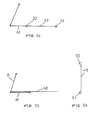
- the device 1 according to FIG. 54 has the same design like that according to FIGS. 49 to 53. In FIG. 54 is the clarity drawn in because of a side mesh mat.
- the grid mat 10 there is one on the grid mat 10 Lattice mat 48 placed, which extend from the lattice mat 8 can and survives over the grid mat 10.
- the grid mat 48 can be made of metallic material or plastic.
- the Lattice mat 48 can be attached to the lattice mat 10 in a suitable manner so that it cannot slip. Otherwise, the 55 may be the same design as that 49 to 53. In Fig. 55 is for clarity the side grid mat is not shown.
- the mesh mat 8 can be used individually Support rods 49 (Fig. 56) are supported on the grid mat 10.
- the support rod 49 is with hooks at both ends 50, 51 provided with which he hung in the lattice mats 8, 10 can be. Then the hooks 50, 50 with corresponding Tools deformed into eyelets so that the support rods 49 are held captive on the device 1.
- the support rods 49 are provided at the appropriate places in the facility and can therefore be of different lengths.
- the support bars 49 are advantageously made of metal, so that they are in use occurring forces can safely absorb. Since the support rods in installed in the same way as the mesh mat 7 at the installation site is a very simple adjustment to the required Slope or slope angles possible.
Abstract
Description
Die Erfindung betrifft eine Gittermatte, insbesondere für Gabionenkörbe,
nach dem Oberbegriff des Anspruches 1.The invention relates to a mesh mat, in particular for gabion baskets,
according to the preamble of
Es sind Gittermatten von Gabionen bekannt, bei denen die Enden der Längs- und Querdrähte zu einer Öse umgebogen sind. Durch diese Ösen werden Verbindungsstäbe gesteckt, um die einzelnen Matten und Gabionenkörbe miteinander zu verbinden. Durch Setzungen innerhalb der Gabionenkörbe kann es bei solchen Gittermatten zu einem Bruch der Schweißstellen dieser Ösen kommen, was wiederum zu einer Ausbauchung der Gabionenkörbe führen kann.Gabion meshes are known in which the ends of the Line and cross wires are bent into an eyelet. Through this Eyelets are attached to the individual mats and gabion baskets. By settling within the gabion baskets can become one with such mesh mats Broken welds of these eyelets come, which in turn can lead to bulging of the gabion baskets.
Der Erfindung liegt die Aufgabe zugrunde, Gittermatten der gattungsbildenden Art so auszubilden, daß bei konstruktiv einfacher Ausbildung im Bereich der Ösen Dehnungen und Stauchungen einwandfrei aufgenommen werden können.The invention has for its object grid mesh of the generic Type in such a way that with simple construction in the area of the eyelets, stretching and compression perfectly can be included.
Diese Aufgabe wird bei einer Gittermatte der gattungsbildenden Art
erfindungsgemäß mit den kennzeichnenden Merkmalen des Anspruches
1 gelöst.This task is carried out with a lattice mat of the generic type
according to the invention with the characterizing features of the
Infolge der erfindungsgemäßen Ausbildung schließt an die Öse ein Ausgleichsabschnitt an, von dem Stauchungen oder Biegungen, die während des Gebrauchs der Gabionenkörbe auf die Ösen wirken, einwandfrei aufgenommen werden können. Für den Aufbau von Gabionenkörben, beispielsweise für Böschungssicherungen mit einer schrägen Mauerkrone, können die Ösen an der Verbindungsstelle infolge des Aufweitabschnittes leicht geweitet werden und so eine Schräglage der Mauerkrone auf einfache Weise erzeugt werden. Durch die erfindungsgemäße Ausbildung wird ferner eine optimale Schweißstelle erreicht, die eine reine Kreuzdrahtschweißung ist, so daß die Gefahr eines Bruches der Schweißstelle sicher vermieden ist. Eine Korrosionsgefahr durch Beschädigung der Schweißstelle ist damit ebenfalls vermieden. Außerdem liegt die Schweißstelle entfernt von der Öse, so daß der Korrosionsangriff, der bei den bekannten Gittermatten zuerst an der Schweißstelle der Öse stattfand, dort jetzt völlig ausgeschlossen ist. Mit der erfindungsgemäßen Gittermatte können beispielsweise Dehnwege von etwa 3,5 mm und mehr erreicht werden, ohne daß in den Drähten Spannungen aufgebaut werden, die zu einem Bruch des Drahtes führen können. Vorteilhaft ist ferner, daß durch die erfindungsgemäße Ausbildung der Vorteil der Gabionenbauweise, bei der Bewegungen im Bauwerk aufgenommen werden können, noch verstärkt wird. Je nach Ausbildung des Ausgleichs bzw. Verformungsabschnittes der Gittermatte können mehr oder weniger große Dehnungs- bzw. Stauchungswege erreicht werden.As a result of the training according to the invention includes the eyelet Compensating section, from the upsets or bends that act on the eyelets while using the gabion baskets, can be recorded properly. For the construction of gabion baskets, for example for slope protection with a sloping wall crown, the eyelets at the junction can be easily expanded due to the expansion section and so one Oblique position of the wall crown can be generated in a simple manner. The training according to the invention also makes an optimal one Welding point reached, which is a pure cross wire welding, so that the risk of breakage of the weld is surely avoided is. There is a risk of corrosion from damage to the weld thus also avoided. The weld is also removed from the eyelet, so that the corrosion attack, which in the known Lattice mats first took place at the welding point of the eyelet, there now is completely excluded. With the grid mat according to the invention For example, expansion paths of about 3.5 mm and more can be achieved without tension building up in the wires, that can break the wire. It is advantageous further that the advantage of the training according to the invention Gabion construction, in which movements in the building are recorded can be reinforced. Depending on the training of the compensation or deformation section of the grid mat can do more or less large expansion or compression paths can be achieved.
Weitere Merkmale der Erfindung ergeben sich aus den weiteren Ansprüchen, der Beschreibung und den Zeichnungen.Further features of the invention result from the further claims, the description and the drawings.
Die Erfindung wird nachstehend anhand mehrerer in den Zeichnungen dargestellter Ausführungsbeispiele näher beschrieben. Es zeigt:
- Fig. 1
- einen Teil einer Stützwand mit mehreren neben- und übereinander angeordneten Gabionenkörben mit erfindungsgemäßen Gittermatten in Seitenansicht,
- Fig.2
- einen Drahtendabschnitt einer erfindungsgemäßen Gittermatte in Seitenansicht,
- Fig. 3
- den Endabschnitt gemäß Fig. 2 in Draufsicht,
- Fig. 4 bis 42
- jeweils eine weitere Darstellung eines erfindungsgemäßen Drahtendabschnittes in Darstellungen entsprechend den Fig. 2 und 3,
- Fig. 43
- eine Darstellung entsprechend Fig. 2 und 3, bzw. 42, jedoch als Draufsicht an der Ecke einer Gittermatte,
- Fig. 44
- den Drahtendabschnitt gemäß Fig. 42 in gedehnter Stellung,
- Fig. 45
- den Drahtendabschnitt gemäß Fig. 42 in gestauchter Lage,
- Fig. 46 bis 48
- jeweils eine weitere Ausführungsform eines erfindungsgemäßen Drahtendabschnittes in Darstellungen entsprechend Fig. 2.
- Fig. 49
- im Querschnitt einen Teil einer Einrichtung zum Erstellen begrünbarer Böschungen,
- Fig. 50
- eine Draufsicht auf eine frontseitige Gittermatte der Einrichtung gemäß Fig. 49,
- Fig. 51
- eine Draufsicht auf eine bodenseitige Gittermatte der Einrichtung gemäß Fig. 49,
- Fig. 52
- einen Verbindungsstab, mit dem die Gittermatten gemäß den Fig. 50 und 51 miteinander verbunden werden können,
- Fig. 53
- eine Draufsicht auf ein Stützgitter der Einrichtung gemäß Fig. 49,
- Fig. 54 und 55
- in schematischer Darstellung zwei weitere Ausführungsformen von Einrichtungen zum Erstellen begrünbarer Einrichtungen,
- Fig. 56
- eine weitere Ausführungsform eines Stützteiles.
- Fig. 1
- part of a retaining wall with a plurality of gabion baskets arranged side by side and one above the other with lattice mats according to the invention in side view,
- Fig.2
- a wire end portion of a lattice mat according to the invention in side view,
- Fig. 3
- 2 in top view,
- 4 to 42
- in each case a further representation of a wire end section according to the invention in representations corresponding to FIGS. 2 and 3,
- Fig. 43
- 2 and 3, or 42, but as a plan view at the corner of a grid mat,
- Fig. 44
- 42 in the stretched position,
- Fig. 45
- 42 in the upset position,
- 46 to 48
- in each case a further embodiment of a wire end section according to the invention in representations corresponding to FIG. 2.
- Fig. 49
- in cross-section part of a facility for creating greenable embankments,
- Fig. 50
- 4 shows a plan view of a grid mat on the front of the device according to FIG. 49,
- Fig. 51
- 4 shows a plan view of a grid mat on the bottom of the device according to FIG. 49,
- Fig. 52
- a connecting rod with which the grid mats according to FIGS. 50 and 51 can be connected to each other,
- Fig. 53
- 4 shows a plan view of a support grid of the device according to FIG. 49,
- 54 and 55
- a schematic representation of two further embodiments of facilities for creating greenable facilities,
- Fig. 56
- a further embodiment of a support part.
Die in Fig. 1 dargestellte Einrichtung dient beispielsweise als Böschungssicherung.
Sie besteht aus einer Vielzahl von miteinander
verbundenen, im wesentlichen gleichen Drahtkörben 1 bis 6, sogenannten
Gabionen. Sie sind mit (nicht dargestelltem) Füllmaterial,
wie beispielsweise Steinen und/oder Erde und/oder Pflanzen
und/oder Isolier- und/oder Lärmschutzstoffen, gefüllt. Die Gabionen 1
bis 6 bestehen aus Gittermatten, von denen in Fig. 1 nur jeweils eine
Gittermatte dargestellt ist. Wie anhand der Gabione 1 erläutert werden
soll, haben die seitlichen Gittermatten 7 Trapezform, während
die stirnseitigen Gittermatten 8, 9 und die boden- und deckenseitigen
Gittermatten 10 und 11 rechteckigen oder quadratischen Umriß haben.
Durch die trapezförmig ausgebildeten seitlichen Gittermatten 7
wird erreicht, daß die mauerartige Böschungssicherung die gewünschte
schräge Mauerkrone aufweist.The device shown in Fig. 1 serves, for example, as slope protection.
It consists of a large number of each other
connected, essentially the
Die Gittermatten 7 bis 11 bestehen jeweils aus einander kreuzenden
Längs- und Querdrähten 12 und 13, die in den Kreuzungsstellen vorzugsweise
miteinander verschweißt sind. Zum Verbinden der Gittermatten
7 bis 11 sowie der Gabionen 1 bis 6 miteinander sind zumindest
einige der Endabschnitte 14, 15 der Drähte 12, 13 als elastisch
verformbare Ausgleichsabschnitte ausgebildet. Die Endabschnitte 14,
15 sind ösen- bzw. schlaufenartig ausgebildet, so daß am Rand der
Gittermatte 7 eine Einhänge- bzw. Durchstecköse 22 gebildet ist. In
die miteinander fluchtenden Ösen 22 der Endabschnitte 14, 15 werden
stabartig ausgebildete Verschlußteile 16, 17 gesteckt. Nicht alle
Drähte 12, 13 müssen die endseitigen Ausgleichsabschnitte 14, 15
aufweisen. Es können selbstverständlich auch nur einige oder nur die
in den Eckbereichen der Gittermatten 7 bis 11 liegenden Drähte Ausgleichsabschnitte
aufweisen.The
Um beim Einbau der Gabionen 1 bis 6 die schräge Mauerkrone zu
schaffen, müssen die Drahtendabschnitte 14, 15 bzw. ihre Ösen 22
gedehnt bzw. gestaucht werden, was durch die nachfolgend anhand
der Fig. 2 bis 48 beschriebene verformbare Ausbildung der Drahtendabschnitte
14, 15 gewährleistet ist.To close the sloping wall crown when installing
In den Fig. 2 bis 48 sind jeweils unterschiedliche Ausbildungen von
Endabschnitten 14, 15 der Gitterdrähte 12, 13 einer Gittermatte dargestellt.2 to 48 are different designs of
Fig. 2 zeigt den Ausgleichs- bzw. Randendabschnitt 14 mit der Öse
22, die von einem ersten Schenkel 18 und einem freien zurückgebogenen
Schenkel 19 begrenzt ist. Der Schenkel 18 ist Teil des zugehörigen
Drahtes 12. Der Schenkel 19 liegt parallel neben dem
Schenkel 18 und an ihm an. Beide Schenkel 18 und 19 liegen in der
Ebene der Drähte 12 und auf dem senkrecht zu ihnen verlaufenden
Draht 13. Das Ende 21 des Schenkels 19 bildet ein Sicherungsteil,
das hinter dem Querdraht 13 am Schenkel 18 befestigt ist. Das
Schenkelende 21 ist wendelförmig so um den Schenkel 18 geschlungen,
daß es vom Rand der Gittermatte weg nach innen weist. Im Ausführungsbeispiel
ist das Ende 21 etwa zwei- bis dreimal um den
Schenkel 18 gewickelt und an ihm verschweißt, um eine sichere Verbindung
zu gewährleisten. Hierbei ergibt sich eine optimale Schweißstelle,
die einer Kreuzdrahtschweißstelle entspricht. Diese Ausbildung
des Drahtendabschnittes 14 ermöglicht eine Dehnung in Drahtlängsrichtung,
ohne daß dabei im Draht 12 Spannungen aufgebaut
werden, die zu einem Bruch des Drahtes führen könnten. Der Vorteil
der flexiblen Gabionenbauweise, bei der Bewegungen im Bauwerk
aufgenommen werden können, wird durch die beschriebene flexible
Ausbildung der Endabschnitte 14 des Gitterdrahtes 12 noch verstärkt.
Die Öse 22 hat einen etwa halbkreisförmig gekrümmten ersten Abschnitt
22' und einen zweiten geraden Abschnitt 22", der in Draufsicht
gemäß Fig. 3 unter einem kleinen spitzen Winkel schräg zum
Schenkel 18 verläuft und in den freien Schenkel 19 übergeht.Fig. 2 shows the compensation or
Von dieser Ausführungsform unterscheidet sich die Ausbildung gemäß
den Fig. 4 und 5 nur dadurch, daß der Schenkel 19 mit einem
dem Durchmesser des Drahtes 13 entsprechenden Abstand seitlich
neben und oberhalb des Schenkels 18 verläuft. Der Querdraht 13
liegt dann auf dem Schenkel 18 und wird vom Schenkel 19 übergriffen.
Im übrigen ist dieser Drahtendabschnitt 14 gleich ausgebildet
wie der Endabschnitt 14 gemäß den Fig. 2 und 3.The training differs from this embodiment according to
4 and 5 only in that the
Bei der Ausführungsform nach den Fig. 6 und 7 liegen die Schenkel
18, 19 parallel übereinander und aufeinander. Der untere Schenkel
18 liegt auf dem Querdraht 13 auf. Das Schenkelende 21 des freien
Schenkels 15 ist entsprechend den zuvor beschriebenen Ausführungsformen
hinter dem Querdraht 13 gewickelt und weist ebenfalls
vom Rand der Gittermatte nach innen.In the embodiment according to FIGS. 6 and 7, the legs are
18, 19 in parallel on top of and on top of each other. The
Von dieser Ausführungsform unterscheidet sich das Ausführungsbeispiel
nach den Fig. 8 und 9 nur dadurch, daß der Querdraht 13, entsprechend
wie bei der Ausführungsform nach den Fig. 4 und 5, zwischen
den Schenkeln 18 und 19 verläuft, die an ihm anliegen.The exemplary embodiment differs from this
Beim Endabschnitt 14 gemäß den Fig. 10 und 11 liegt das gewickelte
Schenkelende 21 vor dem Querdraht 13, der unterhalb des Schenkels
18 liegt. Im übrigen entspricht diese Ausführungsform dem Ausführungsbeispiel
nach den Fig. 2 und 3. At the
Die Ausführungsform nach den Fig. 12 und 13 entspricht der Ausführungsform
nach den Fig. 4 und 5, wobei das Schenkelende 21 entsprechend
der zuvor beschriebenen Ausführungsform vor dem Querdraht
13 liegt.The embodiment according to FIGS. 12 and 13 corresponds to the
Der Endabschnitt 14 gemäß den Fig. 14, 15 und 16, 17 entspricht
dem Endabschnitt nach den Fig. 6, 7, wobei das gewickelte
Schenkelende 21 vor dem Querdraht 13 liegt. Bei der Ausführungsform
nach den Fig. 14, 15 liegt der Querdraht 13 an der Unterseite
des Längsdrahtes 12, beim Ausführungsbeispiel gemäß Fig. 16, 17
auf dem Längsdraht.The
Bei der Ausführungsform nach den Fig. 18, 19 und 20, 21 ist das
Schenkelende 21 um den unter bzw. auf dem Schenkel 18 liegenden
Querdraht 13 gewickelt, so daß es seitlich über den Schenkel 19 zur
Matteninnenseite ragt. Im übrigen ist der Endabschnitt 14 der Ausführungsform
nach den Fig. 18 und 19 gleich ausgebildet wie das Ausführungsbeispiel
gemäß den Fig. 2 und 3. Beim Endabschnitt 14 der
Ausführungsform nach den Fig. 20, 21 verläuft der Schenkel 19 von
der Öse 22 bis zum gewickelten Schenkelende 21 ansteigend, so
daß er mit zunehmendem Abstand von der Öse 22 zunehmenden Abstand
vom Schenkel 18 hat.In the embodiment according to FIGS. 18, 19 and 20, 21 that is
Die Ausführungsformen nach den Fig. 22 bis 41 entsprechen im wesentlichen
den Ausführungsformen gemäß Fig. 2 bis 21 mit dem Unterschied,
daß anstelle des gewickelten Schenkelendes 21 ein gesondertes
Sicherungsteil 23 vorgesehen ist. Mit ihm werden die
Schenkel 18, 19 miteinander bzw. einer der Schenkel mit dem Querdraht
13 klemmend verbunden.The embodiments according to FIGS. 22 to 41 correspond essentially
2 to 21 with the difference,
that instead of the wound leg end 21 a
Das Sicherungsteil 23 ist als Hülse ausgebildet, die vorzugsweise
aus Metall besteht und auf die die zu verbindenden Schenkel 18, 19
bzw. den Querdraht 13 geklemmt wird. The securing
Bei den Endabschnitten 14 gemäß den Fig. 22 bis 29 liegt das Sicherungsteil
23 hinter dem Querdraht 13, während es bei den Ausführungsformen
nach den Fig. 30 bis 37 vor dem Querdraht 13 liegt. Der
Endabschnitt 14 der Fig. 22 uns 23 ist gleich wie die Ausführungsform
nach den Fig. 2 und 3 und hat die nebeneinander in der Ebene
der Längsdrähte 12 liegenden Schenkel 18, 19, die durch die Sicherungshülse
23 hinter dem Querdraht 13 miteinander verbunden sind.22 to 29, the securing part is located
23 behind the
Der Endabschnitt 14 gemäß den Fig. 24 und 25 entspricht der Ausführungsform
nach den Fig. 4 und 5. Der obere Schenkel 19 ist hinter
dem Querdraht 13 so weit nach unten gebogen, daß sein freies Ende
neben dem Schenkel 18 in der Ebene der Längsdrähte 12 liegt. Dadurch
lassen sich das freie Ende des Schenkels 19 und der Schenkel
18 mit der Sicherungshülse 23 einfach miteinander verbinden.The
Der Endabschnitt 14 der Fig. 26 und 27 entspricht der Ausführungsform
nach den Fig. 6 und 7. Die Sicherungshülse 23 ist stehend angeordnet
und umgreift hinter dem Querdraht 13 das freie Ende des
Schenkels 19 und den Schenkel 18, die aufeinander liegen.The
Die Ausführungsform nach den Fig. 28 und 29 entspricht im wesentlichen
dem Ausführungsbeispiel nach den Fig. 8 und 9 bzw. 24 und 25.
Das freie Ende des Schenkels 19 ist hinter dem Querdraht 13 so weit
nach unten gebogen, dass er auf dem Schenkel 18 aufliegt. Die stehend
angeordnete Sicherungshülse 23 umgreift das freie Ende des
Schenkels 19 und den Schenkel 18.The embodiment according to FIGS. 28 and 29 corresponds essentially
the embodiment of FIGS. 8 and 9 or 24 and 25.
The free end of the
Der Endabschnitt 14 gemäß den Fig. 30 und 31 entspricht der Ausführungsform
nach den Fig. 10 und 11. Die beiden Schenkel 18 und
19 liegen in der Ebene der Längsdrähte 12 aneinander und werden
vor dem Querdraht 13 durch die Sicherungshülse 23 miteinander verbunden. The
Der Endabschnitt gemäß den Fig. 32 und 33 entspricht dem Ausführungsbeispiel
nach den Fig. 12 und 13 bzw. 30 und 31. Der Querdraht
13 liegt auf dem Schenkel 18 auf.The end section according to FIGS. 32 and 33 corresponds to the
Bei der Ausführungsform nach den Fig. 34 und 35 liegen die Schenkel
18, 19 aufeinander und sind durch die stehende Sicherungshülse
23 miteinander verbunden. Der Schenkel 18 liegt auf dem Querdraht
13 auf.In the embodiment according to FIGS. 34 and 35, the legs lie
18, 19 on top of each other and are through the
Beim Ausführungsbeispiel nach den Fig. 36 und 37, das der Ausführungsform
nach den Fig. 34 und 35 entspricht, liegt der Querdraht 13
auf dem Schenkel 18 auf.36 and 37, that of the
Die Fig. 38 und 39 zeigen eine Ausführungsform, bei der der Schenkel
19 von der Öse 22 aus nach unten geneigt verläuft. In Höhe des
Querdrahtes 13, auf dem der Schenkel 18 aufliegt, ist das freie Ende
21 des Schenkels 19 so rechtwinklig abgebogen, dass es seitlich am
Querdraht 13 anliegt. Die Sicherungshülse 23 umgreift das freie
Schenkelende 21 und den Querdraht 13.38 and 39 show an embodiment in which the
Beim Ausführungsbeispiel nach den Fig. 40 und 41 verläuft der
Schenkel 19 im Anschluß an die Öse 22 oberhalb und parallel zum
Schenkel 18. Dabei ist der Schenkel 19 um die Dicke des Schenkels
18 versetzt angeordnet, auf dem der Querdraht 13 liegt. Im Gegensatz
zur vorigen Ausführungsform verläuft der gerade Schenkel 19
nicht geneigt. Sein freies Ende 21 ist rechtwinklig so abgebogen, daß
es seitlich am Querdraht 13 anliegt. Die Sicherungshülse 23 umgreift
das freie Schenkelende 21 und den Querdraht 13.In the embodiment according to FIGS. 40 and 41, the
Die Sicherungshülse 23 wird bei den beschriebenen Ausführungsformen
so aufgebracht, dass das freie Ende des Schenkels 19 nicht
vorsteht. Dadurch besteht keine Verletzungs- und Beschädigungsgefahr.The securing
Die Endabschnitte 14 nach den Fig. 23 bis 41 sind wie die Endabschnitte
14 gemäß den Fig. 2 bis 21 so ausgebildet, daß eine Verletzungsgefahr
durch überstehende Drahtenden sowie eine Korrosionsgefahr
sicher vermieden wird. Es ist auch eine optimale Schweißstelle
geschaffen und damit sichergestellt, daß die gewünschte Neigung
der Mauerkrone erzeugt werden kann. Es können Neigungen bis zu
mindestens 16 % erreicht werden.The
Die Fig. 42 und 43 zeigen einen Endabschnitt 14, der mit einem
gleich ausgebildeten Endabschnitt 15 des Querdrahtes 13 so verbunden
wird, daß die Schenkel 26, 27 des Endabschnittes 25 zwischen
die Schenkel 18, 19 des Endabschnittes 14 ragen. Die Schenkel 18,
19 liegen auf den Schenkeln 26, 27 auf. Das freie Ende 28 des
Schenkels 27 ist so abgewinkelt, daß es seitlich am Schenkel 26 anliegt.
Der gerade Schenkel 27 ist von der Öse 29 aus nach unten geneigt.
Die Schenkel 26, 27 liegen parallel zueinander. Der obere
Schenkel 27 ist um die Dicke des unteren Schenkels 26 seitlich versetzt.
Die Schenkel 26, 27 liegen senkrecht zu den Schenkeln 18, 19.
Von der Öse 22 aus ist der gerade Schenkel 19 aufwärts geneigt. Der
gerade Abschnitt 22" der Öse 22 ist so weit heruntergezogen, daß er
in Seitenansicht gemäß Fig. 42 den Schenkel 18 übergreift. Die Öse
22 ist dadurch vollständig geschlossen.42 and 43 show an
Die Schenkel 18, 19 sind mit den Schenkeln 26, 27 verschweißt. Die
offenen Drahtenden der Endabschnitte 14, 15 ragen nach innen.The
Fig. 44 zeigt in der oberen Abbildung einen belastungsfreien Zustand
des Endabschnittes 14, durch dessen Öse 22 ein stabförmiges Verschlußteil
17 gesteckt ist. 44 shows a stress-free state in the upper figure
of the
In der unteren Abbildung der Fig. 44 ist der Fall dargestellt, daß auf
den Endabschnitt 14 bzw. die Öse 22 über das Verschlußteil 17 eine
Zugkraft F wirkt. Sie bewirkt, daß auf der geneigte Schenkel 19 elastisch
verformt wird. Die Abbildung zeigt den Schenkel 19 in seiner
maximale verformten Lage, in der er parallel und, in Seitenansicht
gesehen, oberhalb des Schenkels 18 liegt. Aufgrund der elastischen
Verformung des Schenkels 19 wird der Endabschnitt 14 gedreht, so
daß die Zugspannung ohne Beschädigung des Endabschnittes 14
aufgenommen werden kann.In the lower figure of Fig. 44 the case is shown that on
the
Fig. 45 zeigt die Verformung des Schenkels 19, wenn über das Verschlußteil
17 auf die Öse 22 eine Druckkraft F wirkt. Das Verschlußteil
17 drückt den Schenkel 19 elastisch nach oben und wird in den
Bereich zwischen die Schenkel 18 und 19 verschoben. Dabei wird die
Öse 22 aufgeweitet und der Schenkel 19 so angehoben, daß er von
der Öse 22 zum Endabschnitt 25 schräg nach unten geneigt verläuft.
Auf diese Weise können auch Druckkräfte (Stauchungen) ohne Gefahr
einer Beschädigung des Endabschnittes 14 einwandfrei aufgenommen
werden.Fig. 45 shows the deformation of the
Bei sämtlichen beschriebenen und noch zu beschreibenden Ausführungsformen werden die Zug- und Druckkräfte in gleicher Weise aufgenommen, wie anhand der Fig. 44 und 45 erläutert worden ist.In all the embodiments described and still to be described the tensile and compressive forces are absorbed in the same way, as has been explained with reference to FIGS. 44 and 45.
Die Drahtendabschnitte 14 nach den Fig. 46 bis 48 sind so ausgebildet,
daß sie eine noch größere Dehnung oder Stauchung einwandfrei
aufnehmen können. Hierzu weist mindestens einer der Schenkel 18,
19 eine Profilierung, wie einen Knick und/oder eine wellenförmige
Biegung 24 oder dgl. auf.The
Beim Endabschnitt 14 nach Fig. 46 ist der an die Öse 22 anschließende
Schenkel 19 V-förmig gebogen und erstreckt sich von der Öse
22 aus bis in den Bereich unterhalb des Schenkels 18. Aufgrund der
v-förmigen Ausbildung des Schenkels 19 steht ein größerer Verformungsweg
beim Auftreten von Zug- und Druckkräften zur Verfügung.The
Bei der Ausführungsform nach Fig. 47 ist der Schenkel 19 wellenförmig,
im Ausführungsbeispiel mit drei Wellenabschnitten 24, profiliert.
Selbstverständlich kann auch jede andere Profilierung mit mehr oder
weniger starker Wellung oder einer anderen Profilausbildung vorgesehen
werden. Die Profilierung 24 ist so ausgebildet, daß sie bis in
den Bereich oberhalb und unterhalb des Schenkels 18 reicht.In the embodiment according to FIG. 47, the
Beim Endabschnitt 14 nach Fig. 48 ist der Schenkel 18 so ausgebildet,
daß er im Bereich zwischen der Auflagestelle des Querdrahtes
13 bzw. seines schlaufenförmigen Endabschnittes 15 und der Öse 22
wellenförmig verläuft. Der Abschnitt 22" der Öse 22 reicht geringfügig
über den Schenkel 18.In the
Die profilierte Ausbildung der Schenkel 18 bzw. 19 kann auch bei den
Aufführungsformen gemäß den Fig. 2 bis 45 vorgesehen sein. Es ist
ferner denkbar, daß auch beide Schenkel 18, 19 profiliert ausgebildet
sind, um eine noch größere Dehnung oder Stauchung der Endabschnitte
14 oder 15 zu erreichen.The profiled design of the
Fig. 49 zeigt eine Einrichtung 1, mit der Böschungen gesichert werden,
deren Sichtflächen vorzugsweise begrünt werden. Die Einrichtung
besteht aus in Längs- und Höhenrichtung miteinander verbundenen,
verschieden ausgebildeten Gittermatten 7, 8 und 10, 11. Im
folgenden wird anhand der Fig. 49 bis 53 eine derartige Einrichtung
näher beschrieben. Die Gittermatten 7, 8 und 10, 11 sind über Ösen
22 und durch sie gesteckte Verbindungsteile 40 miteinander verbunden.
Die Ösen 22 sind gemäß den Ausführungsformen nach den Fig.
2 bis 48 mit elastischer verformbar ausgebildeten Ausgleichsabschnitten
14, 15 versehen, um auftretende Dehnungen und Stauchungen
bei Gebrauch der Einrichtung 1 einwandfrei aufnehmen zu
können.49 shows a
An der bodenseitigen Gittermatte 10 ist an deren Rand 30 (Fig. 51)
eine frontseitige Gittermatte 8 angeschlossen. Die Gittermatten 10
und 8 werden durch Gittermatien 7 (Fig. 49 und 53) miteinander verbunden
und gegeneinander abgestützt. In der Einbaulage stehen die
Gittermatten 7 senkrecht. Über die Länge der Gittermatten 10 und 8
sind solche als Stützgitter ausgebildete Gittermatten 7 mit Abstand
voneinander angeordnet. Durch die Gittermatten 7 wird ein räumlich
stabiles Bauelement geschaffen, das mit nebeneinander und übereinander
liegenden gleichen Bauelementen zur Erstellung einer Böschung
verbunden werden kann.On the
Wie Fig. 51 zeigt, wird die Gittermatte 10 durch einander kreuzende
Gitterstäbe bzw. -drähte gebildet. Sie haben vorzugsweise gleichen
Abstand voneinander und kreuzen einander rechtwinklig, so daß
rechteckige Maschen 31 gebildet werden. Die Gittermatte 10 hat im
dargestellten Ausführungsbeispiel Rechteckform. Die die beiden
Schmalseiten 32 und 33 sowie die eine Längsseite 30 bildenden Enden
der Gitterdrähte 12, 13 sind zu Ösen 22 gebogen. Die der
Längsseite 30 gegenüberliegende Längsseite 34 der Gittermatte 10
wird durch endseitigen Gitterdraht 13 gebildet, an dem die Enden der
rechtwinklig dazu liegenden Gitterdrähte 13 vorzugsweise ohne
Überstand befestigt sind. Für die Ösen 22 können alle oder nur ein
Teil von ihnen mit den zuvor beschriebenen elastisch verformbaren
Ausgleichsabschnitten 14, 15 (vgl. die Fig. 2 bis 48) versehen sein.51 shows, the
Die Gittermatte 8 (Fig. 50) wird wieder durch einander kreuzende
Stäbe und Drähte 12 und 13 gebildet, die einander vorzugsweise
rechtwinklig schneiden. Die Stäbe 12 und/oder 13 haben vorzugsweise
gleichen Abstand voneinander, so daß rechteckige, vorzugsweise
quadratische Maschen 35 gebildet werden. Die Gittermatte 8 hat im
Ausführungsbeispiel Rechteckform und gleiche Abmessungen wie die
Gittermatte 10. Die die Schmalseiten 36, 37 und die eine Längsseite
38 der Gittermatte 8 bildenden Enden der Gitterstäbe bzw. -drähte
12, 13 sind zu Ösen 22 gebogen, die wieder entsprechend den Ausführungsformen
nach den Fig. 2 bis 48 ausgebildet sein können. Die
der Längsseite 38 gegenüberliegende Längsseite 39 wird durch den
endseitigen Gitterstab 13 gebildet, an dem die den Ösen 22 gegenüberliegenden
Enden der Gitterstäbe 12 befestigt sind. Wie bei der
Gittermatte 10 können diese Stäbe 12 so am endseitigen Stab 13 befestigt
sein, daß sie nicht über ihn überstehen. Dadurch wird eine
Verletzungsgefahr bei der Handhabung und/oder Montage des Frontgitters
sicher vermieden. Es ist auch möglich, wie Fig. 50 zeigt, daß
die den Ösen 22 gegenüberliegenden Enden der Stäbe 12 geringfügig
über den endseitigen Stab 13 ragen.The grid mat 8 (Fig. 50) is again intersecting
Rods and
Die Stäbe 12, 13 der Gittermatten 10 und 8 sind an den Kreuzungspunkten
fest miteinander verbunden, vorzugsweise verschweißt. Die
Stäbe 12, 13 bestehen vorzugsweise aus metallischem Werkstoff, der
dem jeweiligen Gitter 10, 8 eine optimale Festigkeit gibt. Die Gittermatten
können aber auch aus Kunststoffdrähten bzw. -stäben gefertigt
sein.The
Im Ausführungsbeispiel hat die frontseitige Gittermatte 8 eine kleinere
Maschenweite als die bodenseitige Gittermatte 10. Die Gittermatten
8, 10 können aber auch gleiche Maschenweite haben.In the exemplary embodiment, the
Die Gitter 8, 10 werden längs ihrer Längsseiten 38, 30 mit einem
Verbindungsstab 40 (Fig. 52) zu einer vorgefertigten Baueinheit miteinander
verbunden. Der Verbindungsstab 40 besteht ebenfalls aus
metallischem Werkstoff und wird durch die Ösen 22 der Gitter 8, 10
gesteckt. Dadurch sind die beiden Gitter an ihren Längsseiten 30, 38
schwenkbar miteinander verbunden. Der Stab 40 ist an einem Ende
zu einer Öse 41 gebogen, deren Durchmesser größer ist als der
Durchmesser der Ösen 22, um sicherzustellen, daß der Stab 40 nicht
mit seinem Ösenende 41 durch die Ösen 22 rutschen kann. Vorteilhaft
wird das andere Ende des Verbindungsstabes 41 nach dem
Durchstecken durch die Ösen 22 an der in Durchsteckrichtung letzten
Öse 22 befestigt, vorzugsweise verschweißt. Dadurch ist der Verbindungsstab
41 unlösbar mit den beiden Gittern 8, 10 verbunden, die
dadurch auch nicht mehr unbeabsichtigt voneinander gelöst werden
können. Der Verbindungsstab 41 ist so lang, daß er durch sämtliche
Ösen 22 an der jeweiligen Längsseite 30, 38 der Gittermatten 10, 8
gesteckt werden kann. Vor der Verbindung der Gittermatten 10 und 8
wird auf die Gittermatte 8 ein Vlies 42 (Fig. 49) gelegt, das vorzugsweise
ein Kokosvlies ist. Das Vlies 42 dient als Erosionsschutz für
die Böschung und als Begrünungsbasis. Diese Vliesschicht 42 wird
am oberen Ende 43 auf die überstehenden Enden 44 (Fig. 50) der
Drähte 12 gesteckt. Stehen die Drähte 12 nicht über den endseitigen
Stab 13 der Gittermatte 8 über, dann kann das Vlies 42 an seinem
Ende 43 beispielsweise mit Klammern oder ähnlichen
Verbindungsteilen mit der Gittermatte 7 verbunden werden.The
Am unteren Ende 45 (Fig. 49) weist das Vlies 42 (nicht dargestellte)
Öffnungen auf, die in der Einbaulage mit den Öffnungen der Ösen 22
der Gittermatten 8, 10 fluchten. Beim Durchstecken des Stabes 40
werden dadurch nicht nur die Gitter 10 und 8 gelenkig miteinander
verbunden, sondern auch das untere Ende 45 des Vlieses 42 fest mit
der Gittermatte 8. Dadurch sind zusätzliche Befestigungsmittel für
das Vlies 42 nicht erforderlich.At the lower end 45 (FIG. 49), the fleece 42 (not shown)
Openings that in the installed position with the openings of the eyelets 22nd
the
Das Vlies 42 wird an der der Gittermatte 10 zugewandten Innenseite
der Gittermatte 8 befestigt (Fig. 49).The
Die so vormontierte Baueinheit aus den Gittermatten 10 und 8 und
dem Vlies 42 wird an der Baustelle mit der Gittermatte 7 versteift. Es
wird durch Drähte gebildet und mit Verbindungsstäben der bodenseitigen
Gittermatte 10 als auch mit der frontseitigen Gittermatte 8 verbunden.
Wie Fig. 53 zeigt, hat die Gittermatte 7 drei zueinander parallele
Drähte 13, 13', 13", die an beiden Enden jeweils zu einer Öse
22 gebogen sind. Die Stäbe 13, 13', 13" sind unterschiedlich lang.
Der Stab 13 ist am längsten und der Stab 13" am kürzesten. Die parallel
zueinander liegenden Stäbe 13, 13', 13" sind durch zwei endseitige
Stäbe 12, 12' miteinander verbunden, die mit ihren Enden an
diesen Stäben befestigt sind.The pre-assembled unit from the
Die Drähte 13, 13', 13" sind durch zwei weitere, mit Abstand und
parallel zueinander verlaufende Drähte 12" und 13"' verbunden, deren
Enden an den Stäben 13 und 13' befestigt sind. Die Stäbe 12",
12"' liegen parallel zu den Stäben 12 und 12'. Sie kreuzen auch den
mittleren Stab 13' und sind am Kreuzungspunkt mit ihm vorzugsweise
verschweißt. Die Drähte 12, 12' bis 12"' liegen vorzugsweise im gleichen
Abstand voneinander sowie senkrecht zu den Stäben 13, 13',
13". Die Gittermatte 7 ist spiegelsymmetrisch zu ihrer Längsmittelebene
ausgebildet. Die Längenabstufung der Drähte 13, 13', 13" ist
so gewählt, daß der erforderliche Böschungswinkel α (Fig. 49) erreicht
wird.The
An den beiden Schmalseiten der Gittermatten 8, 10 wird jeweils eine
Gittermatte 7 befestigt. Durch die Ösen 22 an den Schmalseiten 32,
33 der Gittermatte 10 sowie durch die Ösen 22 der Gittermatte 7 wird
der Verbindungsstab 40 gesteckt. Auf diese Weise werden die beiden
Gittermatten 7 an den Schmalseiten mit der Gittermatte 10 verbunden.
In gleicher Weise wird durch die Ösen 22 an den Schmalseiten
36, 37 der Gittermatte 8 und durch die Ösen 22 der Gittermatte 7 ein
Verbindungsstab gesteckt. Auf diese Weise werden die Gittermatten
7 auch mit der Gittermatte 8 in einfacher Weise verbunden. Der Einbau
der Gittermatte 7 erfolgt in der Einbaulage der vorgefertigten
Baueinheit. Mit den Stäben 40 ist die Montage einfach und schnell
durchzuführen, da die Gittermatten 8, 10 und das Vlies 42 schon vorgefertigt
miteinander verbunden sind.On the two narrow sides of the
Da die jeweils zu erstellende Böschung in der Regel länger ist als die
Gittermatten 8, 10, können mit ein und demselben Verbindungsstab
40 an die Schmalseiten 32, 33 bzw. 36, 37 der Gittermatten 10 und 8
weitere entsprechende Gittermatten mit ihren Schmalseiten angeschlossen
werden. Hierbei ist es möglich, gleichzeitig auch im Verbindungsbereich
zwischen benachbarten boden- und frontseitigen
Gittermatten eine seitliche Gittermatte vorzusehen und mit einem
Stab 40 mit ihnen zu verbinden.Since the embankment to be created is generally longer than that
Die seitlichen Gittermatten 7 können Zug- und Druckkräfte optimal
übertragen, so daß die Einrichtung nicht beschädigt wird. Der Bereich
zwischen den Gittermatten 8 und 10 wird mit dem jeweiligen Material
hinterfüllt, das gegebenenfalls verdichtet wird. Vor der Hinterfüllung
ist es zweckmäßig, im Bereich zwischen den Gittermatten 7 auf die
einander zugewandten Seiten der Gittermatten 10 und 8 bzw. dessen
Vlies 42 eine Bewehrung aufzulegen, die beispielsweise ein Gitter
sein kann. Sie erstreckt sich über die Gittermatte 10 nach hinten und
ist im Erdreich verankert. Sobald der Zwischenraum zwischen dem
Vlies 42 und der Gittermatte 10 in der beschriebenen Weise ausgefüllt
ist, wird die Bewehrung 46 nach hinten etwa in Höhe des oberen
Randes 43 des Vlieses 42 gebogen und auf dem Hinterfüllmaterial
aufgelegt. Dann kann hierauf eine nächste Gittermatte 10 aufgelegt
werden, die wieder mit einer Gittermatte 8 und einem Vlies 42 gelenkig
verbunden ist. Sie können auch wieder mit den Gittermatten 7 in
der beschriebenen Weise aneinander abgestützt werden. Auf diese
Weise wird die Einrichtung auch in Höhenrichtung verlängert.The
Anstelle der zusätzlichen Bewehrung 46 ist es möglich, die Gittermatte
10 nach hinten entsprechend weit zu verlängern oder eine weitere
Gittermatte mittels eines Verbindungsstabes 40 am an der Längsseite
34 der mit der Gittermatte 8 verbundenen Gittermatte 10 anzuschließen.Instead of the
Wenn die Gittermatte 7 eine seitliche Begrenzung der Einrichtung 1
bildet, wird auch zweckmäßig die Gittermatte 7 innenseitig mit dem
Vlies 42 versehen, so daß an dieser Endseite der Einrichtung eine
Begrünung vorgenommen werden kann.If the
Das Vlies 42 kann außer an seinem oberen Rand 43 und an seinem
unteren Rand 45 auch im Bereich zwischen seinen Rändern mit der
Gittermatte 8 durch zusätzliche Befestigungselemente, wie beispielsweise
Klammern, befestigt werden. Die beschriebene Einrichtung
1 und die Gittermatten 7 können nebeneinander und aufeinander
gelegt werden, bis die gewünschte Länge und Höhe der zu errichtenden
Böschung erreicht ist. Das Vlies 42 kann im Hinblick auf die
nachfolgende Begrünung außer aus Kokosmaterial auch aus jedem
anderen geeigneten Material bestehen. Da die Gittermatten 8, 10 und
das Vlies 42 bereits vormontiert an die Einbaustelle geliefert werden,
ist eine einfache Montage der Einrichtung möglich, da am Einbauort
nur noch die Gittermatten 7 an der Baueinheit zu befestigen sind. Mit
den Stäben 40 ist eine solche Montage einfach durchzuführen.The
Bei der Ausführungsform gemäß Fig. 54 ist an die bodenseitige Gittermatte
10 eine Gittermatte 47 angehängt, die vorteilhaft aus Draht
besteht, aber auch durch ein Kunststoffgitter gebildet sein kann. Die
Gittermatte 47 wird vorteilhaft durch einander kreuzende Gitterstäbe
gebildet, die an ihren Kreuzungspunkten fest miteinander verbunden
sind. Um die Gittermatte 47 einfach an die Gittermatte 10 anschließen
zu können, ist die Längsseite der Gittermatte 47 mit Ösen 22
versehen, die durch die überstehenden Drahtenden gebildet sind. Sie
sind entsprechend den Ösen gemäß den Fig. 2 bis 48 mit elastisch
verformbaren zurückgebogenen Ausgleichsabschnitten ausgebildet.
In diesem Fall ist auch die Gittermatte 10, abweichend von der Ausführungsform
nach Fig. 49 bis 53, an der Längsseite 34 (Fig. 51) mit
entsprechenden Ösen versehen. Die Gitterstäbe 12 der Gittermatte
10 stehen dann über die Längsseite 34 vor. Durch die Ösen 22 der
Gittermatten 10 und 47 kann der Verbindungsstab 40 (Fig. 52) gesteckt
werden. Auf diese Weise läßt sich die Gittermatte 10 einfach
verlängern. Die Gittermatte 47 kann an ihrer von der Gittermatte 10
abgewandten Seite mit weiteren Ösen 22 versehen sein, so daß auch
mehrere Gittermatten 47 einander gehängt werden können. Die Verbindung
der Gittermatten 47 erfolgt wieder über die Verbindungsstäbe
40. Im übrigen ist die Einrichtung 1 gemäß Fig. 54 gleich ausgebildet
wie die nach den Fig. 49 bis 53. In Fig. 54 ist der Übersichtlichkeit
wegen eine seitliche Gittermatte eingezeichnet.In the embodiment according to FIG. 54, there is a grid mat on the bottom
10 attached a
Bei der Ausführungsform nach Fig. 55 ist auf die Gittermatte 10 eine
Gittermatte 48 aufgelegt, die sich von der Gittermatte 8 aus erstrekken
kann und über die Gittermatte 10 übersteht. Die Gittermatte 48
kann aus metallischem Material oder aus Kunststoff bestehen. Die
Gittermatte 48 kann in geeigneter Weise auf der Gittermatte 10 befestigt
werden, so daß sie nicht verrutschen kann. Im übrigen kann die
Einrichtung 1 gemäß Fig. 55 wieder gleich ausgebildet sein wie die
gemäß den Fig. 49 bis 53. In Fig. 55 ist der Übersichtlichkeit wegen
die seitliche Gittermatte nicht dargestellt.In the embodiment according to FIG. 55, there is one on the
Anstelle der Gittermatte 7 kann die Gittermatte 8 über einzelne
Stützstäbe 49 (Fig. 56) an der Gittermatte 10 abgestützt werden. In
diesem Fall ist der Stützstab 49 an beiden Enden mit Einhängehaken
50, 51 versehen, mit denen er in die Gittermatten 8, 10 eingehängt
werden kann. Anschließend werden die Haken 50, 50 mit entsprechenden
Werkzeugen zu Ösen verformt, so daß die Stützstäbe 49
unverlierbar an der Einrichtung 1 gehalten sind. Die Stützstäbe 49
werden an den jeweils geeigneten Stellen der Einrichtung vorgesehen
und können entsprechend unterschiedlich lang sein. Die Stützstäbe
49 bestehen vorteilhaft aus Metall, so daß sie die im Einsatz
auftretenden Kräfte sicher aufnehmen können. Da die Stützstäbe in
gleicher Weise wie die Gittermatte 7 an der Einbaustelle eingebaut
werden, ist eine sehr einfache Anpassung an den jeweils erforderlichen
Böschungs- bzw. Neigungswinkel möglich.Instead of the
Claims (16)
dadurch gekennzeichnet, daß die Öse (22) an einen Ausgleichsabschnitt (14; 15) für in Drahtlängsrichtung (F) auftretende Dehnungen und/oder Stauchungen anschließt.Grid mat, in particular for gabion baskets for slope protection, with longitudinal and transverse wires, in which at least some of the wire ends are designed with a hanging and / or push-through eye,
characterized in that the eyelet (22) adjoins a compensating section (14; 15) for expansion and / or compression occurring in the longitudinal direction of the wire (F).
dadurch gekennzeichnet, daß der Ausgleichsabschnitt (14; 15) ein schlaufen- bzw. haarnadelförmig gekrümmter Endabschnitt der Längs- und/oder Querdrähte (12; 13) ist.Lattice mat according to claim 1,
characterized in that the compensating section (14; 15) is a loop or hairpin-shaped end section of the longitudinal and / or transverse wires (12; 13).
dadurch gekennzeichnet, daß der Ausgleichsabschnitt (14; 15) am Rand der Gittermatte (1 bis 6) die Öse (22) aufweist.Lattice mat according to claim 1 or 2,
characterized in that the compensating section (14; 15) has the eyelet (22) at the edge of the grid mat (1 to 6).
dadurch gekennzeichnet, daß die Öse (22) zwischen zwei Schenkeln (18, 19; 26, 27) des Ausgleichsabschnittes (14; 15) liegt.Lattice mat according to one of claims 1 to 2,
characterized in that the eyelet (22) lies between two legs (18, 19; 26, 27) of the compensating section (14; 15).
dadurch gekennzeichnet, daß die Öse (22) über die Schenkel (18, 19) ragt, die vorteilhaft im wesentlich parallel und/oder in Draufsicht gesehen seitlich nebeneinander liegen. Lattice mat according to one of claims 1 to 4,
characterized in that the eyelet (22) protrudes over the legs (18, 19), which are advantageously located side by side, essentially in parallel and / or in plan view.
dadurch gekennzeichnet, daß die Öse (22) mit einem etwa teilkreisförmigen, vorzugsweise halbkreisförmigen Ösenabschnitt (22') an den einen Schenkel (18) und mit einem weiteren, vorzugsweise geraden, Ösenabschnitt (22') in den anderen Schenkel (19) übergeht.Lattice mat according to one of claims 1 to 5,
characterized in that the eyelet (22) merges with an approximately part-circular, preferably semicircular eyelet section (22 ') on one leg (18) and with a further, preferably straight, eyelet section (22') in the other leg (19).
dadurch gekennzeichnet, daß das vorteilhaft wendelförmig ausgebildete und um den einen Schenkel (18) des Ausgleichsabschnittes (14) gewickelte Schenkelende (21) des anderen Schenkels (19) am einen Schenkel (18) gehalten, vorzugsweise verschweißt, ist.Lattice mat according to one of claims 1 to 6,
characterized in that the advantageously helically shaped leg end (21) of the other leg (19) , which is wound around one leg (18) of the compensating section (14), is held, preferably welded, on one leg (18).
dadurch gekennzeichnet, daß das Schenkelende (21) vom Rand der Gittermatte (1 bis 6) nach innen weist.Lattice mat according to one of claims 1 to 7,
characterized in that the leg end (21) points inwards from the edge of the grid mat (1 to 6).
dadurch gekennzeichnet, daß das freie Schenkelende (21) mit mindestens einem Sicherungsteil (23) am einen Schenkel (18) und/oder am Querdraht (13) gehalten ist und daß vorteilhaft das Sicherungsteil (23) klemmend mit dem einen Schenkel (18) und/oder dem Querdraht (13) verbunden ist.Lattice mat according to one of claims 1 to 8,
characterized in that the free leg end (21) is held by at least one securing part (23) on one leg (18) and / or on the transverse wire (13) and that the securing part (23) is advantageously clamped with one leg (18) and / or the cross wire (13) is connected.
dadurch gekennzeichnet, daß der andere Schenkel (19; 27) in Draufsicht auf den Ausgleichsabschnitt (14) seitlich neben, vorzugsweise am einen Schenkel (18) anliegt.Lattice mat according to one of claims 1 to 9,
characterized in that the other leg (19; 27) lies in a plan view of the compensating section (14) laterally next to, preferably on one leg (18).
dadurch gekennzeichnet, daß das Schenkelende (21) des anderen Schenkel (19) quer, vorzugsweise rechtwinklig abgebogen ist.Lattice mat according to one of claims 1 to 10,
characterized in that the leg end (21) of the other leg (19) is bent transversely, preferably at right angles.
dadurch gekennzeichnet, daß das Schenkelende (21) und/oder das Sicherungsteil (23) vor und/oder hinter dem Querdraht (13) liegen.Lattice mat according to one of claims 1 to 11,
characterized in that the leg end (21) and / or the securing part (23) lie in front of and / or behind the cross wire (13).
dadurch gekennzeichnet, daß das Schenkelende (21) und/oder das Sicherungsteil (23) am Querdraht (13) befestigt sind.Lattice mat according to one of claims 1 to 11,
characterized in that the leg end (21) and / or the securing part (23) are attached to the cross wire (13).
dadurch gekennzeichnet, daß mindestens einer der Schenkel (18, 19) vorzugsweise etwa V-förmig profiliert ausgebildet ist, und daß vorzugsweise die Biegestelle (24) des V-förmigen Schenkels (19, 18) in entgegengesetzter Richtung zur Öse (22) über den anderen Schenkel (18, 19) ragt.Lattice mat according to one of claims 1 to 13,
characterized in that at least one of the legs (18, 19) is preferably approximately V-shaped, and that preferably the bending point (24) of the V-shaped leg (19, 18) in the opposite direction to the eyelet (22) over the other leg (18, 19) protrudes.
dadurch gekennzeichnet, daß der eine Schenkel (18, 19) wellen- und/oder zickzackförmig profiliert ist, und daß vorteilhaft die Wellenberge (24) über den anderen Schenkel (18) nach oben ragen.Lattice mat according to claim 14,
characterized in that the one leg (18, 19) is profiled in a wave and / or zigzag shape, and in that the wave crests (24) advantageously protrude above the other leg (18).
dadurch gekennzeichnet, daß der eine Schenkel (18) wellenförmig mit nur geringer Höhe der Wellenberge (24) ausgebildet ist, und daß vorteilhaft der im wesentlichen gerade und vom einen Schenkel (18) nach außen gerichtete Ösenabschnitt (22") mit seinem Ende den anderen Schenkel (19) bildet.Grid mat according to claim 14 or 15,
characterized in that one leg (18) is wave-shaped with only a small height of the wave crests (24), and in that the substantially straight eyelet portion (22 ") directed outwards from one leg (18) has the other end Forms leg (19).
Applications Claiming Priority (2)
| Application Number | Priority Date | Filing Date | Title |
|---|---|---|---|
| DE20120822U | 2001-12-21 | ||
| DE20120822U DE20120822U1 (en) | 2001-12-21 | 2001-12-21 | Mesh mat, especially for gabion baskets |
Publications (3)
| Publication Number | Publication Date |
|---|---|
| EP1321585A2 true EP1321585A2 (en) | 2003-06-25 |
| EP1321585A3 EP1321585A3 (en) | 2005-07-13 |
| EP1321585B1 EP1321585B1 (en) | 2012-08-22 |
Family
ID=7965561
Family Applications (1)
| Application Number | Title | Priority Date | Filing Date |
|---|---|---|---|
| EP02028247A Expired - Lifetime EP1321585B1 (en) | 2001-12-21 | 2002-12-16 | Wire mesh, especially for gabions |
Country Status (4)
| Country | Link |
|---|---|
| US (1) | US6857817B2 (en) |
| EP (1) | EP1321585B1 (en) |
| DE (1) | DE20120822U1 (en) |
| ES (1) | ES2393281T3 (en) |
Cited By (1)
| Publication number | Priority date | Publication date | Assignee | Title |
|---|---|---|---|---|
| DE102006038131B3 (en) * | 2006-08-14 | 2008-04-10 | Hubert Nacken | Gabion baskets manufacturing method, involves filling gabion baskets with material i.e. stones, where gabion baskets are engaged at opposite sides of jogging units and are shaked after filling |
Families Citing this family (11)
| Publication number | Priority date | Publication date | Assignee | Title |
|---|---|---|---|---|
| KR100439417B1 (en) * | 2003-06-17 | 2004-07-09 | 허수영 | Gabion Unit and Gabion Mesh Comprising it |
| ITBO20030538A1 (en) * | 2003-09-16 | 2005-03-17 | Maccaferri Spa Off | REINFORCEMENT AND REINFORCEMENT GROUP |
| GB0403109D0 (en) * | 2004-02-12 | 2004-03-17 | Hesco Bastion Ltd | Apparatus for the creation of outer surfaces for structures |
| US20090151293A1 (en) * | 2004-06-29 | 2009-06-18 | Ryan Christman | Bastions for Force Protection and Military Applications |
| US8721229B2 (en) | 2005-11-24 | 2014-05-13 | Hesco Bastion Limited | Gabions |
| WO2007060475A1 (en) | 2005-11-24 | 2007-05-31 | Hesco Bastion Limited | Gabions |
| DE102007023237B4 (en) * | 2007-05-18 | 2009-01-29 | Bluhm & Plate Kg | Wire basket for stones |
| FR2943080B1 (en) * | 2009-03-13 | 2016-09-30 | Inoxys S A | ELEMENTS OF THE GABIONS TYPE FOR PRODUCING CONSTRUCTIONS SUCH AS WALLS, MERLONS OR THE LIKE |
| DE102016006629B3 (en) * | 2016-06-03 | 2017-10-26 | Axel Friedhoff | Welded connection termination and wire basket herewith and manufacturing methods therefor |
| EP3456885A1 (en) | 2017-09-13 | 2019-03-20 | Propex Operating Company, LLC | Geotextile-based structure for vegetative growth enhancement and erosion resisitance |
| CN115194053B (en) * | 2022-09-16 | 2022-11-18 | 定州市精锐机械科技有限公司 | Net weaving device of hexagonal gabion net weaving machine |
Citations (1)
| Publication number | Priority date | Publication date | Assignee | Title |
|---|---|---|---|---|
| US5860551A (en) | 1997-04-07 | 1999-01-19 | Knott, Sr.; James M. | Gabion container |
Family Cites Families (11)
| Publication number | Priority date | Publication date | Assignee | Title |
|---|---|---|---|---|
| US880235A (en) * | 1907-12-09 | 1908-02-25 | Louden Machinery Co | Wire-bending device. |
| US898912A (en) * | 1907-12-14 | 1908-09-15 | Louden Machinery Co | Wire-twisting tool. |
| US1152565A (en) * | 1914-07-24 | 1915-09-07 | James W Snedeker | Machine for securing webbing to frames. |
| US1443901A (en) * | 1920-09-23 | 1923-01-30 | Timothy J Murray | Folding wire crate or container |
| US2438984A (en) * | 1945-02-14 | 1948-04-06 | Emilio M Adams | Wire-end loop forming and twisting means |
| US3237658A (en) * | 1963-03-07 | 1966-03-01 | Esco Corp | Wire rope bending device |
| US4223705A (en) * | 1979-03-09 | 1980-09-23 | Flex-O-Lators Inc. | Wire knotting machine |
| US4297418A (en) * | 1979-05-29 | 1981-10-27 | Flex-O-Lators, Inc. | Component strand for wire fabrics |
| US5040573A (en) * | 1990-09-19 | 1991-08-20 | Inventions Unlimited, Inc. | Wire loop forming apparatus and method |
| US5582492A (en) * | 1995-10-18 | 1996-12-10 | Doyle, Jr.; Henry G. | Method and apparatus for an anchored earth restraining wall |
| CA2324406A1 (en) * | 1999-01-19 | 2000-07-27 | Marc Braendli | Wall, preferably a protective wall |
-
2001
- 2001-12-21 DE DE20120822U patent/DE20120822U1/en not_active Expired - Lifetime
-
2002
- 2002-12-16 ES ES02028247T patent/ES2393281T3/en not_active Expired - Lifetime
- 2002-12-16 EP EP02028247A patent/EP1321585B1/en not_active Expired - Lifetime
- 2002-12-20 US US10/324,137 patent/US6857817B2/en not_active Expired - Fee Related
Patent Citations (1)
| Publication number | Priority date | Publication date | Assignee | Title |
|---|---|---|---|---|
| US5860551A (en) | 1997-04-07 | 1999-01-19 | Knott, Sr.; James M. | Gabion container |
Cited By (1)
| Publication number | Priority date | Publication date | Assignee | Title |
|---|---|---|---|---|
| DE102006038131B3 (en) * | 2006-08-14 | 2008-04-10 | Hubert Nacken | Gabion baskets manufacturing method, involves filling gabion baskets with material i.e. stones, where gabion baskets are engaged at opposite sides of jogging units and are shaked after filling |
Also Published As
| Publication number | Publication date |
|---|---|
| US20030145526A1 (en) | 2003-08-07 |
| DE20120822U1 (en) | 2002-03-21 |
| ES2393281T3 (en) | 2012-12-20 |
| EP1321585B1 (en) | 2012-08-22 |
| US6857817B2 (en) | 2005-02-22 |
| EP1321585A3 (en) | 2005-07-13 |
Similar Documents
| Publication | Publication Date | Title |
|---|---|---|
| EP1505211B1 (en) | Gabion | |
| EP1321585B1 (en) | Wire mesh, especially for gabions | |
| EP0098328B2 (en) | Fence element | |
| DE4208964C2 (en) | Steep embankment | |
| DE202006017921U1 (en) | Wall comprises boards spaced from one another with filling inbetween and fixed by screw clamp to wire lattice posts anchored in ground | |
| EP1498552B1 (en) | Gabion | |
| EP2305889B1 (en) | Wire basket and separator for use with wire baskets | |
| EP2497864A2 (en) | Device for creating embankments, preferably those which are plantable | |
| DE3309542A1 (en) | Fence element with three-dimensional profiling | |
| EP1239085B1 (en) | Device, particularly gabion, for use as bank protection and/or for containing material such as soil, gravel, recycled material or the like | |
| DE4409538A1 (en) | Device for constructing slopes, preferably in which plants can be grown | |
| EP1131498A1 (en) | Support wall system | |
| DE19514264C1 (en) | Fence post with grid of rods | |
| DE102014111631B4 (en) | Method of assembling a gabion, connector, hanging tab and kit for creating process mountable gabions | |
| DE3920108C1 (en) | ||
| DE202016105844U1 (en) | Slope protection device and thus created embankment structure | |
| EP0562154A1 (en) | Noise protection wall and slope stabilisation consisting of wire-mesh mats | |
| DE19701770C2 (en) | Safety fence with climbing protection | |
| WO1998033987A1 (en) | Trellis construction for back-filling with loose material | |
| WO2000022242A1 (en) | Soil construction anchored in the soil having a steep front and method for producing said soil construction | |
| EP2312062B1 (en) | Gabions | |
| EP1898005A2 (en) | Gabion element for constructing supporting walls or similar | |
| EP3686349A1 (en) | Suspension for a support device of a bank and support device with at least one suspension | |
| DE102006055635A1 (en) | Wall for protecting visibility, sound and wind has panels forming two sides of a wall and posts anchored on the side of a base and set with a clearance from each other in the longitudinal direction of the wall | |
| DE202022102404U1 (en) | fence post arrangement |
Legal Events
| Date | Code | Title | Description |
|---|---|---|---|
| PUAI | Public reference made under article 153(3) epc to a published international application that has entered the european phase |
Free format text: ORIGINAL CODE: 0009012 |
|
| AK | Designated contracting states |
Designated state(s): AT BE BG CH CY CZ DE DK EE ES FI FR GB GR IE IT LI LU MC NL PT SE SI SK TR |
|
| AX | Request for extension of the european patent |
Extension state: AL LT LV MK RO |
|
| PUAL | Search report despatched |
Free format text: ORIGINAL CODE: 0009013 |
|
| AK | Designated contracting states |
Kind code of ref document: A3 Designated state(s): AT BE BG CH CY CZ DE DK EE ES FI FR GB GR IE IT LI LU MC NL PT SE SI SK TR |
|
| AX | Request for extension of the european patent |
Extension state: AL LT LV MK RO |
|
| 17P | Request for examination filed |
Effective date: 20060111 |
|
| AKX | Designation fees paid |
Designated state(s): AT BE BG CH CY CZ DE DK EE ES FI FR GB GR IE IT LI LU MC NL PT SE SI SK TR |
|
| AXX | Extension fees paid |
Extension state: MK Payment date: 20060111 Extension state: AL Payment date: 20060111 |
|
| 17Q | First examination report despatched |
Effective date: 20071130 |
|
| REG | Reference to a national code |
Ref country code: DE Ref legal event code: R079 Ref document number: 50215562 Country of ref document: DE Free format text: PREVIOUS MAIN CLASS: E02D0029020000 Ipc: E04C0005040000 |
|
| GRAP | Despatch of communication of intention to grant a patent |
Free format text: ORIGINAL CODE: EPIDOSNIGR1 |
|
| RIC1 | Information provided on ipc code assigned before grant |
Ipc: E04C 5/16 20060101ALI20111220BHEP Ipc: E04C 5/04 20060101AFI20111220BHEP Ipc: E02B 3/12 20060101ALI20111220BHEP Ipc: E02D 29/02 20060101ALI20111220BHEP |
|
| GRAS | Grant fee paid |
Free format text: ORIGINAL CODE: EPIDOSNIGR3 |
|
| GRAA | (expected) grant |
Free format text: ORIGINAL CODE: 0009210 |
|
| AK | Designated contracting states |
Kind code of ref document: B1 Designated state(s): AT BE BG CH CY CZ DE DK EE ES FI FR GB GR IE IT LI LU MC NL PT SE SI SK TR |
|
| AX | Request for extension of the european patent |
Extension state: AL MK |
|
| REG | Reference to a national code |
Ref country code: GB Ref legal event code: FG4D Free format text: NOT ENGLISH Ref country code: DE Ref legal event code: R081 Ref document number: 50215562 Country of ref document: DE Owner name: AXEL FRIEDHOFF GMBH & CO. KG, DE Free format text: FORMER OWNER: ROTHFUSS, THOMAS, 71735 EBERDINGEN, DE |
|
| REG | Reference to a national code |
Ref country code: CH Ref legal event code: EP |
|
| REG | Reference to a national code |
Ref country code: IE Ref legal event code: FG4D Free format text: LANGUAGE OF EP DOCUMENT: GERMAN |
|
| REG | Reference to a national code |
Ref country code: AT Ref legal event code: REF Ref document number: 572117 Country of ref document: AT Kind code of ref document: T Effective date: 20120915 |
|
| REG | Reference to a national code |
Ref country code: DE Ref legal event code: R096 Ref document number: 50215562 Country of ref document: DE Effective date: 20121018 |
|
| REG | Reference to a national code |
Ref country code: ES Ref legal event code: FG2A Ref document number: 2393281 Country of ref document: ES Kind code of ref document: T3 Effective date: 20121220 |
|
| REG | Reference to a national code |
Ref country code: NL Ref legal event code: VDEP Effective date: 20120822 |
|
| PG25 | Lapsed in a contracting state [announced via postgrant information from national office to epo] |
Ref country code: CY Free format text: LAPSE BECAUSE OF FAILURE TO SUBMIT A TRANSLATION OF THE DESCRIPTION OR TO PAY THE FEE WITHIN THE PRESCRIBED TIME-LIMIT Effective date: 20120822 Ref country code: FI Free format text: LAPSE BECAUSE OF FAILURE TO SUBMIT A TRANSLATION OF THE DESCRIPTION OR TO PAY THE FEE WITHIN THE PRESCRIBED TIME-LIMIT Effective date: 20120822 |
|
| PG25 | Lapsed in a contracting state [announced via postgrant information from national office to epo] |
Ref country code: SI Free format text: LAPSE BECAUSE OF FAILURE TO SUBMIT A TRANSLATION OF THE DESCRIPTION OR TO PAY THE FEE WITHIN THE PRESCRIBED TIME-LIMIT Effective date: 20120822 Ref country code: PT Free format text: LAPSE BECAUSE OF FAILURE TO SUBMIT A TRANSLATION OF THE DESCRIPTION OR TO PAY THE FEE WITHIN THE PRESCRIBED TIME-LIMIT Effective date: 20121224 Ref country code: GR Free format text: LAPSE BECAUSE OF FAILURE TO SUBMIT A TRANSLATION OF THE DESCRIPTION OR TO PAY THE FEE WITHIN THE PRESCRIBED TIME-LIMIT Effective date: 20121123 Ref country code: SE Free format text: LAPSE BECAUSE OF FAILURE TO SUBMIT A TRANSLATION OF THE DESCRIPTION OR TO PAY THE FEE WITHIN THE PRESCRIBED TIME-LIMIT Effective date: 20120822 |
|
| PG25 | Lapsed in a contracting state [announced via postgrant information from national office to epo] |
Ref country code: NL Free format text: LAPSE BECAUSE OF FAILURE TO SUBMIT A TRANSLATION OF THE DESCRIPTION OR TO PAY THE FEE WITHIN THE PRESCRIBED TIME-LIMIT Effective date: 20120822 |
|
| PG25 | Lapsed in a contracting state [announced via postgrant information from national office to epo] |
Ref country code: EE Free format text: LAPSE BECAUSE OF FAILURE TO SUBMIT A TRANSLATION OF THE DESCRIPTION OR TO PAY THE FEE WITHIN THE PRESCRIBED TIME-LIMIT Effective date: 20120822 Ref country code: DK Free format text: LAPSE BECAUSE OF FAILURE TO SUBMIT A TRANSLATION OF THE DESCRIPTION OR TO PAY THE FEE WITHIN THE PRESCRIBED TIME-LIMIT Effective date: 20120822 Ref country code: CZ Free format text: LAPSE BECAUSE OF FAILURE TO SUBMIT A TRANSLATION OF THE DESCRIPTION OR TO PAY THE FEE WITHIN THE PRESCRIBED TIME-LIMIT Effective date: 20120822 |
|
| PG25 | Lapsed in a contracting state [announced via postgrant information from national office to epo] |
Ref country code: SK Free format text: LAPSE BECAUSE OF FAILURE TO SUBMIT A TRANSLATION OF THE DESCRIPTION OR TO PAY THE FEE WITHIN THE PRESCRIBED TIME-LIMIT Effective date: 20120822 Ref country code: IT Free format text: LAPSE BECAUSE OF FAILURE TO SUBMIT A TRANSLATION OF THE DESCRIPTION OR TO PAY THE FEE WITHIN THE PRESCRIBED TIME-LIMIT Effective date: 20120822 |
|
| PLBE | No opposition filed within time limit |
Free format text: ORIGINAL CODE: 0009261 |
|
| STAA | Information on the status of an ep patent application or granted ep patent |
Free format text: STATUS: NO OPPOSITION FILED WITHIN TIME LIMIT |
|
| BERE | Be: lapsed |
Owner name: ROTHFUSS, THOMAS Effective date: 20121231 |
|
| 26N | No opposition filed |
Effective date: 20130523 |
|
| PG25 | Lapsed in a contracting state [announced via postgrant information from national office to epo] |
Ref country code: BG Free format text: LAPSE BECAUSE OF FAILURE TO SUBMIT A TRANSLATION OF THE DESCRIPTION OR TO PAY THE FEE WITHIN THE PRESCRIBED TIME-LIMIT Effective date: 20121122 Ref country code: MC Free format text: LAPSE BECAUSE OF NON-PAYMENT OF DUE FEES Effective date: 20121231 |
|
| REG | Reference to a national code |
Ref country code: CH Ref legal event code: PL |
|
| GBPC | Gb: european patent ceased through non-payment of renewal fee |
Effective date: 20121216 |
|
| REG | Reference to a national code |
Ref country code: DE Ref legal event code: R097 Ref document number: 50215562 Country of ref document: DE Effective date: 20130523 |
|
| REG | Reference to a national code |
Ref country code: IE Ref legal event code: MM4A |
|
| REG | Reference to a national code |
Ref country code: FR Ref legal event code: ST Effective date: 20130830 |
|
| PG25 | Lapsed in a contracting state [announced via postgrant information from national office to epo] |
Ref country code: BE Free format text: LAPSE BECAUSE OF NON-PAYMENT OF DUE FEES Effective date: 20121231 |
|
| PG25 | Lapsed in a contracting state [announced via postgrant information from national office to epo] |
Ref country code: LI Free format text: LAPSE BECAUSE OF NON-PAYMENT OF DUE FEES Effective date: 20121231 Ref country code: CH Free format text: LAPSE BECAUSE OF NON-PAYMENT OF DUE FEES Effective date: 20121231 Ref country code: IE Free format text: LAPSE BECAUSE OF NON-PAYMENT OF DUE FEES Effective date: 20121216 |
|
| PG25 | Lapsed in a contracting state [announced via postgrant information from national office to epo] |
Ref country code: GB Free format text: LAPSE BECAUSE OF NON-PAYMENT OF DUE FEES Effective date: 20121216 Ref country code: FR Free format text: LAPSE BECAUSE OF NON-PAYMENT OF DUE FEES Effective date: 20130102 |
|
| REG | Reference to a national code |
Ref country code: AT Ref legal event code: MM01 Ref document number: 572117 Country of ref document: AT Kind code of ref document: T Effective date: 20121216 |
|
| PGFP | Annual fee paid to national office [announced via postgrant information from national office to epo] |
Ref country code: ES Payment date: 20131128 Year of fee payment: 12 |
|
| PG25 | Lapsed in a contracting state [announced via postgrant information from national office to epo] |
Ref country code: TR Free format text: LAPSE BECAUSE OF FAILURE TO SUBMIT A TRANSLATION OF THE DESCRIPTION OR TO PAY THE FEE WITHIN THE PRESCRIBED TIME-LIMIT Effective date: 20120822 |
|
| PG25 | Lapsed in a contracting state [announced via postgrant information from national office to epo] |
Ref country code: LU Free format text: LAPSE BECAUSE OF NON-PAYMENT OF DUE FEES Effective date: 20121216 Ref country code: AT Free format text: LAPSE BECAUSE OF NON-PAYMENT OF DUE FEES Effective date: 20121216 |
|
| REG | Reference to a national code |
Ref country code: ES Ref legal event code: FD2A Effective date: 20160509 |
|
| REG | Reference to a national code |
Ref country code: DE Ref legal event code: R082 Ref document number: 50215562 Country of ref document: DE Representative=s name: JACKISCH-KOHL UND KOHL, DE Ref country code: DE Ref legal event code: R081 Ref document number: 50215562 Country of ref document: DE Owner name: AXEL FRIEDHOFF GMBH & CO. KG, DE Free format text: FORMER OWNER: ROTHFUSS, THOMAS, 71735 EBERDINGEN, DE |
|
| PG25 | Lapsed in a contracting state [announced via postgrant information from national office to epo] |
Ref country code: ES Free format text: LAPSE BECAUSE OF NON-PAYMENT OF DUE FEES Effective date: 20141217 |
|
| PGFP | Annual fee paid to national office [announced via postgrant information from national office to epo] |
Ref country code: DE Payment date: 20220224 Year of fee payment: 20 |
|
| REG | Reference to a national code |
Ref country code: DE Ref legal event code: R071 Ref document number: 50215562 Country of ref document: DE |