EP1322242B1 - Apparatus for implantation into bone - Google Patents
Apparatus for implantation into bone Download PDFInfo
- Publication number
- EP1322242B1 EP1322242B1 EP01981368A EP01981368A EP1322242B1 EP 1322242 B1 EP1322242 B1 EP 1322242B1 EP 01981368 A EP01981368 A EP 01981368A EP 01981368 A EP01981368 A EP 01981368A EP 1322242 B1 EP1322242 B1 EP 1322242B1
- Authority
- EP
- European Patent Office
- Prior art keywords
- bone
- platform
- helical
- anchor
- helical spikes
- Prior art date
- Legal status (The legal status is an assumption and is not a legal conclusion. Google has not performed a legal analysis and makes no representation as to the accuracy of the status listed.)
- Expired - Lifetime
Links
Images


Classifications
-
- A—HUMAN NECESSITIES
- A61—MEDICAL OR VETERINARY SCIENCE; HYGIENE
- A61B—DIAGNOSIS; SURGERY; IDENTIFICATION
- A61B17/00—Surgical instruments, devices or methods, e.g. tourniquets
- A61B17/56—Surgical instruments or methods for treatment of bones or joints; Devices specially adapted therefor
- A61B17/58—Surgical instruments or methods for treatment of bones or joints; Devices specially adapted therefor for osteosynthesis, e.g. bone plates, screws, setting implements or the like
- A61B17/68—Internal fixation devices, including fasteners and spinal fixators, even if a part thereof projects from the skin
- A61B17/70—Spinal positioners or stabilisers ; Bone stabilisers comprising fluid filler in an implant
- A61B17/7001—Screws or hooks combined with longitudinal elements which do not contact vertebrae
- A61B17/7002—Longitudinal elements, e.g. rods
- A61B17/7004—Longitudinal elements, e.g. rods with a cross-section which varies along its length
- A61B17/7007—Parts of the longitudinal elements, e.g. their ends, being specially adapted to fit around the screw or hook heads
-
- A—HUMAN NECESSITIES
- A61—MEDICAL OR VETERINARY SCIENCE; HYGIENE
- A61B—DIAGNOSIS; SURGERY; IDENTIFICATION
- A61B17/00—Surgical instruments, devices or methods, e.g. tourniquets
- A61B17/56—Surgical instruments or methods for treatment of bones or joints; Devices specially adapted therefor
- A61B17/58—Surgical instruments or methods for treatment of bones or joints; Devices specially adapted therefor for osteosynthesis, e.g. bone plates, screws, setting implements or the like
- A61B17/68—Internal fixation devices, including fasteners and spinal fixators, even if a part thereof projects from the skin
- A61B17/70—Spinal positioners or stabilisers ; Bone stabilisers comprising fluid filler in an implant
- A61B17/7001—Screws or hooks combined with longitudinal elements which do not contact vertebrae
- A61B17/7002—Longitudinal elements, e.g. rods
- A61B17/701—Longitudinal elements with a non-circular, e.g. rectangular, cross-section
-
- A—HUMAN NECESSITIES
- A61—MEDICAL OR VETERINARY SCIENCE; HYGIENE
- A61B—DIAGNOSIS; SURGERY; IDENTIFICATION
- A61B17/00—Surgical instruments, devices or methods, e.g. tourniquets
- A61B17/56—Surgical instruments or methods for treatment of bones or joints; Devices specially adapted therefor
- A61B17/58—Surgical instruments or methods for treatment of bones or joints; Devices specially adapted therefor for osteosynthesis, e.g. bone plates, screws, setting implements or the like
- A61B17/68—Internal fixation devices, including fasteners and spinal fixators, even if a part thereof projects from the skin
- A61B17/70—Spinal positioners or stabilisers ; Bone stabilisers comprising fluid filler in an implant
- A61B17/7001—Screws or hooks combined with longitudinal elements which do not contact vertebrae
- A61B17/7032—Screws or hooks with U-shaped head or back through which longitudinal rods pass
-
- A—HUMAN NECESSITIES
- A61—MEDICAL OR VETERINARY SCIENCE; HYGIENE
- A61F—FILTERS IMPLANTABLE INTO BLOOD VESSELS; PROSTHESES; DEVICES PROVIDING PATENCY TO, OR PREVENTING COLLAPSING OF, TUBULAR STRUCTURES OF THE BODY, e.g. STENTS; ORTHOPAEDIC, NURSING OR CONTRACEPTIVE DEVICES; FOMENTATION; TREATMENT OR PROTECTION OF EYES OR EARS; BANDAGES, DRESSINGS OR ABSORBENT PADS; FIRST-AID KITS
- A61F2/00—Filters implantable into blood vessels; Prostheses, i.e. artificial substitutes or replacements for parts of the body; Appliances for connecting them with the body; Devices providing patency to, or preventing collapsing of, tubular structures of the body, e.g. stents
- A61F2/02—Prostheses implantable into the body
- A61F2/30—Joints
- A61F2/44—Joints for the spine, e.g. vertebrae, spinal discs
-
- A—HUMAN NECESSITIES
- A61—MEDICAL OR VETERINARY SCIENCE; HYGIENE
- A61B—DIAGNOSIS; SURGERY; IDENTIFICATION
- A61B17/00—Surgical instruments, devices or methods, e.g. tourniquets
- A61B17/56—Surgical instruments or methods for treatment of bones or joints; Devices specially adapted therefor
- A61B17/58—Surgical instruments or methods for treatment of bones or joints; Devices specially adapted therefor for osteosynthesis, e.g. bone plates, screws, setting implements or the like
- A61B17/68—Internal fixation devices, including fasteners and spinal fixators, even if a part thereof projects from the skin
- A61B17/70—Spinal positioners or stabilisers ; Bone stabilisers comprising fluid filler in an implant
- A61B17/7055—Spinal positioners or stabilisers ; Bone stabilisers comprising fluid filler in an implant connected to sacrum, pelvis or skull
-
- A—HUMAN NECESSITIES
- A61—MEDICAL OR VETERINARY SCIENCE; HYGIENE
- A61B—DIAGNOSIS; SURGERY; IDENTIFICATION
- A61B17/00—Surgical instruments, devices or methods, e.g. tourniquets
- A61B17/56—Surgical instruments or methods for treatment of bones or joints; Devices specially adapted therefor
- A61B17/58—Surgical instruments or methods for treatment of bones or joints; Devices specially adapted therefor for osteosynthesis, e.g. bone plates, screws, setting implements or the like
- A61B17/68—Internal fixation devices, including fasteners and spinal fixators, even if a part thereof projects from the skin
- A61B17/84—Fasteners therefor or fasteners being internal fixation devices
- A61B17/86—Pins or screws or threaded wires; nuts therefor
- A61B17/869—Pins or screws or threaded wires; nuts therefor characterised by an open form, e.g. wire helix
-
- A—HUMAN NECESSITIES
- A61—MEDICAL OR VETERINARY SCIENCE; HYGIENE
- A61F—FILTERS IMPLANTABLE INTO BLOOD VESSELS; PROSTHESES; DEVICES PROVIDING PATENCY TO, OR PREVENTING COLLAPSING OF, TUBULAR STRUCTURES OF THE BODY, e.g. STENTS; ORTHOPAEDIC, NURSING OR CONTRACEPTIVE DEVICES; FOMENTATION; TREATMENT OR PROTECTION OF EYES OR EARS; BANDAGES, DRESSINGS OR ABSORBENT PADS; FIRST-AID KITS
- A61F2/00—Filters implantable into blood vessels; Prostheses, i.e. artificial substitutes or replacements for parts of the body; Appliances for connecting them with the body; Devices providing patency to, or preventing collapsing of, tubular structures of the body, e.g. stents
- A61F2/02—Prostheses implantable into the body
- A61F2/30—Joints
- A61F2002/30001—Additional features of subject-matter classified in A61F2/28, A61F2/30 and subgroups thereof
- A61F2002/30108—Shapes
- A61F2002/30199—Three-dimensional shapes
- A61F2002/30224—Three-dimensional shapes cylindrical
- A61F2002/30235—Three-dimensional shapes cylindrical tubular, e.g. sleeves
-
- A—HUMAN NECESSITIES
- A61—MEDICAL OR VETERINARY SCIENCE; HYGIENE
- A61F—FILTERS IMPLANTABLE INTO BLOOD VESSELS; PROSTHESES; DEVICES PROVIDING PATENCY TO, OR PREVENTING COLLAPSING OF, TUBULAR STRUCTURES OF THE BODY, e.g. STENTS; ORTHOPAEDIC, NURSING OR CONTRACEPTIVE DEVICES; FOMENTATION; TREATMENT OR PROTECTION OF EYES OR EARS; BANDAGES, DRESSINGS OR ABSORBENT PADS; FIRST-AID KITS
- A61F2/00—Filters implantable into blood vessels; Prostheses, i.e. artificial substitutes or replacements for parts of the body; Appliances for connecting them with the body; Devices providing patency to, or preventing collapsing of, tubular structures of the body, e.g. stents
- A61F2/02—Prostheses implantable into the body
- A61F2/30—Joints
- A61F2002/30001—Additional features of subject-matter classified in A61F2/28, A61F2/30 and subgroups thereof
- A61F2002/30108—Shapes
- A61F2002/30199—Three-dimensional shapes
- A61F2002/30289—Three-dimensional shapes helically-coiled
-
- A—HUMAN NECESSITIES
- A61—MEDICAL OR VETERINARY SCIENCE; HYGIENE
- A61F—FILTERS IMPLANTABLE INTO BLOOD VESSELS; PROSTHESES; DEVICES PROVIDING PATENCY TO, OR PREVENTING COLLAPSING OF, TUBULAR STRUCTURES OF THE BODY, e.g. STENTS; ORTHOPAEDIC, NURSING OR CONTRACEPTIVE DEVICES; FOMENTATION; TREATMENT OR PROTECTION OF EYES OR EARS; BANDAGES, DRESSINGS OR ABSORBENT PADS; FIRST-AID KITS
- A61F2/00—Filters implantable into blood vessels; Prostheses, i.e. artificial substitutes or replacements for parts of the body; Appliances for connecting them with the body; Devices providing patency to, or preventing collapsing of, tubular structures of the body, e.g. stents
- A61F2/02—Prostheses implantable into the body
- A61F2/30—Joints
- A61F2002/30001—Additional features of subject-matter classified in A61F2/28, A61F2/30 and subgroups thereof
- A61F2002/30316—The prosthesis having different structural features at different locations within the same prosthesis; Connections between prosthetic parts; Special structural features of bone or joint prostheses not otherwise provided for
- A61F2002/30329—Connections or couplings between prosthetic parts, e.g. between modular parts; Connecting elements
- A61F2002/30383—Connections or couplings between prosthetic parts, e.g. between modular parts; Connecting elements made by laterally inserting a protrusion, e.g. a rib into a complementarily-shaped groove
- A61F2002/3039—Connections or couplings between prosthetic parts, e.g. between modular parts; Connecting elements made by laterally inserting a protrusion, e.g. a rib into a complementarily-shaped groove with possibility of relative movement of the rib within the groove
- A61F2002/30398—Sliding
- A61F2002/30401—Sliding with additional means for preventing or locking said sliding
-
- A—HUMAN NECESSITIES
- A61—MEDICAL OR VETERINARY SCIENCE; HYGIENE
- A61F—FILTERS IMPLANTABLE INTO BLOOD VESSELS; PROSTHESES; DEVICES PROVIDING PATENCY TO, OR PREVENTING COLLAPSING OF, TUBULAR STRUCTURES OF THE BODY, e.g. STENTS; ORTHOPAEDIC, NURSING OR CONTRACEPTIVE DEVICES; FOMENTATION; TREATMENT OR PROTECTION OF EYES OR EARS; BANDAGES, DRESSINGS OR ABSORBENT PADS; FIRST-AID KITS
- A61F2/00—Filters implantable into blood vessels; Prostheses, i.e. artificial substitutes or replacements for parts of the body; Appliances for connecting them with the body; Devices providing patency to, or preventing collapsing of, tubular structures of the body, e.g. stents
- A61F2/02—Prostheses implantable into the body
- A61F2/30—Joints
- A61F2002/30001—Additional features of subject-matter classified in A61F2/28, A61F2/30 and subgroups thereof
- A61F2002/30316—The prosthesis having different structural features at different locations within the same prosthesis; Connections between prosthetic parts; Special structural features of bone or joint prostheses not otherwise provided for
- A61F2002/30535—Special structural features of bone or joint prostheses not otherwise provided for
- A61F2002/30593—Special structural features of bone or joint prostheses not otherwise provided for hollow
-
- A—HUMAN NECESSITIES
- A61—MEDICAL OR VETERINARY SCIENCE; HYGIENE
- A61F—FILTERS IMPLANTABLE INTO BLOOD VESSELS; PROSTHESES; DEVICES PROVIDING PATENCY TO, OR PREVENTING COLLAPSING OF, TUBULAR STRUCTURES OF THE BODY, e.g. STENTS; ORTHOPAEDIC, NURSING OR CONTRACEPTIVE DEVICES; FOMENTATION; TREATMENT OR PROTECTION OF EYES OR EARS; BANDAGES, DRESSINGS OR ABSORBENT PADS; FIRST-AID KITS
- A61F2/00—Filters implantable into blood vessels; Prostheses, i.e. artificial substitutes or replacements for parts of the body; Appliances for connecting them with the body; Devices providing patency to, or preventing collapsing of, tubular structures of the body, e.g. stents
- A61F2/02—Prostheses implantable into the body
- A61F2/30—Joints
- A61F2/30767—Special external or bone-contacting surface, e.g. coating for improving bone ingrowth
- A61F2/30771—Special external or bone-contacting surface, e.g. coating for improving bone ingrowth applied in original prostheses, e.g. holes or grooves
- A61F2002/3085—Special external or bone-contacting surface, e.g. coating for improving bone ingrowth applied in original prostheses, e.g. holes or grooves with a threaded, e.g. self-tapping, bone-engaging surface, e.g. external surface
- A61F2002/30851—Multiple threadings
-
- A—HUMAN NECESSITIES
- A61—MEDICAL OR VETERINARY SCIENCE; HYGIENE
- A61F—FILTERS IMPLANTABLE INTO BLOOD VESSELS; PROSTHESES; DEVICES PROVIDING PATENCY TO, OR PREVENTING COLLAPSING OF, TUBULAR STRUCTURES OF THE BODY, e.g. STENTS; ORTHOPAEDIC, NURSING OR CONTRACEPTIVE DEVICES; FOMENTATION; TREATMENT OR PROTECTION OF EYES OR EARS; BANDAGES, DRESSINGS OR ABSORBENT PADS; FIRST-AID KITS
- A61F2220/00—Fixations or connections for prostheses classified in groups A61F2/00 - A61F2/26 or A61F2/82 or A61F9/00 or A61F11/00 or subgroups thereof
- A61F2220/0025—Connections or couplings between prosthetic parts, e.g. between modular parts; Connecting elements
-
- A—HUMAN NECESSITIES
- A61—MEDICAL OR VETERINARY SCIENCE; HYGIENE
- A61F—FILTERS IMPLANTABLE INTO BLOOD VESSELS; PROSTHESES; DEVICES PROVIDING PATENCY TO, OR PREVENTING COLLAPSING OF, TUBULAR STRUCTURES OF THE BODY, e.g. STENTS; ORTHOPAEDIC, NURSING OR CONTRACEPTIVE DEVICES; FOMENTATION; TREATMENT OR PROTECTION OF EYES OR EARS; BANDAGES, DRESSINGS OR ABSORBENT PADS; FIRST-AID KITS
- A61F2230/00—Geometry of prostheses classified in groups A61F2/00 - A61F2/26 or A61F2/82 or A61F9/00 or A61F11/00 or subgroups thereof
- A61F2230/0063—Three-dimensional shapes
- A61F2230/0069—Three-dimensional shapes cylindrical
-
- A—HUMAN NECESSITIES
- A61—MEDICAL OR VETERINARY SCIENCE; HYGIENE
- A61F—FILTERS IMPLANTABLE INTO BLOOD VESSELS; PROSTHESES; DEVICES PROVIDING PATENCY TO, OR PREVENTING COLLAPSING OF, TUBULAR STRUCTURES OF THE BODY, e.g. STENTS; ORTHOPAEDIC, NURSING OR CONTRACEPTIVE DEVICES; FOMENTATION; TREATMENT OR PROTECTION OF EYES OR EARS; BANDAGES, DRESSINGS OR ABSORBENT PADS; FIRST-AID KITS
- A61F2230/00—Geometry of prostheses classified in groups A61F2/00 - A61F2/26 or A61F2/82 or A61F9/00 or A61F11/00 or subgroups thereof
- A61F2230/0063—Three-dimensional shapes
- A61F2230/0091—Three-dimensional shapes helically-coiled or spirally-coiled, i.e. having a 2-D spiral cross-section
Definitions
- the present invention is directed to an apparatus for implantation into a bone in a patient's spine or pelvis, and is particularly directed to an apparatus that, when implanted, is resistant to toggling in the bone and to being pulled from the bone.
- Bone screws are used in the medical field for a variety of purposes. Typical uses for bone screws, also referred as bone anchors, include treating a bone fracture, attaching a corrective device to parts of a fractured bone in an area adjacent to the fracture, and attaching a corrective device to a group of bones, such as vertebrae of a spinal column.
- bone screws use a conventional screw design, i.e. a solid shank, with one or more external thread convolutions.
- the solid shank and external threads of the conventional bone screws can cause the bone screws to displace an undesirably large amount of bone when implanted.
- a corkscrew-style helical spike as a tissue anchor.
- the known corkscrew-style tissue anchors when implanted, displace less bone than the conventional bone screws, but are generally not able to withstand high tensile loads without structural failure.
- European Patent No. 0 374 088 A1 discloses a bone screw having a twin-corkscrew design.
- Tacks having spiral fixing members for fastening soft tissue to soft tissue or sutures to tissue are known. These are mechanically insufficient for penetration into bone.
- a bone screw is implantation of the screw into the cancellous bone of a patient's spine or pelvis.
- bone screws are frequently implanted into the cancellous bone of a patient's lumbar vertebrae during a spinal fixation procedure to correct scoliosis.
- the bone screws are used to mount suitable spinal fixation instrumentation, such as clamps, rods, and plates.
- suitable spinal fixation instrumentation such as clamps, rods, and plates.
- many of the known bone screws, such as those described above can be susceptible to toggling in the vertebral body and can also pull out of the vertebral body due to the substantial forces on the screws from human body movement and muscle memory.
- use of such a nut increases the complexity of the surgical procedure.
- an apparatus for implantation into a bone in a patient's spine or pelvis in a minimally invasive endoscopic procedure wherein the apparatus provides a platform for connecting spinal fixation instrumentation and, when implanted, is highly resistant to toggling in the bone and to being pulled out of the bone despite the substantial forces on the apparatus from human body movement and muscle memory.
- the present invention is an apparatus for implantation into a bone in a patient's spine or pelvis.
- the apparatus when implanted, is resistant to toggling in the bone and to being pulled from the bone.
- the apparatus comprises a platform having a first surface for facing a bone in a patient's spine or pelvis.
- the platform includes structure for connection to a spinal fixation implant.
- the apparatus further comprises at least one helical spike for embedding into the bone upon rotation of the platform.
- the helical spike projects tangentially from the platform and extends around a longitudinal axis.
- the helical spike has a tip portion at a distal end which penetrates into the bone as the platform is rotated.
- the helical spike further has a connecting portion at a proximal end connected to the platform and an intermediate portion extending between the connecting portion and the tip portion.
- the apparatus comprises a pair of helical spikes extending around the longitudinal axis.
- the proximal ends of the pair of helical spikes are spaced 180° apart.
- the apparatus comprises three helical spikes extending around the longitudinal axis.
- the proximal ends of the three helical spikes are spaced 120° apart.
- the present invention is an apparatus comprising at least one anchor for implantation into a bone.
- the anchor when implanted, is resistant to toggling in the bone and to being pulled from the bone.
- the apparatus further comprises a spinal fixation implant for extending between and connecting a plurality of bones.
- the anchor includes a platform having a first surface for facing the bone.
- the platform further has structure for connection with the spinal fixation implant.
- the anchor further includes at least two helical spikes for embedding into the bone upon rotation of the platform.
- the helical spikes are spaced apart and project tangentially from the first surface on the platform.
- the helical spikes extend around a longitudinal axis.
- Each of the helical spikes has a tip portion at a distal end which penetrates into the bone as the platform is rotated.
- Each of the helical spikes further has a connecting portion at a proximal end that is connected to the platform, and an intermediate portion extending between the connecting portion and the tip portion.
- the apparatus comprises a first anchor for implantation into a first bone and a second anchor for implantation into a second bone spaced from the first bone.
- Each of the first and second anchors extends co-linearly along the longitudinal axis.
- the spikes that project from the platform of the first anchor extend in a first direction.
- the spikes that project from the platform of the second anchor extend in a second direction opposite the first direction.
- the spinal fixation implant comprises a member extending along the longitudinal axis and interconnecting the first and second anchors.
- the present invention is directed to an apparatus for implantation into a bone in a patient's spine or pelvis, and is particularly directed to an apparatus that, when implanted, is resistant to toggling in the bone and to being pulled from the bone.
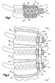
- Fig. 1 illustrates an apparatus 10 implanted in a lumbar vertebrae 12. It should be understood that the apparatus 10 could be implanted into any vertebral body, including the sacrum.
- the lumbar vertebrae 12 has a concave side surface 14.
- the apparatus 10 comprises an anchor 20 made from a biocompatible material, such as titanium or stainless steel. It is contemplated that the biocompatible material used to make the anchor 20 could also be biodegradable.
- the anchor 20 is centered about a longitudinal axis 22 (Fig. 5).
- the anchor 20 includes a platform 24 having a generally cylindrical outer surface 26 extending between oppositely disposed first and second ends 28 and 30 of the platform.
- the platform 24 includes a generally rectangular slot 32 that extends axially from the first end 28 toward the second end 30 of the platform. Adjacent the first end 28, the outer surface 26 of the platform 24 includes first and second segments of external threads 34 and 36 that are separated by the slot 32.
- the slot 32 and the threads 34 and 36 provide structure for connecting spinal fixation instrumentation to the platform 24 as discussed further below.
- the second end 30 of the platform 24 includes an end surface 38 (Fig. 6) having a convex shape that is complimentary to the shape of the concave side surface 14 of the vertebrae 12.
- the end surface 38 of the platform 24 may include barbs (not shown) or other suitable structure for fixedly engaging the side surface 14 of the vertebrae 12.
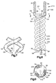
- First and second helical spikes 50 and 52 project tangentially from the end surface 38 of the platform 24.
- the helical spikes 50 and 52 resemble a pair of intertwined corkscrews. According to the embodiment illustrated in Figs. 1-6, the first and second helical spikes 50 and 52 extend around the axis 22.
- the spikes 50 and 52 extend in a helical pattern about the axis 22 at the same, constant radius R1. It is contemplated, however, that the first and second helical spikes 50 and 52 could extend about the axis 22 at different radiuses.
- the radius of one or both of the first and second helical spikes 50 and 52 could increase or decrease as the helical spikes extend away from the platform 24.
- the platform 24 and the helical spikes 50 and 52 should be less than 20mm in overall diameter.
- the anchor 20 could have an overall diameter that is greater than 20mm for certain applications, and that the anchor could be also implanted in an open surgical procedure.
- the overall diameter of the helical spikes 50 and 52 should remain less than or equal to the diameter of the platform 24.
- the first and second helical spikes 50 and 52 have the same axial length, and also have the same circular cross-sectional shape. It is contemplated, however, that the first and second helical spikes 50 and 52 could have different axial lengths. Further, it is contemplated that the helical spikes 50 and 52 could have a different cross-sectional shape, such as an oval shape. It also contemplated that the first and second helical spikes 50 and 52 could have different cross-sectional areas (i.e., one spike being thicker than the other spike). Finally, it is contemplated that the helical spikes 50 and 52 should have the same pitch, and that the pitch of the helical spikes would be selected based on the specific surgical application and quality of the bone in which the anchor 20 is to be implanted.
- Each of the first and second helical spikes 50 and 52 can be divided into three portions: a connecting portion 54, an intermediate portion 56, and a tip portion 58.
- the connecting portion 54 of each of the helical spikes 50 and 52 is located at a proximal end 60 that adjoins the end surface 38 of the platform 24.
- the connection portion 54 may include barbs (not shown) for resisting pull-out of the helical spikes 50 and 52 from the vertebrae 12.
- the connecting portion 54 of each of the helical spikes 50 and 52 is fixedly attached to the platform 24 by inserting, in a tangential direction, the proximal ends 60 of the helical spikes into openings (not shown) in the end surface 38 and welding the connecting portions 54 to the platform.
- the inserted proximal ends 60 of the helical spikes 50 and 52 help to reduce tensile bending stresses on the helical spikes under tensile (or pull-out) loads.
- the helical spikes 50 and 52 may be formed integrally with the platform 24, such as by casting the anchor 20. If the anchor 20 is cast, it is contemplated that a fillet (not shown) may be added at the junction of the helical spikes 50 and 52 and the platform 24 to strengthen the junction and minimize stress concentrations at the connecting portions 54. The fillet at the junction of the helical spikes 50 and 52 and the platform 24 also helps to reduce bending stresses in the connection portions 54 of the helical spikes under tensile (or pull-out) loads.
- the connecting portions 54 at the proximal ends 60 of the first and second helical spikes 50 and 52 are spaced 180° apart about the axis 22 to balance the anchor 20 and evenly distribute loads on the helical spikes.
- the connecting portion 54 of each of the helical spikes 50 and 52 has a first cross-sectional diameter D1 (Fig. 5).
- the tip portion 58 of each of the helical spikes 50 and 52 is located at a distal end 62 of the helical spikes.
- the intermediate portion 56 of each of the helical spikes 50 and 52 extends between the tip portion 58 and the connecting portion 54.
- the intermediate portion 56 and the tip portion 58 of each of the helical spikes 50 and 52 has a second cross-sectional diameter D2 that is less than or equal to the first cross-sectional diameter D1 of the connecting portions 54. If the second cross-sectional diameter D2 is less than the first cross-sectional diameter D1, the increased thickness of the connecting portions 54 of the helical spikes 50 and 52 will help to provide the anchor 20 with increased tensile strength at the junction of the helical spikes and the platform 24.
- each of the helical spikes 50 and 52 illustrated in Figs. 1-6 has an elongated conical shape with a sharp pointed tip 68 for penetrating into the vertebrae 12 as the platform 24 of the anchor 20 is rotated in a clockwise direction.
- Fig. 7 illustrates an alternative, self-tapping configuration for the tip portions 58 which includes a planar surface 66 for driving into the vertebrae 12, in the same manner that a wood chisel turned upside-down drives into wood, as the platform 24 is rotated. It is contemplated that the tip portions 58 could also have a pyramid shape (not shown), similar to the tip of a nail.
- a tool (not shown) is used to punch two holes (not shown) in the cortical bone (not shown) of the vertebrae 12.
- the holes are punched in locations that correspond to the spacing of the tip portions 58 of the helical spikes 50 and 52 on the anchor 20.
- one or both of the configurations of the tip portions 58 illustrated in Figs. 1-7 may be able to punch through the cortical bone upon rotation of the anchor 20, thus eliminating the need for the aforementioned tool to punch holes in the cortical bone.
- a rotatable driver 70 (Fig. 4) is inserted into the slot 32 in the platform 24.
- the driver 70 is then rotated, causing the anchor 20 to rotate as well.
- a cylindrical sleeve (not shown) may be placed around the intermediate portions 56 and the connecting portions 54 of the helical spikes 50 and 52 to prevent the helical spikes from deforming radially outward during the initial rotation of the anchor 20.
- Rotation of the anchor 20 screws the helical spikes 50 and 52 into the cancellous bone of the vertebrae 12.
- the tangentially-oriented connection between the connecting portions 54 of the helical spikes 50 and 52 and the platform 24 minimizes bending loads on the connecting portions during rotation of the anchor 20. Further, the tangentially-oriented connection ensures that the force vector resulting from torque and axial force applied by the driver 70 to platform 24 is transmitted along the helical centerline (not shown) of each of the helical spikes 50 and 52.
- the tip portion 58 of the first helical spike 50 penetrates the cancellous bone and cuts a first helical tunnel 80 (Fig. 1) through the vertebrae 12.
- the tip portion 58 of the second helical spike 52 penetrates the cancellous bone of the vertebrae 12 and cuts a second helical tunnel 82.
- the first and second helical tunnels 80 and 82 are shaped like the helical spikes 50 and 52, respectively.
- Figs. 2 and 3 illustrate how the anchor 20 is used for segmental spinal fixation of lumbar vertebrae to treat a patient with scoliosis.
- Lumbar vertebrae L3-L5, indicated by reference numbers 90, 91, and 92, respectively, are shown in Figs. 2 and 3.
- disk material 94 separates each of the lumbar vertebrae 90-92.
- the surgeon removes the disk material 94 between the vertebrae 90-92.
- the spaces left between the vertebrae 90-92 are subsequently filled with bone graft material 96 (shown schematically in Figs. 2 and 3) that fuses the vertebrae together over time.
- Spinal fixation instrumentation such as a rod or a beam 100, is used to support the vertebrae 90-92 until the vertebrae fuse together.
- the vertebrae 90-92 are each implanted with the anchor 20 according to the present invention as described above.
- the beam 100 which is bent into a desired shape by the surgeon, is placed into the slot 32 in each of the anchors 20.
- a nut 102 is then screwed onto the threads 34 and 36 on each of the platforms 24 and is tightened to secure the beam 100 to each of the anchors 20.
- the anchors 20 When implanted, the anchors 20 are subjected to substantial forces caused by human body movement and muscle memory. In some cases, these forces can tend to pull the known screws used in such an application out of the vertebrae 90-92 or can cause the screws to toggle in the vertebrae.
- the helical spike 50 and 52 when the helical spike 50 and 52 are embedded in the vertebrae 90-92, the two helical spikes of the anchors 20 provide the anchors with a high resistance to pull-out forces.
- Preliminary cadaver testing indicates that the anchor 20 is so resistant to being pulled axially from a vertebral body that the vertebral body itself is likely to fail before the anchor pulls out under high tensile load.
- the helical spikes 50 and 52, and their tangential connection with the platform 24, provide the anchors 20 with a high resistance to toggling in the vertebrae 90-92.
- Figs. 8 and 9 illustrate an apparatus 210 constructed in accordance with a second embodiment of the present invention.
- reference numbers that are the same as those used in the first embodiment of Figs. 1-6 designate parts that are the same as parts in the first embodiment.
- the apparatus 210 comprises an anchor 220 having three helical spikes 230, 231, and 232 projecting tangentially from the end surface 38 of the platform 24.
- the spikes 230-232 extend around the axis 22.
- the connecting portions 54 at the proximal ends 60 of the helical spikes 230-232 are spaced 120° apart about the axis 22, which balances the anchor 220 and evenly distributes loads on the helical spikes.
- the cross-sectional diameter of the connecting portions 54 of the helical spikes 230-232 is greater than or equal to the cross-sectional diameter of the intermediate portions 56 and the tip portions 58 of the helical spikes.
- Each of the three helical spikes 230-232 extends in a helical pattern about the axis 22 at the same, constant radius R1. It is contemplated, however, that one or more of the helical spikes 230-232 could extend about the axis 22 at different radiuses. Further, it is contemplated that the radius of one or more helical spikes 230-232 could increase or decrease as the helical spikes extend away from the platform 24.
- the three helical spikes 230-232 have the same axial length and also have the same circular cross-sectional shape. It is contemplated, however, that one or more of the helical spikes 230-232 could have different axial lengths. Further, it is contemplated that one or more of the helical spikes 230-232 could have a different cross-sectional shape, such as an oval shape. It also contemplated that the one or more of the helical spikes 230-232 could have different cross-sectional areas (i.e., one spike being thicker or thinner than the other two spikes). Finally, it is contemplated that the helical spikes 230-232 should have the same pitch, and that the pitch of the helical spikes would be selected based on the specific surgical application and quality of the bone in which the anchor 20 is to be implanted.
- each of the helical spikes 230-232 illustrated in Fig. 8 has an elongated conical shape for penetrating into a vertebrae as the platform 24 of the anchor 220 is rotated in the clockwise direction. It should be understood that the tip portions 58 of the helical spikes 230-232 of the anchor 220 could alternatively be configured like the tip portions illustrated in Fig. 7.
- the anchor 220 according to the second embodiment of Figs. 8 and 9 is implanted in a vertebrae in the same manner as the anchor 20 according to the first embodiment. Further, the anchor 220 according to the second embodiment may also be used to mount spinal fixation instrumentation in same manner as the anchor 20 according to the first embodiment.
- the anchor 220 according to the second embodiment when implanted in a vertebrae, is highly resistant to being pulled out of the vertebrae and to toggling in the vertebrae despite being subjected to substantial forces caused by human body movement and muscle memory.
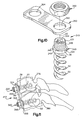
- Figs. 10 and 11 illustrate an apparatus 310 constructed in accordance with a third embodiment of the present invention.
- reference numbers that are the same as those used in the first embodiment of Figs. 1-6 designate parts that are the same as parts in the first embodiment.
- the apparatus 310 comprises an anchor 320 having a platform 324.
- the platform 324 has a threaded outer surface 330 adjacent a first end portion 332 and a cylindrical outer surface 340 adjacent a second end portion 342.
- the first end portion 332 of the platform 324 further includes an axial recess 334.
- the recess 334 has a hexagonal configuration for receiving a tool (not shown) for drivingly rotating the anchor 320.
- the first and second helical spikes 50 and 52 project from the end surface 38 of the platform 324.
- the apparatus 310 further includes a plate 350 and a nut 360.
- the plate 350 has a first opening 352 for receiving the portion of the platform 324 which has the threaded outer surface 330.
- the plate 350 has a second opening 354 for receiving a second anchor 320 (see Fig. 11) or other fixation instrumentation (not shown).
- the nut 360 screws onto the threaded outer surface 330 of the platform 324 to secure the plate 350 to the anchor 320.
- the anchor 320 according to the third embodiment of Figs. 10 and 11 is implanted in a vertebrae in the same manner as the anchor 20 according to the first embodiment.
- Fig. 11 shows a pair of the anchors 320 implanted in two cervical vertebrae 370 and 380.
- the end surface 38 of each of the anchors 320 engages a respective anterior surface on each of the vertebrae 370 and 380.
- the plate 350 connects the anchors 320 to help support the vertebrae 370 and 380 and transfer loads between the vertebrae until the bone graft material 96 fuses the vertebrae.
- the anchor 320 according to the third embodiment when implanted in the vertebrae, is highly resistant to being pulled out of the vertebrae and to toggling in the vertebrae despite being subjected to substantial forces caused by human body movement and muscle memory.
- Figs. 12 and 13 illustrate an apparatus 410 constructed in accordance with a fourth embodiment of the present invention.
- reference numbers that are the same as those used in the first embodiment of Figs. 1-6 designate parts that are the same as parts in the first embodiment.
- the apparatus 410 comprises a pair of anchors 420 extending around a longitudinal axis 422.
- Each of the anchors 420 includes a platform 424 that is substantially wider than the platform 24 of the anchor 20 in the first embodiment.
- the platform 424 has a cylindrical outer surface 426 that extends between oppositely disposed first and second end surfaces 428 and 430.
- An attachment tab 440 projects axially away from the first end surface 428 of the platform 424.
- the attachment tab 440 includes a pair of oppositely disposed planar surfaces 442 and a pair of oppositely disposed arcuate surfaces 444.
- the attachment tabs 440 provide structure for connecting spinal fixation instrumentation to each of the platforms 424 and for driving the anchors 420.
- the second end surface 430 of the platform 424 of each anchor 420 has a shape that is complimentary to the shape of an upper or lower surface of a vertebrae. Similar to the first embodiment of Fig. 1-6, the anchors 420 have first and second helical spikes 450 and 452 that project from the second end surface 430 of the platform 424.
- the helical spikes 450 and 452 extend along the axis 422, but are significantly larger in diameter than the helical spikes 50 and 52 in the first embodiment. It should be understood that the anchors 420 could alternatively have three helical spikes as shown in the second embodiment of Figs. 8 and 9.
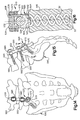
- the apparatus 410 according to the fourth embodiment of Figs. 12 and 13 is particularly useful for a corpectomy application in which a damaged vertebrae is removed. As is shown in Fig. 12, after a portion of a damaged vertebrae 460 is removed, a first one of the pair of anchors 420 is implanted into a vertebrae 462 directly above the removed vertebrae 460 and a second one of the pair of anchors 420 is implanted into a vertebrae 464 directly below the removed vertebrae.
- the anchors 420 are implanted in the vertebrae 462 and 464 in much the same manner as the anchor 20 according to the first embodiment.
- a rotatable tool (not shown) engages the planar surfaces 442 on the attachment tab 440 and rotates each of the anchors 420 to screw the helical spikes 450 and 452 of each of the anchors into the respective vertebrae 462 and 464.
- the anchors 420 are implanted so that they extend co-linearly along the axis 422.
- the helical spikes 450 and 452 of the anchor 420 in the vertebrae 462 extend in an upward direction from the platform 430 of the upper (as viewed in the Figures) anchor, while the helical spikes 450 and 452 of the other anchor in the vertebrae 464 extend in a downward direction from the platform 430 of the lower (as viewed in the Figures) anchor.
- a spinal fixation implant in the form of a cylinder member 480 connects the pair of anchors 420 to structurally support the vertebral column in the absence of the removed vertebrae 460.
- the cylinder member 480 has a cylindrical outer surface 482 and an eccentric inner surface 484.
- the cylinder member 480 has a first slot 486 at a first end 488 and a second slot 490 at a second end 492.
- the first and second slots 486 and 490 receive the attachment tabs 440 on the anchors 420 and allow the cylinder member 480 to be inserted between the anchors.
- the cylinder member 480 is then rotated relative to the anchors about the axis 422. Rotation of the cylinder member 480 brings the arcuate surfaces 444 on the attachment tabs 440 of the anchors 420 into frictional engagement with the eccentric inner surface 484 of the cylinder member, thereby securing the cylinder member.
- the anchors 420 according to the fourth embodiment when implanted, are highly resistant to being pulled out of the vertebrae 462 and 464 and to toggling in the vertebrae despite being subjected to substantial forces caused by human body movement and muscle memory.
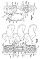
- Figs. 14-16 illustrate an apparatus 510 constructed in accordance with a fifth embodiment of the present invention.
- reference numbers that are the same as those used in the first embodiment of Figs. 1-6 designate parts that are the same as parts in the first embodiment.
- the apparatus 510 comprises an anchor 520 implanted into a sacrum 540.
- the anchor 520 includes a platform 524 having a generally cylindrical outer surface 526 extending between oppositely disposed first and second ends 528 and 530.
- the platform 524 includes a slot 532 that extends axially from the first end 528 toward the second end 530 of the platform. Adjacent the first end 528, the outer surface of the platform 524 includes first and second segments of external threads 534 and 536 that are separated by the slot 532.
- the slot 532 and the threads 534 and 536 on the platform 524 provide structure for connecting a rod 550 to the anchor 520.
- the second end 530 of the platform 524 includes an end surface 542 having a shape that is a complimentary to the shape of a surface 544 (Fig. 16) of the sacrum 540.
- the anchor 520 includes the first and second helical spikes 50 and 52 that extend from the end surface 542 of the platform 524.
- the anchor 520 according to the fifth embodiment of Figs. 14-16 is implanted in the sacrum 540 in much the same manner as the anchor 20 according to the first embodiment is implanted in the vertebrae 12.
- known screws 560 are implanted in the pedicles of lumbar vertebrae 562 and 564 above the sacrum.
- the rod 550 is then bent into a desired shape by the surgeon and placed into the slot 532 in the platform 524 of the anchor 520.
- a seat 570 is placed over the first end 528 of the platform 524 and engages the rod 550.
- a nut 572 screws down over the seat 570 and clamps the rod 550 to the anchor 520.
- the nuts 580 secure the rod 550 to the screws 560 implanted in the vertebrae 562 and 564 above the sacrum 540.
- the anchor 520 when implanted, is highly resistant to being pulled out of the sacrum 540 and to toggling in the sacrum despite being subjected to substantial forces caused by human body movement and muscle memory.
Abstract
Description
- The present invention is directed to an apparatus for implantation into a bone in a patient's spine or pelvis, and is particularly directed to an apparatus that, when implanted, is resistant to toggling in the bone and to being pulled from the bone.
- Bone screws are used in the medical field for a variety of purposes. Typical uses for bone screws, also referred as bone anchors, include treating a bone fracture, attaching a corrective device to parts of a fractured bone in an area adjacent to the fracture, and attaching a corrective device to a group of bones, such as vertebrae of a spinal column.
- Most known bone screws use a conventional screw design, i.e. a solid shank, with one or more external thread convolutions. The solid shank and external threads of the conventional bone screws can cause the bone screws to displace an undesirably large amount of bone when implanted. It is also known to use a corkscrew-style helical spike as a tissue anchor. The known corkscrew-style tissue anchors, when implanted, displace less bone than the conventional bone screws, but are generally not able to withstand high tensile loads without structural failure.
European Patent No. 0 374 088 A1 discloses a bone screw having a twin-corkscrew design. In this twin-corkscrew design, which is formed by drilling a passage up through a screw having a solid shank and then machining out the material between the two corkscrews, the junction of the corkscrews with the shank is unlikely to be capable of structurally withstanding high tensile loads and repetitive fatigue loads. This structural weakness in the design of the screw in theEP 0 374 088 document is further compounded by the corkscrews having a larger overall diameter than the head of the screw where torque is applied. - Tacks having spiral fixing members for fastening soft tissue to soft tissue or sutures to tissue, such as that described in
US 5,728,116 , are known. These are mechanically insufficient for penetration into bone. - One of the more challenging applications of a bone screw is implantation of the screw into the cancellous bone of a patient's spine or pelvis. For example, bone screws are frequently implanted into the cancellous bone of a patient's lumbar vertebrae during a spinal fixation procedure to correct scoliosis. Once implanted, the bone screws are used to mount suitable spinal fixation instrumentation, such as clamps, rods, and plates. Unfortunately, many of the known bone screws, such as those described above, can be susceptible to toggling in the vertebral body and can also pull out of the vertebral body due to the substantial forces on the screws from human body movement and muscle memory. In order to achieve a high pull-out resistance, it is known to thread a bone screw all of the way through a vertebrae and place a nut on the opposite side. However, use of such a nut increases the complexity of the surgical procedure.
- Hence, it is desirable to provide an apparatus for implantation into a bone in a patient's spine or pelvis in a minimally invasive endoscopic procedure, wherein the apparatus provides a platform for connecting spinal fixation instrumentation and, when implanted, is highly resistant to toggling in the bone and to being pulled out of the bone despite the substantial forces on the apparatus from human body movement and muscle memory.
- The present invention is an apparatus for implantation into a bone in a patient's spine or pelvis. The apparatus, when implanted, is resistant to toggling in the bone and to being pulled from the bone. The apparatus comprises a platform having a first surface for facing a bone in a patient's spine or pelvis. The platform includes structure for connection to a spinal fixation implant. The apparatus further comprises at least one helical spike for embedding into the bone upon rotation of the platform. The helical spike projects tangentially from the platform and extends around a longitudinal axis. The helical spike has a tip portion at a distal end which penetrates into the bone as the platform is rotated. The helical spike further has a connecting portion at a proximal end connected to the platform and an intermediate portion extending between the connecting portion and the tip portion.
- In accordance with one embodiment of the present invention, the apparatus comprises a pair of helical spikes extending around the longitudinal axis. The proximal ends of the pair of helical spikes are spaced 180° apart.
- In accordance with another embodiment of the present invention, the apparatus comprises three helical spikes extending around the longitudinal axis. The proximal ends of the three helical spikes are spaced 120° apart.
- In accordance with yet another embodiment, the present invention is an apparatus comprising at least one anchor for implantation into a bone. The anchor, when implanted, is resistant to toggling in the bone and to being pulled from the bone. The apparatus further comprises a spinal fixation implant for extending between and connecting a plurality of bones. The anchor includes a platform having a first surface for facing the bone. The platform further has structure for connection with the spinal fixation implant. The anchor further includes at least two helical spikes for embedding into the bone upon rotation of the platform. The helical spikes are spaced apart and project tangentially from the first surface on the platform. The helical spikes extend around a longitudinal axis. Each of the helical spikes has a tip portion at a distal end which penetrates into the bone as the platform is rotated. Each of the helical spikes further has a connecting portion at a proximal end that is connected to the platform, and an intermediate portion extending between the connecting portion and the tip portion.
- In accordance with still another embodiment of the present invention, the apparatus comprises a first anchor for implantation into a first bone and a second anchor for implantation into a second bone spaced from the first bone. Each of the first and second anchors extends co-linearly along the longitudinal axis. The spikes that project from the platform of the first anchor extend in a first direction. The spikes that project from the platform of the second anchor extend in a second direction opposite the first direction. The spinal fixation implant comprises a member extending along the longitudinal axis and interconnecting the first and second anchors.
- The foregoing and other features of the present invention will become apparent to those skilled in the art to which the present invention relates upon reading the following description with reference to the accompanying drawings, in which:
- Fig. 1 is a schematic anterior view of an apparatus constructed in accordance with the present invention implanted in a vertebral body;
- Fig. 2 is a schematic anterior view of several vertebral bodies implanted with the apparatus of Fig. 1 and connected by a spinal fixation implant in accordance with the present invention;
- Fig. 3 is a side view taken along line 3-3 in Fig. 2;
- Fig. 4 is an exploded perspective view of the apparatus of Fig. 2, and illustrates a driver for rotating the apparatus;
- Fig. 5 is a side view of the apparatus of Fig 1;
- Fig. 6 is a sectional view taken along 6-6 in Fig. 5;
- Fig. 7 illustrates an alternate configuration for an end portion of the apparatus of Fig. 1;
- Fig. 8 is a side view illustrating a second embodiment of an apparatus in accordance with the present invention;
- Fig. 9 is a sectional view taken along line 9-9 in Fig. 8;
- Fig. 10 is an exploded perspective view illustrating a third embodiment of an apparatus in accordance with the present invention;
- Fig. 11 is a schematic side view of the apparatus of Fig. 10 implanted in a pair of vertebral bodies;
- Fig. 12 is a schematic view, partially in section, of a fourth embodiment of the present invention;
- Fig. 13 is an exploded perspective view of the apparatus of Fig. 12;
- Fig. 14 is a schematic posterior view illustrating a fifth embodiment of the present invention;
- Fig. 15 is a side view of Fig. 14; and
- Fig. 16 is a sectional view taken along line 16-16 in Fig. 15.
- The present invention is directed to an apparatus for implantation into a bone in a patient's spine or pelvis, and is particularly directed to an apparatus that, when implanted, is resistant to toggling in the bone and to being pulled from the bone. As representative of the present invention, Fig. 1 illustrates an
apparatus 10 implanted in alumbar vertebrae 12. It should be understood that theapparatus 10 could be implanted into any vertebral body, including the sacrum. Thelumbar vertebrae 12 has aconcave side surface 14. - The
apparatus 10 comprises ananchor 20 made from a biocompatible material, such as titanium or stainless steel. It is contemplated that the biocompatible material used to make theanchor 20 could also be biodegradable. Theanchor 20 is centered about a longitudinal axis 22 (Fig. 5). Theanchor 20 includes aplatform 24 having a generally cylindricalouter surface 26 extending between oppositely disposed first and second ends 28 and 30 of the platform. Theplatform 24 includes a generallyrectangular slot 32 that extends axially from thefirst end 28 toward thesecond end 30 of the platform. Adjacent thefirst end 28, theouter surface 26 of theplatform 24 includes first and second segments ofexternal threads slot 32. Theslot 32 and thethreads platform 24 as discussed further below. Thesecond end 30 of theplatform 24 includes an end surface 38 (Fig. 6) having a convex shape that is complimentary to the shape of theconcave side surface 14 of thevertebrae 12. Theend surface 38 of theplatform 24 may include barbs (not shown) or other suitable structure for fixedly engaging theside surface 14 of thevertebrae 12. - First and second
helical spikes end surface 38 of theplatform 24. Thehelical spikes helical spikes axis 22. Thespikes axis 22 at the same, constant radius R1. It is contemplated, however, that the first and secondhelical spikes axis 22 at different radiuses. Further, it is contemplated that the radius of one or both of the first and secondhelical spikes platform 24. In order for theanchor 20 to be implanted endoscopically through a typical cannula (not shown), theplatform 24 and thehelical spikes anchor 20 could have an overall diameter that is greater than 20mm for certain applications, and that the anchor could be also implanted in an open surgical procedure. However, for structural stability reasons, the overall diameter of thehelical spikes platform 24. - In the illustrated embodiment of Figs. 1-6, the first and second
helical spikes helical spikes helical spikes helical spikes helical spikes anchor 20 is to be implanted. - Each of the first and second
helical spikes portion 54, anintermediate portion 56, and atip portion 58. The connectingportion 54 of each of thehelical spikes proximal end 60 that adjoins theend surface 38 of theplatform 24. Theconnection portion 54 may include barbs (not shown) for resisting pull-out of thehelical spikes vertebrae 12. According to one method for manufacturing theanchor 20, the connectingportion 54 of each of thehelical spikes platform 24 by inserting, in a tangential direction, the proximal ends 60 of the helical spikes into openings (not shown) in theend surface 38 and welding the connectingportions 54 to the platform. The inserted proximal ends 60 of thehelical spikes - Alternatively, the
helical spikes platform 24, such as by casting theanchor 20. If theanchor 20 is cast, it is contemplated that a fillet (not shown) may be added at the junction of thehelical spikes platform 24 to strengthen the junction and minimize stress concentrations at the connectingportions 54. The fillet at the junction of thehelical spikes platform 24 also helps to reduce bending stresses in theconnection portions 54 of the helical spikes under tensile (or pull-out) loads. - As best seen in Fig. 6, the connecting
portions 54 at the proximal ends 60 of the first and secondhelical spikes axis 22 to balance theanchor 20 and evenly distribute loads on the helical spikes. The connectingportion 54 of each of thehelical spikes - The
tip portion 58 of each of thehelical spikes distal end 62 of the helical spikes. Theintermediate portion 56 of each of thehelical spikes tip portion 58 and the connectingportion 54. Theintermediate portion 56 and thetip portion 58 of each of thehelical spikes portions 54. If the second cross-sectional diameter D2 is less than the first cross-sectional diameter D1, the increased thickness of the connectingportions 54 of thehelical spikes anchor 20 with increased tensile strength at the junction of the helical spikes and theplatform 24. - The
tip portion 58 of each of thehelical spikes pointed tip 68 for penetrating into thevertebrae 12 as theplatform 24 of theanchor 20 is rotated in a clockwise direction. Fig. 7 illustrates an alternative, self-tapping configuration for thetip portions 58 which includes aplanar surface 66 for driving into thevertebrae 12, in the same manner that a wood chisel turned upside-down drives into wood, as theplatform 24 is rotated. It is contemplated that thetip portions 58 could also have a pyramid shape (not shown), similar to the tip of a nail. - To implant the
anchor 20, a tool (not shown) is used to punch two holes (not shown) in the cortical bone (not shown) of thevertebrae 12. The holes are punched in locations that correspond to the spacing of thetip portions 58 of thehelical spikes anchor 20. It should be noted that one or both of the configurations of thetip portions 58 illustrated in Figs. 1-7 may be able to punch through the cortical bone upon rotation of theanchor 20, thus eliminating the need for the aforementioned tool to punch holes in the cortical bone. - The
tip portions 58 are then placed in the holes in thevertebrae 12 and a rotatable driver 70 (Fig. 4) is inserted into theslot 32 in theplatform 24. Thedriver 70 is then rotated, causing theanchor 20 to rotate as well. It is contemplated that a cylindrical sleeve (not shown) may be placed around theintermediate portions 56 and the connectingportions 54 of thehelical spikes anchor 20. - Rotation of the
anchor 20 screws thehelical spikes vertebrae 12. The tangentially-oriented connection between the connectingportions 54 of thehelical spikes platform 24 minimizes bending loads on the connecting portions during rotation of theanchor 20. Further, the tangentially-oriented connection ensures that the force vector resulting from torque and axial force applied by thedriver 70 toplatform 24 is transmitted along the helical centerline (not shown) of each of thehelical spikes - As the
anchor 20 is rotated, thetip portion 58 of the firsthelical spike 50 penetrates the cancellous bone and cuts a first helical tunnel 80 (Fig. 1) through thevertebrae 12. Simultaneously, thetip portion 58 of the secondhelical spike 52 penetrates the cancellous bone of thevertebrae 12 and cuts a secondhelical tunnel 82. The first and secondhelical tunnels helical spikes anchor 20 embeds thehelical spikes vertebrae 12. Theanchor 20 is rotated until theconvex end surface 38 of theplatform 24 seats against theconcave side surface 14 of thevertebrae 12 as shown in Fig. 1. - Figs. 2 and 3 illustrate how the
anchor 20 is used for segmental spinal fixation of lumbar vertebrae to treat a patient with scoliosis. Lumbar vertebrae L3-L5, indicated byreference numbers disk material 94 separates each of the lumbar vertebrae 90-92. However, in order to correct the scoliosis, the surgeon removes thedisk material 94 between the vertebrae 90-92. The spaces left between the vertebrae 90-92 are subsequently filled with bone graft material 96 (shown schematically in Figs. 2 and 3) that fuses the vertebrae together over time. Spinal fixation instrumentation, such as a rod or abeam 100, is used to support the vertebrae 90-92 until the vertebrae fuse together. - As shown in Figs. 2 and 3, the vertebrae 90-92 are each implanted with the
anchor 20 according to the present invention as described above. Thebeam 100, which is bent into a desired shape by the surgeon, is placed into theslot 32 in each of theanchors 20. Anut 102 is then screwed onto thethreads platforms 24 and is tightened to secure thebeam 100 to each of theanchors 20. - When implanted, the
anchors 20 are subjected to substantial forces caused by human body movement and muscle memory. In some cases, these forces can tend to pull the known screws used in such an application out of the vertebrae 90-92 or can cause the screws to toggle in the vertebrae. However, when thehelical spike anchors 20 provide the anchors with a high resistance to pull-out forces. Preliminary cadaver testing indicates that theanchor 20 is so resistant to being pulled axially from a vertebral body that the vertebral body itself is likely to fail before the anchor pulls out under high tensile load. Further, thehelical spikes platform 24, provide theanchors 20 with a high resistance to toggling in the vertebrae 90-92. - Figs. 8 and 9 illustrate an
apparatus 210 constructed in accordance with a second embodiment of the present invention. In the second embodiment of Figs. 8 and 9, reference numbers that are the same as those used in the first embodiment of Figs. 1-6 designate parts that are the same as parts in the first embodiment. - According to the second embodiment, the
apparatus 210 comprises ananchor 220 having threehelical spikes end surface 38 of theplatform 24. The spikes 230-232 extend around theaxis 22. As shown in Fig. 9, the connectingportions 54 at the proximal ends 60 of the helical spikes 230-232 are spaced 120° apart about theaxis 22, which balances theanchor 220 and evenly distributes loads on the helical spikes. As in the first embodiment of Figs. 1-6, in the second embodiment of Figs. 8 and 9, the cross-sectional diameter of the connectingportions 54 of the helical spikes 230-232 is greater than or equal to the cross-sectional diameter of theintermediate portions 56 and thetip portions 58 of the helical spikes. - Each of the three helical spikes 230-232 extends in a helical pattern about the
axis 22 at the same, constant radius R1. It is contemplated, however, that one or more of the helical spikes 230-232 could extend about theaxis 22 at different radiuses. Further, it is contemplated that the radius of one or more helical spikes 230-232 could increase or decrease as the helical spikes extend away from theplatform 24. - As shown in Fig. 8, the three helical spikes 230-232 have the same axial length and also have the same circular cross-sectional shape. It is contemplated, however, that one or more of the helical spikes 230-232 could have different axial lengths. Further, it is contemplated that one or more of the helical spikes 230-232 could have a different cross-sectional shape, such as an oval shape. It also contemplated that the one or more of the helical spikes 230-232 could have different cross-sectional areas (i.e., one spike being thicker or thinner than the other two spikes). Finally, it is contemplated that the helical spikes 230-232 should have the same pitch, and that the pitch of the helical spikes would be selected based on the specific surgical application and quality of the bone in which the
anchor 20 is to be implanted. - The
tip portion 58 of each of the helical spikes 230-232 illustrated in Fig. 8 has an elongated conical shape for penetrating into a vertebrae as theplatform 24 of theanchor 220 is rotated in the clockwise direction. It should be understood that thetip portions 58 of the helical spikes 230-232 of theanchor 220 could alternatively be configured like the tip portions illustrated in Fig. 7. - The
anchor 220 according to the second embodiment of Figs. 8 and 9 is implanted in a vertebrae in the same manner as theanchor 20 according to the first embodiment. Further, theanchor 220 according to the second embodiment may also be used to mount spinal fixation instrumentation in same manner as theanchor 20 according to the first embodiment. Theanchor 220 according to the second embodiment, when implanted in a vertebrae, is highly resistant to being pulled out of the vertebrae and to toggling in the vertebrae despite being subjected to substantial forces caused by human body movement and muscle memory. - Figs. 10 and 11 illustrate an
apparatus 310 constructed in accordance with a third embodiment of the present invention. In the third embodiment of Figs. 10 and 11, reference numbers that are the same as those used in the first embodiment of Figs. 1-6 designate parts that are the same as parts in the first embodiment. - According to the third embodiment, the
apparatus 310 comprises ananchor 320 having aplatform 324. Theplatform 324 has a threadedouter surface 330 adjacent afirst end portion 332 and a cylindricalouter surface 340 adjacent asecond end portion 342. Thefirst end portion 332 of theplatform 324 further includes anaxial recess 334. Therecess 334 has a hexagonal configuration for receiving a tool (not shown) for drivingly rotating theanchor 320. The first and secondhelical spikes end surface 38 of theplatform 324. - The
apparatus 310 further includes aplate 350 and anut 360. Theplate 350 has afirst opening 352 for receiving the portion of theplatform 324 which has the threadedouter surface 330. Theplate 350 has asecond opening 354 for receiving a second anchor 320 (see Fig. 11) or other fixation instrumentation (not shown). When theanchor 320 is implanted in a vertebrae, thenut 360 screws onto the threadedouter surface 330 of theplatform 324 to secure theplate 350 to theanchor 320. - The
anchor 320 according to the third embodiment of Figs. 10 and 11 is implanted in a vertebrae in the same manner as theanchor 20 according to the first embodiment. Fig. 11 shows a pair of theanchors 320 implanted in twocervical vertebrae end surface 38 of each of theanchors 320 engages a respective anterior surface on each of thevertebrae plate 350 connects theanchors 320 to help support thevertebrae bone graft material 96 fuses the vertebrae. Like theanchor 20 according to the first embodiment, theanchor 320 according to the third embodiment, when implanted in the vertebrae, is highly resistant to being pulled out of the vertebrae and to toggling in the vertebrae despite being subjected to substantial forces caused by human body movement and muscle memory. - Figs. 12 and 13 illustrate an
apparatus 410 constructed in accordance with a fourth embodiment of the present invention. In the fourth embodiment of Figs. 12 and 13, reference numbers that are the same as those used in the first embodiment of Figs. 1-6 designate parts that are the same as parts in the first embodiment. - According to the fourth embodiment, the
apparatus 410 comprises a pair ofanchors 420 extending around alongitudinal axis 422. Each of theanchors 420 includes aplatform 424 that is substantially wider than theplatform 24 of theanchor 20 in the first embodiment. Theplatform 424 has a cylindricalouter surface 426 that extends between oppositely disposed first and second end surfaces 428 and 430. Anattachment tab 440 projects axially away from thefirst end surface 428 of theplatform 424. Theattachment tab 440 includes a pair of oppositely disposedplanar surfaces 442 and a pair of oppositely disposedarcuate surfaces 444. - The
attachment tabs 440 provide structure for connecting spinal fixation instrumentation to each of theplatforms 424 and for driving theanchors 420. Thesecond end surface 430 of theplatform 424 of eachanchor 420 has a shape that is complimentary to the shape of an upper or lower surface of a vertebrae. Similar to the first embodiment of Fig. 1-6, theanchors 420 have first and secondhelical spikes second end surface 430 of theplatform 424. Thehelical spikes axis 422, but are significantly larger in diameter than thehelical spikes anchors 420 could alternatively have three helical spikes as shown in the second embodiment of Figs. 8 and 9. - The
apparatus 410 according to the fourth embodiment of Figs. 12 and 13 is particularly useful for a corpectomy application in which a damaged vertebrae is removed. As is shown in Fig. 12, after a portion of a damagedvertebrae 460 is removed, a first one of the pair ofanchors 420 is implanted into avertebrae 462 directly above the removedvertebrae 460 and a second one of the pair ofanchors 420 is implanted into avertebrae 464 directly below the removed vertebrae. - The
anchors 420 are implanted in thevertebrae anchor 20 according to the first embodiment. A rotatable tool (not shown) engages theplanar surfaces 442 on theattachment tab 440 and rotates each of theanchors 420 to screw thehelical spikes respective vertebrae anchors 420 are implanted so that they extend co-linearly along theaxis 422. When implanted, thehelical spikes anchor 420 in thevertebrae 462 extend in an upward direction from theplatform 430 of the upper (as viewed in the Figures) anchor, while thehelical spikes vertebrae 464 extend in a downward direction from theplatform 430 of the lower (as viewed in the Figures) anchor. - A spinal fixation implant in the form of a
cylinder member 480 connects the pair ofanchors 420 to structurally support the vertebral column in the absence of the removedvertebrae 460. Thecylinder member 480 has a cylindricalouter surface 482 and an eccentricinner surface 484. Thecylinder member 480 has afirst slot 486 at afirst end 488 and asecond slot 490 at asecond end 492. The first andsecond slots attachment tabs 440 on theanchors 420 and allow thecylinder member 480 to be inserted between the anchors. Once inserted between theanchors 420, thecylinder member 480 is then rotated relative to the anchors about theaxis 422. Rotation of thecylinder member 480 brings thearcuate surfaces 444 on theattachment tabs 440 of theanchors 420 into frictional engagement with the eccentricinner surface 484 of the cylinder member, thereby securing the cylinder member. - As with the previous embodiments, the
anchors 420 according to the fourth embodiment, when implanted, are highly resistant to being pulled out of thevertebrae - Figs. 14-16 illustrate an apparatus 510 constructed in accordance with a fifth embodiment of the present invention. In the fifth embodiment of Figs. 14-16, reference numbers that are the same as those used in the first embodiment of Figs. 1-6 designate parts that are the same as parts in the first embodiment.
- According to the fifth embodiment, the apparatus 510 comprises an
anchor 520 implanted into asacrum 540. Theanchor 520 includes aplatform 524 having a generally cylindricalouter surface 526 extending between oppositely disposed first and second ends 528 and 530. Theplatform 524 includes aslot 532 that extends axially from thefirst end 528 toward thesecond end 530 of the platform. Adjacent thefirst end 528, the outer surface of theplatform 524 includes first and second segments ofexternal threads slot 532. Theslot 532 and thethreads platform 524 provide structure for connecting arod 550 to theanchor 520. - The
second end 530 of theplatform 524 includes anend surface 542 having a shape that is a complimentary to the shape of a surface 544 (Fig. 16) of thesacrum 540. Theanchor 520 includes the first and secondhelical spikes end surface 542 of theplatform 524. - The
anchor 520 according to the fifth embodiment of Figs. 14-16 is implanted in thesacrum 540 in much the same manner as theanchor 20 according to the first embodiment is implanted in thevertebrae 12. As shown in Fig. 15, in addition to theanchor 520 being implanted in thesacrum 540, knownscrews 560 are implanted in the pedicles oflumbar vertebrae rod 550 is then bent into a desired shape by the surgeon and placed into theslot 532 in theplatform 524 of theanchor 520. Aseat 570 is placed over thefirst end 528 of theplatform 524 and engages therod 550. Anut 572 screws down over theseat 570 and clamps therod 550 to theanchor 520. In a similar fashion, thenuts 580 secure therod 550 to thescrews 560 implanted in thevertebrae sacrum 540. - As in the first embodiment, the
anchor 520 according to the fifth embodiment, when implanted, is highly resistant to being pulled out of thesacrum 540 and to toggling in the sacrum despite being subjected to substantial forces caused by human body movement and muscle memory. - From the above description of the invention, those skilled in the art will perceive improvements, changes and modifications. It should be understood that the present invention can be used for a variety of purposes and implanted in other bones besides bones in the vertebral column. Further, it should be understood that more than one of the apparatuses disclosed herein may be implanted into a single bone, such as a vertebral body. Such improvements, changes and modifications within the skill of the art are intended to be covered by the appended claims.
Claims (9)
- An apparatus (10) for implantation into a bone (12) in a patient's spine or pelvis, said apparatus (10), when implanted, being resistant to toggling in the bone (12) and to being pulled from the bone (12), said apparatus (10) comprising:a platform (24) having a first surface (38) for facing a bone (12) in a patient's spine or pelvis, said first surface (38) being solid and extending generally transverse to a longitudinal axis (22) of said apparatus (10), said platform (24) including structure (32,34,36) for connection to a spinal fixation implant; andat least one helical spike (50,52) for embedding into the bone (12) upon rotation of said platform (24), said at least one helical spike (50,52) projecting tangentially from said first surface (38) of said platform (24) and extending around said longitudinal axis (22), said at least one helical spike (50,52) having a proximal end and a distal end;said at least one helical spike(50,52) including a tip portion (58) at said distal end which penetrates into the bone (12) as said platform (24) is rotated, a connecting portion (54) at said proximal end connected to said first surface (38) of said platform (24), and an intermediate portion (56) extending between said connecting portion (54) and said tip portion (58).
- The apparatus (10) of claim 1 wherein said connecting portion (54) of said at least one helical spike (50,52) has a first cross-sectional diameter and said intermediate portion (56) of said at least one helical spike (50,52) has a second cross-sectional diameter that is less than said first cross-sectional diameter.
- The apparatus (10) of claim 1 wherein said connecting portion (54) of said at least one helical spike (50,52) has a first cross-sectional diameter and said intermediate portion (56) of said at least one helical spike (50,52) has a second cross-sectional diameter that is equal to said first cross-sectional diameter.
- The apparatus (10) of claim 1 wherein said platform (24) and said at least one helical spike (50,52) are made of a biocompatible material.
- The apparatus (10) of claim 1 comprising a pair of helical spikes (50,52) extending around said longitudinal axis (22), said proximal ends of said pair of helical spikes (50,52) being spaced 180° apart.
- The apparatus (10) of claim 1 comprising three helical spikes (230,231,232) extending around said longitudinal axis (22), said proximal ends of said helical spikes (230,231,232) being spaced 120° apart.
- The apparatus (10) of claim 1 wherein said first surface (38) has a shape that is complimentary to the shape of an outer surface of the bone (12) for engaging the outer surface of the bone (12).
- The apparatus (10) of claim 1 wherein said tip portion (58) of said at least one helical spike (50,52) has an elongated conical shape with a sharp pointed tip that penetrates into the bone (12) as said platform (24) is rotated.
- The apparatus (10) of claim 1 wherein said tip portion (58) of said at least one helical spike (50,52) has a self-penetrating terminal end that includes a planar surface for driving into the bone (12) as said platform (24) is rotated.
Applications Claiming Priority (5)
| Application Number | Priority Date | Filing Date | Title |
|---|---|---|---|
| US23827100P | 2000-10-05 | 2000-10-05 | |
| US238271P | 2000-10-05 | ||
| US09/708,940 US6551322B1 (en) | 2000-10-05 | 2000-11-08 | Apparatus for implantation into bone |
| US708940 | 2000-11-08 | ||
| PCT/US2001/031048 WO2002028297A1 (en) | 2000-10-05 | 2001-09-28 | Apparatus for implantation into bone |
Publications (3)
| Publication Number | Publication Date |
|---|---|
| EP1322242A1 EP1322242A1 (en) | 2003-07-02 |
| EP1322242A4 EP1322242A4 (en) | 2006-06-07 |
| EP1322242B1 true EP1322242B1 (en) | 2007-08-15 |
Family
ID=26931501
Family Applications (1)
| Application Number | Title | Priority Date | Filing Date |
|---|---|---|---|
| EP01981368A Expired - Lifetime EP1322242B1 (en) | 2000-10-05 | 2001-09-28 | Apparatus for implantation into bone |
Country Status (7)
| Country | Link |
|---|---|
| US (1) | US6551322B1 (en) |
| EP (1) | EP1322242B1 (en) |
| JP (2) | JP2004510488A (en) |
| AU (2) | AU2002213014B2 (en) |
| CA (1) | CA2424173C (en) |
| DE (1) | DE60129998T2 (en) |
| WO (1) | WO2002028297A1 (en) |
Families Citing this family (125)
| Publication number | Priority date | Publication date | Assignee | Title |
|---|---|---|---|---|
| US6648890B2 (en) | 1996-11-12 | 2003-11-18 | Triage Medical, Inc. | Bone fixation system with radially extendable anchor |
| US20050143734A1 (en) * | 1996-11-12 | 2005-06-30 | Cachia Victor V. | Bone fixation system with radially extendable anchor |
| EP2314257B9 (en) | 2000-05-01 | 2013-02-27 | ArthroSurface, Inc. | System for joint resurface repair |
| US7678151B2 (en) | 2000-05-01 | 2010-03-16 | Ek Steven W | System and method for joint resurface repair |
| US8177841B2 (en) | 2000-05-01 | 2012-05-15 | Arthrosurface Inc. | System and method for joint resurface repair |
| US20040230315A1 (en) * | 2000-05-01 | 2004-11-18 | Ek Steven W. | Articular surface implant |
| US7163541B2 (en) | 2002-12-03 | 2007-01-16 | Arthrosurface Incorporated | Tibial resurfacing system |
| US6610067B2 (en) | 2000-05-01 | 2003-08-26 | Arthrosurface, Incorporated | System and method for joint resurface repair |
| US7713305B2 (en) | 2000-05-01 | 2010-05-11 | Arthrosurface, Inc. | Articular surface implant |
| US6953462B2 (en) | 2000-10-05 | 2005-10-11 | The Cleveland Clinic Foundation | Apparatus for implantation into bone |
| US6511481B2 (en) * | 2001-03-30 | 2003-01-28 | Triage Medical, Inc. | Method and apparatus for fixation of proximal femoral fractures |
| US6887243B2 (en) * | 2001-03-30 | 2005-05-03 | Triage Medical, Inc. | Method and apparatus for bone fixation with secondary compression |
| FR2823095B1 (en) * | 2001-04-06 | 2004-02-06 | Ldr Medical | RACHIS OSTEOSYNTHESIS DEVICE AND PLACEMENT METHOD |
| RU2194274C1 (en) * | 2001-09-18 | 2002-12-10 | ЗАО "Нефтегазкомплектсервис" | Technology of intratube ultrasonic flaw detection |
| FR2831048B1 (en) * | 2001-10-18 | 2004-09-17 | Ldr Medical | PROGRESSIVE APPROACH OSTEOSYNTHESIS DEVICE AND PRE-ASSEMBLY PROCESS |
| FR2831049B1 (en) * | 2001-10-18 | 2004-08-13 | Ldr Medical | PLATE FOR OSTEOSYNTHESIS DEVICE AND PRE-ASSEMBLY METHOD |
| FR2833151B1 (en) | 2001-12-12 | 2004-09-17 | Ldr Medical | BONE ANCHORING IMPLANT WITH POLYAXIAL HEAD |
| EP1493831A4 (en) * | 2002-04-05 | 2006-12-06 | Nippon Steel Corp | Pealite based rail excellent in wear resistance and ductility and method for production thereof |
| US6966910B2 (en) * | 2002-04-05 | 2005-11-22 | Stephen Ritland | Dynamic fixation device and method of use |
| US7169157B2 (en) * | 2002-04-17 | 2007-01-30 | Tyco Healthcare Group Lp | Tacking tool and tack |
| US6793678B2 (en) | 2002-06-27 | 2004-09-21 | Depuy Acromed, Inc. | Prosthetic intervertebral motion disc having dampening |
| US7824429B2 (en) * | 2002-07-19 | 2010-11-02 | Interventional Spine, Inc. | Method and apparatus for spinal fixation |
| US7430616B2 (en) * | 2002-09-16 | 2008-09-30 | Clearcube Technology, Inc. | System and method for reducing user-application interactions to archivable form |
| US20040078084A1 (en) * | 2002-10-22 | 2004-04-22 | Ricardo Albertorio | Prosthetic implant and method of use |
| US7901408B2 (en) | 2002-12-03 | 2011-03-08 | Arthrosurface, Inc. | System and method for retrograde procedure |
| US7070601B2 (en) * | 2003-01-16 | 2006-07-04 | Triage Medical, Inc. | Locking plate for bone anchors |
| US8388624B2 (en) | 2003-02-24 | 2013-03-05 | Arthrosurface Incorporated | Trochlear resurfacing system and method |
| US6951561B2 (en) * | 2003-05-06 | 2005-10-04 | Triage Medical, Inc. | Spinal stabilization device |
| DE102004021861A1 (en) | 2004-05-04 | 2005-11-24 | Biedermann Motech Gmbh | Implant for temporary or permanent replacement of vertebra or intervertebral disk, comprising solid central element and outer elements with openings |
| WO2005039454A2 (en) * | 2003-10-17 | 2005-05-06 | Biedermann Motech Gmbh | Flexible implant |
| US7951163B2 (en) | 2003-11-20 | 2011-05-31 | Arthrosurface, Inc. | Retrograde excision system and apparatus |
| EP1845890A4 (en) | 2003-11-20 | 2010-06-09 | Arthrosurface Inc | System and method for retrograde procedure |
| AU2004293042A1 (en) | 2003-11-20 | 2005-06-09 | Arthrosurface, Inc. | Retrograde delivery of resurfacing devices |
| EP1765201A4 (en) | 2004-06-28 | 2013-01-23 | Arthrosurface Inc | System for articular surface replacement |
| WO2006023793A2 (en) * | 2004-08-20 | 2006-03-02 | Triage Medical, Inc. | Method and apparatus for delivering an agent |
| US7766940B2 (en) * | 2004-12-30 | 2010-08-03 | Depuy Spine, Inc. | Posterior stabilization system |
| US20060084976A1 (en) | 2004-09-30 | 2006-04-20 | Depuy Spine, Inc. | Posterior stabilization systems and methods |
| US8092496B2 (en) | 2004-09-30 | 2012-01-10 | Depuy Spine, Inc. | Methods and devices for posterior stabilization |
| US7896906B2 (en) * | 2004-12-30 | 2011-03-01 | Depuy Spine, Inc. | Artificial facet joint |
| US7828853B2 (en) | 2004-11-22 | 2010-11-09 | Arthrosurface, Inc. | Articular surface implant and delivery system |
| ATE524121T1 (en) | 2004-11-24 | 2011-09-15 | Abdou Samy | DEVICES FOR PLACING AN ORTHOPEDIC INTERVERTEBRAL IMPLANT |
| US7909826B2 (en) | 2005-03-24 | 2011-03-22 | Depuy Spine, Inc. | Low profile spinal tethering methods |
| US8894661B2 (en) * | 2007-08-16 | 2014-11-25 | Smith & Nephew, Inc. | Helicoil interference fixation system for attaching a graft ligament to a bone |
| US20080154314A1 (en) * | 2006-08-16 | 2008-06-26 | Mcdevitt Dennis M | Composite interference screw for attaching a graft ligament to a bone, and other apparatus for making attachments to bone |
| US8105382B2 (en) | 2006-12-07 | 2012-01-31 | Interventional Spine, Inc. | Intervertebral implant |
| AU2007332787A1 (en) | 2006-12-11 | 2008-06-19 | Arthrosurface Incorporated | Retrograde resection apparatus and method |
| US20080195113A1 (en) * | 2007-02-14 | 2008-08-14 | Arthrosurface Incorporated | Bone Cement Delivery Device |
| US7846123B2 (en) | 2007-04-24 | 2010-12-07 | Emory University | Conduit device and system for implanting a conduit device in a tissue wall |
| US7998176B2 (en) * | 2007-06-08 | 2011-08-16 | Interventional Spine, Inc. | Method and apparatus for spinal stabilization |
| FR2916956B1 (en) | 2007-06-08 | 2012-12-14 | Ldr Medical | INTERSOMATIC CAGE, INTERVERTEBRAL PROSTHESIS, ANCHORING DEVICE AND IMPLANTATION INSTRUMENTATION |
| US8900307B2 (en) | 2007-06-26 | 2014-12-02 | DePuy Synthes Products, LLC | Highly lordosed fusion cage |
| CN101909548B (en) | 2008-01-17 | 2014-07-30 | 斯恩蒂斯有限公司 | An expandable intervertebral implant and associated method of manufacturing the same |
| EP2262448A4 (en) | 2008-03-03 | 2014-03-26 | Arthrosurface Inc | Bone resurfacing system and method |
| WO2009124269A1 (en) | 2008-04-05 | 2009-10-08 | Synthes Usa, Llc | Expandable intervertebral implant |
| CA2733783A1 (en) * | 2008-08-15 | 2010-02-18 | Kinetic Spine Technologies Inc. | Dynamic pedicle screw |
| US9526620B2 (en) | 2009-03-30 | 2016-12-27 | DePuy Synthes Products, Inc. | Zero profile spinal fusion cage |
| WO2010111802A1 (en) * | 2009-04-02 | 2010-10-07 | Synthes Usa, Llc | Locking spiral anchoring means |
| US10945743B2 (en) | 2009-04-17 | 2021-03-16 | Arthrosurface Incorporated | Glenoid repair system and methods of use thereof |
| US9662126B2 (en) | 2009-04-17 | 2017-05-30 | Arthrosurface Incorporated | Glenoid resurfacing system and method |
| CA3064646C (en) | 2009-04-17 | 2023-01-03 | Arthrosurface Incorporated | Glenoid resurfacing system and method |
| US20100331891A1 (en) * | 2009-06-24 | 2010-12-30 | Interventional Spine, Inc. | System and method for spinal fixation |
| US8459524B2 (en) | 2009-08-14 | 2013-06-11 | Covidien Lp | Tissue fastening system for a medical device |
| US8764806B2 (en) | 2009-12-07 | 2014-07-01 | Samy Abdou | Devices and methods for minimally invasive spinal stabilization and instrumentation |
| US9393129B2 (en) | 2009-12-10 | 2016-07-19 | DePuy Synthes Products, Inc. | Bellows-like expandable interbody fusion cage |
| BR112012022482A2 (en) | 2010-03-05 | 2016-07-19 | Arthrosurface Inc | tibial surface recomposition system and method. |
| US9579188B2 (en) | 2010-03-10 | 2017-02-28 | Smith & Nephew, Inc. | Anchor having a controlled driver orientation |
| US9775702B2 (en) | 2010-03-10 | 2017-10-03 | Smith & Nephew, Inc. | Composite interference screws and drivers |
| US9308080B2 (en) | 2010-03-10 | 2016-04-12 | Smith & Nephew Inc. | Composite interference screws and drivers |
| US8979865B2 (en) | 2010-03-10 | 2015-03-17 | Smith & Nephew, Inc. | Composite interference screws and drivers |
| US8979860B2 (en) | 2010-06-24 | 2015-03-17 | DePuy Synthes Products. LLC | Enhanced cage insertion device |
| US9907560B2 (en) | 2010-06-24 | 2018-03-06 | DePuy Synthes Products, Inc. | Flexible vertebral body shavers |
| TW201215379A (en) | 2010-06-29 | 2012-04-16 | Synthes Gmbh | Distractible intervertebral implant |
| US9402732B2 (en) | 2010-10-11 | 2016-08-02 | DePuy Synthes Products, Inc. | Expandable interspinous process spacer implant |
| JP6130302B2 (en) | 2011-01-28 | 2017-05-17 | アピカ カーディオヴァスキュラー リミテッド | System for sealing tissue wall stings |
| US9320875B2 (en) | 2011-02-01 | 2016-04-26 | Emory University | Systems for implanting and using a conduit within a tissue wall |
| MX344606B (en) | 2011-03-11 | 2016-12-20 | Smith & Nephew Inc | Trephine. |
| US9066716B2 (en) | 2011-03-30 | 2015-06-30 | Arthrosurface Incorporated | Suture coil and suture sheath for tissue repair |
| CN103702619B (en) | 2011-06-07 | 2019-12-24 | 史密夫和内修有限公司 | Surgical anchor delivery system |
| US8845728B1 (en) | 2011-09-23 | 2014-09-30 | Samy Abdou | Spinal fixation devices and methods of use |
| US20130165982A1 (en) | 2011-12-22 | 2013-06-27 | Arthrosurface Incorporated | System and Method for Bone Fixation |
| US9750616B2 (en) | 2012-02-17 | 2017-09-05 | Spinal Elements, Inc. | Interbody fusion device |
| US20130226240A1 (en) | 2012-02-22 | 2013-08-29 | Samy Abdou | Spinous process fixation devices and methods of use |
| DE112013003358T5 (en) | 2012-07-03 | 2015-03-19 | Arthrosurface, Inc. | System and procedure for joint surface replacement and repair |
| WO2014018098A1 (en) | 2012-07-26 | 2014-01-30 | DePuy Synthes Products, LLC | Expandable implant |
| US9198767B2 (en) | 2012-08-28 | 2015-12-01 | Samy Abdou | Devices and methods for spinal stabilization and instrumentation |
| US20140067069A1 (en) | 2012-08-30 | 2014-03-06 | Interventional Spine, Inc. | Artificial disc |
| US9320617B2 (en) | 2012-10-22 | 2016-04-26 | Cogent Spine, LLC | Devices and methods for spinal stabilization and instrumentation |
| EP2948104B1 (en) | 2013-01-25 | 2019-07-24 | Apica Cardiovascular Limited | Systems for percutaneous access, stabilization and closure of organs |
| US9522070B2 (en) | 2013-03-07 | 2016-12-20 | Interventional Spine, Inc. | Intervertebral implant |
| US9155531B2 (en) | 2013-03-15 | 2015-10-13 | Smith & Nephew, Inc. | Miniaturized dual drive open architecture suture anchor |
| EP2968717A4 (en) | 2013-03-15 | 2017-02-22 | Apk Advanced Medical Technologies, Inc. | Devices, systems, and methods for implanting and using a connnector in a tissue wall |
| US9119732B2 (en) | 2013-03-15 | 2015-09-01 | Orthocision, Inc. | Method and implant system for sacroiliac joint fixation and fusion |
| GB2512063B (en) * | 2013-03-18 | 2019-05-29 | Fitzbionics Ltd | Spinal implant assembly |
| MX2015014219A (en) | 2013-04-09 | 2015-12-11 | Smith & Nephew Inc | Open-architecture interference screw. |
| US9492200B2 (en) | 2013-04-16 | 2016-11-15 | Arthrosurface Incorporated | Suture system and method |
| US9522028B2 (en) | 2013-07-03 | 2016-12-20 | Interventional Spine, Inc. | Method and apparatus for sacroiliac joint fixation |
| US9861492B2 (en) | 2014-03-07 | 2018-01-09 | Arthrosurface Incorporated | Anchor for an implant assembly |
| US11607319B2 (en) | 2014-03-07 | 2023-03-21 | Arthrosurface Incorporated | System and method for repairing articular surfaces |
| US10624748B2 (en) | 2014-03-07 | 2020-04-21 | Arthrosurface Incorporated | System and method for repairing articular surfaces |
| EP3212250A4 (en) * | 2014-10-31 | 2018-07-11 | Thoratec Corporation | Apical connectors and instruments for use in a heart wall |
| US10342678B2 (en) | 2015-02-02 | 2019-07-09 | Spinal Elements, Inc. | Interbody implant inserter |
| US11426290B2 (en) | 2015-03-06 | 2022-08-30 | DePuy Synthes Products, Inc. | Expandable intervertebral implant, system, kit and method |
| US10092286B2 (en) | 2015-05-27 | 2018-10-09 | Covidien Lp | Suturing loading unit |
| US9913727B2 (en) | 2015-07-02 | 2018-03-13 | Medos International Sarl | Expandable implant |
| US10857003B1 (en) | 2015-10-14 | 2020-12-08 | Samy Abdou | Devices and methods for vertebral stabilization |
| US10034699B2 (en) | 2016-01-14 | 2018-07-31 | DePuy Synthes Products, Inc. | Stand-alone fusion implant secured by in-line fixation |
| JP6995789B2 (en) | 2016-06-28 | 2022-01-17 | イーアイティー・エマージング・インプラント・テクノロジーズ・ゲーエムベーハー | Expandable and angle adjustable intervertebral cage |
| JP7019616B2 (en) | 2016-06-28 | 2022-02-15 | イーアイティー・エマージング・インプラント・テクノロジーズ・ゲーエムベーハー | Expandable and angle adjustable intervertebral cage with range of motion joints |
| US10973648B1 (en) | 2016-10-25 | 2021-04-13 | Samy Abdou | Devices and methods for vertebral bone realignment |
| US10744000B1 (en) | 2016-10-25 | 2020-08-18 | Samy Abdou | Devices and methods for vertebral bone realignment |
| US10537436B2 (en) | 2016-11-01 | 2020-01-21 | DePuy Synthes Products, Inc. | Curved expandable cage |
| US10888433B2 (en) | 2016-12-14 | 2021-01-12 | DePuy Synthes Products, Inc. | Intervertebral implant inserter and related methods |
| US10398563B2 (en) | 2017-05-08 | 2019-09-03 | Medos International Sarl | Expandable cage |
| US11344424B2 (en) | 2017-06-14 | 2022-05-31 | Medos International Sarl | Expandable intervertebral implant and related methods |
| US10940016B2 (en) | 2017-07-05 | 2021-03-09 | Medos International Sarl | Expandable intervertebral fusion cage |
| CA3108761A1 (en) | 2017-08-04 | 2019-02-07 | Arthrosurface Incorporated | Multicomponent articular surface implant |
| USD921898S1 (en) | 2017-12-22 | 2021-06-08 | Orthocision Inc. | Helical implant |
| US11020149B2 (en) * | 2018-02-28 | 2021-06-01 | Globus Medical Inc. | Scoliosis correction systems, methods, and instruments |
| US11179248B2 (en) | 2018-10-02 | 2021-11-23 | Samy Abdou | Devices and methods for spinal implantation |
| US11446156B2 (en) | 2018-10-25 | 2022-09-20 | Medos International Sarl | Expandable intervertebral implant, inserter instrument, and related methods |
| WO2020186099A1 (en) | 2019-03-12 | 2020-09-17 | Arthrosurface Incorporated | Humeral and glenoid articular surface implant systems and methods |
| EP3965674A4 (en) | 2019-05-07 | 2023-06-07 | Spinal Elements Inc. | Cervical plate and inserter |
| US11426286B2 (en) | 2020-03-06 | 2022-08-30 | Eit Emerging Implant Technologies Gmbh | Expandable intervertebral implant |
| US11850160B2 (en) | 2021-03-26 | 2023-12-26 | Medos International Sarl | Expandable lordotic intervertebral fusion cage |
| US11752009B2 (en) | 2021-04-06 | 2023-09-12 | Medos International Sarl | Expandable intervertebral fusion cage |
Family Cites Families (20)
| Publication number | Priority date | Publication date | Assignee | Title |
|---|---|---|---|---|
| US2033039A (en) | 1935-05-22 | 1936-03-03 | Arthur A Limpert | Double point rotary pin |
| FR2299548A1 (en) | 1975-01-30 | 1976-08-27 | Melin Raymond | Wire attachment element for corrugated cardboard cartons - has corkscrew form with bevelled end and insertion tool with chuck to match |
| SU1071297A1 (en) | 1982-09-17 | 1984-02-07 | Koptyukh Vladimir V | Apparatus for osteosynthesis |
| US4854311A (en) | 1986-01-09 | 1989-08-08 | Acro Med Corporation | Bone screw |
| US4762453A (en) | 1986-01-29 | 1988-08-09 | Textron, Inc. | Helical coil fastener |
| US4961740B1 (en) | 1988-10-17 | 1997-01-14 | Surgical Dynamics Inc | V-thread fusion cage and method of fusing a bone joint |
| CH681273A5 (en) | 1988-12-16 | 1993-02-26 | Sulzer Ag | |
| US5055104A (en) | 1989-11-06 | 1991-10-08 | Surgical Dynamics, Inc. | Surgically implanting threaded fusion cages between adjacent low-back vertebrae by an anterior approach |
| US5263953A (en) | 1991-12-31 | 1993-11-23 | Spine-Tech, Inc. | Apparatus and system for fusing bone joints |
| US5437266A (en) * | 1992-07-02 | 1995-08-01 | Mcpherson; William | Coil screw surgical retractor |
| AU1011595A (en) | 1994-01-13 | 1995-07-20 | Ethicon Inc. | Spiral surgical tack |
| US5582616A (en) | 1994-08-05 | 1996-12-10 | Origin Medsystems, Inc. | Surgical helical fastener with applicator |
| US5626613A (en) | 1995-05-04 | 1997-05-06 | Arthrex, Inc. | Corkscrew suture anchor and driver |
| US5662683A (en) | 1995-08-22 | 1997-09-02 | Ortho Helix Limited | Open helical organic tissue anchor and method of facilitating healing |
| US5810851A (en) | 1996-03-05 | 1998-09-22 | Yoon; Inbae | Suture spring device |
| US5800550A (en) | 1996-03-13 | 1998-09-01 | Sertich; Mario M. | Interbody fusion cage |
| US6302883B1 (en) * | 1998-10-22 | 2001-10-16 | Depuy Acromed, Inc. | Bone plate-ratcheting compression apparatus |
| US6113638A (en) * | 1999-02-26 | 2000-09-05 | Williams; Lytton A. | Method and apparatus for intervertebral implant anchorage |
| US6206882B1 (en) * | 1999-03-30 | 2001-03-27 | Surgical Dynamics Inc. | Plating system for the spine |
| GR1003754B (en) | 2000-09-22 | 2002-01-15 | Χρηστος Καλαιτζης | Transpedicular screw/rod/ligament system for posterior spinal arthrodesis |
-
2000
- 2000-11-08 US US09/708,940 patent/US6551322B1/en not_active Expired - Lifetime
-
2001
- 2001-09-28 DE DE60129998T patent/DE60129998T2/en not_active Expired - Lifetime
- 2001-09-28 AU AU2002213014A patent/AU2002213014B2/en not_active Ceased
- 2001-09-28 JP JP2002531928A patent/JP2004510488A/en active Pending
- 2001-09-28 CA CA002424173A patent/CA2424173C/en not_active Expired - Fee Related
- 2001-09-28 WO PCT/US2001/031048 patent/WO2002028297A1/en active IP Right Grant
- 2001-09-28 AU AU1301402A patent/AU1301402A/en active Pending
- 2001-09-28 EP EP01981368A patent/EP1322242B1/en not_active Expired - Lifetime
-
2007
- 2007-01-04 JP JP2007000146A patent/JP5058605B2/en not_active Expired - Fee Related
Also Published As
| Publication number | Publication date |
|---|---|
| CA2424173A1 (en) | 2002-04-11 |
| EP1322242A4 (en) | 2006-06-07 |
| WO2002028297A1 (en) | 2002-04-11 |
| EP1322242A1 (en) | 2003-07-02 |
| JP5058605B2 (en) | 2012-10-24 |
| US6551322B1 (en) | 2003-04-22 |
| JP2004510488A (en) | 2004-04-08 |
| CA2424173C (en) | 2007-04-17 |
| DE60129998D1 (en) | 2007-09-27 |
| AU1301402A (en) | 2002-04-15 |
| AU2002213014B2 (en) | 2004-06-24 |
| JP2007125413A (en) | 2007-05-24 |
| DE60129998T2 (en) | 2008-05-08 |
Similar Documents
| Publication | Publication Date | Title |
|---|---|---|
| EP1322242B1 (en) | Apparatus for implantation into bone | |
| US7601167B2 (en) | Apparatus for implantation into bone | |
| US6544265B2 (en) | Apparatus for implantation into bone related applications | |
| AU2002213014A1 (en) | Apparatus for implantation into bone | |
| US6551320B2 (en) | Method and apparatus for correcting spinal deformity | |
| US6488683B2 (en) | Method and apparatus for correcting spinal deformity | |
| US6551319B2 (en) | Apparatus for implantation into bone | |
| CA2424261C (en) | Method and apparatus for stabilizing adjacent bones | |
| AU2002245390A1 (en) | Apparatus for implantation into bone | |
| US20040073216A1 (en) | Apparatus and method for attaching adjacent bones | |
| AU2001296380A1 (en) | Method and apparatus for stabilizing adjacent bones |
Legal Events
| Date | Code | Title | Description |
|---|---|---|---|
| PUAI | Public reference made under article 153(3) epc to a published international application that has entered the european phase |
Free format text: ORIGINAL CODE: 0009012 |
|
| 17P | Request for examination filed |
Effective date: 20030401 |
|
| AK | Designated contracting states |
Designated state(s): AT BE CH CY DE DK ES FI FR GB GR IE IT LI LU MC NL PT SE TR |
|
| AX | Request for extension of the european patent |
Extension state: AL LT LV MK RO SI |
|
| RBV | Designated contracting states (corrected) |
Designated state(s): CH DE FR GB IT LI NL |
|
| A4 | Supplementary search report drawn up and despatched |
Effective date: 20060511 |
|
| RIC1 | Information provided on ipc code assigned before grant |
Ipc: A61B 17/70 20060101ALI20060504BHEP Ipc: A61B 17/58 20060101AFI20020415BHEP |
|
| 17Q | First examination report despatched |
Effective date: 20060822 |
|
| GRAP | Despatch of communication of intention to grant a patent |
Free format text: ORIGINAL CODE: EPIDOSNIGR1 |
|
| GRAS | Grant fee paid |
Free format text: ORIGINAL CODE: EPIDOSNIGR3 |
|
| GRAA | (expected) grant |
Free format text: ORIGINAL CODE: 0009210 |
|
| AK | Designated contracting states |
Kind code of ref document: B1 Designated state(s): CH DE FR GB IT LI NL |
|
| REG | Reference to a national code |
Ref country code: GB Ref legal event code: FG4D |
|
| REG | Reference to a national code |
Ref country code: CH Ref legal event code: EP |
|
| REF | Corresponds to: |
Ref document number: 60129998 Country of ref document: DE Date of ref document: 20070927 Kind code of ref document: P |
|
| REG | Reference to a national code |
Ref country code: CH Ref legal event code: NV Representative=s name: RITSCHER & PARTNER AG |
|
| PG25 | Lapsed in a contracting state [announced via postgrant information from national office to epo] |
Ref country code: NL Free format text: LAPSE BECAUSE OF FAILURE TO SUBMIT A TRANSLATION OF THE DESCRIPTION OR TO PAY THE FEE WITHIN THE PRESCRIBED TIME-LIMIT Effective date: 20070815 |
|
| PGFP | Annual fee paid to national office [announced via postgrant information from national office to epo] |
Ref country code: NL Payment date: 20071003 Year of fee payment: 7 |
|
| NLV1 | Nl: lapsed or annulled due to failure to fulfill the requirements of art. 29p and 29m of the patents act | ||
| ET | Fr: translation filed | ||
| REG | Reference to a national code |
Ref country code: CH Ref legal event code: PCAR Free format text: RITSCHER & PARTNER AG;RESIRAIN 1;8125 ZOLLIKERBERG (CH) |
|
| PLBE | No opposition filed within time limit |
Free format text: ORIGINAL CODE: 0009261 |
|
| STAA | Information on the status of an ep patent application or granted ep patent |
Free format text: STATUS: NO OPPOSITION FILED WITHIN TIME LIMIT |
|
| 26N | No opposition filed |
Effective date: 20080516 |
|
| REG | Reference to a national code |
Ref country code: CH Ref legal event code: PFA Owner name: THE CLEVELAND CLINIC FOUNDATION, US Free format text: FORMER OWNER: THE CLEVELAND CLINIC FOUNDATION, US |
|
| REG | Reference to a national code |
Ref country code: FR Ref legal event code: PLFP Year of fee payment: 16 |
|
| REG | Reference to a national code |
Ref country code: FR Ref legal event code: PLFP Year of fee payment: 17 |
|
| REG | Reference to a national code |
Ref country code: FR Ref legal event code: PLFP Year of fee payment: 18 |
|
| PGFP | Annual fee paid to national office [announced via postgrant information from national office to epo] |
Ref country code: FR Payment date: 20180925 Year of fee payment: 18 Ref country code: DE Payment date: 20180927 Year of fee payment: 18 Ref country code: IT Payment date: 20180920 Year of fee payment: 18 |
|
| PGFP | Annual fee paid to national office [announced via postgrant information from national office to epo] |
Ref country code: GB Payment date: 20180927 Year of fee payment: 18 |
|
| PGFP | Annual fee paid to national office [announced via postgrant information from national office to epo] |
Ref country code: CH Payment date: 20181002 Year of fee payment: 18 |
|
| REG | Reference to a national code |
Ref country code: DE Ref legal event code: R119 Ref document number: 60129998 Country of ref document: DE |
|
| REG | Reference to a national code |
Ref country code: CH Ref legal event code: PL |
|
| PG25 | Lapsed in a contracting state [announced via postgrant information from national office to epo] |
Ref country code: DE Free format text: LAPSE BECAUSE OF NON-PAYMENT OF DUE FEES Effective date: 20200401 Ref country code: LI Free format text: LAPSE BECAUSE OF NON-PAYMENT OF DUE FEES Effective date: 20190930 Ref country code: CH Free format text: LAPSE BECAUSE OF NON-PAYMENT OF DUE FEES Effective date: 20190930 |
|
| PG25 | Lapsed in a contracting state [announced via postgrant information from national office to epo] |
Ref country code: IT Free format text: LAPSE BECAUSE OF NON-PAYMENT OF DUE FEES Effective date: 20190928 |
|
| GBPC | Gb: european patent ceased through non-payment of renewal fee |
Effective date: 20190928 |
|
| PG25 | Lapsed in a contracting state [announced via postgrant information from national office to epo] |
Ref country code: GB Free format text: LAPSE BECAUSE OF NON-PAYMENT OF DUE FEES Effective date: 20190928 Ref country code: FR Free format text: LAPSE BECAUSE OF NON-PAYMENT OF DUE FEES Effective date: 20190930 |