EP1324621A1 - Tonality correcting circuit and hue correcting circuit - Google Patents
Tonality correcting circuit and hue correcting circuit Download PDFInfo
- Publication number
- EP1324621A1 EP1324621A1 EP01967686A EP01967686A EP1324621A1 EP 1324621 A1 EP1324621 A1 EP 1324621A1 EP 01967686 A EP01967686 A EP 01967686A EP 01967686 A EP01967686 A EP 01967686A EP 1324621 A1 EP1324621 A1 EP 1324621A1
- Authority
- EP
- European Patent Office
- Prior art keywords
- color difference
- hue
- difference signal
- pixel
- offset
- Prior art date
- Legal status (The legal status is an assumption and is not a legal conclusion. Google has not performed a legal analysis and makes no representation as to the accuracy of the status listed.)
- Withdrawn
Links
Images


Classifications
-
- H—ELECTRICITY
- H04—ELECTRIC COMMUNICATION TECHNIQUE
- H04N—PICTORIAL COMMUNICATION, e.g. TELEVISION
- H04N9/00—Details of colour television systems
- H04N9/64—Circuits for processing colour signals
-
- H—ELECTRICITY
- H04—ELECTRIC COMMUNICATION TECHNIQUE
- H04N—PICTORIAL COMMUNICATION, e.g. TELEVISION
- H04N9/00—Details of colour television systems
- H04N9/64—Circuits for processing colour signals
- H04N9/643—Hue control means, e.g. flesh tone control
Definitions
- the present invention relates to a tone correcting circuit, a hue correcting circuit, and a color correcting circuit.
- Fig. 1 illustrates the configuration of a conventional signal processing circuit in a single plate-type CCD color camera.
- a first 1H delay circuit 1 generates a video signal obtained by delaying an input video signal (a CCD output signal) by 1H (one horizontal period).
- a second 1H delay circuit 2 generates a video signal obtained by further delaying by 1H the video signal delayed by 1H.
- the input video signal, the video signal delayed by 1H, and the signal delayed by 2H are fed to a YC separating circuit 3.
- a luminance signal Yh, a vertical contour signal Vap, a G signal, an R signal, and a B signal are outputted from the YC separating circuit 3.
- the luminance signal Yh and the vertical contour signal Vap are fed to a Y process circuit 4, are subjected to predetermined luminance signal processing, and are then outputted as a luminance signal Yout.
- the G signal, the R signal, and the B signal are fed to a color difference matrix circuit 5.
- the color difference matrix circuit 5 comprises four adders 11, 12, 13, and 14, four multipliers 21, 22, 23, and 24, and a color difference matrix coefficient register 25 for giving a multiplication coefficient to each of the multipliers 21, 22, 23, and 24.
- the multiplication coefficient given to each of the multipliers 21, 22, 23, and 24 is set in the color difference matrix coefficient register 25 by a CPU 7.
- K RRY , K RBY , K BRY , and K BBY be respectively the multiplication coefficients given to the multipliers 21, 22, 23, and 24, the color difference matrix circuit 5 performs an operation expressed by the following equation (1), to generate color difference signals (R-Y) and (B-Y).
- the color difference signals (R-Y) and (B-Y) obtained by the color difference matrix circuit 5 are fed to a color encoding circuit 6.
- two color carriers between which there is a phase difference of 90 degrees are respectively modulated by the color difference signals (R-Y) and (B-Y), and are synthesized, to generate a chrominance signal Cout.
- the tone of a video output can be adjusted by changing the coefficients K RRY , K RBY , K BRY , and K BBY in the color difference matrix circuit 5. That is, a gain in an R-Y direction, a hue (HUE) corresponding to a B-Y axis, a hue (HUE) corresponding to an R-Y axis, and a gain in a B-Y direction are respectively adjusted by the coefficients K RRY , K BRY , K RBY , and K BBY , as shown in Figs. 2a, 2b, 2c, and 2d.
- a color filter is arranged on a front surface of a CCD.
- a complementary color filter is used as the color filter, it is difficult to change the spectral-response characteristics of Ye, Mg, Cy, and G color filters to ideal characteristics. Accordingly, a color different from the inherent color is reproduced.
- green-based colors are not easily obtained, blue-based colors are predominantly obtained, and red-based colors are shifted in a magenta direction. It is difficult to adjust such degradation of color reproducibility only by the coefficients K RRY , K RBY , K BRY , and K BBY in the color difference matrix circuit 5. The reason for this is that in a case where green-based colors are insufficient, for example, when the coefficient K RRY is increased, green can be heightened, while cyan, red, and magenta are also similarly heightened.
- An object of the present invention is to provide a tone correcting circuit capable of correcting a tone only for an arbitrary hue.
- Another object of the present invention is to provide a hue correcting circuit capable of correcting a hue only for an arbitrary hue.
- Still another object of the present invention is to provide a color correcting circuit capable of correcting a color only for a hue within an arbitrary range out of all hue ranges.
- a tone correcting circuit is characterized by comprising hue detecting means for detecting a hue component for each pixel from a first color difference signal R-Y and a second color difference signal B-Y; and gain controlling means for controlling for each pixel a gain for arbitrarily selected one of or an arbitrary combination of a luminance signal, a first color difference signal R-Y, and a second color difference signal B-Y depending on the detected hue component for each pixel, thereby correcting a tone only for an arbitrary hue.
- a gain is set for each hue.
- An example of the gain controlling means is one comprising gain calculating means for calculating for each pixel the gain corresponding to the hue component for each pixel detected by the hue detecting means on the basis of the set gain for each hue, and means for providing for each pixel the gain for the pixel calculated by the gain calculating means as the gain for arbitrarily selected one of or the arbitrary combination of the luminance signal, the first color difference signal R-Y, and the second color difference signal B-Y.
- An example of the hue detecting means is one comprising a first bit shift circuit to which the first color difference signal (R-Y) is inputted, a second bit shift circuit to which a second color difference signal (B-Y) is inputted, and means for outputting for each pixel hue values corresponding to output values of both the bit shift circuits as hue components on the basis of a look-up table, each of the bit shift circuits cutting the number of bits composing an n-bit input signal to m which is smaller than n, cutting, when at least the respective uppermost bits in the color difference signals are both zero, the upper x bits in each of the color difference signals, letting x be the smaller one of the number of bits, out of the bits from the uppermost bit to the (m+1)-th bit in one of the color difference signals, which are continuously zero from the uppermost bit and the number of bits, out of the bits from the uppermost bit to the (m+1)-th bit in the other color difference signal, which are continuously zero from the uppermost bit, and further cutting the lower (n
- a hue correcting circuit is characterized by comprising hue detecting means for detecting a hue component for each pixel from a first color difference signal R-Y and a second color difference signal B-Y; first offset providing means for providing an offset for each pixel to the first color difference signal R-Y depending on the detected hue component for each pixel; and second offset providing means for providing an offset for each pixel to the second color difference signal B-Y, thereby correcting a hue only for an arbitrary hue.
- each of the offset providing means is one comprising saturation detecting means for detecting saturation for each pixel from the first color difference signal R-Y and the second color difference signal B-Y, offset calculating means for calculating for each pixel an offset corresponding to the hue component for each pixel detected by the hue detecting means on the basis of the set offset for each hue, offset producing means for multiplying the offset for each pixel calculated by the offset calculating means by the saturation of the corresponding pixel detected by the saturation detecting means, to produce for each pixel the offset corresponding to the saturation, and means for providing for each pixel the offset for each pixel produced by the offset producing means to the color difference signal.
- An example of the hue detecting means is one comprising a first bit shift circuit to which the first color difference signal (R-Y) is inputted, a second bit shift circuit to which a second color difference signal (B-Y) is inputted, and means for outputting for each pixel hue values corresponding to output values of both the bit shift circuits as hue components on the basis of a look-up table, each of the bit shift circuits cutting the number of bits composing an n-bit input signal to m which is smaller than n, cutting, when at least the respective uppermost bits in the color difference signals are both zero, the upper x bits in each of the color difference signals, letting x be the smaller one of the number of bits, out of the bits from the uppermost bit to the (m+1)-th bit in one of the color difference signals, which are continuously zero from the uppermost bit and the number of bits, out of the bits from the uppermost bit to the (m+1)-th bit in the other color difference signal, which are continuously zero from the uppermost bit, and further cutting the lower (n
- a first color correcting circuit is characterized in that within a color difference signal plane, the range of a hue is divided into a plurality of regions by at least two division axes passing through the origin, and by comprising judging means for judging, on the basis of input color difference signals R-Y and B-Y, to which of the regions the hue of the input color difference signal belongs, and color difference signal converting means for subjecting the input color difference signal whose hue is judged to belong to the predetermined region to color difference signal conversion processing, the color difference signal converting means comprising coefficient calculating means for calculating, in a case where a position vector of the input color difference signal whose hue is judged to belong to the predetermined region is decomposed into vector components corresponding to the two adjacent division axes, the coefficient of each of the vector components, and means for respectively primarily converting the vectors corresponding to the two division axes by a transform matrix previously set, to convert the input color difference signal on the basis of the vectors corresponding to the two axes after the primary conversion
- a second color correcting circuit is characterized in that within a color difference signal plane, the range of a hue is divided into a plurality of regions by at least two division axes passing through the origin, and by comprising judging means for judging, on the basis of input color difference signals R-Y and B-Y, to which of the regions the hue of the input color difference signal belongs, and color difference signal converting means for subjecting the input color difference signal whose hue is judged to belong to the predetermined region to color difference signal conversion processing, the color difference signal converting means comprising coefficient calculating means for calculating, in a case where it is assumed that a position vector of the input color difference signal whose hue is judged to belong to the predetermined region is decomposed into vector components corresponding to the two adjacent division axes, the coefficient of each of the vector components, and means for converting the input color difference signal on the basis of vectors corresponding to the two axes after the conversion, which have been previously set for the vector components corresponding to the two division axes and the coefficients
- the range of the hue is divided into six regions by three division axes comprising a Ye-B axis, a Cy-R axis, and an Mg-G axis within the color difference signal plane.
- An example of the judging means is one for judging to which of the regions the hue of the input color difference signal belongs on the basis of the input color difference signals R-Y and B-Y.
- An example of the judging means is one comprising means for operating the respective inner products of vectors respectively perpendicular to the vectors corresponding to the division axes and the position vector of the input color difference signal, and means for judging to which of the regions the hue of the input color difference signal belongs on the basis of the respective signs of the inner products.
- Fig. 3 illustrates the configuration of a signal processing circuit in a single plate type CCD color camera.
- the same components as those shown in Fig. 1 are assigned the same reference numerals and hence, the description thereof is not repeated.
- a tone and hue correcting circuit 100 is added to the signal processing circuit shown in Fig. 1.
- Fig. 4 illustrates the configuration of the tone and hue correcting circuit 100.
- a luminance signal Y outputted from a Y process circuit 4 and color difference signals (R-Y) and (B-Y) outputted from a color difference matrix circuit 5 are inputted to the tone and hue correcting circuit 100.
- the tone and hue correcting circuit 100 comprises a hue calculating circuit 101, a saturation calculating circuit 102 for calculating saturation on the basis of the color difference signals (R-Y) and (B-Y), a gain correcting circuit (a tone correcting circuit) 103, and a hue correcting circuit 104.
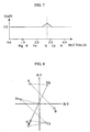
- the hue calculating circuit 101 calculates for each pixel a hue value C_Phase, as shown in Fig. 5, on the basis of the color difference signals (R-Y) and (B-Y) .
- the hue value C_Phase is found as values 0.0 to 4.0 corresponding to an angle centered at the origin on a color difference signal plane, as shown in Fig. 5. Consequently, the hue value C_Phase is a value corresponding to the ratio of the color difference signals (R-Y)/(B-Y) (more specifically, tan -1 ⁇ (R-Y)/(B-Y) ⁇ ).
- the hue calculating circuit 101 comprises a first bit shift circuit 111 to which the color difference signal (R-Y) is inputted, a second bit shift circuit 112 to which the color difference signal (B-Y) is inputted, and a ROM 113, as shown in Fig. 6.
- the two bit shift circuits 111 and 112 are provided in order to cut the number of bits composing an 8-bit input signal to five. That is, each of the bit shift circuits 111 and 112 performs bit shifting, described below.
- the 5-bit color difference signal (R-Y) and the 5-bit color difference signal (B-Y) which are inputted are inputted to the ROM 113.
- the ROM 113 outputs for each pixel a hue value C_Phase corresponding to the values of the input color difference signals (R-Y) and (B-Y) on the basis of a hue conversion table previously stored.
- the saturation calculating circuit 102 calculates for each pixel saturation on the basis of the color difference signals (R-Y) and (B-Y).
- the saturation calculating circuit 102 calculates for each pixel saturation corresponding to the magnitude of each of the input color difference signals (R-Y) and (B-Y) on the basis of a saturation conversion table previously stored.
- the gain correcting circuit 103 comprises a multiplier 121 for adjusting the gain of the luminance signal Y, a multiplier 122 for adjusting the gain of the color difference signal (R-Y), a multiplier 123 for adjusting the gain of the color difference signal (B-Y), a gain calculation register 124, and two selecting circuits (SEL) 125 and 126.
- a gain for each hue value is set by a user in order to adjust the saturation of a particular hue and adjust the lightness of the particular hue. That is, the gain is set at intervals of 0.25 for the hue values 0.0 to 4.0 in the gain calculation register 124.
- the gain calculation register 124 calculates for each pixel a gain corresponding to the hue value C_Phase sent from the hue calculating circuit 101, and outputs the calculated gain. Gains are set at intervals of 0.25 for the hue values 0.0 to 4.0 in the gain calculation register 124.
- the gain calculation register 124 linearly interpolates the gains for the two hue values, thereby calculating the gain for the inputted hue value C_Phase and outputting the calculated gain.
- the gain calculated for each pixel by the gain calculation register 124 is sent to the first selecting circuit 125 and the second selecting circuit 126.
- the first selecting circuit 125 selects the gain or "1" calculated by the gain calculation register 124, and sends the selected gain or "1” to the multipliers 122 and 123.
- the second selecting circuit 126 selects the gain or "1” calculated by the gain calculation register 124, and sends the selected gain or "1” to the multiplier 121.
- the first selecting circuit 125 is controlled such that the gain calculated by the gain calculation register 124 is selected.
- the second selecting circuit 126 is controlled such that the gain calculated by the gain calculation register 124 is selected.
- the gain calculated by the gain calculation register 124 through the second selecting circuit 126 is sent to the multiplier 121, the gain of the luminance signal Y against the hue of green is raised. Accordingly, the lightness of green is increased.
- the hue correcting circuit 104 comprises an R-Y offset calculation register 131, a B-Y offset calculation register 132, a multiplier 133 for multiplying saturation calculated by the saturation calculating circuit 102 by an offset outputted from the R-Y offset calculation register 131, a multiplier 134 for multiplying the saturation calculated by the saturation calculating circuit 102 by an offset outputted from the B-Y offset calculation register 132, an adder 135 for adding an offset outputted from the multiplier 133 to the color difference signal (R-Y) outputted from the gain correcting circuit 103, and an adder 136 for adding an offset outputted from the multiplier 134 to the color difference signal (BY) outputted from the gain correcting circuit 103.
- the offset for each hue value is set by the user, in order to correct the hue for only the particular hue, in each of the R-Y offset calculation register 131 and the B-Y offset calculation register 132. That is, the offset is set at intervals of 0.25 against the hue values 0.0 to 4.0 in each of the offset calculation registers 131 and 132.
- the offset for each hue value is set in each of the offset calculation registers 131 and 132.
- R-Y indicates the offset for each hue value set in the R-Y offset calculation register 131
- B-Y indicates the offset for each hue value set in the B-Y offset calculation register 132.
- Each of the offset calculation registers 131 and 132 calculates for each pixel an offset corresponding to the hue value C_Phase sent from the hue calculating circuit 101, and outputs the calculated offset. Offsets are set at intervals of 0.25 for the hue values 0.0 to 4.0 in each of the offset calculation registers 131 and 132.
- the hue value C_Phase sent from the hue calculating circuit 101 is a value between the two hue values for which the offsets are respectively set, therefore, each of the offset calculation registers 131 and 132 linearly interpolates the offsets for the two hue values, thereby calculating the offset for the inputted hue value C_Phase and outputting the calculated offset.
- the offset calculated for each pixel by the R-Y offset calculation register 131 is sent to the multiplier 133, and is multiplied by the saturation calculated by the saturation calculating circuit 102. Consequently, the R-Y offset corresponding to the saturation is obtained for each pixel.
- the offset for each pixel calculated by the R-Y offset calculation register 132 is sent to the multiplier 134, and is multiplied by the saturation calculated by the saturation calculating circuit 102. Consequently, the B-Y offset corresponding to the saturation is obtained for each pixel.
- the R-Y offset outputted from the multiplier 133 is sent to the adder 135, and is added to the color difference signal (R-Y) outputted from the gain correcting circuit 103.
- the B-Y offset outputted from the multiplier 134 is sent to the adder 136, and is added to the color difference signal (B-Y) outputted from the gain correction circuit 103.
- the offset is provided to the color difference signal (R-Y) corresponding to the hue of green such that the magnitude thereof is decreased, and the offset is provided to the color difference signal (B-Y) corresponding to the hue of green such that the magnitude thereof is increased. Consequently, the hue of green is moved toward Ye, as shown in Fig. 10.
- the present invention is also applicable to video display devices such as a television receiver, a VTR, and a liquid crystal projector.
- the tone can be corrected only for the arbitrary hue.
- the hue can be corrected only for the arbitrary hue.
- Fig. 11 illustrates the configuration of a color collecting circuit in a single plate type color camera.
- the color correcting circuit is provided in the succeeding stage of the color difference matrix circuit 5 shown in Fig. 1.
- the color correcting circuit comprises a color region judging unit 201, a color selecting unit 202, a vector decomposing unit 203, a first vector converting unit 204, a second vector converting unit 205, and a vector synthesizing unit 206.
- Input color difference signals (B-Y) and (R-Y) are inputted to the color region judging unit 201, and coordinate values on a color difference signal plane of R, G, and B colors are inputted thereto.
- Fig. 12 illustrates a color difference signal plane where the color difference signal (B-Y) and the color difference signal (R-Y) are respectively used to enter the X-axis and the Y-axis.
- the color difference signal plane six triangular regions each formed by the origin and two adjacent ones of the vertexes Mg, R, Ye, G, Cy, and B of a hexagon are respectively taken as S1, S2, S3, S4, S5, and S6.
- the range of a hue is divided into six regions S1 to S6 by three division axes, i.e., a Ye-B axis, a Cy-R axis, and an Mg-G axis.
- the color region judging unit 201 judges for each pixel to which of the regions S1 to S6 the hue of the input color difference signal belongs on the basis of the color difference signals (R-Y) and (B-Y) inputted for each pixel. The judging method will be described.
- a, b, and c be respectively position vectors for B, R and G colors, as shown in Fig. 13, the vectors a, b, and c can be expressed by the following equation (2) using the coordinate values (ax, ay), (bx, by), and (cx, cy) of B, R, and G colors:
- S7 indicates the origin.
- S8 indicates that there is no region.
- + includes zero.
- the results of the judgment by the color region judging unit 201 are inputted to the color selecting unit 202, and the coordinate values on the color difference signal plane of R, G, B, Mg, Cy, and Ye colors and a transform matrix for one, corresponding to a region where the color is changed, of the R, G, B, Mg, Cy, and Ye axes are inputted thereto.
- the color selecting unit 202 respectively selects and outputs the coordinate values of the colors B and Mg corresponding to the two axes (the first axis and the second axis) for defining the region S1 and the transform matrices corresponding to the axes.
- the coordinate values of the colors B and Mg outputted from the color selecting unit 202 are sent to the vector decomposing unit 203.
- the coordinate value of the color B outputted from the color selecting unit 202 and the transform matrix corresponding to the B axis are sent to the first vector converting unit 204.
- the coordinate value of the color Mg outputted from the color selecting unit 202 and the transform matrix corresponding to the Mg axis are sent to the second vector converting unit 205.
- the position vector p of the input color difference signal whose hue is judged to be within the region S1 is decomposed into vector components in directions (a and b directions) of the two axes (two axes adjacent to the position vector p) for designating the region S1. That is, it is assumed that the position vector p of the input color difference signal is decomposed into vector components corresponding to an axis in a direction of c and an axis in a direction a, as shown in Fig. 14.
- vectors corresponding to the two axes vectors directed toward the six vertexes Mg, R, Ye, G, Cy, and B of the hexagon from the origin are used.
- the vector decomposing unit 203 calculates sx, sy, tx, and ty from the coordinate values of the colors B and Mg sent from the color selecting unit 202. Further, the vector decomposing unit 203 calculates px and py from the input color difference signal. The coefficients ⁇ and ⁇ are found on the basis of the foregoing equation (7). The coefficients ⁇ and ⁇ found by the vector decomposing unit 203 are sent to the vector synthesizing unit 206.
- the first vector converting unit 204 calculates sx and sy on the basis of the coordinate value of the color B sent from the color selecting unit 202.
- the second vector converting unit 205 calculates tx and ty on the basis of the coordinate value of the color Mg sent from the color selecting unit 202.
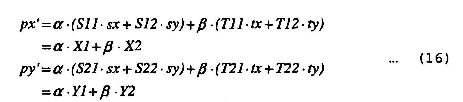
- (T11 ⁇ tx + T12 ⁇ ty) X2
- X1 and Y1 calculated by the first vector converting unit 204 and X2 and Y2 calculated by the second vector converting unit 205 are sent to the vector synthesizing unit 206.
- the vector synthesizing unit 206 calculates and outputs px' (the color difference signal (B-Y) after the change) and py' (the color difference signal (R-Y) after the change) on the basis of the coefficients ⁇ and ⁇ calculated by the vector decomposing unit 203, X1 and Y1 calculated by the first vector converting unit 204, and X2 and Y2 calculated by the second vector converting unit 205, and the foregoing equation (11).
- the color (the position vector p') after the conversion is as shown in Fig. 15, for example.
- the color in the region S1 is corrected toward the region S2. That is, the color in the region S1 can be changed by changing the coefficients in the transform matrices S and T.
- the color in the other region can be also similarly changed.
- the color region judging unit 201 calculates the respective inner products of the position vector p of the input color difference signal and the vectors a', b', and c', and judges to which of the regions S1 to S6 the hue of the input color difference signal belongs by the respective signs of the inner products.
- the inner products are expressed by the following mathematical expression (12), as expressed by the foregoing equation (4):
- the position vector p of the input color difference signal is decomposed into the vector components in the directions of the two axes (two axes adjacent to the position vector p) for defining the region including the vector p (S1 in the example shown in Fig. 14), as shown in Fig. 14.
- K is a constant determined for each of the regions S1 to S6.
- the amount of operation processing of the numerators ⁇ ' and ⁇ ' of ⁇ and ⁇ is reduced by utilizing the inner product calculated in region judgment, and the amount of operation processing of the denominators of ⁇ and ⁇ is reduced by using K previously found for each of the regions.
- the coordinates (corresponding to Ss and Tt) after the conversion of the two axes s and t with the position vector p interposed therebetween are previously determined, thereby eliminating the necessity of a matrix operation for calculating X1, X2, Y1, and Y2.
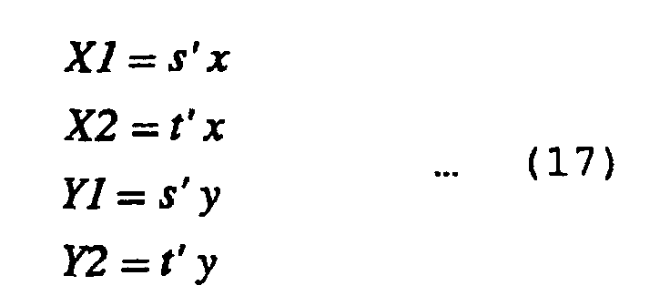
- s' and t' be respectively the coordinates after the conversion of the two axes s and t with the position vector p interposed therebetween, s'x be the x component of s', s'y be the y component of s', t'x be the x component of t', and t'y be the y component of t', X1, X2, Y1, and Y2 are found by the following equation (17):
- Fig. 16 illustrates the configuration of a color correcting circuit in a single plate type color camera.
- the color correcting circuit comprises a color region operating unit 301, a ⁇ ' and ⁇ ' selecting unit 302 for producing ⁇ ' and ⁇ ', a K selecting unit 303 for producing K, a coordinate selecting unit 304 for producing X1, X2, Y1, and Y2, and a converted coordinate operating unit 305.
- the color region operating unit 301 calculates the respective inner products of a position vector p of an input color difference signal and vectors a', b', and c', and judges to which of regions S1 to S6 the hue of the input color difference signal belongs by the respective signs of the inner products, similarly to the color region judging unit 201 shown in Fig. 11.
- the color region operating unit 301 outputs region information which is the results of the region judgment, and outputs the inner product values p ⁇ a', p ⁇ b', and p ⁇ c' of the position vector p used for the region judgment and the vectors a', b', and c'.
- the region information outputted from the color region operating unit 301 is fed to the ⁇ ' and ⁇ ' selecting unit 302, the K selecting unit 303, and the coordinate selecting unit 304.
- the inner product values p ⁇ a', p ⁇ b', and p ⁇ c' outputted from the color region operating unit 301 are fed to the ⁇ ' and ⁇ ' selecting unit 302.
- the ⁇ ' and ⁇ ' selecting unit 302 outputs ⁇ ' and ⁇ ' on the basis of the region information inputted from the color region operating unit 301 and the inner product values p ⁇ a', p ⁇ b', and p ⁇ c'.
- the K selecting unit 303 selects, out of the values of K previously found for the regions S1 to S8, K corresponding to the region information inputted from the color region operating unit 301, and outputs the selected K.
- Coordinates after conversion corresponding to R, G, B, Mg, Cy, and Ye axes taking the origin of a color difference signal plane as its base point are given to the coordinate selecting unit 304.
- the coordinate selecting unit 304 outputs X1, X2, Y1, and Y2 on the basis of the coordinates after conversion corresponding to the two axes for defining a region represented by the region information inputted from the color region operating unit 301.
- the converted coordinate operating unit 305 finds the color (the position vector p') after conversion on the basis of ⁇ ' and ⁇ ' sent from the ⁇ ' and ⁇ ' selecting unit 302, K sent from the K selecting unit 303, and X1, X2, Y1, and Y2 sent from the coordinate selecting unit 304.
- ⁇ and ⁇ are first found on the basis of the following equation (18): px' (a color difference signal (B-Y) after change) and py' (a color difference signal (R-Y) after change) are calculated and outputted on the basis of the following equation (19):
- the present invention is also applicable to video display devices such as a television receiver, a VTR, and a liquid crystal projector.
Abstract
There are provided hue detecting means for detecting a
hue component for each pixel from a first color difference
signal R-Y and a second color difference signal B-Y, and gain
controlling means for controlling for each pixel a gain for
arbitrarily selected one of or an arbitrary combination of a
luminance signal, a first color difference signal R-Y, and a
second color difference signal B-Y depending on the detected
hue component for each pixel.
Description
- The present invention relates to a tone correcting circuit, a hue correcting circuit, and a color correcting circuit.
- Fig. 1 illustrates the configuration of a conventional signal processing circuit in a single plate-type CCD color camera.
- A first
1H delay circuit 1 generates a video signal obtained by delaying an input video signal (a CCD output signal) by 1H (one horizontal period). A second1H delay circuit 2 generates a video signal obtained by further delaying by 1H the video signal delayed by 1H. - The input video signal, the video signal delayed by 1H, and the signal delayed by 2H are fed to a YC separating circuit 3. A luminance signal Yh, a vertical contour signal Vap, a G signal, an R signal, and a B signal are outputted from the YC separating circuit 3.
- The luminance signal Yh and the vertical contour signal Vap are fed to a
Y process circuit 4, are subjected to predetermined luminance signal processing, and are then outputted as a luminance signal Yout. - The G signal, the R signal, and the B signal are fed to a color
difference matrix circuit 5. The colordifference matrix circuit 5 comprises fouradders multipliers matrix coefficient register 25 for giving a multiplication coefficient to each of themultipliers multipliers matrix coefficient register 25 by a CPU 7. - Letting KRRY, KRBY, KBRY, and KBBY be respectively the multiplication coefficients given to the
multipliers difference matrix circuit 5 performs an operation expressed by the following equation (1), to generate color difference signals (R-Y) and (B-Y).
- The color difference signals (R-Y) and (B-Y) obtained by the color
difference matrix circuit 5 are fed to acolor encoding circuit 6. - In the
color encoding circuit 6, two color carriers between which there is a phase difference of 90 degrees are respectively modulated by the color difference signals (R-Y) and (B-Y), and are synthesized, to generate a chrominance signal Cout. - In the above-mentioned circuit, the tone of a video output can be adjusted by changing the coefficients KRRY, KRBY, KBRY, and KBBY in the color
difference matrix circuit 5. That is, a gain in an R-Y direction, a hue (HUE) corresponding to a B-Y axis, a hue (HUE) corresponding to an R-Y axis, and a gain in a B-Y direction are respectively adjusted by the coefficients KRRY, KBRY, KRBY, and KBBY, as shown in Figs. 2a, 2b, 2c, and 2d. - Meanwhile, in the case of the single plate type CCD color camera, a color filter is arranged on a front surface of a CCD. Particularly when a complementary color filter is used as the color filter, it is difficult to change the spectral-response characteristics of Ye, Mg, Cy, and G color filters to ideal characteristics. Accordingly, a color different from the inherent color is reproduced.
- For example, green-based colors are not easily obtained, blue-based colors are predominantly obtained, and red-based colors are shifted in a magenta direction. It is difficult to adjust such degradation of color reproducibility only by the coefficients KRRY, KRBY, KBRY, and KBBY in the color
difference matrix circuit 5. The reason for this is that in a case where green-based colors are insufficient, for example, when the coefficient KRRY is increased, green can be heightened, while cyan, red, and magenta are also similarly heightened. - An object of the present invention is to provide a tone correcting circuit capable of correcting a tone only for an arbitrary hue.
- Another object of the present invention is to provide a hue correcting circuit capable of correcting a hue only for an arbitrary hue.
- Still another object of the present invention is to provide a color correcting circuit capable of correcting a color only for a hue within an arbitrary range out of all hue ranges.
- A tone correcting circuit according to the present invention is characterized by comprising hue detecting means for detecting a hue component for each pixel from a first color difference signal R-Y and a second color difference signal B-Y; and gain controlling means for controlling for each pixel a gain for arbitrarily selected one of or an arbitrary combination of a luminance signal, a first color difference signal R-Y, and a second color difference signal B-Y depending on the detected hue component for each pixel, thereby correcting a tone only for an arbitrary hue.
- A gain is set for each hue. An example of the gain controlling means is one comprising gain calculating means for calculating for each pixel the gain corresponding to the hue component for each pixel detected by the hue detecting means on the basis of the set gain for each hue, and means for providing for each pixel the gain for the pixel calculated by the gain calculating means as the gain for arbitrarily selected one of or the arbitrary combination of the luminance signal, the first color difference signal R-Y, and the second color difference signal B-Y.
- An example of the hue detecting means is one comprising a first bit shift circuit to which the first color difference signal (R-Y) is inputted, a second bit shift circuit to which a second color difference signal (B-Y) is inputted, and means for outputting for each pixel hue values corresponding to output values of both the bit shift circuits as hue components on the basis of a look-up table, each of the bit shift circuits cutting the number of bits composing an n-bit input signal to m which is smaller than n, cutting, when at least the respective uppermost bits in the color difference signals are both zero, the upper x bits in each of the color difference signals, letting x be the smaller one of the number of bits, out of the bits from the uppermost bit to the (m+1)-th bit in one of the color difference signals, which are continuously zero from the uppermost bit and the number of bits, out of the bits from the uppermost bit to the (m+1)-th bit in the other color difference signal, which are continuously zero from the uppermost bit, and further cutting the lower (n-m-x) bits in each of the color difference signals when x is smaller than (n-m).
- A hue correcting circuit according to the present invention is characterized by comprising hue detecting means for detecting a hue component for each pixel from a first color difference signal R-Y and a second color difference signal B-Y; first offset providing means for providing an offset for each pixel to the first color difference signal R-Y depending on the detected hue component for each pixel; and second offset providing means for providing an offset for each pixel to the second color difference signal B-Y, thereby correcting a hue only for an arbitrary hue.
- An offset is set for each hue. An example of each of the offset providing means is one comprising saturation detecting means for detecting saturation for each pixel from the first color difference signal R-Y and the second color difference signal B-Y, offset calculating means for calculating for each pixel an offset corresponding to the hue component for each pixel detected by the hue detecting means on the basis of the set offset for each hue, offset producing means for multiplying the offset for each pixel calculated by the offset calculating means by the saturation of the corresponding pixel detected by the saturation detecting means, to produce for each pixel the offset corresponding to the saturation, and means for providing for each pixel the offset for each pixel produced by the offset producing means to the color difference signal.
- An example of the hue detecting means is one comprising a first bit shift circuit to which the first color difference signal (R-Y) is inputted, a second bit shift circuit to which a second color difference signal (B-Y) is inputted, and means for outputting for each pixel hue values corresponding to output values of both the bit shift circuits as hue components on the basis of a look-up table, each of the bit shift circuits cutting the number of bits composing an n-bit input signal to m which is smaller than n, cutting, when at least the respective uppermost bits in the color difference signals are both zero, the upper x bits in each of the color difference signals, letting x be the smaller one of the number of bits, out of the bits from the uppermost bit to the (m+1)-th bit in one of the color difference signals, which are continuously zero from the uppermost bit and the number of bits, out of the bits from the uppermost bit to the (m+1)-th bit in the other color difference signal, which are continuously zero from the uppermost bit, and further cutting the lower (n-m-x) bits in each of the color difference signals when x is smaller than (n-m).
- A first color correcting circuit according to the present invention is characterized in that within a color difference signal plane, the range of a hue is divided into a plurality of regions by at least two division axes passing through the origin, and by comprising judging means for judging, on the basis of input color difference signals R-Y and B-Y, to which of the regions the hue of the input color difference signal belongs, and color difference signal converting means for subjecting the input color difference signal whose hue is judged to belong to the predetermined region to color difference signal conversion processing, the color difference signal converting means comprising coefficient calculating means for calculating, in a case where a position vector of the input color difference signal whose hue is judged to belong to the predetermined region is decomposed into vector components corresponding to the two adjacent division axes, the coefficient of each of the vector components, and means for respectively primarily converting the vectors corresponding to the two division axes by a transform matrix previously set, to convert the input color difference signal on the basis of the vectors corresponding to the two axes after the primary conversion and the coefficients calculated by the coefficient calculation means.
- A second color correcting circuit according to the present invention is characterized in that within a color difference signal plane, the range of a hue is divided into a plurality of regions by at least two division axes passing through the origin, and by comprising judging means for judging, on the basis of input color difference signals R-Y and B-Y, to which of the regions the hue of the input color difference signal belongs, and color difference signal converting means for subjecting the input color difference signal whose hue is judged to belong to the predetermined region to color difference signal conversion processing, the color difference signal converting means comprising coefficient calculating means for calculating, in a case where it is assumed that a position vector of the input color difference signal whose hue is judged to belong to the predetermined region is decomposed into vector components corresponding to the two adjacent division axes, the coefficient of each of the vector components, and means for converting the input color difference signal on the basis of vectors corresponding to the two axes after the conversion, which have been previously set for the vector components corresponding to the two division axes and the coefficients calculated by the coefficient calculating means.
- The range of the hue is divided into six regions by three division axes comprising a Ye-B axis, a Cy-R axis, and an Mg-G axis within the color difference signal plane. An example of the judging means is one for judging to which of the regions the hue of the input color difference signal belongs on the basis of the input color difference signals R-Y and B-Y.
- An example of the judging means is one comprising means for operating the respective inner products of vectors respectively perpendicular to the vectors corresponding to the division axes and the position vector of the input color difference signal, and means for judging to which of the regions the hue of the input color difference signal belongs on the basis of the respective signs of the inner products.
-
- Fig. 1 is a block diagram showing the configuration of a conventional signal processing circuit in a single plate type CCD color camera.
- Figs. 2a to 2d are schematic views for explaining that the tone of a video output can be adjusted by changing coefficients KRRY, KRBY, KBRY, and KBBY in a color difference matrix circuit.
- Fig. 3 is a block diagram showing the configuration of a signal processing circuit in a single plate type CCD color camera.
- Fig. 4 is a block diagram showing the configuration of a tone and hue correcting circuit.
- Fig. 5 is a schematic view showing a hue value C_Phase calculated by a hue calculating circuit.
- Fig. 6 is a block diagram showing the configuration of a hue calculating circuit.
- Fig. 7 is a graph showing a gain for each hue value set in a gain calculation register in a case where it is desired to emphasize only green.
- Fig. 8 is a schematic view showing that the saturation of green is increased in a case where a gain for each hue value as shown in Fig. 7 is set in a gain calculation register.
- Fig. 9 is a graph showing an offset for each hue value set in each offset calculation register in a case where it is desired to correct the hue of green toward Ye.
- Fig. 10 is a schematic view showing that the hue of green is corrected toward Ye in a case where an offset for each hue value as shown in Fig. 9 is set in an offset calculation register.
- Fig. 11 is a block diagram showing the configuration of a color correcting circuit.
- Fig. 12 is a schematic view showing a color difference signal plane where a color difference signal (B-Y) and a color difference signal (R-Y) are respectively used to enter the X-axis and the Y-axis.
- Fig. 13 is a schematic view showing position vectors a, b, and c for B, R, and G colors and vectors a', b', and c' perpendicular thereto.
- Fig. 14 is a schematic view showing how a position vector p of an input color difference signal is decomposed into vector components in directions corresponding to two axes adjacent to the position vector p.
- Fig. 15 is a schematic view showing a color (a position vector p') after conversion.
- Fig. 16 is a block diagram showing another example of a color correcting circuit.
-
- Description is now made of embodiments in a case where the present invention is applied to a single plate type color camera.
- Referring to Figs. 3 to 10, a first embodiment of the present invention will be described.
- Fig. 3 illustrates the configuration of a signal processing circuit in a single plate type CCD color camera. In Fig. 3, the same components as those shown in Fig. 1 are assigned the same reference numerals and hence, the description thereof is not repeated. In the signal processing circuit, a tone and
hue correcting circuit 100 is added to the signal processing circuit shown in Fig. 1. - Fig. 4 illustrates the configuration of the tone and
hue correcting circuit 100. - A luminance signal Y outputted from a
Y process circuit 4 and color difference signals (R-Y) and (B-Y) outputted from a colordifference matrix circuit 5 are inputted to the tone andhue correcting circuit 100. - The tone and
hue correcting circuit 100 comprises ahue calculating circuit 101, asaturation calculating circuit 102 for calculating saturation on the basis of the color difference signals (R-Y) and (B-Y), a gain correcting circuit (a tone correcting circuit) 103, and ahue correcting circuit 104. - The
hue calculating circuit 101 calculates for each pixel a hue value C_Phase, as shown in Fig. 5, on the basis of the color difference signals (R-Y) and (B-Y) . The hue value C_Phase is found as values 0.0 to 4.0 corresponding to an angle centered at the origin on a color difference signal plane, as shown in Fig. 5. Consequently, the hue value C_Phase is a value corresponding to the ratio of the color difference signals (R-Y)/(B-Y) (more specifically, tan-1{(R-Y)/(B-Y)}). - The
hue calculating circuit 101 comprises a firstbit shift circuit 111 to which the color difference signal (R-Y) is inputted, a secondbit shift circuit 112 to which the color difference signal (B-Y) is inputted, and aROM 113, as shown in Fig. 6. - The two
bit shift circuits bit shift circuits - (1) When the upper three bits in each of the color difference signals (R-Y) and (B-Y) are zero, the bit shifting is performed such that the upper three bits are cut.
- (2) When the upper two bits in each of the color difference signals (R-Y) and (B-Y) are zero, the bit shifting is performed such that the upper two bits are cut, and the lower one bit is rounded down (cut).
- (3) When the upper one bit in each of the color difference signals (R-Y) and (B-Y) is zero, the bit shifting is performed such that the upper one bit is cut, and the lower two bits are rounded down (cut).
- (4) In a case which does not correspond to the foregoing items (1) to (3), the bit shifting is performed such that the lower three bits in each of the color difference signals (R-Y) and (B-Y) are rounded down (cut).
-
- The 5-bit color difference signal (R-Y) and the 5-bit color difference signal (B-Y) which are inputted are inputted to the
ROM 113. TheROM 113 outputs for each pixel a hue value C_Phase corresponding to the values of the input color difference signals (R-Y) and (B-Y) on the basis of a hue conversion table previously stored. - The
saturation calculating circuit 102 calculates for each pixel saturation on the basis of the color difference signals (R-Y) and (B-Y). Thesaturation calculating circuit 102 calculates for each pixel saturation corresponding to the magnitude of each of the input color difference signals (R-Y) and (B-Y) on the basis of a saturation conversion table previously stored. - The
gain correcting circuit 103 comprises amultiplier 121 for adjusting the gain of the luminance signal Y, amultiplier 122 for adjusting the gain of the color difference signal (R-Y), amultiplier 123 for adjusting the gain of the color difference signal (B-Y), again calculation register 124, and two selecting circuits (SEL) 125 and 126. - In the
gain calculation register 124, a gain for each hue value is set by a user in order to adjust the saturation of a particular hue and adjust the lightness of the particular hue. That is, the gain is set at intervals of 0.25 for the hue values 0.0 to 4.0 in thegain calculation register 124. - In cases such as a case where it is desired to only emphasize green (a case where it is desired to increase the concentration of green) and a case where it is desired to brighten only green, such gains for each hue value that the gain against only the hue of green (the vicinity of the hue value 2.75) is increased are set in the
gain calculation register 124, as shown in Fig. 7. - The
gain calculation register 124 calculates for each pixel a gain corresponding to the hue value C_Phase sent from thehue calculating circuit 101, and outputs the calculated gain. Gains are set at intervals of 0.25 for the hue values 0.0 to 4.0 in thegain calculation register 124. When the hue value C_Phase sent from thehue calculating circuit 101 is a value between the two hue values for which the gains are respectively set, therefore, thegain calculation register 124 linearly interpolates the gains for the two hue values, thereby calculating the gain for the inputted hue value C_Phase and outputting the calculated gain. - The gain calculated for each pixel by the
gain calculation register 124 is sent to the first selectingcircuit 125 and the second selectingcircuit 126. The first selectingcircuit 125 selects the gain or "1" calculated by thegain calculation register 124, and sends the selected gain or "1" to themultipliers circuit 126 selects the gain or "1" calculated by thegain calculation register 124, and sends the selected gain or "1" to themultiplier 121. - When the concentration of the particular hue is adjusted, the first selecting
circuit 125 is controlled such that the gain calculated by thegain calculation register 124 is selected. When the brightness of the particular hue is adjusted, the second selectingcircuit 126 is controlled such that the gain calculated by thegain calculation register 124 is selected. - In a case where such gains that the gain against only the hue of green is increased are set, as shown in Fig. 7, in the
gain calculation register 124, for example, suppose a case where the gain calculated by thegain calculation register 124 through the first selectingcircuit 125 is sent to themultipliers - Furthermore, when the gain calculated by the
gain calculation register 124 through the second selectingcircuit 126 is sent to themultiplier 121, the gain of the luminance signal Y against the hue of green is raised. Accordingly, the lightness of green is increased. - The
hue correcting circuit 104 comprises an R-Y offsetcalculation register 131, a B-Y offsetcalculation register 132, amultiplier 133 for multiplying saturation calculated by thesaturation calculating circuit 102 by an offset outputted from the R-Y offsetcalculation register 131, amultiplier 134 for multiplying the saturation calculated by thesaturation calculating circuit 102 by an offset outputted from the B-Y offsetcalculation register 132, an adder 135 for adding an offset outputted from themultiplier 133 to the color difference signal (R-Y) outputted from thegain correcting circuit 103, and anadder 136 for adding an offset outputted from themultiplier 134 to the color difference signal (BY) outputted from thegain correcting circuit 103. - The offset for each hue value is set by the user, in order to correct the hue for only the particular hue, in each of the R-Y offset
calculation register 131 and the B-Y offsetcalculation register 132. That is, the offset is set at intervals of 0.25 against the hue values 0.0 to 4.0 in each of the offset calculation registers 131 and 132. - In a case where it is desired to correct the hue of green toward Ye, for example, the offset for each hue value, as shown in Fig. 9, is set in each of the offset calculation registers 131 and 132. In Fig. 9, R-Y indicates the offset for each hue value set in the R-Y offset
calculation register 131, and B-Y indicates the offset for each hue value set in the B-Y offsetcalculation register 132. - Each of the offset calculation registers 131 and 132 calculates for each pixel an offset corresponding to the hue value C_Phase sent from the
hue calculating circuit 101, and outputs the calculated offset. Offsets are set at intervals of 0.25 for the hue values 0.0 to 4.0 in each of the offset calculation registers 131 and 132. When the hue value C_Phase sent from thehue calculating circuit 101 is a value between the two hue values for which the offsets are respectively set, therefore, each of the offset calculation registers 131 and 132 linearly interpolates the offsets for the two hue values, thereby calculating the offset for the inputted hue value C_Phase and outputting the calculated offset. - The offset calculated for each pixel by the R-Y offset
calculation register 131 is sent to themultiplier 133, and is multiplied by the saturation calculated by thesaturation calculating circuit 102. Consequently, the R-Y offset corresponding to the saturation is obtained for each pixel. Similarly, the offset for each pixel calculated by the R-Y offsetcalculation register 132 is sent to themultiplier 134, and is multiplied by the saturation calculated by thesaturation calculating circuit 102. Consequently, the B-Y offset corresponding to the saturation is obtained for each pixel. - The R-Y offset outputted from the
multiplier 133 is sent to the adder 135, and is added to the color difference signal (R-Y) outputted from thegain correcting circuit 103. Similarly, the B-Y offset outputted from themultiplier 134 is sent to theadder 136, and is added to the color difference signal (B-Y) outputted from thegain correction circuit 103. - When an offset for correcting the hue of green toward Ye is set, as shown in Fig. 9, in each of the offset calculation registers 131 and 132, for example, the offset is provided to the color difference signal (R-Y) corresponding to the hue of green such that the magnitude thereof is decreased, and the offset is provided to the color difference signal (B-Y) corresponding to the hue of green such that the magnitude thereof is increased. Consequently, the hue of green is moved toward Ye, as shown in Fig. 10.
- Although in the above-mentioned first embodiment, description was made of a case where the saturation, lightness, and hue are adjusted for the hue of green, it goes without saying that the saturation, lightness, and hue can be also similarly adjusted for another arbitrary hue.
- Although in the above-mentioned first embodiment, description was made of a case where the present invention is applied to the single plate type color camera, the present invention is also applicable to video display devices such as a television receiver, a VTR, and a liquid crystal projector.
- According to the above-mentioned first embodiment, the tone can be corrected only for the arbitrary hue. Further, according to the above-mentioned first embodiment, the hue can be corrected only for the arbitrary hue.
- Referring to Figs. 11 to 15, a second embodiment of the present invention will be described.
- Fig. 11 illustrates the configuration of a color collecting circuit in a single plate type color camera.
- The color correcting circuit is provided in the succeeding stage of the color
difference matrix circuit 5 shown in Fig. 1. The color correcting circuit comprises a colorregion judging unit 201, acolor selecting unit 202, avector decomposing unit 203, a firstvector converting unit 204, a secondvector converting unit 205, and avector synthesizing unit 206. - Description is made of color region judgment processing by the color
region judging unit 201. - Input color difference signals (B-Y) and (R-Y) are inputted to the color
region judging unit 201, and coordinate values on a color difference signal plane of R, G, and B colors are inputted thereto. - Fig. 12 illustrates a color difference signal plane where the color difference signal (B-Y) and the color difference signal (R-Y) are respectively used to enter the X-axis and the Y-axis. Within the color difference signal plane, six triangular regions each formed by the origin and two adjacent ones of the vertexes Mg, R, Ye, G, Cy, and B of a hexagon are respectively taken as S1, S2, S3, S4, S5, and S6.
- In other words, within the color difference signal plane, the range of a hue is divided into six regions S1 to S6 by three division axes, i.e., a Ye-B axis, a Cy-R axis, and an Mg-G axis.
- The color
region judging unit 201 judges for each pixel to which of the regions S1 to S6 the hue of the input color difference signal belongs on the basis of the color difference signals (R-Y) and (B-Y) inputted for each pixel. The judging method will be described. - Letting a, b, and c be respectively position vectors for B, R and G colors, as shown in Fig. 13, the vectors a, b, and c can be expressed by the following equation (2) using the coordinate values (ax, ay), (bx, by), and (cx, cy) of B, R, and G colors:

- Letting a', b', and c' be vectors obtained by rotating the vectors a, b, and c by 90 degrees in a counterclockwise direction, the vectors a', b', and c' are expressed by the following equation (3):

- Let p be a position vector of the input color difference signal. The respective inner products of the position vector p of the input color difference signal and the vectors a', b', and c' are operated on the basis of the following equation (4) :

- It is judged to which of the regions S1 to S6 the hue of the input color difference signal belongs on the basis of the respective signs of the inner products and a region judgment table shown in Table 1.
S1 S2 S3 S4 S5 S6 S7 S8 a' + + + - - - + - b' - - + + + - + - c' + - - - + + + - - In Table 1, S7 indicates the origin. S8 indicates that there is no region. Further, in Table 1, + includes zero.
- The results of the judgment by the color
region judging unit 201 are inputted to thecolor selecting unit 202, and the coordinate values on the color difference signal plane of R, G, B, Mg, Cy, and Ye colors and a transform matrix for one, corresponding to a region where the color is changed, of the R, G, B, Mg, Cy, and Ye axes are inputted thereto. Here, description is made of a case where the color in a region S1 is changed. Consequently, transform matrices corresponding to the two axes B and Mg for defining the region S1 are inputted. - With respect to the input color difference signal whose hue is judged to be within the region S1, the
color selecting unit 202 respectively selects and outputs the coordinate values of the colors B and Mg corresponding to the two axes (the first axis and the second axis) for defining the region S1 and the transform matrices corresponding to the axes. - The coordinate values of the colors B and Mg outputted from the
color selecting unit 202 are sent to thevector decomposing unit 203. The coordinate value of the color B outputted from thecolor selecting unit 202 and the transform matrix corresponding to the B axis are sent to the firstvector converting unit 204. The coordinate value of the color Mg outputted from thecolor selecting unit 202 and the transform matrix corresponding to the Mg axis are sent to the secondvector converting unit 205. - It is assumed that the position vector p of the input color difference signal whose hue is judged to be within the region S1 is decomposed into vector components in directions (a and b directions) of the two axes (two axes adjacent to the position vector p) for designating the region S1. That is, it is assumed that the position vector p of the input color difference signal is decomposed into vector components corresponding to an axis in a direction of c and an axis in a direction a, as shown in Fig. 14. As the vectors corresponding to the two axes, vectors directed toward the six vertexes Mg, R, Ye, G, Cy, and B of the hexagon from the origin are used.
- Letting t be the vector directed toward Mg from the origin (in the opposite direction to c), and letting s be the vector directed toward B from the origin (in the same direction as a), as shown in Fig. 14, p is expressed by the following equation (5):
- Letting px, sx, tx be respectively x components of p, s, and t, and letting py, sy, and ty be respectively y components of p, s, and t, px (= an input color difference signal (B-Y)) and py (= an input color difference signal (R-Y)) are expressed by the following equation (6):

- Consequently, the coefficients α and β are found by the following equation (7) :

- The
vector decomposing unit 203 calculates sx, sy, tx, and ty from the coordinate values of the colors B and Mg sent from thecolor selecting unit 202. Further, thevector decomposing unit 203 calculates px and py from the input color difference signal. The coefficients α and β are found on the basis of the foregoing equation (7). The coefficients α and β found by thevector decomposing unit 203 are sent to thevector synthesizing unit 206. - Before describing the operations of each of the
vector converting units - In order to convert the color (the position vector p) of the input color difference signal, the two axes s and t shown in Fig. 14 are first primarily converted by transform matrices S and T respectively expressed by the following equations (8) and (9) :


- The coefficients in the transform matrices S and T are previously set depending on the contents of the change in the hue in the region S1. Letting Ss and Tt be respectively s and t after the conversion, the color (the position vector p') after the change is expressed by the following equation (10):
- Letting px' be the x component of p' (the color difference signal (B-Y) after the change), and letting py' be the y component of p' (the color difference signal (R-Y) after the change), px' and py' are found by the following equation (11) :

- The first
vector converting unit 204 calculates sx and sy on the basis of the coordinate value of the color B sent from thecolor selecting unit 202. (S11 · sx + S12 · sy) = X1 and (S21 · sx + S22 · sy) = Y1 in the foregoing equation (11) are calculated and outputted on the basis of sx and sy obtained and the transform matrix S corresponding to the B axis sent from thecolor selecting unit 202. - The second
vector converting unit 205 calculates tx and ty on the basis of the coordinate value of the color Mg sent from thecolor selecting unit 202. (T11 · tx + T12 · ty) = X2 and (T21 · tx + T22 · ty) = Y2 in the foregoing equation (11) are calculated and outputted on the basis of tx and ty obtained and the transform matrix T corresponding to the Mg axis sent from thecolor selecting unit 202. - X1 and Y1 calculated by the first
vector converting unit 204 and X2 and Y2 calculated by the secondvector converting unit 205 are sent to thevector synthesizing unit 206. - The
vector synthesizing unit 206 calculates and outputs px' (the color difference signal (B-Y) after the change) and py' (the color difference signal (R-Y) after the change) on the basis of the coefficients α and β calculated by thevector decomposing unit 203, X1 and Y1 calculated by the firstvector converting unit 204, and X2 and Y2 calculated by the secondvector converting unit 205, and the foregoing equation (11). - The color (the position vector p') after the conversion is as shown in Fig. 15, for example. In this example, the color in the region S1 is corrected toward the region S2. That is, the color in the region S1 can be changed by changing the coefficients in the transform matrices S and T. The color in the other region can be also similarly changed.
- Referring to Fig. 16, a third embodiment of the present invention will be described.
- First, description is made of the characteristics of a third embodiment, that is, the difference from the above-mentioned second embodiment. The third embodiment is characterized in two points.
- In the above-mentioned second embodiment, the color
region judging unit 201 calculates the respective inner products of the position vector p of the input color difference signal and the vectors a', b', and c', and judges to which of the regions S1 to S6 the hue of the input color difference signal belongs by the respective signs of the inner products. In this case, the inner products are expressed by the following mathematical expression (12), as expressed by the foregoing equation (4):
- Furthermore, in the above-mentioned second embodiment, the position vector p of the input color difference signal is decomposed into the vector components in the directions of the two axes (two axes adjacent to the position vector p) for defining the region including the vector p (S1 in the example shown in Fig. 14), as shown in Fig. 14.
- In the case, letting s and t be respectively vectors corresponding to the two axes, the position vector p indicates p = α · s + β · t, as expressed by the foregoing equation (5). α and β are expressed by the following equation (13), as expressed by the foregoing equation (7):

- As shown in Fig. 14, when the position vector p is in the region S1, sx = ax, sy = ay, tx = - cx, and ty = - cy. Accordingly, the numerator (α') of α and the numerator (β') of β in the foregoing equation (13) can be deformed, as expressed by the following equation (14):

- Furthermore, the respective reciprocals K of the denominators of α and β in the foregoing equation (13) can be deformed, as expressed by the following equation (15):
- The value of K is a constant determined for each of the regions S1 to S6.
- In the third embodiment, the amount of operation processing of the numerators α' and β' of α and β is reduced by utilizing the inner product calculated in region judgment, and the amount of operation processing of the denominators of α and β is reduced by using K previously found for each of the regions.
- In the above-mentioned second embodiment, when the position vector p shown in Fig. 14 is converted into a position vector p' shown in Fig. 15, vectors s and t corresponding to two axes with the position vector p interposed therebetween are primarily converted using the transform matrices S and T expressed by the equations (8) and (9).
- In this case, the position vector p' after the conversion satisfies p' = α · Ss + β · Tt, as expressed by the foregoing equation (10). Further, x components px' and py' of the position vector p' after the conversion are expressed by the following equation (16), as expressed by the foregoing equation (11):
- In the third embodiment, the coordinates (corresponding to Ss and Tt) after the conversion of the two axes s and t with the position vector p interposed therebetween are previously determined, thereby eliminating the necessity of a matrix operation for calculating X1, X2, Y1, and Y2.
- That is, letting s' and t' be respectively the coordinates after the conversion of the two axes s and t with the position vector p interposed therebetween, s'x be the x component of s', s'y be the y component of s', t'x be the x component of t', and t'y be the y component of t', X1, X2, Y1, and Y2 are found by the following equation (17):
- Fig. 16 illustrates the configuration of a color correcting circuit in a single plate type color camera.
- The color correcting circuit comprises a color
region operating unit 301, a α' and β' selectingunit 302 for producing α' and β', aK selecting unit 303 for producing K, a coordinate selectingunit 304 for producing X1, X2, Y1, and Y2, and a converted coordinateoperating unit 305. - The color
region operating unit 301 calculates the respective inner products of a position vector p of an input color difference signal and vectors a', b', and c', and judges to which of regions S1 to S6 the hue of the input color difference signal belongs by the respective signs of the inner products, similarly to the colorregion judging unit 201 shown in Fig. 11. - The color
region operating unit 301 outputs region information which is the results of the region judgment, and outputs the inner product values p · a', p · b', and p · c' of the position vector p used for the region judgment and the vectors a', b', and c'. - The region information outputted from the color
region operating unit 301 is fed to the α' and β' selectingunit 302, theK selecting unit 303, and the coordinate selectingunit 304. The inner product values p · a', p · b', and p · c' outputted from the colorregion operating unit 301 are fed to the α' and β' selectingunit 302. - The α' and β' selecting
unit 302 outputs α' and β' on the basis of the region information inputted from the colorregion operating unit 301 and the inner product values p · a', p · b', and p · c'. - The relationship between the results of the region judgment represented by the region information and α' and β' outputted from the α' and β' selecting
unit 302 is shown in Table 2:
- The
K selecting unit 303 selects, out of the values of K previously found for the regions S1 to S8, K corresponding to the region information inputted from the colorregion operating unit 301, and outputs the selected K. - The relationship between the results of the region judgment S1 to S8 represented by the region information and K outputted from the
K selecting unit 303 is shown in Table 3.
- Coordinates after conversion corresponding to R, G, B, Mg, Cy, and Ye axes taking the origin of a color difference signal plane as its base point are given to the coordinate selecting
unit 304. The coordinate selectingunit 304 outputs X1, X2, Y1, and Y2 on the basis of the coordinates after conversion corresponding to the two axes for defining a region represented by the region information inputted from the colorregion operating unit 301. - The converted coordinate
operating unit 305 finds the color (the position vector p') after conversion on the basis of α' and β' sent from the α' and β' selectingunit 302, K sent from theK selecting unit 303, and X1, X2, Y1, and Y2 sent from the coordinate selectingunit 304. - That is, α and β are first found on the basis of the following equation (18):px' (a color difference signal (B-Y) after change) and py' (a color difference signal (R-Y) after change) are calculated and outputted on the basis of the following equation (19):


- Although in the above-mentioned second or third embodiment, description was made of a case where the present invention is applied to the single plate type color camera, the present invention is also applicable to video display devices such as a television receiver, a VTR, and a liquid crystal projector.
- According to the above-mentioned second or third embodiment, it is possible to correct, in all the hue ranges, a color only for the hue in the arbitrary range.
Claims (10)
- A tone correcting circuit comprising:hue detecting means for detecting a hue component for each pixel from a first color difference signal R-Y and a second color difference signal B-Y; andgain controlling means for controlling for each pixel a gain for arbitrarily selected one of or an arbitrary combination of a luminance signal, a first color difference signal R-Y, and a second color difference signal B-Y depending on the detected hue component for each pixel, thereby correcting a tone only for an arbitrary hue.
- The tone correcting circuit according to claim 1, wherein a gain is set for each hue,
the gain controlling means comprising
gain calculating means for calculating for each pixel the gain corresponding to the hue component for each pixel detected by the hue detecting means on the basis of the set gain for each hue, and
means for providing for each pixel the gain for the pixel calculated by the gain calculating means as the gain for arbitrarily selected one of or the arbitrary combination of the luminance signal, the first color difference signal R-Y, and the second color difference signal B-Y. - The tone correcting circuit according to either one of claims 1 and 2, wherein
the hue detecting means comprises a first bit shift circuit to which the first color difference signal (R-Y) is inputted, a second bit shift circuit to which a second color difference signal (B-Y) is inputted, and means for outputting for each pixel hue values corresponding to output values of both the bit shift circuits as hue components on the basis of a look-up table,
each of the bit shift circuits cutting the number of bits composing an n-bit input signal to m which is smaller than n, cutting, when at least the respective uppermost bits in the color difference signals are both zero, the upper x bits in each of the color difference signals, letting x be the smaller one of the number of bits, out of the bits from the uppermost bit to the (m+1)-th bit in one of the color difference signals, which are continuously zero from the uppermost bit and the number of bits, out of the bits from the uppermost bit to the (m+1)-th bit in the other color difference signal, which are continuously zero from the uppermost bit, and further cutting the lower (n-m-x) bits in each of the color difference signals when x is smaller than (n-m). - A hue correcting circuit comprising:hue detecting means for detecting a hue component for each pixel from a first color difference signal R-Y and a second color difference signal B-Y;first offset providing means for providing an offset for each pixel to the first color difference signal R-Y depending on the detected hue component for each pixel; andsecond offset providing means for providing an offset for each pixel to the second color difference signal B-Y, thereby correcting a hue only for an arbitrary hue.
- The hue correcting circuit according to claim 4, wherein an offset is set for each hue,
each of the offset providing means comprising
saturation detecting means for detecting saturation for each pixel from the first color difference signal R-Y and the second color difference signal B-Y,
offset calculating means for calculating for each pixel an offset corresponding to the hue component for each pixel detected by the hue detecting means on the basis of the set offset for each hue,
offset producing means for multiplying the offset for each pixel calculated by the offset calculating means by the saturation of the corresponding pixel detected by the saturation detecting means, to produce for each pixel the offset corresponding to the saturation, and
means for providing for each pixel the offset for each pixel produced by the offset producing means to the color difference signal. - The hue correcting circuit according to either one of claims 4 and 5, wherein
the hue detecting means comprises a first bit shift circuit to which the first color difference signal (R-Y) is inputted, a second bit shift circuit to which a second color difference signal (B-Y) is inputted, and means for outputting for each pixel hue values corresponding to output values of both the bit shift circuits as hue components on the basis of a look-up table,
each of the bit shift circuits cutting the number of bits composing an n-bit input signal to m which is smaller than n, cutting, when at least the respective uppermost bits in the color difference signals are both zero, the upper x bits in each of the color difference signals, letting x be the smaller one of the number of bits, out of the bits from the uppermost bit to the (m+1)-th bit in one of the color difference signals, which are continuously zero from the uppermost bit and the number of bits, out of the bits from the uppermost bit to the (m+1)-th bit in the other color difference signal, which are continuously zero from the uppermost bit, and further cutting the lower (n-m-x) bits in each of the color difference signals when x is smaller than (n-m). - A color correcting circuit characterized in that within a color difference signal plane, the range of a hue is divided into a plurality of regions by at least two division axes passing through the origin, and by comprising:judging means for judging, on the basis of input color difference signals R-Y and B-Y, to which of the regions the hue of the input color difference signal belongs, andcolor difference signal converting means for subjecting the input color difference signal whose hue is judged to belong to the predetermined region to color difference signal conversion processing,the color difference signal converting means comprisingcoefficient calculating means for calculating, in a case where it is assumed that a position vector of the input color difference signal whose hue is judged to belong to the predetermined region is decomposed into vector components corresponding to the two adjacent division axes, the coefficient of each of the vector components, andmeans for respectively primarily converting said vectors corresponding to the two division axes by a transform matrix previously set, to convert the input color difference signal on the basis of the vectors corresponding to said two axes after the primary conversion and the coefficients calculated by the coefficient calculation means.
- A color correcting circuit characterized in that within a color difference signal plane, the range of a hue is divided into a plurality of regions by at least two division axes passing through the origin, and by comprising:judging means for judging, on the basis of input color difference signals R-Y and B-Y, to which of the regions the hue of the input color difference signal belongs, andcolor difference signal converting means for subjecting the input color difference signal whose hue is judged to belong to the predetermined region to color difference signal conversion processing,the color difference signal converting means comprisingcoefficient calculating means for calculating, in a case where it is assumed that a position vector of the input color difference signal whose hue is judged to belong to the predetermined region is decomposed into vector components corresponding to the two adjacent division axes, the coefficient of each of the vector components, andmeans for converting the input color difference signal on the basis of vectors corresponding to said two axes after the conversion, which have been previously set for said vector components corresponding to the two division axes and the coefficients calculated by the coefficient calculating means.
- The color correcting circuit according to either one of claims 7 and 8, characterized in that
the range of the hue is divided into six regions by three division axes comprising a Ye-B axis, a Cy-R axis, and an Mg-G axis within the color difference signal plane,
the judging means judging to which of the regions the hue of the input color difference signal belongs on the basis of the input color difference signals R-Y and B-Y. - The color correcting circuit according to any one of claims 7, 8, and 9, characterized in that
the judging means comprises means for operating the respective inner products of vectors respectively perpendicular to the vectors corresponding to the division axes and the position vector of the input color difference signal, and means for judging to which of the regions the hue of the input color difference signal belongs on the basis of the respective signs of the inner products.
Applications Claiming Priority (7)
| Application Number | Priority Date | Filing Date | Title |
|---|---|---|---|
| JP2000282363 | 2000-09-18 | ||
| JP2000282363A JP3634730B2 (en) | 2000-09-18 | 2000-09-18 | Tonal correction circuit and hue correction circuit |
| JP2000292734 | 2000-09-26 | ||
| JP2000292734 | 2000-09-26 | ||
| JP2001083406A JP3568485B2 (en) | 2000-09-18 | 2001-03-22 | Color correction circuit |
| JP2001083406 | 2001-03-22 | ||
| PCT/JP2001/008021 WO2002023917A1 (en) | 2000-09-18 | 2001-09-14 | Tonality correcting circuit and hue correcting circuit |
Publications (2)
| Publication Number | Publication Date |
|---|---|
| EP1324621A1 true EP1324621A1 (en) | 2003-07-02 |
| EP1324621A4 EP1324621A4 (en) | 2006-11-15 |
Family
ID=27344651
Family Applications (1)
| Application Number | Title | Priority Date | Filing Date |
|---|---|---|---|
| EP01967686A Withdrawn EP1324621A4 (en) | 2000-09-18 | 2001-09-14 | Tonality correcting circuit and hue correcting circuit |
Country Status (5)
| Country | Link |
|---|---|
| US (1) | US7215366B2 (en) |
| EP (1) | EP1324621A4 (en) |
| JP (2) | JP3634730B2 (en) |
| KR (1) | KR100834605B1 (en) |
| WO (1) | WO2002023917A1 (en) |
Cited By (5)
| Publication number | Priority date | Publication date | Assignee | Title |
|---|---|---|---|---|
| EP1608183A1 (en) * | 2004-06-14 | 2005-12-21 | Dialog Semiconductor GmbH | Matrix circuit for imaging sensors |
| EP1638343A1 (en) | 2004-09-17 | 2006-03-22 | Nikon Corporation | Image processing apparatus for image tone transformation, image processing program, electronic camera, and image processing method |
| EP1396996A3 (en) * | 2002-08-29 | 2006-09-13 | Samsung Electronics Co., Ltd. | RGB signal saturation adjustment |
| EP1569465A3 (en) * | 2004-02-19 | 2007-01-03 | Sony Corporation | Image processing apparatus, and image processing method |
| US8723995B2 (en) | 2004-05-07 | 2014-05-13 | Youliza, Gehts B.V. Limited Liability Company | Extended dynamic range in color imagers |
Families Citing this family (25)
| Publication number | Priority date | Publication date | Assignee | Title |
|---|---|---|---|---|
| US6788812B1 (en) * | 1999-06-18 | 2004-09-07 | Eastman Kodak Company | Techniques for selective enhancement of a digital image |
| DE10064678C1 (en) * | 2000-12-22 | 2002-07-11 | Kappa Opto Electronics Gmbh | Process for signal improvement in an image sequence recorded with a digital color video camera |
| EP1443456A4 (en) * | 2001-11-05 | 2006-11-02 | Sharp Kk | Color image processing method, color image processor, color display, computer program for implementing the color image processing method |
| JP3620529B2 (en) * | 2002-03-18 | 2005-02-16 | 日本ビクター株式会社 | Video correction apparatus and method, video correction program, and recording medium recording the same |
| JP2004126523A (en) * | 2002-07-31 | 2004-04-22 | Seiko Epson Corp | Electronic circuit, electro-optical device, and electronic apparatus |
| KR100943274B1 (en) * | 2002-12-20 | 2010-02-23 | 삼성전자주식회사 | Color signal correction device and a method, and image processing system using the same and a method thereof |
| JP4446674B2 (en) * | 2003-03-31 | 2010-04-07 | 株式会社メガチップス | Image processing apparatus and imaging apparatus |
| US20050018054A1 (en) * | 2003-07-22 | 2005-01-27 | Akihiro Kato | Chroma compensation circuit and its method |
| WO2005112429A1 (en) * | 2004-05-18 | 2005-11-24 | Acutelogic Corporation | Color correction device, color correction method, and color correction display method |
| KR100621412B1 (en) * | 2004-06-08 | 2006-09-08 | 삼성전자주식회사 | Hue correction apparatus and method thereof |
| US7724949B2 (en) * | 2004-06-10 | 2010-05-25 | Qualcomm Incorporated | Advanced chroma enhancement |
| US7599578B2 (en) * | 2004-09-17 | 2009-10-06 | Nikon Corporation | Apparatus, program, and method for image tone transformation, and electronic camera |
| US7405771B2 (en) * | 2004-10-18 | 2008-07-29 | Mstar Semiconductor Inc. | Method and device for independent color management |
| JP4501634B2 (en) * | 2004-10-29 | 2010-07-14 | 富士フイルム株式会社 | Matrix coefficient determination method and image input apparatus |
| CN1973553B (en) * | 2004-11-25 | 2011-01-12 | 三菱电机株式会社 | Color correction method and color correction device |
| JP2007116237A (en) * | 2005-10-18 | 2007-05-10 | Mitsubishi Electric Corp | Color data conversion apparatus and color data conversion method |
| JP4375325B2 (en) * | 2005-11-18 | 2009-12-02 | カシオ計算機株式会社 | Image processing apparatus, image processing method, and program |
| JP4600301B2 (en) * | 2006-01-16 | 2010-12-15 | ソニー株式会社 | Color difference signal correction method, color difference signal processing circuit using the same, and camera system |
| JP2007208884A (en) * | 2006-02-06 | 2007-08-16 | Matsushita Electric Ind Co Ltd | Digital camera |
| TWI309947B (en) * | 2006-03-22 | 2009-05-11 | Quanta Comp Inc | Image processing apparatus and method of the same |
| US7990427B2 (en) * | 2006-08-21 | 2011-08-02 | Micron Technology, Inc. | Method and apparatus for applying tonal correction to images |
| JP2009225114A (en) * | 2008-03-17 | 2009-10-01 | Ricoh Co Ltd | Image processing device |
| JP2010014843A (en) * | 2008-07-02 | 2010-01-21 | Sony Corp | Display unit |
| CN102271215B (en) * | 2010-06-03 | 2016-05-18 | 鸿富锦精密工业(深圳)有限公司 | The camera of tool image processing function and camera system |
| JP5503497B2 (en) * | 2010-10-26 | 2014-05-28 | パナソニック株式会社 | Image signal processing apparatus, image signal processing method and program |
Citations (2)
| Publication number | Priority date | Publication date | Assignee | Title |
|---|---|---|---|---|
| US5381185A (en) * | 1992-07-20 | 1995-01-10 | Hitachi, Ltd. | Method and apparatus for correcting flesh color |
| EP0942608A2 (en) * | 1992-01-13 | 1999-09-15 | Mitsubishi Denki Kabushiki Kaisha | Video signal processor and color video camera |
Family Cites Families (24)
| Publication number | Priority date | Publication date | Assignee | Title |
|---|---|---|---|---|
| JPS6126384A (en) | 1984-07-16 | 1986-02-05 | Katsutoshi Ueki | Still picture broadcast system |
| JPS6126384U (en) * | 1984-07-23 | 1986-02-17 | シャープ株式会社 | Color characteristic correction device for color video camera |
| US4715890A (en) * | 1986-10-17 | 1987-12-29 | Ovonic Synthetic Materials Company, Inc. | Method of preparing a magnetic material |
| ES2009404A6 (en) * | 1988-11-24 | 1989-09-16 | Quintela Manuel Arturo Lopez | Process to obtain fine magnetic Nd-Fe-B particles of various sizes. |
| JPH0327502A (en) * | 1989-03-07 | 1991-02-05 | Seiko Instr Inc | Manufacture of rare earth magnetic fine powder |
| JPH0822069B2 (en) | 1989-10-20 | 1996-03-04 | 日本ビクター株式会社 | Color display device |
| JPH06126384A (en) * | 1992-10-20 | 1994-05-10 | Toyota Motor Corp | Casting method |
| US5412433A (en) * | 1993-08-02 | 1995-05-02 | Image Transform Inc. | Secondary color corrector |
| JPH07274195A (en) * | 1995-05-11 | 1995-10-20 | Hitachi Denshi Ltd | Color adaptive gain control circuit |
| KR0183795B1 (en) * | 1995-12-28 | 1999-05-01 | 김광호 | Color adjusting method and apparatus thereof |
| JP3456818B2 (en) * | 1996-03-04 | 2003-10-14 | 株式会社日立国際電気 | Color correction device |
| JP3509448B2 (en) | 1996-04-12 | 2004-03-22 | ソニー株式会社 | Video camera device, video signal processing device, color video signal level compression method and gradation conversion method |
| JP3559653B2 (en) * | 1996-06-28 | 2004-09-02 | キヤノン株式会社 | Imaging device |
| JP3661817B2 (en) | 1996-09-03 | 2005-06-22 | ソニー株式会社 | Color correction apparatus, color correction control apparatus, and color correction system |
| JPH10285607A (en) | 1997-03-31 | 1998-10-23 | Sony Corp | Video display device and its method |
| JP3562782B2 (en) * | 1997-04-04 | 2004-09-08 | 株式会社日立国際電気 | Contour correction device |
| JP3917733B2 (en) | 1997-10-31 | 2007-05-23 | オリンパス株式会社 | Electronic endoscope device |
| JP2000023185A (en) * | 1998-06-30 | 2000-01-21 | Victor Co Of Japan Ltd | Color information processor and color information processing method |
| JP2000022977A (en) | 1998-07-03 | 2000-01-21 | Hitachi Denshi Ltd | Color correction circuit and its method |
| JP4011743B2 (en) * | 1998-07-24 | 2007-11-21 | 株式会社日立製作所 | Image display device |
| JP3847965B2 (en) * | 1998-07-30 | 2006-11-22 | キヤノン株式会社 | Imaging device |
| JP2000078605A (en) * | 1998-08-28 | 2000-03-14 | Matsushita Electric Ind Co Ltd | White balance controller |
| JP3588418B2 (en) * | 1998-09-18 | 2004-11-10 | 富士写真フイルム株式会社 | Image correction method, image correction device, and recording medium |
| JP2002084550A (en) * | 2000-09-08 | 2002-03-22 | Matsushita Electric Ind Co Ltd | Image signal processor |
-
2000
- 2000-09-18 JP JP2000282363A patent/JP3634730B2/en not_active Expired - Fee Related
-
2001
- 2001-03-22 JP JP2001083406A patent/JP3568485B2/en not_active Expired - Fee Related
- 2001-09-14 US US10/363,387 patent/US7215366B2/en not_active Expired - Lifetime
- 2001-09-14 WO PCT/JP2001/008021 patent/WO2002023917A1/en active Application Filing
- 2001-09-14 KR KR1020037003852A patent/KR100834605B1/en not_active IP Right Cessation
- 2001-09-14 EP EP01967686A patent/EP1324621A4/en not_active Withdrawn
Patent Citations (2)
| Publication number | Priority date | Publication date | Assignee | Title |
|---|---|---|---|---|
| EP0942608A2 (en) * | 1992-01-13 | 1999-09-15 | Mitsubishi Denki Kabushiki Kaisha | Video signal processor and color video camera |
| US5381185A (en) * | 1992-07-20 | 1995-01-10 | Hitachi, Ltd. | Method and apparatus for correcting flesh color |
Non-Patent Citations (1)
| Title |
|---|
| See also references of WO0223917A1 * |
Cited By (9)
| Publication number | Priority date | Publication date | Assignee | Title |
|---|---|---|---|---|
| EP1396996A3 (en) * | 2002-08-29 | 2006-09-13 | Samsung Electronics Co., Ltd. | RGB signal saturation adjustment |
| EP1569465A3 (en) * | 2004-02-19 | 2007-01-03 | Sony Corporation | Image processing apparatus, and image processing method |
| US7551774B2 (en) | 2004-02-19 | 2009-06-23 | Sony Corporation | Image processing apparatus, and image processing method |
| KR101126492B1 (en) * | 2004-02-19 | 2012-03-30 | 소니 주식회사 | Image processing apparatus, and image processing method |
| US8723995B2 (en) | 2004-05-07 | 2014-05-13 | Youliza, Gehts B.V. Limited Liability Company | Extended dynamic range in color imagers |
| EP1608183A1 (en) * | 2004-06-14 | 2005-12-21 | Dialog Semiconductor GmbH | Matrix circuit for imaging sensors |
| US7812870B2 (en) | 2004-06-14 | 2010-10-12 | Digital Imaging Systems Gmbh | Color space conversion in the analog domain |
| EP1638343A1 (en) | 2004-09-17 | 2006-03-22 | Nikon Corporation | Image processing apparatus for image tone transformation, image processing program, electronic camera, and image processing method |
| US7706628B2 (en) | 2004-09-17 | 2010-04-27 | Nikon Corporation | Image processing apparatus for image tone transformation based on input signals, image processing program, electronic camera, and image processing method for the same |
Also Published As
| Publication number | Publication date |
|---|---|
| KR100834605B1 (en) | 2008-06-02 |
| US7215366B2 (en) | 2007-05-08 |
| JP3634730B2 (en) | 2005-03-30 |
| EP1324621A4 (en) | 2006-11-15 |
| US20030193579A1 (en) | 2003-10-16 |
| JP2002176656A (en) | 2002-06-21 |
| KR20030076564A (en) | 2003-09-26 |
| JP3568485B2 (en) | 2004-09-22 |
| WO2002023917A1 (en) | 2002-03-21 |
| JP2002095002A (en) | 2002-03-29 |
Similar Documents
| Publication | Publication Date | Title |
|---|---|---|
| US7215366B2 (en) | Tone correcting circuit and hue correcting circuit | |
| US6714242B1 (en) | Image processing apparatus, image processing method, and camera | |
| US5999230A (en) | Tone correction apparatus for digital color image signal | |
| US7369285B2 (en) | Method of processing image | |
| US8135213B2 (en) | Physical quantity interpolating method, and color signal processing circuit and camera system using the same | |
| US5481317A (en) | Gamma correction circuit which selects one of a plurality of gamma corrected signals as an output signal based on the level of an input signal | |
| US6897897B2 (en) | Horizontal contour signal generation circuit in single chip color camera | |
| US7206021B2 (en) | Hybrid pixel interpolating apparatus and hybrid pixel interpolating method | |
| US5949482A (en) | Optimization processing for integrated circuit physical design automation system using optimally switched cost function computations | |
| US5568193A (en) | Image pickup device providing enhanced horizontal bandwidth | |
| EP0415350B1 (en) | Color-signal enhancing circuit | |
| US4891689A (en) | Color signal matrix circuits | |
| US6215529B1 (en) | Gamma compensation apparatus | |
| US20020015523A1 (en) | Image signal processing device and image signal processing method | |
| JPH1074074A (en) | Color correcting device and method using two-dimensional chromaticity division | |
| JP2005057748A (en) | Chroma compensation circuit and chroma compensation method | |
| JP2005142637A (en) | Signal processor and imaging apparatus | |
| JP2000022977A (en) | Color correction circuit and its method | |
| US5677528A (en) | Solid-State imaging apparatus with a coefficient multiplying circuit | |
| JP2000102024A (en) | Image signal processor | |
| JP4654419B2 (en) | Hybrid pixel interpolation apparatus and hybrid pixel interpolation method | |
| CN113630590A (en) | Image stripping method | |
| JP2011023774A (en) | Image processing apparatus and method | |
| JPH0738915A (en) | Signal processor | |
| JPWO2005112429A1 (en) | Color correction apparatus, color correction method, and color correction display method |
Legal Events
| Date | Code | Title | Description |
|---|---|---|---|
| PUAI | Public reference made under article 153(3) epc to a published international application that has entered the european phase |
Free format text: ORIGINAL CODE: 0009012 |
|
| 17P | Request for examination filed |
Effective date: 20030307 |
|
| AK | Designated contracting states |
Designated state(s): AT BE CH CY DE DK ES FI FR GB GR IE IT LI LU MC NL PT SE |
|
| AX | Request for extension of the european patent |
Extension state: AL LT LV MK RO SI |
|
| RBV | Designated contracting states (corrected) |
Designated state(s): DE FR GB |
|
| A4 | Supplementary search report drawn up and despatched |
Effective date: 20061012 |
|
| 17Q | First examination report despatched |
Effective date: 20100323 |
|
| STAA | Information on the status of an ep patent application or granted ep patent |
Free format text: STATUS: THE APPLICATION IS DEEMED TO BE WITHDRAWN |
|
| 18D | Application deemed to be withdrawn |
Effective date: 20100401 |