EP1326077A2 - Sample transport system comprising magnets - Google Patents
Sample transport system comprising magnets Download PDFInfo
- Publication number
- EP1326077A2 EP1326077A2 EP03075707A EP03075707A EP1326077A2 EP 1326077 A2 EP1326077 A2 EP 1326077A2 EP 03075707 A EP03075707 A EP 03075707A EP 03075707 A EP03075707 A EP 03075707A EP 1326077 A2 EP1326077 A2 EP 1326077A2
- Authority
- EP
- European Patent Office
- Prior art keywords
- tray
- sample
- sample rack
- magnet
- belt
- Prior art date
- Legal status (The legal status is an assumption and is not a legal conclusion. Google has not performed a legal analysis and makes no representation as to the accuracy of the status listed.)
- Granted
Links
Images


Classifications
-
- B—PERFORMING OPERATIONS; TRANSPORTING
- B01—PHYSICAL OR CHEMICAL PROCESSES OR APPARATUS IN GENERAL
- B01L—CHEMICAL OR PHYSICAL LABORATORY APPARATUS FOR GENERAL USE
- B01L9/00—Supporting devices; Holding devices
- B01L9/06—Test-tube stands; Test-tube holders
-
- G—PHYSICS
- G01—MEASURING; TESTING
- G01N—INVESTIGATING OR ANALYSING MATERIALS BY DETERMINING THEIR CHEMICAL OR PHYSICAL PROPERTIES
- G01N35/00—Automatic analysis not limited to methods or materials provided for in any single one of groups G01N1/00 - G01N33/00; Handling materials therefor
- G01N35/02—Automatic analysis not limited to methods or materials provided for in any single one of groups G01N1/00 - G01N33/00; Handling materials therefor using a plurality of sample containers moved by a conveyor system past one or more treatment or analysis stations
- G01N35/04—Details of the conveyor system
-
- B—PERFORMING OPERATIONS; TRANSPORTING
- B01—PHYSICAL OR CHEMICAL PROCESSES OR APPARATUS IN GENERAL
- B01L—CHEMICAL OR PHYSICAL LABORATORY APPARATUS FOR GENERAL USE
- B01L2200/00—Solutions for specific problems relating to chemical or physical laboratory apparatus
- B01L2200/02—Adapting objects or devices to another
- B01L2200/025—Align devices or objects to ensure defined positions relative to each other
-
- G—PHYSICS
- G01—MEASURING; TESTING
- G01N—INVESTIGATING OR ANALYSING MATERIALS BY DETERMINING THEIR CHEMICAL OR PHYSICAL PROPERTIES
- G01N35/00—Automatic analysis not limited to methods or materials provided for in any single one of groups G01N1/00 - G01N33/00; Handling materials therefor
- G01N35/00584—Control arrangements for automatic analysers
- G01N35/00722—Communications; Identification
- G01N35/00732—Identification of carriers, materials or components in automatic analysers
- G01N2035/00742—Type of codes
- G01N2035/00752—Type of codes bar codes
-
- G—PHYSICS
- G01—MEASURING; TESTING
- G01N—INVESTIGATING OR ANALYSING MATERIALS BY DETERMINING THEIR CHEMICAL OR PHYSICAL PROPERTIES
- G01N35/00—Automatic analysis not limited to methods or materials provided for in any single one of groups G01N1/00 - G01N33/00; Handling materials therefor
- G01N35/02—Automatic analysis not limited to methods or materials provided for in any single one of groups G01N1/00 - G01N33/00; Handling materials therefor using a plurality of sample containers moved by a conveyor system past one or more treatment or analysis stations
- G01N35/04—Details of the conveyor system
- G01N2035/046—General conveyor features
- G01N2035/0467—Switching points ("aiguillages")
-
- G—PHYSICS
- G01—MEASURING; TESTING
- G01N—INVESTIGATING OR ANALYSING MATERIALS BY DETERMINING THEIR CHEMICAL OR PHYSICAL PROPERTIES
- G01N35/00—Automatic analysis not limited to methods or materials provided for in any single one of groups G01N1/00 - G01N33/00; Handling materials therefor
- G01N35/02—Automatic analysis not limited to methods or materials provided for in any single one of groups G01N1/00 - G01N33/00; Handling materials therefor using a plurality of sample containers moved by a conveyor system past one or more treatment or analysis stations
- G01N35/04—Details of the conveyor system
- G01N2035/0474—Details of actuating means for conveyors or pipettes
- G01N2035/0477—Magnetic
-
- G—PHYSICS
- G01—MEASURING; TESTING
- G01N—INVESTIGATING OR ANALYSING MATERIALS BY DETERMINING THEIR CHEMICAL OR PHYSICAL PROPERTIES
- G01N35/00—Automatic analysis not limited to methods or materials provided for in any single one of groups G01N1/00 - G01N33/00; Handling materials therefor
- G01N35/02—Automatic analysis not limited to methods or materials provided for in any single one of groups G01N1/00 - G01N33/00; Handling materials therefor using a plurality of sample containers moved by a conveyor system past one or more treatment or analysis stations
- G01N35/026—Automatic analysis not limited to methods or materials provided for in any single one of groups G01N1/00 - G01N33/00; Handling materials therefor using a plurality of sample containers moved by a conveyor system past one or more treatment or analysis stations having blocks or racks of reaction cells or cuvettes
Definitions
- This invention relates to a sample transport system; more particularly, it relates to moving test samples into and out of an analyzer instrument by a magnetic conveyor system.
- sample rack As is known in the art, there is a trend in hospitals, clinics, laboratories and other locations to perform tests (assays) on samples of patient specimens such as blood, spinal fluid, urine, serum, plasma, and the like using automated analyzer systems.
- the samples are typically placed in a container such as a sample cup, a primary tube, a cuvette or any other suitable container.
- a container such as a sample cup, a primary tube, a cuvette or any other suitable container.
- One or more of such containers may then be arranged in a so-called sample rack.
- the sample rack is placed in a load area or input queue of the analyzer instrument and then is moved to a position where at least a portion of the sample is collected for testing in the analyzer instrument. After the sample is collected for testing in the analyzer instrument, the sample rack is moved to an output or exit queue where the user can remove the sample rack from the analyzer instrument.
- a user can physically place sample racks holding one or more samples to be tested in the load area and after the samples are collected the user can remove the sample racks from the output queue.
- the entry and exit queues of the analyzer instrument are generally exposed to a user.
- mechanical pushers or conveyor mechanisms are used to move the sample racks along the input and output queues.
- a pusher apparatus is positioned above a tray on which the sample racks are disposed.
- a lead screw driven by a motor or a spring driven push block pushes the sample racks along a surface of the tray.
- the input and output queues are generally susceptible to sample fluid spills and thus it is important to allow the queues to be easily cleaned.
- the above mentioned safety precautions limit user accessibility to the tray.
- the pusher apparatus is preferably stopped to allow the user to clean the input and exit queues in the regions proximate the pusher mechanisms. This usually slows or stops operation of the system.
- any openings in the surface of the input and output trays upon which the sample racks are placed may expose interior portions of the transport system or analyzer instrument to fluid spills. Such interior areas are generally not easily accessible and if such areas become contaminated by fluid, further complications arise in the cleaning procedures.
- Conveyer type mechanisms have similar problems.
- a sample rack is placed on a belt which continuously moves around two or more wheels or pulleys. If a fluid sample spills onto the moving belt, the belt carries the fluid to interior areas of the conveyor system thereby possibly contaminating inner portions of the conveyor system or analyzer instrument.
- a transport system for moving a sample rack having a magnetically attractive region includes a drive system, a magnet coupled to the drive system and movable in response to the drive system and a tray having a first surface adapted to receive the sample rack wherein the first surface of the tray is disposed over and spaced a predetermined distance from a first surface of the magnet such that a magnetic force provided by the magnet is present at the first surface of the tray.
- a magnetic conveyor system is provided.
- the tray may be provided from a material which promotes cleaning thereby enabling the tray to be easily cleaned.
- the tray may be fabricated of aluminum having a Teflon surface coating.
- the tray can be coupled to a cover which completely encloses the drive system and further protects the drive system from sample spills and other contaminants.
- the tray surface upon which racks are disposed is stationary and thus does not cause excessive wear of the sample racks due to constant rubbing of a moving belt on the bottom surface of a stationary sample rack.
- there are no moving parts to which a user is exposed and thus the transport system minimizes the safety concerns of a user in highly accessible areas such as an input queue of an analyzer instrument.
- the tray is provided having a rectangular shape with a length selected to hold a predetermined number of sample racks.
- each sample rack holds one or more test tubes.
- the sample racks may be loaded onto any portion of the tray which serves as an input queue of the analyzer instrument.
- the drive system located beneath the first surface of the tray includes a first shaft disposed below a first end of the tray and a second shaft disposed below a second different end of the tray.
- the shafts are rotatably mounted in a base.
- Each shaft has a pair of pulleys disposed on opposite ends thereto.
- a urethane belt is disposed around opposing pulleys of the two shafts.
- a plurality of bar magnet assemblies extend between the urethane belts.
- the pulley sets synchronously drive the two urethane belts and thus the magnet assemblies.
- the magnet assemblies include a pair of magnets oriented such that opposite poles of each magnet face the same tray surface forming a magnet circuit which includes a magnetic field above the first surface of the tray.
- the magnet assemblies and the first surface of the tray are closely spaced such that the magnets freely move with the urethane belts below the surface of the tray.
- each sample rack is provided having two cavities on a bottom surface thereof.
- the cavities are symmetrically located about opposite sides of a center line of the sample rack.
- Disposed in each of the cavities is a magnetizable plate positioned at the bottom surface of the sample rack such that when the sample rack is disposed on the tray the plates are aligned with the magnets of the magnet assemblies which pass below the surface of the tray.
- the magnetic field generated by the magnet assemblies attract the plates disposed in the bottom surface of the sample rack and engages the plate with sufficient force such that the sample rack moves in concert with the magnet assembly as the belts move.
- At least a portion of a first surface of the plate may be disposed at an angle with respect to the surface of the magnet assembly such that the magnetic force provided by the magnet assemblies gradually builds as the belts move to lower the backward acceleration of the rack as the magnet assembly first approaches the sample rack. Consequently, the sample rack smoothly transitions from a stationary state to a moving state.
- the sample rack is also provided having a pair of rails projecting from the bottom surface thereof.
- the rails decrease the surface area of the sample rack which contact the tray and thus reduce frictional forces between the sample rack and the tray.
- the bottom surface of the sample rack is also provided with a recess region which accepts projecting guide from the first surface of the tray. The guide positions the sample rack along the tray.
- the sample rack also includes front and back edge guides which prevent the sample rack from tipping while it is on the tray and ensures that the rack is properly aligned on the tray.
- the front edge guide prevents the sample rack from tipping when the sample rack is placed in a load position of the tray.
- the sample rack has openings to accept sample-containing vessels such as test tubes. Disposed on each of the openings is a finger spring which. is placed in compression when a sample-containing vessel is placed in the opening, thus securing the sample vessel in the sample rack.
- the spring is sized such that different size test tubes may be placed and properly secured in the sample rack.
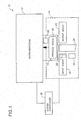
- an automated analyzer instrument 10 used to perform diagnostic tests on test samples includes instrumentation generally denoted 12 and a transport system 14.
- the instrumentation 12 may typically include an incubation chamber and processing stations similar to the types described in EP-A-712000, a luminometer which may be similar to the type described in EP-A-616208 and a fluid moving system generally provide from pipettes controlled by robotic arms.
- the transport system 14 allows a continuous supply of samples for uninterrupted testing.
- the transportation system 14 includes an input queue 16, a process queue 18 and an output queue 20.
- the input queue 16 moves sample-containing vessels such as test tubes, for example, toward a load position 22 located at one end of the input queue 16.
- the test tubes hold samples of patient bodily fluid specimens and the like to be analyzed by the analyzer instrument 10. Once the test tubes reach the load position 22, an infeed apparatus 24 moves the sample-containing test tube from the input queue 16 to a predetermined position on the process queue 18.
- the test tubes move from the input queue 16 to the process queue 18, the test tubes pass by a bar code reader 26 disposed proximate the load position 22 of the input queue 16.
- the bar code reader 26 deciphers a bar code typically attached to each test tube and to each rack by a label and transmits its information to a system controller 28 which performs a variety of functions including tracking the samples provided to the process queue 12 and scheduling the order in which the samples are tested.
- the instrumentation apparatus 32 aspirates a portion of the sample from the test tube and subsequently dispenses the sample portion into a reaction container such as a cuvette positioned in the instrumentation apparatus 11, where it is treated according to the above identified application EP-A-712000.
- the sample rack is generally held in the process queue until the test result is obtained. Thus, if a bad test result occurs the test can be rerun by aspirating a second portion of the sample from the test tube and dispensing the second portion into another reaction container.
- the process queue 18 positions the sample rack in front of an exit apparatus 30 which moves the sample rack from the process queue 18 to the exit queue 20. Once the test tube is moved to the exit queue 20, the sample-containing test tubes are again accessible to a user and are typically removed from the transport system 14 periodically.
- the process queue 18 is enclosed in protective housing 32 to prevent a user from accessing sample-containing test tubes after the test tubes have been moved from the input queue 16 to the process queue 18.
- the test tubes can be easily accessed and randomly ordered and arranged and re-arranged while on the input queue 16, the placement and ordering of the samples cannot be changed by a user once the samples are moved to the process queue 18 where controller has a record of their position.
- a transport system 14 includes an input queue 16, a process queue 18 and an exit queue 20.
- a plurality of sample racks generally denoted 33 are disposed on the input queue 16 which is provided having a generally rectangular shape.
- Each of the sample racks 33 is adapted to hold a plurality of sample-containing test tubes generally denoted 34 and thus the sample racks 33 allow multiple test tubes 34 to be simultaneously moved from the input queue 16 to the process queue 18 and from the process queue 18 to the output queue 20.
- one or more sample racks 33 may be placed by a user in any location on the input queue 16. While sample racks 33 are being moved along the input queue 16, the user can remove or arrange the sample racks 33 in a random or a predetermined order.
- the input queue 16 is typically an area of the automated analyzer instrument 10 (FIG. 1) which is highly accessible to a user.
- the input queue 16 is provided from a tray 38 having a rectangular shape and having a width W corresponding to an exemplary distance typically of about 5.2 inches and an exemplary length L corresponding to a distance typically of about 17.5 inches.
- the width W of the tray 38 should be selected to accommodate the length of the sample racks 33 and the length of the tray L should be selected to accommodate a number of sample racks 33.
- the sample racks 33 are loaded onto a first surface of the tray 38a such that a handle 39 of each of the sample racks 33 is positioned at a side of the tray 38 proximate the user.
- the handle 39 allows a user to easily hold and thus move and arrange sample racks 33 on the tray 38.
- Each of the sample racks 33 has a top surface 33a with a plurality of openings therein in which test tubes 34 may be disposed, a front-end, a back-end and a bottom surface having recesses 40 formed therein.
- the tray 38 includes a raised central portion 42 extending its length.
- the raised central portion 42 serves as a guide along which the sample-rack 33 travels as the sample rack 33 moves from a first end to a second end of the input tray 38 (left to right in the figure).
- the guide 42 may be provided as a piece separate from the tray 38, or preferably, the guide 42 may be provided as an integral part of the tray 38 as by plastic injection molding or stamping in aluminum.
- the guide 42 should be provided having a height selected to insure that the sample rack 33 does not catch on or become entangled on the guide 42.
- the tray 38 further includes a back edge guide 44 which engages a slot 46 in the back-end of the sample rack 33 to prevent the sample rack 33 from becoming dislodged from the tray 38 and to prevent the rack from tipping.
- the tray 38 is disposed on a housing 50 which encloses a drive system for the rack 33.
- the drive system moves the sample racks 33 along the top surface of the input tray 38 via a magnetic force generated on the underside of the tray 38.
- the tray 38 and housing 50 cover the drive system and thus isolate the drive system from the user environment.
- the tray 38 and the housing 50 completely enclose the drive system safety hazards due to exposure of a user to moving parts of the drive system are minimized. Furthermore, the tray 38 and cover 50 prevent fluid spills and other undesirable elements (e.g. dust and dirt) from contaminating the drive system or other areas of an analyzer system to which the transport system 14 is coupled and with which the sample transport system 14 cooperates. Also, since the user is not exposed to any moving parts, the drive system need not be shut down prior to or during cleaning of the tray 38 in order to prevent injury to a user or interference by a user with the operation of the drive system.
- undesirable elements e.g. dust and dirt
- the tray 38 is relatively easy to clean. Cleaning of the tray 38 is further unimpeded by sample rack positioning structures. This also allows the sample racks 33 to be arbitrarily loaded onto, removed from or rearranged on the tray 38 without interruption of the operation of the transport system 14.
- the process queue 18 is disposed adjacent the input queue 16 such that sample racks 33 may be conveniently and easily moved from the end of the input queue 16 to the process queue 18.
- the process queue 18 is mounted on a movable carrier member 52.
- a support block 54 Disposed on the carrier member 52 is a support block 54 which may be provided, as an aluminum member having a square cross-sectional shape and having a thickness typically of about one inch.
- the support block 54 supports a slide 58 a predetermined distance above the carrier member 52, and provides additional structural support to the carrier member 52.
- a drive 53 is coupled to move the process queue 18 in response to signals from controller 28.
- a process tray 60 mounts on the slide 58 to move on linear bearings mounted on a bottom surface of the process tray 60.
- the process tray 60 is provided having a plurality of equally spaced dividing walls 61 projecting from a base surface thereof.
- the dividing walls 61 form a plurality of slots 64 in which sample racks 33 may be held.
- An infeed apparatus 51 is mounted at a predetermined position on the input queue 16.
- the infeed apparatus 51 is mounted at an end of the tray 38.
- the infeed apparatus 51 which will be described in detail below in conjunction with FIGs. 3 and 4, moves the sample rack from the load position at the far end of the input queue 16 to an empty slot 64 of the process queue 18.
- the process tray 60 is directed by controller 28 to a position to insure that an empty slot 64 is available to receive the sample rack 33 provided by the infeed apparatus 51.
- the process tray 60 typically has mounted on one end or the other a probe tip tray 62 in a carrier 68.
- the probe tip tray 62 has a plurality of holes 66 in which a plurality of disposable probe tips 70 are arranged.
- the transport system 14 further includes an exit pusher 72 having a push rod 74 driven by a motor drive 76.
- the motor drive 76 drives the push rod 74 through a slot 64 whereby a sample rack 33 is moved from the process queue 18 onto a surface 78a of an exit tray 78 of the exit queue 20 under control of controller 28.
- the exit tray 78 includes a guide 80 similar to the guide 42 on the input tray 38. Guides 42, 44 80 and 99 are absent where the sample racks are moved to and from the process queue. Once a sample rack 33 is moved from the process queue 18 to the exit queue 20, an index mechanism, which will be described in detail in conjunction with FIG. 3A below, moves the sample rack along the top surface of the exit tray 78.
- the input queue 16 is selected having a tray long enough to hold twenty sample racks 33.
- each sample rack 33 holds five test tubes 34.
- Each of the test tubes 34 have a bar code label attached thereto.
- the test tubes 34 are oriented in the sample rack 33 such that the affixed bar code label is exposed to a bar code reader 83 disposed proximate a load position 22 of the input queue 16, where sample racks are moved out of the process queue.
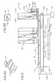
- the infeed mechanism 51 is here shown to include a belt 84 endlessly circulating around a pair of pulleys 86a, 86b. As may be more clearly seen in FIG. 4, a first one of the pulleys 86a is coupled to a bidirectional motor 104 such as a stepper motor.
- a plurality of outwardly extending paddles or profiles 88, 88a-88b coupled to the belt 84 are a plurality of outwardly extending paddles or profiles 88, 88a-88b.
- the profiles 88 are placed on a portion only of the belt 84.
- the locations of the end profiles 88a, 88h are selected such that a sample rack 33 can be positioned in the load position 22 between them while the profiles 88b-88h prevent a sample rack 33a adjacent the load position 22 from entering the load position as a rack is moved off between profiles 88a and 88h.
- the belt 84 and profiles 88 are urethane and may be manufactured as integral pieces using injection molding techniques.
- the profiles 88 may be manufactured as pieces separate from the belt 84.
- the profiles can be attached to the belt 84 via ultrasonic welding or any other fastening techniques well known to those of ordinary skill in the art.
- a load position guide 89 Coupled to the input queue 16 proximate the load position 22 is a load position guide 89.
- the load position guide 89 prevents tipping of the sample rack in the load position 22.
- the load position is available to accept a sample rack 33.
- the sample rack 33 which was adjacent the profiles 88 is then moved into the space of load position 22 where its presence is sensed by a sensor as described below.
- the motor 104 (FIG. 4) then drives the belt 84 and profiles 88 in a clockwise direction. Coupled to profile 88a is an aluminum block 90 which contacts a first end of the sample rack 33 which is now placed in the load position 22 of the input queue 16. As the belt 84 moves in a clockwise direction, the sample rack 33a is pushed from the load position 22 of the input tray 38 to an open slot 64 in the process queue 18 by controller 28.
- Block 90 extends the distance which the surface contacting the end of the sample rack 33 travels ensuring that the sample rack 33 is pushed completely off the input queue 16 and completely on to the process queue 18.
- the process queue 18 accepts the sample racks 33 fed thereto by the infeed mechanism 51. As described above, the process queue 18 moves linearly along a track such that sample racks 33 from the input queue 16 may be fed into different spaces 64 of the process queue 18. Also the process queue 18 moves along the track to align particular sample racks 33 with the exit pusher 72 under control of controller 28.
- the process queue 18 positions sample racks 33 whose samples have been successfully tested in the process queue 18 in front of the exit pusher 72.
- the exit pusher 72 includes the push rod 74 driven by a bidirectional motor 76.
- a pusher 108 (FIG. 3A) in a pusher assembly 100 pushes the sample rack out onto the exit queue.
- a sensor 98 at an end of the exit queue 20 indicates to the controller 28 when the exit queue 20 fills with sample racks 33 a signal and either notify a user to take some action such as removing sample racks 33 from the exit queue 20 and/or prevent any additional sample racks 33 from being moved from the process queue 18 to the exit queue 20 until space is made available on the exit queue 20.
- the sensor may be disposed on a top or bottom surface of the tray 78.
- the transport system 14 also has an emergency sample rack entry queue 105.
- Entry queue 105 includes a stat-entry position 101, a stat sensor 102 and a stat-load position 103.
- the purpose of the stat-entry queue 105 is to allow a user to have the analyzer system 10 perform a test out of order as soon as possible on any samples loaded the in stat-entry queue 105.
- stat sensor 102 When a user places a sample rack 33 into the stat-entry position 101, the stat sensor 102 activates pusher block 108 (FIG. 3A) which pushes the sample rack from the stat-entry position 101 to the stat-load position 103 with profiles 88 set to the appropriate side of belt 84.
- a stat-load position guide 113 is disposed proximate the stat-load position 103 to prevent tipping of the sample rack in the stat-load position 103.
- the infeed apparatus 51 then moves the sample rack from the stat-load position 103 to process queue 18 by reverse rotation of the belt 84.
- the transport system 14 further includes the bar code reader 83 disposed proximate the stat-entry position 101. Portions of the bar code reader 83 have here been removed to allow a clearer view of the pusher bar 106 and pusher block 108.
- the bar code reader 83 is held in a fixed position above the pusher block 108 by a mounting member 109 which may be provided as a mounting bracket for example.
- the bar code reader 83 is preferably positioned such that it can read bar codes on labels attached to the test tubes being moved to the process queue 18 from either the load position 22 (FIG. 3) on input queue 16 or from the stat-load position 103.
- the bar code labels move past the bar code reader 83 and the bar code reader 83 decodes the information from the bar code label and sends such information to the system controller 28 (FIG. 1).
- This information may include, patient, sample, and other direct fluid data. Tests to be run on each sample are entered separately into controller 28. Some samples may be identified for "batch runs" meaning a specified set of tests for all specimens in the batch.
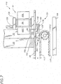
- a magnetic conveyor 110 is provided for the input queue 18.
- the drive system 116 includes first and second drive belts 117 disposed around a pair of pulleys 118a, 118b, driven by a drive motor 119. Belts 117 are placed near front and back portions of tray 38
- the drive motor 119 is here provided as a stepper motor 119 having a drive gear 123 coupled to pulley 118b which is provided as a pulley gear 118b (FIG. 5B).
- the coupling is accomplished with a 2:1 gear reduction ratio.
- the drive motor 119 may be disposed below the transport tray 38 and coupled to pulley 118a via a drive belt 120.
- a plurality of magnet assemblies 121a-121e are coupled to each drive belt 117.
- the magnet assemblies 121a-121e are equally spaced apart by a predetermined distance.
- the tray 38 is spaced a predetermined distance above the belt 117 such that the magnet assemblies 121a, 121c and 121e as shown in FIG. 5, pass under the tray 38 a predetermined distance.
- Each magnet assembly 121a-121e includes a magnet having a magnetic force of sufficient strength such that a magnetic force is present at least at, and in this embodiment preferably above, the surface 114a of the tray 78.
- the sample racks 33 include a magnetically attractive region engageable by the magnetic force of magnet assemblies 121.
- the magnet assemblies 121 thus magnetically couple the sample racks 33 to the drive system such that drive system moves the sample racks 112 along the surface of the tray 38.
- each magnet assembly 121a-121e is driven around the pair of pulleys 118 via the belt 117 and move the sample racks 112 along the transport tray 114.
- the distance by which the magnet assemblies 121 are spaced from each other is selected in accordance with a variety of factors including but not limited to the number of sample racks 33 each individual magnet assembly 121 can move.
- each magnet assembly 121 is of a magnetic strength sufficient to move several sample racks 33.
- the conveyor system 110 further includes a sensor 124 coupled to a base plate 126 and disposed below a surface of the belt 117.
- the sensor 124 may be provided as a Hall effect sensor, for example, and is disposed to provide a signal whenever a magnet assembly 121 passes thereover. The sensor 124 thus indicates the position of a magnet assembly 121. Since the location of each of the magnet assemblies 121a-121e on the belt 117 with respect to the other is known, when the location of one of the magnet assemblies 121 is known, the location of each of the magnet assemblies 121 is known.
- the transport system 110 further includes a load position sensor 128 which may, for example, be provided as an optical sensor which detects light reflected from a surface of a sample rack 33 adjacent it.
- a load position sensor 128 which may, for example, be provided as an optical sensor which detects light reflected from a surface of a sample rack 33 adjacent it. In operation, as a sample rack 33 moves into the load position in front of profile 88a, light reflects off a surface 201 (Fig. 10) of the sample rack 33 and activates the load position sensor 128.
- the drive motor 119 coupled to pulley 129 turns the belt 117 in a clockwise direction until, typically three magnet assemblies 121 pass by the sensor 124. This step ensures that any sample rack 33 positioned on the left most side of the tray 38 travels the entire length of the tray 114.
- the drive motor 119 then turns the belt 117 in a counterclockwise direction by a predetermined short distance typically 0.06 in.) to relieve any pressure applied to a sample rack in the load position due to an adjacent sample rack .
- a predetermined short distance typically 0.06 in. typically 0.06 in.
- the drive system here provided from the belt 117, pulleys 118 and motor 119 is completely independent of the tray 38 and magnet assemblies 121.
- the drive system 116 may be alternatively implemented by any means for moving the magnet assemblies 121 such as electromagnetic means or other means.
- the magnet assemblies may be provided as having electromagnets which may be turned on and off to attract the magnetically attractive regions of the sample racks.
- electromagnets may be moved via a conveyor type belt similar to belt 117 or via pusher rods which move back and forth in a linear direction below the tray. With the pusher rod approach the electromagnets would be activated as the push rods move the magnets and thus sample racks from a position distal to the load position to a position proximate the load position. The electromagnets would then be de-activated prior to the push rods retracting the electromagnets from the load position. Furthermore, with the input tray completely filled, in the case where electromagnets are used on belt 117, it need not be turned off to prevent magnet forces from continuously pushing against the sample racks, rather, the electromagnets may be turned off.
- FIG. 6 a portion of the magnetic conveyor 110 described above in conjunction with FIG. 5, is shown having three sample racks 33 disposed thereon. Top portions of each of the sample racks 33 have been removed to reveal test tubes 130 disposed in each of the sample racks. A bottom portion of the sample rack 33, has been cut away to expose in section, a plate 134 disposed in a bottom portion of the sample rack 33.
- the plate 134 may be provided from any magnetically attractive material.
- the plate 134 is provided from magnetic stainless steel having a thickness typically of about .125 inches. In alternate embodiments, however, other materials such as iron, non-stainless steel or even a magnet material may also be used. In the event that plate 134 is provided from a magnet material care should be taken to ensure that a magnetic pole of plate 134 is not in opposition to a magnetic pole of magnet assembly 121.
- the magnet assemblies 121 include an aluminum housing 136 having a thickness typically of about .090 inches over which shown in section, a backing plate 138, a bar magnet 140 and a magnet cover 142, are disposed.
- the backing plate 138 is provided from magnetic stainless steel and is provided having a thickness typically of about .060 inches.
- the magnet 140 may be provided as a neodymium-iron-boron magnet having a thickness typically of about .250 inches and the magnet cover 142 may be provided from a plastic material such as Acetal or any similar material having a thickness typically of about .040 inches.
- the magnet assembly 121 is coupled to a profile 144 projecting from a surface of the belt 117.
- the profile 144 may be similar to the profiles 88 described above'in conjunction with FIGs. 3 and 4.
- the magnet assemblies 121 can be coupled to the profile 144 via screws which pass through clearance holes provided in the profile 144 and mate with threaded holes provided in the aluminum housing 136 or may be fastened to the profile 144 via epoxy or welding techniques well known to those of ordinary skill in the art.
- the backing plate 138 is provided to increase the strength of the magnetic field provided by the magnet 140 by providing a return path coupling assemblies 121 for each belt 117.
- the backing plate 138 also modifies the configuration of the magnetic field provided by magnet 140.
- the magnet 140 is spaced a distance below the tray surface such that the magnetic field is concentrated in a region at or above the surface of tray 38 upon which the sample racks 33 are disposed.
- a first edge of the plate 134 forms a right angle with the tray surface thus generating a relatively strong magnetic couple such that the magnet assemblies 121 can pull the sample racks 33.
- a second, rearward edge of the plate 134 is provided having an angled surface as will be described further below.
- the tray 38 is, in this embodiment, provided from an aluminum sheet having a thickness typically of about .0625 inches.
- the surface of the aluminum sheet on which the sample racks 33 are disposed is provided having a polytetrafluorethylene type of coating, such as Teflon® disposed thereon to reduce frictional forces between the tray 38 surface and the contacting surface of the sample racks 33.
- Teflon® a polytetrafluorethylene type of coating
- FIG. 7 a portion of the conveyor system 110 is shown having sample rack 33 disposed in the load position of an input queue.
- the load position corresponds to a channel defined on one side by a shoulder 38c of the tray 38.
- a load position guide 150 is disposed proximate the load position. In operation, as the sample rack 33 is moved into the load position of the input queue, the load position guide 150 engages a slot 152 formed in the front end of the sample rack 33. The guide 150 ensures that the sample rack 112 is properly aligned in the load position.
- the sensor 128 sends a signal which under control of controller 38 activates the infeed apparatus 51 and causes the belt 84 to turn the profile 88a and member 90 (FIG. 3) to drive the sample rack 33 onto the process queue.
- the profile 88a is provided having a height H typically of about one inch, a width W typically of about .750 inches and a thickness T typically of about .125 inches.
- a bottom edge 89 of profile 88a is spaced a predetermined distance from the top surface of the tray 38, typically of about .25 inches.
- the magnet assembly 121 is coupled to the profile 144 projecting from the belt 117. As the magnet assembly 121 approaches the end of the tray 38 proximate the profiles 88 and pulley 118a, the magnet assembly 121 is extended past the end of the pulley 118a, insuring that the sample rack 33 is moved completely into the load position of the tray 38. Thus, by coupling the magnet 140 to the profile 144 as described above, the magnet assembly 121 moves the sample rack 33 past the end of the belt 117 as it rounds the pulley 118a.
- the pulleys 118a or 118b have sets of teeth to engage corresponding recesses in the belt 117 to preserve indexing.
- the pulleys 118 turn to move the belt 117 an additional distance to move any other sample racks 33 on the tray 114 toward the load position.
- the belt 117 stops moving, with one of magnet assemblies 121 positioned by controller 28 under the sample rack which is next in line to be moved to the load position when the belt 112 executes a short move back away from the load position, the sample rack 37 in the load position remains in the load position while the other sample racks 33 moves away slightly to prevent jamming at the load position.
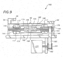
- the drive assembly 116 is shown to include a pair of like stainless steel shafts 162, 164 spaced apart and disposed at opposing ends of tray 114.
- shaft 164 each end of the shaft 164 is coupled to a ball bearing assembly 166 mounted as shown in respective ends of mounting plates 167a, 167b generally denoted 167 extending below tray 114.
- the ball bearing assemblies 166 allow the shafts 162, 164 to rotate relative to the mounting plates 167.
- Each shaft 162, 164 has mounted thereon the paired drive pulleys 118a, 118b. Disposed adjacent one belt pulley 118b is a drive gear 123.
- an alternate drive pulley 176 is coupled to a shaft 164, and driven by a drive motor 177 the through shaft 122, pulley 181 and belt 180.
- the drive shaft 162 is here provided from a pair of shafts 192, 194 held together by a combination of shoulder regions 196 and a locking collar 198.
- the shafts 162, 164 can be easily assembled and disassembled to allow easy access for repair and replacement.
- an input queue back edge guide 44, a load guide 89, and an output queue back edge guide 99 are disposed on the tray 114.
- a sample rack 200 corresponding to rack 33 has first and second opposing ends 200a, 200b, a top surface 200c, a bottom surface 200d (FIG. 14) and a pair of opposing side surfaces 200e, 200f (FIG. 16).
- An optional reflective member 201 is disposed on surface 200e.
- the reflective member, 201 reflects light to activate optical sensor 128 (FIG. 5).
- the reflective member can be disposed along any portion of surface 200e where it may be aligned to activate sensor 128.
- member 201 is omitted (FIG. 11) and surface 200e is made of a reflective material or polished such that light incident thereon is reflected and activates sensor 128.
- a plurality of openings 202a-202e are formed in top surface 200c of rack 200 in the typical case there are five openings.
- the openings 202a-202e are provided having a shape selected to accept a sample containing vessel.
- the openings 202 are provided having a circular shape selected to accommodate test tubes in a range of sizes.
- Each of the openings 202a-202e has a corresponding slot 204a-204e formed in the side surface 200e of the sample rack 200.
- the slots 204a-204e extend from the top of the respective openings 200a-200e toward the bottom surface 200d of the sample rack 200.
- a finger spring 206a-206e Disposed in each of the openings 202a-202e is a finger spring 206a-206e.
- openings 202 are provided having a length typically of about 1.7 inches and a diameter typically of about .675 inches.
- Springs 206 are provided having a length typically of about 1.5 inches and a width typically of about .313 inches and slots are provided having a width typically of about .345 inches.
- the slot walls 205 (FIG.
- FIGs. 18A-C are section views down the middle of a slot 204 of a sample rack 33 showing installation and compression in use, holding a test sample container 34, of a spring 206.
- a spring 206 At the rear of each slot 204 are top and bottom lipped spring retaining grooves 203 and 205 respectively.
- the grooves are formed by ridges 207 that are formed on each side of the slot 204 creating two grooves 203 and 205.
- the springs 206 have rolled ends 208 which aid in retaining the spring in the rack by slipping over the tips of grooves 203 and 205.
- the normal unstressed position of the spring 206 is shown in FIG. 18A.
- the bottom end 208 fails to reach grooves 205 until this spring is extended during installation so that lower rolled end 208 falls into grooves 205.
- spring 206 is stressed further under a force 211 extending the bottom end 208 downward into a slack accommodation extension 213 of groove 205.
- tube removal spring 206 returns to the state of FIG. 18B.
- the test tube 214 has affixed thereto a bar code label 216. A portion of the test tube 214 to which the bar code label is attached is exposed through the slot 204a and thus visible to the reader 83.
- sample racks can hold test tubes having a range of diameters, it should also be noted that within this range it is preferable to place test tubes having similar diameters in the same sample rack. Thus, and as will be described further below, while each sample rack can hold test tubes having a diameter in the range of 10.25-16.5 mm it may be desirable to designate particular racks to hold test tubes having diameters within a particular range.
- the openings 202a-202e are provided having a circular cross sectional shape, other cross sectional shapes may also be used.
- the opening may be provided having a rectangular, square, triangular or any other cross-sectional shape.
- the opening may be provided having tapered walls to thus more easily hold cone-shaped vessels.
- the particular shape of the opening should be selected such that the sample-containing vessel disposed therein can be easily placed into and removed from the sample rack 200.
- the openings 202a-202e need not all have the same shape. Regardless of the size and shape of the openings, the spring arrangement described above can be employed to secure and firmly hold the sample-containing vessels therein.
- the front end of the sample rack has load slot 152 formed therein.
- the load slot 152 accepts the load guide 150, (FIGs. 7 and 9 respectively) to thus properly align the sample rack 200 in the load position of the input queue.
- the back end of the sample rack 200 has opening 46 which mates with the input queue edge guide 48 (FIGs. 2, 3) and exit queue edge guide 99 (FIGs. 2, 3).
- the opening 46 includes a raised portion 222 which engages a corresponding shape on the input queue guide 48 which assists in locating the sample rack 200 on the input queue and prevents the rack 200 from tipping over or sliding off of the input queue.
- the back edge guide 99 is provided as an L-shaped member.
- the guide 99 thus mates only with a front portion 46a of the opening 46 such that the racks may be easily removed from the exit queue.
- the sample rack 200 also includes a handle 224 with which a user may carry the sample rack 200.
- a top angled portion of the handle has a depression 226 formed therein to lend an ergonomic design which is comfortable for a user to grasp.
- the handle 224 also has a side surface 228 on which may be attached a vertical bar code label 229.
- the vertical bar code label 229 has a plurality of barcodes disposed thereon.
- the barcodes identify the size (e.g. diameter range) of test tubes which are accommodated in the sample rack 200.
- a sliding clip 233 is disposed around the handle 224 of the sample rack 200 and a user arranges the clip 233 to indicate the size of test tube actually disposed in the sample rack 200.
- a further barcode region 230 identifies the sample rack serial number. Thus each individual sample rack has its own unique identifying number.
- the barcode reader In operation, when the sample rack 200 is moved from the input queue to the process queue the barcode reader reads the barcode on label 228 which are either not blocked by or are emphasized by the sliding clip 233. Thus the barcode reader can identify the type (i.e. the size) of the test tube disposed in the sample rack 200. As mentioned above the sample rack 200 is able to hold test tubes having different diameters and shapes. However, to improve alignment at the sample probe with the opening of the test tube, the system controller preferably knows the type of the test tube.
- the entire sample rack 200 including handle 224 may be provided as a single piece via injection molding techniques.
- the test tube carrying portion of the sample rack 200 and the handle 224 may be provided as separate pieces and mated together via screws, epoxy, or any other fastening technique well known to those of ordinary skill in the art.
- a pair of screws in holes 231a, 231b secure the handle 224 to the base portion of the sample rack 200 via screws 231c, not shown.
- each of the holes 202 may optionally be provided with slots 225 formed in the bottom thereof to stabilize the test tube in the holes 202.
- the bottom surface of the sample rack 200 has a grove 234 formed therein which mates with and accommodates the guides 42, 80 (FIG. 2) of the input and exit queues.
- the bottom surface of the sample rack 200 also has formed therein a pair of rectangular shaped cavities 240 (FIG. 13).
- a magnetically attractive member 244 (FIG. 15) is disposed in each of the cavities 240.
- the magnetically attractive member may be molded into the bottom surface of the sample rack.
- a cover 246 may likewise be fastened to the sample rack over member 244.
- the members 244 are symmetrically disposed about a latitudinal center line 245 of the sample rack 200.
- each of the magnetically attractive members 244 is provided as a magnetically attractive stainless steel plate having a generally rectangular shape. As may be more clearly seen in FIG. 15, a first portion 244c of the bottom surface is slightly recessed from (or substantially aligned with) the bottom surface of the sample rack 200. A second portion 244b of the plate 244 angles into the rack 200 body as discussed above.
- a magnet assembly 121 approaches the sample rack from a direction such that the magnet first attracts the angled second portion 244b of the member 244.
- the force of the magnetic field provided from the magnet assembly 120 (FIG. 6) is gradually introduced to the member 244.
- a pair of covers 246 are disposed over the openings 240.
- the covers 246 fit into grooves 247 (FIG. 15) formed proximate the openings 240.
- the covers 246 are selected to have a size and shape such that the cover 246 forms a snap fit in the openings 240 to thus secure the plates 244 in the rack 200 while leaving exposed at least a portion of the member 244 (FIG. 14).
- sample rack members 244 are spaced apart and positioned in the bottom surface of the sample rack 200 such that when the sample rack 200 is placed on a tray of a conveyor system such as the conveyor system of FIG. 8, the magnet assemblies 173, (FIG. 8) coupled to the belts 170a, 170b (FIG. 8) pass directly under the members 244.
- a pair of raised portions or rails 250, 252 Projecting from a bottom surface of the sample rack 200 are a pair of raised portions or rails 250, 252.
- the rails 250, 252 space the bottom surface of the sample rack along with member 244 from the queue surface and thus the member 244 from a surface on which the racks are placed.
- the rails 250, 252 decrease the surface area of the sample rack 200 which contacts, for example, the surface of the tray 114 (FIGs. 5, 6) on which the rack 200 is placed. Consequently frictional forces between the sample rack 200 and the tray 38 are reduced. This results in a lower magnetic force being required to move sample racks 200 along the tray 38.
- the drive system could be provided having a single belt and magnet coupled thereto.
- the belt and magnet would preferably be disposed along a central longitudinal axis of a transport tray.
- the sample rack would include a single magnetically attractive region disposed in the center of the sample rack and aligned with the single belt and magnet when the sample rack is placed on the transport tray.
- the plate could be provided having different thicknesses on each end.
- a first end of the plate could be relatively thin and a second end of the plate could be relatively thick.
- a magnet coupled to a drive system would first encounter the thin end of the plate. This would result in a relatively weak magnetic coupling. The magnet would then engage the thick end of the plate with a relatively strong force. With this arrangement, the sample rack would smoothly transition from a stationary state to a moving state.
Abstract
Description
- This invention relates to a sample transport system; more particularly, it relates to moving test samples into and out of an analyzer instrument by a magnetic conveyor system.
- As is known in the art, there is a trend in hospitals, clinics, laboratories and other locations to perform tests (assays) on samples of patient specimens such as blood, spinal fluid, urine, serum, plasma, and the like using automated analyzer systems. The samples are typically placed in a container such as a sample cup, a primary tube, a cuvette or any other suitable container. One or more of such containers may then be arranged in a so-called sample rack.
- The sample rack is placed in a load area or input queue of the analyzer instrument and then is moved to a position where at least a portion of the sample is collected for testing in the analyzer instrument. After the sample is collected for testing in the analyzer instrument, the sample rack is moved to an output or exit queue where the user can remove the sample rack from the analyzer instrument. Thus, a user can physically place sample racks holding one or more samples to be tested in the load area and after the samples are collected the user can remove the sample racks from the output queue. Thus, the entry and exit queues of the analyzer instrument are generally exposed to a user.
- In a typical analyzer instrument, mechanical pushers or conveyor mechanisms are used to move the sample racks along the input and output queues. In the mechanical pusher approach, a pusher apparatus is positioned above a tray on which the sample racks are disposed. A lead screw driven by a motor or a spring driven push block pushes the sample racks along a surface of the tray.
- When such mechanical pushers are used in input and output sample queues where user interaction is high, special precautions generally must be taken to insure safe operation. For example, safety shields and safety guides are generally used to cover the mechanical pusher to thus prevent a user from being harmed by moving parts to which the user would otherwise be exposed. Such precautions lead to the mechanical pusher having additional parts which in turn leads to a relatively complex design.
- Moreover, the input and output queues are generally susceptible to sample fluid spills and thus it is important to allow the queues to be easily cleaned. The above mentioned safety precautions, however, limit user accessibility to the tray. Furthermore, due to the likelihood of the user being harmed by a moving machinery, it is undesirable for a user to attempt to clean the tray while the pusher apparatus is operating. Thus, the pusher apparatus is preferably stopped to allow the user to clean the input and exit queues in the regions proximate the pusher mechanisms. This usually slows or stops operation of the system.
- Furthermore, any openings in the surface of the input and output trays upon which the sample racks are placed may expose interior portions of the transport system or analyzer instrument to fluid spills. Such interior areas are generally not easily accessible and if such areas become contaminated by fluid, further complications arise in the cleaning procedures.
- Conveyer type mechanisms have similar problems. In the conveyor approach, a sample rack is placed on a belt which continuously moves around two or more wheels or pulleys. If a fluid sample spills onto the moving belt, the belt carries the fluid to interior areas of the conveyor system thereby possibly contaminating inner portions of the conveyor system or analyzer instrument.
- An additional concern in the conveyor approach is that the sample racks are moved to one end of either the input or exit queues and come to rest against a rack stop. The conveyor belt, however, must continuously slide under the racks which have collected and rest in a fixed position at the end of the queue. This may lead to considerable wear on the belt as well as on the bottom surface of the sample racks which are stationary at the end of the queue.
- It would thus be desirable to provide a sample transport system which moves sample racks along a transport tray while minimizing the risk of injury to a user, maximizes user accessibility to test samples on input and exit queues and minimizes the amount of effort required to clean input and exit queues.
- In accordance with the present invention, a transport system for moving a sample rack having a magnetically attractive region includes a drive system, a magnet coupled to the drive system and movable in response to the drive system and a tray having a first surface adapted to receive the sample rack wherein the first surface of the tray is disposed over and spaced a predetermined distance from a first surface of the magnet such that a magnetic force provided by the magnet is present at the first surface of the tray. With this particular arrangement, a magnetic conveyor system is provided. By disposing the tray over the drive system, the drive mechanism is completely isolated from the user thus minimizing safety hazards. Furthermore, since the sample racks are magnetically coupled to the drive system, the surface of the tray need not move or contain any slots or particular indexing regions. Thus in the event of a fluid spill, the fluid is prevented from contaminating internal regions of the transport system and analyzer system. Furthermore, the tray may be provided from a material which promotes cleaning thereby enabling the tray to be easily cleaned. For example, the tray may be fabricated of aluminum having a Teflon surface coating. Also, the tray can be coupled to a cover which completely encloses the drive system and further protects the drive system from sample spills and other contaminants. Moreover, the tray surface upon which racks are disposed is stationary and thus does not cause excessive wear of the sample racks due to constant rubbing of a moving belt on the bottom surface of a stationary sample rack. Furthermore, there are no moving parts to which a user is exposed and thus the transport system minimizes the safety concerns of a user in highly accessible areas such as an input queue of an analyzer instrument.
- The tray is provided having a rectangular shape with a length selected to hold a predetermined number of sample racks. In one embodiment, each sample rack holds one or more test tubes. The sample racks may be loaded onto any portion of the tray which serves as an input queue of the analyzer instrument. The drive system located beneath the first surface of the tray includes a first shaft disposed below a first end of the tray and a second shaft disposed below a second different end of the tray. The shafts are rotatably mounted in a base. Each shaft has a pair of pulleys disposed on opposite ends thereto. A urethane belt is disposed around opposing pulleys of the two shafts. A plurality of bar magnet assemblies extend between the urethane belts. The pulley sets synchronously drive the two urethane belts and thus the magnet assemblies. The magnet assemblies include a pair of magnets oriented such that opposite poles of each magnet face the same tray surface forming a magnet circuit which includes a magnetic field above the first surface of the tray. The magnet assemblies and the first surface of the tray are closely spaced such that the magnets freely move with the urethane belts below the surface of the tray.
- In one embodiment, each sample rack is provided having two cavities on a bottom surface thereof. The cavities are symmetrically located about opposite sides of a center line of the sample rack. Disposed in each of the cavities is a magnetizable plate positioned at the bottom surface of the sample rack such that when the sample rack is disposed on the tray the plates are aligned with the magnets of the magnet assemblies which pass below the surface of the tray. The magnetic field generated by the magnet assemblies attract the plates disposed in the bottom surface of the sample rack and engages the plate with sufficient force such that the sample rack moves in concert with the magnet assembly as the belts move. At least a portion of a first surface of the plate may be disposed at an angle with respect to the surface of the magnet assembly such that the magnetic force provided by the magnet assemblies gradually builds as the belts move to lower the backward acceleration of the rack as the magnet assembly first approaches the sample rack. Consequently, the sample rack smoothly transitions from a stationary state to a moving state.
- The sample rack is also provided having a pair of rails projecting from the bottom surface thereof. The rails decrease the surface area of the sample rack which contact the tray and thus reduce frictional forces between the sample rack and the tray. The bottom surface of the sample rack is also provided with a recess region which accepts projecting guide from the first surface of the tray. The guide positions the sample rack along the tray. The sample rack also includes front and back edge guides which prevent the sample rack from tipping while it is on the tray and ensures that the rack is properly aligned on the tray. The front edge guide prevents the sample rack from tipping when the sample rack is placed in a load position of the tray.
- The sample rack has openings to accept sample-containing vessels such as test tubes. Disposed on each of the openings is a finger spring which. is placed in compression when a sample-containing vessel is placed in the opening, thus securing the sample vessel in the sample rack. The spring is sized such that different size test tubes may be placed and properly secured in the sample rack.
- The foregoing features of this invention as well as the invention itself may be more fully understood from the following detailed description of the drawings in which
- FIG. 1 is a block diagram of an automated analyzer instrument;
- FIG. 2 is a perspective view of a sample transport system having an input queue and a process queue and an output queue;
- FIGs. 3 and 3A are a top view of a sample transport system;
- FIG. 4 is a perspective view of a sample transport system;
- FIG. 5 is a portion of a side view of a sample transport system;
- FIGs. 5A and 5B show alternative details of FIG. 5;
- FIG. 6 is a cross sectional view of a sample rack and a magnet assembly;
- FIG. 7 is a side view of a portion of a sample transport system;
- FIG. 8 is a bottom view of a drive system;
- FIG. 9 is an end view of an alternative drive system;
- FIGs. 10 and 11 are a series of perspective views of a sample rack;
- FIG. 12 is a top view of a sample rack;
- FIG. 13 is a is a side view of a sample rack;
- FIG. 14 is a bottom view of a sample rack;
- FIG. 15 is a side view of a sample rack;
- FIG. 16 is a cross sectional view of a portion of a magnetic sample rack;
- FIG. 17 is an end view of a sample rack; and
- FIGs. 18A-18C are a cross sectional view of a sample rack slot showing installation and compression of a spring.
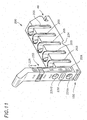
- FIG. 19 is a front perspective view of a design for a sample rack according to the invention;
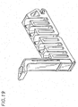
- FIG. 20 is a rear perspective view of a design for a sample rack according to the invention;
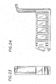
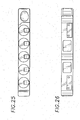
- FIG. 21 is front side elevational view of a design for a sample rack according to the invention;
- FIG. 22 is a front elevational view of a design for a sample rack according to the invention;
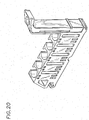
- FIG. 23 is a rear side elevational view of a design for a sample rack according to the invention;
- FIG. 24 is aback side elevational view of a design for a sample rack according to the invention;
- FIG. 25 is a top view of a design for a sample rack according to the invention;
- FIG. 26 is a bottom view of a design for a sample rack according to the invention;
- FIG. 27 is s front perspective view of an alternative design for a sample rack according to the invention;
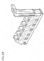
- FIG. 28 is a rear perspective view of an alternative design for a sample rack according to the invention;
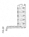
- FIG. 29 is front side elevational view of an alternative design for a sample rack according to the invention;
- FIG. 30 is a back side elevational view of an alternative design for a sample rack according to the invention;
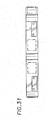
- FIG. 31 is a bottom view of an alternative design for a sample rack according to the invention;
-
- Referring now to FIG. 1, an
automated analyzer instrument 10 used to perform diagnostic tests on test samples includes instrumentation generally denoted 12 and atransport system 14. Theinstrumentation 12 may typically include an incubation chamber and processing stations similar to the types described in EP-A-712000, a luminometer which may be similar to the type described in EP-A-616208 and a fluid moving system generally provide from pipettes controlled by robotic arms. Thetransport system 14 allows a continuous supply of samples for uninterrupted testing. - The
transportation system 14 includes aninput queue 16, aprocess queue 18 and anoutput queue 20. Theinput queue 16 moves sample-containing vessels such as test tubes, for example, toward aload position 22 located at one end of theinput queue 16. The test tubes hold samples of patient bodily fluid specimens and the like to be analyzed by theanalyzer instrument 10. Once the test tubes reach theload position 22, aninfeed apparatus 24 moves the sample-containing test tube from theinput queue 16 to a predetermined position on theprocess queue 18. - As the test tubes move from the
input queue 16 to theprocess queue 18, the test tubes pass by abar code reader 26 disposed proximate theload position 22 of theinput queue 16. Thebar code reader 26 deciphers a bar code typically attached to each test tube and to each rack by a label and transmits its information to asystem controller 28 which performs a variety of functions including tracking the samples provided to theprocess queue 12 and scheduling the order in which the samples are tested. - Once a test tube is moved in a sample rack to the
process queue 18 theinstrumentation apparatus 32 aspirates a portion of the sample from the test tube and subsequently dispenses the sample portion into a reaction container such as a cuvette positioned in the instrumentation apparatus 11, where it is treated according to the above identified application EP-A-712000. - After the sample is aspirated from the test tube and dispensed into the reaction container, the sample rack is generally held in the process queue until the test result is obtained. Thus, if a bad test result occurs the test can be rerun by aspirating a second portion of the sample from the test tube and dispensing the second portion into another reaction container. Once each sample in a sample rack has been successfully tested, the
process queue 18 positions the sample rack in front of anexit apparatus 30 which moves the sample rack from theprocess queue 18 to theexit queue 20. Once the test tube is moved to theexit queue 20, the sample-containing test tubes are again accessible to a user and are typically removed from thetransport system 14 periodically. - The
process queue 18 is enclosed inprotective housing 32 to prevent a user from accessing sample-containing test tubes after the test tubes have been moved from theinput queue 16 to theprocess queue 18. Thus while the test tubes can be easily accessed and randomly ordered and arranged and re-arranged while on theinput queue 16, the placement and ordering of the samples cannot be changed by a user once the samples are moved to theprocess queue 18 where controller has a record of their position. - Referring now to FIG. 2, 3, 3A and 4 a
transport system 14 includes aninput queue 16, aprocess queue 18 and anexit queue 20. A plurality of sample racks generally denoted 33 are disposed on theinput queue 16 which is provided having a generally rectangular shape. Each of the sample racks 33 is adapted to hold a plurality of sample-containing test tubes generally denoted 34 and thus the sample racks 33 allowmultiple test tubes 34 to be simultaneously moved from theinput queue 16 to theprocess queue 18 and from theprocess queue 18 to theoutput queue 20. - In operation, one or more sample racks 33 may be placed by a user in any location on the
input queue 16. While sample racks 33 are being moved along theinput queue 16, the user can remove or arrange the sample racks 33 in a random or a predetermined order. Thus, theinput queue 16 is typically an area of the automated analyzer instrument 10 (FIG. 1) which is highly accessible to a user. - The
input queue 16 is provided from atray 38 having a rectangular shape and having a width W corresponding to an exemplary distance typically of about 5.2 inches and an exemplary length L corresponding to a distance typically of about 17.5 inches. The width W of thetray 38 should be selected to accommodate the length of the sample racks 33 and the length of the tray L should be selected to accommodate a number of sample racks 33. - The sample racks 33 are loaded onto a first surface of the
tray 38a such that ahandle 39 of each of the sample racks 33 is positioned at a side of thetray 38 proximate the user. Thehandle 39 allows a user to easily hold and thus move and arrangesample racks 33 on thetray 38. - Each of the sample racks 33 has a
top surface 33a with a plurality of openings therein in whichtest tubes 34 may be disposed, a front-end, a back-end and a bottomsurface having recesses 40 formed therein. - The
tray 38 includes a raisedcentral portion 42 extending its length. The raisedcentral portion 42 serves as a guide along which the sample-rack 33 travels as thesample rack 33 moves from a first end to a second end of the input tray 38 (left to right in the figure). - The
guide 42 may be provided as a piece separate from thetray 38, or preferably, theguide 42 may be provided as an integral part of thetray 38 as by plastic injection molding or stamping in aluminum. Theguide 42 should be provided having a height selected to insure that thesample rack 33 does not catch on or become entangled on theguide 42. - The
tray 38 further includes aback edge guide 44 which engages aslot 46 in the back-end of thesample rack 33 to prevent thesample rack 33 from becoming dislodged from thetray 38 and to prevent the rack from tipping. - The
tray 38 is disposed on ahousing 50 which encloses a drive system for therack 33. The drive system moves the sample racks 33 along the top surface of theinput tray 38 via a magnetic force generated on the underside of thetray 38. Thetray 38 andhousing 50 cover the drive system and thus isolate the drive system from the user environment. - Since the
tray 38 and thehousing 50 completely enclose the drive system safety hazards due to exposure of a user to moving parts of the drive system are minimized. Furthermore, thetray 38 and cover 50 prevent fluid spills and other undesirable elements (e.g. dust and dirt) from contaminating the drive system or other areas of an analyzer system to which thetransport system 14 is coupled and with which thesample transport system 14 cooperates. Also, since the user is not exposed to any moving parts, the drive system need not be shut down prior to or during cleaning of thetray 38 in order to prevent injury to a user or interference by a user with the operation of the drive system. - Moreover, since the surface of the
tray 38 is without openings, thetray 38 is relatively easy to clean. Cleaning of thetray 38 is further unimpeded by sample rack positioning structures. This also allows the sample racks 33 to be arbitrarily loaded onto, removed from or rearranged on thetray 38 without interruption of the operation of thetransport system 14. - The
process queue 18 is disposed adjacent theinput queue 16 such that sample racks 33 may be conveniently and easily moved from the end of theinput queue 16 to theprocess queue 18. In this embodiment, theprocess queue 18 is mounted on amovable carrier member 52. - Disposed on the
carrier member 52 is asupport block 54 which may be provided, as an aluminum member having a square cross-sectional shape and having a thickness typically of about one inch. Thesupport block 54 supports a slide 58 a predetermined distance above thecarrier member 52, and provides additional structural support to thecarrier member 52. Adrive 53 is coupled to move theprocess queue 18 in response to signals fromcontroller 28. - A
process tray 60 mounts on theslide 58 to move on linear bearings mounted on a bottom surface of theprocess tray 60. - The
process tray 60 is provided having a plurality of equally spaced dividingwalls 61 projecting from a base surface thereof. The dividingwalls 61 form a plurality ofslots 64 in which sample racks 33 may be held. - An
infeed apparatus 51 is mounted at a predetermined position on theinput queue 16. In the embodiment shown theinfeed apparatus 51 is mounted at an end of thetray 38. Theinfeed apparatus 51, which will be described in detail below in conjunction with FIGs. 3 and 4, moves the sample rack from the load position at the far end of theinput queue 16 to anempty slot 64 of theprocess queue 18. Theprocess tray 60 is directed bycontroller 28 to a position to insure that anempty slot 64 is available to receive thesample rack 33 provided by theinfeed apparatus 51. - The
process tray 60 typically has mounted on one end or the other aprobe tip tray 62 in acarrier 68. Theprobe tip tray 62 has a plurality ofholes 66 in which a plurality ofdisposable probe tips 70 are arranged. - The
transport system 14 further includes anexit pusher 72 having apush rod 74 driven by amotor drive 76. Themotor drive 76 drives thepush rod 74 through aslot 64 whereby asample rack 33 is moved from theprocess queue 18 onto a surface 78a of anexit tray 78 of theexit queue 20 under control ofcontroller 28. - The
exit tray 78 includes aguide 80 similar to theguide 42 on theinput tray 38.Guides sample rack 33 is moved from theprocess queue 18 to theexit queue 20, an index mechanism, which will be described in detail in conjunction with FIG. 3A below, moves the sample rack along the top surface of theexit tray 78. - In this particular embodiment, the
input queue 16 is selected having a tray long enough to hold twenty sample racks 33. In this particular embodiment, eachsample rack 33 holds fivetest tubes 34. - Each of the
test tubes 34 have a bar code label attached thereto. Thetest tubes 34 are oriented in thesample rack 33 such that the affixed bar code label is exposed to abar code reader 83 disposed proximate aload position 22 of theinput queue 16, where sample racks are moved out of the process queue. - The
infeed mechanism 51 is here shown to include abelt 84 endlessly circulating around a pair ofpulleys pulleys 86a is coupled to abidirectional motor 104 such as a stepper motor. - Referring again to FIG. 3, coupled to the
belt 84 are a plurality of outwardly extending paddles orprofiles 88, 88a-88b. The profiles 88 are placed on a portion only of thebelt 84. The locations of theend profiles sample rack 33 can be positioned in theload position 22 between them while theprofiles 88b-88h prevent asample rack 33a adjacent theload position 22 from entering the load position as a rack is moved off betweenprofiles - In one embodiment, the
belt 84 and profiles 88 are urethane and may be manufactured as integral pieces using injection molding techniques. Alternatively, the profiles 88 may be manufactured as pieces separate from thebelt 84. In this case the profiles can be attached to thebelt 84 via ultrasonic welding or any other fastening techniques well known to those of ordinary skill in the art. - Coupled to the
input queue 16 proximate theload position 22 is aload position guide 89. The load position guide 89 prevents tipping of the sample rack in theload position 22. - When the
belt 84 turns in a counterclockwise direction thus moving the profiles 88 to a position opposite the sample racks 33 disposed on theinput tray 38, the load position is available to accept asample rack 33. Thesample rack 33 which was adjacent the profiles 88 is then moved into the space ofload position 22 where its presence is sensed by a sensor as described below. - The motor 104 (FIG. 4) then drives the
belt 84 and profiles 88 in a clockwise direction. Coupled toprofile 88a is an aluminum block 90 which contacts a first end of thesample rack 33 which is now placed in theload position 22 of theinput queue 16. As thebelt 84 moves in a clockwise direction, thesample rack 33a is pushed from theload position 22 of theinput tray 38 to anopen slot 64 in theprocess queue 18 bycontroller 28. - Block 90 extends the distance which the surface contacting the end of the
sample rack 33 travels ensuring that thesample rack 33 is pushed completely off theinput queue 16 and completely on to theprocess queue 18. - The
process queue 18 accepts the sample racks 33 fed thereto by theinfeed mechanism 51. As described above, theprocess queue 18 moves linearly along a track such that sample racks 33 from theinput queue 16 may be fed intodifferent spaces 64 of theprocess queue 18. Also theprocess queue 18 moves along the track to align particular sample racks 33 with theexit pusher 72 under control ofcontroller 28. - The
process queue 18 positions sample racks 33 whose samples have been successfully tested in theprocess queue 18 in front of theexit pusher 72. Theexit pusher 72 includes thepush rod 74 driven by abidirectional motor 76. Atposition 97, a pusher 108 (FIG. 3A) in apusher assembly 100 pushes the sample rack out onto the exit queue. - A
sensor 98 at an end of theexit queue 20 indicates to thecontroller 28 when theexit queue 20 fills withsample racks 33 a signal and either notify a user to take some action such as removingsample racks 33 from theexit queue 20 and/or prevent anyadditional sample racks 33 from being moved from theprocess queue 18 to theexit queue 20 until space is made available on theexit queue 20. The sensor may be disposed on a top or bottom surface of thetray 78. - The
transport system 14 also has an emergency samplerack entry queue 105.Entry queue 105 includes a stat-entry position 101, astat sensor 102 and a stat-load position 103. The purpose of the stat-entry queue 105 is to allow a user to have theanalyzer system 10 perform a test out of order as soon as possible on any samples loaded the in stat-entry queue 105. - When a user places a
sample rack 33 into the stat-entry position 101, thestat sensor 102 activates pusher block 108 (FIG. 3A) which pushes the sample rack from the stat-entry position 101 to the stat-load position 103 with profiles 88 set to the appropriate side ofbelt 84. A stat-load position guide 113 is disposed proximate the stat-load position 103 to prevent tipping of the sample rack in the stat-load position 103. Theinfeed apparatus 51 then moves the sample rack from the stat-load position 103 to processqueue 18 by reverse rotation of thebelt 84. - The
transport system 14 further includes thebar code reader 83 disposed proximate the stat-entry position 101. Portions of thebar code reader 83 have here been removed to allow a clearer view of thepusher bar 106 and pusher block 108. Thebar code reader 83 is held in a fixed position above thepusher block 108 by a mountingmember 109 which may be provided as a mounting bracket for example. Thebar code reader 83 is preferably positioned such that it can read bar codes on labels attached to the test tubes being moved to theprocess queue 18 from either the load position 22 (FIG. 3) oninput queue 16 or from the stat-load position 103. - As the sample racks 33 and thus test tubes are moved from the
input tray 38 to theprocess queue 18, the bar code labels move past thebar code reader 83 and thebar code reader 83 decodes the information from the bar code label and sends such information to the system controller 28 (FIG. 1). This information may include, patient, sample, and other direct fluid data. Tests to be run on each sample are entered separately intocontroller 28. Some samples may be identified for "batch runs" meaning a specified set of tests for all specimens in the batch. - Referring now to FIGs. 5, 5A, 5B, 6, 7 and 8, a
magnetic conveyor 110 is provided for theinput queue 18. Below thetransport tray 38 is adrive system 116. In this particular embodiment, thedrive system 116 includes first andsecond drive belts 117 disposed around a pair of pulleys 118a, 118b, driven by adrive motor 119.Belts 117 are placed near front and back portions oftray 38 - Referring briefly to FIGs. 5, 5A and 5B the
drive motor 119 is here provided as astepper motor 119 having adrive gear 123 coupled topulley 118b which is provided as apulley gear 118b (FIG. 5B). The coupling is accomplished with a 2:1 gear reduction ratio. - In an alternate embodiment of the
drive system 116, here shown in phantom, thedrive motor 119 may be disposed below thetransport tray 38 and coupled topulley 118a via adrive belt 120. - A plurality of
magnet assemblies 121a-121e are coupled to eachdrive belt 117. Themagnet assemblies 121a-121e are equally spaced apart by a predetermined distance. Thetray 38 is spaced a predetermined distance above thebelt 117 such that themagnet assemblies tray 38 a predetermined distance. Eachmagnet assembly 121a-121e includes a magnet having a magnetic force of sufficient strength such that a magnetic force is present at least at, and in this embodiment preferably above, thesurface 114a of thetray 78. - The sample racks 33 include a magnetically attractive region engageable by the magnetic force of
magnet assemblies 121. Themagnet assemblies 121 thus magnetically couple the sample racks 33 to the drive system such that drive system moves the sample racks 112 along the surface of thetray 38. - In the present embodiment, five
magnet assemblies 121a-121e are driven around the pair ofpulleys 118 via thebelt 117 and move the sample racks 112 along thetransport tray 114. The distance by which themagnet assemblies 121 are spaced from each other is selected in accordance with a variety of factors including but not limited to the number of sample racks 33 eachindividual magnet assembly 121 can move. In this particular embodiment, eachmagnet assembly 121 is of a magnetic strength sufficient to move several sample racks 33. Those of ordinary skill in the art will recognize of course that more orfewer magnet assemblies 121 could alternatively be used. Theconveyor system 110 further includes asensor 124 coupled to abase plate 126 and disposed below a surface of thebelt 117. Thesensor 124 may be provided as a Hall effect sensor, for example, and is disposed to provide a signal whenever amagnet assembly 121 passes thereover. Thesensor 124 thus indicates the position of amagnet assembly 121. Since the location of each of themagnet assemblies 121a-121e on thebelt 117 with respect to the other is known, when the location of one of themagnet assemblies 121 is known, the location of each of themagnet assemblies 121 is known. - The
transport system 110 further includes aload position sensor 128 which may, for example, be provided as an optical sensor which detects light reflected from a surface of asample rack 33 adjacent it. In operation, as asample rack 33 moves into the load position in front ofprofile 88a, light reflects off a surface 201 (Fig. 10) of thesample rack 33 and activates theload position sensor 128. - In response to a signal provided by the
load position sensor 128, thedrive motor 119 coupled topulley 129 turns thebelt 117 in a clockwise direction until, typically threemagnet assemblies 121 pass by thesensor 124. This step ensures that anysample rack 33 positioned on the left most side of thetray 38 travels the entire length of thetray 114. - The
drive motor 119 then turns thebelt 117 in a counterclockwise direction by a predetermined short distance typically 0.06 in.) to relieve any pressure applied to a sample rack in the load position due to an adjacent sample rack . By reducing forces on the sample rack in the load position, theinfeed apparatus 51 can more easily drive the sample rack from the input queue 16 (FIG. 3) to the process queue 18 (FIG. 3). - It should be noted that the drive system, here provided from the
belt 117,pulleys 118 andmotor 119 is completely independent of thetray 38 andmagnet assemblies 121. Thus thedrive system 116 may be alternatively implemented by any means for moving themagnet assemblies 121 such as electromagnetic means or other means. - For example, the magnet assemblies may be provided as having electromagnets which may be turned on and off to attract the magnetically attractive regions of the sample racks. Such electromagnets may be moved via a conveyor type belt similar to belt 117 or via pusher rods which move back and forth in a linear direction below the tray. With the pusher rod approach the electromagnets would be activated as the push rods move the magnets and thus sample racks from a position distal to the load position to a position proximate the load position. The electromagnets would then be de-activated prior to the push rods retracting the electromagnets from the load position. Furthermore, with the input tray completely filled, in the case where electromagnets are used on
belt 117, it need not be turned off to prevent magnet forces from continuously pushing against the sample racks, rather, the electromagnets may be turned off. - Referring now to FIG. 6, a portion of the
magnetic conveyor 110 described above in conjunction with FIG. 5, is shown having threesample racks 33 disposed thereon. Top portions of each of the sample racks 33 have been removed to revealtest tubes 130 disposed in each of the sample racks. A bottom portion of thesample rack 33, has been cut away to expose in section, aplate 134 disposed in a bottom portion of thesample rack 33. Theplate 134 may be provided from any magnetically attractive material. - In this particular embodiment, the
plate 134 is provided from magnetic stainless steel having a thickness typically of about .125 inches. In alternate embodiments, however, other materials such as iron, non-stainless steel or even a magnet material may also be used. In the event thatplate 134 is provided from a magnet material care should be taken to ensure that a magnetic pole ofplate 134 is not in opposition to a magnetic pole ofmagnet assembly 121. - The
magnet assemblies 121 include analuminum housing 136 having a thickness typically of about .090 inches over which shown in section, abacking plate 138, abar magnet 140 and amagnet cover 142, are disposed. Thebacking plate 138 is provided from magnetic stainless steel and is provided having a thickness typically of about .060 inches. Themagnet 140 may be provided as a neodymium-iron-boron magnet having a thickness typically of about .250 inches and themagnet cover 142 may be provided from a plastic material such as Acetal or any similar material having a thickness typically of about .040 inches. - The
magnet assembly 121 is coupled to aprofile 144 projecting from a surface of thebelt 117. Theprofile 144 may be similar to the profiles 88 described above'in conjunction with FIGs. 3 and 4. - The
magnet assemblies 121 can be coupled to theprofile 144 via screws which pass through clearance holes provided in theprofile 144 and mate with threaded holes provided in thealuminum housing 136 or may be fastened to theprofile 144 via epoxy or welding techniques well known to those of ordinary skill in the art. - The
backing plate 138 is provided to increase the strength of the magnetic field provided by themagnet 140 by providing a returnpath coupling assemblies 121 for eachbelt 117. Thebacking plate 138 also modifies the configuration of the magnetic field provided bymagnet 140. Themagnet 140 is spaced a distance below the tray surface such that the magnetic field is concentrated in a region at or above the surface oftray 38 upon which the sample racks 33 are disposed. A first edge of theplate 134 forms a right angle with the tray surface thus generating a relatively strong magnetic couple such that themagnet assemblies 121 can pull the sample racks 33. A second, rearward edge of theplate 134 is provided having an angled surface as will be described further below. - The
tray 38 is, in this embodiment, provided from an aluminum sheet having a thickness typically of about .0625 inches. The surface of the aluminum sheet on which the sample racks 33 are disposed is provided having a polytetrafluorethylene type of coating, such as Teflon® disposed thereon to reduce frictional forces between thetray 38 surface and the contacting surface of the sample racks 33. It should be noted that thebelt 117 is spaced a distance below thetray surface 38 such that a top surface of thecover 142 contacts or is slightly spaced below thetray surface 38. - Referring now to FIG. 7, a portion of the
conveyor system 110 is shown havingsample rack 33 disposed in the load position of an input queue. As can be seen in FIG. 7 the load position corresponds to a channel defined on one side by a shoulder 38c of thetray 38. Aload position guide 150 is disposed proximate the load position. In operation, as thesample rack 33 is moved into the load position of the input queue, theload position guide 150 engages aslot 152 formed in the front end of thesample rack 33. Theguide 150 ensures that the sample rack 112 is properly aligned in the load position. - When the
sample rack 33 reaches the load position, thesensor 128 sends a signal which under control ofcontroller 38 activates theinfeed apparatus 51 and causes thebelt 84 to turn theprofile 88a and member 90 (FIG. 3) to drive thesample rack 33 onto the process queue. Takingprofile 88a as representative of profiles 88, theprofile 88a is provided having a height H typically of about one inch, a width W typically of about .750 inches and a thickness T typically of about .125 inches. Abottom edge 89 ofprofile 88a is spaced a predetermined distance from the top surface of thetray 38, typically of about .25 inches. - As described above, the
magnet assembly 121 is coupled to theprofile 144 projecting from thebelt 117. As themagnet assembly 121 approaches the end of thetray 38 proximate the profiles 88 andpulley 118a, themagnet assembly 121 is extended past the end of thepulley 118a, insuring that thesample rack 33 is moved completely into the load position of thetray 38. Thus, by coupling themagnet 140 to theprofile 144 as described above, themagnet assembly 121 moves thesample rack 33 past the end of thebelt 117 as it rounds thepulley 118a. - As can be clearly seen in FIG. 7, the
pulleys belt 117 to preserve indexing. - As mentioned above in conjunction with FIG. 6, once the
sample rack 33 is placed in the load position, thepulleys 118 turn to move thebelt 117 an additional distance to move any other sample racks 33 on thetray 114 toward the load position. Thebelt 117 stops moving, with one ofmagnet assemblies 121 positioned bycontroller 28 under the sample rack which is next in line to be moved to the load position when the belt 112 executes a short move back away from the load position, the sample rack 37 in the load position remains in the load position while theother sample racks 33 moves away slightly to prevent jamming at the load position. - Referring now to FIGs. 8 and 9, in a bottom view the
drive assembly 116 is shown to include a pair of likestainless steel shafts tray 114. Takingshaft 164 as representative, each end of theshaft 164 is coupled to aball bearing assembly 166 mounted as shown in respective ends of mountingplates tray 114. Theball bearing assemblies 166 allow theshafts shaft drive pulleys belt pulley 118b is adrive gear 123. In FIG. 9 analternate drive pulley 176, is coupled to ashaft 164, and driven by adrive motor 177 the through shaft 122,pulley 181 andbelt 180. - As may also be clearly seen in FIG. 9, the
drive shaft 162 is here provided from a pair ofshafts shoulder regions 196 and alocking collar 198. By providing theshafts shafts - As can also be seen clearly in FIG. 9 an input queue back
edge guide 44, aload guide 89, and an output queue backedge guide 99 are disposed on thetray 114. - Referring now to FIGs. 10-17, a
sample rack 200 corresponding to rack 33, has first and second opposing ends 200a, 200b, a top surface 200c, abottom surface 200d (FIG. 14) and a pair of opposingside surfaces 200e, 200f (FIG. 16). An optionalreflective member 201 is disposed onsurface 200e. The reflective member, 201 reflects light to activate optical sensor 128 (FIG. 5). Thus, the reflective member can be disposed along any portion ofsurface 200e where it may be aligned to activatesensor 128. Alternatively and preferably,member 201 is omitted (FIG. 11) andsurface 200e is made of a reflective material or polished such that light incident thereon is reflected and activatessensor 128. - A plurality of
openings 202a-202e are formed in top surface 200c ofrack 200 in the typical case there are five openings. Theopenings 202a-202e are provided having a shape selected to accept a sample containing vessel. In this particular embodiment, theopenings 202 are provided having a circular shape selected to accommodate test tubes in a range of sizes. Each of theopenings 202a-202e has a corresponding slot 204a-204e formed in theside surface 200e of thesample rack 200. - The slots 204a-204e extend from the top of the respective openings 200a-200e toward the
bottom surface 200d of thesample rack 200. Disposed in each of theopenings 202a-202e is a finger spring 206a-206e. Hereopenings 202 are provided having a length typically of about 1.7 inches and a diameter typically of about .675 inches.Springs 206 are provided having a length typically of about 1.5 inches and a width typically of about .313 inches and slots are provided having a width typically of about .345 inches. The slot walls 205 (FIG. 11) are provided having a thickness typically of about .08 inches and along withspring 206 provide a three point contact (2 lines and a point between the edges ofslots 204 and the center part of springs 206) to thus secure test tubes of various sizes in theopenings 202 of thesample rack 200. - FIGs. 18A-C are section views down the middle of a
slot 204 of asample rack 33 showing installation and compression in use, holding atest sample container 34, of aspring 206. At the rear of eachslot 204 are top and bottom lippedspring retaining grooves ridges 207 that are formed on each side of theslot 204 creating twogrooves springs 206 have rolled ends 208 which aid in retaining the spring in the rack by slipping over the tips ofgrooves spring 206 is shown in FIG. 18A. Thebottom end 208 fails to reachgrooves 205 until this spring is extended during installation so that lowerrolled end 208 falls intogrooves 205. Upon insertion of a sample tube as shown in FIG. 18C,spring 206 is stressed further under aforce 211 extending thebottom end 208 downward into aslack accommodation extension 213 ofgroove 205. Upontube removal spring 206 returns to the state of FIG. 18B. - The test tube 214 has affixed thereto a bar code label 216. A portion of the test tube 214 to which the bar code label is attached is exposed through the slot 204a and thus visible to the
reader 83. - While the sample racks can hold test tubes having a range of diameters, it should also be noted that within this range it is preferable to place test tubes having similar diameters in the same sample rack. Thus, and as will be described further below, while each sample rack can hold test tubes having a diameter in the range of 10.25-16.5 mm it may be desirable to designate particular racks to hold test tubes having diameters within a particular range.
- It should also be noted that although in this particular embodiment the
openings 202a-202e are provided having a circular cross sectional shape, other cross sectional shapes may also be used. For example, the opening may be provided having a rectangular, square, triangular or any other cross-sectional shape. Also the opening may be provided having tapered walls to thus more easily hold cone-shaped vessels. The particular shape of the opening should be selected such that the sample-containing vessel disposed therein can be easily placed into and removed from thesample rack 200. Furthermore, theopenings 202a-202e need not all have the same shape. Regardless of the size and shape of the openings, the spring arrangement described above can be employed to secure and firmly hold the sample-containing vessels therein. - Referring again to FIGs. 10-17, the front end of the sample rack has
load slot 152 formed therein. Theload slot 152 accepts theload guide 150, (FIGs. 7 and 9 respectively) to thus properly align thesample rack 200 in the load position of the input queue. - Similarly, the back end of the
sample rack 200 has opening 46 which mates with the input queue edge guide 48 (FIGs. 2, 3) and exit queue edge guide 99 (FIGs. 2, 3). Theopening 46 includes a raisedportion 222 which engages a corresponding shape on the input queue guide 48 which assists in locating thesample rack 200 on the input queue and prevents therack 200 from tipping over or sliding off of the input queue. - As described above in conjunction with FIG. 9, however, the
back edge guide 99 is provided as an L-shaped member. Theguide 99 thus mates only with a front portion 46a of theopening 46 such that the racks may be easily removed from the exit queue. - The
sample rack 200 also includes ahandle 224 with which a user may carry thesample rack 200. A top angled portion of the handle has adepression 226 formed therein to lend an ergonomic design which is comfortable for a user to grasp. - The
handle 224 also has aside surface 228 on which may be attached a verticalbar code label 229. The verticalbar code label 229 has a plurality of barcodes disposed thereon. The barcodes identify the size (e.g. diameter range) of test tubes which are accommodated in thesample rack 200. A slidingclip 233 is disposed around thehandle 224 of thesample rack 200 and a user arranges theclip 233 to indicate the size of test tube actually disposed in thesample rack 200. Afurther barcode region 230 identifies the sample rack serial number. Thus each individual sample rack has its own unique identifying number. - In operation, when the
sample rack 200 is moved from the input queue to the process queue the barcode reader reads the barcode onlabel 228 which are either not blocked by or are emphasized by the slidingclip 233. Thus the barcode reader can identify the type (i.e. the size) of the test tube disposed in thesample rack 200. As mentioned above thesample rack 200 is able to hold test tubes having different diameters and shapes. However, to improve alignment at the sample probe with the opening of the test tube, the system controller preferably knows the type of the test tube. - The
entire sample rack 200 includinghandle 224 may be provided as a single piece via injection molding techniques. Alternatively, the test tube carrying portion of thesample rack 200 and thehandle 224 may be provided as separate pieces and mated together via screws, epoxy, or any other fastening technique well known to those of ordinary skill in the art. Thus as shown in FIG. 11, a pair of screws inholes handle 224 to the base portion of thesample rack 200 via screws 231c, not shown. - As may be clearly seen in FIG. 12, each of the
holes 202 may optionally be provided withslots 225 formed in the bottom thereof to stabilize the test tube in theholes 202. - The bottom surface of the
sample rack 200 has agrove 234 formed therein which mates with and accommodates theguides 42, 80 (FIG. 2) of the input and exit queues. - The bottom surface of the
sample rack 200 also has formed therein a pair of rectangular shaped cavities 240 (FIG. 13). A magnetically attractive member 244 (FIG. 15) is disposed in each of thecavities 240. The magnetically attractive member may be molded into the bottom surface of the sample rack. Similarly acover 246 may likewise be fastened to the sample rack overmember 244. Themembers 244 are symmetrically disposed about alatitudinal center line 245 of thesample rack 200. - In this particular embodiment, each of the magnetically
attractive members 244 is provided as a magnetically attractive stainless steel plate having a generally rectangular shape. As may be more clearly seen in FIG. 15, a first portion 244c of the bottom surface is slightly recessed from (or substantially aligned with) the bottom surface of thesample rack 200. Asecond portion 244b of theplate 244 angles into therack 200 body as discussed above. - As described above in conjunction with FIG. 6, in operation a
magnet assembly 121 approaches the sample rack from a direction such that the magnet first attracts the angledsecond portion 244b of themember 244. Thus, the force of the magnetic field provided from the magnet assembly 120 (FIG. 6) is gradually introduced to themember 244. - A pair of
covers 246 are disposed over theopenings 240. Thecovers 246 fit into grooves 247 (FIG. 15) formed proximate theopenings 240. Thecovers 246 are selected to have a size and shape such that thecover 246 forms a snap fit in theopenings 240 to thus secure theplates 244 in therack 200 while leaving exposed at least a portion of the member 244 (FIG. 14). - It should be noted that in this particular embodiment, the
sample rack members 244, are spaced apart and positioned in the bottom surface of thesample rack 200 such that when thesample rack 200 is placed on a tray of a conveyor system such as the conveyor system of FIG. 8, the magnet assemblies 173, (FIG. 8) coupled to the belts 170a, 170b (FIG. 8) pass directly under themembers 244. - Projecting from a bottom surface of the
sample rack 200 are a pair of raised portions orrails rails member 244 from the queue surface and thus themember 244 from a surface on which the racks are placed. Thus, therails sample rack 200 which contacts, for example, the surface of the tray 114 (FIGs. 5, 6) on which therack 200 is placed. Consequently frictional forces between thesample rack 200 and thetray 38 are reduced. This results in a lower magnetic force being required to move sample racks 200 along thetray 38. - Having described preferred embodiments of the invention, it will now become apparent to one of skill in the art that other embodiments incorporating the concepts may be used.
- For example, the drive system could be provided having a single belt and magnet coupled thereto. The belt and magnet would preferably be disposed along a central longitudinal axis of a transport tray. In such a case the sample rack would include a single magnetically attractive region disposed in the center of the sample rack and aligned with the single belt and magnet when the sample rack is placed on the transport tray. In this case it may be preferable to provide the tray having a pair of guides projecting therefrom with the guides spaced to prevent the sample rack from pivoting about the point to which the single magnet is coupled.
- Furthermore, rather than providing a plate for
member 244 having a bend therein in the bottom of the sample rack, the plate could be provided having different thicknesses on each end. For example, a first end of the plate could be relatively thin and a second end of the plate could be relatively thick. A magnet coupled to a drive system would first encounter the thin end of the plate. This would result in a relatively weak magnetic coupling. The magnet would then engage the thick end of the plate with a relatively strong force. With this arrangement, the sample rack would smoothly transition from a stationary state to a moving state. - Certain aspects of the present invention are summarized in the following:
- 1. A sample transport system for moving a sample rack having
a magnetically attractive region characterised in that it
comprises:
- a drive system;
- at least one magnet coupled to the said drive system for motion of the said at least one magnet by the said drive system; and
- a tray having a first end, a second end and a first surface adapted to receive the sample rack wherein the first surface of the said tray is disposed proximate and spaced a predetermined distance from a first surface of the said magnet such that a magnetic force provided by the said magnet is present above the first surface of the said tray and which magnetic field moves along the said tray with motion of the said magnet.
- 2. A system as in 1 wherein the first surface of the said tray is disposed over the first surface of the said magnet.
- 3. A system as in 1 or 2 wherein it further comprises a sensor disposed proximate the second end of the said tray for detecting when the sample rack has reached the second end of the said tray.
- 4. A system as in any of 1 to 3 wherein the said
drive system comprises:
- first and second pulleys spaced by a predetermined distance;
- at least one belt disposed about the said first and second pulleys, the said magnet being coupled to the said belt; and
- a motor coupled to at least one of the said first and second pulleys, the said motor being adapted for moving the said belt in first and second opposite directions.
- 5. A system as in 4 wherein it further comprises:
- a housing in which the said magnet is disposed, the said housing for securing the said magnet being coupled to the said belt through a profile on the said belt attached to one end of the said housing for increasing the motion of the magnet under the first surface of the said tray beyond the said at least one pulley to move the sample rack on the said tray to an end point, preferably two belts being positioned adjacent the said tray, each belt having plural magnets and associated housings aligned side by side and magnetically coupled by a path of magnetic susceptibility.
- 6. A system as in any of 1 to 5 wherein it further comprises an end of the said tray defining a load station at the said end point to which a sample rack is adapted to be moved by the said at least one magnet and optionally a controller for causing the said at least one magnet to move a sample rack adjacent the said load station away from a sample rack in the said load station to permit relative motion between the said sample racks.
- 7. A system as in any of 1 to 6 wherein the first surface of the said tray is provided having a guide disposed thereon, the said guide having a shape selected to engage the sample rack.
- 8. A sample rack for holding a specimen sample container
characterised in that it comprises:
- a base having a top surface, a bottom surface, a first end, a second end, a first side and a second side;
- a magnetically attractive member, preferably a magnet, disposed in a recess in the bottom surface of the said base; and
- means for coupling the said specimen sample container to the said base.
- 9. A rack as in 8 wherein the said base
comprises:
- a first sidewall projecting from the first side of the said base;
- a second sidewall projecting from the second side of the said base, the second sidewall having an aperture provided therein; and
- a plurality of cross walls coupled between the said first and second sidewalls to define a plurality of openings, each of such openings being adapted to hold a specimen sample container; and/or the bottom surface of the said base has first and second rails projecting therefrom.
- 10. A rack as in 8 or 9 wherein it further
comprises means, coupled to a first one of the said first
sidewall, the said second sidewall and the said plurality of
cross walls, the said means being for securing the said specimen
sample container in a particular one of the openings defined by
the said first sidewall, the said second sidewall and the said
plurality of cross walls; preferably the said means comprising:
- a spring coupled to a first one of the said first sidewall, the said second sidewall and the said plurality of cross walls, such that, when the said specimen sample container is disposed in one of the plurality of openings, the said spring contacts a first surface of the said sample specimen container and urges a second surface of the said sample specimen container against one of the said first sidewall, the said second sidewall and the said plurality of cross walls which define the opening; and/or the said means comprises a slot provided in a surface of the said base in one of the plurality of openings.
- 11. A rack as in any of 8 to 10 wherein the said magnetically attractive member is provided as a magnetically attractive metal plate having a first end and a second end, the second end of the said plate being provided having a shape such that the second end of the said plate forms an angle with respect to a plane defined by at least a portion of the bottom surface of the said base; and/or the said magnetically attractive member is provided as a magnetically attractable metal plate having a first end and a second end, the second end of the said plate being provided having a thickness which is less than the thickness of the first end of the said metal plate.
- 12. A rack as in any of 8 to 11 wherein it further comprises a pin for indicating to a sensor when the rack has reached the sensor.
- 13. A sample rack for holding a specimen sample container
characterised in that it comprises:
- a base having a top surface with a first plurality of openings therein, each of the openings having a size selected to accept the specimen sample container, a bottom surface, a first end, a second end, a first side and a second side;
- at least one spring projecting from an inner surface of a first one of the said plurality of openings in the top surface of the said base, the said at least one spring being for securing the specimen sample container in the opening.
- 14. A rack as in 13 wherein the bottom surface of the said base is provided having a second plurality of openings therein, at least one of the said openings having a magnetically attractive member disposed therein.
- 15. A rack as illustrated in any of accompanying Figures 19-31.
- 16. A sample transport method for moving a sample rack having
a magnetically attractive region characterised in that it
comprises:
- driving at least one magnet under a tray having a first end, a second end and a first surface adapted to receive the sample rack wherein the first surface of the said tray is disposed proximate and spaced a predetermined distance from a first surface of the said magnet such that a magnetic force provided by the said magnet is present above the first surface of the said tray and which magnetic field moves along the said tray with motion of the said magnet; and
- allowing the sample rack to move along the said tray under the influence of the moving magnetic field.
-
Claims (6)
- A sample transport system (160) for moving a sample rack (33) along a horizontal tray (38) characterised in that it comprises:a drive system disposed beneath the said tray and comprising:andfirst and second mutually parallel shafts (162, 164);first and second pulleys (118a, 118b) each disposed about a respective one of the said first and second shafts;at least one belt (117) disposed about the said first and second pulleys;a motor (119, 177) coupled to at least one of the said first and second shafts, the said motor being adapted for moving the said belt in first and second opposite directions;at least one magnet assembly (121) comprising a magnet (140) and coupled to the said drive system for motion of the said at least one magnet assembly proximate the tray by the said drive system;the said tray having a first end, a second end and an upper surface adapted to receive the said sample rack, the said magnet assembly being disposed proximate and spaced a predetermined distance from the said upper surface of the said tray such that a magnetic field provided by the said magnet is present above the said tray upper surface, which magnetic field moves along the said tray with motion of the said magnet assembly.
- A system as claimed in claim 1 wherein the said at least one magnet assembly further comprises a housing (136) in which the said magnet is disposed, the said housing securing the said magnet to the said belt through a profile (144) on the said belt and extending the range of travel of the said magnet assembly beyond the said first and second pulleys.
- A system as claimed in claim 1 or claim 2 wherein it comprises two belts positioned about the said first and second pulleys and adjacent the said tray, each belt having plural ones of the said magnet assemblies coupled thereto, the said magnet assemblies of each belt being aligned side-by-side and magnetically coupled by a path of magnetic susceptibility.
- A system as claimed in any of claims 1 to 3 wherein one end of the said tray comprises a load station to which a sample rack is moved by motion of the said at least one magnet assembly and the said magnetic field provided thereby.
- A system as claimed in claim 4 wherein it further comprises a controller for causing the said drive system to move the said at least one magnet assembly away from the said load station, thereby moving a sample rack adjacent the said load station away from a sample rack in the said load station to permit relative motion between the said sample racks.
- A system as claimed in any of claims 1 to 5 wherein the said at least one magnet assembly further comprises a backing plate (138) for increasing the strength of the said magnetic field provided by the said magnet.
Applications Claiming Priority (3)
| Application Number | Priority Date | Filing Date | Title |
|---|---|---|---|
| US08/502,653 US5720377A (en) | 1995-07-14 | 1995-07-14 | Magnetic conveyor system |
| US502653 | 1995-07-14 | ||
| EP96305159A EP0753748B1 (en) | 1995-07-14 | 1996-07-12 | Sample transport system |
Related Parent Applications (1)
| Application Number | Title | Priority Date | Filing Date |
|---|---|---|---|
| EP96305159A Division EP0753748B1 (en) | 1995-07-14 | 1996-07-12 | Sample transport system |
Publications (3)
| Publication Number | Publication Date |
|---|---|
| EP1326077A2 true EP1326077A2 (en) | 2003-07-09 |
| EP1326077A3 EP1326077A3 (en) | 2003-08-27 |
| EP1326077B1 EP1326077B1 (en) | 2004-09-29 |
Family
ID=23998778
Family Applications (2)
| Application Number | Title | Priority Date | Filing Date |
|---|---|---|---|
| EP96305159A Expired - Lifetime EP0753748B1 (en) | 1995-07-14 | 1996-07-12 | Sample transport system |
| EP03075707A Expired - Lifetime EP1326077B1 (en) | 1995-07-14 | 1996-07-12 | Sample transport system comprising magnets |
Family Applications Before (1)
| Application Number | Title | Priority Date | Filing Date |
|---|---|---|---|
| EP96305159A Expired - Lifetime EP0753748B1 (en) | 1995-07-14 | 1996-07-12 | Sample transport system |
Country Status (6)
| Country | Link |
|---|---|
| US (1) | US5720377A (en) |
| EP (2) | EP0753748B1 (en) |
| JP (1) | JP3880658B2 (en) |
| CA (1) | CA2178257A1 (en) |
| DE (2) | DE69632366T2 (en) |
| MX (1) | MX9602319A (en) |
Cited By (3)
| Publication number | Priority date | Publication date | Assignee | Title |
|---|---|---|---|---|
| DE202006020672U1 (en) | 2005-02-01 | 2009-08-06 | Stiwa-Fertigungstechnik Sticht Ges.M.B.H. | Holding device for cylindrical objects, in particular tubular sample containers |
| CN104741162A (en) * | 2013-12-31 | 2015-07-01 | 深圳迈瑞生物医疗电子股份有限公司 | Test tube rack for analyzer assembly line and displacement detection method and device of test tube rack |
| US11181539B2 (en) | 2013-12-31 | 2021-11-23 | Shenzhen Mindray Bio-Medical Electronics Co., Ltd. | Shift detection method and analyzer pipeline |
Families Citing this family (125)
| Publication number | Priority date | Publication date | Assignee | Title |
|---|---|---|---|---|
| ATE363339T1 (en) * | 1998-05-01 | 2007-06-15 | Gen Probe Inc | STIRRING DEVICE FOR THE FLUID CONTENTS OF A CONTAINER |
| US8337753B2 (en) | 1998-05-01 | 2012-12-25 | Gen-Probe Incorporated | Temperature-controlled incubator having a receptacle mixing mechanism |
| US6193892B1 (en) | 1999-03-03 | 2001-02-27 | Promega Corporation | Magnetic separation assembly and method |
| US6919044B1 (en) * | 1999-06-17 | 2005-07-19 | Beckman Coulter, Inc. | Sample loading and handling interface to multiple chemistry analyzers |
| IT1309303B1 (en) * | 1999-06-30 | 2002-01-22 | Gd Spa | CIGARETTE PACKING MACHINE. |
| FR2806264B1 (en) * | 2000-03-20 | 2003-03-28 | Barriquand Steriflow | CONTINUOUS STERILIZATION SYSTEM FOR PRODUCTS CONTAINED IN FLEXIBLE PACKAGING |
| US6571934B1 (en) * | 2001-11-14 | 2003-06-03 | Dade Behring Inc. | Bi-directional magnetic sample rack conveying system |
| JP4256136B2 (en) * | 2002-10-01 | 2009-04-22 | 株式会社小糸製作所 | Vehicle lighting |
| US20050071110A1 (en) * | 2003-09-25 | 2005-03-31 | Davis Randall R. | Method for identifying objects to be used in an automatic clinical analyzer |
| US7331474B2 (en) * | 2004-03-05 | 2008-02-19 | Beckman Coulter, Inc. | Specimen-container rack for automated clinical instrument |
| US7850914B2 (en) * | 2004-03-05 | 2010-12-14 | Beckman Coulter, Inc. | Specimen-transport module for a multi-instrument clinical workcell |
| WO2005093432A2 (en) * | 2004-03-05 | 2005-10-06 | Beckman Coulter, Inc. | Specimen-transport module for a multi-instrument clinical workcell |
| US7028831B2 (en) * | 2004-03-05 | 2006-04-18 | Beckman Coulter, Inc. | Magnetic specimen-transport system for automated clinical instrument |
| JP3860178B2 (en) | 2004-04-05 | 2006-12-20 | 株式会社アイディエス | Bar code reader for test tubes |
| DE102004018599A1 (en) * | 2004-04-16 | 2005-11-03 | Bartec Gmbh | Arrangement for automatic sampling on milk collection trucks and milking parlors |
| DE102004018598B4 (en) * | 2004-04-16 | 2006-04-27 | Bartec Gmbh | Arrangement and method for automatic sampling on milk collection trucks and milking machines |
| JP4098272B2 (en) | 2004-04-26 | 2008-06-11 | 株式会社アイディエス | Bar code reader for test tubes |
| DE102004022560A1 (en) * | 2004-05-07 | 2005-12-08 | Bartec Gmbh | Arrangement and method for automatic sampling on milk collection trucks and milking machines |
| US7794659B2 (en) | 2005-03-10 | 2010-09-14 | Gen-Probe Incorporated | Signal measuring system having a movable signal measuring device |
| DE102007014876B4 (en) * | 2007-03-26 | 2010-04-08 | Kba-Metronic Aktiengesellschaft | transport system |
| TWI325337B (en) * | 2007-07-26 | 2010-06-01 | Ind Tech Res Inst | Magnetic separation device |
| JP5289798B2 (en) * | 2008-03-07 | 2013-09-11 | シスメックス株式会社 | Analytical apparatus and sample transport method |
| EP2108452A1 (en) * | 2008-04-02 | 2009-10-14 | Danmarks Tekniske Universitet (DTU) | Adjustable chip holder |
| IT1390719B1 (en) * | 2008-07-16 | 2011-09-15 | Dachi S R L | PROCEDURE FOR THE MANAGEMENT OF URGENT SAMPLES WITHIN AN AUTOMATION SYSTEM |
| DE502008002888D1 (en) * | 2008-09-09 | 2011-04-28 | Siemens Ag | Transfer device with dynamically variable drive ranges |
| JP5468250B2 (en) * | 2008-12-11 | 2014-04-09 | ベックマン コールター, インコーポレイテッド | Rack transport system |
| JP2010139370A (en) * | 2008-12-11 | 2010-06-24 | Beckman Coulter Inc | Rack tray, rack and rack transport system |
| US20100291618A1 (en) | 2009-05-15 | 2010-11-18 | Biomerieux, Inc. | Methods for rapid identification and/or characterization of a microbial agent in a sample |
| WO2010132780A2 (en) * | 2009-05-15 | 2010-11-18 | Biomerieux. Inc. | System and method for agitation of multiple specimen containers |
| DE102010028769A1 (en) | 2010-05-07 | 2011-11-10 | Pvt Probenverteiltechnik Gmbh | System for transporting containers between different stations and container carriers |
| CN104345165B (en) * | 2010-07-23 | 2016-09-14 | 贝克曼考尔特公司 | Comprise the system and method for analytic unit |
| US9046507B2 (en) | 2010-07-29 | 2015-06-02 | Gen-Probe Incorporated | Method, system and apparatus for incorporating capacitive proximity sensing in an automated fluid transfer procedure |
| CN103403533B (en) | 2011-02-24 | 2017-02-15 | 简.探针公司 | Systems and methods for distinguishing optical signals of different modulation frequencies in an optical signal detector |
| US9248982B2 (en) | 2011-05-13 | 2016-02-02 | Beckman Coulter, Inc. | System and method including laboratory product transport element |
| ES2687448T3 (en) | 2011-05-13 | 2018-10-25 | Beckman Coulter, Inc. | Laboratory product transport element and path arrangement |
| CN102393467B (en) * | 2011-08-02 | 2013-06-05 | 英科新创(厦门)科技有限公司 | Blood screening joint detector |
| CN102360019B (en) * | 2011-08-16 | 2013-05-22 | 杨晓勇 | Sample rack transmitting and promoting apparatus for automatic chemiluminescence analyzer |
| EP2589966A1 (en) * | 2011-11-04 | 2013-05-08 | Roche Diagnostics GmbH | Laboratory sample distribution system and corresponding method of operation |
| EP2589967A1 (en) * | 2011-11-04 | 2013-05-08 | Roche Diagnostics GmbH | Laboratory sample distribution system and corresponding method of operation |
| EP2589968A1 (en) | 2011-11-04 | 2013-05-08 | Roche Diagnostics GmbH | Laboratory sample distribution system, laboratory system and method of operating |
| CN104105969B (en) | 2011-11-07 | 2016-10-12 | 贝克曼考尔特公司 | Centrifuge system and workflow |
| WO2013070748A1 (en) * | 2011-11-07 | 2013-05-16 | Beckman Coulter, Inc. | Magnetic damping for specimen transport system |
| JP6062449B2 (en) | 2011-11-07 | 2017-01-18 | ベックマン コールター, インコーポレイテッド | Specimen container detection |
| ES2778054T3 (en) | 2011-11-07 | 2020-08-07 | Beckman Coulter Inc | System and method for transporting sample containers |
| KR20140092377A (en) | 2011-11-07 | 2014-07-23 | 베크만 컬터, 인코포레이티드 | Aliquotter system and workflow |
| KR102040996B1 (en) | 2011-11-07 | 2019-11-05 | 베크만 컬터, 인코포레이티드 | Robotic arm |
| DE102011090044A1 (en) * | 2011-12-28 | 2013-07-04 | Siemens Healthcare Diagnostics Products Gmbh | Transport system and method of operation |
| JP6177886B2 (en) * | 2012-05-11 | 2017-08-09 | シーメンス・ヘルスケア・ダイアグノスティックス・インコーポレーテッドSiemens Healthcare Diagnostics Inc. | Method and system for transporting sample tubes |
| CN104704374B (en) | 2012-09-14 | 2016-10-12 | 贝克曼考尔特公司 | There is the analysis system of capillary tube connecting gear |
| WO2014144759A1 (en) | 2013-03-15 | 2014-09-18 | Abbott Laboratories | Linear track diagnostic analyzer |
| CN114137240A (en) | 2013-03-15 | 2022-03-04 | 雅培制药有限公司 | Automated diagnostic analyzer with rear accessible track system and related methods |
| CN109358202B (en) | 2013-03-15 | 2023-04-07 | 雅培制药有限公司 | Automated diagnostic analyzer with vertically arranged carousel and related methods |
| CN105164511B (en) | 2013-03-15 | 2019-03-22 | 雅培实验室 | The automated reagent manager of diagnostic analysis device system |
| JP6165961B2 (en) | 2013-03-15 | 2017-07-19 | アボット・ラボラトリーズAbbott Laboratories | Diagnostic analyzer with pre-process carousel and associated method |
| US9513303B2 (en) | 2013-03-15 | 2016-12-06 | Abbott Laboratories | Light-blocking system for a diagnostic analyzer |
| FR3012437B1 (en) * | 2013-10-25 | 2015-10-23 | Biomerieux Sa | DEVICE, SYSTEM AND METHOD FOR CONVEYING AN OBJECT |
| DE102014202838B3 (en) | 2014-02-17 | 2014-11-06 | Roche Pvt Gmbh | Transport device, sample distribution system and laboratory automation system |
| DE102014202843B3 (en) | 2014-02-17 | 2014-11-06 | Roche Pvt Gmbh | Transport device, sample distribution system and laboratory automation system |
| US9968968B2 (en) * | 2014-02-27 | 2018-05-15 | Nanopix Intergrated Software Solutions Private Limited | Machine for grading small sized irregular objects and a process thereof |
| EP2927167B1 (en) | 2014-03-31 | 2018-04-18 | F. Hoffmann-La Roche AG | Dispatch device, sample distribution system and laboratory automation system |
| EP2927625A1 (en) | 2014-03-31 | 2015-10-07 | Roche Diagniostics GmbH | Sample distribution system and laboratory automation system |
| EP2927163B1 (en) | 2014-03-31 | 2018-02-28 | Roche Diagnostics GmbH | Vertical conveyor, sample distribution system and laboratory automation system |
| EP2927168A1 (en) | 2014-03-31 | 2015-10-07 | Roche Diagniostics GmbH | Transport device, sample distribution system and laboratory automation system |
| EP2927695B1 (en) | 2014-03-31 | 2018-08-22 | Roche Diagniostics GmbH | Sample distribution system and laboratory automation system |
| EP2957914B1 (en) | 2014-06-17 | 2018-01-03 | Roche Diagnostics GmbH | Laboratory sample distribution system and laboratory automation system |
| EP2977766A1 (en) | 2014-07-24 | 2016-01-27 | Roche Diagniostics GmbH | Laboratory sample distribution system and laboratory automation system |
| EP2995580A1 (en) | 2014-09-09 | 2016-03-16 | Roche Diagniostics GmbH | Laboratory sample distribution system and laboratory automation system |
| EP2995960B1 (en) | 2014-09-09 | 2020-07-15 | Roche Diagniostics GmbH | Laboratory sample distribution system and method for calibrating magnetic sensors |
| US9952242B2 (en) | 2014-09-12 | 2018-04-24 | Roche Diagnostics Operations, Inc. | Laboratory sample distribution system and laboratory automation system |
| EP2995958A1 (en) | 2014-09-15 | 2016-03-16 | Roche Diagniostics GmbH | Method of operating a laboratory sample distribution system, laboratory sample distribution system and laboratory automation system |
| EP3006943B1 (en) | 2014-10-07 | 2020-04-22 | Roche Diagniostics GmbH | Module for a laboratory sample distribution system, laboratory sample distribution system and laboratory automation system |
| CN104330579B (en) * | 2014-10-20 | 2015-09-30 | 深圳市新产业生物医学工程股份有限公司 | Sample frame conveying device |
| EP3016116A1 (en) | 2014-11-03 | 2016-05-04 | Roche Diagniostics GmbH | Printed circuit board arrangement, coil for a laboratory sample distribution system, laboratory sample distribution system and laboratory automation system |
| EP3070479B1 (en) * | 2015-03-16 | 2019-07-03 | Roche Diagniostics GmbH | Transport carrier, laboratory cargo distribution system and laboratory automation system |
| EP3073270B1 (en) * | 2015-03-23 | 2019-05-29 | Roche Diagniostics GmbH | Laboratory sample distribution system and laboratory automation system |
| EP3093071A1 (en) * | 2015-05-11 | 2016-11-16 | Roche Diagniostics GmbH | Test tube carrier |
| EP3096145B1 (en) | 2015-05-22 | 2019-09-04 | Roche Diagniostics GmbH | Method of operating a laboratory automation system and laboratory automation system |
| EP3095739A1 (en) | 2015-05-22 | 2016-11-23 | Roche Diagniostics GmbH | Method of operating a laboratory sample distribution system, laboratory sample distribution system and laboratory automation system |
| EP3096146A1 (en) | 2015-05-22 | 2016-11-23 | Roche Diagniostics GmbH | Method of operating a laboratory sample distribution system, laboratory sample distribution system and laboratory automation system |
| CN108027379B (en) | 2015-06-26 | 2021-07-23 | 雅培实验室 | Reaction vessel exchange device for diagnostic analysis apparatus |
| US10288633B2 (en) | 2015-06-26 | 2019-05-14 | Abbott Laboratories | Reaction vessel moving member for moving reaction vessels from a processing track to a rotating device in a diagnostic analyzer |
| EP3112874A1 (en) | 2015-07-02 | 2017-01-04 | Roche Diagnostics GmbH | Storage module, method of operating a laboratory automation system and laboratory automation system |
| EP3121603A1 (en) * | 2015-07-22 | 2017-01-25 | Roche Diagnostics GmbH | Sample container carrier, laboratory sample distribution system and laboratory automation system |
| EP3139175B1 (en) | 2015-09-01 | 2021-12-15 | Roche Diagnostics GmbH | Laboratory cargo distribution system, laboratory automation system and method of operating a laboratory cargo distribution system |
| EP3153866A1 (en) | 2015-10-06 | 2017-04-12 | Roche Diagnostics GmbH | Method of determining a handover position and laboratory automation system |
| EP3153867B1 (en) | 2015-10-06 | 2018-11-14 | Roche Diagniostics GmbH | Method of configuring a laboratory automation system, laboratory sample distribution system and laboratory automation system |
| JP6573524B2 (en) * | 2015-10-07 | 2019-09-11 | 日本電子株式会社 | Sample rack transport apparatus and automatic analysis system |
| EP3156352B1 (en) | 2015-10-13 | 2019-02-27 | Roche Diagniostics GmbH | Laboratory sample distribution system and laboratory automation system |
| EP3156353B1 (en) | 2015-10-14 | 2019-04-03 | Roche Diagniostics GmbH | Method of rotating a sample container carrier, laboratory sample distribution system and laboratory automation system |
| EP3167962B1 (en) | 2015-11-16 | 2022-05-11 | Beckman Coulter, Inc. | Sample tube rack and sample tube analysing system |
| EP3211426A1 (en) | 2016-02-25 | 2017-08-30 | Roche Diagnostics GmbH | Sample container carrier |
| EP3211428A1 (en) | 2016-02-26 | 2017-08-30 | Roche Diagnostics GmbH | Transport device unit for a laboratory sample distribution system |
| EP3211430A1 (en) | 2016-02-26 | 2017-08-30 | Roche Diagnostics GmbH | Transport device with base plate modules |
| EP3211429A1 (en) | 2016-02-26 | 2017-08-30 | Roche Diagnostics GmbH | Transport device having a tiled driving surface |
| EP3239718B1 (en) | 2016-04-27 | 2020-10-14 | Roche Diagniostics GmbH | Analyzer and method for loading a rack into a rack slot of an analyzer |
| US10099863B2 (en) | 2016-05-04 | 2018-10-16 | Mallinckrodt Nuclear Medicine Llc | Conveyance system for operation in radioactive environment |
| US10029260B2 (en) * | 2016-05-24 | 2018-07-24 | Taj King | Centrifuge tube holding assembly |
| JP6708787B2 (en) | 2016-06-03 | 2020-06-10 | エフ.ホフマン−ラ ロシュ アーゲーF. Hoffmann−La Roche Aktiengesellschaft | Laboratory sample distribution system and laboratory automation system |
| EP3255519B1 (en) | 2016-06-09 | 2019-02-20 | Roche Diagniostics GmbH | Laboratory sample distribution system and method of operating a laboratory sample distribution system |
| EP3260867A1 (en) | 2016-06-21 | 2017-12-27 | Roche Diagnostics GmbH | Method of setting a handover position and laboratory automation system |
| USD812243S1 (en) | 2016-07-28 | 2018-03-06 | Beckman Coulter, Inc. | Sample tube rack |
| EP3494398B1 (en) | 2016-08-04 | 2022-04-06 | Roche Diagnostics GmbH | Laboratory sample distribution system and laboratory automation system |
| EP3330717B1 (en) | 2016-12-01 | 2022-04-06 | Roche Diagnostics GmbH | Laboratory sample distribution system and laboratory automation system |
| US20180180634A1 (en) * | 2016-12-02 | 2018-06-28 | Gen-Probe Incorporated | Laboratory automated instruments, systems, and methods for transporting sample receptacle carriers |
| EP3343232B1 (en) | 2016-12-29 | 2021-09-15 | Roche Diagnostics GmbH | Laboratory sample distribution system and laboratory automation system |
| EP3355065B1 (en) | 2017-01-31 | 2021-08-18 | Roche Diagnostics GmbH | Laboratory sample distribution system and laboratory automation system |
| EP3357842B1 (en) | 2017-02-03 | 2022-03-23 | Roche Diagnostics GmbH | Laboratory automation system |
| CN106829473B (en) * | 2017-02-09 | 2019-01-08 | 中江县凯讯电子有限公司 | A kind of application method of network transformer feeder equipment |
| EP3410123B1 (en) | 2017-06-02 | 2023-09-20 | Roche Diagnostics GmbH | Method of operating a laboratory sample distribution system, laboratory sample distribution system and laboratory automation system |
| EP3639040B1 (en) * | 2017-06-16 | 2024-02-21 | Beckman Coulter, Inc. | Apparatus and method for handling sample containers |
| USD938612S1 (en) | 2017-06-16 | 2021-12-14 | Beckman Coulter, Inc. | Sample rack |
| EP3428653B1 (en) | 2017-07-13 | 2021-09-15 | Roche Diagnostics GmbH | Method of operating a laboratory sample distribution system, laboratory sample distribution system and laboratory automation system |
| EP3457144B1 (en) | 2017-09-13 | 2021-10-20 | Roche Diagnostics GmbH | Sample container carrier, laboratory sample distribution system and laboratory automation system |
| EP3456415B1 (en) | 2017-09-13 | 2021-10-20 | Roche Diagnostics GmbH | Sample container carrier, laboratory sample distribution system and laboratory automation system |
| CN108195758B (en) * | 2017-11-21 | 2020-06-26 | 浙江省海洋水产研究所 | Direct mercury-measuring instrument sample-feeding boat |
| EP3540443B1 (en) | 2018-03-16 | 2023-08-30 | Roche Diagnostics GmbH | Laboratory system, laboratory sample distribution system and laboratory automation system |
| CN108479891A (en) * | 2018-07-09 | 2018-09-04 | 陈羽戈 | A kind of mechanical automation loading test tube rack device |
| CN110775560B (en) * | 2018-08-07 | 2021-03-09 | 青岛联合智造科技有限公司 | Intelligent photovoltaic solar cell panel folding and unfolding frame |
| JP7163963B2 (en) * | 2018-08-30 | 2022-11-01 | 株式会社島津製作所 | SAMPLE PLATE SUPPLY CONTROL DEVICE, SAMPLE PLATE SUPPLY CONTROL SYSTEM, SAMPLE PLATE SUPPLY CONTROL METHOD, AND SAMPLE PLATE SUPPLY CONTROL PROGRAM |
| EP3872498A4 (en) * | 2018-10-23 | 2022-07-13 | Sekisui Medical Co., Ltd. | Autosampler, automatic analysis device, sampling method, and automatic inspection method |
| EP3699953A1 (en) * | 2019-02-21 | 2020-08-26 | FEI Company | Transport apparatus and method for transferring a sample between two devices, and system for sample manipulation |
| CN111638380A (en) * | 2020-07-07 | 2020-09-08 | 深圳市亚辉龙生物科技股份有限公司 | Sample rack conveying device and in-vitro diagnostic equipment |
| CN112371205B (en) * | 2020-12-01 | 2022-01-07 | 浙江省中医院、浙江中医药大学附属第一医院(浙江省东方医院) | Detachable blood drawing test tube rack |
| US11747356B2 (en) | 2020-12-21 | 2023-09-05 | Roche Diagnostics Operations, Inc. | Support element for a modular transport plane, modular transport plane, and laboratory distribution system |
| CN117228303B (en) * | 2023-11-10 | 2024-03-08 | 赣州富尔特电子股份有限公司 | Arrangement conveying device for processing neodymium iron boron cylindrical section bar |
Citations (4)
| Publication number | Priority date | Publication date | Assignee | Title |
|---|---|---|---|---|
| US3854602A (en) * | 1973-08-27 | 1974-12-17 | Coulter Electronics | Magnetic hopper system |
| US3985507A (en) * | 1975-09-05 | 1976-10-12 | International Business Machines Corporation | Automatic test sample handling system |
| US5224585A (en) * | 1992-04-10 | 1993-07-06 | Brigham & Women's Hospital | Carrier for coded containers |
| EP0565166A2 (en) * | 1992-03-30 | 1993-10-13 | Johnson & Johnson Clinical Diagnostics, Inc. | Sample tube tray and magnetic conveyor |
Family Cites Families (57)
| Publication number | Priority date | Publication date | Assignee | Title |
|---|---|---|---|---|
| US2609915A (en) * | 1949-03-10 | 1952-09-09 | Burgh Albert R De | Conveying apparatus |
| US2824638A (en) * | 1954-06-25 | 1958-02-25 | Burgh Raymond J De | Magnetic conveyor |
| US3474892A (en) * | 1967-03-16 | 1969-10-28 | Heinrich Spodig | Conveyor arrangement for magnetizable objects |
| JPS536428B1 (en) * | 1969-02-19 | 1978-03-08 | ||
| GB1393268A (en) * | 1972-12-19 | 1975-05-07 | Philips Electronic Associated | Magnetic conveyor |
| CH589556A5 (en) * | 1974-12-24 | 1977-07-15 | Rieter Ag Maschf | |
| NL176841C (en) * | 1975-03-04 | 1985-06-17 | Philips Nv | TRANSPORTATION DEVICE FOR TEST SAMPLE CARRERS, AND THESE CARRIERS. |
| US4088254A (en) * | 1976-12-08 | 1978-05-09 | Hooper Joel Ray | Magnetic holding apparatus and methods of constructing and utilizing same |
| US4503964A (en) * | 1978-11-06 | 1985-03-12 | Beckman Instruments, Inc. | Sample handling apparatus |
| US4506777A (en) * | 1978-12-04 | 1985-03-26 | Beckman Instruments, Inc. | Sample handling apparatus |
| US4228831A (en) * | 1978-12-11 | 1980-10-21 | Abbott Laboratories | Probe and syringe drive apparatus |
| DE3070333D1 (en) * | 1979-11-13 | 1985-04-25 | Technicon Instr | Test-tube assembly, kit for making it and method of manual immunoassay |
| DE3030396C2 (en) * | 1980-08-12 | 1984-09-20 | Bodenseewerk Perkin-Elmer & Co GmbH, 7770 Überlingen | Device for automatically feeding samples to the measuring loop of a liquid chromatograph |
| FR2499647B1 (en) * | 1981-02-06 | 1989-03-03 | Nova Scotia Res Found | IMPROVEMENTS ON HERMETIC MAGNETIC COUPLINGS |
| EP0060969B1 (en) * | 1981-03-21 | 1985-12-18 | Vacuumschmelze GmbH | Magnetic drive system for producing linear movements |
| WO1983000296A1 (en) * | 1981-07-20 | 1983-02-03 | American Hospital Supply Corp | Cuvette system for automated chemical analyzer |
| DE3246274C2 (en) * | 1981-12-14 | 1985-05-30 | Olympus Optical Co., Ltd., Tokio/Tokyo | Analyzer working with immunological agglutination reaction |
| US4454939A (en) * | 1981-12-15 | 1984-06-19 | Beckman Instruments, Inc. | Apparatus for transporting sample holders |
| JPS58154204U (en) * | 1982-04-07 | 1983-10-15 | 株式会社東京クリニカルラボラトリ− | Sample bottle automatic transfer device |
| US4526754A (en) * | 1982-07-30 | 1985-07-02 | Technicon Instruments Corporation | Sample transport system |
| US4609017A (en) * | 1983-10-13 | 1986-09-02 | Coulter Electronics, Inc. | Method and apparatus for transporting carriers of sealed sample tubes and mixing the samples |
| DE3405292A1 (en) * | 1984-02-15 | 1985-09-05 | Eppendorf Gerätebau Netheler + Hinz GmbH, 2000 Hamburg | METHOD FOR CARRYING OUT SAMPLES AND RACK FOR CARRYING OUT THE METHOD |
| JPH0761814B2 (en) * | 1984-09-10 | 1995-07-05 | 三菱化学株式会社 | Carrier |
| JPS61217343A (en) * | 1985-03-18 | 1986-09-26 | 二和印刷株式会社 | Packaging paperboard carton and manufacture thereof |
| US4678752A (en) * | 1985-11-18 | 1987-07-07 | Becton, Dickinson And Company | Automatic random access analyzer |
| JPS6340532A (en) * | 1986-04-05 | 1988-02-20 | 日本光電工業株式会社 | Apparatus for monitoring blood component |
| JPH0795070B2 (en) * | 1986-06-10 | 1995-10-11 | 東ソー株式会社 | Adsorption heads for transporting reaction cups used in biochemical reaction measuring devices |
| JPS6315164A (en) * | 1986-07-07 | 1988-01-22 | Tosoh Corp | Test pack selective supply apparatus of biochemical analyzer |
| US4900513A (en) * | 1986-07-11 | 1990-02-13 | Beckman Instruments, Inc. | Sample loading apparatus |
| US4956148A (en) * | 1987-04-22 | 1990-09-11 | Abbott Laboratories | Locking rack and disposable sample cartridge |
| US5035861A (en) * | 1987-04-22 | 1991-07-30 | Abbott Laboratories | Locking rack and disposable sample cartridge |
| US4861553A (en) * | 1987-06-11 | 1989-08-29 | Technicon Instruments Corporation | Automatic sampling system |
| US4944924A (en) * | 1987-06-11 | 1990-07-31 | Technicon Instruments Corporation | Test tube holder |
| US4953684A (en) * | 1987-07-17 | 1990-09-04 | The West Company, Incorporated | Stopper elevator conveyor |
| US4943416A (en) * | 1987-09-23 | 1990-07-24 | Kabushiki Kaisha Marukomu | Automatic urinalysis system |
| DE3740172A1 (en) * | 1987-10-26 | 1989-05-11 | Rosy B Versand Gmbh | DRIVE SHAFT WITH A CLUTCH ARRANGEMENT |
| JP2707088B2 (en) * | 1987-11-20 | 1998-01-28 | 株式会社ニッテク | Container transfer method and apparatus |
| JPH01126565U (en) * | 1988-02-22 | 1989-08-29 | ||
| US5089424A (en) * | 1988-06-14 | 1992-02-18 | Abbott Laboratories | Method and apparatus for heterogeneous chemiluminescence assay |
| US5320808A (en) * | 1988-08-02 | 1994-06-14 | Abbott Laboratories | Reaction cartridge and carousel for biological sample analyzer |
| ES2085854T3 (en) * | 1988-08-02 | 1996-06-16 | Abbott Lab | METHOD AND DEVICE FOR THE PRODUCTION OF CALIBRATION DATA FOR ANALYSIS. |
| US5008082A (en) * | 1988-08-25 | 1991-04-16 | Eastman Kodak Company | Analyzers using linear sample trays with random access |
| US5104808A (en) * | 1988-08-26 | 1992-04-14 | Laska Paul F | Method and apparatus for effecting a plurality of assays on a plurality of samples in an automatic analytical device |
| US5012669A (en) * | 1988-10-03 | 1991-05-07 | Panametrics, Inc. | Oxygen sensing method and apparatus |
| DE3836163A1 (en) * | 1988-10-24 | 1990-04-26 | Berthold Lab Prof R | RECORDING SYSTEM FOR SEVERAL SAMPLE VESSELS FOR CARRYING OUT RADIATION MEASUREMENTS |
| US5059393A (en) * | 1989-01-05 | 1991-10-22 | Eastman Kodak Company | Analysis slide positioning apparatus and method for a chemical analyzer |
| JPH0625449Y2 (en) * | 1989-06-30 | 1994-07-06 | 照明 伊藤 | Belt conveyor type test tube carrier |
| US5178834A (en) * | 1989-07-19 | 1993-01-12 | Tosoh Corporation | Automatic immunoassay analyzer |
| CA2020480C (en) * | 1989-08-24 | 1997-11-18 | Michael P. Smith | Determining collective fluid inclusion volatiles compositions for inclusion composition mapping of earth's subsurface |
| US4981208A (en) * | 1990-02-16 | 1991-01-01 | The Cambridge Wire Cloth Company | Magnetic drive spiral conveyor system |
| DE4019100A1 (en) * | 1990-06-15 | 1991-12-19 | Schlafhorst & Co W | TRANSPORT DEVICE FOR INDEPENDENT PALLETS CARRYING COILS OR COIL CASES |
| DE4023194A1 (en) * | 1990-07-20 | 1992-01-23 | Kodak Ag | DEVICE WITH SEVERAL RECEIVER ARRANGEMENTS FOR LIQUID-FILLED CONTAINERS |
| US5324481A (en) * | 1991-06-03 | 1994-06-28 | Abbott Laboratories | Carousel for assay specimen carrier |
| JPH05264413A (en) * | 1992-03-17 | 1993-10-12 | Fujikura Ltd | Method and apparatus for forming meniscus liquid surface |
| US5366697A (en) * | 1992-03-30 | 1994-11-22 | Eastman Kodak Company | Tray and magnetic conveyor |
| JPH0592732U (en) * | 1992-04-24 | 1993-12-17 | 株式会社ニッテク | Rack structure |
| US5244633A (en) * | 1992-05-22 | 1993-09-14 | Eastman Kodak Company | Analyzer incubator with plural independently driven rings supporting cuvettes |
-
1995
- 1995-07-14 US US08/502,653 patent/US5720377A/en not_active Expired - Lifetime
-
1996
- 1996-06-05 CA CA002178257A patent/CA2178257A1/en not_active Abandoned
- 1996-06-13 MX MX9602319A patent/MX9602319A/en unknown
- 1996-07-12 EP EP96305159A patent/EP0753748B1/en not_active Expired - Lifetime
- 1996-07-12 DE DE69632366T patent/DE69632366T2/en not_active Expired - Fee Related
- 1996-07-12 DE DE69633532T patent/DE69633532T2/en not_active Expired - Lifetime
- 1996-07-12 EP EP03075707A patent/EP1326077B1/en not_active Expired - Lifetime
- 1996-07-15 JP JP18499296A patent/JP3880658B2/en not_active Expired - Fee Related
Patent Citations (4)
| Publication number | Priority date | Publication date | Assignee | Title |
|---|---|---|---|---|
| US3854602A (en) * | 1973-08-27 | 1974-12-17 | Coulter Electronics | Magnetic hopper system |
| US3985507A (en) * | 1975-09-05 | 1976-10-12 | International Business Machines Corporation | Automatic test sample handling system |
| EP0565166A2 (en) * | 1992-03-30 | 1993-10-13 | Johnson & Johnson Clinical Diagnostics, Inc. | Sample tube tray and magnetic conveyor |
| US5224585A (en) * | 1992-04-10 | 1993-07-06 | Brigham & Women's Hospital | Carrier for coded containers |
Cited By (6)
| Publication number | Priority date | Publication date | Assignee | Title |
|---|---|---|---|---|
| DE202006020672U1 (en) | 2005-02-01 | 2009-08-06 | Stiwa-Fertigungstechnik Sticht Ges.M.B.H. | Holding device for cylindrical objects, in particular tubular sample containers |
| CN104741162A (en) * | 2013-12-31 | 2015-07-01 | 深圳迈瑞生物医疗电子股份有限公司 | Test tube rack for analyzer assembly line and displacement detection method and device of test tube rack |
| WO2015100864A1 (en) * | 2013-12-31 | 2015-07-09 | 深圳迈瑞生物医疗电子股份有限公司 | Test tube stand for analyzer pipeline, transposition detection method therefor and apparatus thereof |
| CN104741162B (en) * | 2013-12-31 | 2018-05-25 | 深圳迈瑞生物医疗电子股份有限公司 | The rack for test tube of analyzer assembly line and its displacement detection method and apparatus |
| US10481170B2 (en) | 2013-12-31 | 2019-11-19 | Shenzhen Mindray Bio-Medical Electronics Co., Ltd. | Test tube rack of analyzer pipeline, shift detection method and device using the same |
| US11181539B2 (en) | 2013-12-31 | 2021-11-23 | Shenzhen Mindray Bio-Medical Electronics Co., Ltd. | Shift detection method and analyzer pipeline |
Also Published As
| Publication number | Publication date |
|---|---|
| DE69633532D1 (en) | 2004-11-04 |
| EP0753748A2 (en) | 1997-01-15 |
| DE69633532T2 (en) | 2006-02-23 |
| MX9602319A (en) | 1997-01-31 |
| JPH0933540A (en) | 1997-02-07 |
| US5720377A (en) | 1998-02-24 |
| DE69632366D1 (en) | 2004-06-09 |
| EP0753748B1 (en) | 2004-05-06 |
| EP1326077B1 (en) | 2004-09-29 |
| JP3880658B2 (en) | 2007-02-14 |
| DE69632366T2 (en) | 2005-05-04 |
| EP0753748A3 (en) | 1998-01-07 |
| EP1326077A3 (en) | 2003-08-27 |
| CA2178257A1 (en) | 1997-01-15 |
Similar Documents
| Publication | Publication Date | Title |
|---|---|---|
| EP1326077B1 (en) | Sample transport system comprising magnets | |
| US5735387A (en) | Specimen rack handling system | |
| USRE41760E1 (en) | Bi-directional magnetic sample rack conveying system | |
| US7850914B2 (en) | Specimen-transport module for a multi-instrument clinical workcell | |
| CA1337247C (en) | Analyzers using linear sample trays with random access | |
| US7331474B2 (en) | Specimen-container rack for automated clinical instrument | |
| EP1681569B1 (en) | Assay testing diagnostic analyzer | |
| EP1721171B1 (en) | Magnetically attractive specimen-container rack for automated clinical instrument | |
| US20170234898A1 (en) | Assay testing diagnostic analyzer | |
| EP0679895B1 (en) | Analyzer elevator assembly | |
| JP2015516075A (en) | Articulated sample container rack device, rack conveyor system, and sample container transport method | |
| RU2304276C2 (en) | Device for automatic inspection of liquid sample | |
| CN208786451U (en) | A kind of large capacity automation suction nozzle carrier device |
Legal Events
| Date | Code | Title | Description |
|---|---|---|---|
| PUAI | Public reference made under article 153(3) epc to a published international application that has entered the european phase |
Free format text: ORIGINAL CODE: 0009012 |
|
| 17P | Request for examination filed |
Effective date: 20030326 |
|
| AC | Divisional application: reference to earlier application |
Ref document number: 0753748 Country of ref document: EP Kind code of ref document: P |
|
| AK | Designated contracting states |
Designated state(s): CH DE FR GB IT LI |
|
| PUAL | Search report despatched |
Free format text: ORIGINAL CODE: 0009013 |
|
| AK | Designated contracting states |
Designated state(s): CH DE FR GB IT LI |
|
| RIC1 | Information provided on ipc code assigned before grant |
Ipc: 7B 01L 9/06 A Ipc: 7G 01N 35/04 B |
|
| GRAP | Despatch of communication of intention to grant a patent |
Free format text: ORIGINAL CODE: EPIDOSNIGR1 |
|
| AKX | Designation fees paid |
Designated state(s): CH DE FR GB IT LI |
|
| GRAS | Grant fee paid |
Free format text: ORIGINAL CODE: EPIDOSNIGR3 |
|
| GRAA | (expected) grant |
Free format text: ORIGINAL CODE: 0009210 |
|
| AC | Divisional application: reference to earlier application |
Ref document number: 0753748 Country of ref document: EP Kind code of ref document: P |
|
| AK | Designated contracting states |
Kind code of ref document: B1 Designated state(s): CH DE FR GB IT LI |
|
| REG | Reference to a national code |
Ref country code: GB Ref legal event code: FG4D |
|
| REG | Reference to a national code |
Ref country code: CH Ref legal event code: EP |
|
| REF | Corresponds to: |
Ref document number: 69633532 Country of ref document: DE Date of ref document: 20041104 Kind code of ref document: P |
|
| REG | Reference to a national code |
Ref country code: CH Ref legal event code: NV Representative=s name: KIRKER & CIE SA |
|
| PLBE | No opposition filed within time limit |
Free format text: ORIGINAL CODE: 0009261 |
|
| STAA | Information on the status of an ep patent application or granted ep patent |
Free format text: STATUS: NO OPPOSITION FILED WITHIN TIME LIMIT |
|
| ET | Fr: translation filed | ||
| 26N | No opposition filed |
Effective date: 20050630 |
|
| REG | Reference to a national code |
Ref country code: CH Ref legal event code: PFA Owner name: BAYER CORPORATION Free format text: BAYER CORPORATION#333 CONEY STREET#EAST WALPOLE, MA 02032 (US) -TRANSFER TO- BAYER CORPORATION#100 BAYER ROAD#PITTSBURGH, PA 15205 (US) Ref country code: CH Ref legal event code: NV Representative=s name: SIEMENS SCHWEIZ AG Ref country code: CH Ref legal event code: PUE Owner name: BAYER HEALTHCARE LLC Free format text: BAYER CORPORATION#100 BAYER ROAD#PITTSBURGH, PA 15205 (US) -TRANSFER TO- BAYER HEALTHCARE LLC#555 WHITE PLAINS ROAD#TARRYTOWN, NY 10591 (US) Ref country code: CH Ref legal event code: PUE Owner name: SIEMENS HEALTHCARE DIAGNOSTICS INC. Free format text: BAYER HEALTHCARE LLC#555 WHITE PLAINS ROAD#TARRYTOWN, NY 10591 (US) -TRANSFER TO- SIEMENS HEALTHCARE DIAGNOSTICS INC.#511 BENEDICT AVENUE#TARRYTOWN, NY 10591 (US) |
|
| PGFP | Annual fee paid to national office [announced via postgrant information from national office to epo] |
Ref country code: IT Payment date: 20100728 Year of fee payment: 15 |
|
| REG | Reference to a national code |
Ref country code: GB Ref legal event code: 732E Free format text: REGISTERED BETWEEN 20101104 AND 20101110 |
|
| REG | Reference to a national code |
Ref country code: FR Ref legal event code: TP |
|
| PG25 | Lapsed in a contracting state [announced via postgrant information from national office to epo] |
Ref country code: IT Free format text: LAPSE BECAUSE OF NON-PAYMENT OF DUE FEES Effective date: 20110712 |
|
| PGFP | Annual fee paid to national office [announced via postgrant information from national office to epo] |
Ref country code: DE Payment date: 20140919 Year of fee payment: 19 |
|
| PGFP | Annual fee paid to national office [announced via postgrant information from national office to epo] |
Ref country code: FR Payment date: 20140709 Year of fee payment: 19 Ref country code: GB Payment date: 20140709 Year of fee payment: 19 |
|
| PGFP | Annual fee paid to national office [announced via postgrant information from national office to epo] |
Ref country code: CH Payment date: 20141009 Year of fee payment: 19 |
|
| REG | Reference to a national code |
Ref country code: DE Ref legal event code: R119 Ref document number: 69633532 Country of ref document: DE |
|
| REG | Reference to a national code |
Ref country code: CH Ref legal event code: PL |
|
| GBPC | Gb: european patent ceased through non-payment of renewal fee |
Effective date: 20150712 |
|
| PG25 | Lapsed in a contracting state [announced via postgrant information from national office to epo] |
Ref country code: DE Free format text: LAPSE BECAUSE OF NON-PAYMENT OF DUE FEES Effective date: 20160202 Ref country code: CH Free format text: LAPSE BECAUSE OF NON-PAYMENT OF DUE FEES Effective date: 20150731 Ref country code: GB Free format text: LAPSE BECAUSE OF NON-PAYMENT OF DUE FEES Effective date: 20150712 Ref country code: LI Free format text: LAPSE BECAUSE OF NON-PAYMENT OF DUE FEES Effective date: 20150731 |
|
| REG | Reference to a national code |
Ref country code: FR Ref legal event code: ST Effective date: 20160331 |
|
| PG25 | Lapsed in a contracting state [announced via postgrant information from national office to epo] |
Ref country code: FR Free format text: LAPSE BECAUSE OF NON-PAYMENT OF DUE FEES Effective date: 20150731 |