EP1329687A2 - An improved optical dilatometer - Google Patents
An improved optical dilatometer Download PDFInfo
- Publication number
- EP1329687A2 EP1329687A2 EP02425693A EP02425693A EP1329687A2 EP 1329687 A2 EP1329687 A2 EP 1329687A2 EP 02425693 A EP02425693 A EP 02425693A EP 02425693 A EP02425693 A EP 02425693A EP 1329687 A2 EP1329687 A2 EP 1329687A2
- Authority
- EP
- European Patent Office
- Prior art keywords
- optical systems
- sample
- dilatometer
- optical
- motor
- Prior art date
- Legal status (The legal status is an assumption and is not a legal conclusion. Google has not performed a legal analysis and makes no representation as to the accuracy of the status listed.)
- Ceased
Links
Images

Classifications
-
- G—PHYSICS
- G01—MEASURING; TESTING
- G01N—INVESTIGATING OR ANALYSING MATERIALS BY DETERMINING THEIR CHEMICAL OR PHYSICAL PROPERTIES
- G01N25/00—Investigating or analyzing materials by the use of thermal means
- G01N25/16—Investigating or analyzing materials by the use of thermal means by investigating thermal coefficient of expansion
Definitions
- the task of a dilatometer is to measure the linear dimensional variation of a sample upon a variation in the temperature to which the sample is exposed.
- the sample is placed inside a generally tubular oven, and the temperature in the oven is controlled and varied.
- the dimensional variations of the sample on temperature variation are read by instruments known as dilatometers, which can differ from each other in terms of the system used for heating the sample and also in terms of the system for measuring the dimensional variations.
- the dimensional measuring methods are mechanical, electronic or optical, while the heating systems are almost always electrical, by radiation.
- the sample In mechanical dilatometers the sample is materially in contact with a system of levers which amplify each tiny variation in size, and record the variation on a sheet of paper by means of a pen.
- the sample In electronic dilatometers the sample is in contact with a small rod made of refractory material which transfers the dimensional variations to an electrical device through a differential transformer. The electric signal is then amplified and transformed into a graph using a recording system.
- the optical dilatometer measures the dimensional variations by means of a ray of light which is deflected from a small mirror connected by a lever to the sample being measured.
- a recent innovation in the field of dilatometry is the chance to carry out the measurement of the dimensional variations without touching the sample, but simply by observing it with a high-definition camera. In this way measures can be made of samples in a semi-liquid or even liquid state.
- a recent optical dilatometer described by the same applicant, solves the problems connected with the dilation of the measuring system and/or the sample support method, virtually eliminating the tedious task of calculating a calibration curve; it further enables dynamic dilatometric measurements to be made, i.e. measurements in which the sample under examination is subjected to continuously-variable temperatures.
- the above-mentioned recent dilatometer which was described in a patent belonging to the present applicant, comprises a rest base for the sample and two optical systems which identify two optical paths, parallel to and aligned with the rest base, the paths being located at a predetermined distance from each other and being able to focus the images of the ends of the sample being measured.
- the dilatometer further comprises a visualising and measuring device which can gather the images focussed-upon by the optical systems.
- This dilatometer is very precise and impervious to the measuring system dilations, but can carry out measurements through only a rather limited interval of variation, in that the optical paths cannot follow and focus on large dilations; this makes the dilatometer unsuitable for measuring materials which have a high coefficient of dilation, or for measuring samples subjected to large-range thermal gradients.
- the main aim of the present invention is to obviate the limitations and lacks in the prior art.
- An advantage of the invention is that it maintains a high measuring precision, is not influenced by the dilations of the measuring system, and is able to operate in an extremely wide dilation interval - much wider than any range measurable by existing dilatometers of the same type.
- 1 denotes a rest base for a sample 2 on which some dilatometric measurements are to be performed, i.e. a measurement (curve) of the dimensional variations induced on the sample when subjected to heating or cooling following a certain law.
- the dilatometer further comprises two optical systems 3 and 4, identifying two optical paths located at a known predetermined reciprocal distance, and able to focus with predetermined magnification on the two ends of the sample 2 arranged on the rest base 1.
- the optical systems 3 and 4 are arranged on planes which are parallel to the rest base 1 so that the first of the optical systems 3 can focus on one end of the sample, while the second of the optical systems 4 is focused on the other end thereof. More precisely, where the end of the sample is resting on the rest base, the optical system focuses on the line of contact between the rest base and the end of the sample.
- the optical systems 3 and 4 are mechanically independent of one another and are able to move with respect to one another on parallel planes.
- motors 8 and 9 of known type are provided, for example comprising a micrometric screw system moved by a step motor, for controlledly commanding a relative movement between the optical systems.
- the motor or motors can also cause movement of one or both of the optical systems, both on horizontal parallel planes (displacements in a vertical direction) and on vertical parallel planes (displacements in a horizontal direction), and on horizontal and vertical parallel planes (displacements in vertical and horizontal directions).
- either one or two micrometric screw systems will be provided, combined with the optical system 4, and one only or two micrometric screw systems combined with the optical system 3.
- one micrometric screw system is combined to each optical system.
- At least one monitoring and measuring device 7 is posteriorly associated to the two optical systems 3 and 4.
- the monitoring and measuring device 7 is above to gather focused images from the optical systems 3 and 4, which are arranged in such a way that the optical paths are arranged on planes which are parallel and perpendicular to the direction of a dilation that is to be measured.
- the monitoring and measuring device 7 is conformed in such a way as to receive both images taken by the independent optical systems 3 and 4.
- the rest base 1 and the sample 2 resting thereon are housed internally of a tubular oven 5, which is structured so as to place the sample 2 on the rest base 1 in perfect view of the optical systems 3 and 4, especially the end of the sample 2 which constitutes the dimension to be measured.
- the sample 2 is illuminated by a light source 6 located in a diametrically opposite position to the optical systems 3 and 4, the base 1 being between the source and the optical systems 3 and 4.
- the source has the task of illuminating the sample 2 by contrast.
- the optical systems 3 and 4 comprise: a filter for infrared rays, to eliminate the infrared component emitted by the sample 2 when at a high temperature; a low-transmittance neutral filter to keep the contrast constant throughout the temperature range; a lens constituted by an achromatic duplet lens system having a long focal length, the task of which is to take the image of the inside of the oven and transfer it onto an enlarging device; a microscopic enlarging device which takes the image from the lens and transfers it (enlarged) to the monitoring and measuring device 7.
- the monitoring and measuring device 7 can be a CCD interlaced sensor or a progressive scanning sensor, or any image digitizing system.
- the invention can be used for measuring, along two perpendicular directions, dimensional variations induced on a sample by temperature variations, even where the variations occur over very large intervals.
- the sample 2 is positioned on the rest base 1 located internally of the oven 5 (the sample 2 must be illuminated and both ends should be visible from the outside); the two optical systems 3 and 4 are focused on the two ends of the sample 2 and, using the monitoring and measuring device 7, the images gathered by the optical systems 3 and 4 are read and the relative distance between the two images calculated; the effective distance between the two ends of the sample 2 is calculated on the basis of the relative distance between the two images and the distance between the two optical paths of the optical systems 3 and 4.
- the sample 2 can be positioned vertically on the rest base 1 inside the tubular oven 5, or it can be arranged horizontally in a transversal direction.
- the two optical systems 3 and 4 enable two optical paths to be defined, in ways that will be described in more detail herein below, which paths can focus the images of the ends of the sample 2 under examination.
- the enlarging of the image can be pushed to the limit of the optical resolution, focusing on only a few hundredths of a millimetre of the upper end of the sample 2 and the lower end thereof, resting on the rest base 1.
- the enlarging factor is known, as is the distance between the two optic paths, the length of the sample can be calculated very precisely (to a resolution of 0.5 ⁇ m).
- the distance between the two optic paths can be varied, by actuating the motors according to needs and according to the conformation of the dilatometer, in both vertical and horizontal directions, while maintaining the optic paths on parallel planes.
- the motors used enable extremely precise displacements of the optical devices and in any case have error factors so low as to be uninfluential on the dilation measurements.
- the dilatometer functioning interval is considerably increased with no loss of precision.
- the optical systems 3 and 4 are not solidly constrained one to another: the dilations of the rest base for the sample are not automatically compensated.
- the measures are dependent on the variations of the rest base for the sample, these variations are easily readable by the optical system 3 which focuses the lower end of the sample 2, so the variations can easily be eliminated from the measurement of the dilation of the sample by a simple algebraic sum, without the need for specific preliminary calibrations of the dilatometer. If the variations due to the rest base were of such an entity that they exceeded the resolution power of the optical system 3, the optic system 3 could be moved by the motor, so as to refocus the image on the end of the sample connected to the rest base.
- the dilatometer can be provided with one motor only, associated to the second optical system 4, to increase the range of the dilatometer, and a further motor, associated to the first optical system 3, for increasing the temperature range of the dilatometer, which normally causes large variations in the dimensions of the rest base.
- the dilatometer can also be provided with two further means for moving the optical systems on parallel vertical planes (i.e. in a horizontal direction) in order to measure the transversal dilations of the sample 2.
Abstract
Description
- The task of a dilatometer is to measure the linear dimensional variation of a sample upon a variation in the temperature to which the sample is exposed.
- The sample is placed inside a generally tubular oven, and the temperature in the oven is controlled and varied. The dimensional variations of the sample on temperature variation are read by instruments known as dilatometers, which can differ from each other in terms of the system used for heating the sample and also in terms of the system for measuring the dimensional variations.
- The dimensional measuring methods are mechanical, electronic or optical, while the heating systems are almost always electrical, by radiation.
- In mechanical dilatometers the sample is materially in contact with a system of levers which amplify each tiny variation in size, and record the variation on a sheet of paper by means of a pen.
- In electronic dilatometers the sample is in contact with a small rod made of refractory material which transfers the dimensional variations to an electrical device through a differential transformer. The electric signal is then amplified and transformed into a graph using a recording system.
- The optical dilatometer measures the dimensional variations by means of a ray of light which is deflected from a small mirror connected by a lever to the sample being measured.
- With a laser beam it is possible to carry out the measuring operation using the Abbe method (optical interferometry), which reaches a resolution which is equal to the wave length of the light used.
- A recent innovation in the field of dilatometry is the chance to carry out the measurement of the dimensional variations without touching the sample, but simply by observing it with a high-definition camera. In this way measures can be made of samples in a semi-liquid or even liquid state.
- In the majority of cases the sample inside the oven is in contact with a measuring system that is inevitably subject to deformations which influence the accuracy of the measurement and, in all cases, is in contact with a support which, as it is prone to substantial dimensional variations during the measuring operation, must have an effect on the results of the operation.
- It is therefore always necessary to carry out a calibration of the instrument which is done by performing a measuring operation of a sample which has a known dilatation in order that the deviations from the zero line produced by the dilation of the instrument itself can be calculated.
- In the case of mechanical or electronic dilatometers, where the sample is located in a sample-holder made of refractory material and the dimensional variations are read by a rod made of refractory material, the situation created is rather complex, in that all of the elements of the measuring system are subject to thermal dilations. The result of this complex sum of different dilations can be that the dilation of the measuring system is of the same order as the dilation of the sample under examination. Naturally the dilation of the measuring system must be subtracted from the dilation of the sample, an operation that can be done manually or automatically. These system calibrating operations must be frequently repeated since as the materials age their thermomechanical properties change; a standard control procedure is necessary, at predetermined intervals.
- Often a same material gives different dilation data if measured using different instruments, due to the fact that the calibration procedure has not been carried out in the same way as before.
- Even for optical dilatometers where there is no contact, the instrument calibration problem persists, in that even though the sample is not touched by the measuring system it still has to be supported in order to guarantee a perfect positioning thereof inside the oven chamber. This support too is subject to thermal dilations which have to be measure and subtracted from the dilations of the sample during the course of the examination.
- All of the above leads to considerable doubt over the exactness of the measurements, and extreme caution when taking the measurements..
- A recent optical dilatometer, described by the same applicant, solves the problems connected with the dilation of the measuring system and/or the sample support method, virtually eliminating the tedious task of calculating a calibration curve; it further enables dynamic dilatometric measurements to be made, i.e. measurements in which the sample under examination is subjected to continuously-variable temperatures.
- The above-mentioned recent dilatometer, which was described in a patent belonging to the present applicant, comprises a rest base for the sample and two optical systems which identify two optical paths, parallel to and aligned with the rest base, the paths being located at a predetermined distance from each other and being able to focus the images of the ends of the sample being measured. The dilatometer further comprises a visualising and measuring device which can gather the images focussed-upon by the optical systems.
- This dilatometer is very precise and impervious to the measuring system dilations, but can carry out measurements through only a rather limited interval of variation, in that the optical paths cannot follow and focus on large dilations; this makes the dilatometer unsuitable for measuring materials which have a high coefficient of dilation, or for measuring samples subjected to large-range thermal gradients.
- The main aim of the present invention is to obviate the limitations and lacks in the prior art.
- An advantage of the invention is that it maintains a high measuring precision, is not influenced by the dilations of the measuring system, and is able to operate in an extremely wide dilation interval - much wider than any range measurable by existing dilatometers of the same type.
- These aims and more besides are all attained by the invention as it is characterised in the claims that follow.
- Further characteristics and advantages of the present invention will better emerge from the detailed description that follows, of a preferred but non-exclusive embodiment of the invention, illustrated purely by way of example in the appended figures of the drawings, in which:
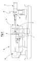
- figure 1 is a schematic view in vertical elevation;
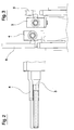
- figure 2 is a partially-sectioned and enlarged view of a part of figure 1 relating to optical devices;
- figure 3 is a schematic front view of the devices of figure 2;
- figure 4 is an enlarged-scale view of a part of figure 1 relating to optical devices, and of the sample arranged on a rest base;
- figure 5 is a schematic view from above of figure 2.
-
- With reference to the figures of the drawings, 1 denotes a rest base for a
sample 2 on which some dilatometric measurements are to be performed, i.e. a measurement (curve) of the dimensional variations induced on the sample when subjected to heating or cooling following a certain law. - The dilatometer further comprises two
optical systems 3 and 4, identifying two optical paths located at a known predetermined reciprocal distance, and able to focus with predetermined magnification on the two ends of thesample 2 arranged on the rest base 1. - The
optical systems 3 and 4 are arranged on planes which are parallel to the rest base 1 so that the first of theoptical systems 3 can focus on one end of the sample, while the second of the optical systems 4 is focused on the other end thereof. More precisely, where the end of the sample is resting on the rest base, the optical system focuses on the line of contact between the rest base and the end of the sample. - The
optical systems 3 and 4 are mechanically independent of one another and are able to move with respect to one another on parallel planes. For thispurpose motors optical systems 3 and 4. - The motor or motors can also cause movement of one or both of the optical systems, both on horizontal parallel planes (displacements in a vertical direction) and on vertical parallel planes (displacements in a horizontal direction), and on horizontal and vertical parallel planes (displacements in vertical and horizontal directions).
- According to the above-described movements chosen, either one or two micrometric screw systems will be provided, combined with the optical system 4, and one only or two micrometric screw systems combined with the
optical system 3. In the figures, and by way of example, only one micrometric screw system is combined to each optical system. - At least one monitoring and measuring device 7 is posteriorly associated to the two
optical systems 3 and 4. The monitoring and measuring device 7 is above to gather focused images from theoptical systems 3 and 4, which are arranged in such a way that the optical paths are arranged on planes which are parallel and perpendicular to the direction of a dilation that is to be measured. The monitoring and measuring device 7 is conformed in such a way as to receive both images taken by the independentoptical systems 3 and 4. The rest base 1 and thesample 2 resting thereon are housed internally of a tubular oven 5, which is structured so as to place thesample 2 on the rest base 1 in perfect view of theoptical systems 3 and 4, especially the end of thesample 2 which constitutes the dimension to be measured. - The
sample 2 is illuminated by a light source 6 located in a diametrically opposite position to theoptical systems 3 and 4, the base 1 being between the source and theoptical systems 3 and 4. The source has the task of illuminating thesample 2 by contrast. - Like in known systems, the
optical systems 3 and 4 comprise: a filter for infrared rays, to eliminate the infrared component emitted by thesample 2 when at a high temperature; a low-transmittance neutral filter to keep the contrast constant throughout the temperature range; a lens constituted by an achromatic duplet lens system having a long focal length, the task of which is to take the image of the inside of the oven and transfer it onto an enlarging device; a microscopic enlarging device which takes the image from the lens and transfers it (enlarged) to the monitoring and measuring device 7. - The monitoring and measuring device 7 can be a CCD interlaced sensor or a progressive scanning sensor, or any image digitizing system.
- The invention can be used for measuring, along two perpendicular directions, dimensional variations induced on a sample by temperature variations, even where the variations occur over very large intervals.
- To carry out the measurements, the
sample 2 is positioned on the rest base 1 located internally of the oven 5 (thesample 2 must be illuminated and both ends should be visible from the outside); the twooptical systems 3 and 4 are focused on the two ends of thesample 2 and, using the monitoring and measuring device 7, the images gathered by theoptical systems 3 and 4 are read and the relative distance between the two images calculated; the effective distance between the two ends of thesample 2 is calculated on the basis of the relative distance between the two images and the distance between the two optical paths of theoptical systems 3 and 4. - The
sample 2 can be positioned vertically on the rest base 1 inside the tubular oven 5, or it can be arranged horizontally in a transversal direction. - The two
optical systems 3 and 4 enable two optical paths to be defined, in ways that will be described in more detail herein below, which paths can focus the images of the ends of thesample 2 under examination. The enlarging of the image can be pushed to the limit of the optical resolution, focusing on only a few hundredths of a millimetre of the upper end of thesample 2 and the lower end thereof, resting on the rest base 1. As the enlarging factor is known, as is the distance between the two optic paths, the length of the sample can be calculated very precisely (to a resolution of 0.5µm). - As mentioned herein above, with this new dilatometer the distance between the two optic paths can be varied, by actuating the motors according to needs and according to the conformation of the dilatometer, in both vertical and horizontal directions, while maintaining the optic paths on parallel planes.
- Supposing that it were decided to measure a dilation in a vertical direction (horizontal dilations are measured in the same way, with obvious differences): it is not necessary to actuate the motors as long as the variation is of limited entity, as the optical systems will be able to maintain sufficient resolution. The optical system 4 will be moved when the dilation of the
sample 2 is great enough to exceed the resolution power of the optical system 4. Obviously, in order to measure the dilation, it will be necessary to take account of the displacement effected, which in any case will simply be added to the measurements made by the monitoring and measuring device 7, inasmuch as the displacement occurs in the same direction as the dilation, and the optical paths are kept on parallel planes. - The motors used enable extremely precise displacements of the optical devices and in any case have error factors so low as to be uninfluential on the dilation measurements. The dilatometer functioning interval is considerably increased with no loss of precision.
- In the dilatometer of the invention, differently to what happens in the previous dilatometer, the
optical systems 3 and 4 are not solidly constrained one to another: the dilations of the rest base for the sample are not automatically compensated. Although the measures are dependent on the variations of the rest base for the sample, these variations are easily readable by theoptical system 3 which focuses the lower end of thesample 2, so the variations can easily be eliminated from the measurement of the dilation of the sample by a simple algebraic sum, without the need for specific preliminary calibrations of the dilatometer. If the variations due to the rest base were of such an entity that they exceeded the resolution power of theoptical system 3, theoptic system 3 could be moved by the motor, so as to refocus the image on the end of the sample connected to the rest base. Obviously, in this case too, it will be necessary to take into account the displacement when evaluating the dilation. As stated above, the dilatometer can be provided with one motor only, associated to the second optical system 4, to increase the range of the dilatometer, and a further motor, associated to the firstoptical system 3, for increasing the temperature range of the dilatometer, which normally causes large variations in the dimensions of the rest base. The dilatometer can also be provided with two further means for moving the optical systems on parallel vertical planes (i.e. in a horizontal direction) in order to measure the transversal dilations of thesample 2. - All of these movements, which as has been mentioned occur while maintaining the optical paths on parallel planes, are exactly measurable and calculable, and influence the measurements taken in a linear direction. Thus they can easily be eliminated from the measurements taken by simple algebraic calculations (which can be done automatically).
Claims (7)
- An improved optical dilatometer, comprising a rest base (1) for a sample (2) to be examined, at least a first and a second optical systems (3, 4), creating two optical paths located at a predetermined distance one from another and able to focus, with a predetermined enlargement, on two ends of the sample (2) housed internally of an oven (5), which oven (5) is structured so as to leave the sample (2) visible to the at least a first and a second optical systems (3, 4); further comprising at least a monitoring and measuring device (7) able to gather images sent by the at least a first and a second optical systems (3, 4); characterised in that: the at least a first and a second optical systems (3, 4) are mechanically independent of one another and are able to move with respect to one another on planes which are parallel to one another; a first motor (8) is provided, of known type, for commandably causing a relative motion between the at least a first and a second optical systems (3, 4).
- The dilatometer of claim 1, characterised in that the optical paths are arranged on parallel planes which are perpendicular to a dilation to be measured.
- The dilatometer of claim 1, characterised in that the first motor (8) comprises at least one micrometric screw system, operated by a step motor, associated to one of the at least a first and a second optical systems (3, 4) and able to displace the one of the at least a first and a second optical systems (3, 4) in an exactly precise and definable way.
- The dilatometer of claim 1, characterised in that the first motor (8) comprises at least one micrometric screw system, operated by a step motor, associated to each of the at least a first and a second optical systems (3, 4) and able to displace each of the at least a first and a second optical systems (3, 4) in an exactly precise and definable way.
- The dilatometer of claim 1, characterised in that the first motor (8) comprises at least two micrometric screw systems, operated by a step motor, associated to each of the at least a first and a second optical systems (3, 4) and able to displace each of the at least a first and a second optical systems (3, 4) in an exactly precise and definable way along two directions, which directions are perpendicular one to another.
- The dilatometer of claim 1, characterised in that each of the at least a first and a second optical systems (3, 4) comprises: a filter for infrared rays, for eliminating an infrared component emitted by the sample (2) when the sample (2) is at a high temperature; a low-transmittance neutral filter, for keeping a contrast constant throughout a temperature interval; a lens constituted by a duplet long-distance focusing achromatic lens for taking an image from inside the oven (5) and transferring the image onto an enlarging device; a microscopic enlarging device, for taking the image from the lens and transferring it in an enlarged state onto a measuring device.
- The dilatometer of claim 6, characterised in that the at least a monitoring and measuring device (7) is constituted by an electronic visualizing device.
Applications Claiming Priority (2)
| Application Number | Priority Date | Filing Date | Title |
|---|---|---|---|
| IT2001MO000248A ITMO20010248A1 (en) | 2001-12-12 | 2001-12-12 | PERFECTED OPTICAL DILATOMETER |
| ITMO20010248 | 2001-12-12 |
Publications (2)
| Publication Number | Publication Date |
|---|---|
| EP1329687A2 true EP1329687A2 (en) | 2003-07-23 |
| EP1329687A3 EP1329687A3 (en) | 2005-08-10 |
Family
ID=11450934
Family Applications (1)
| Application Number | Title | Priority Date | Filing Date |
|---|---|---|---|
| EP02425693A Ceased EP1329687A3 (en) | 2001-12-12 | 2002-11-13 | An improved optical dilatometer |
Country Status (3)
| Country | Link |
|---|---|
| US (1) | US6767127B2 (en) |
| EP (1) | EP1329687A3 (en) |
| IT (1) | ITMO20010248A1 (en) |
Cited By (2)
| Publication number | Priority date | Publication date | Assignee | Title |
|---|---|---|---|---|
| DE10336718B4 (en) * | 2003-08-08 | 2006-08-17 | Krüss GmbH, Wissenschaftliche Laborgeräte | Device for optical measurement of the contours of specimens at high temperatures in a gas-tight sealed tube furnace |
| EP1850123A1 (en) | 2006-04-24 | 2007-10-31 | Bähr-Thermoanalyse GmbH | Optical dilatometer |
Families Citing this family (13)
| Publication number | Priority date | Publication date | Assignee | Title |
|---|---|---|---|---|
| US6960012B1 (en) * | 2002-08-21 | 2005-11-01 | The Sherwin-Williams Company | Method of mixing fluid in F-style container |
| US7025498B2 (en) * | 2003-05-30 | 2006-04-11 | Asml Holding N.V. | System and method of measuring thermal expansion |
| US7224475B2 (en) * | 2004-04-29 | 2007-05-29 | Battelle Energy Alliance, Llc | Methods and apparatus for measurement of a dimensional characteristic and methods of predictive modeling related thereto |
| US7796800B2 (en) * | 2005-01-28 | 2010-09-14 | Hewlett-Packard Development Company, L.P. | Determining a dimensional change in a surface using images acquired before and after the dimensional change |
| CN100538350C (en) * | 2006-07-14 | 2009-09-09 | 中国科学院上海光学精密机械研究所 | Optical fiber grating solid material thermal expansion coefficient testing device |
| TWI438827B (en) * | 2006-09-20 | 2014-05-21 | Univ Illinois | Release strategies for making printable semiconductor structures, devices and device components |
| US8120769B2 (en) * | 2007-08-03 | 2012-02-21 | North Carolina State University | Method and system for fiber properties measurement |
| US9464890B2 (en) * | 2010-09-21 | 2016-10-11 | James L. Arnone | Dynamic data acquisition, and apparatus and methods therefor |
| DE102011051561A1 (en) * | 2011-07-05 | 2013-01-10 | BÄHR-Thermoanalyse GmbH | Dilatometer for the measurement of metallic samples |
| US8992076B2 (en) * | 2010-12-15 | 2015-03-31 | Waters Gmbh | Dilatometer for measuring metallic samples |
| ITPR20130064A1 (en) * | 2013-08-05 | 2015-02-06 | Expert System Solutions S R L | ABSOLUTE OPTICAL FLEXIMETER |
| EP3640623B1 (en) * | 2018-10-19 | 2021-08-25 | Weiss Technik GmbH | Test chamber and method of controlling temperature of test material |
| CN115451796B (en) * | 2022-11-14 | 2023-02-03 | 山东省鲁南地质工程勘察院(山东省地质矿产勘查开发局第二地质大队) | Deformation detection device for dam soil slope |
Citations (3)
| Publication number | Priority date | Publication date | Assignee | Title |
|---|---|---|---|---|
| US4636969A (en) * | 1983-08-15 | 1987-01-13 | Shinagawa Refractories Co., Ltd. | Apparatus for automatic measuring thermal dimensional change |
| US5350899A (en) * | 1992-04-15 | 1994-09-27 | Hiroichi Ishikawa | Semiconductor wafer temperature determination by optical measurement of wafer expansion in processing apparatus chamber |
| EP1199541A2 (en) * | 2000-10-13 | 2002-04-24 | Expert System Solutions S.r.l. | An apparatus for measuring variations in size on bodies subjected to temperature variations |
Family Cites Families (8)
| Publication number | Priority date | Publication date | Assignee | Title |
|---|---|---|---|---|
| US3788746A (en) * | 1972-10-02 | 1974-01-29 | Hewlett Packard Co | Optical dilatometer |
| US4930894A (en) * | 1984-04-27 | 1990-06-05 | Hewlett-Packard Company | Minimum deadpath interferometer and dilatometer |
| DE3514000A1 (en) * | 1985-04-18 | 1986-10-23 | Ingenieurbüro Dölling & Neubert, 3392 Clausthal-Zellerfeld | Dilatometer operating in a contactless fashion |
| US4762424A (en) * | 1985-05-22 | 1988-08-09 | Theta Industries, Inc. | Low temperature dilatometer |
| US4924477A (en) * | 1989-01-24 | 1990-05-08 | Eastman Kodak Company | Assembly and method for determining the coefficient of thermal expansion of a workpiece |
| US5479261A (en) * | 1991-05-29 | 1995-12-26 | Honeywell Inc. | Readout system for dilatometers |
| US5231285A (en) * | 1991-06-28 | 1993-07-27 | Honeywell Inc. | Refraction index change measurement |
| US6175416B1 (en) * | 1996-08-06 | 2001-01-16 | Brown University Research Foundation | Optical stress generator and detector |
-
2001
- 2001-12-12 IT IT2001MO000248A patent/ITMO20010248A1/en unknown
-
2002
- 2002-11-13 EP EP02425693A patent/EP1329687A3/en not_active Ceased
- 2002-11-14 US US10/293,342 patent/US6767127B2/en not_active Expired - Lifetime
Patent Citations (3)
| Publication number | Priority date | Publication date | Assignee | Title |
|---|---|---|---|---|
| US4636969A (en) * | 1983-08-15 | 1987-01-13 | Shinagawa Refractories Co., Ltd. | Apparatus for automatic measuring thermal dimensional change |
| US5350899A (en) * | 1992-04-15 | 1994-09-27 | Hiroichi Ishikawa | Semiconductor wafer temperature determination by optical measurement of wafer expansion in processing apparatus chamber |
| EP1199541A2 (en) * | 2000-10-13 | 2002-04-24 | Expert System Solutions S.r.l. | An apparatus for measuring variations in size on bodies subjected to temperature variations |
Non-Patent Citations (1)
| Title |
|---|
| BERNUTH W ET AL: "LASEROPTISCHES ZWEIKOORDINATEN-DEHNUNGSMESSGERAET" TECHNISCHES MESSEN TM, R.OLDENBOURG VERLAG. MUNCHEN, DE, vol. 59, no. 11, 1 November 1992 (1992-11-01), pages 436-442, XP000321277 ISSN: 0171-8096 * |
Cited By (3)
| Publication number | Priority date | Publication date | Assignee | Title |
|---|---|---|---|---|
| DE10336718B4 (en) * | 2003-08-08 | 2006-08-17 | Krüss GmbH, Wissenschaftliche Laborgeräte | Device for optical measurement of the contours of specimens at high temperatures in a gas-tight sealed tube furnace |
| EP1850123A1 (en) | 2006-04-24 | 2007-10-31 | Bähr-Thermoanalyse GmbH | Optical dilatometer |
| US7524105B2 (en) | 2006-04-24 | 2009-04-28 | Baehr - Thermoanalyse Gmbh | Optical dilatometer |
Also Published As
| Publication number | Publication date |
|---|---|
| EP1329687A3 (en) | 2005-08-10 |
| ITMO20010248A1 (en) | 2003-06-12 |
| US6767127B2 (en) | 2004-07-27 |
| US20030108082A1 (en) | 2003-06-12 |
| ITMO20010248A0 (en) | 2001-12-12 |
Similar Documents
| Publication | Publication Date | Title |
|---|---|---|
| US6767127B2 (en) | Optical dilatometer | |
| US4636969A (en) | Apparatus for automatic measuring thermal dimensional change | |
| Huang et al. | Portable laser scanner for measuring soil surface roughness | |
| CN101107558B (en) | Tracking auto focus system | |
| US5601364A (en) | Method and apparatus for measuring thermal warpage | |
| US9081028B2 (en) | Scanning probe microscope with improved feature location capabilities | |
| JP5942847B2 (en) | Height measuring method and height measuring apparatus | |
| JPH01245104A (en) | Microscope having device for measuring microscopic construction | |
| US6476922B2 (en) | Apparatus for measuring variations in size on bodies subjected to temperature variations | |
| US4359282A (en) | Optical measuring method and apparatus | |
| US5088827A (en) | Measuring apparatus for determining the dimension and position of an elongate object | |
| CN1570550A (en) | Three dimensional high precision multifunctional thermal deformation experimental apparatus | |
| JP2006129473A (en) | Method and apparatus for correction of nonlinear field of view distortion of digital imaging system | |
| JP2013034127A (en) | Imaging apparatus | |
| CN1069133C (en) | Non-contact measuring method and equipment of thermal expansion coefficient | |
| JP2017078705A (en) | Method for measuring at least one dimension of object | |
| JPS6211105A (en) | Optical measuring method and device thereof | |
| CN113884533A (en) | Optical measurement method and device for linear expansion coefficient of metal | |
| US20090059243A1 (en) | Method for determining the absolute thickness of non-transparent and transparent samples by means of confocal measurement technology | |
| CN115046479B (en) | Superlens detection device and system | |
| Ruffino et al. | New opto-electronic dilatometer | |
| CN110375677B (en) | Device and method for detecting included angle between pointing direction of camera detector and installation surface of focal plane component | |
| JPS6039540A (en) | Measuring device of coefficient of thermal expansion | |
| Wang et al. | A contactless CCD dilatometer for foil materials | |
| JP2686770B2 (en) | Micro dimension measurement X-ray equipment |
Legal Events
| Date | Code | Title | Description |
|---|---|---|---|
| PUAI | Public reference made under article 153(3) epc to a published international application that has entered the european phase |
Free format text: ORIGINAL CODE: 0009012 |
|
| AK | Designated contracting states |
Designated state(s): AT BE BG CH CY CZ DE DK EE ES FI FR GB GR IE IT LI LU MC NL PT SE SK TR |
|
| AX | Request for extension of the european patent |
Extension state: AL LT LV MK RO SI |
|
| PUAL | Search report despatched |
Free format text: ORIGINAL CODE: 0009013 |
|
| AK | Designated contracting states |
Kind code of ref document: A3 Designated state(s): AT BE BG CH CY CZ DE DK EE ES FI FR GB GR IE IT LI LU MC NL PT SE SK TR |
|
| AX | Request for extension of the european patent |
Extension state: AL LT LV MK RO SI |
|
| RIC1 | Information provided on ipc code assigned before grant |
Ipc: 7G 01N 25/16 B Ipc: 7G 01B 11/16 A |
|
| 17P | Request for examination filed |
Effective date: 20050912 |
|
| AKX | Designation fees paid |
Designated state(s): AT BE BG CH CY CZ DE DK EE ES FI FR GB GR IE IT LI LU MC NL PT SE SK TR |
|
| 17Q | First examination report despatched |
Effective date: 20070323 |
|
| STAA | Information on the status of an ep patent application or granted ep patent |
Free format text: STATUS: THE APPLICATION HAS BEEN REFUSED |
|
| 18R | Application refused |
Effective date: 20110513 |