EP1335390A2 - Communication cables with oppositely twinned and bunched insulated conductors - Google Patents
Communication cables with oppositely twinned and bunched insulated conductors Download PDFInfo
- Publication number
- EP1335390A2 EP1335390A2 EP03003053A EP03003053A EP1335390A2 EP 1335390 A2 EP1335390 A2 EP 1335390A2 EP 03003053 A EP03003053 A EP 03003053A EP 03003053 A EP03003053 A EP 03003053A EP 1335390 A2 EP1335390 A2 EP 1335390A2
- Authority
- EP
- European Patent Office
- Prior art keywords
- pairs
- communications cable
- cable
- conductors
- rotative direction
- Prior art date
- Legal status (The legal status is an assumption and is not a legal conclusion. Google has not performed a legal analysis and makes no representation as to the accuracy of the status listed.)
- Granted
Links
- 239000004020 conductor Substances 0.000 title claims abstract description 85
- 238000004891 communication Methods 0.000 title claims abstract description 41
- 239000013047 polymeric layer Substances 0.000 claims abstract description 5
- 239000000463 material Substances 0.000 claims description 33
- -1 polyethylene Polymers 0.000 claims description 14
- 239000010410 layer Substances 0.000 claims description 11
- 238000000034 method Methods 0.000 claims description 10
- 239000004698 Polyethylene Substances 0.000 claims description 9
- 229920000573 polyethylene Polymers 0.000 claims description 8
- 125000006850 spacer group Chemical group 0.000 claims description 8
- 238000009413 insulation Methods 0.000 claims description 7
- 238000004519 manufacturing process Methods 0.000 claims description 4
- 239000007787 solid Substances 0.000 claims description 4
- 239000012212 insulator Substances 0.000 abstract description 21
- 239000004812 Fluorinated ethylene propylene Substances 0.000 description 8
- 229920009441 perflouroethylene propylene Polymers 0.000 description 8
- 239000004800 polyvinyl chloride Substances 0.000 description 6
- 229920000915 polyvinyl chloride Polymers 0.000 description 6
- 229920002313 fluoropolymer Polymers 0.000 description 5
- RNFJDJUURJAICM-UHFFFAOYSA-N 2,2,4,4,6,6-hexaphenoxy-1,3,5-triaza-2$l^{5},4$l^{5},6$l^{5}-triphosphacyclohexa-1,3,5-triene Chemical compound N=1P(OC=2C=CC=CC=2)(OC=2C=CC=CC=2)=NP(OC=2C=CC=CC=2)(OC=2C=CC=CC=2)=NP=1(OC=1C=CC=CC=1)OC1=CC=CC=C1 RNFJDJUURJAICM-UHFFFAOYSA-N 0.000 description 4
- 239000003063 flame retardant Substances 0.000 description 4
- 239000006260 foam Substances 0.000 description 4
- 239000004743 Polypropylene Substances 0.000 description 3
- 239000000956 alloy Substances 0.000 description 3
- 229910045601 alloy Inorganic materials 0.000 description 3
- 229920001577 copolymer Polymers 0.000 description 3
- 239000011810 insulating material Substances 0.000 description 3
- 239000000203 mixture Substances 0.000 description 3
- 229920001155 polypropylene Polymers 0.000 description 3
- BFKJFAAPBSQJPD-UHFFFAOYSA-N tetrafluoroethene Chemical group FC(F)=C(F)F BFKJFAAPBSQJPD-UHFFFAOYSA-N 0.000 description 3
- BZPCMSSQHRAJCC-UHFFFAOYSA-N 1,2,3,3,4,4,5,5,5-nonafluoro-1-(1,2,3,3,4,4,5,5,5-nonafluoropent-1-enoxy)pent-1-ene Chemical compound FC(F)(F)C(F)(F)C(F)(F)C(F)=C(F)OC(F)=C(F)C(F)(F)C(F)(F)C(F)(F)F BZPCMSSQHRAJCC-UHFFFAOYSA-N 0.000 description 2
- RYGMFSIKBFXOCR-UHFFFAOYSA-N Copper Chemical compound [Cu] RYGMFSIKBFXOCR-UHFFFAOYSA-N 0.000 description 2
- 239000004809 Teflon Substances 0.000 description 2
- 229920006362 Teflon® Polymers 0.000 description 2
- XAGFODPZIPBFFR-UHFFFAOYSA-N aluminium Chemical compound [Al] XAGFODPZIPBFFR-UHFFFAOYSA-N 0.000 description 2
- 229910052782 aluminium Inorganic materials 0.000 description 2
- 238000010276 construction Methods 0.000 description 2
- 238000012986 modification Methods 0.000 description 2
- 230000004048 modification Effects 0.000 description 2
- 239000002861 polymer material Substances 0.000 description 2
- 238000012360 testing method Methods 0.000 description 2
- BLTXWCKMNMYXEA-UHFFFAOYSA-N 1,1,2-trifluoro-2-(trifluoromethoxy)ethene Chemical compound FC(F)=C(F)OC(F)(F)F BLTXWCKMNMYXEA-UHFFFAOYSA-N 0.000 description 1
- 229920001780 ECTFE Polymers 0.000 description 1
- 229920007925 Ethylene chlorotrifluoroethylene (ECTFE) Polymers 0.000 description 1
- 239000006057 Non-nutritive feed additive Substances 0.000 description 1
- 229910000831 Steel Inorganic materials 0.000 description 1
- 239000000370 acceptor Substances 0.000 description 1
- 239000002253 acid Substances 0.000 description 1
- 239000000654 additive Substances 0.000 description 1
- 229910000410 antimony oxide Inorganic materials 0.000 description 1
- 239000011230 binding agent Substances 0.000 description 1
- 230000005540 biological transmission Effects 0.000 description 1
- 229910052802 copper Inorganic materials 0.000 description 1
- 239000010949 copper Substances 0.000 description 1
- 239000003989 dielectric material Substances 0.000 description 1
- 230000009977 dual effect Effects 0.000 description 1
- 238000011156 evaluation Methods 0.000 description 1
- 238000001125 extrusion Methods 0.000 description 1
- 229920005570 flexible polymer Polymers 0.000 description 1
- 238000005187 foaming Methods 0.000 description 1
- 238000009434 installation Methods 0.000 description 1
- 239000012811 non-conductive material Substances 0.000 description 1
- 239000002667 nucleating agent Substances 0.000 description 1
- VTRUBDSFZJNXHI-UHFFFAOYSA-N oxoantimony Chemical compound [Sb]=O VTRUBDSFZJNXHI-UHFFFAOYSA-N 0.000 description 1
- 239000000049 pigment Substances 0.000 description 1
- 229920000642 polymer Polymers 0.000 description 1
- 230000008054 signal transmission Effects 0.000 description 1
- 239000010959 steel Substances 0.000 description 1
- 239000003017 thermal stabilizer Substances 0.000 description 1
Images


Classifications
-
- H—ELECTRICITY
- H01—ELECTRIC ELEMENTS
- H01B—CABLES; CONDUCTORS; INSULATORS; SELECTION OF MATERIALS FOR THEIR CONDUCTIVE, INSULATING OR DIELECTRIC PROPERTIES
- H01B11/00—Communication cables or conductors
- H01B11/005—Quad constructions
Definitions
- the present invention relates broadly to communications cable and, more particularly, to communications cable containing at least one twisted pair of insulated conductors.
- Insulated conductors such as those used in communications cable are often provided as twisted pairs of insulated conductors having two insulated conductors twisted, or "twinned", about each other to form a dual conductor group.
- a typical assembly for these communications cables comprises two or more twisted pairs of insulated conductors "bunched” together ( i.e ., further twisted and in some instances captured with a binder thread or cable) and contained in a cable jacket.
- the twisting and bundling of the conductors can facilitate the installation of the cable and connection between insulated conductors. Twisted pair conductors are commonly used in applications such as local area network (LAN) cables and wireless cable network architectures.
- LAN local area network
- Crosstalk can occur between twisted pairs of insulated conductors that can negatively affect the signals transmitted by these conductors.
- Crosstalk may especially present a problem in high frequency applications because crosstalk may increase logarithmically as the frequency of the transmission increases.
- Some twisted pairs are sufficiently impacted by crosstalk that insulating spacers are positioned between pairs within the same cable. See, e.g., U.S. Patent No. 5,969,295 to Boucino et al.
- Another technique for adjusting crosstalk performance involves twinning the conductors of different pairs so that they have different lay lengths and carefully selecting the lay length for bunching.
- the insulation employed for conductors is typically a polymeric material.
- Exemplary insulating materials include , but are not limited to , polyvinylchloride, polyvinylchloride alloys, polyethylene, polypropylene, and flame retardant materials such as fluorinated polymers.
- Exemplary fluorinated polymers include but are not limited to, fluorinated ethylene-propylene (FEP), ethylenetrifluoroethylene (ETFE), ethylene chlorotrifluoroethylene (ECTFE), perfluoroalkoxypolymers (PFA's) like tetrafluoroethylene and perfluoropropylvinylether ( e.g. , Teflon PFA 340), and mixtures thereof.
- FEP fluorinated ethylene-propylene
- ETFE ethylenetrifluoroethylene
- ECTFE ethylene chlorotrifluoroethylene
- PFA's perfluoroalkoxypolymers
- a communications cable comprises: an elongate cable jacket having an internal cavity; and a plurality of twisted pairs of insulated conductors disposed in the internal cavity of the cable jacket, each of the conductors being insulated with a polymeric layer.
- Each of the insulated conductors within each of the twisted pairs of conductors defines a twinning helix having a first rotative direction, and each of the twisted pairs defines a bunching helix having a second rotative direction, the second rotative direction being opposite that of the first rotative direction.
- the communications cable can provide acceptable crosstalk and attenuation performance, even with foamed insulators that have demonstrated unacceptable performance when twinned and bunched in the same rotative direction.
- At least one, and more preferably all, of the polymeric layers are formed of a foamed polymeric material(as used herein, a "foamed" polymeric material means both foamed and foam skin materials). It is also preferred that the twinning helices have different lay lengths, and the bunching helix also has a different lay length.
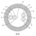
- a twinned pair cable designated broadly at 20, is illustrated in Figures 1, 2A and 2B.
- the cable 20 comprises two twinned pairs 22, 28 of conductors, with the first pair 22 including conductors 24, 26 and the second pair 28 including conductors 30, 32.
- the conductors 24, 26, 30, 32 are covered with, respectively, insulators 25, 27, 31, 33.
- the conductors 24, 26, 30, 32 may be a metallic wire of any of the well-known metallic conductors used in wire and cable applications, such as copper, aluminum, copper-clad aluminum and/or copper-clad steel.
- the wire is 18 to 26 AWG gauge.
- Suitable insulating materials for the insulators 25, 27, 31, 33 include polyvinylchloride, polyvinylchloride alloys, polyethylene, polypropylene, and flame retardant materials such as fluorinated polymers.
- Exemplary fluorinated polymers for use in the invention include FEP, ETFE, ECTFE, PFA's, and mixtures thereof.
- Exemplary PFA's include copolymers of tetrafluoroethylene and perfluoropropylvinylether (e.g ., Teflon PFA 340) and copolymers of tetrafluoroethylene and perfluoromethylvinylether (MFA copolymers, which are available from Ausimont S.p.A.).
- the material of the insulators 25, 27, 31, 33 may contain conventional additives such as pigments, nucleating agents, thermal stabilizers, acid acceptors, processing aids, and/or flame retardant compositions (e.g ., antimony oxide). If desired, the insulating material may not be the same for each twisted pair 22, 28.
- some or all of the insulators 25, 27, 31, 33 may be formed of polymeric materials that have been foamed or that have a foam skin structure, such as FEP or polyethylene. Typically, these materials are foamed to a density of between about 50 and 80 percent of their solid volume.
- the conductors 24, 26 of the pair 22 are twinned about a twin axis T1 and follow a counterclockwise twinning helix when viewed from the viewing direction indicated in Figure 1 and from the vantage point of Figures 2A-2B .
- the conductors 30, 32 of the pair 28 are twinned about a twin axis T2 and follow a counterclockwise twinning helix when view from the viewing direction indicated in Figure 1 and from the vantage point of Figures 2A-2B .
- the pairs 22, 28 are bunched about a bunching axis B1 and follow a clockwise bunching helix when viewed from the viewing direction indicated in Figure 1 and from the vantage point of Figures 2A-2B. It has been discovered that, when conductors with insulation are helically twinned in one rotative direction and helically bunched in the opposite rotative direction, there can be reduced crushing of the insulators 25, 27, 31, 33 without the expected corresponding reduction in cross-talk performance.
- the pairs 22, 28 are twinned such that the "lay length" (defined as the distance along each conductor required for the conductor to travel one complete circumference of the helix) of twinning is between about 0.25 and 1.0 inches. In some embodiments, the lay lengths of the pairs 22, 28 will differ from one another (usually by about 20 to 50 percent). The pairs 22, 28 are typically bunched so that the lay length of bunching is between about 2.5 and 6.0 inches.
- cables can also be constructed with pairs being twinned in a clockwise helix and bunched in a counterclockwise helix.
- the jacket 34 is made of a flexible polymer material and is formed by melt extrusion.
- any of the polymer materials conventionally used in cable construction may be suitably employed; these include, but are not limited to, polyvinylchloride, polyvinylchloride alloys, polyethylene, polypropylene and flame retardant materials such as FEP or another fluorinated polymer.
- other materials and/or fabrication methods may be used.
- the cable jacket 34 is extruded to a thickness of between 15 and 25 mils (thousandths of an inch), which may facilitate stripping the cable jacket 34 away from the twisted pairs 22, 28.
- the jacket may overlie one or more optional shielding layers 36 ; these are typically formed of a wide variety of known conductive and/or nonconductive materials such as nonconductive polymeric tape, conductive tape, braid, a combination of nonconductive polymeric tape, conductive tape and/or braid, and/or other such materials as will be understood to one of skill in the art using conventional fabrication techniques.
- the cable 20 may be used in a variety of computer, communication, and telecommuncation environments, including residential and commercial buildings.
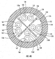
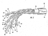
- the cable 50 includes four twisted conductor pairs 52, 58, 64, 70 , which comprise, respectively, conductors 54 and 56 (insulated by insulators 55 and 57 ), conductors 60 and 62 (insulated by insulators 61 and 63 ), conductors 66 and 68 (insulated by insulators 67 and 69 ), and conductors 72 and 74 (insulated by insulators 73 and 75 ).
- the pairs 52, 58, 64, 70 are covered by a jacket 76 and an optional shielding layer 78 .
- the description of the materials appropriate for use in the conductors, insulators, jacket and shield of the cable 20 are equally applicable to these components of the cable 50 and need not be repeated here.
- the pairs 52, 58, 64, 70 are twinned such that they form clockwise helices along their respective twinning axes T3, T4, T5, T6 , and are bunched such that they form counterclockwise helices along the bunching axis B2 .
- Lay lengths of the twinning and bunching helices are as described above for the cable 20 .
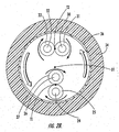
- a further cable embodiment of the present invention, designated broadly at 150, is illustrated in Figures 3, 4A and 4B .
- the cable 150 includes four twisted conductor pairs 152, 158, 164, 170 which comprise, respectively, conductors 154 and 156 (insulated by insulators 155 and 157 ), conductors 160 and 162 (insulated by insulators 161 and 163 ), conductors 166 and 168 (insulated by insulators 167 and 169 ), and conductors 172 and 174 (insulated by insulators 173 and 175 ).
- the cable 150 also includes a jacket 176 and an optional shielding layer 178 .
- the discussions hereinabove regarding the materials and construction of the conductors, insulators, jacket and shield layers are equally applicable to the cable 150 and need-not be repeated here.
- the cable 150 also includes a spacer 151 that extends the length of the cable 150 and separates the internal cavity of the cable 150 into four compartments 153a, 153b, 153c, 153d. Each of the pairs 152, 158, 164, 170 resides in a respective one of the compartments 153a, 153b, 153c, 153d.
- the spacer 151 is typically included in a cable in order to regulate the distance between twisted pairs, which in turn can render crosstalk performance more consistent. Suitable different spacer configurations and materials are discussed in detail in U.S. Patent No. 5,789,711 to Gaeris et al., U.S. Patent No. 5,969,295 to Boucino et al. and co-pending and co-assigned U.S. Patent Application No. 09/591,349, filed June 9, 2000 and entitled Communications Cables with Isolators; the contents of each of these documents are hereby incorporated herein by reference in their entireties.
- each cable was twinned in a counterclockwise direction at a lay length of between 0.45 and 0.8 inches.
- One cable (Cable 1) was bunched in a clockwise direction at a lay length of 6 inches (such that the twinning and bunching were in opposite rotative directions), and the other cable (Cable 2) was bunched in a counterclockwise direction at a lay length of 6 inches (such that twinning and bunching were in the same rotative direction).
- the cables were evaluated under testing conditions set forth in ASTM-D4566-2000.
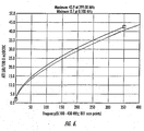
- Figures 6 and 7 are graphs illustrating the performance of Cable 1.
- Figure 6 is a plot of cable attenuation as a function of frequency of Cable 1 and the permissible attenuation per specification.
- Figure 6 demonstrates that the plot of Cable 1 falls below the specification ( i.e. , is acceptable) for attenuation performance.
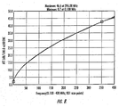
- Figure 7 is a plot of near end crosstalk as a function of frequency for Cable 1 and specification.
- Figure 7 shows that the plot for Cable lis positioned above the specification curve, thereby indicating acceptable performance.
Abstract
Description
- The present invention relates broadly to communications cable and, more particularly, to communications cable containing at least one twisted pair of insulated conductors.
- Insulated conductors such as those used in communications cable are often provided as twisted pairs of insulated conductors having two insulated conductors twisted, or "twinned", about each other to form a dual conductor group. A typical assembly for these communications cables comprises two or more twisted pairs of insulated conductors "bunched" together (i.e., further twisted and in some instances captured with a binder thread or cable) and contained in a cable jacket. The twisting and bundling of the conductors can facilitate the installation of the cable and connection between insulated conductors. Twisted pair conductors are commonly used in applications such as local area network (LAN) cables and wireless cable network architectures.
- One problem associated with communications cable produced with the conventional twisted pair assembly is that crosstalk can occur between twisted pairs of insulated conductors that can negatively affect the signals transmitted by these conductors. Crosstalk may especially present a problem in high frequency applications because crosstalk may increase logarithmically as the frequency of the transmission increases. Some twisted pairs are sufficiently impacted by crosstalk that insulating spacers are positioned between pairs within the same cable. See, e.g., U.S. Patent No. 5,969,295 to Boucino et al. Another technique for adjusting crosstalk performance involves twinning the conductors of different pairs so that they have different lay lengths and carefully selecting the lay length for bunching.
- The insulation employed for conductors is typically a polymeric material. Exemplary insulating materials include, but are not limited to, polyvinylchloride, polyvinylchloride alloys, polyethylene, polypropylene, and flame retardant materials such as fluorinated polymers. Exemplary fluorinated polymers, include but are not limited to, fluorinated ethylene-propylene (FEP), ethylenetrifluoroethylene (ETFE), ethylene chlorotrifluoroethylene (ECTFE), perfluoroalkoxypolymers (PFA's) like tetrafluoroethylene and perfluoropropylvinylether (e.g., Teflon PFA 340), and mixtures thereof.
- In an effort to reduce the weight and cost of insulation, conductors with foamed polymer insulation, and particularly foamed FEP insulation, have been constructed. The foaming process introduces air into the dielectric medium. Air having a lower dielectric constant increases the velocity of propagation (Vp). Higher Vp typically translates to improved signal transmission speed for high speed data or communications systems. However, the resulting foamed medium tends to become more susceptible to crushing during the twinning and bunching processes. Such crushing can undesirably raise the capacitance and lower the impedance of the finished cable, which can consequently degrade attenuation performance. In order to provide foamed dielectric insulation with sufficient crush resistance to provide adequate cable performance, additional dielectric material has been required, thereby negating some or all of the weight, cost and performance advantages of using a foamed dielectric. Accordingly, it would be desirable to provide a cable having a foamed dielectric with acceptable performance properties while reducing material weight and cost.
- The present invention is directed to a communications cable and an associated manufacturing method therefore that can utilize foamed insulators for electrical conductors and still provide acceptable performance. According to certain embodiments of the invention, a communications cable comprises: an elongate cable jacket having an internal cavity; and a plurality of twisted pairs of insulated conductors disposed in the internal cavity of the cable jacket, each of the conductors being insulated with a polymeric layer. Each of the insulated conductors within each of the twisted pairs of conductors defines a twinning helix having a first rotative direction, and each of the twisted pairs defines a bunching helix having a second rotative direction, the second rotative direction being opposite that of the first rotative direction. In this configuration, the communications cable can provide acceptable crosstalk and attenuation performance, even with foamed insulators that have demonstrated unacceptable performance when twinned and bunched in the same rotative direction.
- It is preferred that at least one, and more preferably all, of the polymeric layers are formed of a foamed polymeric material(as used herein, a "foamed" polymeric material means both foamed and foam skin materials). It is also preferred that the twinning helices have different lay lengths, and the bunching helix also has a different lay length.
-
- Figure 1 is a perspective cutaway view of an embodiment of a twinned pair cable of the present invention.
- Figure 2A is a section view of the cable of Figure 1 taken along
lines 2A―2A thereof. - Figure 2B is a section view of the cable of Figure 1 taken along
lines 2B―2B thereof. - Figure 3 is a perspective cutaway view of another embodiment of a twinned pair cable of the present invention, wherein the cable includes an insulating spacer.
- Figure 4A is a section view of the cable of Figure 3 taken along
lines 4A―4A thereof. - Figure 4B is a section view of the cable of Figure 3 taken along
lines 4B―4B thereof. - Figure 5 is a perspective cutaway view of another embodiment of a twinned pair cable of the present invention.
- Figure 6 is a graph plotting attenuation as a function of frequency for a cable sample twinned in a counterclockwise direction and bunched in a clockwise direction.
- Figure 7 is a graph plotting near end crosstalk as a function of frequency for a cable sample twinned in a counterclockwise direction and bunched in a clockwise direction.
- Figure 8 is a graph plotting attenuation as a function of frequency for a cable sample twinned in a counterclockwise direction and bunched in a counterclockwise direction.
- Figure 9 is a graph plotting near end crosstalk as a function of frequency for a cable sample twinned in a counterclockwise direction and bunched in a counterclockwise direction.
-
- The present invention now will be described more fully hereinafter with reference to the accompanying drawings, in which preferred embodiments of the invention are shown. This invention may, however, be embodied in many different forms and should not be construed as limited to the embodiments set forth herein. Instead, these embodiments are provided so that this disclosure will be thorough and complete, and will fully convey the scope of the invention to those skilled in the art. It will be understood that when an element (e.g., cable jacket) is referred to as being "connected to" another element, it can be directly connected to the other element or intervening elements may also be present. In contrast, when an element is referred to as being "directly connected to" another element, there are no intervening elements present. Like numbers refer to like elements throughout. Some dimensions and thicknesses may be exaggerated for clarity.
- Referring now to the figures, a twinned pair cable, designated broadly at 20, is illustrated in Figures 1, 2A and 2B. The
cable 20 comprises twotwinned pairs first pair 22 includingconductors second pair 28 includingconductors conductors insulators conductors - Suitable insulating materials for the
insulators insulators twisted pair insulators - As illustrated in Figures 1, 2A and 2B, the
conductors pair 22 are twinned about a twin axis T1 and follow a counterclockwise twinning helix when viewed from the viewing direction indicated in Figure 1 and from the vantage point of Figures 2A-2B. Likewise, theconductors pair 28 are twinned about a twin axis T2 and follow a counterclockwise twinning helix when view from the viewing direction indicated in Figure 1 and from the vantage point of Figures 2A-2B. However, thepairs insulators - Typically, the
pairs pairs pairs - Those skilled in this art will recognize that, although the
cable 20 is illustrated withpairs - The
pairs cavity 35 of ajacket 34. Preferably, thejacket 34 is made of a flexible polymer material and is formed by melt extrusion. As will be understood by those of skill in the art, any of the polymer materials conventionally used in cable construction may be suitably employed; these include, but are not limited to, polyvinylchloride, polyvinylchloride alloys, polyethylene, polypropylene and flame retardant materials such as FEP or another fluorinated polymer. Moreover, other materials and/or fabrication methods may be used. Preferably, thecable jacket 34 is extruded to a thickness of between 15 and 25 mils (thousandths of an inch), which may facilitate stripping thecable jacket 34 away from thetwisted pairs - The
cable 20 may be used in a variety of computer, communication, and telecommuncation environments, including residential and commercial buildings. - Another cable embodiment of the present invention, designated broadly at 50, is illustrated in Figure 5. The
cable 50 includes four twisted conductor pairs 52, 58, 64, 70, which comprise, respectively,conductors 54 and 56 (insulated by insulators 55 and 57),conductors 60 and 62 (insulated byinsulators 61 and 63),conductors 66 and 68 (insulated by insulators 67 and 69), andconductors 72 and 74 (insulated byinsulators 73 and 75). Like thecable 20 illustrated in Figures 1, 2A and 2B, thepairs jacket 76 and anoptional shielding layer 78. The description of the materials appropriate for use in the conductors, insulators, jacket and shield of thecable 20 are equally applicable to these components of thecable 50 and need not be repeated here. - The
pairs cable 20. - A further cable embodiment of the present invention, designated broadly at 150, is illustrated in Figures 3, 4A and 4B. The
cable 150 includes four twisted conductor pairs 152, 158, 164, 170 which comprise, respectively,conductors 154 and 156 (insulated byinsulators 155 and 157),conductors 160 and 162 (insulated byinsulators 161 and 163),conductors 166 and 168 (insulated byinsulators 167 and 169), andconductors 172 and 174 (insulated byinsulators 173 and 175). Thecable 150 also includes ajacket 176 and anoptional shielding layer 178. The discussions hereinabove regarding the materials and construction of the conductors, insulators, jacket and shield layers are equally applicable to thecable 150 and need-not be repeated here. - Unlike the
cable 50, thecable 150 also includes a spacer 151 that extends the length of thecable 150 and separates the internal cavity of thecable 150 into fourcompartments pairs compartments - The invention will now be described in great detail in the following non-limiting example.
- Testing was conducted comparing the performance of cables employing oppositely twinned and bunched conductors with cables having similarly twinned and bunched conductors.
- Two cable samples were constructed, each having four twisted pairs of insulated conductors and having the specifications set forth in Table 1.
Property Value Conductor Dimensions 24 gauge Conductor Material AWG copper wire Insulator Material 3 pairs foam/skin FEP; 1 pair foam/skin PE Insulator Thickness 0.007 in Insulator Coaxial Capacitance FEP 52 min., 57 max; PE 61 (pf/ft) Cable Length 328 ft Jacket Material PVC Alloy (plenum rated) - The twisted pairs of each cable were twinned in a counterclockwise direction at a lay length of between 0.45 and 0.8 inches. One cable (Cable 1) was bunched in a clockwise direction at a lay length of 6 inches (such that the twinning and bunching were in opposite rotative directions), and the other cable (Cable 2) was bunched in a counterclockwise direction at a lay length of 6 inches (such that twinning and bunching were in the same rotative direction). The cables were evaluated under testing conditions set forth in ASTM-D4566-2000.
- Results of the evaluations are set forth in Figures 6-9. Figures 6 and 7 are graphs illustrating the performance of Cable 1. Figure 6 is a plot of cable attenuation as a function of frequency of Cable 1 and the permissible attenuation per specification. Figure 6 demonstrates that the plot of Cable 1 falls below the specification (i.e., is acceptable) for attenuation performance. Figure 7 is a plot of near end crosstalk as a function of frequency for Cable 1 and specification. Figure 7 shows that the plot for Cable lis positioned above the specification curve, thereby indicating acceptable performance. These results compare favorably to Figures 8 and 9, which show that Cable 2, while having acceptable crosstalk performance, was not able to meet the specification for attenuation.
- The foregoing is illustrative of the present invention and is not to be construed as limiting thereof. Although a few exemplary embodiments of this invention have been described, those skilled in the art will readily appreciate that many modifications are possible in the exemplary embodiments without materially departing from the novel teachings and advantages of this invention. Accordingly, all such modifications are intended to be included within the scope of this invention as defined in the claims. The invention is defined by the following claims, with equivalents of the claims to be included therein.
Claims (32)
- A communications cable, comprising:wherein each of the insulated conductors within each of the twisted pairs of conductors defines a twinning helix having a first rotative direction; andan elongate cable jacket having an internal cavity; anda plurality of twisted pairs of insulated conductors disposed in the internal cavity of the cable jacket, each of the conductors being insulated with a polymeric layer;
wherein each of the twisted pairs defines a bunching helix having a second rotative direction, the second rotative direction being opposite that of the first rotative direction. - The communications cable defined in Claim 1, wherein each of the polymeric layers is formed of a foamed polymeric material.
- The communications cable defined in Claim 2, wherein the polymeric material is selected from the group consisting of FEP and polyethylene.
- The communications cable defined in Claim 2, wherein the foamed polymeric material is foamed to a density of between about 50 and 80 percent of that of the solid polymeric material.
- The communications cable defined in Claim 1, wherein the plurality of twisted pairs of insulated conductors comprises four pairs of insulated conductors.
- The communications cable defined in Claim 1, wherein lay lengths of the twinning helices defined by the insulated conductors are between about 0.25 and 1.0 inches.
- The communications cable defined in Claim 6, wherein a lay length of the bunching helix is between about 2.5 and 8.0 inches.
- The communications cable defined in Claim 1, wherein each of the twinning helices has a different lay length.
- The communications cable defined in Claim 1, further comprising an elongate spacer that divides the internal cavity into compartments, each of the twinned pairs of cable residing in a separate compartment.
- The communications cable defined in Claim 1, further comprising a shield layer underlying the cable jacket.
- A communications cable, comprising:wherein each of the insulated conductors within each of the twisted pairs of conductors defines a twinning helix having a first rotative direction, each of the twinning helices having a different lay length; andan elongate cable jacket having an internal cavity; anda plurality of twisted pairs of insulated conductors disposed in the internal cavity of the cable jacket, each of the conductors being insulated with a polymeric layer;
wherein each of the twisted pairs defines a bunching helix having a second rotative direction, the second rotative direction being opposite that of the first rotative direction, the bunching helix having a different lay length than any of those of the twinning helices. - The communications cable defined in Claim 11, wherein at least one of the polymeric layers is formed of a foamed polymeric material.
- The communications cable defined in Claim 12, wherein the polymeric material is selected from the group consisting of FEP and polyethylene.
- The communications cable defined in Claim 12, wherein the foamed polymeric material is foamed to a density of between about 50 and 80 percent of that of the solid polymeric material.
- The communications cable defined in Claim 11, wherein the plurality of twisted pairs of insulated conductors comprises four pairs of insulated conductors.
- The communications cable defined in Claim 11, further comprising an elongate spacer that divides the internal cavity into compartments, each of the twinned pairs of cable residing in a separate compartment.
- The communications cable defined in Claim 11, further comprising a shield layer underlying the cable jacket.
- A communications cable, comprising:wherein each of the insulated conductors within each of the twisted pairs of conductors defines a twinning helix having a first rotative direction; andan elongate cable jacket having an internal cavity; anda plurality of twisted pairs of insulated conductors disposed in the internal cavity of the cable jacket, each of the conductors being insulated with a polymeric layer, at least one of the polymeric layers comprising a foamed polymeric material;
wherein each of the twisted pairs defines a bunching helix having a second rotative direction, the second rotative direction being opposite that of the first rotative direction. - The communications cable defined in Claim 18, wherein the polymeric material is selected from the group consisting of FEP and polyethylene.
- The communications cable defined in Claim 18, wherein the foamed polymeric material is foamed to a density of between about 50 and 80 percent of that of a solid polymeric material.
- The communications cable defined in Claim 18, wherein the plurality of twisted pairs of insulated conductors comprises four pairs of insulated conductors.
- The communications cable defined in Claim 18, wherein lay lengths of the twinning helices defined by the insulated conductors are between about 0.25 and 1.0 inches.
- The communications cable defined in Claim 22, wherein a lay length of the bunching helix is between about 2.5 and 8.0 inches.
- The communications cable defined in Claim 18, wherein each of the twinning helices has a different lay length.
- The communications cable defined in Claim 18, further comprising an elongate spacer that divides the internal cavity into compartments, each of the twinned pairs of cable residing in a separate compartment.
- The communications cable defined in Claim 18, further comprising a shield layer underlying the cable jacket.
- A method of manufacturing a communications cable, comprising:(a) twisting two insulated conductors about a twinning axis to form a helical twisted conductor pair, the helix thereof having a first rotative direction;(b) repeating step (a) to form a predetermined number of helical twisted conductor pairs, each of the helices of the helical twisted conductor pairs having the first rotative direction; and(c) bunching the predetermined number of helical twisted conductor pairs about a bunching axis to form a helical bunch of twisted conductor pairs, the helix formed by the bunch of twisted conductor pairs having a second rotative direction opposite that of the first rotative direction.
- The method defined in Claim 27, further comprising enclosing the bunch of twisted conductor pairs within a cable jacket.
- The method defined in Claim 27, wherein insulation on at least some of the conductors comprises a foamed polymeric material.
- The method defined in Claim 29, wherein the foamed polymeric material is selected from the group consisting of FEP and polyethylene.
- The method defined in Claim 27, wherein lay lengths of the helices of each of the twisted conductor pairs are different.
- The method defined in Claim 31, wherein a lay length of the helix of the bunch of twisted conductor pairs has a lay length that differs from that any of the lay lengths of the twisted conductor pairs.
Applications Claiming Priority (2)
| Application Number | Priority Date | Filing Date | Title |
|---|---|---|---|
| US10/074,741 US6770819B2 (en) | 2002-02-12 | 2002-02-12 | Communications cables with oppositely twinned and bunched insulated conductors |
| US74741 | 2002-02-12 |
Publications (3)
| Publication Number | Publication Date |
|---|---|
| EP1335390A2 true EP1335390A2 (en) | 2003-08-13 |
| EP1335390A3 EP1335390A3 (en) | 2003-12-10 |
| EP1335390B1 EP1335390B1 (en) | 2008-12-31 |
Family
ID=27610583
Family Applications (1)
| Application Number | Title | Priority Date | Filing Date |
|---|---|---|---|
| EP03003053A Expired - Lifetime EP1335390B1 (en) | 2002-02-12 | 2003-02-12 | Communication cables with oppositely twinned and bunched insulated conductors |
Country Status (8)
| Country | Link |
|---|---|
| US (1) | US6770819B2 (en) |
| EP (1) | EP1335390B1 (en) |
| JP (1) | JP4485130B2 (en) |
| CN (1) | CN100505112C (en) |
| AT (1) | ATE419628T1 (en) |
| CA (1) | CA2418421C (en) |
| DE (1) | DE60325518D1 (en) |
| TW (1) | TWI240285B (en) |
Cited By (2)
| Publication number | Priority date | Publication date | Assignee | Title |
|---|---|---|---|---|
| EP1619695A2 (en) * | 2004-07-22 | 2006-01-25 | LG Cable Ltd. | A UTP cable assembly having means for preventing cross talk |
| US9728304B2 (en) | 2009-07-16 | 2017-08-08 | Pct International, Inc. | Shielding tape with multiple foil layers |
Families Citing this family (66)
| Publication number | Priority date | Publication date | Assignee | Title |
|---|---|---|---|---|
| US6222130B1 (en) * | 1996-04-09 | 2001-04-24 | Belden Wire & Cable Company | High performance data cable |
| US7154043B2 (en) | 1997-04-22 | 2006-12-26 | Belden Technologies, Inc. | Data cable with cross-twist cabled core profile |
| US6074503A (en) * | 1997-04-22 | 2000-06-13 | Cable Design Technologies, Inc. | Making enhanced data cable with cross-twist cabled core profile |
| US6248954B1 (en) * | 1999-02-25 | 2001-06-19 | Cable Design Technologies, Inc. | Multi-pair data cable with configurable core filling and pair separation |
| US7078626B2 (en) * | 2004-03-12 | 2006-07-18 | Rgb Systems, Inc. | Cable apparatus for minimizing skew delay of analog signals and cross-talk from digital signals and method of making same |
| US7019218B2 (en) * | 2002-10-16 | 2006-03-28 | Rgb Systems, Inc. | UTP cable apparatus with nonconducting core, and method of making same |
| US7015397B2 (en) * | 2003-02-05 | 2006-03-21 | Belden Cdt Networking, Inc. | Multi-pair communication cable using different twist lay lengths and pair proximity control |
| US20040256139A1 (en) * | 2003-06-19 | 2004-12-23 | Clark William T. | Electrical cable comprising geometrically optimized conductors |
| WO2005008912A1 (en) | 2003-07-11 | 2005-01-27 | Panduit Corp. | Alien crosstalk suppression with enhanced patch cord |
| GB2419225B (en) * | 2003-07-28 | 2007-08-01 | Belden Cdt Networking Inc | Skew adjusted data cable |
| US7214884B2 (en) * | 2003-10-31 | 2007-05-08 | Adc Incorporated | Cable with offset filler |
| US7115815B2 (en) * | 2003-10-31 | 2006-10-03 | Adc Telecommunications, Inc. | Cable utilizing varying lay length mechanisms to minimize alien crosstalk |
| CN1902717B (en) * | 2003-10-31 | 2010-05-12 | Adc公司 | Offset filler, and Cable and cable set including the offset filler |
| EP1719137A1 (en) * | 2004-02-06 | 2006-11-08 | Belden CDT Networking, Inc. | Bundled cable using varying twist schemes between sub-cables |
| JP4423168B2 (en) * | 2004-11-02 | 2010-03-03 | 株式会社ミツトヨ | Surface texture measuring device |
| US7345243B2 (en) | 2004-12-17 | 2008-03-18 | Panduit Corp. | Communication cable with variable lay length |
| US20060254801A1 (en) * | 2005-05-27 | 2006-11-16 | Stevens Randall D | Shielded electrical transmission cables and methods for forming the same |
| US7329814B2 (en) | 2005-12-29 | 2008-02-12 | Capricorn Audio Technologies Ltd | Electrical cable |
| US20070151747A1 (en) * | 2005-12-29 | 2007-07-05 | Jed Hacker | Electrical cable |
| CA2538637A1 (en) | 2006-03-06 | 2007-09-06 | Belden Technologies, Inc. | Web for separating conductors in a communication cable |
| US7271344B1 (en) * | 2006-03-09 | 2007-09-18 | Adc Telecommunications, Inc. | Multi-pair cable with channeled jackets |
| US7375284B2 (en) * | 2006-06-21 | 2008-05-20 | Adc Telecommunications, Inc. | Multi-pair cable with varying lay length |
| US9275776B1 (en) | 2006-08-11 | 2016-03-01 | Essex Group, Inc. | Shielding elements for use in communication cables |
| US9251930B1 (en) | 2006-08-11 | 2016-02-02 | Essex Group, Inc. | Segmented shields for use in communication cables |
| US9363935B1 (en) | 2006-08-11 | 2016-06-07 | Superior Essex Communications Lp | Subdivided separation fillers for use in cables |
| US8450606B2 (en) | 2006-08-11 | 2013-05-28 | Superior Essex Communication LP | Communication cable having electrically isolated shield providing enhanced return loss |
| US7923641B2 (en) * | 2006-08-11 | 2011-04-12 | Superior Essex Communications LLP | Communication cable comprising electrically isolated patches of shielding material |
| US20080073106A1 (en) * | 2006-09-25 | 2008-03-27 | Commscope Solutions Properties Llc | Twisted pairs cable having shielding layer and dual jacket |
| WO2008057514A2 (en) * | 2006-11-06 | 2008-05-15 | E. I. Du Pont De Nemours And Company | Periodic variation of velocity of propagation to reduce additive distortion along cable length |
| US7897875B2 (en) | 2007-11-19 | 2011-03-01 | Belden Inc. | Separator spline and cables using same |
| US9978480B2 (en) | 2008-03-19 | 2018-05-22 | Commscope, Inc. Of North Carolina | Separator tape for twisted pair in LAN cable |
| US20110011638A1 (en) * | 2009-07-16 | 2011-01-20 | Paul Gemme | Shielding tape with edge indicator |
| US20110048767A1 (en) * | 2009-08-27 | 2011-03-03 | Adc Telecommunications, Inc. | Twisted Pairs Cable with Tape Arrangement |
| US8882520B2 (en) | 2010-05-21 | 2014-11-11 | Pct International, Inc. | Connector with a locking mechanism and a movable collet |
| US8579658B2 (en) | 2010-08-20 | 2013-11-12 | Timothy L. Youtsey | Coaxial cable connectors with washers for preventing separation of mated connectors |
| US8704094B1 (en) * | 2011-03-08 | 2014-04-22 | Superior Essex International LP | Twisted pair data cable |
| CN102231303B (en) * | 2011-04-19 | 2012-11-07 | 江苏通鼎光电科技有限公司 | Shielding digital communication cable |
| US8841557B2 (en) * | 2011-08-09 | 2014-09-23 | Nexans | LAN cable with PEI cross-filler |
| US9028276B2 (en) | 2011-12-06 | 2015-05-12 | Pct International, Inc. | Coaxial cable continuity device |
| US20140060913A1 (en) | 2012-08-29 | 2014-03-06 | Wayne Hopkinson | S-shield twisted pair cable design for multi-ghz performance |
| ES2482870B2 (en) * | 2013-02-01 | 2014-12-11 | Universidad De La Rioja | Pipe for electrical pipes |
| EP2973613B1 (en) | 2013-03-15 | 2017-10-18 | CommScope, Inc. of North Carolina | Shielded cable with utp pair environment |
| US9424964B1 (en) | 2013-05-08 | 2016-08-23 | Superior Essex International LP | Shields containing microcuts for use in communications cables |
| CN106158078B (en) * | 2015-03-28 | 2018-03-16 | 长城汽车股份有限公司 | Cable, twisted-pair feeder and preparation method thereof and computing device |
| CN104821212A (en) * | 2015-05-11 | 2015-08-05 | 东莞市台烽电子有限公司 | Production method for anti-aging communication cable, and communication cable and concentrated twisting device based on production method |
| CN104821203A (en) * | 2015-05-11 | 2015-08-05 | 东莞市台烽电子有限公司 | Communication cable based on twisted pair and production method |
| CN205645389U (en) * | 2015-09-14 | 2016-10-12 | 日立金属株式会社 | Composite cable and compound pencil |
| US10714874B1 (en) | 2015-10-09 | 2020-07-14 | Superior Essex International LP | Methods for manufacturing shield structures for use in communication cables |
| US10102946B1 (en) | 2015-10-09 | 2018-10-16 | Superior Essex International LP | Methods for manufacturing discontinuous shield structures for use in communication cables |
| US10593502B1 (en) | 2018-08-21 | 2020-03-17 | Superior Essex International LP | Fusible continuous shields for use in communication cables |
| US10170220B2 (en) | 2016-01-27 | 2019-01-01 | Hitachi Cable America, Inc. | Extended frequency range balanced twisted pair transmission line or communication cable |
| US9928943B1 (en) | 2016-08-03 | 2018-03-27 | Superior Essex International LP | Communication cables incorporating separator structures |
| US10121571B1 (en) | 2016-08-31 | 2018-11-06 | Superior Essex International LP | Communications cables incorporating separator structures |
| US10068685B1 (en) | 2016-11-08 | 2018-09-04 | Superior Essex International LP | Communication cables with separators having alternating projections |
| US10276281B1 (en) | 2016-11-08 | 2019-04-30 | Superior Essex International LP | Communication cables with twisted tape separators |
| EP3367392A1 (en) * | 2017-02-24 | 2018-08-29 | Hitachi Metals, Ltd. | Lan cable |
| US9741470B1 (en) | 2017-03-10 | 2017-08-22 | Superior Essex International LP | Communication cables incorporating separators with longitudinally spaced projections |
| US10438726B1 (en) | 2017-06-16 | 2019-10-08 | Superior Essex International LP | Communication cables incorporating separators with longitudinally spaced radial ridges |
| JP7075579B2 (en) * | 2018-02-13 | 2022-05-26 | 日立金属株式会社 | Composite cable and wire harness |
| CN108766672A (en) * | 2018-06-07 | 2018-11-06 | 飞讯达(厦门)信息技术有限公司 | Twisted-pair cable and preparation method thereof |
| US11410800B2 (en) | 2018-07-31 | 2022-08-09 | Commscope Technologies Llc | Low cost extrudable isolator from slit-tape |
| US10734133B2 (en) | 2018-09-28 | 2020-08-04 | Daikin America, Inc. | Fluoropolymer insulated communications cable |
| MX2021012306A (en) * | 2019-04-08 | 2022-08-18 | Commscope Technologies Llc | Low cost extrudable isolator from slit-tape. |
| US11848120B2 (en) | 2020-06-05 | 2023-12-19 | Pct International, Inc. | Quad-shield cable |
| EP4168191A1 (en) | 2020-06-20 | 2023-04-26 | Daikin Industries, Ltd. | System and method for forming wire and cable |
| US11646135B1 (en) * | 2021-10-28 | 2023-05-09 | Dell Products L.P. | High performance differential cable |
Citations (2)
| Publication number | Priority date | Publication date | Assignee | Title |
|---|---|---|---|---|
| DE2618907A1 (en) * | 1976-04-27 | 1977-11-17 | Aeg Telefunken Kabelwerke | Low capacitance multiple twin quad telephone cable - with axes of pairs in quad at right angles and supported by foam plastics insulating core |
| DE19636286A1 (en) * | 1996-09-06 | 1998-03-12 | Daetwyler Ag | Data cable |
Family Cites Families (13)
| Publication number | Priority date | Publication date | Assignee | Title |
|---|---|---|---|---|
| JPH0727527Y2 (en) * | 1988-04-13 | 1995-06-21 | 住友電気工業株式会社 | Shielded wire |
| US5659152A (en) * | 1994-03-14 | 1997-08-19 | The Furukawa Electric Co., Ltd. | Communication cable |
| JPH08138455A (en) * | 1994-11-14 | 1996-05-31 | Sumitomo Wiring Syst Ltd | Twist pair cable for high speed transmission and using method of it |
| JPH0950715A (en) * | 1995-08-09 | 1997-02-18 | Furukawa Electric Co Ltd:The | Communication cable |
| JP3644736B2 (en) * | 1995-11-13 | 2005-05-11 | 古河電気工業株式会社 | communication cable |
| US5789711A (en) * | 1996-04-09 | 1998-08-04 | Belden Wire & Cable Company | High-performance data cable |
| JPH09288918A (en) * | 1996-04-22 | 1997-11-04 | Furukawa Electric Co Ltd:The | Communication cable |
| US5952607A (en) * | 1997-01-31 | 1999-09-14 | Lucent Technologies Inc. | Local area network cabling arrangement |
| JPH1125765A (en) * | 1997-06-27 | 1999-01-29 | Furukawa Electric Co Ltd:The | Pairs of cables |
| JP3546690B2 (en) * | 1998-03-31 | 2004-07-28 | 日立電線株式会社 | Unshielded twisted pair cable for LAN |
| US6150612A (en) * | 1998-04-17 | 2000-11-21 | Prestolite Wire Corporation | High performance data cable |
| US6452094B2 (en) * | 1999-06-03 | 2002-09-17 | Lucent Technologies Inc. | High speed transmission local area network cable |
| JP3636001B2 (en) * | 1999-09-27 | 2005-04-06 | 住友電装株式会社 | Twisted pair cable |
-
2002
- 2002-02-12 US US10/074,741 patent/US6770819B2/en not_active Expired - Lifetime
-
2003
- 2003-02-03 CA CA002418421A patent/CA2418421C/en not_active Expired - Fee Related
- 2003-02-11 CN CNB031217648A patent/CN100505112C/en not_active Expired - Fee Related
- 2003-02-11 TW TW092102754A patent/TWI240285B/en not_active IP Right Cessation
- 2003-02-12 JP JP2003033557A patent/JP4485130B2/en not_active Expired - Fee Related
- 2003-02-12 AT AT03003053T patent/ATE419628T1/en not_active IP Right Cessation
- 2003-02-12 DE DE60325518T patent/DE60325518D1/en not_active Expired - Lifetime
- 2003-02-12 EP EP03003053A patent/EP1335390B1/en not_active Expired - Lifetime
Patent Citations (2)
| Publication number | Priority date | Publication date | Assignee | Title |
|---|---|---|---|---|
| DE2618907A1 (en) * | 1976-04-27 | 1977-11-17 | Aeg Telefunken Kabelwerke | Low capacitance multiple twin quad telephone cable - with axes of pairs in quad at right angles and supported by foam plastics insulating core |
| DE19636286A1 (en) * | 1996-09-06 | 1998-03-12 | Daetwyler Ag | Data cable |
Cited By (5)
| Publication number | Priority date | Publication date | Assignee | Title |
|---|---|---|---|---|
| EP1619695A2 (en) * | 2004-07-22 | 2006-01-25 | LG Cable Ltd. | A UTP cable assembly having means for preventing cross talk |
| EP1619695A3 (en) * | 2004-07-22 | 2009-04-08 | LS Cable Ltd. | A UTP cable assembly having means for preventing cross talk |
| US9728304B2 (en) | 2009-07-16 | 2017-08-08 | Pct International, Inc. | Shielding tape with multiple foil layers |
| US10424423B2 (en) | 2009-07-16 | 2019-09-24 | Pct International, Inc. | Shielding tape with multiple foil layers |
| US11037703B2 (en) | 2009-07-16 | 2021-06-15 | Pct International, Inc. | Shielding tape with multiple foil layers |
Also Published As
| Publication number | Publication date |
|---|---|
| US6770819B2 (en) | 2004-08-03 |
| CA2418421A1 (en) | 2003-08-12 |
| EP1335390B1 (en) | 2008-12-31 |
| JP4485130B2 (en) | 2010-06-16 |
| TWI240285B (en) | 2005-09-21 |
| EP1335390A3 (en) | 2003-12-10 |
| CN100505112C (en) | 2009-06-24 |
| ATE419628T1 (en) | 2009-01-15 |
| JP2005038607A (en) | 2005-02-10 |
| CN1444233A (en) | 2003-09-24 |
| CA2418421C (en) | 2008-12-23 |
| TW200305890A (en) | 2003-11-01 |
| DE60325518D1 (en) | 2009-02-12 |
| US20030150638A1 (en) | 2003-08-14 |
Similar Documents
| Publication | Publication Date | Title |
|---|---|---|
| US6770819B2 (en) | Communications cables with oppositely twinned and bunched insulated conductors | |
| US7358436B2 (en) | Dual-insulated, fixed together pair of conductors | |
| EP1683165B1 (en) | Data cable with cross-twist cabled core profile | |
| US5969295A (en) | Twisted pair communications cable | |
| US6800811B1 (en) | Communications cables with isolators | |
| US6150612A (en) | High performance data cable | |
| US6998537B2 (en) | Multi-pair data cable with configurable core filling and pair separation | |
| US7053310B2 (en) | Bundled cable using varying twist schemes between sub-cables | |
| US20030106704A1 (en) | Electrical cable apparatus | |
| CA2677681A1 (en) | Data cable with cross-twist cabled core profile | |
| JP2001035270A (en) | Parallel coaxial cable with low skew and manufacture thereof | |
| EP0190939B1 (en) | High frequency attenuation cable and harness | |
| EP1150305A2 (en) | Electrical cable apparatus having reduced attenuation and method for making | |
| WO2014035927A1 (en) | S-shield twisted pair cable design for multi-ghz performance | |
| EP4280231A1 (en) | Data transmission cable | |
| KR20230125890A (en) | Ethernet cable fo operation |
Legal Events
| Date | Code | Title | Description |
|---|---|---|---|
| PUAI | Public reference made under article 153(3) epc to a published international application that has entered the european phase |
Free format text: ORIGINAL CODE: 0009012 |
|
| AK | Designated contracting states |
Designated state(s): AT BE BG CH CY CZ DE DK EE ES FI FR GB GR HU IE IT LI LU MC NL PT SE SI SK TR |
|
| AX | Request for extension of the european patent |
Extension state: AL LT LV MK RO |
|
| PUAL | Search report despatched |
Free format text: ORIGINAL CODE: 0009013 |
|
| AK | Designated contracting states |
Kind code of ref document: A3 Designated state(s): AT BE BG CH CY CZ DE DK EE ES FI FR GB GR HU IE IT LI LU MC NL PT SE SI SK TR |
|
| AX | Request for extension of the european patent |
Extension state: AL LT LV MK RO |
|
| 17P | Request for examination filed |
Effective date: 20040127 |
|
| AKX | Designation fees paid |
Designated state(s): AT BE BG CH CY CZ DE DK EE ES FI FR GB GR HU IE IT LI LU MC NL PT SE SI SK TR |
|
| 17Q | First examination report despatched |
Effective date: 20070214 |
|
| GRAP | Despatch of communication of intention to grant a patent |
Free format text: ORIGINAL CODE: EPIDOSNIGR1 |
|
| GRAS | Grant fee paid |
Free format text: ORIGINAL CODE: EPIDOSNIGR3 |
|
| GRAA | (expected) grant |
Free format text: ORIGINAL CODE: 0009210 |
|
| AK | Designated contracting states |
Kind code of ref document: B1 Designated state(s): AT BE BG CH CY CZ DE DK EE ES FI FR GB GR HU IE IT LI LU MC NL PT SE SI SK TR |
|
| REG | Reference to a national code |
Ref country code: CH Ref legal event code: EP Ref country code: GB Ref legal event code: FG4D |
|
| REF | Corresponds to: |
Ref document number: 60325518 Country of ref document: DE Date of ref document: 20090212 Kind code of ref document: P |
|
| REG | Reference to a national code |
Ref country code: IE Ref legal event code: FG4D |
|
| PG25 | Lapsed in a contracting state [announced via postgrant information from national office to epo] |
Ref country code: FI Free format text: LAPSE BECAUSE OF FAILURE TO SUBMIT A TRANSLATION OF THE DESCRIPTION OR TO PAY THE FEE WITHIN THE PRESCRIBED TIME-LIMIT Effective date: 20081231 Ref country code: NL Free format text: LAPSE BECAUSE OF FAILURE TO SUBMIT A TRANSLATION OF THE DESCRIPTION OR TO PAY THE FEE WITHIN THE PRESCRIBED TIME-LIMIT Effective date: 20081231 Ref country code: SI Free format text: LAPSE BECAUSE OF FAILURE TO SUBMIT A TRANSLATION OF THE DESCRIPTION OR TO PAY THE FEE WITHIN THE PRESCRIBED TIME-LIMIT Effective date: 20081231 |
|
| NLV1 | Nl: lapsed or annulled due to failure to fulfill the requirements of art. 29p and 29m of the patents act | ||
| PG25 | Lapsed in a contracting state [announced via postgrant information from national office to epo] |
Ref country code: BE Free format text: LAPSE BECAUSE OF FAILURE TO SUBMIT A TRANSLATION OF THE DESCRIPTION OR TO PAY THE FEE WITHIN THE PRESCRIBED TIME-LIMIT Effective date: 20081231 Ref country code: EE Free format text: LAPSE BECAUSE OF FAILURE TO SUBMIT A TRANSLATION OF THE DESCRIPTION OR TO PAY THE FEE WITHIN THE PRESCRIBED TIME-LIMIT Effective date: 20081231 Ref country code: ES Free format text: LAPSE BECAUSE OF FAILURE TO SUBMIT A TRANSLATION OF THE DESCRIPTION OR TO PAY THE FEE WITHIN THE PRESCRIBED TIME-LIMIT Effective date: 20090411 |
|
| PG25 | Lapsed in a contracting state [announced via postgrant information from national office to epo] |
Ref country code: SE Free format text: LAPSE BECAUSE OF FAILURE TO SUBMIT A TRANSLATION OF THE DESCRIPTION OR TO PAY THE FEE WITHIN THE PRESCRIBED TIME-LIMIT Effective date: 20090331 Ref country code: CZ Free format text: LAPSE BECAUSE OF FAILURE TO SUBMIT A TRANSLATION OF THE DESCRIPTION OR TO PAY THE FEE WITHIN THE PRESCRIBED TIME-LIMIT Effective date: 20081231 Ref country code: PT Free format text: LAPSE BECAUSE OF FAILURE TO SUBMIT A TRANSLATION OF THE DESCRIPTION OR TO PAY THE FEE WITHIN THE PRESCRIBED TIME-LIMIT Effective date: 20090601 Ref country code: AT Free format text: LAPSE BECAUSE OF FAILURE TO SUBMIT A TRANSLATION OF THE DESCRIPTION OR TO PAY THE FEE WITHIN THE PRESCRIBED TIME-LIMIT Effective date: 20081231 |
|
| PG25 | Lapsed in a contracting state [announced via postgrant information from national office to epo] |
Ref country code: SK Free format text: LAPSE BECAUSE OF FAILURE TO SUBMIT A TRANSLATION OF THE DESCRIPTION OR TO PAY THE FEE WITHIN THE PRESCRIBED TIME-LIMIT Effective date: 20081231 Ref country code: MC Free format text: LAPSE BECAUSE OF NON-PAYMENT OF DUE FEES Effective date: 20090228 |
|
| REG | Reference to a national code |
Ref country code: CH Ref legal event code: PL |
|
| PG25 | Lapsed in a contracting state [announced via postgrant information from national office to epo] |
Ref country code: CH Free format text: LAPSE BECAUSE OF NON-PAYMENT OF DUE FEES Effective date: 20090228 Ref country code: DK Free format text: LAPSE BECAUSE OF FAILURE TO SUBMIT A TRANSLATION OF THE DESCRIPTION OR TO PAY THE FEE WITHIN THE PRESCRIBED TIME-LIMIT Effective date: 20081231 Ref country code: LI Free format text: LAPSE BECAUSE OF NON-PAYMENT OF DUE FEES Effective date: 20090228 |
|
| PLBE | No opposition filed within time limit |
Free format text: ORIGINAL CODE: 0009261 |
|
| STAA | Information on the status of an ep patent application or granted ep patent |
Free format text: STATUS: NO OPPOSITION FILED WITHIN TIME LIMIT |
|
| REG | Reference to a national code |
Ref country code: IE Ref legal event code: MM4A |
|
| 26N | No opposition filed |
Effective date: 20091001 |
|
| PG25 | Lapsed in a contracting state [announced via postgrant information from national office to epo] |
Ref country code: IE Free format text: LAPSE BECAUSE OF NON-PAYMENT OF DUE FEES Effective date: 20090212 Ref country code: BG Free format text: LAPSE BECAUSE OF FAILURE TO SUBMIT A TRANSLATION OF THE DESCRIPTION OR TO PAY THE FEE WITHIN THE PRESCRIBED TIME-LIMIT Effective date: 20090331 |
|
| PGFP | Annual fee paid to national office [announced via postgrant information from national office to epo] |
Ref country code: FR Payment date: 20100303 Year of fee payment: 8 Ref country code: IT Payment date: 20100223 Year of fee payment: 8 |
|
| PGFP | Annual fee paid to national office [announced via postgrant information from national office to epo] |
Ref country code: DE Payment date: 20100226 Year of fee payment: 8 Ref country code: GB Payment date: 20100224 Year of fee payment: 8 |
|
| PG25 | Lapsed in a contracting state [announced via postgrant information from national office to epo] |
Ref country code: GR Free format text: LAPSE BECAUSE OF FAILURE TO SUBMIT A TRANSLATION OF THE DESCRIPTION OR TO PAY THE FEE WITHIN THE PRESCRIBED TIME-LIMIT Effective date: 20090401 |
|
| PG25 | Lapsed in a contracting state [announced via postgrant information from national office to epo] |
Ref country code: LU Free format text: LAPSE BECAUSE OF NON-PAYMENT OF DUE FEES Effective date: 20090212 |
|
| PG25 | Lapsed in a contracting state [announced via postgrant information from national office to epo] |
Ref country code: HU Free format text: LAPSE BECAUSE OF FAILURE TO SUBMIT A TRANSLATION OF THE DESCRIPTION OR TO PAY THE FEE WITHIN THE PRESCRIBED TIME-LIMIT Effective date: 20090701 |
|
| PG25 | Lapsed in a contracting state [announced via postgrant information from national office to epo] |
Ref country code: TR Free format text: LAPSE BECAUSE OF FAILURE TO SUBMIT A TRANSLATION OF THE DESCRIPTION OR TO PAY THE FEE WITHIN THE PRESCRIBED TIME-LIMIT Effective date: 20081231 |
|
| REG | Reference to a national code |
Ref country code: DE Ref legal event code: R119 Ref document number: 60325518 Country of ref document: DE |
|
| PG25 | Lapsed in a contracting state [announced via postgrant information from national office to epo] |
Ref country code: CY Free format text: LAPSE BECAUSE OF FAILURE TO SUBMIT A TRANSLATION OF THE DESCRIPTION OR TO PAY THE FEE WITHIN THE PRESCRIBED TIME-LIMIT Effective date: 20081231 |
|
| GBPC | Gb: european patent ceased through non-payment of renewal fee |
Effective date: 20110212 |
|
| REG | Reference to a national code |
Ref country code: DE Ref legal event code: R231 Ref document number: 60325518 Country of ref document: DE |
|
| REG | Reference to a national code |
Ref country code: FR Ref legal event code: ST Effective date: 20111102 |
|
| PG25 | Lapsed in a contracting state [announced via postgrant information from national office to epo] |
Ref country code: IT Free format text: LAPSE BECAUSE OF NON-PAYMENT OF DUE FEES Effective date: 20110212 |
|
| PG25 | Lapsed in a contracting state [announced via postgrant information from national office to epo] |
Ref country code: DE Free format text: LAPSE BECAUSE OF THE APPLICANT RENOUNCES Effective date: 20111103 Ref country code: FR Free format text: LAPSE BECAUSE OF NON-PAYMENT OF DUE FEES Effective date: 20110228 |
|
| PG25 | Lapsed in a contracting state [announced via postgrant information from national office to epo] |
Ref country code: GB Free format text: LAPSE BECAUSE OF NON-PAYMENT OF DUE FEES Effective date: 20110212 |
|
| PG25 | Lapsed in a contracting state [announced via postgrant information from national office to epo] |
Ref country code: DE Free format text: LAPSE BECAUSE OF THE APPLICANT RENOUNCES Effective date: 20110901 |