EP1336882A2 - Optical fiber array - Google Patents
Optical fiber array Download PDFInfo
- Publication number
- EP1336882A2 EP1336882A2 EP02017769A EP02017769A EP1336882A2 EP 1336882 A2 EP1336882 A2 EP 1336882A2 EP 02017769 A EP02017769 A EP 02017769A EP 02017769 A EP02017769 A EP 02017769A EP 1336882 A2 EP1336882 A2 EP 1336882A2
- Authority
- EP
- European Patent Office
- Prior art keywords
- optical fiber
- fiber
- adhesive
- array substrate
- bare
- Prior art date
- Legal status (The legal status is an assumption and is not a legal conclusion. Google has not performed a legal analysis and makes no representation as to the accuracy of the status listed.)
- Granted
Links
Images


Classifications
-
- G—PHYSICS
- G02—OPTICS
- G02B—OPTICAL ELEMENTS, SYSTEMS OR APPARATUS
- G02B6/00—Light guides; Structural details of arrangements comprising light guides and other optical elements, e.g. couplings
- G02B6/24—Coupling light guides
- G02B6/36—Mechanical coupling means
- G02B6/38—Mechanical coupling means having fibre to fibre mating means
- G02B6/3807—Dismountable connectors, i.e. comprising plugs
- G02B6/3833—Details of mounting fibres in ferrules; Assembly methods; Manufacture
- G02B6/3855—Details of mounting fibres in ferrules; Assembly methods; Manufacture characterised by the method of anchoring or fixing the fibre within the ferrule
- G02B6/3861—Adhesive bonding
-
- G—PHYSICS
- G02—OPTICS
- G02B—OPTICAL ELEMENTS, SYSTEMS OR APPARATUS
- G02B6/00—Light guides; Structural details of arrangements comprising light guides and other optical elements, e.g. couplings
- G02B6/24—Coupling light guides
- G02B6/36—Mechanical coupling means
- G02B6/3628—Mechanical coupling means for mounting fibres to supporting carriers
- G02B6/3632—Mechanical coupling means for mounting fibres to supporting carriers characterised by the cross-sectional shape of the mechanical coupling means
- G02B6/3636—Mechanical coupling means for mounting fibres to supporting carriers characterised by the cross-sectional shape of the mechanical coupling means the mechanical coupling means being grooves
-
- G—PHYSICS
- G02—OPTICS
- G02B—OPTICAL ELEMENTS, SYSTEMS OR APPARATUS
- G02B6/00—Light guides; Structural details of arrangements comprising light guides and other optical elements, e.g. couplings
- G02B6/24—Coupling light guides
- G02B6/36—Mechanical coupling means
- G02B6/3628—Mechanical coupling means for mounting fibres to supporting carriers
- G02B6/3648—Supporting carriers of a microbench type, i.e. with micromachined additional mechanical structures
- G02B6/3652—Supporting carriers of a microbench type, i.e. with micromachined additional mechanical structures the additional structures being prepositioning mounting areas, allowing only movement in one dimension, e.g. grooves, trenches or vias in the microbench surface, i.e. self aligning supporting carriers
-
- G—PHYSICS
- G02—OPTICS
- G02B—OPTICAL ELEMENTS, SYSTEMS OR APPARATUS
- G02B6/00—Light guides; Structural details of arrangements comprising light guides and other optical elements, e.g. couplings
- G02B6/24—Coupling light guides
- G02B6/36—Mechanical coupling means
- G02B6/38—Mechanical coupling means having fibre to fibre mating means
- G02B6/3801—Permanent connections, i.e. wherein fibres are kept aligned by mechanical means
-
- G—PHYSICS
- G02—OPTICS
- G02B—OPTICAL ELEMENTS, SYSTEMS OR APPARATUS
- G02B6/00—Light guides; Structural details of arrangements comprising light guides and other optical elements, e.g. couplings
- G02B6/24—Coupling light guides
- G02B6/36—Mechanical coupling means
- G02B6/38—Mechanical coupling means having fibre to fibre mating means
- G02B6/3807—Dismountable connectors, i.e. comprising plugs
- G02B6/3833—Details of mounting fibres in ferrules; Assembly methods; Manufacture
- G02B6/3834—Means for centering or aligning the light guide within the ferrule
- G02B6/3838—Means for centering or aligning the light guide within the ferrule using grooves for light guides
- G02B6/3839—Means for centering or aligning the light guide within the ferrule using grooves for light guides for a plurality of light guides
-
- G—PHYSICS
- G02—OPTICS
- G02B—OPTICAL ELEMENTS, SYSTEMS OR APPARATUS
- G02B6/00—Light guides; Structural details of arrangements comprising light guides and other optical elements, e.g. couplings
- G02B6/24—Coupling light guides
- G02B6/36—Mechanical coupling means
- G02B6/38—Mechanical coupling means having fibre to fibre mating means
- G02B6/3807—Dismountable connectors, i.e. comprising plugs
- G02B6/3833—Details of mounting fibres in ferrules; Assembly methods; Manufacture
- G02B6/3846—Details of mounting fibres in ferrules; Assembly methods; Manufacture with fibre stubs
-
- G—PHYSICS
- G02—OPTICS
- G02B—OPTICAL ELEMENTS, SYSTEMS OR APPARATUS
- G02B6/00—Light guides; Structural details of arrangements comprising light guides and other optical elements, e.g. couplings
- G02B6/24—Coupling light guides
- G02B6/255—Splicing of light guides, e.g. by fusion or bonding
- G02B6/2558—Reinforcement of splice joint
-
- G—PHYSICS
- G02—OPTICS
- G02B—OPTICAL ELEMENTS, SYSTEMS OR APPARATUS
- G02B6/00—Light guides; Structural details of arrangements comprising light guides and other optical elements, e.g. couplings
- G02B6/24—Coupling light guides
- G02B6/26—Optical coupling means
- G02B6/30—Optical coupling means for use between fibre and thin-film device
-
- G—PHYSICS
- G02—OPTICS
- G02B—OPTICAL ELEMENTS, SYSTEMS OR APPARATUS
- G02B6/00—Light guides; Structural details of arrangements comprising light guides and other optical elements, e.g. couplings
- G02B6/24—Coupling light guides
- G02B6/36—Mechanical coupling means
-
- G—PHYSICS
- G02—OPTICS
- G02B—OPTICAL ELEMENTS, SYSTEMS OR APPARATUS
- G02B6/00—Light guides; Structural details of arrangements comprising light guides and other optical elements, e.g. couplings
- G02B6/24—Coupling light guides
- G02B6/36—Mechanical coupling means
- G02B6/38—Mechanical coupling means having fibre to fibre mating means
- G02B6/3807—Dismountable connectors, i.e. comprising plugs
- G02B6/3833—Details of mounting fibres in ferrules; Assembly methods; Manufacture
- G02B6/3834—Means for centering or aligning the light guide within the ferrule
- G02B6/3838—Means for centering or aligning the light guide within the ferrule using grooves for light guides
-
- G—PHYSICS
- G02—OPTICS
- G02B—OPTICAL ELEMENTS, SYSTEMS OR APPARATUS
- G02B6/00—Light guides; Structural details of arrangements comprising light guides and other optical elements, e.g. couplings
- G02B6/24—Coupling light guides
- G02B6/42—Coupling light guides with opto-electronic elements
- G02B6/4201—Packages, e.g. shape, construction, internal or external details
- G02B6/4204—Packages, e.g. shape, construction, internal or external details the coupling comprising intermediate optical elements, e.g. lenses, holograms
Definitions
- the present invention relates to an optical fiber array in which an optical fiber, a bundle of optical fibers or an optical fiber ribbon is attached and fixed on an array substrate and which is useful for connecting an optical fiber or an optical fiber ribbon to optical components or a planar light wave circuit (PLC).
- PLC planar light wave circuit
- an optical fiber array is employed to connect an optical fiber to optical components or PLC.
- the optical fiber array usually comprises an array substrate provided with V-grooves, each V-groove being for positioning an end portion of an optical fiber, and a lid for pressing the end port ion of the optical fiber in the V-groove.
- the optical fiber includes an optical fiber and an optical fiber ribbon in which a plurality of optical fibers are integrally bundled with a tape or resin.
- the optical fiber array is manufactured by positioning the end portion of the optical fiber in the V-groove, pressing the end portion of the optical fiber in the V-groove with the lid, bonding the optical fiber on the array substrate, using the adhesives, and then polishing the front end portion of the array substrate where an end face of the optical fiber is exposed.
- an optical fiber is required to connect to a PLC (PLCs) having a mode field diameter (a smaller mode field diameter than ITU-T standard size) different from a standard single mode optical fiber.
- PLCs PLCs
- a mode field diameter a smaller mode field diameter than ITU-T standard size
- an optical fiber having a small mode field diameter is employed for connection with the PLC
- an optical fiber having a standard mode field diameter is employed for connection with a cable side.
- the optical fiber having the smaller mode field diameter is fusion spliced at a top end of the optical fiber having the standard mode field diameter, causing a large splice loss.
- an optical fiber array comprising: an optical fiber/optical fibers formed by splicing dissimilar optical fibers having different mode field diameters, each the optical fiber having a fiber coating portion which a fiber coating is applied and a bare fiber portion which the fiber coating is removed, the bare fiber portion having a spliced portion of the dissimilar optical fibers; an array substrate for mounting the optical fiber(s) thereon, the array substrate having a fiber aligning portion and a base portion, the fiber aligning portion having a V-groove/V-grooves for positioning each the bare fiber portion of the optical fiber(s); a presser member for pressing the bare fiber portion to the V-groove(s) of the array substrate; and a first adhesive for fixing the bare fiber portion to the V-groove of the array substrate, wherein the spliced portion of the dissimilar optical fibers is disposed on the array substrate.
- a flexible protection member is provided in the fiber coating portion extending over a rear edge of the array substrate.
- the optical fiber may be bonded onto the array substrate, employing three kinds of adhesives that are different both in the Young's modulus after hardening and the viscosity before hardening.
- Fig. 6 is a view showing an example for splicing the PLC and the standard single mode optical fiber that have different mode field diameters, using an optical fiber array combining a TEC fiber technology and an optical fiber array technology together.
- reference numerals 1, 1a and 1b denote optical fibers
- 2 denotes a fiber coating portion
- 3 denotes a bare fiber portion
- 4 denotes an optical fiber array
- 5 denotes an array substrate
- 6 denotes a presser member
- 7 denotes a V-groove
- 8 and 9 denote adhesives
- 10 denotes a spliced portion
- 16 denotes a reinforcing member.
- An optical fiber 1 has an optical fiber 1b having a smaller mode field diameter and an optical fiber 1a (standard single mode optical fiber) having a larger mode field diameter.
- the optical fiber 1b is fusion spliced at a top end of the optical fiber 1a.
- a spliced portion 10 of the optical fibers 1a, 1b is protected by a reinforcing member 16.
- the spliced portion 10 is subjected to the TEC process involving additional heating after fusion splicing.
- the optical fiber 1b is bonded onto the array substrate 5 using adhesives.
- the spliced portion 10 is protected by the reinforcing member 16 and disposed outside the optical fiber array 4.
- the reinforcing member 16 of the spliced portion 10 that is fusion spliced requires a dimension as large as the external shape of optical components, and a relatively large space for leading the optical fiber. Therefore, there is a problem that the optical communication unit is difficult to be miniaturized, and is not easy to handle, owing to the reinforcing member 16.
- the optical fiber array 4 includes the array substrate 5 and the presser member 6.
- the array substrate 5 includes a fiber aligning portion 5a with the V-groove 7 at a front portion thereof and a base portion 5b a rear portion thereof.
- the adhesive 8 is applied into the V-groove 7 of the fiber aligning portion 5a, at the front end portion of the bare fiber portion 3, in which the fiber coating is removed, the optical fiber 1b is inserted into the V-groove 7, pressed in position by the presser member 6, and bonded by the adhesive 8.
- a part of the adhesive 8 within the V-groove flows out onto the base portion 5b and covers a rear end portion of the bare fiber portion 3 projecting from a rear end of the V-groove. Further, a part of the adhesive 8 flows between the fiber coating portion 2 and the base portion 5b to bond a rear end portion of the bare fiber portion 3 and a front end portion of the fiber coating portion 2 on the base portion 5b. Furthermore, to restrict the optical fiber 1b from moving freely at a rear end of the optical fiber array, the fiber coating portion 2 is bonded onto a rear end portion of the base portion 5b, using an adhesive 9 softer than the adhesive 8.
- the optical fiber 1 is in contact with a rear edge 5c of the array substrate 5. Therefore, the optical fiber 1 may cause a disconnection by being bent at the rear edge 5c of the array substrate 5, or produce an increase in the splice loss due to a temperature change.
- the tapered surface is formedbyprecise grinding such as dicing. In this grinding, a special-purpose precise blade is used and the high working precision is required.
- a method for forming the tapered surface by grinding is known, but takes considerably a working time and a labor.
- a method for forming the tapered surface by molding is considered but has a problem that the molding is difficult depending on the array substrate material.
- the adhesive 8 coating the entire bare fiber portion 3 in bonding the optical fiber 1
- the adhesive resin shrinks at low temperatures, so that the optical fiber is pulled at the upper surface of the array substrate by the thermal shrinkage of the adhesive resin.
- the adhesive 9 applied on the fiber coating portion 2 is an adhesive resin softer than the adhesive 8. Since the adhesive 8 is scarcely applied on a portion of the fiber coating portion 2, a tensile load is applied to the bare fiber portion 3 in which the fiber coating is removed, which is weak to the tensile load. As a result, the optical fiber 1 is likely to be broken in the bare fiber portion 3 when the tensile load is applied to the optical fiber 1 in a longitudinal direction or the fiber is bent sharply at the rear side.
- the optical fiber is weak as a whole to resist the tensile load, even if the adhesive 9 is applied on the fiber coating portion. That is, in the constitution of bonding the optical fiber 1 onto the optical fiber array 4 by one or two kinds of adhesive resins, as shown in Fig. 6, it is difficult to prevent an increase in the transmission loss due to a temperature change and to meet the requirements under a certain tensile load.
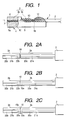
- FIG. 1 shows a basic embodiment of an optical fiber array of the invention.
- Figs. 2A to 2C show various forms for splicing optical fibers having different mode field diameters.
- reference numerals 1 denotes an optical fiber
- 2 denotes a fiber coating portion
- 3 denotes a bare fiber portion
- 3a, 3b denote a bare fiber
- 4 denotes an optical fiber array
- 5 denotes an array substrate
- 5a denotes a fiber aligning portion
- 5b denotes a base portion
- 6 denotes a presser member
- 7 denotes a V-groove
- 10 denotes a spliced portion
- 10a denotes a fat portion
- 11 denotes a first adhesive
- 12 denotes a second adhesive
- 13 denotes a third adhesive
- 20a, 20b denote a cladding portion
- 21a, 21b denote a core portion
- 22a, 22b denote a mode field converting portion.
- the shape of the optical fiber array 4 as shown in Fig. 1 is similar as that of Fig. 6.
- the optical fiber array 4 includes the array substrate 5 and the presser member 6.
- the array substrate 5 includes a fiber aligning portion 5a at a front portion thereof and a base portion 5b with a flat upper face a rear portion thereof.
- the fiber aligning portion 5a has the V-groove 7 for positioning the bare fiber portion 3 in which a fiber coating is removed.
- the bare fiber portion 3 on the array substrate 5 has the bare fiber 3a in which the fiber coating is removed, and the bare fiber 3b that is of different kind from the bare fiber 3a, as shown in Figs. 2A-2C.
- the bare fiber 3b is spliced to a top end of the bare fiber 3a.
- the bare fiber 3a is a standard single mode optical fiber, for example, and has the cladding portion 20a and the core portion 21a.
- the mode field diameter of the core portion 21a is as large as about 10 ⁇ m.
- the bare fiber 3b is a non-standard optical fiber with a dopant added in the core portion 21b at high density, for example, and has the cladding portion 20b around the core portion 21b.
- the mode field diameter of the core portion 21b is as large as about 5 ⁇ m.
- the spliced portion 10 between the bare fiber 3a and the bare fiber 3b is formed by physically abutting the bare fiber 3a against the bare fiber 3b, or formed by fusing the bare fibers 3a and 3b.
- the spliced portion 10 is subjected to the TEC process by additional heating.
- dopants in the core portion 21a, 21b of the bare fiber 3a, 3b is thermally diffused to the cladding portion 20a, 20b to form the mode field converting portion 22a, 22b, thereby making both the mode field diameters coincident or approximate.
- Fig. 2A shows the case where the bare fiber 3a and the bare fiber 3b are abutted and jointed each other.
- an intermediate part of the bare fiber 3b is subjected to the TEC process in advance, and then, a central part of the TEC portion is cleaved and/or polished, thereby matching a spliced end of the bare fiber 3b with the mode field diameter of the bare fiber 3a.
- Figs. 2B and 2C show the case where the bare fiber 3a and the bare fiber 3b are fusion spliced, and the spliced portion 10 is subjected to the TEC process by additional heating after being fusion spliced.
- This TEC process is disclosed in the patent No.2618500.
- fusion splicing there is a case where the outer diameter of the spliced portion 10 has no fat portion of the bare fiber outer diameter, as shown in Fig. 2B.
- the outer diameter of the spliced portion 10 has the fat portion 10a of the bare fiber outer diameter, as shown in Fig. 2C.
- the bare fiber portion 3 of the optical fiber 1 has the bare fiber 3a and the bare fiber 3b, in which the spliced portion has no fat portion, as shown in Fig. 2A or 2B.
- the bare fiber portion 3 is mounted on the fiber aligning portion 5a so that the spliced portion 10 is placed within the V-groove 7 of the array substrate 5, and pressed and positioned by the presser member 6.
- the spliced portion 10 is bonded within the V-groove 7, reinforced and protected by the adhesive.
- a top end portion of the fiber coating portion 2 is mounted on the base portion 5b of the array substrate 5, and the bare fiber portion between the rear end of the V-groove 7 and the fiber coating portion 2 is suspended on the base portion 5.
- the spliced portion 10 may not be pressed by the presser member 6 within the V-groove.
- the bare fiber portion 3 positioned by the V-groove 7 and the presser member 6 is bonded by the first adhesive 11.
- the top end portion of the fiber coating portion 2 is bonded on the base portion 5b by the second adhesive 12.
- the bare fiber portion 3 between the first and second adhesives is bonded by the third adhesive 13.
- the first adhesive 11 is a relatively hard adhesive resin having a Young's modulus after hardening of 500Mpa or more and a viscosity before hardening of 10Pa.s or less.
- the second adhesive 12 is a relatively hard adhesive resin having a Young's modulus after hardening of 500Mpa or more, like the first adhesive 11, and a viscosity before hardening of more than 10Pa.s.
- the third adhesive 13 is a relatively soft adhesive resin having a Young's modulus of less than 500Mpa, which is softer than the first adhesive 11.
- the first adhesive 11 has a relative small viscosity, whereby the bare fiber portion 3 is likely to be aligned within the V-groove 7, and can be correctly positioned by the presser member 6, which will be connected to PLCs. Because the Young's modulus after hardening is large, the bare fiber portion 3 can be firmly bonded by adhesives.
- the second adhesive 12 flows away if it has too small viscosity when applied on the top end portion of the fiber coating portion 2, and hence has a greater viscosity than the first adhesive 11 to be securely applied over the fiber coating portion 2. Since the Young's modulus rafter hardening is as large as the first adhesive 11, the top end portion of the fiber coating portion 2 can be firmly bonded onto the rear end portion of the array substrate 5.
- the first adhesive 11 and the second adhesive 12 can provide a sufficient bearing force against the tensile load in the longitudinal direction of the optical fiber 1.
- the third adhesive 13 is applied over the bare fiber portion 3 between the first adhesive and the second adhesive to protect and bond this bare fiber portion, but has a Young's modulus that is relatively smaller than those of the first and second adhesives. Accordingly, the thermal shrinkage of the third adhesive 13 is reduced at lower temperatures, causing a smaller distortion in the bare fiber portion 3, and preventing an increase in the transmission loss.
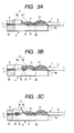
- Figs. 3A to 3C are views showing the examples in which the fat portion 10a as shown in Fig. 2C is present in the spliced portion of the bare fiber 3a and the bare fiber 3b.
- Figs. 3A to 3B the same or like components are designated by the same numerals as in Fig. 1, and are not described.
- the spliced portion 10 is suspended on the base portion 5b outside the V-groove 7, applied with the third adhesive 13, and bonded on the base portion 5b.
- the bare fiber 3b is only mounted in the V-groove 7, positioned, and bonded by the first adhesive 11.
- the spliced portion 10 is protected and reinforced by the third adhesive 13 that is softer.
- the array substrate 5 has a recess portion 7a which is formed in the intermediate part of the V-groove 7.
- the spliced portion 10 is disposed in this recess portion 7a.
- An upper part of the recess portion 7a is not pressed by the presser member 6.
- Both sides of the spliced portion 10 are supported within the V-groove.
- the spliced portion 10 is protected and reinforced by the third adhesive 13.
- the spliced portion 10 is kept more straight between the V-grooves, and bonded by adhesives in more stable state, in contrast to the example of Fig. 3A.
- the array substrate 5 has the recess portion 7a which is formed in the intermediate part of the V-groove 7.
- the presser member 6 has a recess portion 6a which is formed at a position confronting the recess portion 7a on the presser member 6. Therefore, the spliced portion 10 is disposed in a gap between the recess portions 6a and 7a.
- the spliced portion 10 is supported within the gap formed by the recess portions 6a and 7a, and protected and reinforced by the first adhesive 11 applied in the V-groove 7.
- the spliced portion 10 is positioned by the V-groove 7 and the presser member 6 on both sides, and bonded by the first adhesive 11 to have a greater strength against the tensile load, in contrast to the example of Figs. 3A and 3B.
- a rear edge portion of the array substrate 5 may be formed of a tapered or arc-shaped smooth face 5e (indicated by the dotted line), improving a contact state between the optical fiber 1 and a rear edge of the array substrate 5.
- the optical fiber 1 is less subjected to a damage by the rear edge of the array substrate 5, or is less likely to be bent excessively under the optical fiber array 4, reducing a disconnection or an increase in the transmission loss.
- Figs. 4 and 5A-5B are views showing the examples in which the contact of the optical fiber(s) with the rear edge of the array substrate is improved by the use of a protection member.
- Fig. 4 shows an example in which the protection member preformed like a tube is employed.
- Fig. 5A shows an example in which the protection member is formed by molding on the fiber coating portion and the bare fiber portion.
- Fig. 5B shows an example in which the protection member is formed by molding on the fiber coating portion.
- reference numerals 14 and 15 denote the protectionmember.
- Other components are designated by the same reference numerals as used in Fig. 1, and not described.
- spliced portion 10 between the bare fiber 3a and the bare fiber 3b is suspended on the base portion 5b rearward of the V-groove 7 as shown in Fig. 3A, coated with the third adhesive 13, and fixed on the base portion 5b by the adhesive 13.
- the constitution or form as shown in Figs. 1, 3B and 3C is also applied to this embodiment.
- the tube protection member 14 is provided over the fiber coating portion extending over the rear edge 5c of the array substrate 5, thereby preventing the optical fiber 1 from directly coming into contact with the rear edge 5c of the array substrate 5.
- the tube protectionmember 14 is preformed, then the optical fiber 1 is inserted, fixed onto the fiber coating portion 2 by the adhesive, and mounted on the array substrate 5.
- the process may be reversed: after the tube protection member 14 is fixed at the rear end portion of the array substrate 5 by the adhesive, then the optical fiber may be inserted through a tube of the protection member 14.
- the tube protection member 14 is formed of a flexible, bendable material such as rubber, silicone or polymer like Nylon.
- the protection member 14 is attached with a slight distance (e.g., about 0.5mm to 2.0mm) from the top end of the fiber coating portion 2, so that the fiber coating portion 2, which is not covered by the protection member 14, may adhere to the array substrate 5.
- the protection member 14 has a length with a certain amount of extension (e.g., desirably about 3mm to 5mm) from the rear end of the array substrate 5.
- the protection member 14 is positioned for attachment by abutting its top end against a shoulder of a step portion 5d provided on the base portion 5b of the array substrate 5.
- the protection member 14 is bonded integrally with the optical fiber 1 by applying the adhesive to fill in a part or the entire gap portion between the protection member 14 and the fiber coating portion 2. This adhesive may or may not be the same as the second adhesive.
- the protection member 14 may be attached individually on each optical fiber integrally or all optical fibers, or attached on the optical fiber ribbon.
- the bare fiber portion 3 positioned by the V-groove 7 is fixed by the first adhesive 11.
- the top end portion of the fiber coating portion 2 is fixed on the base portion 5b by the second adhesive 12.
- the bare fiber portion 3 between the first and second adhesives is fixed by the third adhesive 13.
- the first adhesive 11 is a relatively hard adhesive resin having a Young's modulus after hardening of greater than 500Mpa and a viscosity before hardening of 10Pa.s or less.
- the second adhesive 12 is a relatively hard adhesive resin having a Young's modulus after hardening of greater than 500Mpa, like the first adhesive 11, and a viscosity before hardening of 10Pa.s or more that is greater than that of the first adhesive 11.
- the third adhesive 13 is a relatively soft adhesive resin having a Young's modulus of less than 500Mpa, which is softer than the first adhesive 11.
- the second adhesive 12 for bonding the fiber coating portion 2 on the array substrate 5 is applied to cover a part of the fiber coating portion 2 projecting from the top end of the protection member 14 and a part of the protection member 14 mounted on the array substrate 5. Thereby, the tensile load in the longitudinal direction of the optical fiber 1 is prevented from being directly applied on the bare fiber portion 3 bonded in the V-groove 7, as in the case of Fig. 1.
- the protection member 14 is located to extend over the rear edge 5c of the array substrate 5, and serves as a cushion for preventing the optical fiber array 1 from directly coming into contact therewith. Also, the optical fiber 1 is less subjected to a damage by the rear edge of the array substrate 5, or is less likely to be bent excessively under the optical fiber array 4, reducing the possibility of the disconnection or an increase in the transmission loss, without working the rear edge of the array substrate 5 with a smooth face, as shown in Figs. 3A-3C.
- the protection member 15 is formed, using a mold, to cover an end portion of the fiber coating portion 2 for the optical fiber 1 and a part of the bare fiber portion 3.
- the protection member 15 is provided to extend over the rear edge 5c of the array substrate 5 to prevent the optical fiber 1 from directly coming into contact with the rear edge 5c of the array substrate 5.
- the protection member 15 is formed, using a mold, to cover an outer circumference of an end portion of the fiber coating portion 2 for the optical fiber 1 so that the top end of the fiber coating portion projects by a slight amount (e.g., about 0.5mm to 2mm) from the protection member 15.
- the protection member 15 is provided to extend over the rear edge 5c of the array substrate 5 to prevent the optical fiber 1 from directly coming into contact with the rear edge 5c of the array substrate 5.
- the protection member 15 is formed of a flexible, bendable material such as rubber, silicon or Nylon.
- the protection member 15 desirably has an excellent adhesion with the fiber coating portion 2, and a large rupture elongation.
- the protection member 15 is formed to have a certain amount of extension (e.g., desirably about 3mm to 5mm) from the rear end of the array substrate 5.
- This projecting portion 15a is preferably tapered to prevent the stress against the bending from applying the optical fiber.
- the protection member 15 is positioned for attachment by abutting its top end against a shoulder of the step portion 5d provided on the base portion 5b of the array substrate 5.
- the bare fiber portion 3 positioned by the V-groove 7 is bonded by the first adhesive 11.
- the top end portion of the fiber coating portion 2 is bonded on the base portion 5b by the second adhesive 12.
- the bare fiber portion 3 between the first and second adhesives is bonded by the third adhesive 13.
- the first adhesive 11 is a relatively hard adhesive resin having a Young's modulus after hardening of greater than 500Mpa and a viscosity before hardening of 10Pa.s or less.
- the second adhesive 12 is a relatively hard adhesive resin having a Young's modulus after hardening of greater than 500Mpa, like the first adhesive 11, and a viscosity before hardening of 10Pa.s or more that is greater than that of the first adhesive 11.
- the third adhesive 13 is a relatively soft adhesive resin having a Young's modulus of less than 500Mpa, which is softer than the first adhesive 11.
- the second adhesive 12 for bonding the fiber coating portion 2 on the array substrate 5 is applied to cover the protection member 15 mounted on the array substrate 5 in Fig. 5A. Also, the second adhesive 12 is applied to cover a part of the fiber coating portion 2 exposed and projecting from the top end of the protection member 15 and a part of the protection member 15 mounted on the array substrate 5 in Fig. 5B. Thereby, the tensile load in the longitudinal direction of the optical fiber 1 is prevented from being directly applied on the bare fiber portion 3 bonded in the V-groove 7, as in the case of Fig. 1.
- the protection member 15 is located to extend over the rear edge 5c of the array substrate 5, and serves as a cushion for preventing the optical fiber array 1 from directly coming into contact therewith. Also, the optical fiber 1 is less subjected to a damage by the rear edge of the array substrate 5, or is less likely to be bent excessively under the optical fiber array 4, reducing the disconnection or an increase in the transmission loss, without working the rear edge of the array substrate 5 with a smooth face, as shown in Figs. 3A-3C. However, even when the protection member 14 or 15 is employed, the rear edge of the array substrate 5 may be formed with a smooth face that is tapered or arc-shaped, as in the case of Figs. 3A-3C. Through Fig. 1 to Fig. 5A, an optical fiber is drawn, however, the present invention is not limited to an optical fiber. Namely, optical fibers may be fixed onto a substrate to form an optical fiber array in this invention.
- the spliced portion of the dissimilar optical fibers having different mode field diameters can be contained within the optical fiber array. Therefore, the optical fiber is easily led in a small space within the optical communication unit, thereby making it possible to miniaturize the unit. Also, the protection member is provided to prevent the optical fiber from being in contact with the rear edge of the optical fiber array, whereby the disconnection or an increase in the transmission loss canbe reduced.
- the optical fiber is bonded onto the optical fiber array, employing three kinds of adhesives that are different in the Young's modulus after hardening, or the viscosity before hardening, whereby the optical fiber can be strong enough to resist the tensile load, and can prevent an increase in the transmission loss due to a temperature change.
Abstract
Description
Claims (14)
- An optical fiber array comprising:wherein the spliced portion of the dissimilar optical fibers is disposed on the array substrate.an optical fiber formed by splicing dissimilar optical fibers having different mode field diameters, the optical fiber having a fiber coating portion in which a fiber coating is applied and a bare fiber portion in which the fiber coating is removed, the bare fiber portion having a spliced portion of the dissimilar optical fibers in the middle;an array substrate for mounting the optical fiber thereon, the array substrate having a fiber aligning portion and a base portion, the fiber aligning portion having a V-groove for positioning the bare fiber portion of the optical fiber;a pressure member for pressing the bare fiber portion to the V-groove of the array substrate; anda first adhesive for fixing the bare fiber portion to the V-groove of the array substrate,
- The optical fiber array according to claim 1, wherein the dissimilar optical fibers are fusion spliced at the spliced portion.
- The optical fiber array according to claim 2, wherein the bare fiber portion has a mode field conversion portion formed by heating the spliced portion of the dissimilar optical fibers.
- The optical fiber array according to claim 1, wherein the spliced portion is disposed on the base portion of the array substrate.
- The optical fiber array according to claim 1, wherein the spliced portion is disposed in the V-groove.
- The optical fiber array according to claim 5, wherein the V-groove has a recess portion, and wherein the spliced portion is disposed in the recess portion of the V-groove.
- The optical fiber array according to claim 1, wherein the array substrate has a tapered or arc-shaped rear end portion.
- The optical fiber array according to claim 1, further comprising:a protection member for protecting the optical fiber extending over a rear edge of the array substrate.
- The optical fiber array according to claim 8, wherein the protection member has a tube shape for accommodating the optical fiber therein.
- The optical fiber array according to claim 8, wherein the protection member is formed by a mold.
- The optical fiber array according to claim 8, wherein a portion of the protection member extending over the array substrate has a tapered shape.
- The optical fiber array according to claim 8, wherein the protection member covers the fiber coating portion.
- The optical fiber array according to claim 8, wherein the array substrate has a step portion for mounting the protection member thereon.
- The optical fiber array according to claim 1, further comprising:wherein the first adhesive has a Young's modulus after hardening of 500Mpa or more and a viscosity before hardening of 10Pa.s or less, the second adhesive has a greater viscosity before hardening than the first adhesive, and the third adhesive has a smaller Young's modulus after hardening than the first adhesive.a second adhesive for fixing the fiber coating portion of the optical fiber on the base portion of the array substrate; anda third adhesive for covering and fixing the bare fiber portion which is not disposed in the V-groove,
Applications Claiming Priority (2)
| Application Number | Priority Date | Filing Date | Title |
|---|---|---|---|
| JP2002036753 | 2002-02-14 | ||
| JP2002036753A JP3748065B2 (en) | 2002-02-14 | 2002-02-14 | Optical fiber array |
Publications (3)
| Publication Number | Publication Date |
|---|---|
| EP1336882A2 true EP1336882A2 (en) | 2003-08-20 |
| EP1336882A3 EP1336882A3 (en) | 2004-11-17 |
| EP1336882B1 EP1336882B1 (en) | 2006-06-21 |
Family
ID=27621420
Family Applications (1)
| Application Number | Title | Priority Date | Filing Date |
|---|---|---|---|
| EP02017769A Expired - Lifetime EP1336882B1 (en) | 2002-02-14 | 2002-08-09 | Optical fiber array |
Country Status (6)
| Country | Link |
|---|---|
| US (1) | US7021842B2 (en) |
| EP (1) | EP1336882B1 (en) |
| JP (1) | JP3748065B2 (en) |
| CN (1) | CN1246713C (en) |
| CA (1) | CA2394258C (en) |
| DE (1) | DE60212562D1 (en) |
Cited By (3)
| Publication number | Priority date | Publication date | Assignee | Title |
|---|---|---|---|---|
| EP2423722A1 (en) * | 2010-08-25 | 2012-02-29 | CCS Technology, Inc. | Fiber optic adapter with permanently fixed fiber optic ferrule on the first side thereof |
| WO2013126429A2 (en) | 2012-02-20 | 2013-08-29 | Adc Telecommunications, Inc. | Fiber optic connector, fiber optic connector and cable assembly, and methods for manufacturing |
| US10649161B2 (en) | 2012-04-11 | 2020-05-12 | Cudoquanta Florida, Inc. | Hermetic optical fiber alignment assembly |
Families Citing this family (18)
| Publication number | Priority date | Publication date | Assignee | Title |
|---|---|---|---|---|
| WO2005006047A1 (en) * | 2003-07-10 | 2005-01-20 | Ngk Insulators, Ltd. | Optical device and method for producing same |
| US7828773B2 (en) | 2005-07-11 | 2010-11-09 | Covidien Ag | Safety reset key and needle assembly |
| US7556440B2 (en) * | 2006-12-22 | 2009-07-07 | Lightwire Inc. | Dual-lensed unitary optical receiver assembly |
| JP4879924B2 (en) * | 2008-02-15 | 2012-02-22 | Nttエレクトロニクス株式会社 | Optical component and optical fiber holding method |
| CN102854570B (en) * | 2011-06-28 | 2015-07-01 | 鸿富锦精密工业(深圳)有限公司 | Optical fiber coupling connector |
| US9946033B2 (en) * | 2013-08-07 | 2018-04-17 | Corning Optical Communications LLC | Fiber optic connector with adhesive management |
| JP2015075632A (en) * | 2013-10-09 | 2015-04-20 | 三菱電機株式会社 | Light source device |
| JP6491418B2 (en) * | 2014-03-14 | 2019-03-27 | 日立金属株式会社 | Fiber optic connector |
| JP5905563B1 (en) * | 2014-12-01 | 2016-04-20 | 株式会社フジクラ | Manufacturing method of semiconductor laser module |
| CN108139547B (en) * | 2015-10-12 | 2020-09-08 | 3M创新有限公司 | Optical waveguide positioning features in a multi-waveguide connector |
| JP2017120282A (en) * | 2015-12-28 | 2017-07-06 | 株式会社フジクラ | Fusion-spliced part reinforcing structure and method of manufacturing fusion-spliced part reinforcing structure |
| CN106291823A (en) * | 2016-09-27 | 2017-01-04 | 北京浦丹光电股份有限公司 | A kind of pigtail assembly structure and manufacture method |
| JP2018146722A (en) * | 2017-03-03 | 2018-09-20 | 株式会社フジクラ | Optical fiber array |
| JP7266789B2 (en) * | 2018-02-20 | 2023-05-01 | 住友電気工業株式会社 | Optical fiber manufacturing method and optical fiber |
| JP2019197131A (en) * | 2018-05-09 | 2019-11-14 | 株式会社フジクラ | Optical fiber array, substrate for fixing fiber and method for manufacturing optical fiber array |
| JP2020038304A (en) * | 2018-09-04 | 2020-03-12 | 住友電気工業株式会社 | Optical connection device, and method for manufacturing the optical connection device |
| US11086075B2 (en) | 2019-10-30 | 2021-08-10 | Alliance Fiber Optic Products, Inc. | Fiber array units with mode-field diameter conversion, and fabrication method |
| JP2022135003A (en) * | 2021-03-04 | 2022-09-15 | 住友電気工業株式会社 | optical connector cable |
Citations (7)
| Publication number | Priority date | Publication date | Assignee | Title |
|---|---|---|---|---|
| JPH04130304A (en) * | 1990-09-21 | 1992-05-01 | Sumitomo Electric Ind Ltd | Optical connector |
| EP0624808A1 (en) * | 1993-03-29 | 1994-11-17 | Sumitomo Electric Industries, Ltd. | Optical connector |
| US5764833A (en) * | 1993-03-31 | 1998-06-09 | Sumitomo Electric Industries, Ltd. | Optical fiber array |
| EP0859253A1 (en) * | 1996-08-01 | 1998-08-19 | Furukawa Denki Kogyo Kabushiki Kaisha | Multicore optical connector and method of producing the connector |
| JPH1184164A (en) * | 1997-09-09 | 1999-03-26 | Hitachi Cable Ltd | Optical fiber array and its production |
| EP0943941A1 (en) * | 1998-03-19 | 1999-09-22 | Ngk Insulators, Ltd. | Optical fiber array and production method thereof |
| JP2002040290A (en) * | 2000-07-28 | 2002-02-06 | Nippon Telegr & Teleph Corp <Ntt> | Fiber array part and its manufacturing method |
Family Cites Families (12)
| Publication number | Priority date | Publication date | Assignee | Title |
|---|---|---|---|---|
| DE3617799A1 (en) * | 1986-05-27 | 1987-12-03 | Standard Elektrik Lorenz Ag | Optical transmitter |
| US4900118A (en) * | 1987-05-22 | 1990-02-13 | Furukawa Electric Co., Ltd. | Multiple-fiber optical component and method for manufacturing of the same |
| JP2618500B2 (en) * | 1989-10-17 | 1997-06-11 | 日本電信電話株式会社 | Optical fiber connection method |
| JPH0664213U (en) * | 1993-02-17 | 1994-09-09 | 日本電信電話株式会社 | Optical connector ferrule |
| JPH0735958A (en) * | 1993-07-23 | 1995-02-07 | Sumitomo Electric Ind Ltd | Parallel transmission module |
| JPH08110441A (en) * | 1994-10-07 | 1996-04-30 | Hitachi Cable Ltd | Optical fiber array |
| US6345916B1 (en) * | 1998-11-25 | 2002-02-12 | Sumitomo Electric Industries, Ltd. | Fiber optic connector and its manufacturing method |
| JP2000241664A (en) * | 1999-02-23 | 2000-09-08 | Sumitomo Electric Ind Ltd | Optical fiber holding tool |
| JP2000275470A (en) | 1999-03-19 | 2000-10-06 | Nippon Telegr & Teleph Corp <Ntt> | Planar optical wave circuit device with input/output fiber |
| JP2000066062A (en) * | 1999-09-13 | 2000-03-03 | Sumitomo Electric Ind Ltd | Parallel transmission module |
| JP2003156662A (en) * | 2001-11-21 | 2003-05-30 | Ngk Insulators Ltd | Optical fiber array and method for manufacturing the same |
| JP3613244B2 (en) * | 2002-01-18 | 2005-01-26 | 住友電気工業株式会社 | Optical fiber array |
-
2002
- 2002-02-14 JP JP2002036753A patent/JP3748065B2/en not_active Expired - Fee Related
- 2002-07-19 CA CA002394258A patent/CA2394258C/en not_active Expired - Fee Related
- 2002-08-08 CN CN02127749.4A patent/CN1246713C/en not_active Expired - Fee Related
- 2002-08-09 EP EP02017769A patent/EP1336882B1/en not_active Expired - Lifetime
- 2002-08-09 DE DE60212562T patent/DE60212562D1/en not_active Expired - Lifetime
- 2002-08-19 US US10/222,795 patent/US7021842B2/en not_active Expired - Fee Related
Patent Citations (7)
| Publication number | Priority date | Publication date | Assignee | Title |
|---|---|---|---|---|
| JPH04130304A (en) * | 1990-09-21 | 1992-05-01 | Sumitomo Electric Ind Ltd | Optical connector |
| EP0624808A1 (en) * | 1993-03-29 | 1994-11-17 | Sumitomo Electric Industries, Ltd. | Optical connector |
| US5764833A (en) * | 1993-03-31 | 1998-06-09 | Sumitomo Electric Industries, Ltd. | Optical fiber array |
| EP0859253A1 (en) * | 1996-08-01 | 1998-08-19 | Furukawa Denki Kogyo Kabushiki Kaisha | Multicore optical connector and method of producing the connector |
| JPH1184164A (en) * | 1997-09-09 | 1999-03-26 | Hitachi Cable Ltd | Optical fiber array and its production |
| EP0943941A1 (en) * | 1998-03-19 | 1999-09-22 | Ngk Insulators, Ltd. | Optical fiber array and production method thereof |
| JP2002040290A (en) * | 2000-07-28 | 2002-02-06 | Nippon Telegr & Teleph Corp <Ntt> | Fiber array part and its manufacturing method |
Non-Patent Citations (4)
| Title |
|---|
| PATENT ABSTRACTS OF JAPAN vol. 016, no. 396 (P-1407), 21 August 1992 (1992-08-21) & JP 04 130304 A (SUMITOMO ELECTRIC IND LTD), 1 May 1992 (1992-05-01) * |
| PATENT ABSTRACTS OF JAPAN vol. 1996, no. 08, 30 August 1996 (1996-08-30) -& JP 08 110441 A (HITACHI CABLE LTD), 30 April 1996 (1996-04-30) -& DATABASE WPI Section PQ, Week 199627 Derwent Publications Ltd., London, GB; Class P81, AN 1996-264920 XP002296922 & JP 08 110441 A (HITACHI CABLE LTD), 30 April 1996 (1996-04-30) * |
| PATENT ABSTRACTS OF JAPAN vol. 1999, no. 08, 30 June 1999 (1999-06-30) -& JP 11 084164 A (HITACHI CABLE LTD), 26 March 1999 (1999-03-26) * |
| PATENT ABSTRACTS OF JAPAN vol. 2002, no. 06, 4 June 2002 (2002-06-04) -& JP 2002 040290 A (NIPPON TELEGR & TELEPH CORP <NTT>), 6 February 2002 (2002-02-06) * |
Cited By (8)
| Publication number | Priority date | Publication date | Assignee | Title |
|---|---|---|---|---|
| EP2423722A1 (en) * | 2010-08-25 | 2012-02-29 | CCS Technology, Inc. | Fiber optic adapter with permanently fixed fiber optic ferrule on the first side thereof |
| WO2012027315A1 (en) * | 2010-08-25 | 2012-03-01 | Ccs Technology, Inc. | Fiber optic adapter |
| WO2013126429A2 (en) | 2012-02-20 | 2013-08-29 | Adc Telecommunications, Inc. | Fiber optic connector, fiber optic connector and cable assembly, and methods for manufacturing |
| EP2817668A4 (en) * | 2012-02-20 | 2015-09-30 | Adc Telecommunications Inc | Fiber optic connector, fiber optic connector and cable assembly, and methods for manufacturing |
| US9470850B2 (en) | 2012-02-20 | 2016-10-18 | Commscope Technologies Llc | Fiber optic connector, fiber optic connector and cable assembly, and methods for manufacturing |
| US10353154B2 (en) | 2012-02-20 | 2019-07-16 | Commscope Technologies Llc | Fiber optic connector, fiber optic connector and cable assembly, and methods for manufacturing |
| US11125951B2 (en) | 2012-02-20 | 2021-09-21 | Commscope Technologies Llc | Fiber optic connector, fiber optic connector and cable assembly, and methods for manufacturing |
| US10649161B2 (en) | 2012-04-11 | 2020-05-12 | Cudoquanta Florida, Inc. | Hermetic optical fiber alignment assembly |
Also Published As
| Publication number | Publication date |
|---|---|
| US20030152343A1 (en) | 2003-08-14 |
| US7021842B2 (en) | 2006-04-04 |
| CN1246713C (en) | 2006-03-22 |
| EP1336882B1 (en) | 2006-06-21 |
| CN1438773A (en) | 2003-08-27 |
| CA2394258C (en) | 2006-11-21 |
| JP2003241020A (en) | 2003-08-27 |
| EP1336882A3 (en) | 2004-11-17 |
| DE60212562D1 (en) | 2006-08-03 |
| CA2394258A1 (en) | 2003-08-14 |
| JP3748065B2 (en) | 2006-02-22 |
Similar Documents
| Publication | Publication Date | Title |
|---|---|---|
| EP1336882B1 (en) | Optical fiber array | |
| KR100225026B1 (en) | Optical fiber array | |
| CN101939681B (en) | Remote grip optical fiber connector | |
| JP3259742B2 (en) | Optical waveguide module | |
| EP0191064A1 (en) | Optical fiber connector and articles connected therewith. | |
| CA2569263A1 (en) | Optical ferrule | |
| JPH10170756A (en) | Optical connector and its fitting method | |
| US5892871A (en) | Fiber optic cable termination | |
| CN108139547A (en) | Optical waveguide locating feature in more waveguide connectors | |
| US6767136B1 (en) | Device having multiple optical fibers | |
| JPH09145959A (en) | Multiple-core optical connector for ribon-type optical cable | |
| JPH11242127A (en) | Optical fiber array | |
| US20100002984A1 (en) | Optical waveguide device | |
| JP2000338371A (en) | Optical fiber connector | |
| WO1999005553A1 (en) | Optical fiber retention and strain relief collar | |
| JP2003215392A (en) | Optical fiber array | |
| JP3410672B2 (en) | Optical connector and method of manufacturing the same | |
| JP3301197B2 (en) | Parallel transmission module and manufacturing method thereof | |
| JP3485465B2 (en) | Optical connector | |
| JPH0373842B2 (en) | ||
| JP3700775B2 (en) | Optical fiber array | |
| JPH11337761A (en) | Optical fiber connector | |
| JP2004317927A (en) | V-groove pedestal setting for coated optical fiber connection and method for assembling coated optical fiber connection tool using same | |
| JPH11258459A (en) | Optical fiber connector | |
| TW200424582A (en) | Optical connector using an optical fiber having a special fiber portion as a part thereof |
Legal Events
| Date | Code | Title | Description |
|---|---|---|---|
| PUAI | Public reference made under article 153(3) epc to a published international application that has entered the european phase |
Free format text: ORIGINAL CODE: 0009012 |
|
| 17P | Request for examination filed |
Effective date: 20020809 |
|
| AK | Designated contracting states |
Designated state(s): AT BE BG CH CY CZ DE DK EE ES FI FR GB GR IE IT LI LU MC NL PT SE SK TR |
|
| AX | Request for extension of the european patent |
Extension state: AL LT LV MK RO SI |
|
| PUAL | Search report despatched |
Free format text: ORIGINAL CODE: 0009013 |
|
| AK | Designated contracting states |
Kind code of ref document: A3 Designated state(s): AT BE BG CH CY CZ DE DK EE ES FI FR GB GR IE IT LI LU MC NL PT SE SK TR |
|
| AX | Request for extension of the european patent |
Extension state: AL LT LV MK RO SI |
|
| 17Q | First examination report despatched |
Effective date: 20050530 |
|
| AKX | Designation fees paid |
Designated state(s): DE FR GB IT |
|
| GRAP | Despatch of communication of intention to grant a patent |
Free format text: ORIGINAL CODE: EPIDOSNIGR1 |
|
| GRAS | Grant fee paid |
Free format text: ORIGINAL CODE: EPIDOSNIGR3 |
|
| GRAA | (expected) grant |
Free format text: ORIGINAL CODE: 0009210 |
|
| AK | Designated contracting states |
Kind code of ref document: B1 Designated state(s): DE FR GB IT |
|
| PG25 | Lapsed in a contracting state [announced via postgrant information from national office to epo] |
Ref country code: IT Free format text: LAPSE BECAUSE OF FAILURE TO SUBMIT A TRANSLATION OF THE DESCRIPTION OR TO PAY THE FEE WITHIN THE PRESCRIBED TIME-LIMIT;WARNING: LAPSES OF ITALIAN PATENTS WITH EFFECTIVE DATE BEFORE 2007 MAY HAVE OCCURRED AT ANY TIME BEFORE 2007. THE CORRECT EFFECTIVE DATE MAY BE DIFFERENT FROM THE ONE RECORDED. Effective date: 20060621 |
|
| REG | Reference to a national code |
Ref country code: GB Ref legal event code: FG4D |
|
| REF | Corresponds to: |
Ref document number: 60212562 Country of ref document: DE Date of ref document: 20060803 Kind code of ref document: P |
|
| PG25 | Lapsed in a contracting state [announced via postgrant information from national office to epo] |
Ref country code: DE Free format text: LAPSE BECAUSE OF FAILURE TO SUBMIT A TRANSLATION OF THE DESCRIPTION OR TO PAY THE FEE WITHIN THE PRESCRIBED TIME-LIMIT Effective date: 20060922 |
|
| ET | Fr: translation filed | ||
| PLBE | No opposition filed within time limit |
Free format text: ORIGINAL CODE: 0009261 |
|
| STAA | Information on the status of an ep patent application or granted ep patent |
Free format text: STATUS: NO OPPOSITION FILED WITHIN TIME LIMIT |
|
| 26N | No opposition filed |
Effective date: 20070322 |
|
| PGFP | Annual fee paid to national office [announced via postgrant information from national office to epo] |
Ref country code: FR Payment date: 20140808 Year of fee payment: 13 Ref country code: GB Payment date: 20140806 Year of fee payment: 13 |
|
| GBPC | Gb: european patent ceased through non-payment of renewal fee |
Effective date: 20150809 |
|
| REG | Reference to a national code |
Ref country code: FR Ref legal event code: ST Effective date: 20160429 |
|
| PG25 | Lapsed in a contracting state [announced via postgrant information from national office to epo] |
Ref country code: GB Free format text: LAPSE BECAUSE OF NON-PAYMENT OF DUE FEES Effective date: 20150809 |
|
| PG25 | Lapsed in a contracting state [announced via postgrant information from national office to epo] |
Ref country code: FR Free format text: LAPSE BECAUSE OF NON-PAYMENT OF DUE FEES Effective date: 20150831 |