EP1341359B1 - System and method for determining the source of an internet protocol packet - Google Patents
System and method for determining the source of an internet protocol packet Download PDFInfo
- Publication number
- EP1341359B1 EP1341359B1 EP03003010.0A EP03003010A EP1341359B1 EP 1341359 B1 EP1341359 B1 EP 1341359B1 EP 03003010 A EP03003010 A EP 03003010A EP 1341359 B1 EP1341359 B1 EP 1341359B1
- Authority
- EP
- European Patent Office
- Prior art keywords
- cell
- source
- packet
- address
- destination
- Prior art date
- Legal status (The legal status is an assumption and is not a legal conclusion. Google has not performed a legal analysis and makes no representation as to the accuracy of the status listed.)
- Expired - Lifetime
Links
- 238000000034 method Methods 0.000 title claims description 19
- 238000013519 translation Methods 0.000 claims description 28
- 230000015654 memory Effects 0.000 claims description 12
- 230000014616 translation Effects 0.000 description 17
- 238000004891 communication Methods 0.000 description 15
- 238000010586 diagram Methods 0.000 description 9
- 230000005540 biological transmission Effects 0.000 description 7
- 230000003287 optical effect Effects 0.000 description 4
- 230000008569 process Effects 0.000 description 4
- 238000012545 processing Methods 0.000 description 4
- 238000003491 array Methods 0.000 description 3
- 238000005259 measurement Methods 0.000 description 3
- 238000011330 nucleic acid test Methods 0.000 description 3
- 238000011144 upstream manufacturing Methods 0.000 description 3
- 238000012937 correction Methods 0.000 description 2
- 238000001514 detection method Methods 0.000 description 2
- 230000000694 effects Effects 0.000 description 2
- 230000000977 initiatory effect Effects 0.000 description 2
- 238000012986 modification Methods 0.000 description 2
- 230000004048 modification Effects 0.000 description 2
- 238000009739 binding Methods 0.000 description 1
- 230000027455 binding Effects 0.000 description 1
- 230000008859 change Effects 0.000 description 1
- 239000003795 chemical substances by application Substances 0.000 description 1
- 230000006837 decompression Effects 0.000 description 1
- 230000007423 decrease Effects 0.000 description 1
- 238000011161 development Methods 0.000 description 1
- 230000018109 developmental process Effects 0.000 description 1
- 238000000605 extraction Methods 0.000 description 1
- 230000006870 function Effects 0.000 description 1
- 238000009499 grossing Methods 0.000 description 1
- 238000007689 inspection Methods 0.000 description 1
- 238000013507 mapping Methods 0.000 description 1
- 230000007246 mechanism Effects 0.000 description 1
- 239000013307 optical fiber Substances 0.000 description 1
- 230000000737 periodic effect Effects 0.000 description 1
- 230000004044 response Effects 0.000 description 1
- 239000004065 semiconductor Substances 0.000 description 1
- 230000011664 signaling Effects 0.000 description 1
- 238000012360 testing method Methods 0.000 description 1
Images


Classifications
-
- H—ELECTRICITY
- H04—ELECTRIC COMMUNICATION TECHNIQUE
- H04L—TRANSMISSION OF DIGITAL INFORMATION, e.g. TELEGRAPHIC COMMUNICATION
- H04L61/00—Network arrangements, protocols or services for addressing or naming
- H04L61/09—Mapping addresses
- H04L61/25—Mapping addresses of the same type
- H04L61/2503—Translation of Internet protocol [IP] addresses
- H04L61/255—Maintenance or indexing of mapping tables
-
- H—ELECTRICITY
- H04—ELECTRIC COMMUNICATION TECHNIQUE
- H04L—TRANSMISSION OF DIGITAL INFORMATION, e.g. TELEGRAPHIC COMMUNICATION
- H04L45/00—Routing or path finding of packets in data switching networks
-
- H—ELECTRICITY
- H04—ELECTRIC COMMUNICATION TECHNIQUE
- H04L—TRANSMISSION OF DIGITAL INFORMATION, e.g. TELEGRAPHIC COMMUNICATION
- H04L61/00—Network arrangements, protocols or services for addressing or naming
-
- H—ELECTRICITY
- H04—ELECTRIC COMMUNICATION TECHNIQUE
- H04L—TRANSMISSION OF DIGITAL INFORMATION, e.g. TELEGRAPHIC COMMUNICATION
- H04L65/00—Network arrangements, protocols or services for supporting real-time applications in data packet communication
- H04L65/1066—Session management
- H04L65/1101—Session protocols
- H04L65/1104—Session initiation protocol [SIP]
-
- H—ELECTRICITY
- H04—ELECTRIC COMMUNICATION TECHNIQUE
- H04L—TRANSMISSION OF DIGITAL INFORMATION, e.g. TELEGRAPHIC COMMUNICATION
- H04L65/00—Network arrangements, protocols or services for supporting real-time applications in data packet communication
- H04L65/80—Responding to QoS
-
- H—ELECTRICITY
- H04—ELECTRIC COMMUNICATION TECHNIQUE
- H04L—TRANSMISSION OF DIGITAL INFORMATION, e.g. TELEGRAPHIC COMMUNICATION
- H04L61/00—Network arrangements, protocols or services for addressing or naming
- H04L61/09—Mapping addresses
- H04L61/25—Mapping addresses of the same type
- H04L61/2503—Translation of Internet protocol [IP] addresses
- H04L61/2557—Translation policies or rules
Definitions
- the present invention generally relates to telecommunications and, more particularly, is related to a system and method for determining a source of a received Internet protocol packet.
- PSTN public switched telephone network
- IP Internet protocol
- IPv4 Internet protocol version 4
- Each IP address also has a certain number of bits dedicated to a network portion and a certain number of bits dedicated to a host portion.
- multimedia utilized herein is intended to comprise one or more of the following: voice, data, text, graphics, animation, and/or discrete media.
- multimedia packets comprise a header portion and an IP packet data portion.
- the header portion of the multimedia packet at a minimum, comprises at least a source portion and a destination portion, wherein the source portion identifies a source address from which the packet originated, and the destination portion identifies a destination address to which the packet is addressed.
- additional portions of the header portion may be provided, in addition to the source portion and the destination portion such as, but not limited to, a real-time packet header or a real-time control packet header.
- the IP packet data portion of the multimedia packet comprises the remaining portion of the multimedia packet, which comprises data that is being transmitted to a destination device located at the destination address.
- the multimedia packet As the multimedia packet is received by different devices on a path taken by the multimedia packet to the destination device, it is common for the source and/or destination portions of the multimedia packet to change properties, thereby reflecting a most recent source and destination.
- the acceptance or denial of multimedia packets based upon the original source is a characteristic of devices such as, but not limited to, firewalls.
- devices such as, but not limited to, firewalls.
- the original source of the multimedia packet is not known. Since the original source is not known, the destination device is incapable of accurately declining receipt of multimedia packets from a predefined source.
- WO 01/97449 discloses a communication packet processor with a look-up engine to retrieve context information for a core processor.
- WO 00/33204 discloses a system and method for providing desired service policies to subscribers accessing internet.
- the source determination system of the present invention can be implemented in software, firmware, hardware, or a combination thereof.
- a portion of the system is implemented in software that is executed by a network processor.
- the software based portion of the source determination system which comprises an ordered listing of executable instructions for implementing logical functions, can be embodied in any computer-readable medium for use by, or in connection with, an instruction execution system, apparatus, or device such as a computer-based system processor containing system, or other system that can fetch the instructions from the instruction execution system, apparatus, or device and execute the instructions.
- a "computer-readable medium” can be any means that can contain, store, communicate, propagate or transport the program for use by or in connection with the instruction execution system, apparatus or device.
- the computer-readable medium can be, for example, but not limited to, an electronic, magnetic, optical, electromagnetic, infrared, or semiconductor system, apparatus, device, or propagation medium. More specific examples (a non-exhaustive list) of the computer-readable medium would include the following: an electrical connection (electronic) having one or more wires, a portable computer diskette (magnetic), a random access memory (RAM) (magnetic), a read-only memory (ROM) (magnetic), an erasable programmable read-only memory (EPROM or Flash memory) (magnetic), an optical fiber (optical), and a portable compact disk read-only memory (CD ROM) (optical).
- an electrical connection electronic having one or more wires
- a portable computer diskette magnetic
- RAM random access memory
- ROM read-only memory
- EPROM or Flash memory erasable programmable read-only memory
- CD ROM portable compact disk read-only memory
- the computer-readable medium could even be paper or another suitable medium upon which the program is printed, as the program can be electronically captured, via for instance, optical scanning of the paper or other medium, then compiled, interpreted or otherwise processed in a suitable manner, if necessary, and then stored in a computer memory.
- a session router selects multiple routes and processes them in order, selecting from a set of session initiation protocol (SIP) agent(s) that are otherwise equal using various distribution strategies. This process leads to managing the path of the resulting real-time transport protocol (RTP) flow.
- SIP session initiation protocol
- RTP real-time transport protocol
- Media routers are configured for guiding the resulting RTP flows selected and processed by the session router through certain thresholds. The combination of the session router and the media router creates a high-quality border between various IP networks. Without the session and media routers, data packets would flow whichever way the underlying network backbone would allow.
- FIG. 1 is a block diagram illustrating a communication network 102, wherein the use of a session router 104 and media router 106 is demonstrated, for implementation of the present source determination system.
- a first session initiation protocol (SIP) device 112 herein a SIP phone, such as those produced by and commercially available from the Pingtel Corporation of Woburn, Massachusetts, U.S.A.
- SIP session initiation protocol
- second SIP device 114 herein a second SIP phone.
- Communication between the first SIP phone 112 and a second SIP phone 114 is enabled by the session router 104 an intervening device 116 and the media router 106 operable on a wide area network (WAN) such as the Internet.
- WAN wide area network
- first SIP phone 112 and the second SIP phone 114 may instead be provided via a proprietary network or a local area network (LAN).
- first SIP phone 112 and the second SIP phone 114 may be coupled in a data network domain.
- the media router 106 can be used between two domains coupled to the Internet, with the first SIP phone 112 in a first domain and the second SIP phone 114 is a second domain.
- the session router 104 provides SIP and telephony routing over IP (TRIP) protocol support. It should be noted that additional session routers and media routers may be provided within the communication network 102. In fact, communication from a first media router may be to a second media router, a session router, a SIP device, and/or a non-SIP device located in a LAN, WAN, or other location.
- FIG. 1 illustrates a communication system 102 with a single destination device, that is, the second SIP phone 114, it should be understood multiple destination devices may be connected to the first SIP phone 112 via the media router 106.
- FIG. 2 is a block diagram further illustrating the media router 106 of FIG. 1 .
- the media router 106 comprises a flow quality management engine 132, a traffic manager 134, a communication interface 136, a host processor 138, a network processor 142, input devices 144, output devices 146, and a content addressable memory (CAM) 148, or a ternary database, all of which communicate within the media router 106 via a local link 152.
- CAM content addressable memory
- the traffic manager 134 measures and enforces IP session multimedia data packet traffic, or traffic, including packet flow rates.
- An example of a suitable traffic manager among the many possible implementations is the NPX5700 traffic manager commercially available from MMC Networks Corporation of San Diego, California, USA.
- the traffic manager 134 measures the number of multimedia packets that flow through the communication interface 136.
- the traffic manager 134 works in concert with the network processor 142 such that once a forwarding decision is made, the traffic manager 134 queues the received packet into its respective IP flow in accordance with an associated priority.
- the traffic manager 134 comprises a memory for temporarily storing received multimedia packets. From an inbound perspective, the traffic manager 134 is able to monitor RTP multimedia flows and enforce maximum data rates by either dropping multimedia packets or marking them as eligible for discarding if they are outside a bandwidth allocated for the multimedia flow.
- the traffic manager 134 may also be instructed by the session router 104 to accept a specific amount of multimedia data over a specific period of time in accordance with an allocated bandwidth and bit rate. Therefore, if multimedia data is received at a higher bit rate than allowed by the session router 104, the multimedia data received at the higher bit rate is not transmitted. It should be noted that the characteristics specified by the session router 104 may instead be programmed directly into the media router 106 thereby making it possible to control RTP multimedia data flow without session router 104.
- the network processor 142 provides translation services within the media router 106.
- the translation services performed by the network processor 142 comprise the capability to translate a source address, destination address, source port, destination port or any combination of these fields.
- the network processor 142 is capable of removing and/or inserting a multi-protocol label switching (MPLS) tag in a multimedia packet.
- MPLS multi-protocol label switching
- the network processor 142 is capable of inserting or modifying a diffserv codepoint located within the IP header of a multimedia packet, which is used to modify indicia of a designated processing priority associated with the multimedia packets.
- the flow quality management engine 132 provides quality measurement services on a per flow basis, wherein a multimedia flow is defined by a source IP address, a destination IP address, a source port, and/or a destination port.
- Quality measurement preferably comprises maintaining current statistics for the flow within the network processor 142, as well as aggregate and/or min/max statistics for the flow where applicable.
- Examples of statistics that may be collected include latency, jitter, and packet loss for a pre-defined window of time. It should be noted that the window can be identified via the session router 104 or the media router 106. Aggregate statistics may include transmitted packets, dropped packets, and/or duplicate packets. Minimum and maximum statistics, otherwise referred to as "boundary statistics," may also be collected which may include latency, jitter, and packet loss per window of time.
- the flow quality management engine 132 also enables detection and correction of upstream and/or downstream failures in the transmission of RTP data packets.
- the host processor 138 similar to the traffic manager 134, also enables detection and correction of upstream and downstream failures.
- the host processor 138 detects upstream and downstream failures in the transmission of RTP multimedia packets by identifying link failures.
- Host processor 138 is further configured to handle multimedia data packets in accordance with external management events.
- the CAM 148 stores translations or bindings in accordance with "open/bin" requests for fast access by the network processor 142.
- the CAM 148 may also be used to store media access control addresses to IP mappings as discussed below. There are many possible implementations of the CAM 148.
- the media router 106 is capable of generating flow quality statistics for RTP multimedia flows. Further, the media router 106 is able to generate the flow quality statistics from RTP packets as they flow through the communication network 102. In certain situations the statistics are only relevant for links between media routers if more than one media router is utilized.
- the media router 106 stores one or more statistics for each flow. These statistics may include, but are not limited to, latency, jitter, a number of octets per packet, and/or the number of dropped packets. It should be noted that other statistics may also be stored with regard to each multimedia flow through the media router 106. Assuming that more than one media router is utilized, to generate statistics for each multimedia flow, the media router 106 runs a proprietary version of a protocol, such as, but not limited to, real-time transport control protocol (RTCP), between connected media routers to determine latency. Jitter and dropped packet statistics can be generated autonomously by the media router 106. The following describes how latency, jitter and dropped packets can be determined in the absence of RTCP information.
- RTCP real-time transport control protocol
- the media router 106 communicates with another endpoint on the multimedia flow.
- the other endpoint may be another media router, although it need not be.
- the other endpoint may be a SIP phone.
- the subject of the communication between media routers is a test packet that is utilized to determine RTP data flow latency.
- the multimedia router 106 receiving the looped packet compares when the packet was received to when the packet was sent, thereby determining a round trip time. The round trip time is then cut in half to approximate the one-way time, which is the latency.
- a modified RTCP packet format can be used between two media routers.
- This modified format enables the extraction of a timestamp associated with of the sender (e.g., as provided in a send report) and placement of the timestamp into the looped packet (e.g., in a receive report), to enable a receiving device to estimate how long it took to loop the packet.
- Jitter is a measurement of the variation of the gap between packets on a flow.
- An alternative definition is that jitter is the variance in latency for a multimedia flow.
- the media router 106 can measure jitter for an RTP data flow as it transits the media router 106.
- a timer is started that runs until the next packet for that RTP data flow arrives.
- the time gap between the received times of adjacently ordered packets is added to an aggregate to maintain a "mean" jitter value.
- the "mean" jitter value can also be compared to a min/max value in a flow record to determine if a new min/max jitter value is established.
- the flow record may be located within a network processor memory (not shown) that is located within the network processor 142. It should also be noted that the memories located within the media router 106 may all be located within a single memory device within, or outside of the media router 106. When jitter processing is processor intensive, jitter samples can be aggregated and min/max calculations can be performed on a periodic basis using the aggregated information.
- Dropped packet, or lost packet, processing in the absence of an RTCP based mechanism may be accomplished on an RTP flow using two scoreboard arrays of booleans that are used to track when a packet is missing, and whether the packet appears within a jitter window. Alternate methods of processing multimedia packets may be used.
- a jitter window is typically implemented in voice gateways to compensate for fluctuating network conditions.
- the jitter window is a packet buffer that holds incoming packets for a specified amount of time, before forwarding them for decompression. The process has the effect of smoothing the packet flow, thereby increasing the resiliency of a compressor/de-compressor (CODEC) to packet loss, delaying packets, and producing other transmission effects.
- the jitter window is defined by the session router 104, although it may be defined via the media router 106.
- Each entry in a scoreboard array represents whether a media router has received a packet having a specific sequence number.
- the scoreboard array may be located within the network processor memory or within any local or distant memory.
- Each scoreboard array also has a counter which tracks how many entries have been marked "missing.” Preferably, all entries are initially marked as "received.”
- the appropriate entry in the current array is marked "missing" and the missing counter is incremented.
- two arrays are sized as the maximum number of packets in the jitter window. These two arrays are hereinafter referred to as the current array and the aged array.
- the current array reaches the maximum jitter window, the aged array is re-initialized and becomes the current array and the current array becomes the aged array.
- the counter for dropped packets is retrieved and accumulated for the data flow.
- the network processor 142 searches for the sequence number entry in either the current or aged array, depending on lateness of the packet. If the network processor 142 finds the entry marked missing and changes the entry, the network processor 142 then decrements a missing multimedia packet counter of the array that is used for keeping track of missing packets. If the packet is not marked as missing, then the network processor 142 designates that the packet is a duplicate. If the sequence number is so old that the multimedia packet dates back further than the depth of the jitter window, then the network processor 142 does not perform a lookup. It should be noted that this method of performing dropped packet counting is more accurate than that obtainable using RTCP.
- the intervening device 116 typically, there is at least one intervening device 116 located between the first SIP phone 112 and the media router 106.
- the intervening device 116 can be a border router, a frewall, or any other communication device. It should be noted, however, that an additional router, such as a border router, is not necessary in order for the first SIP phone 112 and the second SIP phone 114 to communicate.
- Multimedia packets received by the media router 106 comprise, among other portions, a header and an IP packet (164) data portion.
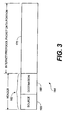
- FIG. 3 is a simplified diagram illustrating the above mentioned parts of a multimedia packet 164.
- the header 162 of a multimedia packet 164 comprises, among other portions, at least a source portion 166 that identifies a source address from which the multimedia packet arrived, and a destination portion 168, that identifies a destination address to which the packet is addressed.
- an IP header may comprise many other portions, such as, but not limited to, data provided in an RTP header or an RTCP header.
- the IP packet (164) data portion 172 of the multimedia packet comprises the remaining portion of the multimedia packet 164, which comprises data that is being transmitted to the destination device located at the destination address.
- CAM 148 ( FIG. 2 ) and the network processor 142 are used to determine the original source of a multimedia packet.
- the network processor 142 performs a series of actions on a received multimedia packet after receipt by the media router 106.
- the network processor 142 removes a level two header, such as, but not limited to, a link protocol header (a layer two header) from the received multimedia packet.
- a link protocol header may include, but is not limited to, an Ethernet header or high-level data link control (HDLC) header.
- HDLC high-level data link control
- the layer three header comprises source IP and destination IP addresses, and the layer four header comprises source and destination ports, as assigned by the session router 104 or directly assigned to the media router 106.
- the layer three and four headers may be validated and changed by the network processor 142 via use of the CAM 148, as is described below.
- FIG. 4 is a multimedia packet flow table 202 located within the CAM 148 that is utilized by the network processor 142 to enable determination of an original source of a received multimedia packet.
- the multimedia packet flow table 202 comprises a source IP address column 212, a destination IP address column 214, a source port column 216, a destination port column 218, a weight column 222, a flag column 224, and a translation addresses column 226, each of which is described below.
- each column 212, 214, 216, 218, 222, 224, 226 within the multimedia packet flow table 202 comprises a series of cells, which are utilized to store information associated with their corresponding column name. Therefore, each source IP address cell comprises a source IP address; each destination IP address cell comprises a destination IP address; each source port cell comprises a source port; each destination port cell comprises a destination port; and each translation address cell comprises replacement layer three addresses including a replacement source address and a replacement destination address. It should be noted that the translation address cell may also comprise a replacement source port and a replacement destination port, although, for simplification purposes, use of a replacement source port and a replacement destination port are not described herein.
- the weight column 222 is utilized to associate a weight value with each grouping of a source IP address, destination IP address, source port, and destination port (i. e., a first source IP address, a first destination IP address, a first source port, a first destination port). Therefore, a group comprising the first source IP address, first destination IP address, first source port and first destination port is assigned a single weight value.
- a group of cells comprising a first source IP address, a first destination IP address, a first source port and a first destination port is referred to as a first table group; a group comprising a second source IP address, a second destination IP address, a second source port and a second destination port is referred to as a second table group, etc.
- the weight value is utilized to assign priority to one table group over another table group. A detailed explanation of the weight value and a demonstration of its use is provided below.
- a universal bit represented by the variable X, may be utilized by a cell within the multimedia packet flow table 202 to represent that any value is acceptable for that particular cell.
- the universal bit is utilized within the source IP address column 212 and the source port column 216 to allow acceptance of a multimedia packet from any source. Universal bit acceptance is described below with reference to FIGS. 5A , 5B and 5C .
- the flag column 224 may provide a latch bit, designated as L, for an associated table group to indicate that multimedia packets may be received by a new source that is not yet represented by the CAM 148.
- the number of latch bits provided within the multimedia packet flow table 202 indicates the number of multimedia packet sources, not yet provided for by the CAM 148, that will be allowed to communicate with the media router 106.
- the latch bit is utilized in combination with universal bits during inspection of a received multimedia packet.
- the latch bit is utilized to specify if a new table group should be created within the CAM 148 for the received multimedia packet that comprises an acceptable destination IP address, an acceptable destination port, a newly received source IP address, and a newly received source port.
- a latch bit is associated with a table group, and a universal bit is located within both the source IP address cell of the table group and the source port cell of the table group, then the following steps are performed.
- a new table group is created wherein the value stored within the destination IP address cell of the new table group, and the value stored within the destination port cell of the new table group, is copied from the prior table group comprising the latch bit and universal bits.
- the source IP address cell of the new table group stores therein the IP address of the source of the received multimedia packet
- the source port cell of the new table group stores therein the port address of the source of the received multimedia packet.
- the weight of a table group comprising universal bits will be lower than the weight of a table group not comprising universal bits.
- the table group not having universal bits will be selected by the network processor 142 prior to the selection of a table group comprising universal bits.
- network processor 142 When a latch bit is associated with a table group, and a universal bit is located within both the source IP address cell of the table group and the source port cell of the table group, network processor 142 adds a high weight factor value to the new table group that is comparable to a weight factor value utilized for a table group not having universal bits. It should be noted that a latch flag is not set for the new table group. In addition, the network processor 142 deletes the original table group, comprising the latch bit and universal bits, from the multimedia packet flow table 202. The order of the prior mentioned steps ensures that after a first multimedia packet is received, which is defined by the original table group, the original table group is no longer utilized for allowing receipt of multimedia packets. The layer three header of multimedia packets received by the media router 106 that comprise characteristics designated by a table group is then replaced with the translation addresses associated with the table group.
- FIG. 5A provides a multimedia packet flow table 252 comprising a source IP address column 262, a destination IP address column 272, a source port column 282, a destination port column 292, a weight column 302, a flag column 312, and a translation addresses column 322.
- Each of the above mentioned columns comprises a number of cells, four of which are provided in the present example.
- Four rows of cells, or table groups, are provided by the multimedia packet flow table 252, namely, a first table group 332, a second table group 334, a third table group 336, and a fourth table group 338.
- header portion 162 of a received multimedia packet (shown in the first table group 332) comprises a source IP address of 1.1.1.1, a destination IP address of 2.2.2.2, a source port of 1001 and a destination port of 2001.
- CAM 148 returns translation addresses.
- the translation addresses 332a comprising a replacement source address and a replacement destination address, to the network processor 142.
- the translation addresses 332a associated with the first table group 332 are 10.1.1.1/20.2.2.2.
- the translated addresses 332a are incorporated into the header 162 of the received multimedia packet by the network processor 142, thereby designating a new source address of 10.1.1.1 and a new destination address of 20.2.2.2 for the received multimedia packet.
- the CAM 148 returns translation addresses 322c, comprising a replacement source address and a replacement destination address, to the network processor 142.
- the translated addresses 322c with the third table group 336 are 20.2.2.1/20.2.2.2.
- the translated addresses 322c are incorporated into the header 162 of the received multimedia packet by the network processor 142, thereby designating a new source address of 20.2.2.1 and a new destination address of 20.2.2.2 for the received multimedia packet.
- the CAM 148 returns translation addresses 322d, comprising a replacement source address and a replacement destination address, to the network processor 142.
- the translation addresses 322d associated with the fourth table group 338 are 30.3.3.3/20.2.2.2.
- the translated addresses 322d are incorporated into the header 162 of the received multimedia packet by the network processor 142, thereby designating a new source address of 30.3.3.3 and a new destination address of 20.2.2.2 for the received multimedia packet.
- the header portion 162 of a received multimedia packet comprises a source IP address designated by a universal bit, a destination IP address of 2.2.2.2, a source port designated by a universal bit, a destination port of 2001, and a set latch bit
- a fifth table group 342 is created having similar characteristics to the second table group 334. Specifically, the destination IP address (2.2.2.2), destination port (2001), and translation addresses (X/20.2.2.2) are copied from the second table group 334 to the fifth table group 342.
- the translation address, X/20.2.2.2 establish that the replacement source address is the address of the latest source of the multimedia packet and the replacement destination address is 20.2.2.2.
- the latch bit is not set in the fifth table group 342 and the weight for the fifth table group 342 is set to be equivalent or similar to other table groups 332, 336, 338.
- the IP address and port of the device that last transmitted the received multimedia packet to the media router 106 is stored in the source IP address column 262 and the source port column 282, respectively, within the fifth table group 342. As is shown by FIG. 5C , information within the second table group 334 is then deleted from the multimedia packet flow table 252. Since the fifth table group 342 comprises a source IP address, destination IP address, source port, destination port, weight, and translation addresses, the fifth table group 342 is capable of being used to direct a received multimedia packet to a destination.
- the media router 106 will no longer accept multimedia packets from a device that does not comprise a source IP address, destination IP address, source port and destination port combination, defined by a single table group.
- the media router 106 may transmit the source IP address and source port to the session router 104.
- the session router 104 may then be utilized to determine additional information about the source of the received multimedia packet such as, whether the latched source address is valid.
- the media router 106 will inform the session router 104 of the latched source address using the protocol used for flow setup and tear-down.
- more than one combination of universal bits and latch flags may be utilized within the multimedia packet flow table 252 to allow the introduction of more than one new source device for communication with the media router 106.
Description
- The present invention generally relates to telecommunications and, more particularly, is related to a system and method for determining a source of a received Internet protocol packet.
- The public switched telephone network (PSTN) has evolved into an efficient real-time, multimedia communication session tool, wherein users can pick up any one of nearly one billion telephones and dial any one of nearly one billion endpoints. Several developments have enabled this automated network, such as numbering plans, distributed electronic switching and routing, and networked signaling systems.
- Similar to the manner in which the PSTN is based on a hierarchy, the Internet is based on an Internet protocol (IP). IP messages, or multimedia packets, are routed or forwarded from a source of a multimedia flow to a destination of the multimedia flow. Each multimedia packet comprises an IP address, which, in Internet protocol version 4 (IPv4), for example, has 32 bits. Each IP address also has a certain number of bits dedicated to a network portion and a certain number of bits dedicated to a host portion. It should be noted that the term "multimedia" utilized herein is intended to comprise one or more of the following: voice, data, text, graphics, animation, and/or discrete media.
- More specifically, multimedia packets comprise a header portion and an IP packet data portion. The header portion of the multimedia packet, at a minimum, comprises at least a source portion and a destination portion, wherein the source portion identifies a source address from which the packet originated, and the destination portion identifies a destination address to which the packet is addressed. It should be noted that additional portions of the header portion may be provided, in addition to the source portion and the destination portion such as, but not limited to, a real-time packet header or a real-time control packet header. The IP packet data portion of the multimedia packet comprises the remaining portion of the multimedia packet, which comprises data that is being transmitted to a destination device located at the destination address.
- As the multimedia packet is received by different devices on a path taken by the multimedia packet to the destination device, it is common for the source and/or destination portions of the multimedia packet to change properties, thereby reflecting a most recent source and destination.
- Therefore, it is difficult to determine the original source of a multimedia packet. Having knowledge of the original source of a multimedia packet allows the destination device to accept or decline the multimedia packet based upon the original source of the multimedia packet.
- The acceptance or denial of multimedia packets based upon the original source is a characteristic of devices such as, but not limited to, firewalls. Unfortunately, since the header portion of the multimedia packet is changed by devices within the transmission path to the destination device, the original source of the multimedia packet is not known. Since the original source is not known, the destination device is incapable of accurately declining receipt of multimedia packets from a predefined source. The document "A multihoming solution using NATs" by Akkiraju et al, XP015009988, discusses use of NATs to address the problems with Multihoming. The document "Midcom-unaware NAT/Firewall Traversal" by Sen et al, XP015035109, discusses allowing a Middlebox to be controlled through a generalized control interface by an application-aware entity.
WO 01/97449 WO 00/33204 - According to an aspect of the present invention, there is provided a method according to claim 1 or a system according to claim 7.
- Other systems and methods of the present invention will be or become apparent to one with skill in the art upon examination of the following drawings and detailed description. It is intended that all such additional systems, methods, features, and advantages be included within this description, be within the scope of the present invention, and be protected by the accompanying claims.
- The invention can be better understood with reference to the following drawings. The components of the drawings are not necessarily to scale, emphasis instead being placed upon clearly illustrating the principles of the present invention. Moreover, in the drawings, like referenced numerals designate corresponding parts throughout the several views.
-
FIG. 1 is a block diagram illustrating a communication network for providing a source determination system. -
FIG. 2 is a block diagram further illustrating the media router ofFIG. 1 . -
FIG. 3 is a simplified diagram illustrating parts of a multimedia packet that may be received by the media router ofFIG. 2 . -
FIG. 4 is a multimedia packet flow table located within a CAM of the media router ofFIG. 2 . -
FIG. 5A is a block diagram illustrating a multimedia packet flow table that exemplifies operation of the source determination system. -
FIG. 5B is a block diagram illustrating the multimedia packet flow table ofFIG. 5A after addition of a fifth table group. -
FIG. 5C is a block diagram illustrating the multimedia packet flow table ofFIG. 5B after removal of a second table group. - The source determination system of the present invention can be implemented in software, firmware, hardware, or a combination thereof. In the preferred embodiment of the invention, which is intended to be a non-limiting example, a portion of the system is implemented in software that is executed by a network processor.
- The software based portion of the source determination system, which comprises an ordered listing of executable instructions for implementing logical functions, can be embodied in any computer-readable medium for use by, or in connection with, an instruction execution system, apparatus, or device such as a computer-based system processor containing system, or other system that can fetch the instructions from the instruction execution system, apparatus, or device and execute the instructions. In the context of this document, a "computer-readable medium" can be any means that can contain, store, communicate, propagate or transport the program for use by or in connection with the instruction execution system, apparatus or device.
- The computer-readable medium can be, for example, but not limited to, an electronic, magnetic, optical, electromagnetic, infrared, or semiconductor system, apparatus, device, or propagation medium. More specific examples (a non-exhaustive list) of the computer-readable medium would include the following: an electrical connection (electronic) having one or more wires, a portable computer diskette (magnetic), a random access memory (RAM) (magnetic), a read-only memory (ROM) (magnetic), an erasable programmable read-only memory (EPROM or Flash memory) (magnetic), an optical fiber (optical), and a portable compact disk read-only memory (CD ROM) (optical). Note that the computer-readable medium could even be paper or another suitable medium upon which the program is printed, as the program can be electronically captured, via for instance, optical scanning of the paper or other medium, then compiled, interpreted or otherwise processed in a suitable manner, if necessary, and then stored in a computer memory.
- In the transmission of multimedia data packets from a first endpoint to a second endpoint, it is desirable to process multiple transmission routes and to select a best transmission route. A session router selects multiple routes and processes them in order, selecting from a set of session initiation protocol (SIP) agent(s) that are otherwise equal using various distribution strategies. This process leads to managing the path of the resulting real-time transport protocol (RTP) flow. Media routers are configured for guiding the resulting RTP flows selected and processed by the session router through certain thresholds. The combination of the session router and the media router creates a high-quality border between various IP networks. Without the session and media routers, data packets would flow whichever way the underlying network backbone would allow.
-
FIG. 1 is a block diagram illustrating acommunication network 102, wherein the use of a session router 104 andmedia router 106 is demonstrated, for implementation of the present source determination system. As shown byFIG. 1 , a first session initiation protocol (SIP)device 112, herein a SIP phone, such as those produced by and commercially available from the Pingtel Corporation of Woburn, Massachusetts, U.S.A., is connected to asecond SIP device 114, herein a second SIP phone. Communication between thefirst SIP phone 112 and asecond SIP phone 114 is enabled by the session router 104 anintervening device 116 and themedia router 106 operable on a wide area network (WAN) such as the Internet. It should be noted that communication between thefirst SIP phone 112 and thesecond SIP phone 114 may instead be provided via a proprietary network or a local area network (LAN). In an alternative network structure, thefirst SIP phone 112 and thesecond SIP phone 114 may be coupled in a data network domain. For example, themedia router 106 can be used between two domains coupled to the Internet, with thefirst SIP phone 112 in a first domain and thesecond SIP phone 114 is a second domain. - The session router 104 provides SIP and telephony routing over IP (TRIP) protocol support. It should be noted that additional session routers and media routers may be provided within the
communication network 102. In fact, communication from a first media router may be to a second media router, a session router, a SIP device, and/or a non-SIP device located in a LAN, WAN, or other location.FIG. 1 illustrates acommunication system 102 with a single destination device, that is, thesecond SIP phone 114, it should be understood multiple destination devices may be connected to thefirst SIP phone 112 via themedia router 106. - The introduction of media routers into the real-time multimedia flow forces multimedia packets through a known interface.
FIG. 2 is a block diagram further illustrating themedia router 106 ofFIG. 1 . As shown byFIG. 2 , themedia router 106 comprises a flowquality management engine 132, atraffic manager 134, acommunication interface 136, ahost processor 138, anetwork processor 142,input devices 144,output devices 146, and a content addressable memory (CAM) 148, or a ternary database, all of which communicate within themedia router 106 via alocal link 152. - The
traffic manager 134 measures and enforces IP session multimedia data packet traffic, or traffic, including packet flow rates. An example of a suitable traffic manager among the many possible implementations is the NPX5700 traffic manager commercially available from MMC Networks Corporation of San Diego, California, USA. Essentially, thetraffic manager 134 measures the number of multimedia packets that flow through thecommunication interface 136. Thetraffic manager 134 works in concert with thenetwork processor 142 such that once a forwarding decision is made, thetraffic manager 134 queues the received packet into its respective IP flow in accordance with an associated priority. - As is known in the art, the
traffic manager 134 comprises a memory for temporarily storing received multimedia packets. From an inbound perspective, thetraffic manager 134 is able to monitor RTP multimedia flows and enforce maximum data rates by either dropping multimedia packets or marking them as eligible for discarding if they are outside a bandwidth allocated for the multimedia flow. Thetraffic manager 134 may also be instructed by the session router 104 to accept a specific amount of multimedia data over a specific period of time in accordance with an allocated bandwidth and bit rate. Therefore, if multimedia data is received at a higher bit rate than allowed by the session router 104, the multimedia data received at the higher bit rate is not transmitted. It should be noted that the characteristics specified by the session router 104 may instead be programmed directly into themedia router 106 thereby making it possible to control RTP multimedia data flow without session router 104. - The
network processor 142 provides translation services within themedia router 106. The translation services performed by thenetwork processor 142 comprise the capability to translate a source address, destination address, source port, destination port or any combination of these fields. In addition, thenetwork processor 142 is capable of removing and/or inserting a multi-protocol label switching (MPLS) tag in a multimedia packet. In addition, thenetwork processor 142 is capable of inserting or modifying a diffserv codepoint located within the IP header of a multimedia packet, which is used to modify indicia of a designated processing priority associated with the multimedia packets. - The flow
quality management engine 132 provides quality measurement services on a per flow basis, wherein a multimedia flow is defined by a source IP address, a destination IP address, a source port, and/or a destination port. Quality measurement preferably comprises maintaining current statistics for the flow within thenetwork processor 142, as well as aggregate and/or min/max statistics for the flow where applicable. - Examples of statistics that may be collected include latency, jitter, and packet loss for a pre-defined window of time. It should be noted that the window can be identified via the session router 104 or the
media router 106. Aggregate statistics may include transmitted packets, dropped packets, and/or duplicate packets. Minimum and maximum statistics, otherwise referred to as "boundary statistics," may also be collected which may include latency, jitter, and packet loss per window of time. The flowquality management engine 132 also enables detection and correction of upstream and/or downstream failures in the transmission of RTP data packets. - The
host processor 138, similar to thetraffic manager 134, also enables detection and correction of upstream and downstream failures. Thehost processor 138 detects upstream and downstream failures in the transmission of RTP multimedia packets by identifying link failures.Host processor 138 is further configured to handle multimedia data packets in accordance with external management events. - The
CAM 148 stores translations or bindings in accordance with "open/bin" requests for fast access by thenetwork processor 142. TheCAM 148 may also be used to store media access control addresses to IP mappings as discussed below. There are many possible implementations of theCAM 148. - The
media router 106 is capable of generating flow quality statistics for RTP multimedia flows. Further, themedia router 106 is able to generate the flow quality statistics from RTP packets as they flow through thecommunication network 102. In certain situations the statistics are only relevant for links between media routers if more than one media router is utilized. - Preferably, the
media router 106 stores one or more statistics for each flow. These statistics may include, but are not limited to, latency, jitter, a number of octets per packet, and/or the number of dropped packets. It should be noted that other statistics may also be stored with regard to each multimedia flow through themedia router 106. Assuming that more than one media router is utilized, to generate statistics for each multimedia flow, themedia router 106 runs a proprietary version of a protocol, such as, but not limited to, real-time transport control protocol (RTCP), between connected media routers to determine latency. Jitter and dropped packet statistics can be generated autonomously by themedia router 106. The following describes how latency, jitter and dropped packets can be determined in the absence of RTCP information. - In order to measure latency for a data flow, the
media router 106 communicates with another endpoint on the multimedia flow. The other endpoint may be another media router, although it need not be. As an example, the other endpoint may be a SIP phone. Assuming, for exemplary purposes, that the other endpoint is a media router, the subject of the communication between media routers is a test packet that is utilized to determine RTP data flow latency. Themultimedia router 106 receiving the looped packet compares when the packet was received to when the packet was sent, thereby determining a round trip time. The round trip time is then cut in half to approximate the one-way time, which is the latency. - Rather than using a proprietary method to perform packet looping, a modified RTCP packet format can be used between two media routers. This modified format enables the extraction of a timestamp associated with of the sender (e.g., as provided in a send report) and placement of the timestamp into the looped packet (e.g., in a receive report), to enable a receiving device to estimate how long it took to loop the packet.
- Jitter is a measurement of the variation of the gap between packets on a flow. An alternative definition is that jitter is the variance in latency for a multimedia flow. The
media router 106 can measure jitter for an RTP data flow as it transits themedia router 106. When a data packet reaches thenetwork processor 142, a timer is started that runs until the next packet for that RTP data flow arrives. The time gap between the received times of adjacently ordered packets is added to an aggregate to maintain a "mean" jitter value. The "mean" jitter value can also be compared to a min/max value in a flow record to determine if a new min/max jitter value is established. It should be noted that the flow record may be located within a network processor memory (not shown) that is located within thenetwork processor 142. It should also be noted that the memories located within themedia router 106 may all be located within a single memory device within, or outside of themedia router 106. When jitter processing is processor intensive, jitter samples can be aggregated and min/max calculations can be performed on a periodic basis using the aggregated information. - Dropped packet, or lost packet, processing in the absence of an RTCP based mechanism may be accomplished on an RTP flow using two scoreboard arrays of booleans that are used to track when a packet is missing, and whether the packet appears within a jitter window. Alternate methods of processing multimedia packets may be used. It should be noted that a jitter window is typically implemented in voice gateways to compensate for fluctuating network conditions. The jitter window is a packet buffer that holds incoming packets for a specified amount of time, before forwarding them for decompression. The process has the effect of smoothing the packet flow, thereby increasing the resiliency of a compressor/de-compressor (CODEC) to packet loss, delaying packets, and producing other transmission effects. Preferably, the jitter window is defined by the session router 104, although it may be defined via the
media router 106. - Each entry in a scoreboard array represents whether a media router has received a packet having a specific sequence number. The scoreboard array may be located within the network processor memory or within any local or distant memory. Each scoreboard array also has a counter which tracks how many entries have been marked "missing." Preferably, all entries are initially marked as "received."
- As the sequence numbers are tracked in the
network processor 142 and missing packets are detected, specifically, a packet with a sequence number that has incremented more than one with respect to the sequence number of the preceding received packet, the appropriate entry in the current array is marked "missing" and the missing counter is incremented. Preferably, two arrays are sized as the maximum number of packets in the jitter window. These two arrays are hereinafter referred to as the current array and the aged array. When the current array reaches the maximum jitter window, the aged array is re-initialized and becomes the current array and the current array becomes the aged array. Before the aged array is erased, the counter for dropped packets is retrieved and accumulated for the data flow. - However, if an out of order old multimedia packet is received, wherein the sequence number is less than the current sequence number, the
network processor 142 searches for the sequence number entry in either the current or aged array, depending on lateness of the packet. If thenetwork processor 142 finds the entry marked missing and changes the entry, thenetwork processor 142 then decrements a missing multimedia packet counter of the array that is used for keeping track of missing packets. If the packet is not marked as missing, then thenetwork processor 142 designates that the packet is a duplicate. If the sequence number is so old that the multimedia packet dates back further than the depth of the jitter window, then thenetwork processor 142 does not perform a lookup. It should be noted that this method of performing dropped packet counting is more accurate than that obtainable using RTCP. - Returning to
FIG. 1 , typically, there is at least oneintervening device 116 located between thefirst SIP phone 112 and themedia router 106. The interveningdevice 116 can be a border router, a frewall, or any other communication device. It should be noted, however, that an additional router, such as a border router, is not necessary in order for thefirst SIP phone 112 and thesecond SIP phone 114 to communicate. - Multimedia packets received by the
media router 106 comprise, among other portions, a header and an IP packet (164) data portion.FIG. 3 is a simplified diagram illustrating the above mentioned parts of amultimedia packet 164. Theheader 162 of amultimedia packet 164, at a minimum, comprises, among other portions, at least asource portion 166 that identifies a source address from which the multimedia packet arrived, and adestination portion 168, that identifies a destination address to which the packet is addressed. As described above, an IP header may comprise many other portions, such as, but not limited to, data provided in an RTP header or an RTCP header. The IP packet (164)data portion 172 of the multimedia packet comprises the remaining portion of themultimedia packet 164, which comprises data that is being transmitted to the destination device located at the destination address. - CAM 148 (
FIG. 2 ) and thenetwork processor 142 are used to determine the original source of a multimedia packet. Thenetwork processor 142 performs a series of actions on a received multimedia packet after receipt by themedia router 106. Generally, thenetwork processor 142 removes a level two header, such as, but not limited to, a link protocol header (a layer two header) from the received multimedia packet. An example of a link protocol header may include, but is not limited to, an Ethernet header or high-level data link control (HDLC) header. The layer two header is removed so that a layer three header located within the data packet, and a layer four header located within the data packet, may be examined by themedia router 106. The layer three header comprises source IP and destination IP addresses, and the layer four header comprises source and destination ports, as assigned by the session router 104 or directly assigned to themedia router 106. The layer three and four headers may be validated and changed by thenetwork processor 142 via use of theCAM 148, as is described below. -
FIG. 4 is a multimedia packet flow table 202 located within theCAM 148 that is utilized by thenetwork processor 142 to enable determination of an original source of a received multimedia packet. As is shown byFIG. 4 , the multimedia packet flow table 202 comprises a sourceIP address column 212, a destinationIP address column 214, asource port column 216, adestination port column 218, aweight column 222, aflag column 224, and a translation addressescolumn 226, each of which is described below. - Each
column - The
weight column 222 is utilized to associate a weight value with each grouping of a source IP address, destination IP address, source port, and destination port (i. e., a first source IP address, a first destination IP address, a first source port, a first destination port). Therefore, a group comprising the first source IP address, first destination IP address, first source port and first destination port is assigned a single weight value. Hereinafter, a group of cells comprising a first source IP address, a first destination IP address, a first source port and a first destination port is referred to as a first table group; a group comprising a second source IP address, a second destination IP address, a second source port and a second destination port is referred to as a second table group, etc. The weight value is utilized to assign priority to one table group over another table group. A detailed explanation of the weight value and a demonstration of its use is provided below. - A universal bit, represented by the variable X, may be utilized by a cell within the multimedia packet flow table 202 to represent that any value is acceptable for that particular cell. Specific to the present source determination system, the universal bit is utilized within the source
IP address column 212 and thesource port column 216 to allow acceptance of a multimedia packet from any source. Universal bit acceptance is described below with reference toFIGS. 5A ,5B and5C . - The
flag column 224 may provide a latch bit, designated as L, for an associated table group to indicate that multimedia packets may be received by a new source that is not yet represented by theCAM 148. In fact, the number of latch bits provided within the multimedia packet flow table 202 indicates the number of multimedia packet sources, not yet provided for by theCAM 148, that will be allowed to communicate with themedia router 106. The latch bit is utilized in combination with universal bits during inspection of a received multimedia packet. The latch bit is utilized to specify if a new table group should be created within theCAM 148 for the received multimedia packet that comprises an acceptable destination IP address, an acceptable destination port, a newly received source IP address, and a newly received source port. - If a latch bit is associated with a table group, and a universal bit is located within both the source IP address cell of the table group and the source port cell of the table group, then the following steps are performed. First, a new table group is created wherein the value stored within the destination IP address cell of the new table group, and the value stored within the destination port cell of the new table group, is copied from the prior table group comprising the latch bit and universal bits. In addition, the source IP address cell of the new table group stores therein the IP address of the source of the received multimedia packet, and the source port cell of the new table group stores therein the port address of the source of the received multimedia packet.
- Preferably, the weight of a table group comprising universal bits will be lower than the weight of a table group not comprising universal bits. As a result, the table group not having universal bits will be selected by the
network processor 142 prior to the selection of a table group comprising universal bits. - When a latch bit is associated with a table group, and a universal bit is located within both the source IP address cell of the table group and the source port cell of the table group,
network processor 142 adds a high weight factor value to the new table group that is comparable to a weight factor value utilized for a table group not having universal bits. It should be noted that a latch flag is not set for the new table group. In addition, thenetwork processor 142 deletes the original table group, comprising the latch bit and universal bits, from the multimedia packet flow table 202. The order of the prior mentioned steps ensures that after a first multimedia packet is received, which is defined by the original table group, the original table group is no longer utilized for allowing receipt of multimedia packets. The layer three header of multimedia packets received by themedia router 106 that comprise characteristics designated by a table group is then replaced with the translation addresses associated with the table group. - An example of a multimedia packet flow table 252 is provided by
FIGS. 5A ,5B , and5C for purposes of demonstrating the above mentioned steps.FIG. 5A provides a multimedia packet flow table 252 comprising a sourceIP address column 262, a destinationIP address column 272, asource port column 282, adestination port column 292, aweight column 302, aflag column 312, and a translation addressescolumn 322. Each of the above mentioned columns comprises a number of cells, four of which are provided in the present example. Four rows of cells, or table groups, are provided by the multimedia packet flow table 252, namely, afirst table group 332, asecond table group 334, athird table group 336, and afourth table group 338. - In the example illustrated in
FIG. 5A ,header portion 162 of a received multimedia packet (shown in the first table group 332) comprises a source IP address of 1.1.1.1, a destination IP address of 2.2.2.2, a source port of 1001 and a destination port of 2001. In response to these values,CAM 148 returns translation addresses. The translation addresses 332a, comprising a replacement source address and a replacement destination address, to thenetwork processor 142. As shown inFIG. 5A , the translation addresses 332a associated with thefirst table group 332 are 10.1.1.1/20.2.2.2. The translated addresses 332a are incorporated into theheader 162 of the received multimedia packet by thenetwork processor 142, thereby designating a new source address of 10.1.1.1 and a new destination address of 20.2.2.2 for the received multimedia packet. - When the
header portion 162 of a received multimedia packet comprises a source IP address of 2.2.2.1, a destination IP address of 2.2.2.2, a source port of 3000 and a destination port of 2001 (shown in the third table group 336), theCAM 148 returns translation addresses 322c, comprising a replacement source address and a replacement destination address, to thenetwork processor 142. As shown byFIG. 5A , the translated addresses 322c with thethird table group 336 are 20.2.2.1/20.2.2.2. The translated addresses 322c are incorporated into theheader 162 of the received multimedia packet by thenetwork processor 142, thereby designating a new source address of 20.2.2.1 and a new destination address of 20.2.2.2 for the received multimedia packet. - When the
header portion 162 of a received multimedia packet comprises a source IP address of 3.3.3.3, a destination IP address of 2.2.2.2, a source port of 5000 and a destination port of 2001 (as shown in the fourth table group 338), theCAM 148 returns translation addresses 322d, comprising a replacement source address and a replacement destination address, to thenetwork processor 142. As shown byFIG. 5A , the translation addresses 322d associated with thefourth table group 338 are 30.3.3.3/20.2.2.2. The translated addresses 322d are incorporated into theheader 162 of the received multimedia packet by thenetwork processor 142, thereby designating a new source address of 30.3.3.3 and a new destination address of 20.2.2.2 for the received multimedia packet. - Alternatively, if the
header portion 162 of a received multimedia packet comprises a source IP address designated by a universal bit, a destination IP address of 2.2.2.2, a source port designated by a universal bit, a destination port of 2001, and a set latch bit, the following occurs. As is shown byFIG. 5B , afifth table group 342 is created having similar characteristics to thesecond table group 334. Specifically, the destination IP address (2.2.2.2), destination port (2001), and translation addresses (X/20.2.2.2) are copied from thesecond table group 334 to thefifth table group 342. It should be noted that the translation address, X/20.2.2.2, establish that the replacement source address is the address of the latest source of the multimedia packet and the replacement destination address is 20.2.2.2. The latch bit is not set in thefifth table group 342 and the weight for thefifth table group 342 is set to be equivalent or similar toother table groups - The IP address and port of the device that last transmitted the received multimedia packet to the
media router 106, is stored in the sourceIP address column 262 and thesource port column 282, respectively, within thefifth table group 342. As is shown byFIG. 5C , information within thesecond table group 334 is then deleted from the multimedia packet flow table 252. Since thefifth table group 342 comprises a source IP address, destination IP address, source port, destination port, weight, and translation addresses, thefifth table group 342 is capable of being used to direct a received multimedia packet to a destination. In addition, since the latch bit is no longer set within the multimedia packet flow table 252 and the universal bits within the sourceIP address column 262 and thesource port column 282 have been deleted, themedia router 106 will no longer accept multimedia packets from a device that does not comprise a source IP address, destination IP address, source port and destination port combination, defined by a single table group. - After the new source IP address and source port have been determined, the
media router 106 may transmit the source IP address and source port to the session router 104. The session router 104 may then be utilized to determine additional information about the source of the received multimedia packet such as, whether the latched source address is valid. Themedia router 106 will inform the session router 104 of the latched source address using the protocol used for flow setup and tear-down. In addition, it should be noted that more than one combination of universal bits and latch flags may be utilized within the multimedia packet flow table 252 to allow the introduction of more than one new source device for communication with themedia router 106. - It should be emphasized that the above-described embodiments of the present invention, particularly, any "preferred" embodiments, are merely possible examples of implementations, merely set forth for a clear understanding of the principles of the invention. Many variations and modifications may be made to the above-described embodiment(s) of the invention without departing from the scope of the invention. All such modifications and variations are intended to be included herein within the scope of this disclosure and the present invention and protected by the following claims.
Claims (10)
- A method of detecting a new Internet protocol (IP) packet (164) from a source not yet present in a multimedia packet flow table (202), comprising:comparing a destination address and a destination port of the IP packet (164) to the contents of a first destination address cell (214a) and a first destination port cell (218a) of an existing table group (334), respectively;comparing a source address and a source port of the IP packet (164) to the contents of a first source address cell (212a) and a first source port cell (216a) of the existing table group (334), respectively;creating a new table group (342) when:the destination address and the destination port of the IP packet (164) match the contents of the first destination address cell (214a) and the first destination port cell (218a) of the existing table group (334), respectively;the source address and the source port of the IP packet (164) do not match the contents of the first source address cell (212a) and the first source port cell (216a) of the existing table group (334), respectively;a latch bit in a flag cell (224) of the existing table group (334) is set; andthe first source address cell (212a) and the first source port cell (216a) of the existing table group (334) comprise universal bits that accept any value; thencopying a translation addresses cell (322b) of the existing table group (334) to a translation addresses cell (322e) of the new table group (342), wherein universal bits in the source address of the translation addresses cell (322b) establish that the replacement source address in the translation addresses cell (322e) is the source address of the IP packet (164); andclearing the latch bit in the flag cell of the new table group (342).
- The method of claim 1, further comprising:removing a first header from the IP packet (164), wherein the first header comprises the source address of the IP packet (164) and the destination address of the IP packet (164);removing a second header from the IP packet (164), wherein the second header comprises the source port of the IP packet (164) and the destination port of the IP packet (164);replacing the source address, the destination address, the source port, and the destination port of the IP packet (164) with translation addresses (226) when the source address, the destination address, the source port, and the destination port of the IP packet (164) are the same as the contents of the first source address cell (212a), the first destination address cell (214a), the first source port cell (216a), and the first destination port cell (218a), respectively.
- The method of claim 1, further comprising:replacing the source address, the destination address, the source port, and the destination port of the IP packet (164) with translation addresses (226) when the destination address and the destination port of the IP packet (164) are the same as the contents of the first destination address cell (214a), the first destination port cell (218a), respectively, and the first source address cell (212a) and the first source port cell (216a) comprise universal bits.
- The method of claim 1, further comprising:comparing the source address, source port, destination address, and destination port of the IP packet (164) to corresponding cells of the existing table group (334) and corresponding cells of the existing table group (342); and when the source address, source port, destination address, and destination port of the IP packet (164) match the contents of respective cells in the existing table group (334), and the destination address and destination port of the IP packet (164) are the same as the contents of the second destination address cell and the second destination port cell, respectively,comparing a first weight value to a second weight value, andleaving the source address and the source port of the IP packet (164) unchanged when the first weight value is larger than the second weight value.
- The method of claim 1, further characterized by deleting the contents of a plurality of cells within the existing table group (334).
- The method of claim 5, wherein a first weight value is associated with the existing table group (334), and wherein the new table group (342) is assigned a new weight value that is higher than the first weight value.
- A system for detecting a new Internet protocol (IP) packet (164) from a source not yet present in a multimedia packet flow table (202), comprising:a content addressable memory (148) comprising:a table group (332), the table group (332) further comprising:a source address cell (262);a destination address cell (272);a source port cell (282);a destination port cell (292);a latch bit in a flag cell (312);a translation addresses cell (322); andan instruction set; anda network processor (142) coupled to the content addressable memory (148) and configured to execute the instruction set, wherein when the network processor (142) executes the instruction set, the network processor (142) compares information extracted from a header (162) of the received IP packet (164) with respective information stored in the source address (262), destination address (272), source port (282), and destination port (292) cells of an existing table group (334),
whereinsaid network processor (142) is further configured to create a new table group (342) when:the destination address (168) and the destination port in the header (162) match the contents of the destination address cell (272) and the destination port cell (292) of the existing table group (334), respectively;the source address (166) and the source port in the header (162) do not match the contents of the source address cell (262) and the source port cell (282) of the existing table group, respectively;the source address cell (262) and the source port cell (282) of the existing table group comprise universal bits that accept any value; andthe latch bit in the flag cell (312) is set;said network processor (142) is further configured to:copy a translation addresses cell (322b) of the existing table group (334) to a translation addresses cell (322e) of the new table group (342), wherein universal bits in the source address of the translation addresses cell (322b) establish that the replacement source address in the translation addresses cell (322e) is the source address of the IP packet (164); andclear the latch bit in the flag cell of the new table group (342). - The system of claim 7, wherein said network processor (142) is further configured to compare the source address, source port, destination address, and destination port of the IP packet (164) to corresponding cells of the existing table group (334) and corresponding cells of the existing table group (342); and when the source address, source port, destination address, and destination port of the IP packet (164) match the contents of respective cells in the existing table group (332), and the destination address and destination port of the IP packet (164) match the contents of the second destination address cell and the second destination port cell, respectively, the network processor (142) compares the first weight value to the second weight value, and leaves the source address and the source port of the IP packet (164) unchanged when the first weight value is larger than the second weight value.
- The system of claim 7, further characterized in that said network processor (142) is further configured to delete the contents of the source address cell (262), the destination address cell (272), the source port cell (282), and the destination port cell (292) within the existing table group (334).
- The system of claim 9, wherein the first weight value is associated with the existing table group (334), and wherein the new table group (342) is assigned a new weight value that is higher than the first weight value.
Applications Claiming Priority (2)
| Application Number | Priority Date | Filing Date | Title |
|---|---|---|---|
| US85324 | 2002-02-28 | ||
| US10/085,324 US7193996B2 (en) | 2002-02-28 | 2002-02-28 | System and method for determining a source of an internet protocol packet |
Publications (3)
| Publication Number | Publication Date |
|---|---|
| EP1341359A2 EP1341359A2 (en) | 2003-09-03 |
| EP1341359A3 EP1341359A3 (en) | 2004-05-19 |
| EP1341359B1 true EP1341359B1 (en) | 2014-07-16 |
Family
ID=27733381
Family Applications (1)
| Application Number | Title | Priority Date | Filing Date |
|---|---|---|---|
| EP03003010.0A Expired - Lifetime EP1341359B1 (en) | 2002-02-28 | 2003-02-12 | System and method for determining the source of an internet protocol packet |
Country Status (3)
| Country | Link |
|---|---|
| US (1) | US7193996B2 (en) |
| EP (1) | EP1341359B1 (en) |
| JP (1) | JP4287168B2 (en) |
Families Citing this family (41)
| Publication number | Priority date | Publication date | Assignee | Title |
|---|---|---|---|---|
| US7139841B1 (en) | 2002-07-24 | 2006-11-21 | Cisco Technology, Inc. | Method and apparatus for handling embedded address in data sent through multiple network address translation (NAT) devices |
| US7454525B1 (en) * | 2002-12-05 | 2008-11-18 | Cisco Technology, Inc. | Enabling communication when signaling protocol packets contain embedded addresses subject to translation |
| US7571210B2 (en) | 2002-12-06 | 2009-08-04 | Insors Integrated Communications | Methods and systems for linking virtual meeting attendees over a network |
| US8095409B2 (en) * | 2002-12-06 | 2012-01-10 | Insors Integrated Communications | Methods and program products for organizing virtual meetings |
| TW200412101A (en) * | 2002-12-23 | 2004-07-01 | Shaw-Hwa Hwang | Directly peer-to peer transmission protocol between two virtual network |
| US7634805B2 (en) * | 2003-03-05 | 2009-12-15 | Microsoft Corporation | Use of network address translation for implementation of stateful routing |
| US7949116B2 (en) * | 2003-05-22 | 2011-05-24 | Insors Integrated Communications | Primary data stream communication |
| US7613137B2 (en) * | 2003-05-22 | 2009-11-03 | Insors Integrated Communications | Data stream communication |
| US8767704B2 (en) * | 2003-10-17 | 2014-07-01 | Nokia Solutions And Networks Oy | Compressing header data |
| US7487239B2 (en) * | 2004-03-25 | 2009-02-03 | International Business Machines Corporation | Composite resource models |
| US7701884B2 (en) * | 2004-04-19 | 2010-04-20 | Insors Integrated Communications | Network communications bandwidth control |
| US7567270B2 (en) * | 2004-04-22 | 2009-07-28 | Insors Integrated Communications | Audio data control |
| JP4266188B2 (en) * | 2004-06-30 | 2009-05-20 | 株式会社東芝 | COMMUNICATION SYSTEM, COMMUNICATION TERMINAL DEVICE USED IN THIS COMMUNICATION SYSTEM, AND COMMUNICATION METHOD USED IN COMMUNICATION SYSTEM |
| ATE361627T1 (en) * | 2004-07-16 | 2007-05-15 | Alcatel Lucent | METHOD FOR SECURING COMMUNICATIONS IN A LOCAL NETWORK EXCHANGE |
| US8059562B2 (en) * | 2004-10-18 | 2011-11-15 | Nokia Corporation | Listener mechanism in a distributed network system |
| US8194640B2 (en) * | 2004-12-31 | 2012-06-05 | Genband Us Llc | Voice over IP (VoIP) network infrastructure components and method |
| US7961731B2 (en) * | 2005-03-31 | 2011-06-14 | Alcatel-Lucent Usa Inc. | Method and system for real-time detection of hidden traffic patterns |
| US20070291734A1 (en) * | 2005-05-27 | 2007-12-20 | Medhavi Bhatia | Methods and Apparatus for Multistage Routing of Packets Using Call Templates |
| US7502320B2 (en) * | 2005-07-06 | 2009-03-10 | Cisco Technology, Inc. | Method and apparatus for network-based admission control using path-coupled quality of service signaling |
| US7885330B2 (en) * | 2005-07-12 | 2011-02-08 | Insors Integrated Communications | Methods, program products and systems for compressing streaming video data |
| JP4677340B2 (en) * | 2005-12-21 | 2011-04-27 | キヤノン株式会社 | Information processing apparatus, information processing method, program, and storage medium |
| US9060047B2 (en) | 2005-12-21 | 2015-06-16 | Genband Us Llc | Media stream management |
| JP2007201884A (en) * | 2006-01-27 | 2007-08-09 | Sony Corp | Information processing apparatus and method, as well as program |
| US7861003B2 (en) | 2006-01-31 | 2010-12-28 | Genband Us Llc | Adaptive feedback for session over internet protocol |
| US7860990B2 (en) * | 2006-01-31 | 2010-12-28 | Genband Us Llc | Session data records and related alarming within a session over internet protocol (SOIP) network |
| US7865612B2 (en) * | 2006-01-31 | 2011-01-04 | Genband Us Llc | Method and apparatus for partitioning resources within a session-over-internet-protocol (SoIP) session controller |
| US8259706B2 (en) * | 2006-02-28 | 2012-09-04 | Genband Us Llc | Multistage prioritization of packets within a session over internet protocol (SOIP) network |
| US8509218B2 (en) * | 2006-02-28 | 2013-08-13 | Genband Us Llc | Prioritization within a session over internet protocol (SOIP) network |
| US8204043B2 (en) * | 2006-02-28 | 2012-06-19 | Genband Us Llc | Quality of service prioritization of internet protocol packets using session-aware components |
| CN1937531B (en) * | 2006-08-28 | 2010-05-12 | 华为技术有限公司 | Method and device for detecting and maintaining group integrity, and end increasing method and device |
| WO2008113791A1 (en) * | 2007-03-20 | 2008-09-25 | Thomson Licensing | Virtual multimedia matrix over packet switched network |
| CN101309235A (en) * | 2007-05-18 | 2008-11-19 | 华为技术有限公司 | Method for forwarding packet, media gateway controller, media gateway and network system |
| WO2008148099A1 (en) * | 2007-05-25 | 2008-12-04 | New Jersey Institute Of Technology | Method and system to mitigate low rate denial of service (dos) attacks |
| US7912062B2 (en) | 2007-09-28 | 2011-03-22 | Genband Us Llc | Methods and apparatus for managing addresses related to virtual partitions of a session exchange device |
| US7738361B2 (en) * | 2007-11-15 | 2010-06-15 | Lockheed Martin Corporation | Method and apparatus for generating fill frames for voice over internet protocol (VoIP) applications |
| JP5205075B2 (en) * | 2008-02-13 | 2013-06-05 | パナソニック株式会社 | Encryption processing method, encryption processing device, decryption processing method, and decryption processing device |
| US8837470B1 (en) * | 2012-01-26 | 2014-09-16 | Google Inc. | Multi-stage switching topology |
| US9246821B1 (en) * | 2014-01-28 | 2016-01-26 | Google Inc. | Systems and methods for implementing weighted cost multi-path using two-level equal cost multi-path tables |
| CN106331196A (en) * | 2015-06-26 | 2017-01-11 | 中兴通讯股份有限公司 | Method and device for realizing NAT |
| US11165703B2 (en) * | 2019-04-29 | 2021-11-02 | Juniper Networks, Inc. | Prefix-based fat flows |
| US11178107B2 (en) * | 2019-09-30 | 2021-11-16 | Michael Schloss | System and method for detecting surreptitious packet rerouting |
Citations (4)
| Publication number | Priority date | Publication date | Assignee | Title |
|---|---|---|---|---|
| US5842040A (en) * | 1996-06-18 | 1998-11-24 | Storage Technology Corporation | Policy caching method and apparatus for use in a communication device based on contents of one data unit in a subset of related data units |
| US5920886A (en) * | 1997-03-14 | 1999-07-06 | Music Semiconductor Corporation | Accelerated hierarchical address filtering and translation using binary and ternary CAMs |
| WO2000033204A1 (en) * | 1998-12-03 | 2000-06-08 | Nortel Networks Corporation | Providing desired service policies to subscribers accessing internet |
| WO2001097449A2 (en) * | 2000-06-14 | 2001-12-20 | Conexant Systems, Inc. | Communication packet processor with a look-up engine to retrieve context information for a core processor |
Family Cites Families (4)
| Publication number | Priority date | Publication date | Assignee | Title |
|---|---|---|---|---|
| AU1399400A (en) | 1998-12-03 | 2000-06-19 | British Telecommunications Public Limited Company | Network management system |
| US7107347B1 (en) | 1999-11-15 | 2006-09-12 | Fred Cohen | Method and apparatus for network deception/emulation |
| US7031314B2 (en) * | 2001-05-16 | 2006-04-18 | Bytemobile, Inc. | Systems and methods for providing differentiated services within a network communication system |
| US7079520B2 (en) * | 2001-12-28 | 2006-07-18 | Cisco Technology, Inc. | Methods and apparatus for implementing NAT traversal in mobile IP |
-
2002
- 2002-02-28 US US10/085,324 patent/US7193996B2/en active Active
-
2003
- 2003-02-12 EP EP03003010.0A patent/EP1341359B1/en not_active Expired - Lifetime
- 2003-02-27 JP JP2003050288A patent/JP4287168B2/en not_active Expired - Lifetime
Patent Citations (4)
| Publication number | Priority date | Publication date | Assignee | Title |
|---|---|---|---|---|
| US5842040A (en) * | 1996-06-18 | 1998-11-24 | Storage Technology Corporation | Policy caching method and apparatus for use in a communication device based on contents of one data unit in a subset of related data units |
| US5920886A (en) * | 1997-03-14 | 1999-07-06 | Music Semiconductor Corporation | Accelerated hierarchical address filtering and translation using binary and ternary CAMs |
| WO2000033204A1 (en) * | 1998-12-03 | 2000-06-08 | Nortel Networks Corporation | Providing desired service policies to subscribers accessing internet |
| WO2001097449A2 (en) * | 2000-06-14 | 2001-12-20 | Conexant Systems, Inc. | Communication packet processor with a look-up engine to retrieve context information for a core processor |
Non-Patent Citations (4)
| Title |
|---|
| AKKIRAJU ET AL: "A multihoming solution using NATs", IETF DRAFT, November 1998 (1998-11-01), IETF, Geneva, XP015009988 * |
| HUITEMA ET AL: "Midcom Scenarios", IETF DRAFT, 17 May 2001 (2001-05-17), IETF, GENEVA, XP002247782 * |
| SEN ET AL: "Midcom-unaware NAT/Firewall Traversal", IETF DRAFT, September 2001 (2001-09-01), IETF, Geneva, XP015035109 * |
| SRISURESH; EGEVANG: "Traditional IP Network Address Translator (Traditional NAT)", IETF DRAFT <DRAFT-IETF-NAT-TRADITIONAL-01.TXT>, October 1998 (1998-10-01), IETF, Geneva, XP015024099 * |
Also Published As
| Publication number | Publication date |
|---|---|
| JP4287168B2 (en) | 2009-07-01 |
| JP2004129196A (en) | 2004-04-22 |
| EP1341359A3 (en) | 2004-05-19 |
| EP1341359A2 (en) | 2003-09-03 |
| US7193996B2 (en) | 2007-03-20 |
| US20030161310A1 (en) | 2003-08-28 |
Similar Documents
| Publication | Publication Date | Title |
|---|---|---|
| EP1341359B1 (en) | System and method for determining the source of an internet protocol packet | |
| US7260085B2 (en) | System and method for determining a destination for an internet protocol packet | |
| EP1341345B1 (en) | System and method for collecting statistics within a packet network | |
| EP1289225B1 (en) | System and method for providing encryption for rerouting of real time multi-media flows | |
| US7031311B2 (en) | System and method for providing rapid rerouting of real-time multi-media flows | |
| EP1371187B1 (en) | Cache entry selection method and apparatus | |
| US7362707B2 (en) | System and method for determining flow quality statistics for real-time transport protocol data flows | |
| CN1511399A (en) | Method and apparatus to perform network routing | |
| EP2437470A1 (en) | Network element and method for deriving quality of service data from a distributed hierarchical naming system | |
| EP1376959B1 (en) | Minimizing memory accesses for a network implementing differentiated services over multi-protocol label switching | |
| KR101018196B1 (en) | Facilitating dslam-hosted traffic management functionality | |
| US6950429B2 (en) | IP data transmission network using a route selection based on level 4/5 protocol information | |
| US20100208728A1 (en) | Multi-Route Transmission of Packets Within a Network | |
| US8225389B2 (en) | Method and system to provide physical port security in a digital communication system | |
| US20060088024A1 (en) | Method and apparatus for internet protocol transaction routing | |
| KR20070061007A (en) | Traffic processing method and network management apparatus in system for charging based on quality of service |
Legal Events
| Date | Code | Title | Description |
|---|---|---|---|
| PUAI | Public reference made under article 153(3) epc to a published international application that has entered the european phase |
Free format text: ORIGINAL CODE: 0009012 |
|
| AK | Designated contracting states |
Kind code of ref document: A2 Designated state(s): AT BE BG CH CY CZ DE DK EE ES FI FR GB GR HU IE IT LI LU MC NL PT SE SI SK TR |
|
| AX | Request for extension of the european patent |
Extension state: AL LT LV MK RO |
|
| PUAL | Search report despatched |
Free format text: ORIGINAL CODE: 0009013 |
|
| AK | Designated contracting states |
Kind code of ref document: A3 Designated state(s): AT BE BG CH CY CZ DE DK EE ES FI FR GB GR HU IE IT LI LU MC NL PT SE SI SK TR |
|
| AX | Request for extension of the european patent |
Extension state: AL LT LV MK RO |
|
| 17P | Request for examination filed |
Effective date: 20041023 |
|
| 17Q | First examination report despatched |
Effective date: 20041203 |
|
| AKX | Designation fees paid |
Designated state(s): AT BE BG CH CY CZ DE DK EE ES FI FR GB GR HU IE IT LI LU MC NL PT SE SI SK TR |
|
| R17C | First examination report despatched (corrected) |
Effective date: 20041203 |
|
| REG | Reference to a national code |
Ref country code: DE Ref legal event code: R079 Ref document number: 60346472 Country of ref document: DE Free format text: PREVIOUS MAIN CLASS: H04L0029120000 Ipc: H04L0029060000 |
|
| RIC1 | Information provided on ipc code assigned before grant |
Ipc: H04L 29/12 20060101ALI20140107BHEP Ipc: H04L 29/06 20060101AFI20140107BHEP Ipc: H04L 12/701 20130101ALI20140107BHEP |
|
| GRAP | Despatch of communication of intention to grant a patent |
Free format text: ORIGINAL CODE: EPIDOSNIGR1 |
|
| INTG | Intention to grant announced |
Effective date: 20140314 |
|
| GRAS | Grant fee paid |
Free format text: ORIGINAL CODE: EPIDOSNIGR3 |
|
| GRAA | (expected) grant |
Free format text: ORIGINAL CODE: 0009210 |
|
| AK | Designated contracting states |
Kind code of ref document: B1 Designated state(s): AT BE BG CH CY CZ DE DK EE ES FI FR GB GR HU IE IT LI LU MC NL PT SE SI SK TR |
|
| REG | Reference to a national code |
Ref country code: GB Ref legal event code: FG4D |
|
| REG | Reference to a national code |
Ref country code: CH Ref legal event code: EP |
|
| REG | Reference to a national code |
Ref country code: IE Ref legal event code: FG4D |
|
| REG | Reference to a national code |
Ref country code: AT Ref legal event code: REF Ref document number: 678206 Country of ref document: AT Kind code of ref document: T Effective date: 20140815 |
|
| REG | Reference to a national code |
Ref country code: DE Ref legal event code: R096 Ref document number: 60346472 Country of ref document: DE Effective date: 20140821 |
|
| REG | Reference to a national code |
Ref country code: NL Ref legal event code: VDEP Effective date: 20140716 |
|
| REG | Reference to a national code |
Ref country code: AT Ref legal event code: MK05 Ref document number: 678206 Country of ref document: AT Kind code of ref document: T Effective date: 20140716 |
|
| PG25 | Lapsed in a contracting state [announced via postgrant information from national office to epo] |
Ref country code: GR Free format text: LAPSE BECAUSE OF FAILURE TO SUBMIT A TRANSLATION OF THE DESCRIPTION OR TO PAY THE FEE WITHIN THE PRESCRIBED TIME-LIMIT Effective date: 20141017 Ref country code: SE Free format text: LAPSE BECAUSE OF FAILURE TO SUBMIT A TRANSLATION OF THE DESCRIPTION OR TO PAY THE FEE WITHIN THE PRESCRIBED TIME-LIMIT Effective date: 20140716 Ref country code: FI Free format text: LAPSE BECAUSE OF FAILURE TO SUBMIT A TRANSLATION OF THE DESCRIPTION OR TO PAY THE FEE WITHIN THE PRESCRIBED TIME-LIMIT Effective date: 20140716 Ref country code: PT Free format text: LAPSE BECAUSE OF FAILURE TO SUBMIT A TRANSLATION OF THE DESCRIPTION OR TO PAY THE FEE WITHIN THE PRESCRIBED TIME-LIMIT Effective date: 20141117 Ref country code: BG Free format text: LAPSE BECAUSE OF FAILURE TO SUBMIT A TRANSLATION OF THE DESCRIPTION OR TO PAY THE FEE WITHIN THE PRESCRIBED TIME-LIMIT Effective date: 20141016 Ref country code: ES Free format text: LAPSE BECAUSE OF FAILURE TO SUBMIT A TRANSLATION OF THE DESCRIPTION OR TO PAY THE FEE WITHIN THE PRESCRIBED TIME-LIMIT Effective date: 20140716 |
|
| PG25 | Lapsed in a contracting state [announced via postgrant information from national office to epo] |
Ref country code: NL Free format text: LAPSE BECAUSE OF FAILURE TO SUBMIT A TRANSLATION OF THE DESCRIPTION OR TO PAY THE FEE WITHIN THE PRESCRIBED TIME-LIMIT Effective date: 20140716 Ref country code: CY Free format text: LAPSE BECAUSE OF FAILURE TO SUBMIT A TRANSLATION OF THE DESCRIPTION OR TO PAY THE FEE WITHIN THE PRESCRIBED TIME-LIMIT Effective date: 20140716 Ref country code: AT Free format text: LAPSE BECAUSE OF FAILURE TO SUBMIT A TRANSLATION OF THE DESCRIPTION OR TO PAY THE FEE WITHIN THE PRESCRIBED TIME-LIMIT Effective date: 20140716 |
|
| REG | Reference to a national code |
Ref country code: DE Ref legal event code: R097 Ref document number: 60346472 Country of ref document: DE |
|
| PG25 | Lapsed in a contracting state [announced via postgrant information from national office to epo] |
Ref country code: EE Free format text: LAPSE BECAUSE OF FAILURE TO SUBMIT A TRANSLATION OF THE DESCRIPTION OR TO PAY THE FEE WITHIN THE PRESCRIBED TIME-LIMIT Effective date: 20140716 Ref country code: SK Free format text: LAPSE BECAUSE OF FAILURE TO SUBMIT A TRANSLATION OF THE DESCRIPTION OR TO PAY THE FEE WITHIN THE PRESCRIBED TIME-LIMIT Effective date: 20140716 Ref country code: DK Free format text: LAPSE BECAUSE OF FAILURE TO SUBMIT A TRANSLATION OF THE DESCRIPTION OR TO PAY THE FEE WITHIN THE PRESCRIBED TIME-LIMIT Effective date: 20140716 Ref country code: IT Free format text: LAPSE BECAUSE OF FAILURE TO SUBMIT A TRANSLATION OF THE DESCRIPTION OR TO PAY THE FEE WITHIN THE PRESCRIBED TIME-LIMIT Effective date: 20140716 Ref country code: CZ Free format text: LAPSE BECAUSE OF FAILURE TO SUBMIT A TRANSLATION OF THE DESCRIPTION OR TO PAY THE FEE WITHIN THE PRESCRIBED TIME-LIMIT Effective date: 20140716 |
|
| PLBE | No opposition filed within time limit |
Free format text: ORIGINAL CODE: 0009261 |
|
| STAA | Information on the status of an ep patent application or granted ep patent |
Free format text: STATUS: NO OPPOSITION FILED WITHIN TIME LIMIT |
|
| 26N | No opposition filed |
Effective date: 20150417 |
|
| PG25 | Lapsed in a contracting state [announced via postgrant information from national office to epo] |
Ref country code: BE Free format text: LAPSE BECAUSE OF NON-PAYMENT OF DUE FEES Effective date: 20150228 |
|
| PG25 | Lapsed in a contracting state [announced via postgrant information from national office to epo] |
Ref country code: LU Free format text: LAPSE BECAUSE OF FAILURE TO SUBMIT A TRANSLATION OF THE DESCRIPTION OR TO PAY THE FEE WITHIN THE PRESCRIBED TIME-LIMIT Effective date: 20150212 |
|
| REG | Reference to a national code |
Ref country code: CH Ref legal event code: PL |
|
| PG25 | Lapsed in a contracting state [announced via postgrant information from national office to epo] |
Ref country code: MC Free format text: LAPSE BECAUSE OF FAILURE TO SUBMIT A TRANSLATION OF THE DESCRIPTION OR TO PAY THE FEE WITHIN THE PRESCRIBED TIME-LIMIT Effective date: 20140716 Ref country code: LI Free format text: LAPSE BECAUSE OF NON-PAYMENT OF DUE FEES Effective date: 20150228 Ref country code: CH Free format text: LAPSE BECAUSE OF NON-PAYMENT OF DUE FEES Effective date: 20150228 |
|
| REG | Reference to a national code |
Ref country code: IE Ref legal event code: MM4A |
|
| PG25 | Lapsed in a contracting state [announced via postgrant information from national office to epo] |
Ref country code: SI Free format text: LAPSE BECAUSE OF FAILURE TO SUBMIT A TRANSLATION OF THE DESCRIPTION OR TO PAY THE FEE WITHIN THE PRESCRIBED TIME-LIMIT Effective date: 20140716 |
|
| REG | Reference to a national code |
Ref country code: FR Ref legal event code: PLFP Year of fee payment: 14 |
|
| PG25 | Lapsed in a contracting state [announced via postgrant information from national office to epo] |
Ref country code: IE Free format text: LAPSE BECAUSE OF NON-PAYMENT OF DUE FEES Effective date: 20150212 |
|
| PG25 | Lapsed in a contracting state [announced via postgrant information from national office to epo] |
Ref country code: BE Free format text: LAPSE BECAUSE OF FAILURE TO SUBMIT A TRANSLATION OF THE DESCRIPTION OR TO PAY THE FEE WITHIN THE PRESCRIBED TIME-LIMIT Effective date: 20140716 |
|
| REG | Reference to a national code |
Ref country code: FR Ref legal event code: PLFP Year of fee payment: 15 |
|
| PG25 | Lapsed in a contracting state [announced via postgrant information from national office to epo] |
Ref country code: HU Free format text: LAPSE BECAUSE OF FAILURE TO SUBMIT A TRANSLATION OF THE DESCRIPTION OR TO PAY THE FEE WITHIN THE PRESCRIBED TIME-LIMIT; INVALID AB INITIO Effective date: 20030212 |
|
| PG25 | Lapsed in a contracting state [announced via postgrant information from national office to epo] |
Ref country code: TR Free format text: LAPSE BECAUSE OF FAILURE TO SUBMIT A TRANSLATION OF THE DESCRIPTION OR TO PAY THE FEE WITHIN THE PRESCRIBED TIME-LIMIT Effective date: 20140716 |
|
| REG | Reference to a national code |
Ref country code: FR Ref legal event code: PLFP Year of fee payment: 16 |
|
| REG | Reference to a national code |
Ref country code: DE Ref legal event code: R082 Ref document number: 60346472 Country of ref document: DE Representative=s name: D YOUNG & CO LLP, DE |
|
| REG | Reference to a national code |
Ref country code: DE Ref legal event code: R079 Ref document number: 60346472 Country of ref document: DE Free format text: PREVIOUS MAIN CLASS: H04L0029060000 Ipc: H04L0065000000 |
|
| REG | Reference to a national code |
Ref country code: FR Ref legal event code: PLFP Year of fee payment: 20 |
|
| PGFP | Annual fee paid to national office [announced via postgrant information from national office to epo] |
Ref country code: GB Payment date: 20211230 Year of fee payment: 20 |
|
| PGFP | Annual fee paid to national office [announced via postgrant information from national office to epo] |
Ref country code: DE Payment date: 20211230 Year of fee payment: 20 |
|
| PGFP | Annual fee paid to national office [announced via postgrant information from national office to epo] |
Ref country code: FR Payment date: 20220118 Year of fee payment: 20 |
|
| REG | Reference to a national code |
Ref country code: DE Ref legal event code: R071 Ref document number: 60346472 Country of ref document: DE |
|
| REG | Reference to a national code |
Ref country code: GB Ref legal event code: PE20 Expiry date: 20230211 |
|
| PG25 | Lapsed in a contracting state [announced via postgrant information from national office to epo] |
Ref country code: GB Free format text: LAPSE BECAUSE OF EXPIRATION OF PROTECTION Effective date: 20230211 |