EP1344542B1 - Dialyzer and method for manufacturing the same - Google Patents
Dialyzer and method for manufacturing the same Download PDFInfo
- Publication number
- EP1344542B1 EP1344542B1 EP03005393A EP03005393A EP1344542B1 EP 1344542 B1 EP1344542 B1 EP 1344542B1 EP 03005393 A EP03005393 A EP 03005393A EP 03005393 A EP03005393 A EP 03005393A EP 1344542 B1 EP1344542 B1 EP 1344542B1
- Authority
- EP
- European Patent Office
- Prior art keywords
- dialyzer
- heat
- hollow fiber
- shrinkable tube
- case
- Prior art date
- Legal status (The legal status is an assumption and is not a legal conclusion. Google has not performed a legal analysis and makes no representation as to the accuracy of the status listed.)
- Expired - Lifetime
Links
- 238000004519 manufacturing process Methods 0.000 title claims description 22
- 238000000034 method Methods 0.000 title claims description 12
- 239000012510 hollow fiber Substances 0.000 claims description 101
- 239000012528 membrane Substances 0.000 claims description 50
- 238000010438 heat treatment Methods 0.000 claims description 21
- 239000000463 material Substances 0.000 claims description 16
- 230000017531 blood circulation Effects 0.000 claims description 13
- 239000000945 filler Substances 0.000 claims description 5
- 238000002347 injection Methods 0.000 claims 1
- 239000007924 injection Substances 0.000 claims 1
- 239000008280 blood Substances 0.000 description 33
- 210000004369 blood Anatomy 0.000 description 33
- 238000001914 filtration Methods 0.000 description 30
- 230000001965 increasing effect Effects 0.000 description 19
- 238000012856 packing Methods 0.000 description 16
- 230000003247 decreasing effect Effects 0.000 description 15
- 229920001343 polytetrafluoroethylene Polymers 0.000 description 11
- 239000004810 polytetrafluoroethylene Substances 0.000 description 11
- 239000003795 chemical substances by application Substances 0.000 description 10
- 238000004382 potting Methods 0.000 description 10
- 239000012530 fluid Substances 0.000 description 8
- -1 for example Polymers 0.000 description 8
- 239000004417 polycarbonate Substances 0.000 description 8
- 229920000515 polycarbonate Polymers 0.000 description 8
- 238000000502 dialysis Methods 0.000 description 7
- 239000004695 Polyether sulfone Substances 0.000 description 6
- 230000000052 comparative effect Effects 0.000 description 6
- 229920006393 polyether sulfone Polymers 0.000 description 6
- 238000002560 therapeutic procedure Methods 0.000 description 5
- 230000004907 flux Effects 0.000 description 4
- 238000001631 haemodialysis Methods 0.000 description 4
- 230000000322 hemodialysis Effects 0.000 description 4
- 238000003780 insertion Methods 0.000 description 4
- 230000037431 insertion Effects 0.000 description 4
- 230000035699 permeability Effects 0.000 description 4
- 230000002522 swelling effect Effects 0.000 description 4
- 229920000178 Acrylic resin Polymers 0.000 description 3
- 239000004925 Acrylic resin Substances 0.000 description 3
- 229910001369 Brass Inorganic materials 0.000 description 3
- 239000004698 Polyethylene Substances 0.000 description 3
- 239000004743 Polypropylene Substances 0.000 description 3
- XSQUKJJJFZCRTK-UHFFFAOYSA-N Urea Chemical compound NC(N)=O XSQUKJJJFZCRTK-UHFFFAOYSA-N 0.000 description 3
- 239000010951 brass Substances 0.000 description 3
- 239000013013 elastic material Substances 0.000 description 3
- 239000002654 heat shrinkable material Substances 0.000 description 3
- 238000002615 hemofiltration Methods 0.000 description 3
- 229920000573 polyethylene Polymers 0.000 description 3
- 229920001155 polypropylene Polymers 0.000 description 3
- 238000000746 purification Methods 0.000 description 3
- XLYOFNOQVPJJNP-UHFFFAOYSA-N water Substances O XLYOFNOQVPJJNP-UHFFFAOYSA-N 0.000 description 3
- JOYRKODLDBILNP-UHFFFAOYSA-N Ethyl urethane Chemical compound CCOC(N)=O JOYRKODLDBILNP-UHFFFAOYSA-N 0.000 description 2
- 102000036675 Myoglobin Human genes 0.000 description 2
- 108010062374 Myoglobin Proteins 0.000 description 2
- 239000004793 Polystyrene Substances 0.000 description 2
- 239000004202 carbamide Substances 0.000 description 2
- DDRJAANPRJIHGJ-UHFFFAOYSA-N creatinine Chemical compound CN1CC(=O)NC1=N DDRJAANPRJIHGJ-UHFFFAOYSA-N 0.000 description 2
- 238000001723 curing Methods 0.000 description 2
- 238000009792 diffusion process Methods 0.000 description 2
- 230000000694 effects Effects 0.000 description 2
- 239000003822 epoxy resin Substances 0.000 description 2
- 239000000835 fiber Substances 0.000 description 2
- 239000006260 foam Substances 0.000 description 2
- 230000001771 impaired effect Effects 0.000 description 2
- 229920005668 polycarbonate resin Polymers 0.000 description 2
- 239000004431 polycarbonate resin Substances 0.000 description 2
- 229920000647 polyepoxide Polymers 0.000 description 2
- 229920002223 polystyrene Polymers 0.000 description 2
- 229920002635 polyurethane Polymers 0.000 description 2
- 239000004814 polyurethane Substances 0.000 description 2
- 239000011347 resin Substances 0.000 description 2
- 229920005989 resin Polymers 0.000 description 2
- 239000000126 substance Substances 0.000 description 2
- 239000004813 Perfluoroalkoxy alkane Substances 0.000 description 1
- 239000004952 Polyamide Substances 0.000 description 1
- 208000001647 Renal Insufficiency Diseases 0.000 description 1
- XUIMIQQOPSSXEZ-UHFFFAOYSA-N Silicon Chemical compound [Si] XUIMIQQOPSSXEZ-UHFFFAOYSA-N 0.000 description 1
- LEHOTFFKMJEONL-UHFFFAOYSA-N Uric Acid Chemical compound N1C(=O)NC(=O)C2=C1NC(=O)N2 LEHOTFFKMJEONL-UHFFFAOYSA-N 0.000 description 1
- TVWHNULVHGKJHS-UHFFFAOYSA-N Uric acid Natural products N1C(=O)NC(=O)C2NC(=O)NC21 TVWHNULVHGKJHS-UHFFFAOYSA-N 0.000 description 1
- BZHJMEDXRYGGRV-UHFFFAOYSA-N Vinyl chloride Chemical compound ClC=C BZHJMEDXRYGGRV-UHFFFAOYSA-N 0.000 description 1
- 230000001133 acceleration Effects 0.000 description 1
- 206010002022 amyloidosis Diseases 0.000 description 1
- 230000004888 barrier function Effects 0.000 description 1
- 238000007796 conventional method Methods 0.000 description 1
- 229940109239 creatinine Drugs 0.000 description 1
- 230000001419 dependent effect Effects 0.000 description 1
- 238000009826 distribution Methods 0.000 description 1
- 238000002474 experimental method Methods 0.000 description 1
- 230000009969 flowable effect Effects 0.000 description 1
- 230000006870 function Effects 0.000 description 1
- 230000004927 fusion Effects 0.000 description 1
- 238000013007 heat curing Methods 0.000 description 1
- 230000006872 improvement Effects 0.000 description 1
- 230000001939 inductive effect Effects 0.000 description 1
- 239000004615 ingredient Substances 0.000 description 1
- 238000011835 investigation Methods 0.000 description 1
- 210000003734 kidney Anatomy 0.000 description 1
- 201000006370 kidney failure Diseases 0.000 description 1
- 230000003907 kidney function Effects 0.000 description 1
- 238000005259 measurement Methods 0.000 description 1
- 238000000465 moulding Methods 0.000 description 1
- 229920011301 perfluoro alkoxyl alkane Polymers 0.000 description 1
- 239000002504 physiological saline solution Substances 0.000 description 1
- 229920003229 poly(methyl methacrylate) Polymers 0.000 description 1
- 229920002492 poly(sulfone) Polymers 0.000 description 1
- 229920002239 polyacrylonitrile Polymers 0.000 description 1
- 229920002647 polyamide Polymers 0.000 description 1
- 229920000728 polyester Polymers 0.000 description 1
- 239000004926 polymethyl methacrylate Substances 0.000 description 1
- 229920001296 polysiloxane Polymers 0.000 description 1
- 239000004800 polyvinyl chloride Substances 0.000 description 1
- 229920000915 polyvinyl chloride Polymers 0.000 description 1
- 238000003825 pressing Methods 0.000 description 1
- 102000004169 proteins and genes Human genes 0.000 description 1
- 108090000623 proteins and genes Proteins 0.000 description 1
- 238000007789 sealing Methods 0.000 description 1
- 229910052710 silicon Inorganic materials 0.000 description 1
- 239000010703 silicon Substances 0.000 description 1
- 229920002379 silicone rubber Polymers 0.000 description 1
- 239000004945 silicone rubber Substances 0.000 description 1
- 239000002904 solvent Substances 0.000 description 1
- 229920003048 styrene butadiene rubber Polymers 0.000 description 1
- 230000008961 swelling Effects 0.000 description 1
- 229920003051 synthetic elastomer Polymers 0.000 description 1
- 239000005061 synthetic rubber Substances 0.000 description 1
- 239000012815 thermoplastic material Substances 0.000 description 1
- 238000000108 ultra-filtration Methods 0.000 description 1
- 229940045136 urea Drugs 0.000 description 1
- 229940116269 uric acid Drugs 0.000 description 1
- 239000002699 waste material Substances 0.000 description 1
Images


Classifications
-
- A—HUMAN NECESSITIES
- A61—MEDICAL OR VETERINARY SCIENCE; HYGIENE
- A61M—DEVICES FOR INTRODUCING MEDIA INTO, OR ONTO, THE BODY; DEVICES FOR TRANSDUCING BODY MEDIA OR FOR TAKING MEDIA FROM THE BODY; DEVICES FOR PRODUCING OR ENDING SLEEP OR STUPOR
- A61M1/00—Suction or pumping devices for medical purposes; Devices for carrying-off, for treatment of, or for carrying-over, body-liquids; Drainage systems
- A61M1/14—Dialysis systems; Artificial kidneys; Blood oxygenators ; Reciprocating systems for treatment of body fluids, e.g. single needle systems for hemofiltration or pheresis
- A61M1/16—Dialysis systems; Artificial kidneys; Blood oxygenators ; Reciprocating systems for treatment of body fluids, e.g. single needle systems for hemofiltration or pheresis with membranes
-
- B—PERFORMING OPERATIONS; TRANSPORTING
- B01—PHYSICAL OR CHEMICAL PROCESSES OR APPARATUS IN GENERAL
- B01D—SEPARATION
- B01D61/00—Processes of separation using semi-permeable membranes, e.g. dialysis, osmosis or ultrafiltration; Apparatus, accessories or auxiliary operations specially adapted therefor
- B01D61/24—Dialysis ; Membrane extraction
- B01D61/30—Accessories; Auxiliary operation
-
- B—PERFORMING OPERATIONS; TRANSPORTING
- B01—PHYSICAL OR CHEMICAL PROCESSES OR APPARATUS IN GENERAL
- B01D—SEPARATION
- B01D63/00—Apparatus in general for separation processes using semi-permeable membranes
- B01D63/02—Hollow fibre modules
-
- B—PERFORMING OPERATIONS; TRANSPORTING
- B01—PHYSICAL OR CHEMICAL PROCESSES OR APPARATUS IN GENERAL
- B01D—SEPARATION
- B01D63/00—Apparatus in general for separation processes using semi-permeable membranes
- B01D63/02—Hollow fibre modules
- B01D63/034—Lumen open in more than two directions
-
- B—PERFORMING OPERATIONS; TRANSPORTING
- B01—PHYSICAL OR CHEMICAL PROCESSES OR APPARATUS IN GENERAL
- B01D—SEPARATION
- B01D65/00—Accessories or auxiliary operations, in general, for separation processes or apparatus using semi-permeable membranes
-
- B—PERFORMING OPERATIONS; TRANSPORTING
- B01—PHYSICAL OR CHEMICAL PROCESSES OR APPARATUS IN GENERAL
- B01D—SEPARATION
- B01D2313/00—Details relating to membrane modules or apparatus
- B01D2313/23—Specific membrane protectors, e.g. sleeves or screens
Landscapes
- Health & Medical Sciences (AREA)
- Chemical Kinetics & Catalysis (AREA)
- Urology & Nephrology (AREA)
- Chemical & Material Sciences (AREA)
- Heart & Thoracic Surgery (AREA)
- Engineering & Computer Science (AREA)
- Vascular Medicine (AREA)
- Emergency Medicine (AREA)
- Water Supply & Treatment (AREA)
- Anesthesiology (AREA)
- Biomedical Technology (AREA)
- Hematology (AREA)
- Life Sciences & Earth Sciences (AREA)
- Animal Behavior & Ethology (AREA)
- General Health & Medical Sciences (AREA)
- Public Health (AREA)
- Veterinary Medicine (AREA)
- External Artificial Organs (AREA)
- Separation Using Semi-Permeable Membranes (AREA)
Description
- The present invention relates to a dialyzer used in dialysis. More specifically, it relates to an internal filtration accelerating-type dialyzer which can increase an internal filtration rate and an internal backfiltration rate within the dialyzer.
- For therapy of patients whose renal function is impaired, for example, patients whose function of removing waste products or the like in blood is impaired because of renal insufficiency or the like, therapy by blood purification such as hemodialysis or hemodialytic filtration has so far been performed. In this blood purification therapy, urea, creatinine, uric acid, low-molecular proteins, water and the like accumulated in blood are removed by bringing the blood into contact with a dialyzate through semipermeable membranes in a dialyzer.
- In recent years, a substance that causes amyloidosis, which is one of complications in dialysis, has been identified as β2 microglobulin having a molecular weight of 11,800 (F. Gejyo et al., Kidney International, vol.30, pp.385-390, 1986). Since β2 microglobulin having a high molecular weight has a low diffusion rate, removal efficiency is higher by hemofiltration than by hemodialysis. Further, since a substance having a low molecular weight, such as urea, has a high diffusion rate, removal efficiency is higher by hemodialysis than by hemofiltration. Accordingly, a hemodialytic filtration therapy (HDF) being a combination of hemodialysis and hemofiltration has been conceived. In the HDF therapy, filtration of a large amount of fluid is conducted with a dialyzer and a replenisher is supplied in a blood circuit. Therefore, an exclusive device with a complicated structure is required.
- Meanwhile, a dialyzer excellent in product permeability and water permeability, which can remove β2 microglobulin having a high molecular weight, has been developed. It has been found that such a dialyzer excellent in product permeability and water permeability allows filtration and backfiltration between blood and a dialyzate via a semipermeable membrane (hereinafter referred to as internal filtration and internal backfiltration) even when forced filtration by dewatering is not performed (M. Schmidt et al., Blood Purification 2: 108-114,1984). Accordingly, a hemodialytic filtration method that performs filtration and replenishment by increasing an amount of internal filtration and an amount of internal backfiltration has been proposed. Additionally, an internal filtration accelerating-type dialyzer capable of increasing dialysis efficiency, which is used in thehemodialytic filtrationmethod, is being developed.
- Usually, the internal filtration and the internal backfiltration do not occur at a same position within a dialyzer. Since blood and a dialyzate are passed through a dialyzer in directions opposite to each other, a fluid having a higher pressure moves to a fluid having a lower pressure via a semipermeable membrane regarding the blood and the dialyzate. That is, there is a tendency that the internal filtration occurs on a blood inflow side within a dialyzer and the internal backfiltration occurs on a blood outflow side within a dialyzer.
- For increasing an internal filtration rate and an internal backfiltration rate in a dialyzer, it is necessary to increase a pressure loss along a blood flow path or a dialyzate flow path. The pressure loss along the flow path is represented by the Hagen-Poiseuille formula which is a pressure loss inducing formula of a laminar flow in a cylindrical tube.

- (ΔP: pressure loss along a flow path [Pa],
- µ: viscosity of a fluid [Pa·s],
- L: length of a flow path [m],
- R: radius of a flow path [m],
- Q: volume flow rate [m3/s])
- It is found that to increase the pressure loss ΔP along the flow path, the volume flow rate Q may be increased, the cross-sectional area of the flow path πR2 may be decreased or the length L of the flow path may be increased.
- For increasing an internal filtration rate and an internal backfiltration rate of a dialyzer, a dialyzer, the length of the flow path of which is increased by increasing a total length, (Japanese Patent No. 2961481) and a dialyzer, across-sectional area of a blood flow path of which is decreased by decreasing an inner diameter of a hollow fiber membrane, (F. Dellanna et al., Nephrol Dial Transplant 11, Suppl. 2: 83-86, 1996) have so far been known.
- However, in the dialyzer with the total length increased, for obtaining effects of sufficient acceleration of internal filtration and internal backfiltration, the length of the flow path has to be increased to more than twice the length of the flow path in an ordinary dialyzer. Such a dialyzer is impractical. Further, in the dialyzer with the inner diameter of the hollow fiber membrane decreased, there is a likelihood that irregularity occurs in the inner diameter of the hollow fiber membrane during manufacture or blood remaining in lumens of the hollow fiber membranes after use of the dialyzer is increased.
- Further, there has been proposed as a dialyzer, a sectional area of a dialyzate flow path of which is decreased by increasing a packing rate of hollow fiber membranes, a dialyzer, a hollow fiber bundle of which is shrunk with a net or the like (Japanese Patent Laid-Open No. 168525/1996 and International Patent Application WO 98/22161). However, in the dialyzer with the hollow fiber bundle shrunk, the diameter of the hollow fiber bundle has to be decreased more than necessary for inserting the hollow fiber bundle into a case. Therefore, the hollow fiber membranes might be ruptured and the packing ratio of the hollow fiber membranes inserted into the case is not high enough.
- Moreover, as a dialyzer with a decreased cross-sectional area of a dialyzate flow path, a dialyzer in which a product having a property of being swelled with a dialyzate is introduced in a dialyzate flow path (Japanese Patent Laid-Open Nos. 192031/1996 (corresponding to
EP 0 701 826 A) and 9684/1999, International Patent Application WO 98/22161), a dialyzer in which a bag-shaped member is introduced into a dialyzate flow path and the bag-shaped member is swelled by introducing therein a physiological saline or the like at the time of using the dialyzer (Japanese Patent Laid-Open Nos. 394/1999 and 319080/1999, International Patent Application WO 98/22161), a dialyzer in which a cross-sectional area of a dialyzate flow path is capable of changing by changing the case of the dialyzer with the pressure applied from outside the case (Japanese Patent Laid-Open No. 319079/1999) and the like have also been developed. - In a dialyzer in which a product having a property of being swelled with a dialyzate is introduced, the product having the swelling property has itself a thickness so that an amount of the product can be introduced into the dialyzer is limited. When the amount of the product having the swelling property is large, it is difficult to insert the hollow fiber bundle into the case of the dialyzer. Meanwhile, when the amount of the product having the swelling property is small, the cross-sectional area of the dialyzate flow path is not sufficiently lowered. Further, in a dialyzer with the cylindrical product having the swelling property introduced, the hollow fiber bundle is previously inserted into the lumen of the product having a far smaller inner diameter than the inner diameter of the case and then inserted into the case so that the hollow fiber membranes might be ruptured.
- On the other hand, in a dialyzer in which a bag-shaped member is swelled, the structure is complicated and a force exerted in swelling the bag-shaped member is also exerted on the case of the dialyzer. Thus, improvement in the case material is required for the case to have a satisfactory rigidity. Further, in a dialyzer, the cross-sectional area of the dialyzate flow path of which is capable of changing by changing the case thereof, a part of the case is changed by pressure applied from outside of the case. With such a dialyzer pressure has to be continued to be applied during changing of the cross-sectional area of the dialyzate flow path so that the structure of the dialyzer is more complicated.
- In FR 2267138 A a dialyzer is disclosed wherein hollow fibers are surrounded by an elastic material which may be a heat-shrinkable material for pressing the fiber bundle closely together. This elastic material may be located within a case. O-rings may be provided between the elastic material and the case for sealing.
- Under these circumstances, an object of the invention is to provide a dialyzer which can solve the foregoing problems associated with conventional dialyzers. More specifically, an object of the invention is to provide a dialyzer which is simple in structure without fear of rupturing hollow fiber membranes during fabrication and in which an internal filtration rate and an internal backfiltration rate are increased by decreasing a cross-sectional area of the dialyzate flow path.
- According to the present invention, the above object is achieved by a dialyzer as defined in
claim 1 and a method for manufacturing a dialyzer as defined inclaim 6. The dependent claims define preferred or advantageous embodiments of the invention. - The present inventors have assiduously conducted investigations and have consequently found that a dialyzer, which is provided with a heat-shrinkable tube, at least a part of which can be shrunk by heating, on an outside of a hollow fiber bundle inserted in the dialyzer, can solve the foregoing problems.
- That is, the invention is a dialyzer in which a nearly cylindrical case is provided therein with a hollow fiber bundle made of plurality of hollow fiber membranes, a blood flow path formed by lumens of the hollow fiber membranes, a dialyzate flow path formed by the gap between the inner wall of the case and the hollow fiber membranes and a cylindrical heat-shrinkable tube provided on an outside of the hollow fiber bundle and at least a part of which can be shrunk by heating, and a method for manufacturing the dialyzer. The tube is liquid-tightly fixed to the inner wall of the case at both ends of the tube with rings inserted in the lumen of the heat-shrinkable tube.
- The dialyzer of the present invention is described in detail below by referring to preferable embodiments shown in the appended drawings. However, the present invention is not limited to these embodiments.
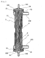
- Fig. 1 is a longitudinal sectional view showing a dialyzer useful for the understanding of the present invention before use.
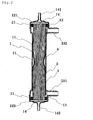
- Fig. 2 is a longitudinal sectional view showing the other example of a dialyzer.
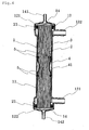
- Fig. 3 is a longitudinal sectional view showing a further dialyzer.
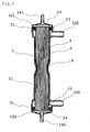
- Fig. 4 is a longitudinal sectional view showing an embodiment of the dialyzer of the present invention.
- Fig. 5 is a longitudinal sectional view showing another dialyzer.
- Fig. 6 is a longitudinal sectional view showing another dialyzer.
- Fig. 7 is a diagrammatic view of a method for manufacturing a dialyzer.
- Fig. 8 is a diagrammatic view of a method for manufacturing the dialyzer of the present invention.
- As shown in Fig. 1, the dialyzer is comprised of a nearly cylindrical case or
container 1 with both ends open, ahollow fiber bundle 3 made of a plurality ofhollow fiber membranes 2 and inserted into thecylindrical case 1 and a cylindrical heat-shrinkable tube 4 provided on an outside of thehollow fiber bundle 3 and at least a part of which can be shrunk by heating. - The
case 1 in the dialyzer has a nearlycylindrical case body 11 with both ends open and caps 121 and 122 mounted on both ends of thecase body 11. Thecase body 11 is further provided with adialyzate inlet 131 and adialyzate outlet 132. Thecap 121 is provided with ablood inlet 141 and thecap 122 is provided with ablood outlet 142. - The
case body 11 and thecaps case body 11 and thecaps blood inlet 141 and theblood outlet 142, thecaps - The
hollow fiber bundle 3 made of a plurality ofhollow fiber membranes 2 is accommodated in thecase 1. With respect to thehollow fiber membrane 2, a membrane made of a material relatively excellent in heat resistance, such as polysulfone, polyether sulfone, polyacrylonitrile, polyamide, polyethylene or polypropylene is preferably used. It is preferable that an ultrafiltration rate (UFR) of thehollow fiber membrane 2 is 20 mL/hr·m2·mmHg or more in order to surely remove unnecessary ingredients in a blood. - The
hollow fiber membranes 2 are accommodated in thecase 1 in a state of ahollow fiber bundle 3 obtained by bundling from 100 to 12,000 membranes. The effective membrane area of thehollow fiber membranes 2 in the dialyzer is preferably from 0.1 to 3.0 m2, more preferably from 0.1 to 2.5 m2. Further, the packing ratio of thehollow fiber membranes 2 in thecase 1 is preferably from 20 to 80%, more preferably from 40 to 60%. - The
hollow fiber bundle 3 is fixed in thecase 1 by injecting apotting agent 21 in the gap between the inner wall of thecase body 11 and thehollow fiber membranes 2 on both ends of thehollow fiber bundle 3 and curing it, without clogging the lumens of thehollow fiber membranes 2. As thepotting agent 21, polyurethane, silicone, epoxy resin or the like is preferably used. Thepotting agent 21 closes adialyzate flow path 13 to be described later on both ends of thehollow fiber membranes 2 in order to prevent the dialyzate passing through thedialyzate flow path 13 from flowing into theblood inlet 141 and theblood outlet 142 on both ends of thehollow fiber membranes 2. - In the dialyzer, the
hollow fiber bundle 3 is accommodated in thecase 1 to provide thedialyzate flow path 13 formed by the gap between the inner wall of thecase 1 and thehollow fiber membranes 2 and ablood flow path 14 formed by the lumens of the hollow fiber membranes. One end of thedialyzate flow path 13 communicates with thedialyzate inlet 131, and another end communicates with thedialyzate outlet 132. Further, one end of theblood flow path 14 communicates with theblood inlet 141, and another end communicates with theblood outlet 142. When the dialyzer is used, blood flows from theblood inlet 141 to theblood outlet 142 via theblood flow path 14, and the dialyzate flows from thedialyzate inlet 131 to thedialyzate outlet 132 via thedialyzate flow path 13. The dialysis can be performed at good efficiency by flowing the blood and the dialyzate in opposite directions through thehollow fiber membranes 2. - When a constricted portion is formed between the
dialyzate inlet 131 and thedialyzate outlet 132 on thecase body 11 of the dialyzer, the cross-sectional area of thedialyzate flow path 13 is decreased and a pressure loss along the dialyzate is increased. As a result, internal filtration and internal backfiltration are accelerated. Therefore, thecase body 11 in the dialyzer of the present invention may have a constricted portion unless the insertion of thehollow fiber bundle 3 into thecase 1 is hindered. - In the dialyzer, the cylindrical heat-
shrinkable tube 4 is mounted in the gap between the inner wall of thecase body 11 and the outer surface ofhollow fiber bundle 3. The heat-shrinkable tube 4 is formed of a material which is shrunk by heating, for example, a polyfluoroethylene-type fiber such as PTFE, FEP, TFE or PFA, polyethylene, polypropylene, polyester, vinyl chloride, synthetic rubber or silicone rubber. More preferably, thetube 4 is formed of a transparent or semitransparent material. The heat-shrinkable tube 4 of the present invention may be wholly formed of the foregoing material, or a portion to be shrunk may be formed of the foregoing material and other portions may be formed of anon-heat-shrinkablematerial such as polycarbonate or acrylic resin. - The heat-
shrinkable tube 4 may be combined in thecase 1 as shown in Fig. 1, or may be fixed to the inner wall of thecase 1 as shown in Fig. 2. In the dialyzer in which the heat-shrinkable tube 4 is combined in thecase 1 shown in Fig. 1, a part of thecase body 11 may be formed of the heat-shrinkable tube 4 or the whole of thecase body 11 may be formed of the heat-shrinkable tube 4. With respect to the dialyzer in which a part of thecase body 11 is formed of the heat-shrinkable tube 4, thecase body 11 is formed by insert molding, ultrasonic fusion or solvent bonding. - In the dialyzer in which the heat-
shrinkable tube 4 is fixed to the inner wall of thecase 1, an outer diameter of the heat-shrinkable tube 4 before being shrunk is preferably of such a size that thetube 4 is easily inserted into thecase 1 and water-tightly contacted with the inner wall of thecase body 11. Further, an inner diameter of the heat-shrinkable tube 4 before being shrunk is cf such a size that a packing ratio of thehollow fiber bundle 3 in a portion in which thetube 4 is inserted in thecase body 11 is preferably from 30 to 60%, more preferably from 40 to 50%. A thickness of the heat-shrinkable tube 4 is properly determined according to its material and is preferably from 0.1 to 2 mm, more preferably from 0.2 to 1.0 mm. Accordingly, it is possible with the dialyzer of the present invention to easily insert thehollow fiber bundle 3 into thecase 1. - A total length of the heat-
shrinkable tube 4 before being shrunk is properly changed within a length which is less than a length from thedialyzate inlet 131 to thedialyzate outlet 132 in thecase body 11. As shown in Fig. 2, when the heat-shrinkable tube 4 is short, the material cost is low and the heat-shrinking time of the dialyzer is short. Further, as shown in Fig. 3, when the heat-shrinkable tube 4 is long, the internal filtration and the internal backfiltration of a sufficient amount of fluid can be performed even when using a material having a low heat shrinkage percentage. - The heating of the heat-
shrinkable tube 4 is conducted preferably with a heating device made of brass or a drier, or by infrared irradiation, far-infrared irradiation or the like. The heat-shrinkable tube 4 preferably has a property of being shrunk by heating at from 40 to 120°C, more preferably from 40 to 100°C which does not influence or affect thehollow fiber membranes 2. - In the heat-
shrinkable tube 4 after being shrunk, the packing ratio of thehollow fiber bundle 3 in the shrunk portion of the heat-shrinkable tube 4 is from 70 to 90%, preferably from 75 to 80%. The shrinkage percentage of the heat-shrinkable tube 4 can be adjusted by changing the heating temperature, the material and a thickness. - The shrinking of the heat-
shrinkable tube 4 is conducted for the purpose of decreasing the cross-sectional area of thedialyzate flow path 13. In the dialyzer shown in Fig. 2, when the heat-shrinkable tube 4 is shrunk, aspace 41 is sometimes formed between the inner wall of thecase body 11 and the heat-shrinkable tube 4. When thespace 41 communicates with thedialyzate flow path 13, the dialyzate passing through thedialyzate flow path 13 flows into thespace 41. Thus, the original purpose of decreasing the cross-sectional area of thedialyzate flow path 13 is not attained. Accordingly, in order to prevent the dialyzate from flowing into thespace 41, it is preferred that the central portion of the heat-shrinkable tube 4 is locally heated and shrunk as shown in Fig. 2. The heated central portion of the heat-shrinkable tube 4 shrinks to decrease the cross-sectional area of thedialyzate flow path 13, while the unheated ends of the heat-shrinkable tube 4 do not shrink, which makes it possible to prevent the dialyzate passing through thedialyzate flow path 13 from entering thespace 41. - When the heating of the heat-
shrinkable tube 4 is conducted not locally but wholly, it is preferable that both ends of the heat-shrinkable tube 4 are fixed on the inner wall of thecase body 11 as shown in Fig. 2. As shown in Fig.4, according to the present invention rings 5 mounted inside both ends of the heat-shrinkable tube 4 to liquid-tightly fix both ends of thetube 4 on the inner wall of thecase body 11 are provided so as not to communicate thespace 41 with thedialyzate flow path 13. An outer diameter of thering 5 is such a size that thering 5 is liquid-tightly contacted with the inner wall of the heat-shrinkable tube 4. Further, thering 5 preferably has such an inner diameter that the packing ratio of thehollow fiber bundle 3 in the portion in which thering 5 is inserted is from 45 to 55%. When thering 5 has an inner diameter that causes the packing ratio to be less than 45%, thering 5 becomes a barrier when inserting thehollow fiber bundle 3 into thecase 1, which may cause thehollow fiber membranes 2 to rupture. - The
ring 5 is preferably made of a non-heat-shrinkable material such as polycarbonate or acrylic resin for enabling both ends of the heat-shrinkable tube 4 to be securely fixed on the inner wall of thecase body 11. - The dialyzer in which the heat-
shrinkable tube 4 is fixed to the inner wall of thecase 1 shown in Fig. 2 may be one in which a part of thecase body 11 which is close to the heat-shrinkable tube 4 is made of a heat-deformable material and is deformed to abut on the heat-shrinkable tube 4, as shown in Fig. 5, for eliminating thespace 41 between the inner wall of thecase body 11 and the heat-shrinkable tube 4. The whole of thecase body 11 may be made of a heat-deformable material, for example, a thermoplastic material such as polycarbonate or polystyrene, or only a part close to the heat-shrinkable tube 4 in thecase body 11 may be made of such a material. - The
case body 11 may be deformed in a shape according to the shape of the heat-shrinkable tube 4 for eliminating thespace 41 by heating with a heating device made of brass, or heating by infrared irradiation and using a device made of brass as with the heat-shrinkable tube 4. - When the dialyzer of the present invention has the structure shown in Fig. 4, the cross-sectional area of the
dialyzate flow path 13 can be decreased by conducting the heating of the heat-shrinkable tube 4 not only locally but also wholly. - Further, another example of a dialyzer is shown in Fig. 6, in which a filler is introduced into the
space 41 between the inner wall of thecase body 11 and the heat-shrinkable tube 4. Thefillerisintroducedfrom, for example,afillerinjection port 6 formed on thecase body 11. As the filler, polyurethane, urethane foam, flowable heat-curing resin such as epoxy resin, a room temperature-curing silicon filler (RTV) or the like is preferably used. - A method for manufacturing a dialyzer in which a part of the
case body 11 is formed of the heat-shrinkable tube 4 as shown in Fig. 1 is illustrated in Fig. 7. The method for manufacturing the dialyzer as illustrated in Fig. 7 comprises the following steps (1) and (2). - (1) The
hollow fiber bundle 3 is inserted in the lumen of thecase body 11, a part of which is formed of the heat-shrinkable tube 4 (a). - (2) A
potting agent 21 is injected into both ends of thecase body 11 in which thehollow fiber bundle 3 is inserted and obtained in the step (1) (b) to fix thehollow fiber bundle 3 within thecase body 11, and at least a part of the heat-shrinkable tube 4 is then shrunk by heating (c). - After the steps (1) and (2), the
caps case body 11 to complete the manufacture of the dialyzer. - A method for manufacturing the dialyzer in which the heat-
shrinkable tube 4 is fixed on the inner wall of thecase 1 as shown in Fig. 5 is illustrated in Fig. 8. The method for manufacturing the dialyzer as illustrated in Fig. 8 comprises the following steps (1) to (3). - (1) First, the heat-
shrinkable tube 4 which is not shrunk is inserted in the vicinity of the central portion of the case body 11 (a). - (2) Subsequently to the step (1), the
hollow fiber bundle 3 is inserted into the lumen of the heat-shrinkable tube 4 within the case body 11 (b). - (3) A
potting agent 21 is injected into both ends of thecase body 11 obtained in step (2) in which the heat-shrinkable tube 4 and thehollow fiber bundle 3 are inserted (c) to fix thehollow fiber bundle 3 within thecase body 11, and at least a part of the heat-shrinkable tube 4 is then shrunk by heating (d). - In the example shown in Fig. 8, the part of the
case body 11 which is close to the heat-shrinkable tube 4 is also heated simultaneously, and deformed to abut on the heat-shrinkable tube 4. After the steps (1) to (3), thecaps case body 11 to complete the manufacture of the dialyzer. - In a conventional method for manufacturing a dialyzer using a cylindrical product having a property of being swelled with a dialyzate, a hollow fiber bundle is inserted into a lumen of the product which has a far smaller inner diameter than an inner diameter of a case, and the product is then inserted into the case along with the hollow fiber bundle. The insertion of the hollow fiber bundle into the lumen of the product in such a dialyzer is quite difficult, and there is also a likelihood of rupturing the hollow fiber membranes. However, in the method for manufacturing the dialyzer in the present invention, the heat-
shrinkable tube 4 having a large inner diameter and which is not shrunk is previously inserted into thecase body 11. Accordingly, the insertion of the heat-shrinkable tube 4 into thecase body 11 is easy and the insertion of thehollow fiber bundle 3 into thecase 1 is conducted without difficulty by using a conventional device as such. - Fig. 9 is a graph showing pressure distribution of a fluid in the
blood flow path 14 and thedialyzate flow path 13 in the dialyzer when the blood and the dialyzate flow in the dialyzer of the present invention. - The internal filtration and the internal backfiltration of the dialyzer occur by a difference between the pressure of the blood in the
blood flow path 14 and the pressure of the dialyzate in the dialyzate flow path 13 (transmembrane pressure difference TMP). As shown by a line of the pressure of the blood and a line of the pressure of thedialyzate 1 in the graph , the internal filtration occurs in the vicinity of the blood inlet 141 (left side in the graph) because the pressure of the blood in theblood flow path 14 is higher than the pressure of the dialyzate of thedialyzate flow path 13. Internal backfiltration occurs in the vicinity of the blood outlet 142 (right side in the graph) because the pressure of the blood in theblood flow path 14 is lower than the pressure of the dialyzate in thedialyzate flow path 13. As TMP is greater, the internal filtration and the internal backfiltration of a large amoun of fluid occur. The difference between the internal backfiltration rate and the internal filtration rate (internal backfiltration rate minus internal filtration rate) corresponds to a dewatering rate. The dewatering rate is controlled for each patient who undergoes dialysis by a dewatering rate controller incorporated in a general equipment for dialysis. - In the dialyzer of the present invention, the heat-
shrinkable tube 4 is used for increasing TMP. When the heat-shrinkable tube 4 is shrunk by heating, the cross-sectional area of thedialyzate flow path 13 is decreased as shown in Figs. 1 to 6. As a result of the decrease in the cross-sectional area of thedialyzate flow path 13, the pressure of the dialyzate is abruptly increasedat the portion inwhich the heat-shrinkable tube 4 is inserted as shown by the line of the pressure of thedialyzate 2 in the graph. As a result, TMP is increased to allow the internal filtration and the internal backfiltration of a large amount of fluid. - Examples that specifically illustrate the invention and other dialyzes are described below.
- A tube made of polytetrafluoroethylene (hereinafter abbreviated as PTFE) and having a total length of 60 mm and an outer diameter of 36 mm was inserted into a central portion of a case body of a dialyzer made of polycarbonate and having a total length of 272 mm and an inner diameter of 36.5 mm. Subsequently, a hollow fiber bundle obtained by bundling approximately 9,000 hollow fiber membranes each made of polyether sulfone and having an inner diameter of 200 µm and an outer diameter of 260 µm was inserted into the lumen of the tube. A potting agent was injected into both ends of the case body to fix the hollow fiber bundle in the case body. An effective membrane area of the hollow fiber bundle was 1.5 m2, and a packing ratio of the hollow fiber bundle was 45%. Then, the case body in the dialyzer was heated at 100°C with a heater from an outer surface of the case body to locally heat and shrink the central portion of the PTFE tube, and caps were then mounted on both ends of the case body to manufacture a dialyzer. In the dialyzer, an inner diameter of the shrunk portion of the heat-shrinkable tube was 28.5 mm, a length of the shrunk portion of the heat-shrinkable tube was 40 mm, and the packing ratio of the hollow fiber bundle in the shrunk portion was 77%.
- A PTFE tube having a total length of 60 mm and an outer diameter of 36 mm was inserted into a central portion of a case body of a dialyzer made of polycarbonate and having a total length of 272 mm and an inner diameter of 36.5 mm. Further, rings each made of polycarbonate and having an outer diameter of 35.5 mm at a distal end and an outer diameter of 36.5 mm at a proximal end were inserted into both ends of the lumen of the tube to fix the tube in the case body. Subsequently, a hollow fiber bundle obtained by bundling approximately 9,000 hollow fiber membranes each made of polyether sulfone and having an inner diameter of 200 µm and an outer diameter of 260 µm was inserted into the lumen of the tube. A potting agent was injected into both ends of the case body to fix the hollow fiber bundle in the case body. An effective membrane area of the hollow fiber bundle was 1.5 m2, and a packing ratio of the hollow fiber bundle was 45%. Then, the case body in the dialyzer was heated at 100°C with a heater from an outer surface of the case body to locally heat and shrink the central portion of the PTFE tube. Moreover, the case body was deformed to abut on the tube by being heated with a heater, and caps were then mounted on both ends of the case body to manufacture a dialyzer. In the dialyzer, an inner diameter of the shrunk portion of the heat-shrinkable tube was 28.5 mm, a length of the shrunk portion of the heat-shrinkable tube was 40 mm, and the packing ratio of the hollow fiber bundle in the shrunk portion was 77%.
- A PTFE tube having a total length of 60 mm and an outer diameter of 36 mm was inserted into a central portion of a case body of a dialyzer made of polycarbonate and having a total length of 272 mm and an inner diameter of 36.5 mm. Subsequently, a hollow fiber bundle obtained by bundling approximately 9, 000 hollow fiber membranes each made of polyether sulfone and having an inner diameter of 200 µm and an outer diameter of 260 µm was inserted into the lumen of the tube. A potting agent was injected into both ends of the case body to fix the hollow fiber bundle in the case body. An effective membrane area of the hollow fiber bundle was 1.5 m2, and a packing ratio of the hollow fiber bundle was 45%. Then, the case body in the dialyzer was heated at 100°C with a heater from an outer surface of the case body to locally heat and shrink the central portion of the PTFE tube. Moreover, the case body was deformed to abut on the tube by being heated with a heater, and caps were then mounted on both ends of the case body to manufacture a dialyzer. In the dialyzer, an inner diameter of the shrunk portion of the heat-shrinkable tube was 28.5 mm, a length of the shrunk portion of the heat-shrinkable tube was 60 mm, and the packing ratio of the hollow fiber bundle in the shrunk portion was 77%.
- A PTFE tube having a total length of 60 mm and an outer diameter of 36 mm was inserted into a central portion of a case body of a dialyzer made of polycarbonate and having a total length of 272 mm and an inner diameter of 36.5 mm. Subsequently, a hollow fiber bundle obtained by bundling approximately 9,000 hollow fiber membranes each made of polyether sulfone and having an inner diameter of 200 µm and an outer diameter of 260 µm was inserted into the lumen of the tube. A potting agent was injected into both ends of the case body to fix the hollow fiber bundle in the case body. An effective membrane area of the hollow fiber bundle was 1.5 m2, and a packing ratio of the hollow fiber bundle was 45%. Then, the case body in the dialyzer was heated at 100°C with a heater from an outer surface of the case body to locally heat and shrink the central portion of the PTFE tube. Moreover, urethane foam was charged into a space between the inner wall of the case body and the PTFE tube, and caps were then mounted on both ends of the case body to manufacture a dialyzer. In the dialyzer, an inner diameter of the shrunk portion of the heat-shrinkable tube was 28.5 mm, a length of the shrunk portion of the heat-shrinkable tube was 55 mm, and the packing ratio of the hollow fiber bundle in the shrunk portion was 77%.
- A hollow fiber bundle obtained by bundling approximately 9,000 hollow fiber membranes each made of polyether sulfone and having an inner diameter of 200 µm and an outer diameter of 260 µm was inserted into a lumen of a case body of a dialyzer made of polycarbonate and having a total length of 272 mm and an inner diameter of 36.5 mm. A potting agent was injected into both ends of the case body to fix the hollow fiber bundle in the case body. An effective membrane area of the hollow fiber bundle was 1.5 m2, and a packing ratio of the hollow fiber bundle was 45%. Caps were then mounted on both ends of the case body to manufacture a dialyzer.
- A dialyzate was passed through the dialyzate flow path of the dialyzer obtained in each of Examples 1 to 4 and Comparative Example 1 at a flow rate of 500 mL/min, and a pressure loss of the dialyzate was measured by measuring pressures of the dialyzate at the dialyzate inlet and the dialyzate outlet. The results are shown in Table 1.
- Further, a dialysis experiment of myoglobin (molecular weight 17,000) was conducted using the dialyzer obtained in each of Examples 1 to 4 and Comparative Example 1 to measure a clearance. The flow rate conditions in the measurement are that a blood flow rate is 200 mL/min, a dialyzate flow rate is 500 mL/min and a dewatering rate is 0 mL/min. The results are shown in Table 1.
Table 1 Pressure loss [mmHg] Clearance (mL/min] Example 1 70 78 Example 2 90 80 Example 3 120 82 Example 4 110 81 Comparative Example 1 15 72 - As shown in Table 1, it is found that the pressure loss of the dialyzate in the dialyzer of the present invention in Examples 1 to 4 is significantly increased in comparison to the pressure loss of the dialyzate in the conventional dialyzer in Comparative Example 1. It is further found that the clearance of myoglobin in the dialyzer of the present invention in Examples 1 to 4 is increased in comparison to the clearance in the conventional dialyzer in Comparative Example 1.
- The results reveal that the dialyzer of the present invention which is provided with the heat-shrinkable tube is, in comparison to the conventional dialyzer not having the heat-shrinkable tube, decreased in the cross-sectional area of the dialyzate flow path to thereby clearly increase the internal filtration rate and the internal backfiltration rate.
- The dialyzer of the present invention can increase the flux of internal filtration and the flux of internal backfiltration by providing a cylindrical heat-shrinkable tube at least a part of which is shrunk by heating. Further, since the sectional area of the dialyzate flow path is sufficiently decreased by shrinking the heat-shrinkable tube through heating, the flux of internal filtration and the flux of internal backfiltration can easily be increased. Moreover, in the method for manufacturing the dialyzer of the present invention, the heat-shrinkable tube is previously inserted in the case of the dialyzer and the hollow fiber bundle is then inserted. Accordingly, the dialyzer can easily be manufactured without using a special device and without fear of rupturing the hollow fiber membranes.
Claims (5)
- A dialyzer comprising a substantially cylindrical case (1), a hollow fiber bundle (3) made of a plurality of hollow fiber membranes (2) provided in said case (1), a blood flow path (14) formed by lumens of the hollow fiber membranes (2), a dialyzate flow path (13) formed by a gap between an inner wall of the case (1) and the hollow fiber membranes (2) and a cylindrical heat-shrinkable tube (4) provided on an outside of the hollow fiber bundle (3) and liquid-tightly fixed to the inner wall of the case (1) at both ends of the tube (4) with rings (5) inserted in the lumen of the heat-shrinkable tube (4), wherein at least a part of said heat-shrinkable tube (4) can be shrunk by heating.
- The dialyzer according to claim 1, wherein a central portion of the heat-shrinkable tube (4) can be shrunk by heating.
- The dialyzer according to claim 1 or claim 2, wherein at least a part of the case (1) close to the heat-shrinkable tube (4) is formed of a heat-deformable material and can be deformed together with the heat-shrinkable tube (4).
- The dialyzer according to any one of claims 1-3, wherein the case (1) has a filler injection port (6) to introduce a filler into a space between the inner wall of the case (1) and the heat-shrinkable tube (4) after shrinking.
- A method for manufacturing a dialyzer, comprising the following steps (a) to (c),(a) inserting a cylindrical heat-shrinkable tube (4) into a substantially cylindrical case (1) and liquid-tightly fixing both ends of the tube (4) to the inner wall of the case (1) with rings (5) inserted in the lumen of the heat-shrinkable tube (4),(b) subsequently, inserting a hollow fiber bundle (3) made of a plurality of hollow fiber membranes (2) into a lumen of the heat-shrinkable tube (4) in the case (1), and(c) subsequent to step (b), heating at least a part of the heat-shrinkable tube (4) in the case (1) to shrink the tube.
Applications Claiming Priority (2)
| Application Number | Priority Date | Filing Date | Title |
|---|---|---|---|
| JP2002069870 | 2002-03-14 | ||
| JP2002069870 | 2002-03-14 |
Publications (2)
| Publication Number | Publication Date |
|---|---|
| EP1344542A1 EP1344542A1 (en) | 2003-09-17 |
| EP1344542B1 true EP1344542B1 (en) | 2007-05-16 |
Family
ID=27764530
Family Applications (1)
| Application Number | Title | Priority Date | Filing Date |
|---|---|---|---|
| EP03005393A Expired - Lifetime EP1344542B1 (en) | 2002-03-14 | 2003-03-13 | Dialyzer and method for manufacturing the same |
Country Status (3)
| Country | Link |
|---|---|
| US (1) | US7094348B2 (en) |
| EP (1) | EP1344542B1 (en) |
| DE (1) | DE60313818T2 (en) |
Cited By (2)
| Publication number | Priority date | Publication date | Assignee | Title |
|---|---|---|---|---|
| US7744553B2 (en) | 2003-12-16 | 2010-06-29 | Baxter International Inc. | Medical fluid therapy flow control systems and methods |
| DE202017101271U1 (en) | 2017-03-06 | 2018-06-07 | DÖRRE textiles, papers and films e.K. | Banderole for forming a tubular casing as a handling aid, such a tubular casing and a filter unit with handling aid |
Families Citing this family (19)
| Publication number | Priority date | Publication date | Assignee | Title |
|---|---|---|---|---|
| DE60331403D1 (en) * | 2002-12-26 | 2010-04-08 | Nipro Corp | Dialyzer and its production process |
| CA2481865C (en) * | 2003-09-24 | 2011-07-05 | Nipro Corporation | Hollow fiber blood-processing device and method for packaging and sterilizing such devices |
| CA2484096A1 (en) * | 2004-10-07 | 2006-04-07 | Zenon Environmental Inc. | Method of locating and repairing damaged hollow fibers within membrane modules and header assembly |
| DE102007009208B4 (en) * | 2007-02-26 | 2010-01-28 | Fresenius Medical Care Deutschland Gmbh | Hollow fiber, hollow fiber bundles, filters and processes for producing a hollow fiber or a hollow fiber bundle |
| JP4939280B2 (en) * | 2007-03-30 | 2012-05-23 | 本田技研工業株式会社 | Humidifier |
| KR101250056B1 (en) * | 2008-06-04 | 2013-04-03 | 아사히 가세이 케미칼즈 가부시키가이샤 | Hollow fiber membrane module with covered membrane outer periphery |
| TWI469992B (en) * | 2008-08-28 | 2015-01-21 | Baxter Int | Methods of concentrating shear-sensitive biopolymers |
| US9370324B2 (en) * | 2008-11-05 | 2016-06-21 | Fresenius Medical Care Holdings, Inc. | Hemodialysis patient data acquisition, management and analysis system |
| US8743354B2 (en) | 2010-09-07 | 2014-06-03 | Fresenius Medical Care Holdings, Inc. | Shrouded sensor clip assembly and blood chamber for an optical blood monitoring system |
| US9194792B2 (en) | 2010-09-07 | 2015-11-24 | Fresenius Medical Care Holdings, Inc. | Blood chamber for an optical blood monitoring system |
| JP6059150B2 (en) | 2010-11-17 | 2017-01-11 | フレセニウス メディカル ケア ホールディングス インコーポレーテッド | Sensor clip assembly for optical monitoring systems |
| US9173988B2 (en) | 2010-11-17 | 2015-11-03 | Fresenius Medical Care Holdings, Inc. | Sensor clip assembly for an optical monitoring system |
| USD725261S1 (en) | 2012-02-24 | 2015-03-24 | Fresenius Medical Care Holdings, Inc. | Blood flow chamber |
| US20140202950A1 (en) * | 2013-01-23 | 2014-07-24 | Asian Institute Of Technology | Anodized aluminum oxide tubular nano-porous membrane module and method of manufacture thereof |
| DE102014108230A1 (en) | 2014-06-12 | 2015-12-17 | B. Braun Avitum Ag | Dialyzer with a bundle of hollow fibers and method for producing such a hollow fiber |
| CN107249664B (en) | 2015-02-24 | 2020-11-10 | 泰尔茂株式会社 | Method for manufacturing hollow fiber type blood treatment device, and hollow fiber type blood treatment device |
| USD799031S1 (en) | 2015-09-09 | 2017-10-03 | Fresenius Medical Care Holdings, Inc. | Blood flow chamber with directional arrow |
| DE102016117599A1 (en) * | 2016-09-19 | 2018-03-22 | B. Braun Avitum Ag | Sterile containers with a sterile barrier separate from a primary packaging, as well as methods for producing a sterile package |
| DE102017101307A1 (en) * | 2017-01-24 | 2018-07-26 | B. Braun Avitum Ag | Dialyzer with improved internal filtration and process for its preparation |
Family Cites Families (11)
| Publication number | Priority date | Publication date | Assignee | Title |
|---|---|---|---|---|
| FR2267138A1 (en) * | 1974-04-09 | 1975-11-07 | Rhone Poulenc Ind | Hollow fibre bundle for fluid treatment - partic. useful for dialysis or ultrafiltration |
| US4219426A (en) * | 1976-03-19 | 1980-08-26 | Organon Teknika B.V. | Dialysis device |
| JP2961481B2 (en) | 1993-08-30 | 1999-10-12 | サイテック株式会社 | Hemodialyzer and hemofilter |
| JP3284028B2 (en) | 1994-09-02 | 2002-05-20 | テルモ株式会社 | Dialysis machine |
| ES2142981T3 (en) * | 1994-09-02 | 2000-05-01 | Terumo Corp | DIALIZER. |
| JPH08168525A (en) | 1994-12-19 | 1996-07-02 | Terumo Corp | Production of hollow fiber membrane type blood treating device and production apparatus therefor |
| WO1998022161A1 (en) | 1996-11-15 | 1998-05-28 | Scitec K.K. | Hollow fiber dialyzer |
| JPH11394A (en) * | 1997-06-13 | 1999-01-06 | Terumo Corp | Hollow yarn film type dialytic filter and dialytic filtration device |
| JPH119684A (en) * | 1997-06-25 | 1999-01-19 | Terumo Corp | Hollow fiber membrane type blood dialysis filter, constricted part forming member device jig and hollow fiber membrane bundle inserting jig as well as production of hollow fiber membrane blood dialysis filter |
| JPH11319080A (en) | 1998-05-12 | 1999-11-24 | Nikkiso Co Ltd | Hollow fiber type hemodialyzer |
| JPH11319079A (en) * | 1998-05-12 | 1999-11-24 | Nikkiso Co Ltd | Hollow fiber type hemodialyzer |
-
2003
- 2003-03-13 DE DE60313818T patent/DE60313818T2/en not_active Expired - Lifetime
- 2003-03-13 EP EP03005393A patent/EP1344542B1/en not_active Expired - Lifetime
- 2003-03-14 US US10/387,493 patent/US7094348B2/en not_active Expired - Fee Related
Non-Patent Citations (1)
| Title |
|---|
| None * |
Cited By (4)
| Publication number | Priority date | Publication date | Assignee | Title |
|---|---|---|---|---|
| US7744553B2 (en) | 2003-12-16 | 2010-06-29 | Baxter International Inc. | Medical fluid therapy flow control systems and methods |
| US8430835B2 (en) | 2003-12-16 | 2013-04-30 | Baxter International Inc. | Renal therapy blood cleansing system with balance chamber and bolus, rinseback or prime volume feature |
| US9211370B2 (en) | 2003-12-16 | 2015-12-15 | Baxter International Inc. | Renal therapy blood cleansing system with isolation feature |
| DE202017101271U1 (en) | 2017-03-06 | 2018-06-07 | DÖRRE textiles, papers and films e.K. | Banderole for forming a tubular casing as a handling aid, such a tubular casing and a filter unit with handling aid |
Also Published As
| Publication number | Publication date |
|---|---|
| EP1344542A1 (en) | 2003-09-17 |
| US20030196949A1 (en) | 2003-10-23 |
| US7094348B2 (en) | 2006-08-22 |
| DE60313818T2 (en) | 2007-10-31 |
| DE60313818D1 (en) | 2007-06-28 |
Similar Documents
| Publication | Publication Date | Title |
|---|---|---|
| EP1344542B1 (en) | Dialyzer and method for manufacturing the same | |
| EP1433490B1 (en) | Dialyzer and method for manufacturing the same | |
| US5730712A (en) | Extracorporeal blood treatment apparatus and method | |
| CA2427252C (en) | Dual-stage filtration cartridge | |
| US4231871A (en) | Artificial kidney and method for making same | |
| JP4173969B2 (en) | Hemodialysis filter and hemodiafiltration device | |
| US20090229466A1 (en) | Blood treatment dialyzer/filter for permitting gas removal | |
| GB1602060A (en) | Artificial kidney and method for making same | |
| JPH01223973A (en) | Blood dialyzing cartridge, apparatus and method | |
| JP3284028B2 (en) | Dialysis machine | |
| EP1398047B1 (en) | End-cap for a dialyser, dialyser and method for removing gas bubbles | |
| JP2000210539A (en) | Body fluid treatment device, hollow fiber membrane assembly and production of body fluid treatment device | |
| JP4144844B2 (en) | Hollow fiber membrane dialysis filter | |
| JP4144843B2 (en) | Hollow fiber membrane dialysis filter | |
| JP2004216143A (en) | Dialyzer and its manufacturing method | |
| JP4807912B2 (en) | Hollow fiber membrane module and manufacturing method thereof | |
| JP4168761B2 (en) | Dialysis machine and manufacturing method thereof | |
| JP3821557B2 (en) | Blood purifier manufacturing method | |
| JP4245597B2 (en) | Blood purifier | |
| JP7224104B2 (en) | Dialysis device with improved internal filtration and method of manufacture | |
| JP3257999B2 (en) | Hollow fiber membrane dialyzer | |
| US20090236027A1 (en) | Blood Treatment Filter and Method of Manufacturing | |
| CN100518836C (en) | Diafiltration method | |
| WO2006070890A1 (en) | Hollow fibter type apparatus for blood purification | |
| JP2000070359A (en) | Hollow fiber membrane type dialyser |
Legal Events
| Date | Code | Title | Description |
|---|---|---|---|
| PUAI | Public reference made under article 153(3) epc to a published international application that has entered the european phase |
Free format text: ORIGINAL CODE: 0009012 |
|
| AK | Designated contracting states |
Kind code of ref document: A1 Designated state(s): AT BE BG CH CY CZ DE DK EE ES FI FR GB GR HU IE IT LI LU MC NL PT RO SE SI SK TR |
|
| AX | Request for extension of the european patent |
Extension state: AL LT LV MK RO |
|
| 17P | Request for examination filed |
Effective date: 20040223 |
|
| AKX | Designation fees paid |
Designated state(s): DE FR GB IT |
|
| GRAP | Despatch of communication of intention to grant a patent |
Free format text: ORIGINAL CODE: EPIDOSNIGR1 |
|
| GRAS | Grant fee paid |
Free format text: ORIGINAL CODE: EPIDOSNIGR3 |
|
| GRAA | (expected) grant |
Free format text: ORIGINAL CODE: 0009210 |
|
| AK | Designated contracting states |
Kind code of ref document: B1 Designated state(s): DE FR GB IT |
|
| REG | Reference to a national code |
Ref country code: GB Ref legal event code: FG4D |
|
| REF | Corresponds to: |
Ref document number: 60313818 Country of ref document: DE Date of ref document: 20070628 Kind code of ref document: P |
|
| ET | Fr: translation filed | ||
| PLBE | No opposition filed within time limit |
Free format text: ORIGINAL CODE: 0009261 |
|
| STAA | Information on the status of an ep patent application or granted ep patent |
Free format text: STATUS: NO OPPOSITION FILED WITHIN TIME LIMIT |
|
| 26N | No opposition filed |
Effective date: 20080219 |
|
| REG | Reference to a national code |
Ref country code: FR Ref legal event code: PLFP Year of fee payment: 13 |
|
| REG | Reference to a national code |
Ref country code: FR Ref legal event code: PLFP Year of fee payment: 14 |
|
| REG | Reference to a national code |
Ref country code: FR Ref legal event code: PLFP Year of fee payment: 15 |
|
| REG | Reference to a national code |
Ref country code: FR Ref legal event code: PLFP Year of fee payment: 16 |
|
| PGFP | Annual fee paid to national office [announced via postgrant information from national office to epo] |
Ref country code: GB Payment date: 20220321 Year of fee payment: 20 Ref country code: DE Payment date: 20220322 Year of fee payment: 20 |
|
| PGFP | Annual fee paid to national office [announced via postgrant information from national office to epo] |
Ref country code: IT Payment date: 20220322 Year of fee payment: 20 Ref country code: FR Payment date: 20220322 Year of fee payment: 20 |
|
| REG | Reference to a national code |
Ref country code: DE Ref legal event code: R071 Ref document number: 60313818 Country of ref document: DE |
|
| REG | Reference to a national code |
Ref country code: GB Ref legal event code: PE20 Expiry date: 20230312 |
|
| PG25 | Lapsed in a contracting state [announced via postgrant information from national office to epo] |
Ref country code: GB Free format text: LAPSE BECAUSE OF EXPIRATION OF PROTECTION Effective date: 20230312 |