EP1347296A2 - Storage cartridge for biosensors - Google Patents
Storage cartridge for biosensors Download PDFInfo
- Publication number
- EP1347296A2 EP1347296A2 EP03004827A EP03004827A EP1347296A2 EP 1347296 A2 EP1347296 A2 EP 1347296A2 EP 03004827 A EP03004827 A EP 03004827A EP 03004827 A EP03004827 A EP 03004827A EP 1347296 A2 EP1347296 A2 EP 1347296A2
- Authority
- EP
- European Patent Office
- Prior art keywords
- biosensors
- open top
- conveying member
- storage cartridge
- stack
- Prior art date
- Legal status (The legal status is an assumption and is not a legal conclusion. Google has not performed a legal analysis and makes no representation as to the accuracy of the status listed.)
- Granted
Links
- 239000012491 analyte Substances 0.000 claims abstract description 6
- 210000001124 body fluid Anatomy 0.000 claims abstract description 6
- 239000010839 body fluid Substances 0.000 claims abstract description 6
- 238000000034 method Methods 0.000 claims description 6
- 229920000098 polyolefin Polymers 0.000 claims description 3
- 230000005540 biological transmission Effects 0.000 claims description 2
- 238000012360 testing method Methods 0.000 description 45
- 239000008280 blood Substances 0.000 description 32
- 210000004369 blood Anatomy 0.000 description 32
- WQZGKKKJIJFFOK-GASJEMHNSA-N Glucose Natural products OC[C@H]1OC(O)[C@H](O)[C@@H](O)[C@@H]1O WQZGKKKJIJFFOK-GASJEMHNSA-N 0.000 description 23
- 239000008103 glucose Substances 0.000 description 23
- 239000000463 material Substances 0.000 description 11
- 239000002274 desiccant Substances 0.000 description 10
- 239000011888 foil Substances 0.000 description 6
- 238000012544 monitoring process Methods 0.000 description 5
- 238000012986 modification Methods 0.000 description 4
- 230000004048 modification Effects 0.000 description 4
- 230000009471 action Effects 0.000 description 3
- 238000006243 chemical reaction Methods 0.000 description 3
- 239000003153 chemical reaction reagent Substances 0.000 description 3
- 208000013016 Hypoglycemia Diseases 0.000 description 2
- 239000011324 bead Substances 0.000 description 2
- 238000003306 harvesting Methods 0.000 description 2
- 201000001421 hyperglycemia Diseases 0.000 description 2
- 230000002218 hypoglycaemic effect Effects 0.000 description 2
- 230000001788 irregular Effects 0.000 description 2
- 230000007246 mechanism Effects 0.000 description 2
- 230000003287 optical effect Effects 0.000 description 2
- 230000003647 oxidation Effects 0.000 description 2
- 238000007254 oxidation reaction Methods 0.000 description 2
- 230000008569 process Effects 0.000 description 2
- 241000251468 Actinopterygii Species 0.000 description 1
- 230000002411 adverse Effects 0.000 description 1
- XAGFODPZIPBFFR-UHFFFAOYSA-N aluminium Chemical compound [Al] XAGFODPZIPBFFR-UHFFFAOYSA-N 0.000 description 1
- 229910052782 aluminium Inorganic materials 0.000 description 1
- 210000003323 beak Anatomy 0.000 description 1
- 238000004891 communication Methods 0.000 description 1
- 238000012864 cross contamination Methods 0.000 description 1
- 230000003247 decreasing effect Effects 0.000 description 1
- 230000001419 dependent effect Effects 0.000 description 1
- 206010012601 diabetes mellitus Diseases 0.000 description 1
- 238000003487 electrochemical reaction Methods 0.000 description 1
- 238000005516 engineering process Methods 0.000 description 1
- 239000012530 fluid Substances 0.000 description 1
- 239000012943 hotmelt Substances 0.000 description 1
- 230000001771 impaired effect Effects 0.000 description 1
- 239000002650 laminated plastic Substances 0.000 description 1
- 230000013011 mating Effects 0.000 description 1
- 239000002808 molecular sieve Substances 0.000 description 1
- 238000004806 packaging method and process Methods 0.000 description 1
- 239000008188 pellet Substances 0.000 description 1
- 239000000843 powder Substances 0.000 description 1
- 230000001737 promoting effect Effects 0.000 description 1
- URGAHOPLAPQHLN-UHFFFAOYSA-N sodium aluminosilicate Chemical compound [Na+].[Al+3].[O-][Si]([O-])=O.[O-][Si]([O-])=O URGAHOPLAPQHLN-UHFFFAOYSA-N 0.000 description 1
Images


Classifications
-
- G—PHYSICS
- G01—MEASURING; TESTING
- G01N—INVESTIGATING OR ANALYSING MATERIALS BY DETERMINING THEIR CHEMICAL OR PHYSICAL PROPERTIES
- G01N33/00—Investigating or analysing materials by specific methods not covered by groups G01N1/00 - G01N31/00
- G01N33/48—Biological material, e.g. blood, urine; Haemocytometers
- G01N33/483—Physical analysis of biological material
- G01N33/487—Physical analysis of biological material of liquid biological material
- G01N33/4875—Details of handling test elements, e.g. dispensing or storage, not specific to a particular test method
- G01N33/48757—Test elements dispensed from a stack
Definitions
- the present invention relates generally to blood glucose monitoring systems for determining the concentration of glucose in blood, and more particularly, to a storage cartridge for dispensing biosensors for use with blood glucose monitoring systems.
- a sample of blood It is often necessary to quickly obtain a sample of blood and perform an analysis of the blood sample.
- One example of a need for obtaining a sample of blood is in connection with a blood glucose monitoring system, which a user must frequently use to monitor the user's blood glucose level.
- Those who have irregular blood glucose concentration levels are medically required to regularly self-monitor their blood glucose concentration level.
- An irregular blood glucose level can be brought on by a variety of reasons including illness such as diabetes.
- the purpose of monitoring the blood glucose concentration level is to determine the blood glucose concentration level and then to take corrective action, based upon whether the level is too high or too low, to bring the level back within a normal range.
- the failure to take corrective action can have serious implications.
- blood glucose levels drop too low - known as hypoglycemia -
- a person can become nervous, shaky and confused. That person's judgment may become impaired and that person may eventually pass out.
- a person can also become very ill if their blood glucose level becomes too high - a condition known as hyperglycemia. Both conditions, hypoglycemia and hyperglycemia, are potentially life-threatening emergencies.
- the glucose testing device includes a biosensor to harvest the blood for analysis.
- One type of biosensor is the electrochemical biosensor.
- the electrochemical biosensor includes a regent designed to react with glucose in the blood to create an oxidation current at electrodes disposed within the electrochemical biosensor which is directly promotional to the users blood glucose concentration.
- Such a biosensor is described in U.S. Patent Nos. 5,120,420, 5,660,791, 5,759,364 and 5,798,031, each of which is incorporated herein in its entirety.
- Another type of sensor is an optical biosensor, which incorporates a reagent designed to produce a colorimetric reaction indicative of a user's blood glucose concentration level. The colorimetric reaction is then read by a spectrometer incorporated into the testing device.
- a spectrometer incorporated into the testing device.
- a drop of blood is obtained from the person's fingertip using a lancing device, and the blood is harvested using the biosensor.
- the biosensor which is inserted into a testing unit, is brought into contact with the blood drop.
- the biosensor draws the blood, via capillary action, inside the biosensor and the ensuing electrochemical reaction is measured by the test unit which then determines the concentration of glucose in the blood.
- the biosensor is discarded. Each new test requires a new biosensor.
- the sensor pack 30 is designed to be housed within the testing device 10.
- a collection area 14 of an individual biosensor 12 Prior to each test, a collection area 14 of an individual biosensor 12 is pushed by a mechanism within the testing device 10 through its packaging and is extended from the testing device 10 through a slot 16 for harvesting a sample of blood.
- the testing device 10 includes a slider 18 for advancing the test tensor 12.
- a biosensor 12 is shown extending from the testing device 10.
- the collection area 14 extends from the testing device 10, while a contact area, disposed at the opposite end of the biosensor 12 shown in FIGS. 1 and 2, remains inside the testing device 10.
- the contact area includes terminals that electrically couple the electrodes to a meter disposed within the testing device 10 for measuring the oxidation current produced at the electrodes by the reaction of glucose and the reagent.
- the test unit includes a display 20.
- biosensors 12 are shown disposed in the sensor pack 30.
- the sensor pack 30 is made up of a circular disk 32 having ten individual compartments (blisters) 34 arranged radially.
- the disk is made from an aluminum foil/plastic laminate which is sealed to isolate the sensor from ambient humidity and from other sensors with a burst foil cover 36.
- Each biosensor 12 is kept dry by a desiccant located inside a desiccant compartment 37 disposed adjacent to the compartment 34.
- a mechanism disposed within the testing device 10 such as a knife, is driven down through the burst foil into an individual elongated compartment 34 at the end closest to the hub of the disk 32 and then moved radially toward the perimeter of the blister 34. In doing so, the knife engages the contact area 38 (fish tail) of the sensor in that compartment. Radial travel of the knife pushes the tip of the sensor out through the burst foil 36 and through parts of the testing device 10 such that the collection area 14 of the sensor 12 is completely out of the testing device 10 and ready to receive a fluid test sample such as blood. For this stage, it is essential that the bond between the base and lid of the sensor withstand the sheer forces generated when the sensor bursts out through the foil 36. This method of providing a sensor ready for use is more fully described in U.S. Patent No. 5,575,403, which is incorporated herein by reference in its entirety.
- a drawback associated with this flat array of testing devices is the large area that is occupied.
- the size of testing devices that internally house such a flat array package constrains the size of the package (i.e., the number of sensors), thus making it difficult to increase the number of sensors per package. Accordingly, there exists a need for a testing system wherein the biosensor package size is independent of the testing device.
- a storage cartridge for dispensing biosensors used in the determination of an analyte in body fluid comprises a hollow body for housing a stack of biosensors having an open top, a flexible conveying member disposed over the open top of the body, the flexible conveying member having an aperture formed therein for receiving a biosensor from the stack of biosensors, a plate adapted to press the sliding conveying member against the open top to form a substantially moisture-impervious seal around the open top of the body and to permit the conveying member to slide between the plate and the open top, and means for biasing the stack of biosensors towards the open top
- FIG. 3 there is shown a sensor cartridge 100 for storing a plurality of biosensors 102, such as the biosensors 12 described in connection with FIGS. 1 and 2, according to one embodiment of the present invention.
- a testing device 104 which receives a biosensor 102 from the sensor cartridge 100 for determining a person's blood glucose level.
- the testing device 104 functions similar to that of the prior art testing device 10 shown in FIG. 1.
- the storage cartridge 100 provides a sealed, substantially moisture-impervious environment for storing the plurality of biosensors 102.
- the plurality of biosensors 102 are stacked, substantially one on top of the next, as shown in FIGS. 3-6.
- the biosensors 102 are dispensed from the storage cartridge 100 via a sealed outlet 106.
- the stacked biosensors 102 are in vapor communication with a desiccant material 108 disposed within the storage cartridge 100.
- the desiccant material 108 maintains the interior of the sensor cartridge 100 at an appropriate humidity level so that the reagent material disposed within the biosensors 102 is not adversely affected prior to being used.
- the desiccant material 108 is in the form of a small bag, round bead of material, a hot melt, a molded shape or any other form that can be readily disposed in the sensor cartridge 100. While the desiccant material 108 shown (FIG. 3) is disposed towards the bottom of the storage cartridge 102, the desiccant material 108 may be disposed anywhere practical within the storage cartridge 100 according to alternative embodiments of the storage cartridge 100.
- the amount of such desiccant material 108 placed within the sensor cartridge 100 will be dependent on the amount that is required to maintain the interior of the sensor cartridge 100 in a desiccated state.
- One type of commercially available desiccant material that can be used in one embodiment of the present invention is 13X synthetic molecular sieves from Multisorb Technologies Inc. of Buffalo, New York, available in powder, pellet and bead forms.
- the sensor cartridge 100 is made of a rigid, moisture-impervious material such as plastic. Each of the biosensors are approximately 0.50 inch long (about 12.70 mm), approximately 0.03 inch thick (about 0.76 mm) and approximately 0.20 inch wide (about 5.08 mm). The interior of the of the sensor cartridge 100 is dimensioned only slightly larger than the length and width of the biosensors 120 to allow the biosensors 102 to move vertically within the storage cartridge (as described below) but not side-to-side (as viewed in FIG. 3) so that the stack of the biosensors 102 is maintained.
- the storage cartridge 100 has an interior width W of approximately 0.52 inch (about 13.21 mm) and an interior depth (into the page as viewed in FIG. 3) of approximately 0.22 inch (about 5.59 mm).
- the interior height H is approximately 2.25 inch (about 57.15 mm) for an embodiment of the storage cartridge that is adapted to houses approximately fifty sensors.
- the interior height H can be varied according to alternative embodiments of the storage cartridge 100 to accommodate an increased or decreased number of biosensor 102.
- the sensors 102 are dispensed from the storage cartridge 100 via the sealed outlet 106 located towards the top 110 of the storage cartridge.
- the stack of biosensors 102 is biased upward towards the top 110 of the storage cartridge 100 by a resilient member such as a spring 112 disposed between the stack of biosensors 102 and an interior bottom surface 114 of the storage cartridge 100.
- the top of the storage cartridge 100 is sealed by a flexible, slideable conveying member 116 that is pressed against the top 110 of the storage cartridge 100 by a top plate 134.
- the conveying member 116 is made out of polyolefin, which includes the attributes of low moisture vapor transmission, flexibility and a lubricious surface.
- the conveying member 116 protrudes from the storage cartridge 100 at the outlet 106 as well as through a second outlet 118 located on the opposite side of the storage cartridge 100.
- the conveying member 116 seals outlets 106, 118 as described below.
- the conveying member 116 (FIG. 7) includes a cutout or nest 120.
- the nest 120 is designed to fit around a biosensor 102.
- the nest 102 receives the biosensor 102.
- the conveying member 116 which surrounds a biosensor 102, is pulled across the top of the storage cartridge 100 (from right to left as viewed in FIG. 3) and, in turn, the biosensor 102 is pulled/dragged from the storage cartridge 100.
- the nest 120 is cut in the shape of a biosensor such as the biosensors 12 depicted in FIG. 2.
- the nest 120 is more general in shape (e.g., a rectangle) to accommodate biosensors of a variety of shapes.
- the user of the storage cartridge 100 and testing device 104 pulls a first end 122 of the conveying member 116.
- the spring 112 which constantly biases the stack of biosensors 102 upward, pushes the biosensor 102 at the top of the stack into the nest 120.
- This biosensor 102 within the nest 120 and surrounded by the conveying member 116, is pulled along with the conveying member 116 towards the outlet 106.
- the flexible conveying member 116 is pulled around a post 124 at an approximately 90° angle.
- the post 124 is shown disposed away from the storage cartridge 100.
- the post 124 is an integral component of the storage cartridge 100 as is shown in FIG 6.
- the post 124 may comprise a rounded corner of the storage cartridge 100.
- the conveying member 116 is pulled in the direction indicated by arrow A from the storage cartridge 100 such that the biosensor 102 is partially protruding from the outlet 106 of the storage cartridge 100.
- the relatively rigid biosensor 102 continues to travel in a straight line (in the direction of arrow A).
- a trailing end 132 of the biosensor 102 which is still within the storage cartridge 100, is still constrained to its original path by the top plate 134 of the storage cartridge 100 and the adjacent lower biosensor 102.
- the conveying member 116 is pulled in the direction indicated by arrow A until a substantial portion of the leading end 130 of the biosensor 102 is extended beyond the post 124 and is not surrounded by the conveying member 116.
- the leading end 130 of the biosensor 102 is then forced into a mating portion 140 of the testing device 104.
- the spring 112 forces a biosensor 102 within the storage cartridge upward against the conveying member 116.
- the biosensor 102 is now disposed within the testing device and can be used in the analysis of a sample of blood.
- the second end 142 of the conveying member 116 is pulled back in the direction indicated by arrow B causing the nest 120 to be brought back inside the storage cartridge 100 to receive another biosensor 102 for the next test.
- the conveying member 116 is pulled back into the test cartridge 100 and the nest 120 passes over the stack of biosensors 102, the uppermost biosensor 102 is forced upward into the nest 120 by the spring 112.
- the post has 124 been shown as not attached to the storage cartridge 100.
- the post 124 is shown as a rounded corner of protrusion 125 which extends outward from the cartridge 100.
- FIG. 8a there is shown a cut-away view of the storage cartridge 100 along dashed line 8 (FIG. 6).
- the conveying member 116 is disposed between side-walls 150 of the storage cartridge 100 and the top plate 134.
- the plate 134 functions as the top of the storage cartridge 100.
- the plate 134 is pressed down onto the conveying member 116 with sufficient pressure that a substantially moisture-impervious seal is formed between the top plate 134, the sliding conveying member 116 and the walls 150 of the storage cartridge.
- the pressed thickness of the conveying member 116 is at least slightly less than that of the biosensor 102 to facilitate the trapping and dragging of just one biosensor out of the storage cartridge.
- a substantially constant amount of pressure is applied by the plate 134 to the conveying member 116 and the walls 150.
- a suitable fastener e.g., screws, rivets, clamps
- the constant pressure applied to the conveying member 116 by the plate 134 should not be so great as to unduly inhibit the sliding of conveying member 116 when pulled by a user when dispensing of a biosensor 102.
- Constructing the conveying member 116 out of a lubricious material such as polyolefin facilitates the sliding movement of the conveying member 116.
- the pressure applied to the conveying member 116 and walls 150 by the plate 134 may be temporarily reduced or eliminated during the during the dragging process.
- the reduced pressure may break the substantially moisture-impervious seal of the storage cassette 100.
- any moisture leaking into the storage cassette 100 during the temporary beak in the seal is absorbed by the desiccant 108 (FIG. 3).
- a variety of mechanical schemes can be employed for varying the pressure applied by the top plate 134 according to alternative embodiments of the present invention.
- an adjustable clamp (not shown) may be used to vary the pressure applied by the top plate 134.
- screws such screws having heads large enough to be grasped by a user's fingers, may be used to vary the pressure applied by the top plate 134.
- an elastic member (not shown) may apply sufficient pressure to the top plate 134 for forming the seal around the walls 150, but be elastic enough to allow the plate to lift slightly during the dragging process when a biosensor is being dispensed.
- a wedge-type of arrangement can be employed wherein the top plate 134 is inserted into grooves (not shown) disposed within the interior of walls 150 wherein the grooves direct the top plate 134 down into pressed contact with the conveying member 116.
- the conveying member 116 is disposed on flat surfaces 154 which are integrally formed in walls 150.
- the conveying member 116 is disposed directly on top of walls 150 according to the alternative embodiment of the storage cartridge 100 shown in FIG. 8b.
- the biosensors 102 are arranged within the storage cartridge such that the.leading end 130 of the biosensor 102 (i.e., the end of the first pulled from the cartridge 100) is the contact area of an electrochemical biosensor.
- the contact area of the biosensor 102 includes terminals which electrically couple the biosensor 102 to the testing device 104. Dispensing the biosensors 102 in this manner is advantageous over many prior art biosensor dispensing schemes because the sample collection area ( i.e. , disposed on the end opposite the contact area in FIGS. 1 and 2) of the biosensor 102 never contacts or passes through the testing device 104. This arrangement removes the potential risk of cross-contamination in situations where the testing device 104 may be used by more than one patient.
- the storage cartridge is part of the testing device.
- the portion of the testing device that receives the sensor is movable with respect to the storage cartridge such that the sample collection area of the sensor is available to receive the sample.
- the second end 142 of the conveying member 116 has been shown and described as extending out of the storage cartridge through the second outlet 118.
- the second end 142 of the conveying member 118 remains within the storage cartridge 100.
- the second end is attached to a resilient member within the storage cartridge 100 for retracting the sliding conveying member 116 after a biosensor 102 has been dispensed.
- the conveying member 116 is pushed back through the first outlet 106 by the user.
- a mechanical apparatus such as a roller is integrated into the storage cartridge 100 for pushing or pulling the conveying member 116 back into the storage cartridge 100.
- the storage cartridge 100 implements a length of conveying member 116 having a plurality of evenly spaced-apart nests 120 formed therein.
- the length of conveying member 116 is stored in the form of a roll, or is folded. After a portion of the conveying member 116 is pulled from the cartridge 100 and a sensor 102 is dispensed, that portion of the conveying member 116 can be torn or cut and discarded leaving a sufficient amount of conveying member to grasp for dispensing the next cartridge.
- biasing members are used in place of a resilient member (e.g. the spring 112 shown in FIG. 3) for upwardly (as view in FIG. 3) the stack of biosensors 102.
- the biasing member may include a first magnet disposed on the interior bottom surface 114 of the storage cartridge 100 and a second repulsively disposed magnet attached to the stack of biosensors 102.
- the stack of sensors 102 is biased upward via electromagnetic forces that cause the first magnet and the second magnet to repulse ( i.e. , push away from) each other.
- the magnets comprise opposing ferromagnets as opposed to eletromagnets.
- a combination of electomagnets and ferromagnets may be used.
- the biasing member may comprise a pneumatic system wherein a compressed gas is used to upwardly bias the stack of biosensors 102.
- the stack of biosensors 102 are disposed on the top-side of a piston in a piston-cylinder arrangement, wherein the cartridge 100 severs as the cylinder. A compressed gas disposed in the cylinder, beneath the piston, biases the stack of test sensors 102 towards the top 110 of the cartridge 100.
Abstract
Description
- The present invention relates generally to blood glucose monitoring systems for determining the concentration of glucose in blood, and more particularly, to a storage cartridge for dispensing biosensors for use with blood glucose monitoring systems.
- It is often necessary to quickly obtain a sample of blood and perform an analysis of the blood sample. One example of a need for obtaining a sample of blood is in connection with a blood glucose monitoring system, which a user must frequently use to monitor the user's blood glucose level.
- Those who have irregular blood glucose concentration levels are medically required to regularly self-monitor their blood glucose concentration level. An irregular blood glucose level can be brought on by a variety of reasons including illness such as diabetes. The purpose of monitoring the blood glucose concentration level is to determine the blood glucose concentration level and then to take corrective action, based upon whether the level is too high or too low, to bring the level back within a normal range. The failure to take corrective action can have serious implications. When blood glucose levels drop too low - a condition known as hypoglycemia - a person can become nervous, shaky and confused. That person's judgment may become impaired and that person may eventually pass out. A person can also become very ill if their blood glucose level becomes too high - a condition known as hyperglycemia. Both conditions, hypoglycemia and hyperglycemia, are potentially life-threatening emergencies.
- One method of monitoring a person's blood glucose level is with a portable, hand-held blood glucose testing device. The portable nature of these devices enables the users to conveniently test their blood glucose levels wherever the user may be. The glucose testing device includes a biosensor to harvest the blood for analysis. One type of biosensor is the electrochemical biosensor. The electrochemical biosensor includes a regent designed to react with glucose in the blood to create an oxidation current at electrodes disposed within the electrochemical biosensor which is directly promotional to the users blood glucose concentration. Such a biosensor is described in U.S. Patent Nos. 5,120,420, 5,660,791, 5,759,364 and 5,798,031, each of which is incorporated herein in its entirety. Another type of sensor is an optical biosensor, which incorporates a reagent designed to produce a colorimetric reaction indicative of a user's blood glucose concentration level. The colorimetric reaction is then read by a spectrometer incorporated into the testing device. Such an optical biosensor is described in U.S. Patent No. 5,194,393, which is incorporated herein by reference in its entirety.
- In order to check a person's blood glucose level, a drop of blood is obtained from the person's fingertip using a lancing device, and the blood is harvested using the biosensor. The biosensor, which is inserted into a testing unit, is brought into contact with the blood drop. The biosensor draws the blood, via capillary action, inside the biosensor and the ensuing electrochemical reaction is measured by the test unit which then determines the concentration of glucose in the blood. Once the results of the test are displayed on a display of the test unit, the biosensor is discarded. Each new test requires a new biosensor.
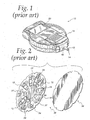
- Referring now to FIGS. 1 and 2, an example of a
testing device 10 and apackage 30 of biosensors 12 ("sensor pack") are shown, respectively. Thesensor pack 30 is designed to be housed within thetesting device 10. Prior to each test, acollection area 14 of anindividual biosensor 12 is pushed by a mechanism within thetesting device 10 through its packaging and is extended from thetesting device 10 through aslot 16 for harvesting a sample of blood. Thetesting device 10 includes aslider 18 for advancing thetest tensor 12. In FIG. 1, abiosensor 12 is shown extending from thetesting device 10. Thecollection area 14 extends from thetesting device 10, while a contact area, disposed at the opposite end of thebiosensor 12 shown in FIGS. 1 and 2, remains inside thetesting device 10. The contact area includes terminals that electrically couple the electrodes to a meter disposed within thetesting device 10 for measuring the oxidation current produced at the electrodes by the reaction of glucose and the reagent. The test unit includes adisplay 20. - Referring now to FIG. 2,
biosensors 12 are shown disposed in thesensor pack 30. Thesensor pack 30 is made up of acircular disk 32 having ten individual compartments (blisters) 34 arranged radially. The disk is made from an aluminum foil/plastic laminate which is sealed to isolate the sensor from ambient humidity and from other sensors with aburst foil cover 36. Eachbiosensor 12 is kept dry by a desiccant located inside adesiccant compartment 37 disposed adjacent to thecompartment 34. - To retrieve a sensor, a mechanism disposed within the
testing device 10, such as a knife, is driven down through the burst foil into an individualelongated compartment 34 at the end closest to the hub of thedisk 32 and then moved radially toward the perimeter of theblister 34. In doing so, the knife engages the contact area 38 (fish tail) of the sensor in that compartment. Radial travel of the knife pushes the tip of the sensor out through theburst foil 36 and through parts of thetesting device 10 such that thecollection area 14 of thesensor 12 is completely out of thetesting device 10 and ready to receive a fluid test sample such as blood. For this stage, it is essential that the bond between the base and lid of the sensor withstand the sheer forces generated when the sensor bursts out through thefoil 36. This method of providing a sensor ready for use is more fully described in U.S. Patent No. 5,575,403, which is incorporated herein by reference in its entirety. - Further details of the operational and mechanical aspects of the
testing device 10 andsensor pack 30 are more fully described in U.S. Patent Nos. 5,575,403, 5,630,986, 5,738,244, 5,810,199, 5,854,074 and 5,856,195, each of which are hereby incorporated by reference in their entireties. - A drawback associated with this flat array of testing devices is the large area that is occupied. The size of testing devices that internally house such a flat array package constrains the size of the package (i.e., the number of sensors), thus making it difficult to increase the number of sensors per package. Accordingly, there exists a need for a testing system wherein the biosensor package size is independent of the testing device.
- A storage cartridge for dispensing biosensors used in the determination of an analyte in body fluid comprises a hollow body for housing a stack of biosensors having an open top, a flexible conveying member disposed over the open top of the body, the flexible conveying member having an aperture formed therein for receiving a biosensor from the stack of biosensors, a plate adapted to press the sliding conveying member against the open top to form a substantially moisture-impervious seal around the open top of the body and to permit the conveying member to slide between the plate and the open top, and means for biasing the stack of biosensors towards the open top
- The above summary of the present invention is not intended to represent each embodiment, or every aspect, of the present invention. Additional features and benefits of the present invention will become apparent from the detailed description, figures, and claims set forth below.
-
- FIG. 1 is a perspective view of a prior art testing device;
- FIG. 2 is a perspective view of a prior art sensor pack having a foil lid removed;
- FIG. 3 is a first side view of a storage cartridge for biosensors according to one embodiment of the present invention;
- FIG. 4 is a second side view of a storage cartridge for biosensors according to one embodiment of the present invention;
- FIG. 5 is a third side view of a storage cartridge for biosensors according to one embodiment of the present invention;
- FIG. 6 is fourth side view of a storage cartridge for biosensors according to one embodiment of the present invention;
- FIG. 7 is a perspective view of a flexible sliding conveying member for the storage cartridge for biosensors shown in FIGS. 3-6;
- FIG. 8a is a cut-away view of the storage cartridge shown in FIG. 6 along
dashed
line 8; and - FIG. 8b is a cut-away view along dashed
line 8 of FIG. 6 of an alternative embodiment of the storage cartridge. -
- While the invention is susceptible to various modifications and alternative forms, specific embodiments will be shown by way of example in the drawings and will be desired in detail herein. It should be understood, however, that the invention is not intended to be limited to the particular forms disclosed. Rather, the invention is to cover all modifications, equivalents and alternatives falling within the spirit and scope of the invention as defined by the appended claims.
- Referring now to FIG. 3, there is shown a
sensor cartridge 100 for storing a plurality ofbiosensors 102, such as thebiosensors 12 described in connection with FIGS. 1 and 2, according to one embodiment of the present invention. Also shown in FIG. 3 is atesting device 104 which receives abiosensor 102 from thesensor cartridge 100 for determining a person's blood glucose level. Thetesting device 104 functions similar to that of the priorart testing device 10 shown in FIG. 1. Thestorage cartridge 100 provides a sealed, substantially moisture-impervious environment for storing the plurality ofbiosensors 102. According to one embodiment of thestorage cartridge 100, the plurality ofbiosensors 102 are stacked, substantially one on top of the next, as shown in FIGS. 3-6. Generally, in use, thebiosensors 102 are dispensed from thestorage cartridge 100 via a sealedoutlet 106. - The
stacked biosensors 102 are in vapor communication with adesiccant material 108 disposed within thestorage cartridge 100. Thedesiccant material 108 maintains the interior of thesensor cartridge 100 at an appropriate humidity level so that the reagent material disposed within thebiosensors 102 is not adversely affected prior to being used. Thedesiccant material 108 is in the form of a small bag, round bead of material, a hot melt, a molded shape or any other form that can be readily disposed in thesensor cartridge 100. While thedesiccant material 108 shown (FIG. 3) is disposed towards the bottom of thestorage cartridge 102, thedesiccant material 108 may be disposed anywhere practical within thestorage cartridge 100 according to alternative embodiments of thestorage cartridge 100. The amount ofsuch desiccant material 108 placed within thesensor cartridge 100 will be dependent on the amount that is required to maintain the interior of thesensor cartridge 100 in a desiccated state. One type of commercially available desiccant material that can be used in one embodiment of the present invention is 13X synthetic molecular sieves from Multisorb Technologies Inc. of Buffalo, New York, available in powder, pellet and bead forms. - The
sensor cartridge 100 is made of a rigid, moisture-impervious material such as plastic. Each of the biosensors are approximately 0.50 inch long (about 12.70 mm), approximately 0.03 inch thick (about 0.76 mm) and approximately 0.20 inch wide (about 5.08 mm). The interior of the of thesensor cartridge 100 is dimensioned only slightly larger than the length and width of thebiosensors 120 to allow thebiosensors 102 to move vertically within the storage cartridge (as described below) but not side-to-side (as viewed in FIG. 3) so that the stack of thebiosensors 102 is maintained. For example, according to one embodiment of thestorage cartridge 100, thestorage cartridge 100 has an interior width W of approximately 0.52 inch (about 13.21 mm) and an interior depth (into the page as viewed in FIG. 3) of approximately 0.22 inch (about 5.59 mm). The interior height H is approximately 2.25 inch (about 57.15 mm) for an embodiment of the storage cartridge that is adapted to houses approximately fifty sensors. The interior height H can be varied according to alternative embodiments of thestorage cartridge 100 to accommodate an increased or decreased number ofbiosensor 102. - The
sensors 102 are dispensed from thestorage cartridge 100 via the sealedoutlet 106 located towards the top 110 of the storage cartridge. The stack ofbiosensors 102 is biased upward towards the top 110 of thestorage cartridge 100 by a resilient member such as a spring 112 disposed between the stack ofbiosensors 102 and aninterior bottom surface 114 of thestorage cartridge 100. - Referring now also to FIG. 4, the top of the
storage cartridge 100 is sealed by a flexible, slideable conveyingmember 116 that is pressed against the top 110 of thestorage cartridge 100 by atop plate 134. According to one embodiment, the conveyingmember 116 is made out of polyolefin, which includes the attributes of low moisture vapor transmission, flexibility and a lubricious surface. According to one embodiment, the conveyingmember 116 protrudes from thestorage cartridge 100 at theoutlet 106 as well as through asecond outlet 118 located on the opposite side of thestorage cartridge 100. The conveyingmember 116seals outlets nest 120. Thenest 120 is designed to fit around abiosensor 102. Put another way, thenest 102 receives thebiosensor 102. As described in further detail below, the conveyingmember 116, which surrounds abiosensor 102, is pulled across the top of the storage cartridge 100 (from right to left as viewed in FIG. 3) and, in turn, thebiosensor 102 is pulled/dragged from thestorage cartridge 100. As shown in FIG. 7, thenest 120 is cut in the shape of a biosensor such as thebiosensors 12 depicted in FIG. 2. In other embodiments, thenest 120 is more general in shape (e.g., a rectangle) to accommodate biosensors of a variety of shapes. - In operation, the user of the
storage cartridge 100 andtesting device 104 pulls afirst end 122 of the conveyingmember 116. Either prior to the user's pulling or during, the spring 112, which constantly biases the stack ofbiosensors 102 upward, pushes thebiosensor 102 at the top of the stack into thenest 120. Thisbiosensor 102, within thenest 120 and surrounded by the conveyingmember 116, is pulled along with the conveyingmember 116 towards theoutlet 106. The flexible conveyingmember 116 is pulled around apost 124 at an approximately 90° angle. In FIGS. 3-6, thepost 124 is shown disposed away from thestorage cartridge 100. However, in other embodiments, thepost 124 is an integral component of thestorage cartridge 100 as is shown in FIG 6. Alternatively still, thepost 124 may comprise a rounded corner of thestorage cartridge 100. - Referring now to FIG. 4, the conveying
member 116 is pulled in the direction indicated by arrow A from thestorage cartridge 100 such that thebiosensor 102 is partially protruding from theoutlet 106 of thestorage cartridge 100. Aleading end 130 of thebiosensor 102, surrounded by the conveyingmember 116, is proximate thepost 124. As the flexible conveyingmember 116 is pulled around thepost 124, the relativelyrigid biosensor 102 continues to travel in a straight line (in the direction of arrow A). A trailingend 132 of thebiosensor 102, which is still within thestorage cartridge 100, is still constrained to its original path by thetop plate 134 of thestorage cartridge 100 and the adjacentlower biosensor 102. - Referring now to FIG. 5, the conveying
member 116 is pulled in the direction indicated by arrow A until a substantial portion of theleading end 130 of thebiosensor 102 is extended beyond thepost 124 and is not surrounded by the conveyingmember 116. Theleading end 130 of thebiosensor 102 is then forced into amating portion 140 of thetesting device 104. As thebiosensor 102 is pulled out of the storage cartridge, the spring 112 forces abiosensor 102 within the storage cartridge upward against the conveyingmember 116. - Referring now also to FIG. 6, the
biosensor 102 is now disposed within the testing device and can be used in the analysis of a sample of blood. Thesecond end 142 of the conveyingmember 116 is pulled back in the direction indicated by arrow B causing thenest 120 to be brought back inside thestorage cartridge 100 to receive anotherbiosensor 102 for the next test. As the conveyingmember 116 is pulled back into thetest cartridge 100 and thenest 120 passes over the stack ofbiosensors 102, theuppermost biosensor 102 is forced upward into thenest 120 by the spring 112. - In FIGS. 3-5 the post has 124 been shown as not attached to the
storage cartridge 100. In FIG. 6, thepost 124 is shown as a rounded corner ofprotrusion 125 which extends outward from thecartridge 100. In other alternative embodiments of thestorage cassette 100, there is no protrusion 125 (or post 124) and the conveying member is simply pulled around the corner at theoutlet 106 of the storage cartridge. - Referring now to FIG. 8a there is shown a cut-away view of the
storage cartridge 100 along dashed line 8 (FIG. 6). The conveyingmember 116 is disposed between side-walls 150 of thestorage cartridge 100 and thetop plate 134. Theplate 134 functions as the top of thestorage cartridge 100. Theplate 134 is pressed down onto the conveyingmember 116 with sufficient pressure that a substantially moisture-impervious seal is formed between thetop plate 134, the sliding conveyingmember 116 and thewalls 150 of the storage cartridge. According to one embodiment, the pressed thickness of the conveyingmember 116 is at least slightly less than that of thebiosensor 102 to facilitate the trapping and dragging of just one biosensor out of the storage cartridge. According to one embodiment of the present invention, a substantially constant amount of pressure is applied by theplate 134 to the conveyingmember 116 and thewalls 150. A suitable fastener (e.g., screws, rivets, clamps) can be used to press theplate 134 against the conveyingmember 116 andwalls 150 as described. However, the constant pressure applied to the conveyingmember 116 by theplate 134 should not be so great as to unduly inhibit the sliding of conveyingmember 116 when pulled by a user when dispensing of abiosensor 102. Constructing the conveyingmember 116 out of a lubricious material such as polyolefin, according to one embodiment, facilitates the sliding movement of the conveyingmember 116. - In an alternative embodiment of the storage cassette 110, the pressure applied to the conveying
member 116 andwalls 150 by theplate 134 may be temporarily reduced or eliminated during the during the dragging process. In such an embodiment, the reduced pressure may break the substantially moisture-impervious seal of thestorage cassette 100. However, any moisture leaking into thestorage cassette 100 during the temporary beak in the seal is absorbed by the desiccant 108 (FIG. 3). A variety of mechanical schemes can be employed for varying the pressure applied by thetop plate 134 according to alternative embodiments of the present invention. For example, in one embodiment, an adjustable clamp (not shown) may be used to vary the pressure applied by thetop plate 134. In another embodiment, screws (not shown), such screws having heads large enough to be grasped by a user's fingers, may be used to vary the pressure applied by thetop plate 134. Alternatively still, an elastic member (not shown) may apply sufficient pressure to thetop plate 134 for forming the seal around thewalls 150, but be elastic enough to allow the plate to lift slightly during the dragging process when a biosensor is being dispensed. In yet another alternative embodiment, a wedge-type of arrangement can be employed wherein thetop plate 134 is inserted into grooves (not shown) disposed within the interior ofwalls 150 wherein the grooves direct thetop plate 134 down into pressed contact with the conveyingmember 116. - As shown in FIG. 8a, according to one embodiment, the conveying
member 116 is disposed onflat surfaces 154 which are integrally formed inwalls 150. However, other configurations are possible according to various other alternative embodiments of thestorage cassette 100. For example, the conveyingmember 116 is disposed directly on top ofwalls 150 according to the alternative embodiment of thestorage cartridge 100 shown in FIG. 8b. - According to one embodiment of the
storage cartridge 100, thebiosensors 102 are arranged within the storage cartridge such that the.leadingend 130 of the biosensor 102 (i.e., the end of the first pulled from the cartridge 100) is the contact area of an electrochemical biosensor. As discussed in the background section, the contact area of thebiosensor 102 includes terminals which electrically couple thebiosensor 102 to thetesting device 104. Dispensing thebiosensors 102 in this manner is advantageous over many prior art biosensor dispensing schemes because the sample collection area (i.e., disposed on the end opposite the contact area in FIGS. 1 and 2) of thebiosensor 102 never contacts or passes through thetesting device 104. This arrangement removes the potential risk of cross-contamination in situations where thetesting device 104 may be used by more than one patient. - According to still another alternative embodiment, the storage cartridge is part of the testing device. In such an embodiment, the portion of the testing device that receives the sensor is movable with respect to the storage cartridge such that the sample collection area of the sensor is available to receive the sample.
- Referring back to FIG. 6, the
second end 142 of the conveyingmember 116 has been shown and described as extending out of the storage cartridge through thesecond outlet 118. However, in alternative embodiments of the storage cartridge, thesecond end 142 of the conveyingmember 118 remains within thestorage cartridge 100. According to one such embodiment, the second end is attached to a resilient member within thestorage cartridge 100 for retracting the sliding conveyingmember 116 after abiosensor 102 has been dispensed. According to another such embodiment, the conveyingmember 116 is pushed back through thefirst outlet 106 by the user. According to yet another such embodiment, a mechanical apparatus such as a roller is integrated into thestorage cartridge 100 for pushing or pulling the conveyingmember 116 back into thestorage cartridge 100. - According to still another alternative embodiment of the
storage cartridge 100 implements a length of conveyingmember 116 having a plurality of evenly spaced-apartnests 120 formed therein. The length of conveyingmember 116 is stored in the form of a roll, or is folded. After a portion of the conveyingmember 116 is pulled from thecartridge 100 and asensor 102 is dispensed, that portion of the conveyingmember 116 can be torn or cut and discarded leaving a sufficient amount of conveying member to grasp for dispensing the next cartridge. - According to other alternative embodiments of the present invention, other biasing members are used in place of a resilient member (e.g. the spring 112 shown in FIG. 3) for upwardly (as view in FIG. 3) the stack of
biosensors 102. For example, in such alternative embodiments, the biasing member may include a first magnet disposed on theinterior bottom surface 114 of thestorage cartridge 100 and a second repulsively disposed magnet attached to the stack ofbiosensors 102. The stack ofsensors 102 is biased upward via electromagnetic forces that cause the first magnet and the second magnet to repulse (i.e., push away from) each other. In another alternative embodiment, the magnets comprise opposing ferromagnets as opposed to eletromagnets. Alternatively, a combination of electomagnets and ferromagnets may be used. - In other alternative embodiments, the biasing member may comprise a pneumatic system wherein a compressed gas is used to upwardly bias the stack of
biosensors 102. According to one alternative embodiment, the stack ofbiosensors 102 are disposed on the top-side of a piston in a piston-cylinder arrangement, wherein thecartridge 100 severs as the cylinder. A compressed gas disposed in the cylinder, beneath the piston, biases the stack oftest sensors 102 towards the top 110 of thecartridge 100. - While the invention is susceptible to various modifications and alternative forms, specific embodiments thereof have been shown by way of example in the drawings and herein described in detail. It should be understood, however, that it is not intended to limit the invention to the particular forms disclosed, but on the contrary, the intention is to cover all modifications, equivalents, and alternatives falling within the spirit and scope of the invention as defined by the appended claims.
Claims (10)
- A storage cartridge for dispensing biosensors used in the determination of an analyte in body fluid, the storage cartridge comprising:a hollow body for housing a stack of biosensors having an open top;a flexible conveying member disposed over the open top of the body, the flexible conveying member having an aperture formed therein for receiving a biosensor from the stack of biosensors;a plate adapted to press the sliding conveying member against the open top in a manner to form a substantially moisture-impervious seal around the open top of the body and to permit the conveying member to slide between the plate and the open top; anda biasing member for biasing the stack of biosensors towards the open top of the body.
- The storage cartridge of claim 1 wherein the flexible conveying member is made out of polyolefin.
- The storage cartridge of claim 1 wherein the flexible conveying member has a lubricious surface.
- The storage cartridge of claim 1 wherein the flexible conveying member has a low moisture vapor transmission rate.
- The storage cartridge of claim 1 wherein the biasing member comprises a resilient member disposed between the stack of biosensors and an interior bottom surface of the hollow body.
- The storage cartridge of claim 5 wherein the resilient member is a spring.
- The storage cartridge of claim 1 wherein the biasing member includes a compressed gas disposed between the stack of and an interior bottom surface of the hollow body.
- A method for dispensing a biosensor used in the determination of an analyte in body fluid from a biosensor storage cartridge, the method comprising:stacking a plurality of biosensors within a hollow body of the storage cartridge, the cartridge being closed at a bottom end and open at a top end;disposing a conveying tape over the open top end, the conveying tape having at least one aperture disposed therein for receiving a biosensor;applying a pressure to the conveying tape for pressing the conveying tape against the open top end to form a substantially moisture-impervious seal over the open top end;biasing the biosensors stacked within the cartridge towards the sealed top end of the cartridge;receiving a biosensor from the stack of biosensors in the at least one aperture formed in the conveying tape; andpulling a portion of the conveying tape from the cartridge such that the biosensor received in the at least one aperture is pulled from the cartridge.
- A storage cartridge for dispensing biosensors used in the determination of an analyte in body fluid, the storage cartridge comprising:a hollow body for housing a stack of biosensors having an open top;a flexible conveying member disposed over the open top of the body, the flexible conveying member having an aperture formed therein for receiving a biosensor from the stack of biosensors;a plate disposed on the open top of the body, the plate adapted to move to between a first position and a second position, the plate adapted to press the conveying member against the open top to form a substantially moisture impervious seal in the first position, the plate adapted to permit the conveying member to slide between the plate and the open top in the second position; anda biasing member for urging the stack of biosensors towards the open top.
- A storage cartridge for dispensing biosensors used in the determination of an analyte in body fluid, the storage cartridge comprising:a hollow body for housing a stack of biosensors having an open top;a flexible conveying member disposed over the open top of the body, the flexible conveying member having an aperture formed therein for receiving a biosensor from the stack of biosensors;a plate adapted to press the sliding conveying member against the open top to form a substantially moisture-impervious seal around the open top of the body and to permit the conveying member to slide between the plate and the open top; andmeans for biasing the stack of biosensors towards the open top.
Applications Claiming Priority (2)
| Application Number | Priority Date | Filing Date | Title |
|---|---|---|---|
| US36484802P | 2002-03-18 | 2002-03-18 | |
| US364848P | 2002-03-18 |
Publications (3)
| Publication Number | Publication Date |
|---|---|
| EP1347296A2 true EP1347296A2 (en) | 2003-09-24 |
| EP1347296A3 EP1347296A3 (en) | 2005-02-09 |
| EP1347296B1 EP1347296B1 (en) | 2008-07-09 |
Family
ID=27789163
Family Applications (1)
| Application Number | Title | Priority Date | Filing Date |
|---|---|---|---|
| EP03004827A Expired - Lifetime EP1347296B1 (en) | 2002-03-18 | 2003-03-05 | Storage cartridge for biosensors |
Country Status (9)
| Country | Link |
|---|---|
| US (3) | US7270247B2 (en) |
| EP (1) | EP1347296B1 (en) |
| JP (1) | JP4316905B2 (en) |
| AT (1) | ATE400811T1 (en) |
| AU (1) | AU2003200811B2 (en) |
| CA (1) | CA2419905C (en) |
| DE (1) | DE60321984D1 (en) |
| DK (1) | DK1347296T3 (en) |
| ES (1) | ES2307841T3 (en) |
Cited By (5)
| Publication number | Priority date | Publication date | Assignee | Title |
|---|---|---|---|---|
| WO2006002432A1 (en) * | 2004-06-24 | 2006-01-05 | Bayer Healthcare Llc | Cartridge and sensor-dispensing instrument |
| WO2006009534A1 (en) * | 2004-06-18 | 2006-01-26 | Roche Diagnostics Gmbh | Dispenser for flattened articles such as diagnostic test strips |
| US7582262B2 (en) | 2004-06-18 | 2009-09-01 | Roche Diagnostics Operations, Inc. | Dispenser for flattened articles |
| US7585464B2 (en) | 2002-04-19 | 2009-09-08 | Panasonic Corporation | Biosensor cartridge and biosensor dispensing device |
| CN111137537A (en) * | 2020-01-06 | 2020-05-12 | 盖霞 | Specimen sample is preserved and is used low temperature storage device |
Families Citing this family (92)
| Publication number | Priority date | Publication date | Assignee | Title |
|---|---|---|---|---|
| US6391005B1 (en) | 1998-03-30 | 2002-05-21 | Agilent Technologies, Inc. | Apparatus and method for penetration with shaft having a sensor for sensing penetration depth |
| US8641644B2 (en) | 2000-11-21 | 2014-02-04 | Sanofi-Aventis Deutschland Gmbh | Blood testing apparatus having a rotatable cartridge with multiple lancing elements and testing means |
| US7749174B2 (en) | 2001-06-12 | 2010-07-06 | Pelikan Technologies, Inc. | Method and apparatus for lancet launching device intergrated onto a blood-sampling cartridge |
| US7041068B2 (en) | 2001-06-12 | 2006-05-09 | Pelikan Technologies, Inc. | Sampling module device and method |
| US7033371B2 (en) | 2001-06-12 | 2006-04-25 | Pelikan Technologies, Inc. | Electric lancet actuator |
| US9427532B2 (en) | 2001-06-12 | 2016-08-30 | Sanofi-Aventis Deutschland Gmbh | Tissue penetration device |
| CA2448902C (en) | 2001-06-12 | 2010-09-07 | Pelikan Technologies, Inc. | Self optimizing lancing device with adaptation means to temporal variations in cutaneous properties |
| US9226699B2 (en) | 2002-04-19 | 2016-01-05 | Sanofi-Aventis Deutschland Gmbh | Body fluid sampling module with a continuous compression tissue interface surface |
| US7981056B2 (en) | 2002-04-19 | 2011-07-19 | Pelikan Technologies, Inc. | Methods and apparatus for lancet actuation |
| US8337419B2 (en) | 2002-04-19 | 2012-12-25 | Sanofi-Aventis Deutschland Gmbh | Tissue penetration device |
| US7344507B2 (en) | 2002-04-19 | 2008-03-18 | Pelikan Technologies, Inc. | Method and apparatus for lancet actuation |
| US9795747B2 (en) | 2010-06-02 | 2017-10-24 | Sanofi-Aventis Deutschland Gmbh | Methods and apparatus for lancet actuation |
| US7226461B2 (en) | 2002-04-19 | 2007-06-05 | Pelikan Technologies, Inc. | Method and apparatus for a multi-use body fluid sampling device with sterility barrier release |
| US9795334B2 (en) | 2002-04-19 | 2017-10-24 | Sanofi-Aventis Deutschland Gmbh | Method and apparatus for penetrating tissue |
| US8579831B2 (en) | 2002-04-19 | 2013-11-12 | Sanofi-Aventis Deutschland Gmbh | Method and apparatus for penetrating tissue |
| US7892183B2 (en) | 2002-04-19 | 2011-02-22 | Pelikan Technologies, Inc. | Method and apparatus for body fluid sampling and analyte sensing |
| US7297122B2 (en) | 2002-04-19 | 2007-11-20 | Pelikan Technologies, Inc. | Method and apparatus for penetrating tissue |
| US9314194B2 (en) | 2002-04-19 | 2016-04-19 | Sanofi-Aventis Deutschland Gmbh | Tissue penetration device |
| US8221334B2 (en) | 2002-04-19 | 2012-07-17 | Sanofi-Aventis Deutschland Gmbh | Method and apparatus for penetrating tissue |
| US7909778B2 (en) | 2002-04-19 | 2011-03-22 | Pelikan Technologies, Inc. | Method and apparatus for penetrating tissue |
| US8372016B2 (en) | 2002-04-19 | 2013-02-12 | Sanofi-Aventis Deutschland Gmbh | Method and apparatus for body fluid sampling and analyte sensing |
| US7901362B2 (en) | 2002-04-19 | 2011-03-08 | Pelikan Technologies, Inc. | Method and apparatus for penetrating tissue |
| US7547287B2 (en) | 2002-04-19 | 2009-06-16 | Pelikan Technologies, Inc. | Method and apparatus for penetrating tissue |
| US7331931B2 (en) | 2002-04-19 | 2008-02-19 | Pelikan Technologies, Inc. | Method and apparatus for penetrating tissue |
| US8267870B2 (en) | 2002-04-19 | 2012-09-18 | Sanofi-Aventis Deutschland Gmbh | Method and apparatus for body fluid sampling with hybrid actuation |
| US7229458B2 (en) | 2002-04-19 | 2007-06-12 | Pelikan Technologies, Inc. | Method and apparatus for penetrating tissue |
| US8702624B2 (en) | 2006-09-29 | 2014-04-22 | Sanofi-Aventis Deutschland Gmbh | Analyte measurement device with a single shot actuator |
| US7232451B2 (en) | 2002-04-19 | 2007-06-19 | Pelikan Technologies, Inc. | Method and apparatus for penetrating tissue |
| US7674232B2 (en) | 2002-04-19 | 2010-03-09 | Pelikan Technologies, Inc. | Method and apparatus for penetrating tissue |
| US8360992B2 (en) | 2002-04-19 | 2013-01-29 | Sanofi-Aventis Deutschland Gmbh | Method and apparatus for penetrating tissue |
| US7976476B2 (en) | 2002-04-19 | 2011-07-12 | Pelikan Technologies, Inc. | Device and method for variable speed lancet |
| US8784335B2 (en) | 2002-04-19 | 2014-07-22 | Sanofi-Aventis Deutschland Gmbh | Body fluid sampling device with a capacitive sensor |
| US7491178B2 (en) | 2002-04-19 | 2009-02-17 | Pelikan Technologies, Inc. | Method and apparatus for penetrating tissue |
| US9248267B2 (en) | 2002-04-19 | 2016-02-02 | Sanofi-Aventis Deustchland Gmbh | Tissue penetration device |
| US8574895B2 (en) | 2002-12-30 | 2013-11-05 | Sanofi-Aventis Deutschland Gmbh | Method and apparatus using optical techniques to measure analyte levels |
| ES2347248T3 (en) | 2003-05-30 | 2010-10-27 | Pelikan Technologies Inc. | PROCEDURE AND APPLIANCE FOR FLUID INJECTION. |
| WO2004107964A2 (en) | 2003-06-06 | 2004-12-16 | Pelikan Technologies, Inc. | Blood harvesting device with electronic control |
| WO2006001797A1 (en) | 2004-06-14 | 2006-01-05 | Pelikan Technologies, Inc. | Low pain penetrating |
| WO2005033659A2 (en) | 2003-09-29 | 2005-04-14 | Pelikan Technologies, Inc. | Method and apparatus for an improved sample capture device |
| US9351680B2 (en) | 2003-10-14 | 2016-05-31 | Sanofi-Aventis Deutschland Gmbh | Method and apparatus for a variable user interface |
| US8394337B2 (en) | 2003-12-31 | 2013-03-12 | Nipro Diagnostics, Inc. | Test strip container with integrated meter |
| US8147426B2 (en) * | 2003-12-31 | 2012-04-03 | Nipro Diagnostics, Inc. | Integrated diagnostic test system |
| US7822454B1 (en) | 2005-01-03 | 2010-10-26 | Pelikan Technologies, Inc. | Fluid sampling device with improved analyte detecting member configuration |
| US8394328B2 (en) * | 2003-12-31 | 2013-03-12 | Nipro Diagnostics, Inc. | Test strip container with integrated meter having strip coding capability |
| US9012232B2 (en) * | 2005-07-15 | 2015-04-21 | Nipro Diagnostics, Inc. | Diagnostic strip coding system and related methods of use |
| EP1706026B1 (en) | 2003-12-31 | 2017-03-01 | Sanofi-Aventis Deutschland GmbH | Method and apparatus for improving fluidic flow and sample capture |
| US8828203B2 (en) | 2004-05-20 | 2014-09-09 | Sanofi-Aventis Deutschland Gmbh | Printable hydrogels for biosensors |
| US9775553B2 (en) | 2004-06-03 | 2017-10-03 | Sanofi-Aventis Deutschland Gmbh | Method and apparatus for a fluid sampling device |
| US9820684B2 (en) | 2004-06-03 | 2017-11-21 | Sanofi-Aventis Deutschland Gmbh | Method and apparatus for a fluid sampling device |
| AU2005202624A1 (en) * | 2004-06-28 | 2006-01-12 | Lifescan Scotland Limited | Resealable vial and dispensing mechanism for test sensor |
| JP4976295B2 (en) * | 2004-08-24 | 2012-07-18 | バイエル・ヘルスケア・エルエルシー | Device with memory card for updating measurement algorithm and method of using the same |
| AU2005295431A1 (en) * | 2004-10-20 | 2006-04-27 | Bayer Healthcare Llc | Cartridge for containing and dispensing test sensors |
| US8691161B2 (en) * | 2004-12-13 | 2014-04-08 | Bayer Healthcare Llc | Self-contained test sensor |
| US8652831B2 (en) | 2004-12-30 | 2014-02-18 | Sanofi-Aventis Deutschland Gmbh | Method and apparatus for analyte measurement test time |
| TW200630602A (en) | 2005-01-14 | 2006-09-01 | Bayer Healthcare Llc | Test sensor cartridges and sensor-dispensing instruments |
| JP2006226903A (en) * | 2005-02-18 | 2006-08-31 | Gunze Ltd | Sensor unit, and sensor cap |
| US8016154B2 (en) * | 2005-05-25 | 2011-09-13 | Lifescan, Inc. | Sensor dispenser device and method of use |
| US20060275890A1 (en) * | 2005-06-06 | 2006-12-07 | Home Diagnostics, Inc. | Method of manufacturing a disposable diagnostic meter |
| US8999125B2 (en) | 2005-07-15 | 2015-04-07 | Nipro Diagnostics, Inc. | Embedded strip lot autocalibration |
| US7955856B2 (en) | 2005-07-15 | 2011-06-07 | Nipro Diagnostics, Inc. | Method of making a diagnostic test strip having a coding system |
| US8940246B2 (en) | 2006-03-13 | 2015-01-27 | Nipro Diagnostics, Inc. | Method and apparatus for coding diagnostic meters |
| US11559810B2 (en) | 2006-03-13 | 2023-01-24 | Trividia Health, Inc. | Method and apparatus for coding diagnostic meters |
| US8388906B2 (en) * | 2006-03-13 | 2013-03-05 | Nipro Diagnostics, Inc. | Apparatus for dispensing test strips |
| US8388905B2 (en) * | 2006-03-13 | 2013-03-05 | Nipro Diagnostics, Inc. | Method and apparatus for coding diagnostic meters |
| US20080020452A1 (en) * | 2006-07-18 | 2008-01-24 | Natasha Popovich | Diagnostic strip coding system with conductive layers |
| EP1884188A1 (en) * | 2006-08-02 | 2008-02-06 | F.Hoffmann-La Roche Ag | Packaging for an object with a hydrophilic surface coating |
| KR100843146B1 (en) | 2006-12-20 | 2008-07-02 | 삼성전자주식회사 | Biochip kit and method of testing biological sample |
| EP1975610B1 (en) * | 2007-03-27 | 2009-01-07 | F. Hoffman-la Roche AG | Analysis device with exchangeable test element magazine |
| EP2028488B1 (en) * | 2007-08-02 | 2015-02-25 | F. Hoffmann-La Roche AG | Transfer unit for test elements |
| US8001825B2 (en) * | 2007-11-30 | 2011-08-23 | Lifescan, Inc. | Auto-calibrating metering system and method of use |
| WO2009126900A1 (en) | 2008-04-11 | 2009-10-15 | Pelikan Technologies, Inc. | Method and apparatus for analyte detecting device |
| KR100926154B1 (en) * | 2008-05-08 | 2009-11-10 | 주식회사 메카시스 | A strip supply apparatus |
| US20100055718A1 (en) * | 2008-08-29 | 2010-03-04 | Kwangyeol Lee | Nanoplate dye platform and methods of making and using the same |
| US8147755B2 (en) * | 2008-11-26 | 2012-04-03 | Roche Diagnostics Operations, Inc. | Drum type container for analytical elements |
| US9375169B2 (en) | 2009-01-30 | 2016-06-28 | Sanofi-Aventis Deutschland Gmbh | Cam drive for managing disposable penetrating member actions with a single motor and motor and control system |
| US8574510B2 (en) * | 2009-09-30 | 2013-11-05 | Bayer Healthcare Llc | Stackable electrochemical analyte sensors, systems and methods including same |
| KR101689890B1 (en) | 2009-10-26 | 2016-12-26 | 아크레이 인코퍼레이티드 | Sensor cartridge and measuring device |
| US8965476B2 (en) | 2010-04-16 | 2015-02-24 | Sanofi-Aventis Deutschland Gmbh | Tissue penetration device |
| US9927431B2 (en) | 2011-09-14 | 2018-03-27 | Regents Of The University Of Minnesota | External field—free magnetic biosensor |
| WO2013059692A1 (en) * | 2011-10-19 | 2013-04-25 | Regents Of The University Of Minnesota | Magnetic biomedical sensors and sensing system for high-throughput biomolecule testing |
| EP2793687B1 (en) | 2011-12-20 | 2017-05-10 | Ascensia Diabetes Care Holdings AG | Linear, cartridge-based glucose measurement system |
| US9097700B2 (en) | 2011-12-29 | 2015-08-04 | Bayer Healthcare Llc | Glucose measurement system with high-capacity cartridge and capability of more frequent replenishment |
| WO2013118609A1 (en) * | 2012-02-08 | 2013-08-15 | キタノ製作株式会社 | Sensor case |
| WO2013180804A1 (en) | 2012-05-31 | 2013-12-05 | Bayer Healthcare Llc | Replaceable multistrip cartridge and biosensor meter |
| EP2856155B1 (en) | 2012-05-31 | 2017-05-24 | Ascensia Diabetes Care Holdings AG | Multistrip cartridge |
| US8940540B2 (en) * | 2012-05-31 | 2015-01-27 | Bayer Healthcare Llc | Sensor storage and delivery system where the test sensors are individually foiled and arranged in a stack |
| TWI536021B (en) | 2013-03-11 | 2016-06-01 | 拜耳保健公司 | Strip grabber |
| US10533949B2 (en) | 2013-03-12 | 2020-01-14 | Ascensia Diabetes Care Holdings Ag | Test strip meter with a mechanism for pushing the test strip against an optical reader |
| US9376708B2 (en) | 2013-03-13 | 2016-06-28 | Ascensia Diabetes Care Holdings Ag | Bottled glucose sensor with no handling |
| US9798886B2 (en) | 2015-07-08 | 2017-10-24 | International Business Machines Corporation | Bio-medical sensing platform |
| CN107512472B (en) * | 2017-09-14 | 2023-02-10 | 国网吉林省电力有限公司电力科学研究院 | Dust-free filter membrane storage box for dust sampling and using method thereof |
| CN108792232B (en) * | 2018-06-21 | 2020-04-03 | 贵州省凤冈县长山米业有限责任公司 | Rice storage device |
Citations (7)
| Publication number | Priority date | Publication date | Assignee | Title |
|---|---|---|---|---|
| US5120420A (en) | 1988-03-31 | 1992-06-09 | Matsushita Electric Industrial Co., Ltd. | Biosensor and a process for preparation thereof |
| US5194393A (en) | 1989-11-21 | 1993-03-16 | Bayar Aktiengesellschaft | Optical biosensor and method of use |
| US5575403A (en) | 1995-01-13 | 1996-11-19 | Bayer Corporation | Dispensing instrument for fluid monitoring sensors |
| US5630986A (en) | 1995-01-13 | 1997-05-20 | Bayer Corporation | Dispensing instrument for fluid monitoring sensors |
| US5660791A (en) | 1996-06-06 | 1997-08-26 | Bayer Corporation | Fluid testing sensor for use in dispensing instrument |
| US5759364A (en) | 1997-05-02 | 1998-06-02 | Bayer Corporation | Electrochemical biosensor |
| US5798031A (en) | 1997-05-12 | 1998-08-25 | Bayer Corporation | Electrochemical biosensor |
Family Cites Families (23)
| Publication number | Priority date | Publication date | Assignee | Title |
|---|---|---|---|---|
| US3554005A (en) | 1968-06-10 | 1971-01-12 | Us Army | Continuous tape sampler |
| US3728081A (en) | 1971-07-08 | 1973-04-17 | Technicon Instr | Tape cartridge for use in automated sample analysis apparatus |
| US3968902A (en) * | 1975-03-17 | 1976-07-13 | Bachmann Mario E | Tablet dispenser |
| US4142863A (en) * | 1978-06-05 | 1979-03-06 | Eastman Kodak Company | Article container for dispensing reagent slides |
| GB2065949B (en) * | 1979-10-08 | 1984-05-16 | Nippon Coinco Co Ltd | Coin dispensing apparatus |
| JPS6230962A (en) * | 1985-08-01 | 1987-02-09 | Fuji Photo Film Co Ltd | Analysis slide feeder |
| EP0373629B1 (en) | 1988-12-13 | 1995-03-01 | Daikin Industries, Limited | Test apparatus for measuring concentration of test substance in liquid |
| EP0373413A1 (en) | 1988-12-13 | 1990-06-20 | Daikin Industries, Limited | Assistant apparatus, test apparatus and method for measuring concentration of test substance in liquid |
| JPH02184761A (en) * | 1989-01-11 | 1990-07-19 | Fuji Photo Film Co Ltd | Slide supplying device |
| US5178298A (en) * | 1992-02-12 | 1993-01-12 | Allina Curtis J | Candy dispenser |
| GB9223016D0 (en) * | 1992-11-03 | 1992-12-16 | Environmental And Medical Prod | Electrochemical sensor |
| DE4313253A1 (en) | 1993-04-23 | 1994-10-27 | Boehringer Mannheim Gmbh | System for analyzing the contents of liquid samples |
| DE4326339A1 (en) | 1993-08-05 | 1995-02-09 | Boehringer Mannheim Gmbh | System for analysis of sample liquids |
| JPH09184819A (en) | 1995-12-28 | 1997-07-15 | Daikin Ind Ltd | Concentration-measuring apparatus |
| JPH09250998A (en) * | 1996-03-14 | 1997-09-22 | Daikin Ind Ltd | Apparatus for measuring concentration |
| US6554005B1 (en) * | 1996-11-15 | 2003-04-29 | Ecolab Inc. | Cleaning method for polyethylene terephthalate containers |
| JPH10253570A (en) * | 1997-03-14 | 1998-09-25 | Daikin Ind Ltd | Concentration-measuring device |
| DE19755529A1 (en) * | 1997-12-13 | 1999-06-17 | Roche Diagnostics Gmbh | Analysis system for sample liquids |
| US6065660A (en) * | 1999-03-19 | 2000-05-23 | Cabrera; Pedro | Tin caps dispenser for nail gun |
| JP4471425B2 (en) * | 1999-11-18 | 2010-06-02 | パナソニック株式会社 | Sensor supply device |
| JP4430195B2 (en) * | 2000-03-30 | 2010-03-10 | パナソニック株式会社 | Measuring system |
| GB0017737D0 (en) * | 2000-07-20 | 2000-09-06 | Hypoguard Limited | Test device |
| GB0021219D0 (en) * | 2000-08-30 | 2000-10-18 | Hypoguard Ltd | Test device |
-
2003
- 2003-02-26 CA CA2419905A patent/CA2419905C/en not_active Expired - Lifetime
- 2003-03-05 ES ES03004827T patent/ES2307841T3/en not_active Expired - Lifetime
- 2003-03-05 DK DK03004827T patent/DK1347296T3/en active
- 2003-03-05 DE DE60321984T patent/DE60321984D1/en not_active Expired - Lifetime
- 2003-03-05 AT AT03004827T patent/ATE400811T1/en not_active IP Right Cessation
- 2003-03-05 AU AU2003200811A patent/AU2003200811B2/en not_active Ceased
- 2003-03-05 EP EP03004827A patent/EP1347296B1/en not_active Expired - Lifetime
- 2003-03-07 US US10/382,786 patent/US7270247B2/en active Active
- 2003-03-17 JP JP2003071676A patent/JP4316905B2/en not_active Expired - Fee Related
-
2007
- 2007-08-13 US US11/891,807 patent/US8105536B2/en active Active
-
2011
- 2011-12-22 US US13/334,419 patent/US8501095B2/en not_active Expired - Lifetime
Patent Citations (9)
| Publication number | Priority date | Publication date | Assignee | Title |
|---|---|---|---|---|
| US5120420A (en) | 1988-03-31 | 1992-06-09 | Matsushita Electric Industrial Co., Ltd. | Biosensor and a process for preparation thereof |
| US5120420B1 (en) | 1988-03-31 | 1999-11-09 | Matsushita Electric Ind Co Ltd | Biosensor and a process for preparation thereof |
| US5194393A (en) | 1989-11-21 | 1993-03-16 | Bayar Aktiengesellschaft | Optical biosensor and method of use |
| US5575403A (en) | 1995-01-13 | 1996-11-19 | Bayer Corporation | Dispensing instrument for fluid monitoring sensors |
| US5630986A (en) | 1995-01-13 | 1997-05-20 | Bayer Corporation | Dispensing instrument for fluid monitoring sensors |
| US5738244A (en) | 1995-01-13 | 1998-04-14 | Bayer Corporation | Dispensing instrument for fluid monitoring sensors |
| US5660791A (en) | 1996-06-06 | 1997-08-26 | Bayer Corporation | Fluid testing sensor for use in dispensing instrument |
| US5759364A (en) | 1997-05-02 | 1998-06-02 | Bayer Corporation | Electrochemical biosensor |
| US5798031A (en) | 1997-05-12 | 1998-08-25 | Bayer Corporation | Electrochemical biosensor |
Cited By (13)
| Publication number | Priority date | Publication date | Assignee | Title |
|---|---|---|---|---|
| US8052943B2 (en) | 2002-04-19 | 2011-11-08 | Panasonic Corporation | Biosensor cartridge |
| US7585464B2 (en) | 2002-04-19 | 2009-09-08 | Panasonic Corporation | Biosensor cartridge and biosensor dispensing device |
| WO2006009534A1 (en) * | 2004-06-18 | 2006-01-26 | Roche Diagnostics Gmbh | Dispenser for flattened articles such as diagnostic test strips |
| US7582262B2 (en) | 2004-06-18 | 2009-09-01 | Roche Diagnostics Operations, Inc. | Dispenser for flattened articles |
| US7919060B2 (en) | 2004-06-18 | 2011-04-05 | Roche Diagnostics Operations, Inc. | Dispenser for flattened articles |
| US8153080B2 (en) | 2004-06-24 | 2012-04-10 | Bayer Healthcare Llc | Cartridge and sensor-dispensing instrument |
| WO2006002432A1 (en) * | 2004-06-24 | 2006-01-05 | Bayer Healthcare Llc | Cartridge and sensor-dispensing instrument |
| US8609037B2 (en) | 2004-06-24 | 2013-12-17 | Bayer Healthcare Llc | Cartridge and sensor-dispensing instrument |
| US20140079607A1 (en) * | 2004-06-24 | 2014-03-20 | Bayer Healthcare Llc | Cartridge and sensor-dispensing instrument |
| US8758700B2 (en) * | 2004-06-24 | 2014-06-24 | Bayer Healthcare Llc | Cartridge and sensor-dispensing instrument |
| US9176109B2 (en) | 2004-06-24 | 2015-11-03 | Bayer Healthcare Llc | Cartridge and sensor-dispensing instrument |
| US9448224B2 (en) | 2004-06-24 | 2016-09-20 | Ascensia Diabetes Care Holdings Ag | Cartridge and sensor-dispensing instrument |
| CN111137537A (en) * | 2020-01-06 | 2020-05-12 | 盖霞 | Specimen sample is preserved and is used low temperature storage device |
Also Published As
| Publication number | Publication date |
|---|---|
| CA2419905C (en) | 2016-01-05 |
| JP2004003990A (en) | 2004-01-08 |
| DK1347296T3 (en) | 2008-10-13 |
| EP1347296A3 (en) | 2005-02-09 |
| US20080008622A1 (en) | 2008-01-10 |
| AU2003200811B2 (en) | 2009-04-23 |
| AU2003200811A1 (en) | 2003-10-09 |
| ES2307841T3 (en) | 2008-12-01 |
| DE60321984D1 (en) | 2008-08-21 |
| JP4316905B2 (en) | 2009-08-19 |
| US8501095B2 (en) | 2013-08-06 |
| ATE400811T1 (en) | 2008-07-15 |
| US7270247B2 (en) | 2007-09-18 |
| EP1347296B1 (en) | 2008-07-09 |
| US20030175155A1 (en) | 2003-09-18 |
| US8105536B2 (en) | 2012-01-31 |
| US20120094319A1 (en) | 2012-04-19 |
| CA2419905A1 (en) | 2003-09-18 |
Similar Documents
| Publication | Publication Date | Title |
|---|---|---|
| US8501095B2 (en) | Method of dispensing biosensors | |
| US7723113B2 (en) | Packaging system for test sensors | |
| US10753923B2 (en) | Multistrip cartridge | |
| EP1851539B1 (en) | Sensor-dispensing device and method of operating it | |
| US8758700B2 (en) | Cartridge and sensor-dispensing instrument | |
| US20090326355A1 (en) | Integrated Test System for Monitoring Bodily Fluids | |
| US9097699B2 (en) | Sensor storage and delivery system where the test sensors are individually foiled and arranged in a stack | |
| CN106574921B (en) | Sensor clip for stacked sensor dispensing system and system using same |
Legal Events
| Date | Code | Title | Description |
|---|---|---|---|
| PUAI | Public reference made under article 153(3) epc to a published international application that has entered the european phase |
Free format text: ORIGINAL CODE: 0009012 |
|
| AK | Designated contracting states |
Kind code of ref document: A2 Designated state(s): AT BE BG CH CY CZ DE DK EE ES FI FR GB GR HU IE IT LI LU MC NL PT RO SE SI SK TR |
|
| AX | Request for extension of the european patent |
Extension state: AL LT LV MK |
|
| PUAL | Search report despatched |
Free format text: ORIGINAL CODE: 0009013 |
|
| AK | Designated contracting states |
Kind code of ref document: A3 Designated state(s): AT BE BG CH CY CZ DE DK EE ES FI FR GB GR HU IE IT LI LU MC NL PT RO SE SI SK TR |
|
| AX | Request for extension of the european patent |
Extension state: AL LT LV MK |
|
| 17P | Request for examination filed |
Effective date: 20050809 |
|
| RAP1 | Party data changed (applicant data changed or rights of an application transferred) |
Owner name: BAYER HEALTHCARE LLC |
|
| AKX | Designation fees paid |
Designated state(s): AT BE BG CH CY CZ DE DK EE ES FI FR GB GR HU IE IT LI LU MC NL PT RO SE SI SK TR |
|
| GRAP | Despatch of communication of intention to grant a patent |
Free format text: ORIGINAL CODE: EPIDOSNIGR1 |
|
| GRAS | Grant fee paid |
Free format text: ORIGINAL CODE: EPIDOSNIGR3 |
|
| GRAA | (expected) grant |
Free format text: ORIGINAL CODE: 0009210 |
|
| RAP1 | Party data changed (applicant data changed or rights of an application transferred) |
Owner name: BAYER HEALTHCARE LLC |
|
| AK | Designated contracting states |
Kind code of ref document: B1 Designated state(s): AT BE BG CH CY CZ DE DK EE ES FI FR GB GR HU IE IT LI LU MC NL PT RO SE SI SK TR |
|
| REG | Reference to a national code |
Ref country code: GB Ref legal event code: FG4D |
|
| REG | Reference to a national code |
Ref country code: CH Ref legal event code: EP |
|
| REF | Corresponds to: |
Ref document number: 60321984 Country of ref document: DE Date of ref document: 20080821 Kind code of ref document: P |
|
| REG | Reference to a national code |
Ref country code: IE Ref legal event code: FG4D |
|
| REG | Reference to a national code |
Ref country code: CH Ref legal event code: NV Representative=s name: E. BLUM & CO. AG PATENT- UND MARKENANWAELTE VSP |
|
| REG | Reference to a national code |
Ref country code: DK Ref legal event code: T3 |
|
| REG | Reference to a national code |
Ref country code: SE Ref legal event code: TRGR |
|
| REG | Reference to a national code |
Ref country code: ES Ref legal event code: FG2A Ref document number: 2307841 Country of ref document: ES Kind code of ref document: T3 |
|
| NLV1 | Nl: lapsed or annulled due to failure to fulfill the requirements of art. 29p and 29m of the patents act | ||
| PG25 | Lapsed in a contracting state [announced via postgrant information from national office to epo] |
Ref country code: NL Free format text: LAPSE BECAUSE OF FAILURE TO SUBMIT A TRANSLATION OF THE DESCRIPTION OR TO PAY THE FEE WITHIN THE PRESCRIBED TIME-LIMIT Effective date: 20080709 Ref country code: PT Free format text: LAPSE BECAUSE OF FAILURE TO SUBMIT A TRANSLATION OF THE DESCRIPTION OR TO PAY THE FEE WITHIN THE PRESCRIBED TIME-LIMIT Effective date: 20081209 |
|
| PG25 | Lapsed in a contracting state [announced via postgrant information from national office to epo] |
Ref country code: SI Free format text: LAPSE BECAUSE OF FAILURE TO SUBMIT A TRANSLATION OF THE DESCRIPTION OR TO PAY THE FEE WITHIN THE PRESCRIBED TIME-LIMIT Effective date: 20080709 Ref country code: AT Free format text: LAPSE BECAUSE OF FAILURE TO SUBMIT A TRANSLATION OF THE DESCRIPTION OR TO PAY THE FEE WITHIN THE PRESCRIBED TIME-LIMIT Effective date: 20080709 Ref country code: BG Free format text: LAPSE BECAUSE OF FAILURE TO SUBMIT A TRANSLATION OF THE DESCRIPTION OR TO PAY THE FEE WITHIN THE PRESCRIBED TIME-LIMIT Effective date: 20081009 |
|
| PG25 | Lapsed in a contracting state [announced via postgrant information from national office to epo] |
Ref country code: BE Free format text: LAPSE BECAUSE OF FAILURE TO SUBMIT A TRANSLATION OF THE DESCRIPTION OR TO PAY THE FEE WITHIN THE PRESCRIBED TIME-LIMIT Effective date: 20080709 |
|
| PG25 | Lapsed in a contracting state [announced via postgrant information from national office to epo] |
Ref country code: EE Free format text: LAPSE BECAUSE OF FAILURE TO SUBMIT A TRANSLATION OF THE DESCRIPTION OR TO PAY THE FEE WITHIN THE PRESCRIBED TIME-LIMIT Effective date: 20080709 |
|
| PLBE | No opposition filed within time limit |
Free format text: ORIGINAL CODE: 0009261 |
|
| STAA | Information on the status of an ep patent application or granted ep patent |
Free format text: STATUS: NO OPPOSITION FILED WITHIN TIME LIMIT |
|
| PG25 | Lapsed in a contracting state [announced via postgrant information from national office to epo] |
Ref country code: RO Free format text: LAPSE BECAUSE OF FAILURE TO SUBMIT A TRANSLATION OF THE DESCRIPTION OR TO PAY THE FEE WITHIN THE PRESCRIBED TIME-LIMIT Effective date: 20080709 Ref country code: CZ Free format text: LAPSE BECAUSE OF FAILURE TO SUBMIT A TRANSLATION OF THE DESCRIPTION OR TO PAY THE FEE WITHIN THE PRESCRIBED TIME-LIMIT Effective date: 20080709 Ref country code: SK Free format text: LAPSE BECAUSE OF FAILURE TO SUBMIT A TRANSLATION OF THE DESCRIPTION OR TO PAY THE FEE WITHIN THE PRESCRIBED TIME-LIMIT Effective date: 20080709 |
|
| 26N | No opposition filed |
Effective date: 20090414 |
|
| PG25 | Lapsed in a contracting state [announced via postgrant information from national office to epo] |
Ref country code: MC Free format text: LAPSE BECAUSE OF NON-PAYMENT OF DUE FEES Effective date: 20090331 |
|
| REG | Reference to a national code |
Ref country code: DK Ref legal event code: EBP |
|
| EUG | Se: european patent has lapsed | ||
| REG | Reference to a national code |
Ref country code: FR Ref legal event code: ST Effective date: 20091130 |
|
| PG25 | Lapsed in a contracting state [announced via postgrant information from national office to epo] |
Ref country code: IE Free format text: LAPSE BECAUSE OF NON-PAYMENT OF DUE FEES Effective date: 20090305 |
|
| PG25 | Lapsed in a contracting state [announced via postgrant information from national office to epo] |
Ref country code: FR Free format text: LAPSE BECAUSE OF NON-PAYMENT OF DUE FEES Effective date: 20091123 Ref country code: DK Free format text: LAPSE BECAUSE OF NON-PAYMENT OF DUE FEES Effective date: 20090331 |
|
| PGFP | Annual fee paid to national office [announced via postgrant information from national office to epo] |
Ref country code: CH Payment date: 20100325 Year of fee payment: 8 |
|
| REG | Reference to a national code |
Ref country code: ES Ref legal event code: FD2A Effective date: 20090306 |
|
| PGFP | Annual fee paid to national office [announced via postgrant information from national office to epo] |
Ref country code: GB Payment date: 20100326 Year of fee payment: 8 |
|
| PG25 | Lapsed in a contracting state [announced via postgrant information from national office to epo] |
Ref country code: ES Free format text: LAPSE BECAUSE OF NON-PAYMENT OF DUE FEES Effective date: 20090306 |
|
| PG25 | Lapsed in a contracting state [announced via postgrant information from national office to epo] |
Ref country code: GR Free format text: LAPSE BECAUSE OF FAILURE TO SUBMIT A TRANSLATION OF THE DESCRIPTION OR TO PAY THE FEE WITHIN THE PRESCRIBED TIME-LIMIT Effective date: 20081010 |
|
| PG25 | Lapsed in a contracting state [announced via postgrant information from national office to epo] |
Ref country code: IT Free format text: LAPSE BECAUSE OF NON-PAYMENT OF DUE FEES Effective date: 20090305 |
|
| PG25 | Lapsed in a contracting state [announced via postgrant information from national office to epo] |
Ref country code: LU Free format text: LAPSE BECAUSE OF NON-PAYMENT OF DUE FEES Effective date: 20090305 |
|
| PG25 | Lapsed in a contracting state [announced via postgrant information from national office to epo] |
Ref country code: SE Free format text: LAPSE BECAUSE OF NON-PAYMENT OF DUE FEES Effective date: 20090306 |
|
| PG25 | Lapsed in a contracting state [announced via postgrant information from national office to epo] |
Ref country code: HU Free format text: LAPSE BECAUSE OF FAILURE TO SUBMIT A TRANSLATION OF THE DESCRIPTION OR TO PAY THE FEE WITHIN THE PRESCRIBED TIME-LIMIT Effective date: 20090110 |
|
| PG25 | Lapsed in a contracting state [announced via postgrant information from national office to epo] |
Ref country code: TR Free format text: LAPSE BECAUSE OF FAILURE TO SUBMIT A TRANSLATION OF THE DESCRIPTION OR TO PAY THE FEE WITHIN THE PRESCRIBED TIME-LIMIT Effective date: 20080709 |
|
| PG25 | Lapsed in a contracting state [announced via postgrant information from national office to epo] |
Ref country code: CY Free format text: LAPSE BECAUSE OF FAILURE TO SUBMIT A TRANSLATION OF THE DESCRIPTION OR TO PAY THE FEE WITHIN THE PRESCRIBED TIME-LIMIT Effective date: 20080709 |
|
| REG | Reference to a national code |
Ref country code: CH Ref legal event code: PL |
|
| GBPC | Gb: european patent ceased through non-payment of renewal fee |
Effective date: 20110305 |
|
| PG25 | Lapsed in a contracting state [announced via postgrant information from national office to epo] |
Ref country code: LI Free format text: LAPSE BECAUSE OF NON-PAYMENT OF DUE FEES Effective date: 20110331 Ref country code: CH Free format text: LAPSE BECAUSE OF NON-PAYMENT OF DUE FEES Effective date: 20110331 |
|
| PG25 | Lapsed in a contracting state [announced via postgrant information from national office to epo] |
Ref country code: GB Free format text: LAPSE BECAUSE OF NON-PAYMENT OF DUE FEES Effective date: 20110305 |
|
| PGFP | Annual fee paid to national office [announced via postgrant information from national office to epo] |
Ref country code: FI Payment date: 20160325 Year of fee payment: 14 |
|
| PG25 | Lapsed in a contracting state [announced via postgrant information from national office to epo] |
Ref country code: FI Free format text: LAPSE BECAUSE OF NON-PAYMENT OF DUE FEES Effective date: 20170305 |
|
| PGFP | Annual fee paid to national office [announced via postgrant information from national office to epo] |
Ref country code: DE Payment date: 20220329 Year of fee payment: 20 |
|
| REG | Reference to a national code |
Ref country code: DE Ref legal event code: R071 Ref document number: 60321984 Country of ref document: DE |