EP1347659B1 - PCS pocket phone/microcell communication over-air protocol - Google Patents
PCS pocket phone/microcell communication over-air protocol Download PDFInfo
- Publication number
- EP1347659B1 EP1347659B1 EP03014443A EP03014443A EP1347659B1 EP 1347659 B1 EP1347659 B1 EP 1347659B1 EP 03014443 A EP03014443 A EP 03014443A EP 03014443 A EP03014443 A EP 03014443A EP 1347659 B1 EP1347659 B1 EP 1347659B1
- Authority
- EP
- European Patent Office
- Prior art keywords
- base station
- user
- station
- message
- handoff
- Prior art date
- Legal status (The legal status is an assumption and is not a legal conclusion. Google has not performed a legal analysis and makes no representation as to the accuracy of the status listed.)
- Expired - Lifetime
Links
- 238000004891 communication Methods 0.000 title claims abstract description 63
- 238000000034 method Methods 0.000 claims abstract description 45
- 230000004044 response Effects 0.000 claims description 43
- 238000005259 measurement Methods 0.000 claims description 16
- 230000011664 signaling Effects 0.000 claims description 15
- 230000000977 initiatory effect Effects 0.000 claims description 5
- 238000012544 monitoring process Methods 0.000 claims description 5
- 230000010267 cellular communication Effects 0.000 abstract description 4
- 230000005540 biological transmission Effects 0.000 description 52
- 238000001228 spectrum Methods 0.000 description 23
- 238000010586 diagram Methods 0.000 description 19
- 230000001413 cellular effect Effects 0.000 description 10
- 230000006870 function Effects 0.000 description 9
- 230000000694 effects Effects 0.000 description 7
- 238000012546 transfer Methods 0.000 description 7
- 230000001934 delay Effects 0.000 description 5
- 230000007480 spreading Effects 0.000 description 5
- 238000013459 approach Methods 0.000 description 4
- 230000008901 benefit Effects 0.000 description 4
- 230000008859 change Effects 0.000 description 4
- 239000000835 fiber Substances 0.000 description 4
- 230000008569 process Effects 0.000 description 4
- 230000001419 dependent effect Effects 0.000 description 3
- 230000002452 interceptive effect Effects 0.000 description 3
- 238000012423 maintenance Methods 0.000 description 3
- 238000012795 verification Methods 0.000 description 3
- 230000006978 adaptation Effects 0.000 description 2
- 239000003550 marker Substances 0.000 description 2
- 238000012986 modification Methods 0.000 description 2
- 230000004048 modification Effects 0.000 description 2
- 230000010287 polarization Effects 0.000 description 2
- 238000012545 processing Methods 0.000 description 2
- 230000001360 synchronised effect Effects 0.000 description 2
- IRLPACMLTUPBCL-KQYNXXCUSA-N 5'-adenylyl sulfate Chemical compound C1=NC=2C(N)=NC=NC=2N1[C@@H]1O[C@H](COP(O)(=O)OS(O)(=O)=O)[C@@H](O)[C@H]1O IRLPACMLTUPBCL-KQYNXXCUSA-N 0.000 description 1
- -1 IS-54 cellular Chemical compound 0.000 description 1
- 230000015556 catabolic process Effects 0.000 description 1
- 230000006835 compression Effects 0.000 description 1
- 238000007906 compression Methods 0.000 description 1
- 239000012141 concentrate Substances 0.000 description 1
- 125000004122 cyclic group Chemical group 0.000 description 1
- 230000006735 deficit Effects 0.000 description 1
- 238000006731 degradation reaction Methods 0.000 description 1
- 230000003111 delayed effect Effects 0.000 description 1
- 238000013461 design Methods 0.000 description 1
- 238000001514 detection method Methods 0.000 description 1
- 230000007613 environmental effect Effects 0.000 description 1
- 238000005562 fading Methods 0.000 description 1
- 238000007726 management method Methods 0.000 description 1
- 239000011159 matrix material Substances 0.000 description 1
- 230000000737 periodic effect Effects 0.000 description 1
- 230000002688 persistence Effects 0.000 description 1
- 238000011084 recovery Methods 0.000 description 1
- 230000009467 reduction Effects 0.000 description 1
- 230000002441 reversible effect Effects 0.000 description 1
- 238000000926 separation method Methods 0.000 description 1
- 238000012360 testing method Methods 0.000 description 1
- 230000007723 transport mechanism Effects 0.000 description 1
Images


Classifications
-
- H—ELECTRICITY
- H04—ELECTRIC COMMUNICATION TECHNIQUE
- H04W—WIRELESS COMMUNICATION NETWORKS
- H04W74/00—Wireless channel access, e.g. scheduled or random access
- H04W74/04—Scheduled or contention-free access
- H04W74/06—Scheduled or contention-free access using polling
-
- G—PHYSICS
- G10—MUSICAL INSTRUMENTS; ACOUSTICS
- G10L—SPEECH ANALYSIS OR SYNTHESIS; SPEECH RECOGNITION; SPEECH OR VOICE PROCESSING; SPEECH OR AUDIO CODING OR DECODING
- G10L19/00—Speech or audio signals analysis-synthesis techniques for redundancy reduction, e.g. in vocoders; Coding or decoding of speech or audio signals, using source filter models or psychoacoustic analysis
- G10L19/012—Comfort noise or silence coding
-
- H—ELECTRICITY
- H04—ELECTRIC COMMUNICATION TECHNIQUE
- H04B—TRANSMISSION
- H04B7/00—Radio transmission systems, i.e. using radiation field
- H04B7/24—Radio transmission systems, i.e. using radiation field for communication between two or more posts
- H04B7/26—Radio transmission systems, i.e. using radiation field for communication between two or more posts at least one of which is mobile
- H04B7/2618—Radio transmission systems, i.e. using radiation field for communication between two or more posts at least one of which is mobile using hybrid code-time division multiple access [CDMA-TDMA]
-
- H—ELECTRICITY
- H04—ELECTRIC COMMUNICATION TECHNIQUE
- H04B—TRANSMISSION
- H04B7/00—Radio transmission systems, i.e. using radiation field
- H04B7/24—Radio transmission systems, i.e. using radiation field for communication between two or more posts
- H04B7/26—Radio transmission systems, i.e. using radiation field for communication between two or more posts at least one of which is mobile
- H04B7/2643—Radio transmission systems, i.e. using radiation field for communication between two or more posts at least one of which is mobile using time-division multiple access [TDMA]
-
- H—ELECTRICITY
- H04—ELECTRIC COMMUNICATION TECHNIQUE
- H04L—TRANSMISSION OF DIGITAL INFORMATION, e.g. TELEGRAPHIC COMMUNICATION
- H04L1/00—Arrangements for detecting or preventing errors in the information received
- H04L1/0001—Systems modifying transmission characteristics according to link quality, e.g. power backoff
- H04L1/0002—Systems modifying transmission characteristics according to link quality, e.g. power backoff by adapting the transmission rate
-
- H—ELECTRICITY
- H04—ELECTRIC COMMUNICATION TECHNIQUE
- H04L—TRANSMISSION OF DIGITAL INFORMATION, e.g. TELEGRAPHIC COMMUNICATION
- H04L1/00—Arrangements for detecting or preventing errors in the information received
- H04L1/0001—Systems modifying transmission characteristics according to link quality, e.g. power backoff
- H04L1/0023—Systems modifying transmission characteristics according to link quality, e.g. power backoff characterised by the signalling
- H04L1/0025—Transmission of mode-switching indication
-
- H—ELECTRICITY
- H04—ELECTRIC COMMUNICATION TECHNIQUE
- H04L—TRANSMISSION OF DIGITAL INFORMATION, e.g. TELEGRAPHIC COMMUNICATION
- H04L1/00—Arrangements for detecting or preventing errors in the information received
- H04L1/20—Arrangements for detecting or preventing errors in the information received using signal quality detector
-
- H—ELECTRICITY
- H04—ELECTRIC COMMUNICATION TECHNIQUE
- H04L—TRANSMISSION OF DIGITAL INFORMATION, e.g. TELEGRAPHIC COMMUNICATION
- H04L47/00—Traffic control in data switching networks
- H04L47/50—Queue scheduling
-
- H—ELECTRICITY
- H04—ELECTRIC COMMUNICATION TECHNIQUE
- H04L—TRANSMISSION OF DIGITAL INFORMATION, e.g. TELEGRAPHIC COMMUNICATION
- H04L47/00—Traffic control in data switching networks
- H04L47/50—Queue scheduling
- H04L47/52—Queue scheduling by attributing bandwidth to queues
- H04L47/522—Dynamic queue service slot or variable bandwidth allocation
-
- H—ELECTRICITY
- H04—ELECTRIC COMMUNICATION TECHNIQUE
- H04L—TRANSMISSION OF DIGITAL INFORMATION, e.g. TELEGRAPHIC COMMUNICATION
- H04L47/00—Traffic control in data switching networks
- H04L47/50—Queue scheduling
- H04L47/62—Queue scheduling characterised by scheduling criteria
- H04L47/6215—Individual queue per QOS, rate or priority
-
- H—ELECTRICITY
- H04—ELECTRIC COMMUNICATION TECHNIQUE
- H04L—TRANSMISSION OF DIGITAL INFORMATION, e.g. TELEGRAPHIC COMMUNICATION
- H04L49/00—Packet switching elements
- H04L49/90—Buffering arrangements
-
- H—ELECTRICITY
- H04—ELECTRIC COMMUNICATION TECHNIQUE
- H04L—TRANSMISSION OF DIGITAL INFORMATION, e.g. TELEGRAPHIC COMMUNICATION
- H04L49/00—Packet switching elements
- H04L49/90—Buffering arrangements
- H04L49/901—Buffering arrangements using storage descriptor, e.g. read or write pointers
-
- H—ELECTRICITY
- H04—ELECTRIC COMMUNICATION TECHNIQUE
- H04W—WIRELESS COMMUNICATION NETWORKS
- H04W36/00—Hand-off or reselection arrangements
- H04W36/0005—Control or signalling for completing the hand-off
- H04W36/0055—Transmission or use of information for re-establishing the radio link
- H04W36/0058—Transmission of hand-off measurement information, e.g. measurement reports
-
- H—ELECTRICITY
- H04—ELECTRIC COMMUNICATION TECHNIQUE
- H04W—WIRELESS COMMUNICATION NETWORKS
- H04W36/00—Hand-off or reselection arrangements
- H04W36/24—Reselection being triggered by specific parameters
- H04W36/30—Reselection being triggered by specific parameters by measured or perceived connection quality data
- H04W36/302—Reselection being triggered by specific parameters by measured or perceived connection quality data due to low signal strength
-
- H—ELECTRICITY
- H04—ELECTRIC COMMUNICATION TECHNIQUE
- H04W—WIRELESS COMMUNICATION NETWORKS
- H04W52/00—Power management, e.g. TPC [Transmission Power Control], power saving or power classes
- H04W52/04—TPC
-
- H—ELECTRICITY
- H04—ELECTRIC COMMUNICATION TECHNIQUE
- H04W—WIRELESS COMMUNICATION NETWORKS
- H04W52/00—Power management, e.g. TPC [Transmission Power Control], power saving or power classes
- H04W52/04—TPC
- H04W52/06—TPC algorithms
- H04W52/08—Closed loop power control
-
- H—ELECTRICITY
- H04—ELECTRIC COMMUNICATION TECHNIQUE
- H04W—WIRELESS COMMUNICATION NETWORKS
- H04W52/00—Power management, e.g. TPC [Transmission Power Control], power saving or power classes
- H04W52/04—TPC
- H04W52/30—TPC using constraints in the total amount of available transmission power
- H04W52/36—TPC using constraints in the total amount of available transmission power with a discrete range or set of values, e.g. step size, ramping or offsets
-
- H—ELECTRICITY
- H04—ELECTRIC COMMUNICATION TECHNIQUE
- H04W—WIRELESS COMMUNICATION NETWORKS
- H04W52/00—Power management, e.g. TPC [Transmission Power Control], power saving or power classes
- H04W52/04—TPC
- H04W52/38—TPC being performed in particular situations
- H04W52/40—TPC being performed in particular situations during macro-diversity or soft handoff
-
- H—ELECTRICITY
- H04—ELECTRIC COMMUNICATION TECHNIQUE
- H04W—WIRELESS COMMUNICATION NETWORKS
- H04W72/00—Local resource management
- H04W72/20—Control channels or signalling for resource management
-
- H—ELECTRICITY
- H04—ELECTRIC COMMUNICATION TECHNIQUE
- H04W—WIRELESS COMMUNICATION NETWORKS
- H04W8/00—Network data management
- H04W8/02—Processing of mobility data, e.g. registration information at HLR [Home Location Register] or VLR [Visitor Location Register]; Transfer of mobility data, e.g. between HLR, VLR or external networks
- H04W8/04—Registration at HLR or HSS [Home Subscriber Server]
-
- H—ELECTRICITY
- H04—ELECTRIC COMMUNICATION TECHNIQUE
- H04B—TRANSMISSION
- H04B7/00—Radio transmission systems, i.e. using radiation field
- H04B7/02—Diversity systems; Multi-antenna system, i.e. transmission or reception using multiple antennas
- H04B7/04—Diversity systems; Multi-antenna system, i.e. transmission or reception using multiple antennas using two or more spaced independent antennas
- H04B7/08—Diversity systems; Multi-antenna system, i.e. transmission or reception using multiple antennas using two or more spaced independent antennas at the receiving station
- H04B7/0802—Diversity systems; Multi-antenna system, i.e. transmission or reception using multiple antennas using two or more spaced independent antennas at the receiving station using antenna selection
- H04B7/0805—Diversity systems; Multi-antenna system, i.e. transmission or reception using multiple antennas using two or more spaced independent antennas at the receiving station using antenna selection with single receiver and antenna switching
-
- H—ELECTRICITY
- H04—ELECTRIC COMMUNICATION TECHNIQUE
- H04B—TRANSMISSION
- H04B7/00—Radio transmission systems, i.e. using radiation field
- H04B7/02—Diversity systems; Multi-antenna system, i.e. transmission or reception using multiple antennas
- H04B7/10—Polarisation diversity; Directional diversity
-
- H—ELECTRICITY
- H04—ELECTRIC COMMUNICATION TECHNIQUE
- H04B—TRANSMISSION
- H04B7/00—Radio transmission systems, i.e. using radiation field
- H04B7/24—Radio transmission systems, i.e. using radiation field for communication between two or more posts
- H04B7/26—Radio transmission systems, i.e. using radiation field for communication between two or more posts at least one of which is mobile
- H04B7/2662—Arrangements for Wireless System Synchronisation
- H04B7/2668—Arrangements for Wireless Code-Division Multiple Access [CDMA] System Synchronisation
-
- H—ELECTRICITY
- H04—ELECTRIC COMMUNICATION TECHNIQUE
- H04W—WIRELESS COMMUNICATION NETWORKS
- H04W24/00—Supervisory, monitoring or testing arrangements
- H04W24/10—Scheduling measurement reports ; Arrangements for measurement reports
-
- H—ELECTRICITY
- H04—ELECTRIC COMMUNICATION TECHNIQUE
- H04W—WIRELESS COMMUNICATION NETWORKS
- H04W36/00—Hand-off or reselection arrangements
- H04W36/16—Performing reselection for specific purposes
- H04W36/18—Performing reselection for specific purposes for allowing seamless reselection, e.g. soft reselection
-
- H—ELECTRICITY
- H04—ELECTRIC COMMUNICATION TECHNIQUE
- H04W—WIRELESS COMMUNICATION NETWORKS
- H04W36/00—Hand-off or reselection arrangements
- H04W36/24—Reselection being triggered by specific parameters
- H04W36/30—Reselection being triggered by specific parameters by measured or perceived connection quality data
-
- H—ELECTRICITY
- H04—ELECTRIC COMMUNICATION TECHNIQUE
- H04W—WIRELESS COMMUNICATION NETWORKS
- H04W36/00—Hand-off or reselection arrangements
- H04W36/34—Reselection control
- H04W36/36—Reselection control by user or terminal equipment
-
- H—ELECTRICITY
- H04—ELECTRIC COMMUNICATION TECHNIQUE
- H04W—WIRELESS COMMUNICATION NETWORKS
- H04W52/00—Power management, e.g. TPC [Transmission Power Control], power saving or power classes
- H04W52/04—TPC
- H04W52/18—TPC being performed according to specific parameters
- H04W52/24—TPC being performed according to specific parameters using SIR [Signal to Interference Ratio] or other wireless path parameters
-
- H—ELECTRICITY
- H04—ELECTRIC COMMUNICATION TECHNIQUE
- H04W—WIRELESS COMMUNICATION NETWORKS
- H04W52/00—Power management, e.g. TPC [Transmission Power Control], power saving or power classes
- H04W52/04—TPC
- H04W52/30—TPC using constraints in the total amount of available transmission power
- H04W52/36—TPC using constraints in the total amount of available transmission power with a discrete range or set of values, e.g. step size, ramping or offsets
- H04W52/362—Aspects of the step size
-
- H—ELECTRICITY
- H04—ELECTRIC COMMUNICATION TECHNIQUE
- H04W—WIRELESS COMMUNICATION NETWORKS
- H04W52/00—Power management, e.g. TPC [Transmission Power Control], power saving or power classes
- H04W52/04—TPC
- H04W52/30—TPC using constraints in the total amount of available transmission power
- H04W52/36—TPC using constraints in the total amount of available transmission power with a discrete range or set of values, e.g. step size, ramping or offsets
- H04W52/367—Power values between minimum and maximum limits, e.g. dynamic range
-
- H—ELECTRICITY
- H04—ELECTRIC COMMUNICATION TECHNIQUE
- H04W—WIRELESS COMMUNICATION NETWORKS
- H04W52/00—Power management, e.g. TPC [Transmission Power Control], power saving or power classes
- H04W52/04—TPC
- H04W52/38—TPC being performed in particular situations
-
- H—ELECTRICITY
- H04—ELECTRIC COMMUNICATION TECHNIQUE
- H04W—WIRELESS COMMUNICATION NETWORKS
- H04W56/00—Synchronisation arrangements
-
- H—ELECTRICITY
- H04—ELECTRIC COMMUNICATION TECHNIQUE
- H04W—WIRELESS COMMUNICATION NETWORKS
- H04W72/00—Local resource management
- H04W72/04—Wireless resource allocation
- H04W72/044—Wireless resource allocation based on the type of the allocated resource
-
- H—ELECTRICITY
- H04—ELECTRIC COMMUNICATION TECHNIQUE
- H04W—WIRELESS COMMUNICATION NETWORKS
- H04W72/00—Local resource management
- H04W72/04—Wireless resource allocation
- H04W72/044—Wireless resource allocation based on the type of the allocated resource
- H04W72/0446—Resources in time domain, e.g. slots or frames
-
- H—ELECTRICITY
- H04—ELECTRIC COMMUNICATION TECHNIQUE
- H04W—WIRELESS COMMUNICATION NETWORKS
- H04W76/00—Connection management
- H04W76/10—Connection setup
-
- H—ELECTRICITY
- H04—ELECTRIC COMMUNICATION TECHNIQUE
- H04W—WIRELESS COMMUNICATION NETWORKS
- H04W92/00—Interfaces specially adapted for wireless communication networks
- H04W92/04—Interfaces between hierarchically different network devices
- H04W92/12—Interfaces between hierarchically different network devices between access points and access point controllers
Definitions
- This invention relates to the field of communications, and particularly to communication systems using spread spectrum techniques and to over-the-air protocols for mobile telephones.
- a mobile telephone system may generally comprise a set of "user stations”, typically mobile and the endpoints of a communication path, and a set of "base stations", typically stationary and the intermediaries by which a communication path may be established or maintained.
- the communication protocol between user stations and base stations should be rapid, so that user stations are not required to wait to establish a communication path.
- the protocol should be simple, so that user stations need not incorporate expensive equipment to implement it.
- the protocol should be flexible, so that user stations may establish communication environments as reasonably possible.
- US 5,159,593 discloses a TDMA communication system in which a subscriber unit monitors the strength of signals received from base stations and when the subscriber unit moves out of the range of a base station, the subscriber unit sends a request for a time slot assignment to a new base station.
- the present invention provides a method for handoff in a time division multiple access communication system, comprising the steps of:
- the invention provides in one aspect a simple and flexible over-air protocol for use with a mobile telephone system, such as a Personal Communication System (PCS) with hand-held telephones which may use a cellular communication system
- a mobile telephone system such as a Personal Communication System (PCS) with hand-held telephones which may use a cellular communication system
- PCS Personal Communication System
- a preferred embodiment is adapted to "pocket phones", i.e., small hand-held telephones which may use a cellular communication technique, but the invention may be used with any cellular or mobile telephone system.
- the protocol defines a method in which user stations, such as cellular or mobile handsets, communicate with one or more base stations to place and receive telephone calls.
- the protocol provides air-channel agility between base stations and user stations, while providing a secure voice or data link and the ability to handoff calls between base stations while they are in progress.
- each base station may have a set of "air channels" which it polls, e.g. by transmitting to each one in sequence.
- the air channels supported by each base station are referred to as a "polling loop" for a particular base station.
- a user station may receive information on an unoccupied air channel, receive the base station's transmission, and transmit information to the base station.
- Each base station may therefore simultaneously maintain communication with as many user stations as there are air channels in its polling loop. The ability of a user station to communicate on any unoccupied air channel makes the protocol air-channel agile.
- Each base station continually transmits on each one of its air channels in a predetermined sequence.
- Each base station transmission may be followed by a first gap, a user station transmission (if some user station attempts to communicate), and a second gap, before the base station transmits on the next air channel.
- a base station transmission, first gap, user station transmission, and second gap are collectively called a "minor frame”.
- a polling loop in which each air channel is polled is called a "major frame”.
- stability of user station and base station clocks may define the air channels, gaps, and minor frames.
- the user station may synchronize itself to the base station's clock by detecting a minor frame and by adjusting its clock to be in synchrony with the base station when the first bit sequence of the minor frame is detected.
- the stability of the user station and base station clocks may then hold the user station and base station in synchronization, as long as the user station is periodically able to receive transmissions from the base station. Should reception in either direction be interrupted for too long, the base station and user station clocks may drift apart and the user station may need to reacquire the transmission from the base station.
- Handoffs are preferably initiated from the user station which continually monitors available air channels from the same and competing base stations during dead time.
- a user station may handoff within the same polling loop to establish communication in a new minor frame, or may handoff in such a manner to establish communication in a new minor frame within a polling loop of a different base station.
- a base station controller may assist in transferring the call from one base station to another.
- the invention provides in yet another aspect for closed loop power control in the user stations by monitoring and adjusting the user station power at regular intervals, such as once in each major frame.
- the control of user station power serves to reduce intercell interference and prolong battery life in mobile handsets.
- a user station may increase its data rate by transmitting and/or receiving in multiple minor frames during a major frame, or may reduce its data rate by transmitting and/or receiving in fewer than every major frame.
- communication between base stations and user stations will be conducted using a spread-spectrum technique.
- a spread-spectrum technique There are at least three methods for establishing synchronization and communication, each preferably using an M-ary technique in which multiple bits of data are transmitted for each spread-spectrum symbol, e.g., by transmitting and receiving multiple different spreading codes, and interpreting the received one of those multiple different spreading codes at the receiver to indicate multiple data bits.
- Synchronization may be accomplished either by (1) automatic synchronization disclosed in US 5,761,239 by (2) synchronizing with matched filters, by (3) demodulation and despreading using sliding correlators, or by (4) a combination of these techniques, e.g., matched filters for synchronization plus sliding correlators for demodulation and despreading, or matched filters for synchronization plus autosynchronization for demodulation and despreading.
- Figure 1A is a diagram of a communication system having base stations and user stations.
- a communication system 101 for communication among a plurality of user stations 102 may include a plurality of cells 103, each with a base station 104, typically located at the center of the cell 103. Each station (both the base stations 104 and the user stations 102) may generally comprise a receiver and a transmitter.
- the user stations 102 and base stations 104 preferably communicate using time division multiple access (TDMA) or time division duplex (TDD) techniques as further described herein, in which specified time segments or major frames are divided into assigned time slots or minor frames for individual communication.
- TDMA time division multiple access
- TDD time division duplex
- FIG 2-1 is a diagram of a preferred cellular environment in which the invention may operate.
- a geographical region is divided into a plurality of cells 103.
- Associated with each cell 103 is an assigned frequency and an assigned spread spectrum code.
- Preferably, three different frequencies F1, F2 and F3 are assigned in such a manner that no two adjacent cells have the same assigned frequency F1, F2 or F3. The effect of such a frequency reuse pattern is to minimize interference between adjacent cells.
- different orthogonal spread spectrum codes C1 through C6 are assigned as shown in adjacent clusters 110. Although six spread spectrum codes C1 through C6 are shown in Fig. 2-1 , it is contemplated that fewer or more spread spectrum codes may be suitable depending upon the particular information. Further information regarding a preferred cellular environment may be found in US 5,402,413 .
- the preferred spread spectrum bandwidth may differ according to the frequency band of operation.
- the center frequencies F1, F2 and F3 are preferably located at 2.5 Mhz, 7.5 Mhz, and 12.5 Mhz, respectively, from the lowest band edge of the A, B or C frequency band.
- the spread spectrum chipping rate When operating in the PCS unlicensed band, which has a bandwidth of 20 Mhz divided into individual channel only 1.25 Mhz wide, the spread spectrum chipping rate may be reduced to approximately 1.25 Mcps.
- the TDMA burst rate, or number of TDMA time slots (or minor frames) in each polling loop, may also be reduced to maintain the required spread spectrum processing gain for rejecting intercell interference.
- a non-spread spectrum TDMA/TDD signal modulation format for operation in the unlicensed band may also be provided.
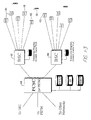
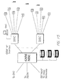
- Figure 1-2 is a diagram of a network architecture showing various system components.
- a preferred communication system is designed around an object-based software architecture which allows for flexibility in interconnection to various networks including public switched telephone networks, AIN, GSM and IS-41 network infrastructures. It is also contemplated that the communication system may interface with a cable television distribution network; however, such an interface may require the addition to the cable television network of a switch architecture, two-way amplifiers, redundancy, and, in order to use the coaxial portion of the cable TV network, a remote antenna subsystem to extend coverage from a base station 104.
- the overall system thus provides flexibility to interface with a variety of different networks depending upon the desired application.
- the system uses internal communications based on ISDN messages, called “notes”, for passing necessary information among components within the system. These "notes” are so named as not to confuse them with the ISDN specific protocol itself.
- Network messages (based on, e.g., Q.921, Q.931 protocols, or others) are converted by the system into “notes” for efficient operation within the hardware platform.
- Fig. 1-2 various components of a preferred system architecture including a plurality of base stations 104 for communicating with user stations 102.
- Each base station 104 may be coupled to a base station controller 105 by any of a variety of linking means 109 including, for example, local area data access (LADA) lines, T1 or fractional T1 lines, ISDN BRI's, cable TV lines, fiber optic cable, digital radio, microwave links, or private lines.
- LADA local area data access
- T1 or fractional T1 lines ISDN BRI's
- cable TV lines fiber optic cable
- digital radio microwave links
- Each base station controller 105 may be connected to a network 106 such as a public switched telephone network (PSTN) or a personal communications system switching center (PCSC) by a variety of network links 108, which include the same basic categories of transport means as the linking means 109.
- Base station controllers 105 may also connect to the network 106 via an X.25 link 114.
- the system of Fig. 1-2 also incorporates the use of "intelligent" base station (IBS) 107 compatible with LEC-based AIN architecture that may be connected directly to a network 106 without the interface of a base station controller 105.
- the intelligent base stations 107 may therefore bypass the base station controllers 105 for local handoffs and switching, and instead perform these functions via the network 106.
- signaling between network elements may be carried out using standard signaling protocols including, for example, SS7 and IS-41.
- the base stations 104 format and send digital information to the base station controller 105 (or directly to the network 106 in the case of an intelligent base station 107).
- the base station controllers 105 concentrate inputs from multiple base stations 104, assist handoffs between base stations 104, and convert and format channel information and signaling information for delivery to the network 106.
- the base station controllers 105 may also manage a local cache VLR database, and may support basic operations, administration and management functions such as billing, monitoring and testing.
- Each base station controller 105 under control of the network 106, may manage local registration and verification of its associated base stations 104 and may provide updates to the network 106 regarding the status of the base stations 104.
- the network 106 connects to the base station controllers 105 for call delivery and outgoing calls.
- the connection between the network 106 and a base station controller 105 may utilize the Bellcore "Generic C" interface which includes Q.921, Q.931 and modifications to Q.931.
- Intelligent base stations 107 may use ISDN messaging for registration, call delivery and handoff over a public telephone switch.
- the intelligent base station 107 may have all the general capabilities of a base station 104 but further incorporate a BRI card, additional intelligence and local vocoding.
- the connection between the network 106 and an intelligent base station 107 may utilize the Bellcore "Generic C" interface which includes Q.921, Q.931 and modifications to Q.931.
- base stations 104 may connect to the network 106 through a defined "A" interface.
- GSM Global System for Mobile communications
- the system may also interconnect to cable television distribution networks.
- the base stations 104 may be miniaturized to the point where they can be installed inside standard cable TV amplifier boxes. Interfacing may be carried out using analog remote antenna systems and digital transport mechanisms. For example, T1 and FT1 digital multiplexer outputs from the cable TV network may be used for interfacing, and basic rate (BRI) ISDN links to transport digital channels.
- BRI basic rate
- Cell site diagnostics may be performed remotely through either the control channel on the digital link resident in the base station 104 or a dial up modem for some implementations. Such diagnostics may be performed on each component board of the base station 104.
- the base stations 104 and base station controllers 105 may be remotely monitored and downloaded with updated software as required.
- user stations 102 can also be downloaded with software over air channels as required for maintenance purposes or for system upgrades.
- the user stations 102 comprise in one embodiment mobile handsets capable of multi-band and/or multi-mode operation.
- the user stations 102 may be multi-mode in that they may be capable of either spread spectrum communication or conventional narrowband communication.
- the user stations 102 may be multi-band in the sense that they may be set to operate on a plurality of different frequencies, such as frequencies in either the licensed or unlicensed frequency bands.
- a user station 102 may be set to operate on any frequency between 1850 and 1990 MHz in 625 kHz steps.
- each user station 102 may have a frequency synthesizers which can be programmed to receive and transmit on any one of 223 frequencies.
- the programmable frequency steps may be in 5 MHz increments, in which case the first channel may be centered at 1852.5 MHz, the next at 1857.5 MHz, and so on.
- the first channel may be centered at 1920.625 MHz, and the channel spacing may be 1.25 MHz across the remainder of the isochronous band.
- the user stations 102 need not operate in the 1910 to 1920 MHz band, which is reserved for asynchronous unlicensed devices.
- multi-band and multi-mode aspects of user stations 102 may be found in US 5,887,020 , US 5,815,525 , US 5,796,772 , US 5,790,587 , US 5,694,414 and US 6,389,059 .
- the multi-band, multi-mode capability enables the user stations 102 take advantage of variety of diverse system architectures as described herein, and to interface with various different networks with a minimum of hardware or software adjustments.
- Base stations 104 may also be provided with multi-band and multi-mode capabilities as described above:
- a base station 104 may poll user stations 102 in the cell 103.
- the base station 104 may repeatedly transmit a major frame 201, comprising a sequence of minor frames 202.
- each minor frame 202 may comprise a polling exchange for a single user station 102, while each major frame 201 may comprise a complete polling sweep of user stations 102 in the cell 103.
- the base station 104 may conduct its polling exchanges using a set of air channels 203.
- Each of the air channels 203 may comprise a separate transmission channel, such as a separate frequency band for FM or AM encoding, a separate spreading code for spread-spectrum encoding, a separate spatial location, or other division of communication slots between base stations 104 and user stations 102.
- the base station 104 may poll every one of its air channels 203 in a predetermined sequence in a single major frame 201.
- the base station 104 may poll every one of its air channels 203 in a single major frame 201, but it will be clear to those of ordinary skill in the art, after perusal of this application, that the base station 104 may restrict its poll to only a portion of its air channels 203 in each major frame 201, so long as all air channels 203 are eventually polled, and in an order so that each user station 102 may determine in which minor frame 202 it should respond.
- Each minor frame 202 may comprise a base transmission 204 by the base station 104, a first gap 205, a user transmission 206 by a user station 102 (if any user station 102 responds), and a second gap 207.
- a user station 102 desiring to establish a communication path may receive the base transmission 204 and determine if the air channel 203 is occupied or not. If not occupied, the user station 102 may respond with its user transmission 206.
- cell radii in order to provide efficient service in low density rural areas, cell radii can be extended to large distances (e.g., beyond 8 miles) by providing the increased guard times as would be required for the longer round trip propagation delays encountered in the larger cells.
- Cells with large radii can be supported by reducing the number of minor frames 202 per major frame 201 to a lesser number (e.g., from 32 to 25). Since such large cell radii will ordinarily be deployed in low population density areas, reduced cell capacity caused by the smaller number of minor frames 202 per major frame 201 is not a severe drawback.
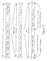
- a base transmission 204 may comprise a header field 207, which may be a fixed length of sixteen bits, a D field 208, which may be a fixed length of eight bits, and a B field 209, which may be a fixed length of 160 bits, or may be a variable length.
- the variable length may be determined in response to the polling loop time and the data rate which must be supported.
- the B field 209 may be 160 bits long.
- the user transmission 206 may comprise like fields as the base transmission 204.
- the header field 207 may comprise an origin bit 210, which may be a "1" bit for base transmissions 204 and may be a "0" bit for user transmissions 206. Other parts of the header field 207 may indicate information about the base transmission 204 or user transmission 206 itself, e.g., what type of message the base transmission 204 or user transmission 206 comprises.
- the header field 207 may also comprise a CSC or CRC code 211 (a cyclic redundancy check) having four bits.
- the D field 208 may comprise control information to be communicated between base stations 104 and user stations 102 once a communication link is established. This control information may generally be used for ISDN communication between base stations 104 and user stations 102, such as control information generally communicated using the ISDN "D channel". Because the D field 208 is separate from but simultaneous with the B field 209 which normally handles the bulk of information transfer due to its higher data rate, the D field 208 may be used for paging applications, notifications (e.g., voice mail), short message service (similar to GSM), or other user applications. Thus, the simultaneous nature of the D field 208 and the B field 209 allows messaging functions even when the user station 102 is "in use”.
- the D field 208 may also comprise a user nickname 212 for communication from the base station 104 and a designated user station 102.
- the user nickname 212 may comprise a temporary identifier for the user station 102 selected by the base station 104.
- the B field 209 may comprise data, voice (encoded digitally or otherwise), or other information. In a preferred embodiment, the B field 209 may also comprise specified information for establishing communication links between base stations 104 and user stations 102. The B field 209 may also comprise its own FCW or CRC code 211 having sixteen bits (with 160 bits of information, a total of 176 bits).
- each minor frame 202 may be about 307 microseconds long
- each air channel 203 in a TDD or TDMA system
- each major frame 201 may be about 20 milliseconds long.
- information may be transmitted at a rate of five bits each 6.4 microseconds, using a 32-ary code-shift keying technique.
- each 6.4 microseconds one of 32 different codes may be transmitted, with 32 different possibilities equalling five bits of information.
- one of 16 different codes may be transmitted, with an additional phase bit on the carrier (or, in a second alternative, more than one phase bit on the carrier), again with 32 different possibilities equalling five bits of information.
- a minor frame 203 may operate in an asymmetric mode in the sense that the greater portion of a minor frame 202 is devoted to either the base transmission 204 or the user transmission 206.
- High speed data transport in either direction i.e., from the base station 104 to the user station 102, or vice versa
- a particular sub-mode of the above described asymmetric mode may be referred to as broadcast mode in which essentially the entire minor frame is devoted to one-way communication.
- one or more broadcast sub-channels may be identified by a special broadcast identifier. Up to 255 broadcast channels may be so identified. For these point-to-multipoint applications, broadcast frames are not acknowledged.
- a user station 102 in a cellular environment preferably has means for controlling transmission power to avoid interference with adjacent cells.
- the nature of a cellular environment with mobile user stations 102 is such that there can arise conflict between user stations 102 at intersecting cell boundaries. This creates the need for some power control in the user stations 102.
- a user station 102 operating at the boundary of coverage of a base station 104 may need to transmit at full power to stay in contact.
- a user station 102 operating relatively close to its own base station 104 may not need to transmit full power to have good contact.
- user stations 102 may maintain adequate contact with base stations 104 without unduly interfering with neighboring cell transmissions, allowing RF channel reuse in nearby cells. Power control may also reduce interference with fixed microwave users and conserve battery power in user stations 102 such as handheld units.
- the present invention achieves power control in one embodiment by use of a power control pulse transmitted periodically from each user station 102.
- a control pulse time 213 and a third gap 214 may be reserved just prior to the start of the minor frame 202, in which the user station 102 transmits a control pulse 215.
- the control pulse 215 provides to the base station 104 a power measurement of the air channel 203 indicative of the path transmission loss and link quality.
- Each user station 102 generally transmits its control pulse 215 in the minor frame 202 allocated to it (e.g., seized by the user station 102).
- the control pulse 215 may be received by the base station 104 and used by the base station 104 to determine information about the communication link it has with the user station 102. For example, the base station 104 may determine, in response to the power, envelope, or phase of the control pulse 215, the direction or distance of the user station 104, and the degree of noise or multipath error to which the communication link with the user station 102 may be prone.
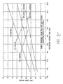
- the base station 104 determines the quality of the received signal including, for example, the received power from the power control pulse 215 and the signal-to-noise or interference ratio. The base station 104 then sends a message to inform the user station 102 to adjust its power if needed. Based on the quality of the received signal, the base station 104 may command the user station 102 to change (increase or decrease) its transmit power by some discrete amount (e.g, in minimum steps of 3 dB) relative to its current setting, until the quality of the control pulse 215 received by the base station 104 is above an acceptable threshold.
- some discrete amount e.g, in minimum steps of 3 dB
- the base station 104 can adjust its own power as well.
- the base station 104 may adjust its power separately for each minor frame 202.
- a preferred power control command pulse from the base station 104 to the user station 102 may be encoded according to Table 5-1 below: Table 5-1 Power Control Command Adjustment 000 No change 001 -3 dB 010 -6 dB 011 -9 dB 100 +3 dB 101 +6 dB 110 +12 dB 111 +21 dB Although preferred values are provided in Table 5-1, the number of power control command steps and the differential in power adjustment between steps may vary depending upon the particular application and the system specifications.
- TDMA Time Division Multiple Access
- the length of the polling loop e.g, the major frame 201
- the latency of the polling loop signals may prevent the use of closed loop power control.
- the described embodiment allows for a power control sequence that may be effectively carried out in a relatively short span of time, thereby allowing closed loop power control.
- the elapsed time encompassing transmission of the control pulse 215, the base transmission 204, and the start of the user transmission 206 is kept relatively short (e.g., less than 500 ⁇ sec or roughly 2.5% of the duration of the major frame 201), allowing system response to be fast enough to counteract small scale multipath fading effects and propagation shadow effects.
- the base station 104 may also use the control pulse 215 to measure the time delay from a user station 102 and thereby estimate the distance of the user station 102 from the base station 104.
- a user station 102 can provide control pulses 215 to multiple base stations 104 for rough location estimation in emergency situations.
- the base station 104 may have a plurality of antennas for reception and transmission on the communication link with the user station 102, and may select one of that plurality of antennas for reception and/or transmission, in response to the determination the base station 104 may make in response to the control pulse 215.
- the base station 104 may make the determination of which antenna to use based on the quality of the signal received from the control pulse 215 transmitted by the user station 102. Because the base station can both receive and transmit on the antenna having the best received signal quality from the control pulse 215, the user stations 102 benefit from antenna selection diversity even though they might not have explicit antenna diversity capabilities at the user station 102.
- the control pulse 215 permits spatial diversity control to be updated during each minor frame 202.
- the base station 104 employs a high speed TDD technique such that the RF channel characteristics do not change within the time of the minor frame 202.
- Information relating to the control pulse 215 for a particular user station 102 may be transferred as information in control traffic from one base station 104 to another base station 104 in the case of a base station assisted handoff.
- control pulse 215 is primarily to reduce battery consumption in user stations 102, to minimize interference of transmissions among neighboring cells 103 which may be operating on the same or adjacent RF channels, and to minimize interference with nearby fixed microwave users.
- the control pulse 215 may also serve as a synchronization preamble for determining the beginning of M-ary data symbols within the minor frame 202.
- a power control command pulse similar in length to the control pulse 215, transmitted by the base station 104 during the base transmission 204 or otherwise may likewise be used as a synchronization preamble at the user station 102, in addition to providing a power control command to adjust the power output level at the user station 102.
- a single base station 104 may communicate with a large number of user stations 102 (e.g., as many as 64 user stations 102) at a given time, each of whose distance from the base station 104 may vary from near zero up to the radius of the cell 103, it may not be practical to control the transmitter power of the base station 104 in order to maintain a near-constant received power level at each user station 102 during each minor frame 202.
- Output power control of the transmitter at the base station 104 could require a large change (e.g., more than 40 dB) in transmit power during each minor frame 202 (e.g., every 625 ⁇ s) of the major frame 201.
- output power control at the base station 104 can be averaged over a longer time interval than each minor frame 202.
- time division duplex permits common antennas to be used for transmit and receive functions at both the base station 104 and the user stations 102, without the need for antenna diplexers. Common antennas can be used to transmit and receive because these functions are separated in time at each of the terminals. Further, because TDD utilizes the same RF frequency for the transmit and receive functions, the channel characteristics are essentially the same for both the base station 104 and a particular user station 102.
- the use of common antennas results in simplicity of the base station 104 and user station 102 terminal designs. Further, use of the same RF frequency and antenna for both transmit and receive functions at the base station 104 and the user station 102 provides reciprocal propagation paths between the base station 104 and user station 102 terminals. This reciprocal nature allows the base station 104 to use the channel sounding of the control pulse 215 transmitted by the user station 102 to determine the two-way path loss between the base station 104 and the user station 102, and also to determine which of the spatial diversity antennas at the base station 104 to use, both to receive from the user station 102 and to transmit to the user station 102.
- an omnidirectional antenna may be used to provide maximum coverage with the fewest base stations 104.
- an omnidirectional antenna may be employed having a vertical gain of approximately 9 dB. The 9 dB of gain permits a relatively large radius cell even with an omnidirectional horizontal pattern.
- directional antennas with 120 degree azimuth beamwidths and 9 dB vertical gain may be used at the base station 104 so that a cell 103 can be sectorized into three parts, with each sector accommodating a full load of user stations 102 (e.g., 32 full duplex user stations 102).
- TDD time division duplex demodulation
- a steered array antenna with up to 20 dB of horizontal directivity can be used.
- Such an antenna is sequentially steered to each user station 102 within a cell 103 at each minor frame 202.
- the same antenna may be used for both transmission and reception, as noted, providing reciprocal forward and reverse link propagation characteristics.
- the steered array antenna may utilize circular polarization so that high level delayed clutter signals reflected from buildings or other obstructions within the beam path do not interfere with the received signals from the user stations 102. As reflected signals are typically reversed in polarization, they will be rejected by the circularly polarized antenna. It should be noted that such high gain, directional antennas also reduce the delay spread in severe multipath environments by rejecting multipath components arriving from outside the main beam of the antenna.
- the user station 102 employs a halfwave dipole antenna which is linearly polarized and provides a gain of 2 dB with an omnidirectional pattern perpendicular to the antenna axis.
- a half wavelength is approximately 3 inches, which fits well within a handset envelope.
- Figure 3 shows message types and a protocol which uses those message types.
- messages may be one of three types: a general poll message 301, a specific poll message 302, and an information message 303.
- a message When a message is transmitted by a user station 102, it is called a "response", e.g., a general poll response 304, a specific poll response 305, and an information response 306.
- a user station 102 may "acquire" a base station 104 by a sequence of handshaking steps.
- the base station 104 may transmit its general poll message 301 on an air channel 203 as part of a minor frame 202.
- the user station 102 receives the general poll message 301 and, if and only if it was received without error, transmits its general poll response 304 on the same air channel 203.
- the general poll message 301 comprises a base ID 308, which may be 32 bits long, which may be recorded by the user station 102.
- the general poll response 304 comprises a user ID 309, which may be 32 bits long, which may be recorded by the base station 104.
- the base ID 308 may be used during handoff, as noted herein.
- the base station 104 may transmit a specific poll message 302, comprising the user ID 309 received by the base station 104 as part of the general poll response 304.
- the specific poll message 302 may be transmitted on the same air channel 203 as the general poll message 301, or may be transmitted on another air channel 203, so long as the user station 102 is able to find it.
- the user station 102 may monitor all air channels 203 for its specific user ID 309.
- the user station 102 receives the specific poll message 302 and, if and only if it was received without error and with the same user ID 309, transmits its specific poll response 305 on the same air channel 203.
- the specific poll response 305 comprises the same user ID 309 as the general poll response 304.
- the specific poll message 302 may be eliminated as redundant.
- the user station 102 may therefore follow the general poll response 304 with a specific poll response 305 on a selected air channel 203.
- This air channel 203 may be designated by the base station 104 in a part of the information field 209 of the general poll message 301, it may be designated by the user station 102 in a part of the information field 209 of the general poll response 304, or it may be selected by the user station 102 in response to an unoccupied air channel 203 (e.g., the user station 102 may seize an unoccupied air channel 203).
- the latter of these three alternatives is presently preferred by the inventors.
- the base station 104 may transmit an information message 303.
- the base station 104 and user station 102 have established a communication link 312 on a designated air channel 203, typically the air channel 203 originally polled by the base station 104, but possibly a different air channel 203.
- the base station 104 may couple a telephone line to that air channel 203, and the user station 102 may begin normal operation on a telephone network (e.g., the user station 102 may receive a dial tone, dial a number, make a telephone connection, and perform other telephone operations).
- the base station 104 and user station 102 may exchange information messages 303 and information responses 306, until the communication link 312 is voluntarily terminated, until faulty communication prompts the user station 102 to re-acquire the base station 104, or until handoff of the user station 102 to another base station 104.
- the base station 104 may advertently fail to respond.
- the lack of response from the base station 104 signals the involved user stations 102 to back off for a calculated time interval before attempting to acquire the same base station 104 using the general poll message 301 and general poll response 304 protocol.
- the back-off time may be based upon the user ID 309, and therefore each user station 102 will back off for a different length of time to prevent future collisions.
- the general poll message is sent by a base station 104 on one or more currently unoccupied air channels 203. Originally, at power-up of the base station 104, the base transmission 204 for all of the air channels 203 may therefore contain the general poll message 301.
- the base station 104 When an incoming telephone call is received at a base station 104, at an incoming-call step 313, the base station 104 transmits a specific poll message 302 with the user ID 309 of the indicated recipient user station 102 (skipping the general poll message 301 and the general poll response 304) on an available air channel 203.
- Each user station 102 listens for the specific poll message 302 repeatedly on each air channel 203 so as to receive the specific poll message 302 within a predetermined time after it is transmitted. Thus each user station 102 may periodically receive each air channel 203 in sequence so as to listen for the specific poll message 302.
- the user station 102 compares the user ID 309 in the message with its own user ID, and if they match, continues with the link-established step 311.
- the base station 104 may thus establish a communication link 312 with any user station 102 within communication range.
- the data transmission rate between a base station 104 and a user station 102 may be expanded or contracted over the duration of the communication link.
- the base station 104 increases the data transmission rate by transmitting multiple information messages 303 to the user station 102 during a major frame 201, essentially allocating multiple minor frames 202 to a single user station 102. These higher data rates, also known as "super rates", are implemented by means of a targeted information message 303.
- the base station 104 may transmit the user nickname 212 in the D field 208, along with information to be transmitted to the designated user station 102 in the B field 209.
- the user station 102 detects the user nickname 212 assigned to it, it receives the targeted information message 303.
- the user nickname 212 may be transmitted by the base station 104 to the user station 102 in the specific poll message 302. In an embodiment where the specific poll message 302 has been eliminated as redundant, the user nickname 212 may be transmitted by the base station 104 to the user station 102 bit-serially in a designated bit of the header field 207.
- the data transmission rate is related to the number of minor frames 202 allocated to a specific user station 102, the data transmission rate increases in steps of, for example, 8 Kbps. It is contemplated that up to the full bandwidth of the base station 104 -- that is, up to all 32 full duplex slots or 256 Kbps (full duplex)-- may be assigned to a single user station 102.
- the invention also provides in another aspect data rates lower than the basic rate (i.e., less than one minor frame 202 per major frame 201 or less than 8 Kbps).
- the lower data rate is accomplished by skipping major frames 201 on a periodic basis.
- data rates such as 4 Kbps, 2 Kbps, and so on can be provided.
- up to 24 consecutive major frames 201 may be skipped, providing a minimum data rate of 320 bps efficiently (i.e., without using rate adaptation). Intermediate rates or even lower rates may be obtained by using rate adaptation.
- each minor frame 202 can be configured with the majority of the minor frame 202 duration allocated to either the base transmission 204 or the user transmission 206, or can be configured with a symmetric distribution in which half of the minor frame 202 duration is allocated to both the base transmission 204 and the user transmission 206.
- voice traffic utilizes a symmetric distribution as either end of the link may send voice traffic. In a data exchange, however, more data is typically sent in one direction and less in the other.
- a higher data rate for the base transmission 204 would be advantageous and is supportable with the described configuration.
- a particular base station 104 or user station 102 may be assigned multiple minor frames 202 within a single major frame 201.
- These high data rate modes can support, for example, enhanced voice quality, video data or broadcast data applications.
- the user station 102 may receive all information messages 303 and transmit all information responses 306 on the same air channel 203 or on specified multiple air channels 203. This arrangement leaves the remainder of the major frame 201 free for other activities.
- one such activity is to interrogate other base stations 104 and maintain network information such as link quality and channel availability at nearby base stations 104 in order to facilitate handoffs from one base station 104 to another base station 104.
- base stations 104 transmit network information as part of the general poll message 301 and the specific poll message 302, in a channel utilization field 314 or otherwise.
- the network information may include, for example, the identity of nearby base stations, the identity or relative amount of free channels at a particular nearby base stations and/or at the current base station, link quality for nearby base stations and/or the current base station, and frequencies and spread spectrum code sets used by the nearby base stations.
- the user station 102 may listen on one or more different air channels 203, other than the one(s) currently being used by the user station 102, for the general poll message 301 and the specific poll message 302 from nearby base stations 104.
- the user station 102 continues to communicate on its designated air channel(s) 203 with its current base station 104 and responds as necessary to information messages 303 from that base station 104.
- the user station 102 does not transmit in response to other nearby base stations 104 and therefore does not occupy air channels 203 of those base stations 104.
- the system may perform either a "make before break” handoff for seamless, undetectable handoffs, or a "break before make” handoff in emergency situations where all communications with a base station 104 are lost prior to a new connection being established.
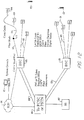
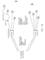
- a "make before break” handoff if the communication link 312 between the base station 104 and the user station 102 is too faulty, then the user station 102 may acquire one of the nearby base stations 104 in like manner as it acquired its current base station 104. Such a handoff procedure may be further explained with reference to Fig. 1-3 .
- a user station 102 presently in communication with a current or original base station 405 has determined it to be desirable to transfer communication to a different base station 104, such as a first terminal base station 410 coupled to a common base station controller 407, or a second terminal base station 406 coupled to a different base station controller 408.
- a handoff to the first terminal base station 410 will be termed an "intra-cluster" handoff, while a handoff to the second terminal base station 406 will be termed an "inter-cluster" handoff.
- the user station 102 determines that a handoff is appropriate, the user station 102 acquires an air channel on the new or terminal base station 410 and notifies the base station controller 407 coupled to the current base station 405 to switch the incoming phone line from the current base station 405 to the new base station 410.
- a handoff procedure may be initiated when the received signal level at a user station 102 falls below an acceptable level. While the user station 102 receives bearer traffic from its originating base station 405, the user station 102 measures the received signal quality (e.g., RSSI) of its communication link 312. The received signal quality value, together with measurements of the current frame error rate and type of errors, determines the overall link quality. If the overall link quality drops below a first threshold (the measurement threshold), the user station 102 begins searching for available air channels 203 (i.e., time slots), first from the originating base station 104, and then (using appropriate frequencies and spread spectrum codes) from neighboring base stations 104 of adjacent or nearby cells 103. The user station 102, as mentioned, preferably has obtained information regarding the identities of neighboring base stations 104 (including spread spectrum code set and frequency information) from the originating base station 405 by downloading the information to the user station 102 during traffic mode or otherwise.
- the received signal quality e.g., RSSI
- the user station 102 scans potential new air channels 203 using the appropriate frequency and/or spread spectrum code set, the user station 102 measures and records the received signal quality.
- the user station 102 reads a field carried in all base transmissions 204 which describes the current time slot utilization of the base station 104.
- the user station 102 uses these two pieces of information to form a figure of merit for the new base station signals, including the originating base station 405, and then sorts the base stations 104 by figure of merit. This procedure allows the user station 102 to evaluate the quality of available air channels 203 for both the originating base station 405 and other nearby base stations 104.
- a time slot interchange (TSI) handoff is considered, which maintains the link to the originating base station 405 on a different air channel 203 than was previously being used by the user station 102.
- TTI time slot interchange
- the user station 102 (during a no-bearer time slot) requests a handoff from the base station 104 with the highest figure of merit (which could be a TSI handoff with the originating base station 405).
- the handoff is requested by seizing an air channel 203, sending a handoff signalling message, and waiting for an acknowledgment from the new base station 410.
- the handoff signaling message contains a description of the circuit connecting the originating base station 405 to the network, which description was passed to the user station 102 at call establishment time. If the new base station 104 accepts the handoff request (by acknowledging), then the new base station 104 becomes the terminal base station 410. Note that the user station 102 maintains its original air channel 203 connection with the originating base station 405 during this handoff procedure, at least until a new air channel 203 is acquired.
- a handoff step 316 the user station 102 transmits to the new base station 410 the base ID 308 of the old base station 405.
- the old base station 405 and new base station 410 may then transfer the handling of any telephone call in progress.
- the terminal base station 410 sends a message in the form of a "note" (as previously described) to its base station controller 407, requesting that the original circuit be switched from the originating base station 405 to the terminal base station 410.
- the base station controller 407 is common to both the originating base station 405 and terminal base station 410, the handoff is termed an intra-cluster event, and the base station controller 407 bridges the circuit from the originating base station 405 to the terminal base station 410.
- the base station controller 407 then sends a circuit-switch-complete note to the originating base station 405 and also to the terminating base station 410, commanding the latter to continue the handoff process.
- the base station controller 408 is not common to both the originating base stations 104 and the terminal base station 406.
- the terminal base station 406 sends a message in the form of a note to its base station controller 408, requesting that the original circuit be switched from the originating base station 405 to the terminal base station 406.
- the base station controller 408 translates the handoff note into the signaling language of the network host 409 (e.g, a PCSC) and requests an inter-cluster handoff at the network level.
- the host network 409 cannot accept a handoff request from a terminating base station controller 408, in which case an intermediate step is taken.
- the handoff request may be sent via an X.25 link to the base station controller 407 connected to the originating base station 405.
- the originating base station controller 407 then translates the handoff request and relays it to the network host 409.
- the network host 409 acknowledges the circuit switch to the originating base station controller 407, which then sends a circuit-switch-complete note to the terminal base station 406.
- the terminal base station 406 When the terminal base station 406 receives the circuit-switch-complete note, the terminal base station 406 begins paging the user station 102 with a specific poll, and the originating base station 405 signals the user station 102 to transfer to the terminal base station 406. When the user station 102 receives the signal to transfer to the terminal base station 406, or if the link is lost during the handoff process, the user station 102 switches to the terminal base station 406 and searches for a specific poll message 302. When the user station 102 receives the specific poll message 302, the user station 102 completes the connection to the terminal base station 406, and the handoff procedure is finished.
- the user station 102 will search for the highest quality base station 104 on its list of potential handoffs, and attempt a handoff without communication with its previous base station 405. This capability allows the user station 102 to recover from situations in which the original link was broken before the normal handoff procedure could be completed.
- An intra-cluster handoff including re-establishment of bearer channel traffic, may ordinarily take from less than 10 milliseconds to as much as 40 milliseconds. Since under normal circumstances the handoff time is less than one polling loop interval, bearer packets will continue to the user station 102 with no interruption. Inter-cluster handoff times are partially dependent upon the delays inherent in the host network 409 and are not always easily predictable.
- a unique aspect of the above described "mobile directed” or “mobile centric” handoff technique is that the user station 102 makes the decision to handoff between cells and directs the base station controller or network to make a line switch once an alternative base station 104 is acquired.
- This approach is quite different from a "network directed” or “network centric” approach such as used in systems such as AMPS, IS-54 cellular, and GSM.
- the mobile centric approach also differs significantly from so-called “Mobile Assisted Handoff” (MAHO) in which the network collects information and directs all or most of the handoff functions, thereby utilizing the user station 102 primarily as an additional listening post with the network still directing the handoff.
- MAHO Mobile Assisted Handoff
- the MAHO technique therefore ordinarily requires significant signaling and messaging between base stations, base station controllers, and switches, causing handoffs to take much longer than with the mobile centric techniques described herein.
- a major benefit of the mobile centric approach is that it may allow for mobile speed handoffs (e.g., 65 MPH) even in very small or very large cells, such as cells ranging from as small as under 1000 feet to as large as 20 miles in diameter.
- the system is also capable of performing a "break before make” type of handoff as well.
- a "break before make” handoff is typified in a situation where sudden shadowing occurs, such as when a connection with the current base station 405 is lost due to a severe signal blockage (e.g. worse than 40 dB) near the limit of the cell range such as can occur when turning a corner quickly in a dense urban high rise area.
- the user station 102 checks its previously created "priority list" of available base stations in the vicinity and attempts to establish contact with a new base station 104, perhaps on a new frequency and/or a new time slot.
- the user station 102 may include as part of its control logic a "persistence" parameter which will preclude call tear down from occurring before a duplex connection is fully reestablished.
- the true "hard handoff" problem i.e., a lost air channel
- the handoff may ordinarily be accomplished in as little as 16 to 250 milliseconds.
- complete loss of a link in traditional cellular architectures becomes a "dropped call.”
- One problem that may occur during handoff is a situation in which there are repeated attempts to switch between two or more base stations 104 during times, for example, when the measured quality of the received signals from two competing base stations 104 is very close, or when environmental effects cause rapidly changing deviations in the relative measured signal quality of the signals from competing base stations 104.
- the repeated switching between competing base stations 104 may be referred to as "thrashing" and may have the undesirable effect of consuming excess capacity from the network.
- hysteresis measurements from multiple base stations 104 may be maintained by the user station 102 so that a handoff does not occur until the quality of the signal from a new base station 104 exceeds the quality of the signal of the original base station 405 by a predetermined margin. In such a manner, important air channel resources in the network may be preserved.
- a time slot interchange may be performed wherein one or both of the conflicting user stations 102 are assigned different minor frames 202 within their respective major frames 201 to eliminate further collisions.
- TTI time slot interchange
- Such a procedure may be viewed as the time domain equivalent of dynamic channel allocation as the system either assigns an unoccupied air channel 203 to the user station 102 or switches the user station's 102 minor frame 202 with that of another user station 102 in the same cell 103 which is geographically removed from the interference.
- the protocol of the invention protects communications against errors in several ways: protocol handshaking, user ID verification and reverification, and synchronization by reacquiring the base station. Handshaking, verification and synchronization protect both the base station 104 and the user station 102 from receiving telephone calls in progress on any other air channels 203.
- Handshaking provided by the general poll step 307 and the specific poll step 310 requires that the proper message having the proper header be transmitted and received, and in the proper sequence.
- the header field 207 (sixteen bits) is protected by a CRC code 211 (four bits); an error in the header field 207 or in the CRC code 211 indicates an error and will cause the protocol to restart handshaking with the general poll step 307.
- the user ID is verified twice, once by the base station 104 and once by the user station 102.
- the user ID 309 is protected by a CRC code 211 (sixteen bits), in like manner as the CRC code 211 for the header field 207.
- An error in the user ID 309 or in the CRC code 211 will cause the protocol to restart handshaking with the general poll step 307.
- the base station 104 and the user station 102 are protected against drift and/or desynchronization, even when transmission or reception are interrupted.
- the base station 104 and user station 102 each independently stop sending data in information messages 303 and information responses 306, and return to the specific poll step 310 for resynchronization.
- the base station 104 and the user station 102 may determine resynchronization by means of a designated bit in the header field 207.
- the base station 104 transmits the specific poll message 302 and the user station 102 searches the major frame 201 for a specific poll message 302 having a user ID 309 which matches its own user ID 309. After this handshaking succeeds, the base station 104 and user station 102 return to the link-established step 311 and continue transmitting and receiving information messages 303 and information responses 306.
- This technique for recovery from desynchronization also called “reacquiring the base station,” has the advantage that both the base station 104 and the user station 102 independently reverify the user ID 309 before communication is resumed. This assures that the base station 104 and the user station 102 stay in synchrony and communicate only on the agreed air channel 203. Should the base station 104 and the user station 102 be unable to reestablish the communication link 312, the telephone call will be terminated by the base station 104.
- the base station 104 also repeatedly and periodically transmits the user ID 309 in the D field 208 of the information message 303.
- the user station 102 checks the user ID 309 to assure that the base station 104 and the user station 102 are each communicating on the proper air channel 203. If this user ID 309 does not match, it returns to the specific poll step 310 to reacquire the base station 104, as noted above.
- the protocol described above provides flexibility with a small number of unique messages.
- the protocol is immune to changes in polling loop length and in the number of air channels allowed.
- the number of simultaneous users is therefore responsive to voice compression and data rate constraints and not by the protocol.
- the protocol also provides for an unlimited number of user stations in a given area, with the provision that the number of simultaneous calls cannot exceed the number of air channels.
- An unlimited number of base stations are also supported, making base station geography a function of available frequencies and range, not of protocol.
- the ability to interrogate and acquire alternate base stations in the presence of faulty communication provides for the expansion of a microcell network which may use base station handoff to route calls to base stations within range.
- the TDMA frame times for all base stations 104 within a geographical region are preferably synchronized to within a specified tolerance. For example, in one embodiment, all base stations 104 begin transmissions for the same frame within 6 microseconds.
- the primary data timing standard in a digital network backhaul system such as T1, ISDN BRI, or PRI, is the public switched telephone network (PSTN) timing standard.
- PSTN public switched telephone network
- a GPS receiver is used at each base station controller 105 (and optionally at each base station 104) to generate the primary reference timing marker for the TDMA frame timing. This marker is captured at the base station controller 105 every second and transmitted to the attached base stations 104.
- a base station controller may temporarily turn off any major frame 201 or minor frame 202 of a given cell 103 which may be interfering with a neighboring cell 103.
- Each base station 104 provides the basic TDMA loop timing structure for its cell or sector.
- a synchronization preamble in the form a control pulse 215 or power control command is transmitted at the beginning of each minor frame 202 by the user station 102 and the base station 104, respectively.
- a digital correlator i.e., a matched filter
- the internal synchronization pulse may then be used to synchronize the start of M-ary symbol detection process.
- the Omnipoint handover is MS controlled and divided into 16 steps.
- the MS will search for the highest quality BS and attempt a handover without communication with its previous BS. This allows the MS to recover from situations in which the original link has degenerated.
- the total delay between the time that a handover is required and the completion of the handover, including the re-establishment of the bearer channel is typically less than 10 ms.
- the maximum intra-cluster handover time assuming that communications with the terminal is error free, is approximately 40 ms.
- Inter-cluster handover delay is partially dependent upon the delays inherent in the host PCSC and are beyond the scope of this discussion. Delays induced by the over-the-air portion of the system remain minimal, i.e., in the 10 to 40 ms range.
- Intra-BS handover or Time Slot Interchange handover
- the delay is less than one polling loop, 20 ms, and typically less than 10ms. Since there is no switching delay, bearer packets will continue to the MS with no interruption.
- Break before make handovers will typically take less than 250 msec. assuming adequate RF coverage from at least one base, regardless of whether intra or inter cluster.
- the inter-cluster switching time is partially dependent upon delays inherent in the host PCSC and varies from network architecture to network architecture and are beyond the scope of this discussion.
- data information which is transmitted from transmitter to receiver
- data information which is transmitted from transmitter to receiver
- data could comprise data, voice (encoded digitally or otherwise) error-correcting codes, control information, or other signals, and that this would be within the scope and spirit of the invention.
- air channels may be multiplexed by other means, including FDMA (frequency division multiplexing), by assigning air channels to differing frequency bands, CDMA (code division multiplexing), by assigning air channels to differing spread-spectrum spreading codes, other multiplexing techniques, or combinations of these multiplexing techniques, and that this would be within the scope of the invention.
- FDMA frequency division multiplexing
- CDMA code division multiplexing
Abstract
Description
- This invention relates to the field of communications, and particularly to communication systems using spread spectrum techniques and to over-the-air protocols for mobile telephones.
- A mobile telephone system may generally comprise a set of "user stations", typically mobile and the endpoints of a communication path, and a set of "base stations", typically stationary and the intermediaries by which a communication path may be established or maintained. In a mobile telephone system, one important concern is the ability of mobile stations to communicate with base stations in a simple, flexible and rapid manner. The communication protocol between user stations and base stations should be rapid, so that user stations are not required to wait to establish a communication path. The protocol should be simple, so that user stations need not incorporate expensive equipment to implement it. The protocol should be flexible, so that user stations may establish communication environments as reasonably possible.
- Accordingly, it would be advantageous to provide a simple and flexible over-air protocol for use with a mobile telephone system. One class of systems in which this would be particularly advantageous is that of personal communication systems, particularly those with hand-held telephones in a microcell or other type of cellular communication system.
-
US 5,159,593 discloses a TDMA communication system in which a subscriber unit monitors the strength of signals received from base stations and when the subscriber unit moves out of the range of a base station, the subscriber unit sends a request for a time slot assignment to a new base station. - The present invention provides a method for handoff in a time division multiple access communication system, comprising the steps of:
- communicating between a user station and a first base station in a first time slot of a time frame;
- monitoring, at said user station in communication with said first base station, a received signal quality of messages transmitted in said first time slot, and deriving a link quality measurement thereby;
- comparing said link quality measurement against a handover threshold level;
- when said link quality measurement falls below said handover threshold level, initiating at said user station a handoff procedure to a new base station, said handoff procedure comprising the steps of:
- receiving at said user station a general poll message from said new base station in a second time slot, said general poll message indicating an unoccupied time slot;
- transmitting, in said second time slot and in response to said general poll message, a general poll response message indicative of a request to seize said slot and containing a user station identifier from said user station to said new base station;
- receiving said general poll response message at said new base station;
- transmitting, in said second time slot and in response to said general poll response message, a specific poll message from said new base station to said user station, said specific poll message comprising the user station identifier;
- receiving said specific poll message at said user station;
- transmitting, in said second time slot, a handoff signalling message containing a description of the circuit connecting the first base station to the network from said user station to aid new base station;
- transmitting, in said second time slot and in response to said handoff signalling message, a handoff acknowledgement signal from said new base station to said user station;
- receiving said handoff acknowledgement signal at said user station,
- transmitting a base identification of said first base station from said user station to said new base station; and
- transferring an in-progress call from said first base station to said new base station.
- The invention provides in one aspect a simple and flexible over-air protocol for use with a mobile telephone system, such as a Personal Communication System (PCS) with hand-held telephones which may use a cellular communication system A preferred embodiment is adapted to "pocket phones", i.e., small hand-held telephones which may use a cellular communication technique, but the invention may be used with any cellular or mobile telephone system. The protocol defines a method in which user stations, such as cellular or mobile handsets, communicate with one or more base stations to place and receive telephone calls. The protocol provides air-channel agility between base stations and user stations, while providing a secure voice or data link and the ability to handoff calls between base stations while they are in progress.
- In a preferred embodiment, each base station may have a set of "air channels" which it polls, e.g. by transmitting to each one in sequence. The air channels supported by each base station are referred to as a "polling loop" for a particular base station. A user station may receive information on an unoccupied air channel, receive the base station's transmission, and transmit information to the base station. Each base station may therefore simultaneously maintain communication with as many user stations as there are air channels in its polling loop. The ability of a user station to communicate on any unoccupied air channel makes the protocol air-channel agile. Each base station continually transmits on each one of its air channels in a predetermined sequence. Each base station transmission may be followed by a first gap, a user station transmission (if some user station attempts to communicate), and a second gap, before the base station transmits on the next air channel. A base station transmission, first gap, user station transmission, and second gap are collectively called a "minor frame". A polling loop in which each air channel is polled is called a "major frame".
- In a preferred embodiment, stability of user station and base station clocks may define the air channels, gaps, and minor frames. The user station may synchronize itself to the base station's clock by detecting a minor frame and by adjusting its clock to be in synchrony with the base station when the first bit sequence of the minor frame is detected. The stability of the user station and base station clocks may then hold the user station and base station in synchronization, as long as the user station is periodically able to receive transmissions from the base station. Should reception in either direction be interrupted for too long, the base station and user station clocks may drift apart and the user station may need to reacquire the transmission from the base station.
- Handoffs are preferably initiated from the user station which continually monitors available air channels from the same and competing base stations during dead time. A user station may handoff within the same polling loop to establish communication in a new minor frame, or may handoff in such a manner to establish communication in a new minor frame within a polling loop of a different base station. In the latter case, a base station controller may assist in transferring the call from one base station to another.
- The invention provides in yet another aspect for closed loop power control in the user stations by monitoring and adjusting the user station power at regular intervals, such as once in each major frame. The control of user station power serves to reduce intercell interference and prolong battery life in mobile handsets.
- Variable data rates provided in another aspect of the present invention. A user station may increase its data rate by transmitting and/or receiving in multiple minor frames during a major frame, or may reduce its data rate by transmitting and/or receiving in fewer than every major frame.
-
- Figure 1A is a diagram of a communication system having base stations and user stations.
-
Figure 1-1 is a diagram of a communication system with alternate network interconnections. -
Figure 1-2 is a diagram of a network architecture showing various system components. -
Figure 1-3 is a diagram of a network architecture showing connections between base stations and a network. -
Figures 1-4 ,1-5 ,1-6 , and1-7 are diagrams of network architectures showing various system components. -
Figures 1-8 and1-9 are diagrams of a handset air channel acquisition procedure for an embodiment of the invention. -
Figure 2 is a diagram of frame and message formats in a polling loop. -
Figure 2-1 is a diagram of a preferred cellular environment in which the invention may operate. -
Figure 2-2 is a diagram of a TDMA/TDD frame structure for an embodiment of the invention. -
Figure 2-3 is a diagram of a polling loop for an embodiment of the invention. -
Figure 2-4 is a block diagram of a speech coder for an embodiment of the invention. -
Figure 2-5 is a functional block diagram of a speech coder control path for an embodiment of the invention. -
Figure 2-6 is a diagram of a packet structure for an embodiment of the invention. -
Figure 2-7 and2-8 are diagrams showing time slot assignments for an embodiment of the invention. -
Figure 2-9 is a diagram of a speech coder buffer structure for an embodiment of the invention. -
Figure 3 is a diagram showing formats for message types. -
Figures 3-1 and3-2 are estimated cell radii coverage charts for an embodiment of the invention. - In a preferred embodiment, it is contemplated that communication between base stations and user stations will be conducted using a spread-spectrum technique. There are at least three methods for establishing synchronization and communication, each preferably using an M-ary technique in which multiple bits of data are transmitted for each spread-spectrum symbol, e.g., by transmitting and receiving multiple different spreading codes, and interpreting the received one of those multiple different spreading codes at the receiver to indicate multiple data bits. Synchronization may be accomplished either by (1) automatic synchronization disclosed in
US 5,761,239 by (2) synchronizing with matched filters, by (3) demodulation and despreading using sliding correlators, or by (4) a combination of these techniques, e.g., matched filters for synchronization plus sliding correlators for demodulation and despreading, or matched filters for synchronization plus autosynchronization for demodulation and despreading. - Figure 1A is a diagram of a communication system having base stations and user stations.
- A
communication system 101 for communication among a plurality ofuser stations 102 may include a plurality ofcells 103, each with abase station 104, typically located at the center of thecell 103. Each station (both thebase stations 104 and the user stations 102) may generally comprise a receiver and a transmitter. Theuser stations 102 andbase stations 104 preferably communicate using time division multiple access (TDMA) or time division duplex (TDD) techniques as further described herein, in which specified time segments or major frames are divided into assigned time slots or minor frames for individual communication. -
Figure 2-1 is a diagram of a preferred cellular environment in which the invention may operate. A geographical region is divided into a plurality ofcells 103. Associated with eachcell 103 is an assigned frequency and an assigned spread spectrum code. Preferably, three different frequencies F1, F2 and F3 are assigned in such a manner that no two adjacent cells have the same assigned frequency F1, F2 or F3. The effect of such a frequency reuse pattern is to minimize interference between adjacent cells. - To further reduce the possibility of intercell interference, different orthogonal spread spectrum codes C1 through C6 are assigned as shown in
adjacent clusters 110. Although six spread spectrum codes C1 through C6 are shown inFig. 2-1 , it is contemplated that fewer or more spread spectrum codes may be suitable depending upon the particular information. Further information regarding a preferred cellular environment may be found inUS 5,402,413 . - The use of spread spectrum for carrier modulation permits a very efficient frequency reuse factor of N = 3 for allocating different carrier frequencies F1, F2 and F3 to
adjacent cells 103. Interference betweencells 103 using the same carrier frequency F1, F2 or F3 is reduced by the propagation loss due to the distance separating the cells 103 (no twocells 103 using the same frequency F1, F2 or F3 are less than twocells 103 in distance away from one another), and also by the spread spectrum processing gain ofcells 103 using the same carrier frequencies F1, F2 or F3. - The preferred spread spectrum bandwidth may differ according to the frequency band of operation. When operating in the PCS A, B, or C frequency bands, each of which is 15 Mhz wide, the center frequencies F1, F2 and F3 are preferably located at 2.5 Mhz, 7.5 Mhz, and 12.5 Mhz, respectively, from the lowest band edge of the A, B or C frequency band.
- The PCS D, E, or F bands, on the other hand, are each 5 Mhz wide, which is the same bandwidth as a preferred spreading bandwidth for a spread spectrum signal used in the particular cellular environment. Consequently, a single carrier frequency is placed in the center of the D, E or F band, and a frequency reuse factor of N = 1 is used because the spread spectrum signal covers the entire available bandwidth. Because an N = 1 frequency reuse pattern is used, the required intercell interference rejection must be obtained by spread spectrum code orthogonality and/or the use of sectorized antenna patterns. The exchange of interfering air channels or time slots, as described elsewhere herein, may also be used to mitigate intercell interference.
- When operating in the PCS unlicensed band, which has a bandwidth of 20 Mhz divided into individual channel only 1.25 Mhz wide, the spread spectrum chipping rate may be reduced to approximately 1.25 Mcps. The TDMA burst rate, or number of TDMA time slots (or minor frames) in each polling loop, may also be reduced to maintain the required spread spectrum processing gain for rejecting intercell interference. A non-spread spectrum TDMA/TDD signal modulation format for operation in the unlicensed band may also be provided.
-
Figure 1-2 is a diagram of a network architecture showing various system components. - A preferred communication system is designed around an object-based software architecture which allows for flexibility in interconnection to various networks including public switched telephone networks, AIN, GSM and IS-41 network infrastructures. It is also contemplated that the communication system may interface with a cable television distribution network; however, such an interface may require the addition to the cable television network of a switch architecture, two-way amplifiers, redundancy, and, in order to use the coaxial portion of the cable TV network, a remote antenna subsystem to extend coverage from a
base station 104. - The overall system thus provides flexibility to interface with a variety of different networks depending upon the desired application. To allow interconnection to diverse networks, the system uses internal communications based on ISDN messages, called "notes", for passing necessary information among components within the system. These "notes" are so named as not to confuse them with the ISDN specific protocol itself. Network messages (based on, e.g., Q.921, Q.931 protocols, or others) are converted by the system into "notes" for efficient operation within the hardware platform.
- In
Fig. 1-2 is shown various components of a preferred system architecture including a plurality ofbase stations 104 for communicating withuser stations 102. Eachbase station 104 may be coupled to abase station controller 105 by any of a variety of linking means 109 including, for example, local area data access (LADA) lines, T1 or fractional T1 lines, ISDN BRI's, cable TV lines, fiber optic cable, digital radio, microwave links, or private lines. As an illustration shown inFig. 1-2 , a plurality ofbase stations 104 may be coupled tobase station controller 105 by first connecting to a coaxial cable 111 which is thereafter coupled to afiber optic cable 113 at a fiber node 112. Thefiber optic cable 113 is coupled to thebase station controller 105 as shown. - Each
base station controller 105 may be connected to a network 106 such as a public switched telephone network (PSTN) or a personal communications system switching center (PCSC) by a variety ofnetwork links 108, which include the same basic categories of transport means as the linking means 109.Base station controllers 105 may also connect to the network 106 via an X.25link 114. - The system of
Fig. 1-2 also incorporates the use of "intelligent" base station (IBS) 107 compatible with LEC-based AIN architecture that may be connected directly to a network 106 without the interface of abase station controller 105. Theintelligent base stations 107 may therefore bypass thebase station controllers 105 for local handoffs and switching, and instead perform these functions via the network 106. In AIN based architectures, signaling between network elements may be carried out using standard signaling protocols including, for example, SS7 and IS-41. - In operation, the
base stations 104 format and send digital information to the base station controller 105 (or directly to the network 106 in the case of an intelligent base station 107). Thebase station controllers 105 concentrate inputs frommultiple base stations 104, assist handoffs betweenbase stations 104, and convert and format channel information and signaling information for delivery to the network 106. Thebase station controllers 105 may also manage a local cache VLR database, and may support basic operations, administration and management functions such as billing, monitoring and testing. Eachbase station controller 105, under control of the network 106, may manage local registration and verification of its associatedbase stations 104 and may provide updates to the network 106 regarding the status of thebase stations 104. - The network 106 connects to the
base station controllers 105 for call delivery and outgoing calls. The connection between the network 106 and abase station controller 105 may utilize the Bellcore "Generic C" interface which includes Q.921, Q.931 and modifications to Q.931. -
Intelligent base stations 107 may use ISDN messaging for registration, call delivery and handoff over a public telephone switch. Theintelligent base station 107 may have all the general capabilities of abase station 104 but further incorporate a BRI card, additional intelligence and local vocoding. The connection between the network 106 and anintelligent base station 107 may utilize the Bellcore "Generic C" interface which includes Q.921, Q.931 and modifications to Q.931. - If the network 106 is a GSM network, then
base stations 104 may connect to the network 106 through a defined "A" interface. Features and functionality of GSM are passed to and from thebase stations 104 over the "A" interface in a manner that is transparent to the end user. - As noted, the system may also interconnect to cable television distribution networks. The
base stations 104 may be miniaturized to the point where they can be installed inside standard cable TV amplifier boxes. Interfacing may be carried out using analog remote antenna systems and digital transport mechanisms. For example, T1 and FT1 digital multiplexer outputs from the cable TV network may be used for interfacing, and basic rate (BRI) ISDN links to transport digital channels. - Cell site diagnostics may be performed remotely through either the control channel on the digital link resident in the
base station 104 or a dial up modem for some implementations. Such diagnostics may be performed on each component board of thebase station 104. In addition, thebase stations 104 andbase station controllers 105 may be remotely monitored and downloaded with updated software as required. Similarly,user stations 102 can also be downloaded with software over air channels as required for maintenance purposes or for system upgrades. - The
user stations 102 comprise in one embodiment mobile handsets capable of multi-band and/or multi-mode operation. Theuser stations 102 may be multi-mode in that they may be capable of either spread spectrum communication or conventional narrowband communication. Theuser stations 102 may be multi-band in the sense that they may be set to operate on a plurality of different frequencies, such as frequencies in either the licensed or unlicensed frequency bands. - For example, a
user station 102 may be set to operate on any frequency between 1850 and 1990 MHz in 625 kHz steps. Thus, eachuser station 102 may have a frequency synthesizers which can be programmed to receive and transmit on any one of 223 frequencies. If theuser station 102 operates solely in the licensed PCS band, however, the programmable frequency steps may be in 5 MHz increments, in which case the first channel may be centered at 1852.5 MHz, the next at 1857.5 MHz, and so on. If operating in the isochronous band between 1920 and 1930 MHz, the first channel may be centered at 1920.625 MHz, and the channel spacing may be 1.25 MHz across the remainder of the isochronous band. Theuser stations 102 need not operate in the 1910 to 1920 MHz band, which is reserved for asynchronous unlicensed devices. - Further detail regarding the multi-band and multi-mode aspects of
user stations 102 may be found inUS 5,887,020 ,US 5,815,525 ,US 5,796,772 ,US 5,790,587 ,US 5,694,414 andUS 6,389,059 . - The multi-band, multi-mode capability enables the
user stations 102 take advantage of variety of diverse system architectures as described herein, and to interface with various different networks with a minimum of hardware or software adjustments. -
Base stations 104, likeuser stations 102, may also be provided with multi-band and multi-mode capabilities as described above: -
Figure 2 shows frame and message formats in a polling loop. - In a
single cell 103, abase station 104 may polluser stations 102 in thecell 103. Thebase station 104 may repeatedly transmit amajor frame 201, comprising a sequence ofminor frames 202. As noted herein, eachminor frame 202 may comprise a polling exchange for asingle user station 102, while eachmajor frame 201 may comprise a complete polling sweep ofuser stations 102 in thecell 103. - In a preferred embodiment, the
base station 104 may conduct its polling exchanges using a set ofair channels 203. Each of theair channels 203 may comprise a separate transmission channel, such as a separate frequency band for FM or AM encoding, a separate spreading code for spread-spectrum encoding, a separate spatial location, or other division of communication slots betweenbase stations 104 anduser stations 102. In a preferred embodiment, thebase station 104 may poll every one of itsair channels 203 in a predetermined sequence in a singlemajor frame 201. - While in a preferred embodiment, the
base station 104 may poll every one of itsair channels 203 in a singlemajor frame 201, but it will be clear to those of ordinary skill in the art, after perusal of this application, that thebase station 104 may restrict its poll to only a portion of itsair channels 203 in eachmajor frame 201, so long as allair channels 203 are eventually polled, and in an order so that eachuser station 102 may determine in whichminor frame 202 it should respond. - Each
minor frame 202 may comprise abase transmission 204 by thebase station 104, afirst gap 205, a user transmission 206 by a user station 102 (if anyuser station 102 responds), and asecond gap 207. During thebase transmission 204, auser station 102 desiring to establish a communication path may receive thebase transmission 204 and determine if theair channel 203 is occupied or not. If not occupied, theuser station 102 may respond with its user transmission 206. - In one embodiment, in order to provide efficient service in low density rural areas, cell radii can be extended to large distances (e.g., beyond 8 miles) by providing the increased guard times as would be required for the longer round trip propagation delays encountered in the larger cells. Cells with large radii can be supported by reducing the number of
minor frames 202 permajor frame 201 to a lesser number (e.g., from 32 to 25). Since such large cell radii will ordinarily be deployed in low population density areas, reduced cell capacity caused by the smaller number ofminor frames 202 permajor frame 201 is not a severe drawback. - In a preferred embodiment, a
base transmission 204 may comprise aheader field 207, which may be a fixed length of sixteen bits, aD field 208, which may be a fixed length of eight bits, and aB field 209, which may be a fixed length of 160 bits, or may be a variable length. In an embodiment using a variable-length B field 209, the variable length may be determined in response to the polling loop time and the data rate which must be supported. For example, in a preferred embodiment of a 30-channel system, theB field 209 may be 160 bits long. - In a preferred embodiment, the user transmission 206 may comprise like fields as the
base transmission 204. - The
header field 207 may comprise anorigin bit 210, which may be a "1" bit forbase transmissions 204 and may be a "0" bit for user transmissions 206. Other parts of theheader field 207 may indicate information about thebase transmission 204 or user transmission 206 itself, e.g., what type of message thebase transmission 204 or user transmission 206 comprises. Theheader field 207 may also comprise a CSC or CRC code 211 (a cyclic redundancy check) having four bits. - The
D field 208 may comprise control information to be communicated betweenbase stations 104 anduser stations 102 once a communication link is established. This control information may generally be used for ISDN communication betweenbase stations 104 anduser stations 102, such as control information generally communicated using the ISDN "D channel". Because theD field 208 is separate from but simultaneous with theB field 209 which normally handles the bulk of information transfer due to its higher data rate, theD field 208 may be used for paging applications, notifications (e.g., voice mail), short message service (similar to GSM), or other user applications. Thus, the simultaneous nature of theD field 208 and theB field 209 allows messaging functions even when theuser station 102 is "in use". - During link expansion, described with regard to
figure 3 herein, theD field 208 may also comprise auser nickname 212 for communication from thebase station 104 and a designateduser station 102. Theuser nickname 212 may comprise a temporary identifier for theuser station 102 selected by thebase station 104. - The
B field 209 may comprise data, voice (encoded digitally or otherwise), or other information. In a preferred embodiment, theB field 209 may also comprise specified information for establishing communication links betweenbase stations 104 anduser stations 102. TheB field 209 may also comprise its own FCW orCRC code 211 having sixteen bits (with 160 bits of information, a total of 176 bits). - In a preferred embodiment, there may be 32
air channels 203; themajor frame 201 may therefore comprise 32minor frames 202 in sequence. Thus, eachminor frame 202 may be about 307 microseconds long, each air channel 203 (in a TDD or TDMA system) may be about 667 microseconds long, and eachmajor frame 201 may be about 20 milliseconds long. In a preferred embodiment, there may be 160 bits transmitted perair channel 203; thus the 32-channel system would have about a 256 kilobits/second total two-way data rate. Other time values are shown in the figure. - In a preferred embodiment, information may be transmitted at a rate of five bits each 6.4 microseconds, using a 32-ary code-shift keying technique. Thus, each 6.4 microseconds, one of 32 different codes may be transmitted, with 32 different possibilities equalling five bits of information. In an alternative preferred embodiment, one of 16 different codes may be transmitted, with an additional phase bit on the carrier (or, in a second alternative, more than one phase bit on the carrier), again with 32 different possibilities equalling five bits of information.
- In one embodiment, a
minor frame 203 may operate in an asymmetric mode in the sense that the greater portion of aminor frame 202 is devoted to either thebase transmission 204 or the user transmission 206. High speed data transport in either direction (i.e., from thebase station 104 to theuser station 102, or vice versa) can be provided in the asymmetric mode, with or without acknowledgment and/or ARQ. - A particular sub-mode of the above described asymmetric mode may be referred to as broadcast mode in which essentially the entire minor frame is devoted to one-way communication. In the broadcast mode, one or more broadcast sub-channels may be identified by a special broadcast identifier. Up to 255 broadcast channels may be so identified. For these point-to-multipoint applications, broadcast frames are not acknowledged.
- A
user station 102 in a cellular environment preferably has means for controlling transmission power to avoid interference with adjacent cells. Unlike a fixed station environment, in which antenna locations, patterns and fixed station transmission power may be adjusted for minimal interference with other fixed stations, the nature of a cellular environment withmobile user stations 102 is such that there can arise conflict betweenuser stations 102 at intersecting cell boundaries. This creates the need for some power control in theuser stations 102. For example, auser station 102 operating at the boundary of coverage of abase station 104 may need to transmit at full power to stay in contact. On the other hand, auser station 102 operating relatively close to itsown base station 104 may not need to transmit full power to have good contact. By proper power control,user stations 102 may maintain adequate contact withbase stations 104 without unduly interfering with neighboring cell transmissions, allowing RF channel reuse in nearby cells. Power control may also reduce interference with fixed microwave users and conserve battery power inuser stations 102 such as handheld units. - The present invention achieves power control in one embodiment by use of a power control pulse transmitted periodically from each
user station 102. After establishment of a communication link, described with regard toFig. 3 herein, a control pulse time 213 and athird gap 214 may be reserved just prior to the start of theminor frame 202, in which theuser station 102 transmits acontrol pulse 215. Thecontrol pulse 215 provides to the base station 104 a power measurement of theair channel 203 indicative of the path transmission loss and link quality. Eachuser station 102 generally transmits itscontrol pulse 215 in theminor frame 202 allocated to it (e.g., seized by the user station 102). - The
control pulse 215 may be received by thebase station 104 and used by thebase station 104 to determine information about the communication link it has with theuser station 102. For example, thebase station 104 may determine, in response to the power, envelope, or phase of thecontrol pulse 215, the direction or distance of theuser station 104, and the degree of noise or multipath error to which the communication link with theuser station 102 may be prone. - In response to receiving the
control pulse 215, thebase station 104 determines the quality of the received signal including, for example, the received power from thepower control pulse 215 and the signal-to-noise or interference ratio. Thebase station 104 then sends a message to inform theuser station 102 to adjust its power if needed. Based on the quality of the received signal, thebase station 104 may command theuser station 102 to change (increase or decrease) its transmit power by some discrete amount (e.g, in minimum steps of 3 dB) relative to its current setting, until the quality of thecontrol pulse 215 received by thebase station 104 is above an acceptable threshold. - Similarly, if the
base station 104 knows the power setting of theuser station 102, then thebase station 104 can adjust its own power as well. Thebase station 104 may adjust its power separately for eachminor frame 202. - A preferred power control command pulse from the
base station 104 to theuser station 102 may be encoded according to Table 5-1 below:Table 5-1 Power Control Command Adjustment 000 No change 001 -3 dB 010 -6 dB 011 -9 dB 100 +3 dB 101 +6 dB 110 +12 dB 111 +21 dB - While power control is thus desirable, a problem in some conventional TDMA systems is that the length of the polling loop (e.g, the major frame 201) is too long to allow the latest user transmission to be very useful for estimating the channel losses and impairments. In other words, the latency of the polling loop signals may prevent the use of closed loop power control. However, the described embodiment allows for a power control sequence that may be effectively carried out in a relatively short span of time, thereby allowing closed loop power control. Preferably, the elapsed time encompassing transmission of the
control pulse 215, thebase transmission 204, and the start of the user transmission 206 is kept relatively short (e.g., less than 500 µsec or roughly 2.5% of the duration of the major frame 201), allowing system response to be fast enough to counteract small scale multipath fading effects and propagation shadow effects. - The
base station 104 may also use thecontrol pulse 215 to measure the time delay from auser station 102 and thereby estimate the distance of theuser station 102 from thebase station 104. For 911 support, auser station 102 can providecontrol pulses 215 tomultiple base stations 104 for rough location estimation in emergency situations. - In a preferred embodiment, the
base station 104 may have a plurality of antennas for reception and transmission on the communication link with theuser station 102, and may select one of that plurality of antennas for reception and/or transmission, in response to the determination thebase station 104 may make in response to thecontrol pulse 215. Thebase station 104 may make the determination of which antenna to use based on the quality of the signal received from thecontrol pulse 215 transmitted by theuser station 102. Because the base station can both receive and transmit on the antenna having the best received signal quality from thecontrol pulse 215, theuser stations 102 benefit from antenna selection diversity even though they might not have explicit antenna diversity capabilities at theuser station 102. Thecontrol pulse 215 permits spatial diversity control to be updated during eachminor frame 202. Preferably, thebase station 104 employs a high speed TDD technique such that the RF channel characteristics do not change within the time of theminor frame 202. - Information relating to the
control pulse 215 for aparticular user station 102 may be transferred as information in control traffic from onebase station 104 to anotherbase station 104 in the case of a base station assisted handoff. - It should be noted that, in the preferred TDMA system described herein, the requirement of strict RF transmitter output power control is not necessary to resolve the "near-far" problem commonly experienced in CDMA systems. The purpose of the
control pulse 215 is primarily to reduce battery consumption inuser stations 102, to minimize interference of transmissions among neighboringcells 103 which may be operating on the same or adjacent RF channels, and to minimize interference with nearby fixed microwave users. - The
control pulse 215 may also serve as a synchronization preamble for determining the beginning of M-ary data symbols within theminor frame 202. A power control command pulse, similar in length to thecontrol pulse 215, transmitted by thebase station 104 during thebase transmission 204 or otherwise may likewise be used as a synchronization preamble at theuser station 102, in addition to providing a power control command to adjust the power output level at theuser station 102. - Because a
single base station 104 may communicate with a large number of user stations 102 (e.g., as many as 64 user stations 102) at a given time, each of whose distance from thebase station 104 may vary from near zero up to the radius of thecell 103, it may not be practical to control the transmitter power of thebase station 104 in order to maintain a near-constant received power level at eachuser station 102 during eachminor frame 202. Output power control of the transmitter at thebase station 104 could require a large change (e.g., more than 40 dB) in transmit power during each minor frame 202 (e.g., every 625 µs) of themajor frame 201. As an alternative to providing power control on aminor frame 202 byminor frame 202 basis, output power control at thebase station 104 can be averaged over a longer time interval than eachminor frame 202. - In one aspect of the invention, the reciprocal nature of time division duplex (TDD) permits common antennas to be used for transmit and receive functions at both the
base station 104 and theuser stations 102, without the need for antenna diplexers. Common antennas can be used to transmit and receive because these functions are separated in time at each of the terminals. Further, because TDD utilizes the same RF frequency for the transmit and receive functions, the channel characteristics are essentially the same for both thebase station 104 and aparticular user station 102. - The use of common antennas results in simplicity of the
base station 104 anduser station 102 terminal designs. Further, use of the same RF frequency and antenna for both transmit and receive functions at thebase station 104 and theuser station 102 provides reciprocal propagation paths between thebase station 104 anduser station 102 terminals. This reciprocal nature allows thebase station 104 to use the channel sounding of thecontrol pulse 215 transmitted by theuser station 102 to determine the two-way path loss between thebase station 104 and theuser station 102, and also to determine which of the spatial diversity antennas at thebase station 104 to use, both to receive from theuser station 102 and to transmit to theuser station 102. - Different types of antennas may be used by the
base station 104, depending on the type of application. For low density suburban or rural applications an omnidirectional antenna may be used to provide maximum coverage with thefewest base stations 104. For example, an omnidirectional antenna may be employed having a vertical gain of approximately 9 dB. The 9 dB of gain permits a relatively large radius cell even with an omnidirectional horizontal pattern. - In suburban and low density urban areas, directional antennas with 120 degree azimuth beamwidths and 9 dB vertical gain may be used at the
base station 104 so that acell 103 can be sectorized into three parts, with each sector accommodating a full load of user stations 102 (e.g., 32 full duplex user stations 102). - The use of TDD also permits utilization of a single steered phased array antenna at the
base station 104 for applications requiring a high gain, highly directional antenna. Similar deployment in CDMA or FDMA systems would, in contrast, be more complex and costly, as they may require simultaneous steered beams for eachuser station 102 within thecell 103. - For example, to permit a
single base station 104 to cover large, sparsely populated area, a steered array antenna with up to 20 dB of horizontal directivity can be used. Such an antenna is sequentially steered to eachuser station 102 within acell 103 at eachminor frame 202. The same antenna may be used for both transmission and reception, as noted, providing reciprocal forward and reverse link propagation characteristics. The steered array antenna may utilize circular polarization so that high level delayed clutter signals reflected from buildings or other obstructions within the beam path do not interfere with the received signals from theuser stations 102. As reflected signals are typically reversed in polarization, they will be rejected by the circularly polarized antenna. It should be noted that such high gain, directional antennas also reduce the delay spread in severe multipath environments by rejecting multipath components arriving from outside the main beam of the antenna. - In one embodiment, the
user station 102 employs a halfwave dipole antenna which is linearly polarized and provides a gain of 2 dB with an omnidirectional pattern perpendicular to the antenna axis. At a nominal frequency of 1900 MHz, a half wavelength is approximately 3 inches, which fits well within a handset envelope. -
Figure 3 shows message types and a protocol which uses those message types. - In a preferred embodiment, messages (
base transmissions 204 and user transmissions 206) may be one of three types: ageneral poll message 301, aspecific poll message 302, and aninformation message 303. When a message is transmitted by auser station 102, it is called a "response", e.g., ageneral poll response 304, aspecific poll response 305, and aninformation response 306. - A
user station 102 may "acquire" abase station 104 by a sequence of handshaking steps. At ageneral poll step 307, thebase station 104 may transmit itsgeneral poll message 301 on anair channel 203 as part of aminor frame 202. Theuser station 102 receives thegeneral poll message 301 and, if and only if it was received without error, transmits itsgeneral poll response 304 on thesame air channel 203. Thegeneral poll message 301 comprises abase ID 308, which may be 32 bits long, which may be recorded by theuser station 102. In like manner, thegeneral poll response 304 comprises auser ID 309, which may be 32 bits long, which may be recorded by thebase station 104. Thebase ID 308 may be used during handoff, as noted herein. - Upon receiving a
general poll response 304, at aspecific poll step 310, thebase station 104 may transmit aspecific poll message 302, comprising theuser ID 309 received by thebase station 104 as part of thegeneral poll response 304. Thespecific poll message 302 may be transmitted on thesame air channel 203 as thegeneral poll message 301, or may be transmitted on anotherair channel 203, so long as theuser station 102 is able to find it. - The
user station 102 may monitor allair channels 203 for itsspecific user ID 309. Theuser station 102 receives thespecific poll message 302 and, if and only if it was received without error and with thesame user ID 309, transmits itsspecific poll response 305 on thesame air channel 203. Thespecific poll response 305 comprises thesame user ID 309 as thegeneral poll response 304. - In a preferred embodiment, however, the
specific poll message 302 may be eliminated as redundant. Theuser station 102 may therefore follow thegeneral poll response 304 with aspecific poll response 305 on a selectedair channel 203. Thisair channel 203 may be designated by thebase station 104 in a part of theinformation field 209 of thegeneral poll message 301, it may be designated by theuser station 102 in a part of theinformation field 209 of thegeneral poll response 304, or it may be selected by theuser station 102 in response to an unoccupied air channel 203 (e.g., theuser station 102 may seize an unoccupied air channel 203). The latter of these three alternatives is presently preferred by the inventors. - Upon receiving a
specific poll response 305 comprising auser ID 309 which matches that of thegeneral poll response 304, at a link-establishedstep 311, thebase station 104 may transmit aninformation message 303. At this point, thebase station 104 anduser station 102 have established acommunication link 312 on a designatedair channel 203, typically theair channel 203 originally polled by thebase station 104, but possibly adifferent air channel 203. Thebase station 104 may couple a telephone line to thatair channel 203, and theuser station 102 may begin normal operation on a telephone network (e.g., theuser station 102 may receive a dial tone, dial a number, make a telephone connection, and perform other telephone operations). Thebase station 104 anduser station 102 may exchangeinformation messages 303 andinformation responses 306, until thecommunication link 312 is voluntarily terminated, until faulty communication prompts theuser station 102 to re-acquire thebase station 104, or until handoff of theuser station 102 to anotherbase station 104. - Should more than one
user station 102 respond to ageneral poll message 301 in the sameminor frame 202, thebase station 104 may advertently fail to respond. The lack of response from thebase station 104 signals the involveduser stations 102 to back off for a calculated time interval before attempting to acquire thesame base station 104 using thegeneral poll message 301 andgeneral poll response 304 protocol. The back-off time may be based upon theuser ID 309, and therefore eachuser station 102 will back off for a different length of time to prevent future collisions. - In one embodiment, the general poll message is sent by a
base station 104 on one or more currentlyunoccupied air channels 203. Originally, at power-up of thebase station 104, thebase transmission 204 for all of theair channels 203 may therefore contain thegeneral poll message 301. - When an incoming telephone call is received at a
base station 104, at an incoming-call step 313, thebase station 104 transmits aspecific poll message 302 with theuser ID 309 of the indicated recipient user station 102 (skipping thegeneral poll message 301 and the general poll response 304) on anavailable air channel 203. - Each
user station 102 listens for thespecific poll message 302 repeatedly on eachair channel 203 so as to receive thespecific poll message 302 within a predetermined time after it is transmitted. Thus eachuser station 102 may periodically receive eachair channel 203 in sequence so as to listen for thespecific poll message 302. - When the
specific poll message 302 is received, theuser station 102 compares theuser ID 309 in the message with its own user ID, and if they match, continues with the link-establishedstep 311. Thebase station 104 may thus establish acommunication link 312 with anyuser station 102 within communication range. - The data transmission rate between a
base station 104 and auser station 102 may be expanded or contracted over the duration of the communication link. - In one embodiment, the
base station 104 increases the data transmission rate by transmittingmultiple information messages 303 to theuser station 102 during amajor frame 201, essentially allocating multipleminor frames 202 to asingle user station 102. These higher data rates, also known as "super rates", are implemented by means of a targetedinformation message 303. In a targetedinformation message 303, thebase station 104 may transmit theuser nickname 212 in theD field 208, along with information to be transmitted to the designateduser station 102 in theB field 209. When theuser station 102 detects theuser nickname 212 assigned to it, it receives the targetedinformation message 303. - In a preferred embodiment, the
user nickname 212 may be transmitted by thebase station 104 to theuser station 102 in thespecific poll message 302. In an embodiment where thespecific poll message 302 has been eliminated as redundant, theuser nickname 212 may be transmitted by thebase station 104 to theuser station 102 bit-serially in a designated bit of theheader field 207. - Because the data transmission rate is related to the number of
minor frames 202 allocated to aspecific user station 102, the data transmission rate increases in steps of, for example, 8 Kbps. It is contemplated that up to the full bandwidth of thebase station 104 -- that is, up to all 32 full duplex slots or 256 Kbps (full duplex)-- may be assigned to asingle user station 102. - The invention also provides in another aspect data rates lower than the basic rate (i.e., less than one
minor frame 202 permajor frame 201 or less than 8 Kbps). The lower data rate is accomplished by skippingmajor frames 201 on a periodic basis. Thus, data rates such as 4 Kbps, 2 Kbps, and so on can be provided. In one embodiment, up to 24 consecutivemajor frames 201 may be skipped, providing a minimum data rate of 320 bps efficiently (i.e., without using rate adaptation). Intermediate rates or even lower rates may be obtained by using rate adaptation. - The capability of providing variable data rates on demand, including availability of an asymmetric mode in a given
minor frame 202 described earlier, provides an efficient and flexible data conduit for a wide array of data, video, multi-media and broadcast applications. For example, eachminor frame 202 can be configured with the majority of theminor frame 202 duration allocated to either thebase transmission 204 or the user transmission 206, or can be configured with a symmetric distribution in which half of theminor frame 202 duration is allocated to both thebase transmission 204 and the user transmission 206. Typically, voice traffic utilizes a symmetric distribution as either end of the link may send voice traffic. In a data exchange, however, more data is typically sent in one direction and less in the other. For instance, if fax data is being sent to auser station 102, then a higher data rate for thebase transmission 204 would be advantageous and is supportable with the described configuration. For even higher data rate applications, aparticular base station 104 oruser station 102 may be assigned multipleminor frames 202 within a singlemajor frame 201. These high data rate modes can support, for example, enhanced voice quality, video data or broadcast data applications. - Once a
base station 104 anduser station 102 have established acommunication link 312, during the link-establishedstep 311 theuser station 102 may receive allinformation messages 303 and transmit allinformation responses 306 on thesame air channel 203 or on specifiedmultiple air channels 203. This arrangement leaves the remainder of themajor frame 201 free for other activities. In a preferred embodiment, one such activity is to interrogateother base stations 104 and maintain network information such as link quality and channel availability atnearby base stations 104 in order to facilitate handoffs from onebase station 104 to anotherbase station 104. - In a preferred embodiment,
base stations 104 transmit network information as part of thegeneral poll message 301 and thespecific poll message 302, in achannel utilization field 314 or otherwise. The network information may include, for example, the identity of nearby base stations, the identity or relative amount of free channels at a particular nearby base stations and/or at the current base station, link quality for nearby base stations and/or the current base station, and frequencies and spread spectrum code sets used by the nearby base stations. - At a network-
maintenance step 315, theuser station 102 may listen on one or moredifferent air channels 203, other than the one(s) currently being used by theuser station 102, for thegeneral poll message 301 and thespecific poll message 302 fromnearby base stations 104. Theuser station 102 continues to communicate on its designated air channel(s) 203 with itscurrent base station 104 and responds as necessary toinformation messages 303 from thatbase station 104. However, unless a handoff procedure is initiated as described below, theuser station 102 does not transmit in response to othernearby base stations 104 and therefore does not occupyair channels 203 of thosebase stations 104. - It is contemplated that the system may perform either a "make before break" handoff for seamless, undetectable handoffs, or a "break before make" handoff in emergency situations where all communications with a
base station 104 are lost prior to a new connection being established. - In a "make before break" handoff, if the
communication link 312 between thebase station 104 and theuser station 102 is too faulty, then theuser station 102 may acquire one of thenearby base stations 104 in like manner as it acquired itscurrent base station 104. Such a handoff procedure may be further explained with reference toFig. 1-3 . - In
Fig. 1-3 , it is assumed that auser station 102 presently in communication with a current ororiginal base station 405 has determined it to be desirable to transfer communication to adifferent base station 104, such as a firstterminal base station 410 coupled to a commonbase station controller 407, or a secondterminal base station 406 coupled to a differentbase station controller 408. A handoff to the firstterminal base station 410 will be termed an "intra-cluster" handoff, while a handoff to the secondterminal base station 406 will be termed an "inter-cluster" handoff. The following explanation will focus on an intra-cluster handoff to the firstterminal base station 410, but many of the steps are the same as with an inter-cluster handoff, and the salient differences between an infra-cluster and inter-cluster handoff will be noted as necessary. - In general, when the
user station 102 determines that a handoff is appropriate, theuser station 102 acquires an air channel on the new orterminal base station 410 and notifies thebase station controller 407 coupled to thecurrent base station 405 to switch the incoming phone line from thecurrent base station 405 to thenew base station 410. - More specifically, a handoff procedure may be initiated when the received signal level at a
user station 102 falls below an acceptable level. While theuser station 102 receives bearer traffic from its originatingbase station 405, theuser station 102 measures the received signal quality (e.g., RSSI) of itscommunication link 312. The received signal quality value, together with measurements of the current frame error rate and type of errors, determines the overall link quality. If the overall link quality drops below a first threshold (the measurement threshold), theuser station 102 begins searching for available air channels 203 (i.e., time slots), first from the originatingbase station 104, and then (using appropriate frequencies and spread spectrum codes) from neighboringbase stations 104 of adjacent ornearby cells 103. Theuser station 102, as mentioned, preferably has obtained information regarding the identities of neighboring base stations 104 (including spread spectrum code set and frequency information) from the originatingbase station 405 by downloading the information to theuser station 102 during traffic mode or otherwise. - As the
user station 102 scans potentialnew air channels 203 using the appropriate frequency and/or spread spectrum code set, theuser station 102 measures and records the received signal quality. Theuser station 102 reads a field carried in allbase transmissions 204 which describes the current time slot utilization of thebase station 104. Theuser station 102 uses these two pieces of information to form a figure of merit for the new base station signals, including the originatingbase station 405, and then sorts thebase stations 104 by figure of merit. This procedure allows theuser station 102 to evaluate the quality ofavailable air channels 203 for both the originatingbase station 405 and othernearby base stations 104. - If an air channel 203 (or
air channels 203, as the case may be) for the originatingbase station 405 has better quality than that of anybase station 104 in adjacent ornearby cells 103, a time slot interchange (TSI) handoff is considered, which maintains the link to the originatingbase station 405 on adifferent air channel 203 than was previously being used by theuser station 102. - If the link quality drops below a second threshold level, then the user station 102 (during a no-bearer time slot) requests a handoff from the
base station 104 with the highest figure of merit (which could be a TSI handoff with the originating base station 405). The handoff is requested by seizing anair channel 203, sending a handoff signalling message, and waiting for an acknowledgment from thenew base station 410. The handoff signaling message contains a description of the circuit connecting the originatingbase station 405 to the network, which description was passed to theuser station 102 at call establishment time. If thenew base station 104 accepts the handoff request (by acknowledging), then thenew base station 104 becomes theterminal base station 410. Note that theuser station 102 maintains itsoriginal air channel 203 connection with the originatingbase station 405 during this handoff procedure, at least until anew air channel 203 is acquired. - To complete an intra-cluster handoff, at a
handoff step 316 theuser station 102 transmits to thenew base station 410 thebase ID 308 of theold base station 405. Theold base station 405 andnew base station 410 may then transfer the handling of any telephone call in progress. - More specifically, the
terminal base station 410 sends a message in the form of a "note" (as previously described) to itsbase station controller 407, requesting that the original circuit be switched from the originatingbase station 405 to theterminal base station 410. If thebase station controller 407 is common to both the originatingbase station 405 andterminal base station 410, the handoff is termed an intra-cluster event, and thebase station controller 407 bridges the circuit from the originatingbase station 405 to theterminal base station 410. Thebase station controller 407 then sends a circuit-switch-complete note to the originatingbase station 405 and also to the terminatingbase station 410, commanding the latter to continue the handoff process. - In the case of an inter-cluster handoff, the
base station controller 408 is not common to both the originatingbase stations 104 and theterminal base station 406. For these types of handoffs, as with intra-cluster handoffs, theterminal base station 406 sends a message in the form of a note to itsbase station controller 408, requesting that the original circuit be switched from the originatingbase station 405 to theterminal base station 406. Thebase station controller 408 translates the handoff note into the signaling language of the network host 409 (e.g, a PCSC) and requests an inter-cluster handoff at the network level. - In some network architectures, the
host network 409 cannot accept a handoff request from a terminatingbase station controller 408, in which case an intermediate step is taken. The handoff request may be sent via an X.25 link to thebase station controller 407 connected to the originatingbase station 405. The originatingbase station controller 407 then translates the handoff request and relays it to thenetwork host 409. Thenetwork host 409 acknowledges the circuit switch to the originatingbase station controller 407, which then sends a circuit-switch-complete note to theterminal base station 406. - When the
terminal base station 406 receives the circuit-switch-complete note, theterminal base station 406 begins paging theuser station 102 with a specific poll, and the originatingbase station 405 signals theuser station 102 to transfer to theterminal base station 406. When theuser station 102 receives the signal to transfer to theterminal base station 406, or if the link is lost during the handoff process, theuser station 102 switches to theterminal base station 406 and searches for aspecific poll message 302. When theuser station 102 receives thespecific poll message 302, theuser station 102 completes the connection to theterminal base station 406, and the handoff procedure is finished. - Should the link between the
user station 102 and the originatingbase station 405 or terminating base station 406 (or 410) be completely broken at any time, theuser station 102 will search for the highestquality base station 104 on its list of potential handoffs, and attempt a handoff without communication with itsprevious base station 405. This capability allows theuser station 102 to recover from situations in which the original link was broken before the normal handoff procedure could be completed. - An intra-cluster handoff, including re-establishment of bearer channel traffic, may ordinarily take from less than 10 milliseconds to as much as 40 milliseconds. Since under normal circumstances the handoff time is less than one polling loop interval, bearer packets will continue to the
user station 102 with no interruption. Inter-cluster handoff times are partially dependent upon the delays inherent in thehost network 409 and are not always easily predictable. - A unique aspect of the above described "mobile directed" or "mobile centric" handoff technique is that the
user station 102 makes the decision to handoff between cells and directs the base station controller or network to make a line switch once analternative base station 104 is acquired. This approach is quite different from a "network directed" or "network centric" approach such as used in systems such as AMPS, IS-54 cellular, and GSM. The mobile centric approach also differs significantly from so-called "Mobile Assisted Handoff" (MAHO) in which the network collects information and directs all or most of the handoff functions, thereby utilizing theuser station 102 primarily as an additional listening post with the network still directing the handoff. The MAHO technique therefore ordinarily requires significant signaling and messaging between base stations, base station controllers, and switches, causing handoffs to take much longer than with the mobile centric techniques described herein. - A major benefit of the mobile centric approach is that it may allow for mobile speed handoffs (e.g., 65 MPH) even in very small or very large cells, such as cells ranging from as small as under 1000 feet to as large as 20 miles in diameter.
- The system is also capable of performing a "break before make" type of handoff as well. A "break before make" handoff is typified in a situation where sudden shadowing occurs, such as when a connection with the
current base station 405 is lost due to a severe signal blockage (e.g. worse than 40 dB) near the limit of the cell range such as can occur when turning a corner quickly in a dense urban high rise area. In such a situation, theuser station 102 checks its previously created "priority list" of available base stations in the vicinity and attempts to establish contact with anew base station 104, perhaps on a new frequency and/or a new time slot. Theuser station 102 may include as part of its control logic a "persistence" parameter which will preclude call tear down from occurring before a duplex connection is fully reestablished. - The true "hard handoff" problem (i.e., a lost air channel) may in many instances be handled very quickly through the ability of the
user station 102 to re-acquire theoriginal base station 405 or to acquire adifferent base station 104 very rapidly even when no information is available to theuser station 102 when the link was lost. Even in such an emergency "break before make" handoff situation, the handoff may ordinarily be accomplished in as little as 16 to 250 milliseconds. In contrast, complete loss of a link in traditional cellular architectures becomes a "dropped call." - One problem that may occur during handoff is a situation in which there are repeated attempts to switch between two or
more base stations 104 during times, for example, when the measured quality of the received signals from two competingbase stations 104 is very close, or when environmental effects cause rapidly changing deviations in the relative measured signal quality of the signals from competingbase stations 104. The repeated switching between competingbase stations 104 may be referred to as "thrashing" and may have the undesirable effect of consuming excess capacity from the network. In order to reduce the effect of thrashing, hysteresis measurements frommultiple base stations 104 may be maintained by theuser station 102 so that a handoff does not occur until the quality of the signal from anew base station 104 exceeds the quality of the signal of theoriginal base station 405 by a predetermined margin. In such a manner, important air channel resources in the network may be preserved. - In rare instances, two
user stations 102 on the sameminor frame 202 indifferent cells 103 but on the same frequency may encounter propagation characteristics in which the spatial and code separation are insufficient to prevent bit errors, thus causing theuser stations 102 to begin experiencing degradation of their RF links. In such cases, a time slot interchange (TSI) may be performed wherein one or both of theconflicting user stations 102 are assigned differentminor frames 202 within their respectivemajor frames 201 to eliminate further collisions. Such a procedure may be viewed as the time domain equivalent of dynamic channel allocation as the system either assigns anunoccupied air channel 203 to theuser station 102 or switches the user station's 102minor frame 202 with that of anotheruser station 102 in thesame cell 103 which is geographically removed from the interference. - The protocol of the invention protects communications against errors in several ways: protocol handshaking, user ID verification and reverification, and synchronization by reacquiring the base station. Handshaking, verification and synchronization protect both the
base station 104 and theuser station 102 from receiving telephone calls in progress on anyother air channels 203. - Handshaking provided by the
general poll step 307 and thespecific poll step 310 requires that the proper message having the proper header be transmitted and received, and in the proper sequence. In each message, the header field 207 (sixteen bits) is protected by a CRC code 211 (four bits); an error in theheader field 207 or in theCRC code 211 indicates an error and will cause the protocol to restart handshaking with thegeneral poll step 307. - The user ID is verified twice, once by the
base station 104 and once by theuser station 102. In thegeneral poll message 301 andspecific poll message 302, theuser ID 309 is protected by a CRC code 211 (sixteen bits), in like manner as theCRC code 211 for theheader field 207. An error in theuser ID 309 or in theCRC code 211 will cause the protocol to restart handshaking with thegeneral poll step 307. - At the link-established
step 311, thebase station 104 and theuser station 102 are protected against drift and/or desynchronization, even when transmission or reception are interrupted. When a threshold for an error rate is exceeded, thebase station 104 anduser station 102 each independently stop sending data ininformation messages 303 andinformation responses 306, and return to thespecific poll step 310 for resynchronization. In an embodiment where the specific poll message has been eliminated as redundant, thebase station 104 and theuser station 102 may determine resynchronization by means of a designated bit in theheader field 207. - At the
specific poll step 310, thebase station 104 transmits thespecific poll message 302 and theuser station 102 searches themajor frame 201 for aspecific poll message 302 having auser ID 309 which matches itsown user ID 309. After this handshaking succeeds, thebase station 104 anduser station 102 return to the link-establishedstep 311 and continue transmitting and receivinginformation messages 303 andinformation responses 306. - This technique for recovery from desynchronization, also called "reacquiring the base station," has the advantage that both the
base station 104 and theuser station 102 independently reverify theuser ID 309 before communication is resumed. This assures that thebase station 104 and theuser station 102 stay in synchrony and communicate only on the agreedair channel 203. Should thebase station 104 and theuser station 102 be unable to reestablish thecommunication link 312, the telephone call will be terminated by thebase station 104. - At the link-established
step 311, thebase station 104 also repeatedly and periodically transmits theuser ID 309 in theD field 208 of theinformation message 303. Theuser station 102 checks theuser ID 309 to assure that thebase station 104 and theuser station 102 are each communicating on theproper air channel 203. If thisuser ID 309 does not match, it returns to thespecific poll step 310 to reacquire thebase station 104, as noted above. - The protocol described above provides flexibility with a small number of unique messages. The protocol is immune to changes in polling loop length and in the number of air channels allowed. The number of simultaneous users is therefore responsive to voice compression and data rate constraints and not by the protocol. The protocol also provides for an unlimited number of user stations in a given area, with the provision that the number of simultaneous calls cannot exceed the number of air channels. An unlimited number of base stations are also supported, making base station geography a function of available frequencies and range, not of protocol. The ability to interrogate and acquire alternate base stations in the presence of faulty communication provides for the expansion of a microcell network which may use base station handoff to route calls to base stations within range.
- In order to maximize system throughput capacity, the TDMA frame times for all
base stations 104 within a geographical region are preferably synchronized to within a specified tolerance. For example, in one embodiment, allbase stations 104 begin transmissions for the same frame within 6 microseconds. - The primary data timing standard in a digital network backhaul system, such as T1, ISDN BRI, or PRI, is the public switched telephone network (PSTN) timing standard. To prevent data precession into over run or under run, all
base station controllers 105 andbase stations 104 in such systems are synchronized to the PSTN timing standard. - At the system level, a GPS receiver is used at each base station controller 105 (and optionally at each base station 104) to generate the primary reference timing marker for the TDMA frame timing. This marker is captured at the
base station controller 105 every second and transmitted to the attachedbase stations 104. A base station controller may temporarily turn off anymajor frame 201 orminor frame 202 of a givencell 103 which may be interfering with a neighboringcell 103. - Each
base station 104 provides the basic TDMA loop timing structure for its cell or sector. As previously noted, a synchronization preamble in the form acontrol pulse 215 or power control command is transmitted at the beginning of eachminor frame 202 by theuser station 102 and thebase station 104, respectively. When the appropriate preamble, consisting of a code sequence 48 chips in length, is received, a digital correlator (i.e., a matched filter) attuned to the specific preamble generates an internal synchronization pulse which may be very brief (e.g., two chips in duration, or 400 nanoseconds). The internal synchronization pulse may then be used to synchronize the start of M-ary symbol detection process. - The Omnipoint handover is MS controlled and divided into 16 steps.
-
Step 1. While the MS is in bearer traffic with its Originating Base Station it measures the received signal quality indication (RSQI) of the link. This value together with the current frame error rate determines the link quality. If the link quality drops belowthreshold 1, the measurement threshold, the MS proceeds to step 2. -
Step 2. When the link drops below the measurement threshold the MS searches during the time slots not required to pass bearer traffic to search for other frequency/codes set alternatives. This search is performed on a list of frequency/codeset channels of both the Originating Base Station as well as adjacent Base Stations. (This information is downloaded from the Originating BS.) As the MS finds each frequency/codeset it measures the frequency/code set's RSQI. In addition the MS reads a field carried in all BS frames which describes the current time slot utilization of the BS. The MS uses these two pieces of information to form a figure of merit for the various BS including the Originating BS. The MS sorts the BSs detected by figure of merit. Note that this allows the MS to measure the quality of other time slots in the Originating BS. If these slots are better than those of surrounding BSs a Time Slot Interchange handover may be considered which maintains the link to the Originating Base Station. -
-
Step 3. When the link quality drops belowthreshold 2, the handover threshold, the MS (during a non bearer slot) will request a handover from the Base Station with the highest figure of merit (which may be a TSI on the Originating BS). The handover is requested from.the Base Station by seizing a slot, sending a handover request signaling message and waiting for an acknowledge from the Base Station. The handover signaling message contains a description of the circuit connecting the Originating BS to the PSTN. This information was passed to the MS at call establishment time. If the Base Station accepts the handover (by acknowledging) then the new Base Station becomes the Terminal BS. Note that the MS maintains the bearer channel with the Originating BS during this time. -
Step 4. The Terminal BS sends the Base Station Controller a Note requesting that the original circuit be switched from the Originating BS to the Terminal BS. -
Step 5. If the BSC is common to both Base Stations, the normal event called an intra-cluster handover occurs. If the BSC is not common to both Base Stations, then the process continues with an Inter Cluster Handover. -
-
Step 6. The BSC bridges and switches the circuit from the Originating BS to the Terminal BS. - Step 7. The BSC sends a circuit switch complete Note to the Originating BS.
- Step 8. The BSC sends a circuit switch complete Note to the Terminal BS. Go to "Continue" (Step 13).
-
- Step 9. If the BSC is not common to both Base Stations then the BSC translates the handover Note into the signaling language of the PCSC host and requests an inter cluster handover at the PCSC level. In some network architectures the host PCSC cannot accept a handover request from a terminating BSC. In this case an intermediate step can occur in which the request is sent to the PCSC via an X.25 link to the BSC connected to the Originating BS. The Originating BSC then translates and relays the request to the PCSC.
-
Step 10. The switch is acknowledged by the PCSC. If the PCSC does not directly acknowledge the switch to the Terminating BSC then that message is relayed to the Terminating BSC via X.25 from the Originating BSC. -
Step 11. The Originating BSC sends a circuit switch complete Note to the Originating BS. - Step 12. The Terminal BSC sends a circuit switch complete Note to the Terminal BS.
-
- Step 13. When the Terminal BS receives the circuit switch complete Note it begins paging the MS with a specific poll.
- Step 14. When the Originating BS receives the circuit switch complete Note it signals the MS to transfer to the Terminal BS.
- Step 15. When the MS receives the signal to transfer to the Terminal BS or if the link is lost to the Originating BS the MS switches frequency to the Terminal BS and searches for a page.
-
Step 16. When the page appears, the MS completes connection to the Terminal BS, bearer channel connection is resumed and the handover is completed. - Should the link between the MS and Originating or Terminating BS be completely broken at any time, the MS will search for the highest quality BS and attempt a handover without communication with its previous BS. This allows the MS to recover from situations in which the original link has degenerated.
- For an intra-cluster handover the total delay between the time that a handover is required and the completion of the handover, including the re-establishment of the bearer channel, is typically less than 10 ms. The maximum intra-cluster handover time, assuming that communications with the terminal is error free, is approximately 40 ms.
Inter-cluster handover delay is partially dependent upon the delays inherent in the host PCSC and are beyond the scope of this discussion. Delays induced by the over-the-air portion of the system remain minimal, i.e., in the 10 to 40 ms range. - Intra-BS handover, or Time Slot Interchange handover, has an over-the-air total delay which is the same as for an intra-cluster handover. Under normal circumstances the delay is less than one polling loop, 20 ms, and typically less than 10ms. Since there is no switching delay, bearer packets will continue to the MS with no interruption.
- Break before make handovers will typically take less than 250 msec. assuming adequate RF coverage from at least one base, regardless of whether intra or inter cluster.
- Much of the time related to switch execution is actually due to transporting Notes between the BS and the BSC. For purposes of handover approximately 200 bits of signaling are required. Over a 64 Kbps bearer channel less than 4 ms is required for transport. Thus on the order of 4 ms of open interval will occur. The intra-cluster BSC switch time is a few ten's-of-microseconds in the BSC switch matrix. Coupled with any additional transport time to and from the BSC's application processor, the entire BSC switch execution time including transport is typically less than 20 msec. Since the system is designed to use make before break handover, this should be the maximum loss.
- The inter-cluster switching time is partially dependent upon delays inherent in the host PCSC and varies from network architecture to network architecture and are beyond the scope of this discussion.
- While preferred embodiments are disclosed herein, many variations are possible which remain within the concept and scope of the invention, and these variations would become clear to one of ordinary skill in the art after perusal of the specification, drawings and claims herein.
- For example, information which is transmitted from transmitter to receiver is referred to herein as "data", but it would be clear to those of ordinary skill in the art, after perusal of this application, that these data could comprise data, voice (encoded digitally or otherwise) error-correcting codes, control information, or other signals, and that this would be within the scope and spirit of the invention.
- Moreover, while the specification has been described with reference to TDMA multiplexing of air channels, it would be clear to those of ordinary skill in the art, after perusal of this application, that air channels may be multiplexed by other means, including FDMA (frequency division multiplexing), by assigning air channels to differing frequency bands, CDMA (code division multiplexing), by assigning air channels to differing spread-spectrum spreading codes, other multiplexing techniques, or combinations of these multiplexing techniques, and that this would be within the scope of the invention.
Claims (10)
- A method for handoff in a time division multiple access communication system, comprising the steps of:communicating between a user station (102) and a first base station (104, 405) in a first time slot of a time frame;monitoring, at said user station (102) in communication with said first base station (104, 405), a received signal quality of messages transmitted in said first time slot, and deriving a link quality measurement thereby;comparing said link quality measurement against a handover threshold level;when said link quality measurement falls below said handover threshold level, initiating at said user station (102) a handoff procedure to a new base station (104, 406, 410), said handoff procedure comprising the steps of:receiving at said user station (102) a general poll message (301) from said new base station (104, 406, 410) in a second time slot, said general poll message (301) indicating an unoccupied time slot;transmitting, in said second time slot and in response to said general poll message (301), a general poll response message (304) indicative of a request to seize said slot and containing a user station identifier (309) from said user station (102) to said new base station (104, 406, 410);receiving said general poll response message (304) at said new base station (104, 406, 410);transmitting, in said second time slot and in response to said general poll response message (304), a specific poll message (302) from said new base station (104, 406, 410) to said user station (102), said specific poll message (302) comprising the user station identifier (309);receiving said specific poll message (302) at said user station (102);transmitting, in said second time slot, a handoff signalling message containing a description of the circuit connecting the first base station to the network from said user station (102) to said new base station (104, 406, 410);transmitting, in said second time slot and in response to said handoff signalling message, a handoff acknowledgement signal from said new base station (104, 406, 410) to said user station (102);receiving said handoff acknowledgement signal at said user station (102);transmitting a base identification of said first base station (104, 405) from said user station (102) to said new base station (104, 406, 410); andtransferring an in-progress call from said first base station (104, 405) to said new base station (104, 406, 410)
- The method of claim 1 wherein said first base station (104) and said new base station (104) are the same.
- The method of claim 1 wherein said first base station (405) and said new base station (406, 410) are different.
- The method of claim 1 further comprising the step of comparing said link quality measurement against a measurement threshold level higher than said handover threshold level and, when said link quality measurement falls below said measurement threshold level, monitoring at said user station (102) a received signal quality from messages transmitted by at least one other base station, said at least one other base station including said new base station (104, 406, 410).
- The method of claim 4 further comprising the step of receiving information from said new base station (104, 406, 410) indicating a degree of time slot utilization at said new base station (104, 406, 410).
- The method of claim 5 further comprising the step of deriving a handoff figure of merit for said other base station based on said received signal quality from said general poll message (301) and from said degree of time slot utilization.
- The method of claim 1 wherein said step of transferring an in-progress call comprises the steps of:sending a circuit switch message from said new base station (406, 410) to a base station controller (407, 408), said base station controller (407, 408) coupled to said first base station (405) and said new base station (406, 410);switching said in-progress call at said base station controller (407, 408) from said first base station (405) to said new base station (406, 410); andsending a circuit switch complete message from said base station controller (407) to said first base station (405).
- The method of claim 7 wherein said step of transferring an in-progress call comprises the steps of:sending a circuit switch message from said new base station (406, 410) to said base station controller (407, 408), said base station controller (407, 408) coupled to said new base station (406, 410) and a network (409);translating at said base station controller (407, 408) said circuit switch message into a format compatible with said network (409); andswitching said in-progress call at said network (409) from said first base station (405) to said new base station (406, 410).
- The method of claim 8 wherein said step of transferring an in-progress call comprises the steps of:sending a circuit switch message from said new base station (406) to a first base station controller (408), said first base station controller (408) coupled to said new base station (406) and to a second base station controller (407);sending said circuit switch message to said second base station controller (407);translating at said second base station controller (407) said circuit switch message into a format compatible with a network (409);sending said translated circuit switch message from said second base station controller (407) to said network (409); andswitching said in-progress call at said network (409) from said first base station (405) to said new base station (406).
- The method of claim 9 further comprising the steps of:sending a circuit switch complete message from said network (409) to said second base station controller (407);sending said circuit switch complete message from said second base station controller (407) to said first base station controller (408); andsending the specific poll message (302) for paging said user to said user station (102) from said new base station (406).
Applications Claiming Priority (5)
| Application Number | Priority Date | Filing Date | Title |
|---|---|---|---|
| US21530694A | 1994-03-21 | 1994-03-21 | |
| US215306 | 1994-03-21 | ||
| US08/284,053 US6088590A (en) | 1993-11-01 | 1994-08-01 | Method and system for mobile controlled handoff and link maintenance in spread spectrum communication |
| US284053 | 1994-08-01 | ||
| EP95914135A EP0763300B1 (en) | 1994-03-21 | 1995-03-20 | Pcs pocket phone/microcell communication over-air protocol |
Related Parent Applications (1)
| Application Number | Title | Priority Date | Filing Date |
|---|---|---|---|
| EP95914135A Division EP0763300B1 (en) | 1994-03-21 | 1995-03-20 | Pcs pocket phone/microcell communication over-air protocol |
Publications (3)
| Publication Number | Publication Date |
|---|---|
| EP1347659A2 EP1347659A2 (en) | 2003-09-24 |
| EP1347659A3 EP1347659A3 (en) | 2004-05-12 |
| EP1347659B1 true EP1347659B1 (en) | 2008-06-25 |
Family
ID=26909910
Family Applications (7)
| Application Number | Title | Priority Date | Filing Date |
|---|---|---|---|
| EP03014441A Expired - Lifetime EP1347658B1 (en) | 1994-03-21 | 1995-03-20 | PCS pocket phone/microcell communication over-air protocol |
| EP03014440A Ceased EP1367846A1 (en) | 1994-03-21 | 1995-03-20 | PCS pocket phone/microcell communication over-air protocol |
| EP95914135A Expired - Lifetime EP0763300B1 (en) | 1994-03-21 | 1995-03-20 | Pcs pocket phone/microcell communication over-air protocol |
| EP03014444A Withdrawn EP1347584A3 (en) | 1994-03-21 | 1995-03-20 | PCS pocket phone/microcell communication over-air protocol |
| EP03014442A Withdrawn EP1347583A3 (en) | 1994-03-21 | 1995-03-20 | PCS pocket phone/microcell communication over-air protocol |
| EP03014443A Expired - Lifetime EP1347659B1 (en) | 1994-03-21 | 1995-03-20 | PCS pocket phone/microcell communication over-air protocol |
| EP03014445A Withdrawn EP1347660A3 (en) | 1994-03-21 | 1995-03-20 | PCS pocket phone/microcell communication over-air protocol |
Family Applications Before (5)
| Application Number | Title | Priority Date | Filing Date |
|---|---|---|---|
| EP03014441A Expired - Lifetime EP1347658B1 (en) | 1994-03-21 | 1995-03-20 | PCS pocket phone/microcell communication over-air protocol |
| EP03014440A Ceased EP1367846A1 (en) | 1994-03-21 | 1995-03-20 | PCS pocket phone/microcell communication over-air protocol |
| EP95914135A Expired - Lifetime EP0763300B1 (en) | 1994-03-21 | 1995-03-20 | Pcs pocket phone/microcell communication over-air protocol |
| EP03014444A Withdrawn EP1347584A3 (en) | 1994-03-21 | 1995-03-20 | PCS pocket phone/microcell communication over-air protocol |
| EP03014442A Withdrawn EP1347583A3 (en) | 1994-03-21 | 1995-03-20 | PCS pocket phone/microcell communication over-air protocol |
Family Applications After (1)
| Application Number | Title | Priority Date | Filing Date |
|---|---|---|---|
| EP03014445A Withdrawn EP1347660A3 (en) | 1994-03-21 | 1995-03-20 | PCS pocket phone/microcell communication over-air protocol |
Country Status (9)
| Country | Link |
|---|---|
| US (9) | US6088590A (en) |
| EP (7) | EP1347658B1 (en) |
| JP (2) | JP3404045B2 (en) |
| AT (3) | ATE399433T1 (en) |
| CA (1) | CA2186031A1 (en) |
| DE (2) | DE69534566T2 (en) |
| HK (2) | HK1055370A1 (en) |
| IL (1) | IL113059A (en) |
| WO (1) | WO1995026094A1 (en) |
Families Citing this family (508)
| Publication number | Priority date | Publication date | Assignee | Title |
|---|---|---|---|---|
| US5870393A (en) | 1995-01-20 | 1999-02-09 | Hitachi, Ltd. | Spread spectrum communication system and transmission power control method therefor |
| US6088590A (en) * | 1993-11-01 | 2000-07-11 | Omnipoint Corporation | Method and system for mobile controlled handoff and link maintenance in spread spectrum communication |
| US6021333A (en) * | 1993-11-01 | 2000-02-01 | Omnipoint Corporation | Method and system for transferring information within a mobile communication system |
| US6301242B1 (en) | 1998-07-24 | 2001-10-09 | Xircom Wireless, Inc. | Communication system with fast control traffic |
| US5953370A (en) | 1994-09-09 | 1999-09-14 | Omnipoint Corporation | Apparatus for receiving and correlating a spread spectrum signal |
| FR2726425B1 (en) * | 1994-10-26 | 1996-12-20 | Alcatel Mobile Comm France | METHOD FOR TRANSFERRING A CELL FROM AN ESTABLISHED MOBILE COMMUNICATION IN A CELLULAR RADIO COMMUNICATIONS NETWORK WITH MOBILE DEVICES |
| WO1996022003A1 (en) * | 1995-01-10 | 1996-07-18 | Ntt Mobile Communications Network Inc. | Mobile communication system |
| ZA965340B (en) | 1995-06-30 | 1997-01-27 | Interdigital Tech Corp | Code division multiple access (cdma) communication system |
| FI105740B (en) * | 1995-09-29 | 2000-09-29 | Nokia Mobile Phones Ltd | office communication |
| JP3801209B2 (en) * | 1995-11-20 | 2006-07-26 | コーニンクレッカ フィリップス エレクトロニクス エヌ ヴィ | Digital communication system |
| GB2309859B (en) * | 1996-01-31 | 2000-02-16 | Nokia Mobile Phones Ltd | Radio receivers and methods of operation |
| JPH09233555A (en) * | 1996-02-27 | 1997-09-05 | Nec Corp | Common use telephone set |
| US6088592A (en) * | 1996-03-25 | 2000-07-11 | Airnet Communications Corporation | Wireless system plan using in band-translators with diversity backhaul to enable efficient depolyment of high capacity base transceiver systems |
| US6205190B1 (en) | 1996-04-29 | 2001-03-20 | Qualcomm Inc. | System and method for reducing interference generated by a CDMA communications device |
| US5937357A (en) * | 1996-05-15 | 1999-08-10 | Nec Corporation | Network comprising base stations for selectivity calling mobile units by call radio signals of different bit rates in phase coincidence |
| FI103082B1 (en) * | 1996-05-27 | 1999-04-15 | Nokia Telecommunications Oy | Connection set up procedure and radio system |
| AU3141897A (en) * | 1996-06-21 | 1998-01-07 | Omnipoint Corporation | Communication protocol for spread spectrum wireless communication system |
| US5870389A (en) * | 1996-06-28 | 1999-02-09 | Ctp Systems, Ltd. | Method and apparatus for reducing power consumption in wireless, mobile communicating devices |
| US5838674A (en) * | 1996-07-31 | 1998-11-17 | Telefonaktiebolaget L M Ericsson | Circuitry and method for time division multiple access communication system |
| US6073035A (en) * | 1996-08-09 | 2000-06-06 | Oki Telecom, Inc. | System unavailablity power reduction method with early failure and no rotation |
| FI101760B (en) * | 1996-08-09 | 1998-08-14 | Nokia Telecommunications Oy | Signaling procedure and digital radio system |
| JPH1056434A (en) * | 1996-08-09 | 1998-02-24 | Nippon Denki Ido Tsushin Kk | Communication method in mobile communication |
| JP3056423B2 (en) * | 1996-08-23 | 2000-06-26 | ユニデン株式会社 | Wireless transmission method |
| US5896568A (en) * | 1996-09-06 | 1999-04-20 | Northern Telecom Limited | Wireless architecture having redistributed access functions |
| US5859843A (en) * | 1996-09-11 | 1999-01-12 | Nokia Mobile Phones Ltd. | Framing technique for a multi-rate CDMA communication system |
| AU723719B2 (en) * | 1996-09-12 | 2000-09-07 | Telefonaktiebolaget Lm Ericsson (Publ) | A multi-mode telecommunication terminal device |
| US6111870A (en) | 1996-11-07 | 2000-08-29 | Interdigital Technology Corporation | Method and apparatus for compressing and transmitting high speed data |
| US6016313A (en) * | 1996-11-07 | 2000-01-18 | Wavtrace, Inc. | System and method for broadband millimeter wave data communication |
| US6799037B1 (en) | 1996-12-12 | 2004-09-28 | Verizon Airfone Inc. | Method and apparatus for communication with a mobile unit |
| JP3393141B2 (en) * | 1996-12-26 | 2003-04-07 | 株式会社エヌ・ティ・ティ・ドコモ | Handover method |
| KR100206310B1 (en) * | 1997-01-17 | 1999-07-01 | 윤종용 | Method and apparatus for system time broadcating and status/alarm management of gpsr |
| US5974310A (en) * | 1997-03-20 | 1999-10-26 | Omnipoint Corporation | Communication control for a user of a central communication center |
| US6085076A (en) * | 1997-04-07 | 2000-07-04 | Omnipoint Corporation | Antenna diversity for wireless communication system |
| US5914950A (en) * | 1997-04-08 | 1999-06-22 | Qualcomm Incorporated | Method and apparatus for reverse link rate scheduling |
| EP1499036B1 (en) * | 1997-04-17 | 2010-06-09 | NTT DoCoMo, Inc. | Mobile communication system, base station apparatus and mobile station apparatus |
| US6347217B1 (en) | 1997-05-22 | 2002-02-12 | Telefonaktiebolaget Lm Ericsson (Publ) | Link quality reporting using frame erasure rates |
| US7290288B2 (en) | 1997-06-11 | 2007-10-30 | Prism Technologies, L.L.C. | Method and system for controlling access, by an authentication server, to protected computer resources provided via an internet protocol network |
| WO1998057449A2 (en) * | 1997-06-11 | 1998-12-17 | Airspan Communications Corporation | Establishing a wireless link between a subscriber terminal and a central terminal of a telecommunications system |
| GB2326310B (en) | 1997-06-11 | 2002-04-17 | Dsc Telecom Lp | Establishing a wireless link between a central terminal and a subscriber terminal of a wireless telecommunications system |
| KR100237286B1 (en) * | 1997-06-13 | 2000-01-15 | 윤종용 | Pld manufacturing method of cdma and pcs |
| US6075792A (en) | 1997-06-16 | 2000-06-13 | Interdigital Technology Corporation | CDMA communication system which selectively allocates bandwidth upon demand |
| US6151332A (en) | 1997-06-20 | 2000-11-21 | Tantivy Communications, Inc. | Protocol conversion and bandwidth reduction technique providing multiple nB+D ISDN basic rate interface links over a wireless code division multiple access communication system |
| US6081536A (en) | 1997-06-20 | 2000-06-27 | Tantivy Communications, Inc. | Dynamic bandwidth allocation to transmit a wireless protocol across a code division multiple access (CDMA) radio link |
| US6542481B2 (en) | 1998-06-01 | 2003-04-01 | Tantivy Communications, Inc. | Dynamic bandwidth allocation for multiple access communication using session queues |
| JPH1174992A (en) * | 1997-06-23 | 1999-03-16 | Canon Inc | Radio communication device |
| FI105639B (en) * | 1997-06-25 | 2000-09-15 | Nokia Mobile Phones Ltd | An improved method for cell switching |
| JP3693083B2 (en) * | 1997-07-02 | 2005-09-07 | ソニー株式会社 | Receiving device and receiving method |
| JPH1127716A (en) * | 1997-07-03 | 1999-01-29 | Oki Electric Ind Co Ltd | Hand-off control method in mobile communication system |
| DE59705227D1 (en) * | 1997-08-14 | 2001-12-06 | Siemens Ag | METHOD AND ARRANGEMENT FOR REGISTERING A HANDSET AT A FIXED STATION |
| JP3850451B2 (en) * | 1997-08-20 | 2006-11-29 | 三菱電機株式会社 | Mobile communication system |
| GB2328838B (en) * | 1997-08-29 | 2002-06-19 | Motorola Ltd | Method of measuring transmission power from a mobile telephone |
| DE19738339C2 (en) * | 1997-09-02 | 2000-08-31 | Siemens Ag | Method for the user-controlled clearing down of wireless telecommunication connections in wireless telecommunication systems, in particular DECT systems |
| JP3061122B2 (en) * | 1997-09-04 | 2000-07-10 | 日本電気株式会社 | Transmission control method |
| US6377809B1 (en) | 1997-09-16 | 2002-04-23 | Qualcomm Incorporated | Channel structure for communication systems |
| US5872774A (en) | 1997-09-19 | 1999-02-16 | Qualcomm Incorporated | Mobile station assisted timing synchronization in a CDMA communication system |
| EP0951153A4 (en) * | 1997-09-19 | 2005-06-01 | Matsushita Electric Ind Co Ltd | Mobile communication equipment |
| US6307840B1 (en) * | 1997-09-19 | 2001-10-23 | Qualcomm Incorporated | Mobile station assisted timing synchronization in CDMA communication system |
| JPH11113044A (en) * | 1997-09-30 | 1999-04-23 | Sony Corp | Communication method, transmission method, reception method base station and terminal equipment |
| US6377982B1 (en) * | 1997-10-14 | 2002-04-23 | Lucent Technologies Inc. | Accounting system in a network |
| EP1044513A4 (en) * | 1997-10-20 | 2001-01-17 | Comsat Corp | Power output control system for rf communications system |
| US6839332B1 (en) * | 1997-10-20 | 2005-01-04 | Comsat Corporation | Method for transmission of circuits, packets, and cells in a satellite/wireless TDMA system |
| US20020051434A1 (en) * | 1997-10-23 | 2002-05-02 | Ozluturk Fatih M. | Method for using rapid acquisition spreading codes for spread-spectrum communications |
| US9118387B2 (en) | 1997-11-03 | 2015-08-25 | Qualcomm Incorporated | Pilot reference transmission for a wireless communication system |
| US7184426B2 (en) | 2002-12-12 | 2007-02-27 | Qualcomm, Incorporated | Method and apparatus for burst pilot for a time division multiplex system |
| US6216012B1 (en) * | 1997-11-07 | 2001-04-10 | Conexant Systems, Inc. | Dualband power amplifier control using a single power amplifier controller |
| US6246876B1 (en) * | 1997-11-13 | 2001-06-12 | Telefonaktiebolaget L M Ericsson (Publ) | Synchronization messages for hand-off operations |
| SE523594C2 (en) * | 1997-11-14 | 2004-05-04 | Ericsson Telefon Ab L M | Data switching device and method for information transmission in a cellular mobile system |
| US6526026B1 (en) | 1997-12-10 | 2003-02-25 | Intel Corporation | Digit transmission over wireless communication link |
| US6580906B2 (en) | 1997-12-10 | 2003-06-17 | Intel Corporation | Authentication and security in wireless communication system |
| US6097817A (en) * | 1997-12-10 | 2000-08-01 | Omnipoint Corporation | Encryption and decryption in communication system with wireless trunk |
| US6208627B1 (en) * | 1997-12-10 | 2001-03-27 | Xircom, Inc. | Signaling and protocol for communication system with wireless trunk |
| US8165028B1 (en) | 1997-12-10 | 2012-04-24 | Intel Corporation | Monitoring in communication system with wireless trunk |
| US6073018A (en) * | 1997-12-11 | 2000-06-06 | Ericsson Inc | System and method for interworking of wireless communication systems with ISDN networks |
| EP0924866A1 (en) * | 1997-12-15 | 1999-06-23 | Koninklijke Philips Electronics N.V. | Transmission system comprising at least one satellite station and one base station, the station comprising a device for the correction of speech messages and a method for enhancing speech quality |
| US20040160910A1 (en) * | 1997-12-17 | 2004-08-19 | Tantivy Communications, Inc. | Dynamic bandwidth allocation to transmit a wireless protocol across a code division multiple access (CDMA) radio link |
| US7079523B2 (en) * | 2000-02-07 | 2006-07-18 | Ipr Licensing, Inc. | Maintenance link using active/standby request channels |
| US6222832B1 (en) * | 1998-06-01 | 2001-04-24 | Tantivy Communications, Inc. | Fast Acquisition of traffic channels for a highly variable data rate reverse link of a CDMA wireless communication system |
| US9525923B2 (en) | 1997-12-17 | 2016-12-20 | Intel Corporation | Multi-detection of heartbeat to reduce error probability |
| US7394791B2 (en) | 1997-12-17 | 2008-07-01 | Interdigital Technology Corporation | Multi-detection of heartbeat to reduce error probability |
| US7496072B2 (en) * | 1997-12-17 | 2009-02-24 | Interdigital Technology Corporation | System and method for controlling signal strength over a reverse link of a CDMA wireless communication system |
| US7936728B2 (en) | 1997-12-17 | 2011-05-03 | Tantivy Communications, Inc. | System and method for maintaining timing of synchronization messages over a reverse link of a CDMA wireless communication system |
| US6289221B1 (en) * | 1998-01-20 | 2001-09-11 | Siemens Aktiengesellschaft | Mobile radio telephone system |
| CN1196366C (en) * | 1998-03-26 | 2005-04-06 | 皇家菲利浦电子有限公司 | Communication network with improved access protocol |
| JP3164209B2 (en) * | 1998-03-27 | 2001-05-08 | 日本電気株式会社 | Wireless communication system |
| SE9801172D0 (en) * | 1998-04-01 | 1998-04-01 | Ericsson Telefon Ab L M | Cell selection in a system with different cell capabilities |
| JP2002026796A (en) * | 1998-04-07 | 2002-01-25 | Matsushita Electric Ind Co Ltd | Wireless communication equipment and wireless communication system |
| US6307867B1 (en) * | 1998-05-14 | 2001-10-23 | Telefonaktiebolaget Lm Ericsson (Publ) | Data transmission over a communications link with variable transmission rates |
| US7221664B2 (en) | 1998-06-01 | 2007-05-22 | Interdigital Technology Corporation | Transmittal of heartbeat signal at a lower level than heartbeat request |
| US8134980B2 (en) | 1998-06-01 | 2012-03-13 | Ipr Licensing, Inc. | Transmittal of heartbeat signal at a lower level than heartbeat request |
| US7773566B2 (en) | 1998-06-01 | 2010-08-10 | Tantivy Communications, Inc. | System and method for maintaining timing of synchronization messages over a reverse link of a CDMA wireless communication system |
| FR2779590B1 (en) * | 1998-06-03 | 2000-07-07 | Commissariat Energie Atomique | CDMA RECEIVER |
| JPH11355277A (en) * | 1998-06-11 | 1999-12-24 | Canon Inc | Method and system for radio data communication |
| KR100264787B1 (en) * | 1998-06-15 | 2000-09-01 | 김영환 | Method for controlling hand-off in mobile communication system |
| GB2338624A (en) * | 1998-06-17 | 1999-12-22 | Motorola Inc | Handover determination in a mobile communications system |
| KR100285734B1 (en) * | 1998-06-23 | 2001-04-02 | 윤종용 | Multiple Sectorizer of Base Station System |
| US6178460B1 (en) * | 1998-06-30 | 2001-01-23 | International Business Machines Corporation | Method of efficiently retrieving data on a computer network by monitoring performance of mirrored network locations |
| US6449722B1 (en) * | 1998-07-08 | 2002-09-10 | Intel Corporation | System and method for maintaining a virtual connection to a network node |
| US6560239B1 (en) * | 1998-07-08 | 2003-05-06 | Telefonaktiebolaget Lm Ericsson (Publ) | Retaining a data communication while responding to a paging notification |
| US6480721B1 (en) | 1998-07-10 | 2002-11-12 | Siemens Information And Communication Mobile Llc | Method and system for avoiding bad frequency subsets in a frequency hopping cordless telephone system |
| US7218890B1 (en) * | 1998-08-07 | 2007-05-15 | Input/Output, Inc. | Seismic telemetry system |
| US6985470B1 (en) * | 1998-08-10 | 2006-01-10 | Nokia Networks Oy | Data transmission in a telecommunication system |
| US6657976B1 (en) * | 1998-09-01 | 2003-12-02 | Weblink Wireless, Inc. | System and method for controlling transmitter power of a narrowband advanced messaging system |
| US6724772B1 (en) * | 1998-09-04 | 2004-04-20 | Advanced Micro Devices, Inc. | System-on-a-chip with variable bandwidth |
| KR100309379B1 (en) * | 1998-09-14 | 2001-11-07 | 윤종용 | Method for processing transmitted message over common control channel in cdma communication system |
| US6278879B1 (en) * | 1998-09-22 | 2001-08-21 | Motorola, Inc. | Method for determining a transmit power of a base station in a cellular communication system |
| GB2341963B (en) | 1998-09-24 | 2003-07-02 | Nokia Mobile Phones Ltd | Paging |
| US6904024B1 (en) * | 1998-10-16 | 2005-06-07 | Alcatel Canada Inc. | Cellular base station with integrated multipoint radio access and intercell linking |
| FI108696B (en) * | 1998-10-21 | 2002-02-28 | Nokia Corp | Method and system for mobile communication |
| GB9823467D0 (en) * | 1998-10-28 | 1998-12-23 | Koninkl Philips Electronics Nv | Radio communication system |
| GB2343330A (en) * | 1998-10-29 | 2000-05-03 | Fujitsu Ltd | Soft handoff method using a backup link |
| US7596378B1 (en) | 1999-09-30 | 2009-09-29 | Qualcomm Incorporated | Idle mode handling in a hybrid GSM/CDMA network |
| JP2000151504A (en) * | 1998-11-18 | 2000-05-30 | Nec Saitama Ltd | Base station radio terminal and its control method |
| GB2344721B (en) * | 1998-12-10 | 2003-05-14 | Motorola Ltd | Handover determination and power control adjustment in mobile communications systems with frequency hopping |
| US6370127B1 (en) * | 1998-12-21 | 2002-04-09 | Nortel Networks Limited | Multilevel distributed frame selection and power control CDMA architecture method and apparatus for telecommunication networks |
| AU774602B2 (en) * | 1998-12-23 | 2004-07-01 | Nokia Inc. | A unified routing scheme for ad-hoc internetworking |
| US6594488B1 (en) * | 1998-12-30 | 2003-07-15 | At&T Corp. | Method and apparatus for over-the-air activation of neighborhood cordless-type services |
| US7181207B1 (en) | 1998-12-30 | 2007-02-20 | At&T Corp. | Method and apparatus for over-the-air activation of neighborhood cordless-type services |
| DE29901302U1 (en) | 1999-01-26 | 2000-03-30 | Siemens Ag | Network participants |
| US6608827B1 (en) * | 1999-02-01 | 2003-08-19 | Bellsouth Intellectual Property Corporation | Method for increasing the communication capacity of a cellular telephone system |
| JP3001570B1 (en) * | 1999-02-22 | 2000-01-24 | 埼玉日本電気株式会社 | Adaptive antenna directivity control method and system |
| US6324172B1 (en) * | 1999-03-08 | 2001-11-27 | Qualcomm Incorporated | Method of rate allocation in a data communications network |
| USRE47895E1 (en) | 1999-03-08 | 2020-03-03 | Ipcom Gmbh & Co. Kg | Method of allocating access rights to a telecommunications channel to subscriber stations of a telecommunications network and subscriber station |
| KR100615374B1 (en) * | 1999-03-12 | 2006-08-25 | 퀄컴 인코포레이티드 | Methods and apparatus for power allocation on a reverse link power control channel of a communication system |
| MY128631A (en) * | 1999-03-22 | 2007-02-28 | Interdigital Tech Corp | Outer loop/weighted open loop power control in a time division duplex communication system |
| SE514049C2 (en) * | 1999-03-24 | 2000-12-18 | Teracom Ab | Method for test reception of alternative reception frequencies |
| US6614776B1 (en) | 1999-04-28 | 2003-09-02 | Tantivy Communications, Inc. | Forward error correction scheme for high rate data exchange in a wireless system |
| US6839334B1 (en) * | 1999-05-17 | 2005-01-04 | Lucent Technologies Inc. | Control channel for time division multiple access systems |
| US7006530B2 (en) | 2000-12-22 | 2006-02-28 | Wi-Lan, Inc. | Method and system for adaptively obtaining bandwidth allocation requests |
| US20090219879A1 (en) * | 1999-05-21 | 2009-09-03 | Wi-Lan, Inc. | Method and apparatus for bandwidth request/grant protocols in a wireless communication system |
| US6925068B1 (en) | 1999-05-21 | 2005-08-02 | Wi-Lan, Inc. | Method and apparatus for allocating bandwidth in a wireless communication system |
| US7817666B2 (en) * | 1999-05-21 | 2010-10-19 | Wi-Lan, Inc. | Method and system for adaptively obtaining bandwidth allocation requests |
| US8462810B2 (en) * | 1999-05-21 | 2013-06-11 | Wi-Lan, Inc. | Method and system for adaptively obtaining bandwidth allocation requests |
| CN1183695C (en) * | 1999-05-26 | 2005-01-05 | 皇家菲利浦电子有限公司 | Closed loop power control in radio communication system |
| JP3960799B2 (en) * | 1999-05-26 | 2007-08-15 | コーニンクレッカ フィリップス エレクトロニクス エヌ ヴィ | Closed loop power control in wireless communication systems |
| USRE43856E1 (en) * | 1999-06-08 | 2012-12-11 | Tasom Mobile Transfer Co. Llc | Hybrid public/private wireless network with seamless roaming |
| EP1063855B1 (en) * | 1999-06-24 | 2009-08-05 | Alcatel Lucent | System for transmitting asymmetric data in a radiocommunications system |
| US6480718B1 (en) | 1999-07-12 | 2002-11-12 | Nortel Networks Limited | Automatic frequency planning for a wireless network |
| US6970442B1 (en) * | 1999-07-19 | 2005-11-29 | At&T Corp. | Multiple-access scheme for packet voice that uses voice activity detection |
| US6804211B1 (en) | 1999-08-03 | 2004-10-12 | Wi-Lan Inc. | Frame structure for an adaptive modulation wireless communication system |
| WO2001013659A1 (en) | 1999-08-12 | 2001-02-22 | Elad Barkan | Add-on base station for cellular network expansion |
| US6272353B1 (en) * | 1999-08-20 | 2001-08-07 | Siemens Information And Communication Mobile Llc. | Method and system for mobile communications |
| US8064409B1 (en) * | 1999-08-25 | 2011-11-22 | Qualcomm Incorporated | Method and apparatus using a multi-carrier forward link in a wireless communication system |
| US6941338B1 (en) * | 1999-09-01 | 2005-09-06 | Nextwave Telecom Inc. | Distributed cache for a wireless communication system |
| US6865164B1 (en) * | 1999-09-08 | 2005-03-08 | Motorola, Inc. | Packet transmission method |
| US6526034B1 (en) | 1999-09-21 | 2003-02-25 | Tantivy Communications, Inc. | Dual mode subscriber unit for short range, high rate and long range, lower rate data communications |
| US6859444B1 (en) * | 1999-10-06 | 2005-02-22 | Utstarcom, Inc. | Method and apparatus for handover in TDMA mobile communications system |
| US6621804B1 (en) | 1999-10-07 | 2003-09-16 | Qualcomm Incorporated | Method and apparatus for predicting favored supplemental channel transmission slots using transmission power measurements of a fundamental channel |
| JP2001128215A (en) * | 1999-10-29 | 2001-05-11 | Matsushita Electric Ind Co Ltd | Tdma-tdd system transmitter-receiver and transmission reception method |
| GB9926438D0 (en) * | 1999-11-08 | 2000-01-12 | Nokia Networks Oy | A method of reducing transmission power in a wireless communication system |
| US6737904B1 (en) | 1999-11-12 | 2004-05-18 | Koninklijke Philips Electronics N.V. | Clock circuit, GSM phone, and methods of reducing electromagnetic interference |
| US6466800B1 (en) * | 1999-11-19 | 2002-10-15 | Siemens Information And Communication Mobile, Llc | Method and system for a wireless communication system incorporating channel selection algorithm for 2.4 GHz direct sequence spread spectrum cordless telephone system |
| SE517511C2 (en) * | 1999-11-19 | 2002-06-11 | Ericsson Telefon Ab L M | Method and system for assigning temporary identities |
| US6704299B1 (en) * | 1999-11-30 | 2004-03-09 | Nortel Networks Limited | Efficient frame quality indicator for a wireless signal decoder |
| US8463255B2 (en) | 1999-12-20 | 2013-06-11 | Ipr Licensing, Inc. | Method and apparatus for a spectrally compliant cellular communication system |
| FI109071B (en) | 2000-01-17 | 2002-05-15 | Nokia Corp | A signaling |
| JP2001203617A (en) * | 2000-01-18 | 2001-07-27 | Matsushita Electric Ind Co Ltd | Array antenna base station device and array antenna reception method |
| AU3673001A (en) | 2000-02-07 | 2001-08-14 | Tantivy Communications, Inc. | Minimal maintenance link to support synchronization |
| ES2211465T3 (en) * | 2000-02-08 | 2004-07-16 | Alcatel | A METHOD FOR ADJUSTING A DESIRED VALUE OF TRANSMISSION QUALITY FOR POWER CONTROL IN A MOBILE RADIOCOMMUNICATION SYSTEM. |
| US7486952B1 (en) * | 2000-02-09 | 2009-02-03 | Alcatel-Lucent Usa Inc. | Facilitated security for handoff in wireless communications |
| FI110352B (en) * | 2000-02-24 | 2002-12-31 | Nokia Corp | Method and arrangement to optimize the re-establishment of connections in a cellular radio system that supports real-time and non-real-time communications |
| US6781973B1 (en) * | 2000-03-30 | 2004-08-24 | Matsushita Electric Industrial Co., Ltd. | Combined signaling and sir inner-loop power control |
| JP2001285913A (en) * | 2000-03-30 | 2001-10-12 | Matsushita Electric Ind Co Ltd | Mobile station device and wireless communication method |
| US6847997B1 (en) * | 2000-04-19 | 2005-01-25 | Motorola, Inc. | Communications network utilizing transmitter and channel diversity to mitigate path impairments |
| US6958990B1 (en) * | 2000-05-05 | 2005-10-25 | Motorola, Inc. | Controlling transmit duty cycle by position of cover |
| EP1290529B1 (en) * | 2000-05-15 | 2006-03-01 | Konstantinos Amouris | Method for dynamically allocating time slots of a common tdma broadcast channel to a network of transceiver nodes |
| CA2382379C (en) | 2000-06-21 | 2005-04-26 | Samsung Electronics Co., Ltd. | Apparatus and method for gating transmission of a data rate control channel in an hdr mobile communication system |
| JP4306098B2 (en) * | 2000-06-30 | 2009-07-29 | 株式会社デンソー | Communication device |
| US6826161B1 (en) * | 2000-07-20 | 2004-11-30 | Telefonaktiebolaget Lm Ericsson (Publ) | Slewing detector system and method for the introduction of hysteresis into a hard handoff decision |
| US7224741B1 (en) * | 2000-07-24 | 2007-05-29 | Zion Hadad | System and method for cellular communications |
| US6721565B1 (en) * | 2000-08-07 | 2004-04-13 | Lucent Technologies Inc. | Handover of wireless calls between systems supporting circuit and packet call models |
| DE10038667C1 (en) * | 2000-08-08 | 2002-04-18 | Siemens Ag | Method and base station for data transmission from and to subscriber stations sharing a time slot |
| JP3738205B2 (en) * | 2000-08-12 | 2006-01-25 | 三星電子株式会社 | Network transmission power optimization apparatus and method |
| US6757532B1 (en) * | 2000-08-30 | 2004-06-29 | Telefonaktiebolaget Lm Ericsson (Publ) | Permissible operating mode determination in a dual-mode radio |
| US7339926B2 (en) * | 2000-09-14 | 2008-03-04 | Harington Valve Llc | System and method for wireless communication in a frequency division duplexing region |
| US6760882B1 (en) * | 2000-09-19 | 2004-07-06 | Intel Corporation | Mode selection for data transmission in wireless communication channels based on statistical parameters |
| US6802035B2 (en) * | 2000-09-19 | 2004-10-05 | Intel Corporation | System and method of dynamically optimizing a transmission mode of wirelessly transmitted information |
| US7068683B1 (en) | 2000-10-25 | 2006-06-27 | Qualcomm, Incorporated | Method and apparatus for high rate packet data and low delay data transmissions |
| US6973098B1 (en) | 2000-10-25 | 2005-12-06 | Qualcomm, Incorporated | Method and apparatus for determining a data rate in a high rate packet data wireless communications system |
| US7310353B1 (en) * | 2000-10-30 | 2007-12-18 | Yair Bourlas | Compression of overhead in layered data communication links |
| US7123649B1 (en) * | 2000-11-03 | 2006-10-17 | Peter Smith | Outdoor unit programming system |
| US6697611B1 (en) * | 2000-11-14 | 2004-02-24 | Intel Corporation | Method and apparatus for performing DC offset cancellation in a receiver |
| CA2899094C (en) | 2000-11-15 | 2016-08-30 | An Chen | Improved frame structure for a communication system using adaptive modulation |
| US7177598B2 (en) * | 2000-11-15 | 2007-02-13 | Wi-Lan, Inc. | Method and system for reducing channel interference in a frame-synchronized wireless communication system |
| WO2002041530A1 (en) * | 2000-11-16 | 2002-05-23 | Sony Corporation | Information processing apparatus and communication apparatus |
| WO2002043272A1 (en) * | 2000-11-21 | 2002-05-30 | Nokia Corporation | Communication system and method using transmit diversity |
| US6731946B1 (en) | 2000-11-22 | 2004-05-04 | Ensemble Communications | System and method for timing detector measurements in a wireless communication system |
| FI111423B (en) | 2000-11-28 | 2003-07-15 | Nokia Corp | A system for securing post-handover communications |
| US6847629B2 (en) | 2000-11-30 | 2005-01-25 | Qualcomm Incorporated | Method and apparatus for scheduling packet data transmissions in a wireless communication system |
| US8155096B1 (en) | 2000-12-01 | 2012-04-10 | Ipr Licensing Inc. | Antenna control system and method |
| US7945266B2 (en) * | 2000-12-05 | 2011-05-17 | Qualcomm Incorporated | Method and apparatus for call recovery in a wireless communication system |
| US7567781B2 (en) * | 2001-01-05 | 2009-07-28 | Qualcomm, Incorporated | Method and apparatus for power level adjustment in a wireless communication system |
| UA73813C2 (en) * | 2000-12-05 | 2005-09-15 | Qualcomm Inc | Method (variants) and device for transmitter reinitialization in a wireless communication system |
| US6314126B1 (en) * | 2001-01-12 | 2001-11-06 | Linex Technologies, Inc. | Spread-spectrum handoff and source congestion avoidance system and method |
| JP2002199178A (en) * | 2000-12-25 | 2002-07-12 | Matsushita Electric Ind Co Ltd | Image reader and image read method |
| AU2002235258A1 (en) * | 2000-12-27 | 2002-07-08 | Ensemble Communications, Inc. | Adaptive call admission control for use in a wireless communication system |
| FI20002873A (en) * | 2000-12-28 | 2002-06-29 | Nokia Corp | Power control method and device for power control |
| US6704301B2 (en) * | 2000-12-29 | 2004-03-09 | Tropos Networks, Inc. | Method and apparatus to provide a routing protocol for wireless devices |
| US8009667B1 (en) | 2001-01-16 | 2011-08-30 | Wi—LAN, Inc. | Packing source data packets into transporting packets with fragmentation |
| US7551663B1 (en) | 2001-02-01 | 2009-06-23 | Ipr Licensing, Inc. | Use of correlation combination to achieve channel detection |
| US6954448B2 (en) | 2001-02-01 | 2005-10-11 | Ipr Licensing, Inc. | Alternate channel for carrying selected message types |
| SE0100475D0 (en) * | 2001-02-09 | 2001-02-09 | Ericsson Telefon Ab L M | Method and system of retransmission |
| US8605686B2 (en) | 2001-02-12 | 2013-12-10 | Qualcomm Incorporated | Method and apparatus for power control in a wireless communication system |
| US20020159434A1 (en) * | 2001-02-12 | 2002-10-31 | Eleven Engineering Inc. | Multipoint short range radio frequency system |
| US6704579B2 (en) | 2001-02-15 | 2004-03-09 | Ensemble Communications | System and method of automatically calibrating the gain for a distributed wireless communication system |
| US6693887B2 (en) | 2001-02-15 | 2004-02-17 | Ensemble Communications, Inc. | Method for allocating fractional bandwidth in a fixed-frame communication system |
| US6577863B2 (en) | 2001-02-15 | 2003-06-10 | Ensemble Communications, Inc. | Failure redundancy between modem interface cards and outdoor units in a wireless communication system |
| US6944188B2 (en) * | 2001-02-21 | 2005-09-13 | Wi-Lan, Inc. | Synchronizing clocks across a communication link |
| US6647426B2 (en) | 2001-02-26 | 2003-11-11 | Kineto Wireless, Inc. | Apparatus and method for integrating an unlicensed wireless communications system and a licensed wireless communications system |
| US7308263B2 (en) | 2001-02-26 | 2007-12-11 | Kineto Wireless, Inc. | Apparatus for supporting the handover of a telecommunication session between a licensed wireless system and an unlicensed wireless system |
| US7583623B2 (en) * | 2001-03-02 | 2009-09-01 | Ofer Zimmerman | Method and system for packing management messages in a communication system |
| US6459687B1 (en) | 2001-03-05 | 2002-10-01 | Ensemble Communications, Inc. | Method and apparatus for implementing a MAC coprocessor in a communication system |
| US6597733B2 (en) | 2001-03-05 | 2003-07-22 | Ensemble Communications, Inc. | Equalizer performance enhancements for broadband wireless applications |
| US7570709B2 (en) * | 2001-03-08 | 2009-08-04 | Siemens Aktiengesellschaft | Automatic transmit power control loop with modulation averaging |
| US7092686B2 (en) * | 2001-03-08 | 2006-08-15 | Siemens Communications, Inc. | Automatic transmit power control loop |
| US7031293B1 (en) * | 2001-03-26 | 2006-04-18 | Tropos Networks, Inc. | Method and system to provide increased data throughput in a wireless multi-hop network |
| US6657980B2 (en) * | 2001-04-12 | 2003-12-02 | Qualcomm Incorporated | Method and apparatus for scheduling packet data transmissions in a wireless communication system |
| US8005035B2 (en) | 2001-04-27 | 2011-08-23 | The Directv Group, Inc. | Online output multiplexer filter measurement |
| US7423987B2 (en) | 2001-04-27 | 2008-09-09 | The Directv Group, Inc. | Feeder link configurations to support layered modulation for digital signals |
| US7184489B2 (en) | 2001-04-27 | 2007-02-27 | The Directv Group, Inc. | Optimization technique for layered modulation |
| US7583728B2 (en) | 2002-10-25 | 2009-09-01 | The Directv Group, Inc. | Equalizers for layered modulated and other signals |
| US7184473B2 (en) * | 2001-04-27 | 2007-02-27 | The Directv Group, Inc. | Equalizers for layered modulated and other signals |
| US7483505B2 (en) * | 2001-04-27 | 2009-01-27 | The Directv Group, Inc. | Unblind equalizer architecture for digital communication systems |
| US7245671B1 (en) | 2001-04-27 | 2007-07-17 | The Directv Group, Inc. | Preprocessing signal layers in a layered modulation digital signal system to use legacy receivers |
| US7471735B2 (en) | 2001-04-27 | 2008-12-30 | The Directv Group, Inc. | Maximizing power and spectral efficiencies for layered and conventional modulations |
| US7173981B1 (en) | 2001-04-27 | 2007-02-06 | The Directv Group, Inc. | Dual layer signal processing in a layered modulation digital signal system |
| US7822154B2 (en) * | 2001-04-27 | 2010-10-26 | The Directv Group, Inc. | Signal, interference and noise power measurement |
| US7177369B2 (en) * | 2001-04-27 | 2007-02-13 | Vivato, Inc. | Multipath communication methods and apparatuses |
| US7778365B2 (en) * | 2001-04-27 | 2010-08-17 | The Directv Group, Inc. | Satellite TWTA on-line non-linearity measurement |
| US7151807B2 (en) * | 2001-04-27 | 2006-12-19 | The Directv Group, Inc. | Fast acquisition of timing and carrier frequency from received signal |
| US7502430B2 (en) * | 2001-04-27 | 2009-03-10 | The Directv Group, Inc. | Coherent averaging for measuring traveling wave tube amplifier nonlinearity |
| US7639759B2 (en) * | 2001-04-27 | 2009-12-29 | The Directv Group, Inc. | Carrier to noise ratio estimations from a received signal |
| US7209524B2 (en) * | 2001-04-27 | 2007-04-24 | The Directv Group, Inc. | Layered modulation for digital signals |
| US7072312B2 (en) * | 2001-05-14 | 2006-07-04 | Interdigital Technology Corporation | Assigning physical channels of a new user service in a hybrid time division multiple access/code division multiple access communication system |
| US6996082B2 (en) | 2001-05-14 | 2006-02-07 | Interdigital Technology Corporation | Method and apparatus for minimizing the amount of data necessary to signal code and timeslot assignments |
| US7961616B2 (en) | 2001-06-07 | 2011-06-14 | Qualcomm Incorporated | Method and apparatus for congestion control in a wireless communication system |
| ES2614202T3 (en) | 2001-06-13 | 2017-05-30 | Intel Corporation | Method and apparatus for transmitting a heartbeat signal at a lower level than the request for heartbeat |
| JP2003032725A (en) * | 2001-07-18 | 2003-01-31 | Ntt Docomo Inc | Method and system for selecting radio base station in mobile communication system, and radio base station |
| US7577100B2 (en) * | 2001-07-27 | 2009-08-18 | Stephen Pollmann | System and method for measuring signal to noise values in an adaptive wireless communication system |
| EP3567922A1 (en) | 2001-08-14 | 2019-11-13 | QUALCOMM Incorporated | Method and apparatus for wireless network connectivity |
| US6549759B2 (en) | 2001-08-24 | 2003-04-15 | Ensemble Communications, Inc. | Asymmetric adaptive modulation in a wireless communication system |
| KR100474689B1 (en) * | 2001-08-30 | 2005-03-08 | 삼성전자주식회사 | Method for power control during soft handoff in mobile communication system |
| US8204504B2 (en) | 2001-10-26 | 2012-06-19 | Rockstar Bidco Llp | Wireless communications system and method |
| US7457263B2 (en) * | 2001-10-30 | 2008-11-25 | Ericsson, Inc. | Apparatus and method for channel request in a wireless communication system |
| US6788687B2 (en) * | 2001-10-30 | 2004-09-07 | Qualcomm Incorporated | Method and apparatus for scheduling packet data transmissions in a wireless communication system |
| US7477876B2 (en) * | 2001-11-02 | 2009-01-13 | Alcatel-Lucent Usa Inc. | Variable rate channel quality feedback in a wireless communication system |
| US7389112B2 (en) * | 2001-12-07 | 2008-06-17 | Telefonaktiebolaget L M Ericsson (Publ) | Mobile terminal for optimal spectrum utilization in cellular systems |
| US7068610B2 (en) | 2002-02-26 | 2006-06-27 | Unruh Lincoln J | System and method for reliable communications over multiple packet RF networks |
| US7251228B2 (en) | 2002-03-05 | 2007-07-31 | Lucent Technologies Inc. | Method for cell switching in wireless communication systems |
| AU2002304330A1 (en) * | 2002-03-13 | 2003-09-22 | Nokia Coporation | Method and apparatus for performing handover in a bluetooth radiocommunication system |
| CN100591116C (en) * | 2002-03-28 | 2010-02-17 | 诺基亚公司 | Method and system for announcing a transport stream in a digital broadcast network |
| US7590386B2 (en) * | 2002-04-18 | 2009-09-15 | Interdigital Technology Corporation | Method for control of contention-based wireless access |
| US20040002357A1 (en) * | 2002-06-25 | 2004-01-01 | Mathilde Benveniste | Directional antennas and wireless channel access |
| US7433347B1 (en) * | 2002-06-28 | 2008-10-07 | Arraycomm, Llc | Broadcast superframe with variable reuse and interference levels for a radio communications system |
| AU2003280499A1 (en) | 2002-07-01 | 2004-01-19 | The Directv Group, Inc. | Improving hierarchical 8psk performance |
| EP1529347B1 (en) | 2002-07-03 | 2016-08-24 | The Directv Group, Inc. | Method and apparatus for layered modulation |
| US20050063353A1 (en) * | 2002-07-25 | 2005-03-24 | Anderson Gary B. | Optical devices, systems and methods for producing a collimated light path |
| US7177275B2 (en) * | 2002-07-26 | 2007-02-13 | Kenneth Stanwood | Scheduling method and system for communication systems that offer multiple classes of service |
| US7792089B2 (en) | 2002-07-31 | 2010-09-07 | Cattron-Theimeg, Inc. | System and method for wireless remote control of locomotives |
| US8213994B2 (en) * | 2002-08-07 | 2012-07-03 | Interdigital Technology Corporation | Mobile communications system and method for providing common channel coverage using beamforming antennas |
| US8861466B2 (en) | 2002-08-07 | 2014-10-14 | Interdigital Technology Corporation | Mobile communication system and method for providing common channel coverage using beamforming antennas |
| US8504054B2 (en) * | 2002-09-10 | 2013-08-06 | Qualcomm Incorporated | System and method for multilevel scheduling |
| US7630321B2 (en) * | 2002-09-10 | 2009-12-08 | Qualcomm Incorporated | System and method for rate assignment |
| US7787572B2 (en) | 2005-04-07 | 2010-08-31 | Rambus Inc. | Advanced signal processors for interference cancellation in baseband receivers |
| US7423976B2 (en) * | 2002-09-24 | 2008-09-09 | Interdigital Technology Corporation | Block error rate estimate reporting for target signal to interference ratio adjustment |
| TWI240581B (en) * | 2002-09-27 | 2005-09-21 | Interdigital Tech Corp | Mobile communications system and method for providing mobile unit handover in wireless communication systems that employ beamforming antennas |
| US7953423B2 (en) | 2002-10-18 | 2011-05-31 | Kineto Wireless, Inc. | Messaging in an unlicensed mobile access telecommunications system |
| US7606190B2 (en) | 2002-10-18 | 2009-10-20 | Kineto Wireless, Inc. | Apparatus and messages for interworking between unlicensed access network and GPRS network for data services |
| US7885644B2 (en) | 2002-10-18 | 2011-02-08 | Kineto Wireless, Inc. | Method and system of providing landline equivalent location information over an integrated communication system |
| US20110143756A1 (en) * | 2002-10-18 | 2011-06-16 | Gallagher Michael D | Method and system for registering an unlicensed mobile access subscriber with a network controller |
| US7349698B2 (en) | 2002-10-18 | 2008-03-25 | Kineto Wireless, Inc. | Registration messaging in an unlicensed mobile access telecommunications system |
| US7634269B2 (en) | 2002-10-18 | 2009-12-15 | Kineto Wireless, Inc. | Apparatus and method for extending the coverage area of a licensed wireless communication system using an unlicensed wireless communication system |
| CN101715193A (en) | 2002-10-18 | 2010-05-26 | 卡耐特无线有限公司 | Apparatus and method for extending the coverage area of a licensed wireless communication system |
| US7873015B2 (en) | 2002-10-18 | 2011-01-18 | Kineto Wireless, Inc. | Method and system for registering an unlicensed mobile access subscriber with a network controller |
| US7471655B2 (en) | 2003-10-17 | 2008-12-30 | Kineto Wireless, Inc. | Channel activation messaging in an unlicensed mobile access telecommunications system |
| US7369859B2 (en) | 2003-10-17 | 2008-05-06 | Kineto Wireless, Inc. | Method and system for determining the location of an unlicensed mobile access subscriber |
| US7640008B2 (en) | 2002-10-18 | 2009-12-29 | Kineto Wireless, Inc. | Apparatus and method for extending the coverage area of a licensed wireless communication system using an unlicensed wireless communication system |
| US7565145B2 (en) | 2002-10-18 | 2009-07-21 | Kineto Wireless, Inc. | Handover messaging in an unlicensed mobile access telecommunications system |
| ATE461553T1 (en) * | 2002-10-25 | 2010-04-15 | Directv Group Inc | ESTIMATING THE WORKING POINT OF A NONLINEAR PROPAGATED WAVE STIR AMPLIFIER |
| US7529312B2 (en) * | 2002-10-25 | 2009-05-05 | The Directv Group, Inc. | Layered modulation for terrestrial ATSC applications |
| US7463676B2 (en) | 2002-10-25 | 2008-12-09 | The Directv Group, Inc. | On-line phase noise measurement for layered modulation |
| AU2003301717A1 (en) | 2002-10-25 | 2004-05-25 | The Directv Group, Inc. | Lower complexity layered modulation signal processor |
| DE60335295D1 (en) * | 2002-10-25 | 2011-01-20 | Directv Group Inc | METHOD AND DEVICE FOR ADAPTING PANEL PERFORMANCE REQUIREMENTS ACCORDING TO AVAILABILITY IN STUDIED MODULATION SYSTEMS |
| US7474710B2 (en) | 2002-10-25 | 2009-01-06 | The Directv Group, Inc. | Amplitude and phase matching for layered modulation reception |
| DE60220292T2 (en) * | 2002-12-02 | 2007-09-20 | Siemens S.P.A. | Receive and transmit power gain control in a point-to-multipoint system |
| US20040166865A1 (en) * | 2002-12-06 | 2004-08-26 | Soong Anthony C.K. | Call recovery using multiple access call recovery channel |
| US7346094B2 (en) * | 2002-12-13 | 2008-03-18 | International Business Machines Corporation | System and method for transmitting data and additional information simultaneously within a wire based communication system |
| US8165148B2 (en) * | 2003-01-13 | 2012-04-24 | Qualcomm Incorporated | System and method for rate assignment |
| US7269152B2 (en) * | 2003-02-14 | 2007-09-11 | Motorola, Inc. | Method and apparatus for transmitting information within a communication system |
| US20040192280A1 (en) * | 2003-03-26 | 2004-09-30 | Lockheed Martin Corporation | System for updating application software of data acquisition devices |
| JP2006524466A (en) * | 2003-04-22 | 2006-10-26 | 松下電器産業株式会社 | Wireless LAN system in which access point is remotely connected to slave station via optical multiplexing system |
| US6980839B2 (en) * | 2003-04-30 | 2005-12-27 | Sony Corporation | Apparatus, system and method for use in powering on a remote wireless device |
| US7450610B2 (en) * | 2003-06-03 | 2008-11-11 | Samsung Electronics Co., Ltd. | Apparatus and method for allocating channel time to applications in wireless PAN |
| KR100621093B1 (en) * | 2003-06-03 | 2006-09-07 | 삼성전자주식회사 | Channel Time Allocating Apparatus And Method for Applications in the Wireless PAN |
| US7047056B2 (en) * | 2003-06-25 | 2006-05-16 | Nellcor Puritan Bennett Incorporated | Hat-based oximeter sensor |
| US20040268351A1 (en) * | 2003-06-27 | 2004-12-30 | Nokia Corporation | Scheduling with blind signaling |
| US7277496B2 (en) * | 2003-06-30 | 2007-10-02 | Intel Corporation | Device, system and method for blind format detection |
| US7477896B2 (en) * | 2003-08-28 | 2009-01-13 | Qualcomm, Incorporated | Reducing missed pages during cell reselection in a wireless communication system |
| US7181220B2 (en) * | 2003-09-24 | 2007-02-20 | Intel Corporation | Seamless roaming apparatus, systems, and methods |
| US7502429B2 (en) | 2003-10-10 | 2009-03-10 | The Directv Group, Inc. | Equalization for traveling wave tube amplifier nonlinearity measurements |
| US9629030B2 (en) | 2003-10-14 | 2017-04-18 | Qualcomm Incorporated | Data rate control in soft handoff and during cell-switching |
| US7272397B2 (en) | 2003-10-17 | 2007-09-18 | Kineto Wireless, Inc. | Service access control interface for an unlicensed wireless communication system |
| US7283822B2 (en) | 2003-10-17 | 2007-10-16 | Kineto Wireless, Inc. | Service access control interface for an unlicensed wireless communication system |
| GB2407456B (en) * | 2003-10-24 | 2005-11-09 | Motorola Inc | A method for supplying content to a user device in a communication system and apparatus therefor |
| US7215956B2 (en) * | 2003-11-04 | 2007-05-08 | Qualcomm, Incorporated | Method and apparatus for scanning frequency channels for handoff candidates while minimizing battery consumption |
| EP1530388A1 (en) * | 2003-11-06 | 2005-05-11 | Matsushita Electric Industrial Co., Ltd. | Transmission power level setting during channel assignment for interference balancing in a cellular wireless communication system |
| US7212821B2 (en) * | 2003-12-05 | 2007-05-01 | Qualcomm Incorporated | Methods and apparatus for performing handoffs in a multi-carrier wireless communications system |
| US7047009B2 (en) * | 2003-12-05 | 2006-05-16 | Flarion Technologies, Inc. | Base station based methods and apparatus for supporting break before make handoffs in a multi-carrier system |
| DE60334328D1 (en) * | 2003-12-19 | 2010-11-04 | Ericsson Telefon Ab L M | METHOD AND ARRANGEMENT FOR MINIMIZING INTERFERENCE IN A DATA TRANSMISSION SYSTEM |
| WO2005089003A1 (en) * | 2004-02-11 | 2005-09-22 | Nokia Corporation | Scheduling with hidden rate request |
| US7398078B2 (en) * | 2004-03-05 | 2008-07-08 | Seknion, Inc. | Method and apparatus for security in a wireless network |
| EP1743271B1 (en) * | 2004-03-05 | 2012-01-18 | Seknion, Inc. | Method and apparatus for improving the efficiency and accuracy of rfid systems |
| US7096017B2 (en) * | 2004-04-08 | 2006-08-22 | Motorola, Inc. | Method and system for synchronization of communication between a mobile subscriber and a base station |
| US7957348B1 (en) | 2004-04-21 | 2011-06-07 | Kineto Wireless, Inc. | Method and system for signaling traffic and media types within a communications network switching system |
| ATE468715T1 (en) * | 2004-04-22 | 2010-06-15 | Kineto Wireless Inc | METHOD AND SYSTEM FOR REGISTERING AN UNLICENSED MOBILE ACCESS SUBSCRIBER WITH A NETWORK CONTROLLER |
| US8041385B2 (en) | 2004-05-14 | 2011-10-18 | Kineto Wireless, Inc. | Power management mechanism for unlicensed wireless communication systems |
| JP4165463B2 (en) * | 2004-06-28 | 2008-10-15 | 船井電機株式会社 | Digital television broadcast signal receiver |
| UA92462C2 (en) * | 2004-07-15 | 2010-11-10 | Кьюбик Корпорейшн | Method for prediction of position of aiming point in simulated medium (variants), system and computer system for its realization and method for improved tracking of aiming points to targets in simulated medium |
| US8290527B2 (en) | 2004-07-30 | 2012-10-16 | Airvana, Corp. | Power control in a local network node (LNN) |
| JP4427415B2 (en) * | 2004-08-05 | 2010-03-10 | 株式会社日立コミュニケーションテクノロジー | Handoff control method, radio control station, and radio base station |
| US7940746B2 (en) | 2004-08-24 | 2011-05-10 | Comcast Cable Holdings, Llc | Method and system for locating a voice over internet protocol (VoIP) device connected to a network |
| US10009814B1 (en) | 2004-09-03 | 2018-06-26 | Sprint Spectrum L.P. | Multi-mode mobile station and method of changing its network connectivity using a network acknowledgement |
| KR100595688B1 (en) * | 2004-11-03 | 2006-07-03 | 엘지전자 주식회사 | Method for cell reselection in mobile communication device |
| FI119900B (en) * | 2004-11-17 | 2009-04-30 | Tellog Ag | Base station and communication network |
| KR100946878B1 (en) | 2005-01-10 | 2010-03-09 | 삼성전자주식회사 | System and method for allocating a channel quality information channel in a communication system |
| US20060234717A1 (en) * | 2005-03-09 | 2006-10-19 | Ngan-Cheung Pun | Listening frequency and resource planning for cdma based ad-hoc networks |
| US7933598B1 (en) | 2005-03-14 | 2011-04-26 | Kineto Wireless, Inc. | Methods and apparatuses for effecting handover in integrated wireless systems |
| US7848517B2 (en) | 2005-03-16 | 2010-12-07 | At&T Intellectual Property Ii, L.P. | Secure open-air communication system utilizing multi-channel decoyed transmission |
| US7756546B1 (en) | 2005-03-30 | 2010-07-13 | Kineto Wireless, Inc. | Methods and apparatuses to indicate fixed terminal capabilities |
| US7787411B2 (en) * | 2005-05-10 | 2010-08-31 | Microsoft Corporation | Gaming console wireless protocol for peripheral devices |
| US7466991B2 (en) * | 2005-05-26 | 2008-12-16 | Sprint Spectrum L.P. | Method and system using a conference bridge for handoff of a multi-mode mobile station |
| CA2616715C (en) | 2005-07-27 | 2015-11-24 | T-Mobile, Usa, Inc. | Frequency band adaptive wireless communication |
| US10469205B2 (en) | 2005-07-27 | 2019-11-05 | T-Mobile Usa, Inc. | Application-based multi-band transmission |
| US7843900B2 (en) | 2005-08-10 | 2010-11-30 | Kineto Wireless, Inc. | Mechanisms to extend UMA or GAN to inter-work with UMTS core network |
| US7515575B1 (en) | 2005-08-26 | 2009-04-07 | Kineto Wireless, Inc. | Intelligent access point scanning with self-learning capability |
| US7742771B2 (en) * | 2005-09-01 | 2010-06-22 | General Instrument Corporation | Automated load balancing of receivers in a network |
| DE602005008982D1 (en) * | 2005-09-30 | 2008-09-25 | Alcatel Lucent | Apparatus and method for system parameter adaptation for radio-based communication systems |
| KR100615139B1 (en) * | 2005-10-18 | 2006-08-22 | 삼성전자주식회사 | Method and apparatus for allocating transmission period in wireless telecommunication system and therefor system |
| US7729714B2 (en) * | 2005-12-20 | 2010-06-01 | Qualcomm Incorporated | Method and apparatus for reverse link transmit beam-forming |
| US20070160049A1 (en) * | 2006-01-09 | 2007-07-12 | Motorola, Inc. | Method and apparatus for effecting a handoff in a mobile internet protocol communication system |
| KR100661345B1 (en) | 2006-01-16 | 2006-12-27 | 에스케이 텔레콤주식회사 | Method for transmitting a data at handoff area in time division multiplexing access type |
| KR101186082B1 (en) * | 2006-02-28 | 2012-09-25 | 인하대학교 산학협력단 | Outband signaling method for hidden incumbent system detection in the cognitive radio |
| US9088355B2 (en) * | 2006-03-24 | 2015-07-21 | Arris Technology, Inc. | Method and apparatus for determining the dynamic range of an optical link in an HFC network |
| WO2007112298A2 (en) * | 2006-03-24 | 2007-10-04 | General Instrument Corporation | Method and apparatus for configuring logical channels in a network |
| US8165086B2 (en) | 2006-04-18 | 2012-04-24 | Kineto Wireless, Inc. | Method of providing improved integrated communication system data service |
| US8300565B2 (en) * | 2006-05-08 | 2012-10-30 | Nokia Corporation | Multi mode host interface for and remote register and memory access of a wireless communication module |
| US7917440B2 (en) * | 2006-07-07 | 2011-03-29 | Microsoft Corporation | Over-the-air delivery of metering certificates and data |
| US7912004B2 (en) | 2006-07-14 | 2011-03-22 | Kineto Wireless, Inc. | Generic access to the Iu interface |
| US20080076425A1 (en) | 2006-09-22 | 2008-03-27 | Amit Khetawat | Method and apparatus for resource management |
| US7852817B2 (en) | 2006-07-14 | 2010-12-14 | Kineto Wireless, Inc. | Generic access to the Iu interface |
| US20080039086A1 (en) * | 2006-07-14 | 2008-02-14 | Gallagher Michael D | Generic Access to the Iu Interface |
| WO2008013026A1 (en) | 2006-07-28 | 2008-01-31 | Kyocera Corporation | Mobile terminal device and handoff method |
| US20080050496A1 (en) * | 2006-08-25 | 2008-02-28 | Dorin Boldor | Mixing apparatus |
| US8073428B2 (en) | 2006-09-22 | 2011-12-06 | Kineto Wireless, Inc. | Method and apparatus for securing communication between an access point and a network controller |
| US8204502B2 (en) | 2006-09-22 | 2012-06-19 | Kineto Wireless, Inc. | Method and apparatus for user equipment registration |
| US8036664B2 (en) | 2006-09-22 | 2011-10-11 | Kineto Wireless, Inc. | Method and apparatus for determining rove-out |
| US7995994B2 (en) | 2006-09-22 | 2011-08-09 | Kineto Wireless, Inc. | Method and apparatus for preventing theft of service in a communication system |
| JP5105834B2 (en) * | 2006-11-17 | 2012-12-26 | キヤノン株式会社 | CONTROL DEVICE AND ITS CONTROL METHOD, COMMUNICATION DEVICE AND ITS CONTROL METHOD, COMMUNICATION SYSTEM, AND PROGRAM |
| US8537972B2 (en) * | 2006-12-07 | 2013-09-17 | General Instrument Corporation | Method and apparatus for determining micro-reflections in a network |
| US8873585B2 (en) | 2006-12-19 | 2014-10-28 | Corning Optical Communications Wireless Ltd | Distributed antenna system for MIMO technologies |
| EP2153675A4 (en) * | 2007-01-18 | 2014-01-15 | Nitin Invofin Trade Private Ltd | Gsm sub-net based on distributed switching and access nodes with optimised backhaul connectivity |
| US20080186842A1 (en) * | 2007-01-31 | 2008-08-07 | Ntt Docomo. Inc. | Detect-and-multiplex technique for spectrum sharing |
| WO2008103375A2 (en) | 2007-02-19 | 2008-08-28 | Mobileaccess Networks Ltd. | Method and system for improving uplink performance |
| US8019331B2 (en) | 2007-02-26 | 2011-09-13 | Kineto Wireless, Inc. | Femtocell integration into the macro network |
| JP2007228630A (en) * | 2007-05-07 | 2007-09-06 | Nec Corp | Notification device and method in public wireless lan service area |
| US8160656B2 (en) | 2007-05-08 | 2012-04-17 | Continental Automotive Systems, Inc. | Telematics system and method having combined cellular and satellite functionality |
| US20100054746A1 (en) | 2007-07-24 | 2010-03-04 | Eric Raymond Logan | Multi-port accumulator for radio-over-fiber (RoF) wireless picocellular systems |
| US8175459B2 (en) | 2007-10-12 | 2012-05-08 | Corning Cable Systems Llc | Hybrid wireless/wired RoF transponder and hybrid RoF communication system using same |
| EP2203799A4 (en) | 2007-10-22 | 2017-05-17 | Mobileaccess Networks Ltd. | Communication system using low bandwidth wires |
| KR100943763B1 (en) * | 2007-12-12 | 2010-02-23 | 한국전자통신연구원 | Method for estimating a channel in mobile communication network and device thereof |
| US8175649B2 (en) | 2008-06-20 | 2012-05-08 | Corning Mobileaccess Ltd | Method and system for real time control of an active antenna over a distributed antenna system |
| WO2009081376A2 (en) | 2007-12-20 | 2009-07-02 | Mobileaccess Networks Ltd. | Extending outdoor location based services and applications into enclosed areas |
| US8442525B2 (en) * | 2008-03-28 | 2013-05-14 | Qualcomm Incorporated | Measuring neighboring cell loading in wireless communications |
| US20090262682A1 (en) * | 2008-04-18 | 2009-10-22 | Amit Khetawat | Method and Apparatus for Transport of RANAP Messages over the Iuh Interface in a Home Node B System |
| CN101568152B (en) * | 2008-04-24 | 2012-02-08 | 中兴通讯股份有限公司 | Control channel design method |
| US7822074B2 (en) | 2008-05-06 | 2010-10-26 | Motorola Mobility, Inc. | Synchronization between uncoordinated time division duplex communication networks |
| US20100041405A1 (en) * | 2008-08-15 | 2010-02-18 | Gallagher Michael D | Method and apparatus for inter home node b handover in a home node b group |
| JP2012517190A (en) | 2009-02-03 | 2012-07-26 | コーニング ケーブル システムズ リミテッド ライアビリティ カンパニー | Fiber optic based distributed antenna system, components and related methods for monitoring and configuration thereof |
| US9673904B2 (en) | 2009-02-03 | 2017-06-06 | Corning Optical Communications LLC | Optical fiber-based distributed antenna systems, components, and related methods for calibration thereof |
| JP5480916B2 (en) | 2009-02-03 | 2014-04-23 | コーニング ケーブル システムズ リミテッド ライアビリティ カンパニー | Fiber optic based distributed antenna system, components, and related methods for calibration thereof |
| JP5649588B2 (en) | 2009-02-08 | 2015-01-07 | コーニング モバイルアクセス エルティディ. | Communication system using a cable for carrying an Ethernet signal |
| US8325648B1 (en) | 2009-04-29 | 2012-12-04 | Sprint Spectrum L.P. | Methods and systems for assigning a wireless communication device to a carrier frequency |
| US20100290374A1 (en) * | 2009-05-16 | 2010-11-18 | Qualcomm Incorporated | Methods and systems for handover scanning in fdd or h-fdd networks |
| US8320313B1 (en) | 2009-06-19 | 2012-11-27 | Sprint Spectrum L.P. | Method and system for carrier frequency management based on slot contention |
| US9590733B2 (en) | 2009-07-24 | 2017-03-07 | Corning Optical Communications LLC | Location tracking using fiber optic array cables and related systems and methods |
| US8516532B2 (en) * | 2009-07-28 | 2013-08-20 | Motorola Mobility Llc | IP video delivery using flexible channel bonding |
| US8548330B2 (en) | 2009-07-31 | 2013-10-01 | Corning Cable Systems Llc | Sectorization in distributed antenna systems, and related components and methods |
| US8811200B2 (en) | 2009-09-22 | 2014-08-19 | Qualcomm Incorporated | Physical layer metrics to support adaptive station-dependent channel state information feedback rate in multi-user communication systems |
| US8526485B2 (en) * | 2009-09-23 | 2013-09-03 | General Instrument Corporation | Using equalization coefficients of end devices in a cable television network to determine and diagnose impairments in upstream channels |
| US8280259B2 (en) | 2009-11-13 | 2012-10-02 | Corning Cable Systems Llc | Radio-over-fiber (RoF) system for protocol-independent wired and/or wireless communication |
| KR101609393B1 (en) * | 2009-11-19 | 2016-04-05 | 삼성전자주식회사 | Method and apparatus of allocating femto cell information for handover in a wireless communication |
| WO2011075903A1 (en) * | 2009-12-24 | 2011-06-30 | 中兴通讯股份有限公司 | Method and device for establishing service routing |
| US8811513B2 (en) * | 2010-02-05 | 2014-08-19 | Qualcomm Incorporated | Antenna switching in a closed loop transmit diversity system |
| US8275265B2 (en) | 2010-02-15 | 2012-09-25 | Corning Cable Systems Llc | Dynamic cell bonding (DCB) for radio-over-fiber (RoF)-based networks and communication systems and related methods |
| EP2553839A1 (en) | 2010-03-31 | 2013-02-06 | Corning Cable Systems LLC | Localization services in optical fiber-based distributed communications components and systems, and related methods |
| US20110268446A1 (en) | 2010-05-02 | 2011-11-03 | Cune William P | Providing digital data services in optical fiber-based distributed radio frequency (rf) communications systems, and related components and methods |
| US9525488B2 (en) | 2010-05-02 | 2016-12-20 | Corning Optical Communications LLC | Digital data services and/or power distribution in optical fiber-based distributed communications systems providing digital data and radio frequency (RF) communications services, and related components and methods |
| JP5338749B2 (en) * | 2010-06-03 | 2013-11-13 | 富士通株式会社 | Wireless communication apparatus and bandwidth allocation method |
| US8570914B2 (en) | 2010-08-09 | 2013-10-29 | Corning Cable Systems Llc | Apparatuses, systems, and methods for determining location of a mobile device(s) in a distributed antenna system(s) |
| WO2012024247A1 (en) | 2010-08-16 | 2012-02-23 | Corning Cable Systems Llc | Remote antenna clusters and related systems, components, and methods supporting digital data signal propagation between remote antenna units |
| JP2012085115A (en) * | 2010-10-12 | 2012-04-26 | Panasonic Corp | Communication terminal and cluster monitoring method |
| US9160449B2 (en) | 2010-10-13 | 2015-10-13 | Ccs Technology, Inc. | Local power management for remote antenna units in distributed antenna systems |
| US9252874B2 (en) | 2010-10-13 | 2016-02-02 | Ccs Technology, Inc | Power management for remote antenna units in distributed antenna systems |
| WO2012071367A1 (en) | 2010-11-24 | 2012-05-31 | Corning Cable Systems Llc | Power distribution module(s) capable of hot connection and/or disconnection for distributed antenna systems, and related power units, components, and methods |
| US11296504B2 (en) | 2010-11-24 | 2022-04-05 | Corning Optical Communications LLC | Power distribution module(s) capable of hot connection and/or disconnection for wireless communication systems, and related power units, components, and methods |
| US8654640B2 (en) | 2010-12-08 | 2014-02-18 | General Instrument Corporation | System and method for IP video delivery using distributed flexible channel bonding |
| US8619640B2 (en) * | 2010-12-16 | 2013-12-31 | Intel Corporation | Dynamic bandwidth control in interference situations |
| CN203504582U (en) | 2011-02-21 | 2014-03-26 | 康宁光缆系统有限责任公司 | Distributed antenna system and power supply apparatus for distributing electric power thereof |
| US8798013B1 (en) | 2011-03-25 | 2014-08-05 | Sprint Spectrum L.P. | Method and system for management of data transmission in timeslots |
| EP2702710A4 (en) | 2011-04-29 | 2014-10-29 | Corning Cable Sys Llc | Determining propagation delay of communications in distributed antenna systems, and related components, systems and methods |
| CN103609146B (en) | 2011-04-29 | 2017-05-31 | 康宁光缆系统有限责任公司 | For increasing the radio frequency in distributing antenna system(RF)The system of power, method and apparatus |
| US9977188B2 (en) | 2011-08-30 | 2018-05-22 | Skorpios Technologies, Inc. | Integrated photonics mode expander |
| US8937992B2 (en) | 2011-08-30 | 2015-01-20 | General Instrument Corporation | Method and apparatus for updating equalization coefficients of adaptive pre-equalizers |
| US8254377B1 (en) | 2011-09-06 | 2012-08-28 | Metropcs Wireless, Inc. | System and method for HLR support for IP-MSC feature activation |
| US8576705B2 (en) | 2011-11-18 | 2013-11-05 | General Instrument Corporation | Upstream channel bonding partial service using spectrum management |
| US9113181B2 (en) | 2011-12-13 | 2015-08-18 | Arris Technology, Inc. | Dynamic channel bonding partial service triggering |
| US9173025B2 (en) | 2012-02-08 | 2015-10-27 | Dolby Laboratories Licensing Corporation | Combined suppression of noise, echo, and out-of-location signals |
| US8712076B2 (en) | 2012-02-08 | 2014-04-29 | Dolby Laboratories Licensing Corporation | Post-processing including median filtering of noise suppression gains |
| EP3273743A1 (en) | 2012-03-01 | 2018-01-24 | Interdigital Patent Holdings, Inc. | Multi-user parallel channel access in wlan systems |
| EP2829152A2 (en) | 2012-03-23 | 2015-01-28 | Corning Optical Communications Wireless Ltd. | Radio-frequency integrated circuit (rfic) chip(s) for providing distributed antenna system functionalities, and related components, systems, and methods |
| EP2832012A1 (en) | 2012-03-30 | 2015-02-04 | Corning Optical Communications LLC | Reducing location-dependent interference in distributed antenna systems operating in multiple-input, multiple-output (mimo) configuration, and related components, systems, and methods |
| US9781553B2 (en) | 2012-04-24 | 2017-10-03 | Corning Optical Communications LLC | Location based services in a distributed communication system, and related components and methods |
| WO2013162988A1 (en) | 2012-04-25 | 2013-10-31 | Corning Cable Systems Llc | Distributed antenna system architectures |
| US8837302B2 (en) | 2012-04-27 | 2014-09-16 | Motorola Mobility Llc | Mapping a network fault |
| US9003460B2 (en) | 2012-04-27 | 2015-04-07 | Google Technology Holdings LLC | Network monitoring with estimation of network path to network element location |
| US8867371B2 (en) | 2012-04-27 | 2014-10-21 | Motorola Mobility Llc | Estimating physical locations of network faults |
| ES2761836T3 (en) | 2012-04-27 | 2020-05-21 | Nec Corp | Radio terminal, radio station and methods |
| US8868736B2 (en) | 2012-04-27 | 2014-10-21 | Motorola Mobility Llc | Estimating a severity level of a network fault |
| US9065731B2 (en) | 2012-05-01 | 2015-06-23 | Arris Technology, Inc. | Ensure upstream channel quality measurement stability in an upstream channel bonding system using T4 timeout multiplier |
| WO2013181247A1 (en) | 2012-05-29 | 2013-12-05 | Corning Cable Systems Llc | Ultrasound-based localization of client devices with inertial navigation supplement in distributed communication systems and related devices and methods |
| US9136943B2 (en) | 2012-07-30 | 2015-09-15 | Arris Technology, Inc. | Method of characterizing impairments detected by equalization on a channel of a network |
| US9154222B2 (en) | 2012-07-31 | 2015-10-06 | Corning Optical Communications LLC | Cooling system control in distributed antenna systems |
| EP2883416A1 (en) | 2012-08-07 | 2015-06-17 | Corning Optical Communications Wireless Ltd. | Distribution of time-division multiplexed (tdm) management services in a distributed antenna system, and related components, systems, and methods |
| WO2014055486A1 (en) | 2012-10-01 | 2014-04-10 | Cooper Technologies Company | System and method for support of one-way endpoints in two-way wireless networks |
| US9698852B2 (en) | 2012-10-30 | 2017-07-04 | Maja Systems, Inc. | Compact and low-power millimeter-wave integrated VCO-up/down-converter with gain-boosting |
| US9455784B2 (en) | 2012-10-31 | 2016-09-27 | Corning Optical Communications Wireless Ltd | Deployable wireless infrastructures and methods of deploying wireless infrastructures |
| US9137164B2 (en) | 2012-11-15 | 2015-09-15 | Arris Technology, Inc. | Upstream receiver integrity assessment for modem registration |
| US10257056B2 (en) | 2012-11-28 | 2019-04-09 | Corning Optical Communications LLC | Power management for distributed communication systems, and related components, systems, and methods |
| WO2014085115A1 (en) | 2012-11-29 | 2014-06-05 | Corning Cable Systems Llc | HYBRID INTRA-CELL / INTER-CELL REMOTE UNIT ANTENNA BONDING IN MULTIPLE-INPUT, MULTIPLE-OUTPUT (MIMO) DISTRIBUTED ANTENNA SYSTEMS (DASs) |
| US9647758B2 (en) | 2012-11-30 | 2017-05-09 | Corning Optical Communications Wireless Ltd | Cabling connectivity monitoring and verification |
| US9288611B2 (en) | 2012-12-06 | 2016-03-15 | At&T Intellectual Property I, L.P. | Collecting and analyzing data in a distributed sensor network |
| WO2014089521A1 (en) * | 2012-12-07 | 2014-06-12 | Anayas360.Com, Llc | Highly integrated millimeter-wave soc layout techniques |
| US9158864B2 (en) | 2012-12-21 | 2015-10-13 | Corning Optical Communications Wireless Ltd | Systems, methods, and devices for documenting a location of installed equipment |
| US9203639B2 (en) | 2012-12-27 | 2015-12-01 | Arris Technology, Inc. | Dynamic load balancing under partial service conditions |
| US9497706B2 (en) | 2013-02-20 | 2016-11-15 | Corning Optical Communications Wireless Ltd | Power management in distributed antenna systems (DASs), and related components, systems, and methods |
| US9197886B2 (en) | 2013-03-13 | 2015-11-24 | Arris Enterprises, Inc. | Detecting plant degradation using peer-comparison |
| US9025469B2 (en) | 2013-03-15 | 2015-05-05 | Arris Technology, Inc. | Method for estimating cable plant topology |
| US10477199B2 (en) | 2013-03-15 | 2019-11-12 | Arris Enterprises Llc | Method for identifying and prioritizing fault location in a cable plant |
| US9042236B2 (en) | 2013-03-15 | 2015-05-26 | Arris Technology, Inc. | Method using equalization data to determine defects in a cable plant |
| EP3008515A1 (en) | 2013-06-12 | 2016-04-20 | Corning Optical Communications Wireless, Ltd | Voltage controlled optical directional coupler |
| EP3008828B1 (en) | 2013-06-12 | 2017-08-09 | Corning Optical Communications Wireless Ltd. | Time-division duplexing (tdd) in distributed communications systems, including distributed antenna systems (dass) |
| US9247543B2 (en) | 2013-07-23 | 2016-01-26 | Corning Optical Communications Wireless Ltd | Monitoring non-supported wireless spectrum within coverage areas of distributed antenna systems (DASs) |
| US9661781B2 (en) | 2013-07-31 | 2017-05-23 | Corning Optical Communications Wireless Ltd | Remote units for distributed communication systems and related installation methods and apparatuses |
| EP3039814B1 (en) | 2013-08-28 | 2018-02-21 | Corning Optical Communications Wireless Ltd. | Power management for distributed communication systems, and related components, systems, and methods |
| US9385810B2 (en) | 2013-09-30 | 2016-07-05 | Corning Optical Communications Wireless Ltd | Connection mapping in distributed communication systems |
| EP3053292A2 (en) | 2013-10-01 | 2016-08-10 | Interdigital Patent Holdings, Inc. | Enhancements for coordinated orthogonal block-based resource allocation (cobra) in wlan systems |
| DE102013111384B4 (en) | 2013-10-15 | 2023-05-04 | Technische Universität Dresden | Base station for a mobile radio system, mobile radio system and method for operating the same |
| EP3064032A1 (en) | 2013-10-28 | 2016-09-07 | Corning Optical Communications Wireless Ltd | Unified optical fiber-based distributed antenna systems (dass) for supporting small cell communications deployment from multiple small cell service providers, and related devices and methods |
| US20150117208A1 (en) | 2013-10-29 | 2015-04-30 | Qualcomm Incorporated | Backhaul management of a small cell using heavy active estimation mechanism |
| US9646626B2 (en) | 2013-11-22 | 2017-05-09 | At&T Intellectual Property I, L.P. | System and method for network bandwidth management for adjusting audio quality |
| WO2015079435A1 (en) | 2013-11-26 | 2015-06-04 | Corning Optical Communications Wireless Ltd. | Selective activation of communications services on power-up of a remote unit(s) in a distributed antenna system (das) based on power consumption |
| US9178635B2 (en) | 2014-01-03 | 2015-11-03 | Corning Optical Communications Wireless Ltd | Separation of communication signal sub-bands in distributed antenna systems (DASs) to reduce interference |
| US9699708B2 (en) | 2014-01-17 | 2017-07-04 | Cooper Technologies Company | Dynamically-selectable multi-modal modulation in wireless multihop networks |
| US9664855B2 (en) | 2014-03-07 | 2017-05-30 | Skorpios Technologies, Inc. | Wide shoulder, high order mode filter for thick-silicon waveguides |
| US9775123B2 (en) | 2014-03-28 | 2017-09-26 | Corning Optical Communications Wireless Ltd. | Individualized gain control of uplink paths in remote units in a distributed antenna system (DAS) based on individual remote unit contribution to combined uplink power |
| US11943838B2 (en) * | 2014-05-21 | 2024-03-26 | Pismo Labs Technology Limited | Using a plurality of SIM cards at an electronic device |
| WO2015183992A1 (en) | 2014-05-27 | 2015-12-03 | Skorpios Technologies, Inc. | Waveguide mode expander using amorphous silicon |
| US9357551B2 (en) | 2014-05-30 | 2016-05-31 | Corning Optical Communications Wireless Ltd | Systems and methods for simultaneous sampling of serial digital data streams from multiple analog-to-digital converters (ADCS), including in distributed antenna systems |
| US9509133B2 (en) | 2014-06-27 | 2016-11-29 | Corning Optical Communications Wireless Ltd | Protection of distributed antenna systems |
| US9525472B2 (en) | 2014-07-30 | 2016-12-20 | Corning Incorporated | Reducing location-dependent destructive interference in distributed antenna systems (DASS) operating in multiple-input, multiple-output (MIMO) configuration, and related components, systems, and methods |
| US9730228B2 (en) | 2014-08-29 | 2017-08-08 | Corning Optical Communications Wireless Ltd | Individualized gain control of remote uplink band paths in a remote unit in a distributed antenna system (DAS), based on combined uplink power level in the remote unit |
| US9653861B2 (en) | 2014-09-17 | 2017-05-16 | Corning Optical Communications Wireless Ltd | Interconnection of hardware components |
| US9602210B2 (en) | 2014-09-24 | 2017-03-21 | Corning Optical Communications Wireless Ltd | Flexible head-end chassis supporting automatic identification and interconnection of radio interface modules and optical interface modules in an optical fiber-based distributed antenna system (DAS) |
| US9420542B2 (en) | 2014-09-25 | 2016-08-16 | Corning Optical Communications Wireless Ltd | System-wide uplink band gain control in a distributed antenna system (DAS), based on per band gain control of remote uplink paths in remote units |
| US10659163B2 (en) | 2014-09-25 | 2020-05-19 | Corning Optical Communications LLC | Supporting analog remote antenna units (RAUs) in digital distributed antenna systems (DASs) using analog RAU digital adaptors |
| US9184960B1 (en) | 2014-09-25 | 2015-11-10 | Corning Optical Communications Wireless Ltd | Frequency shifting a communications signal(s) in a multi-frequency distributed antenna system (DAS) to avoid or reduce frequency interference |
| US9826436B2 (en) | 2014-09-29 | 2017-11-21 | At&T Intellectual Property I, L.P. | Facilitation of mobility management across various radio technologies |
| WO2016071902A1 (en) | 2014-11-03 | 2016-05-12 | Corning Optical Communications Wireless Ltd. | Multi-band monopole planar antennas configured to facilitate improved radio frequency (rf) isolation in multiple-input multiple-output (mimo) antenna arrangement |
| WO2016075696A1 (en) | 2014-11-13 | 2016-05-19 | Corning Optical Communications Wireless Ltd. | Analog distributed antenna systems (dass) supporting distribution of digital communications signals interfaced from a digital signal source and analog radio frequency (rf) communications signals |
| KR102147304B1 (en) * | 2014-12-04 | 2020-08-24 | 에스케이텔레콤 주식회사 | Cell management apparatus and control method thereof |
| US9729267B2 (en) | 2014-12-11 | 2017-08-08 | Corning Optical Communications Wireless Ltd | Multiplexing two separate optical links with the same wavelength using asymmetric combining and splitting |
| WO2016098109A1 (en) | 2014-12-18 | 2016-06-23 | Corning Optical Communications Wireless Ltd. | Digital interface modules (dims) for flexibly distributing digital and/or analog communications signals in wide-area analog distributed antenna systems (dass) |
| WO2016098111A1 (en) | 2014-12-18 | 2016-06-23 | Corning Optical Communications Wireless Ltd. | Digital- analog interface modules (da!ms) for flexibly.distributing digital and/or analog communications signals in wide-area analog distributed antenna systems (dass) |
| US20160249365A1 (en) | 2015-02-19 | 2016-08-25 | Corning Optical Communications Wireless Ltd. | Offsetting unwanted downlink interference signals in an uplink path in a distributed antenna system (das) |
| US9785175B2 (en) | 2015-03-27 | 2017-10-10 | Corning Optical Communications Wireless, Ltd. | Combining power from electrically isolated power paths for powering remote units in a distributed antenna system(s) (DASs) |
| US9681313B2 (en) | 2015-04-15 | 2017-06-13 | Corning Optical Communications Wireless Ltd | Optimizing remote antenna unit performance using an alternative data channel |
| US10132996B2 (en) | 2015-04-20 | 2018-11-20 | Skorpios Technologies, Inc. | Back side via vertical output couplers |
| JP6427263B2 (en) * | 2015-04-29 | 2018-11-21 | 株式会社日立国際電気 | Wireless communication system and wireless communication method |
| US9763148B2 (en) | 2015-05-04 | 2017-09-12 | At&T Intellectual Property I, L.P. | Method and system for managing wireless connectivity in a communication system |
| US9794842B2 (en) | 2015-05-21 | 2017-10-17 | At&T Mobility Ii Llc | Facilitation of handover coordination based on voice activity data |
| US9948349B2 (en) | 2015-07-17 | 2018-04-17 | Corning Optical Communications Wireless Ltd | IOT automation and data collection system |
| US20170237180A1 (en) | 2015-09-18 | 2017-08-17 | Anokiwave, Inc. | Laminar Phased Array Antenna |
| US10560214B2 (en) | 2015-09-28 | 2020-02-11 | Corning Optical Communications LLC | Downlink and uplink communication path switching in a time-division duplex (TDD) distributed antenna system (DAS) |
| US10030961B2 (en) | 2015-11-27 | 2018-07-24 | General Electric Company | Gap measuring device |
| US9648580B1 (en) | 2016-03-23 | 2017-05-09 | Corning Optical Communications Wireless Ltd | Identifying remote units in a wireless distribution system (WDS) based on assigned unique temporal delay patterns |
| US10236924B2 (en) | 2016-03-31 | 2019-03-19 | Corning Optical Communications Wireless Ltd | Reducing out-of-channel noise in a wireless distribution system (WDS) |
| CN106301462B (en) | 2016-08-02 | 2017-08-25 | 广东欧珀移动通信有限公司 | Radio frequency control circuit and mobile terminal |
| US10270519B2 (en) | 2016-08-04 | 2019-04-23 | Gogo Llc | Air-to-ground co-channel interference avoidance system |
| US10616847B2 (en) * | 2016-12-22 | 2020-04-07 | Qualcomm Incorporated | Techniques and apparatuses for multiple transmission of synchronization signal blocks in new radio |
| US10659151B2 (en) | 2017-04-21 | 2020-05-19 | Apple Inc. | Apparatus, system and method for utilizing a flexible slot format indicator |
| US10673605B2 (en) | 2017-06-15 | 2020-06-02 | Apple Inc. | Semi-static and dynamic TDD configuration for 5G-NR |
| WO2019047016A1 (en) * | 2017-09-05 | 2019-03-14 | 北京小米移动软件有限公司 | Cell reselection method and device |
| US10649148B2 (en) | 2017-10-25 | 2020-05-12 | Skorpios Technologies, Inc. | Multistage spot size converter in silicon photonics |
| WO2019126826A1 (en) | 2017-12-24 | 2019-06-27 | Anokiwave, Inc. | Beamforming integrated circuit, aesa system and method |
| US10998640B2 (en) | 2018-05-15 | 2021-05-04 | Anokiwave, Inc. | Cross-polarized time division duplexed antenna |
| US10904947B2 (en) | 2018-05-16 | 2021-01-26 | Huawei Technologies Co., Ltd. | Message and system for application function influence on traffic routing |
| US10880917B2 (en) | 2018-06-11 | 2020-12-29 | Apple Inc. | TDD single Tx switched UL solution |
| US11360263B2 (en) | 2019-01-31 | 2022-06-14 | Skorpios Technologies. Inc. | Self-aligned spot size converter |
| CN111436158B (en) * | 2019-03-22 | 2023-03-28 | 维沃移动通信有限公司 | Method and device for transmitting physical random access channel signal and electronic equipment |
Family Cites Families (237)
| Publication number | Priority date | Publication date | Assignee | Title |
|---|---|---|---|---|
| US4247942A (en) * | 1961-03-01 | 1981-01-27 | Ford Aerospace & Communications Corp. | Jam resistant communication system |
| US3838221A (en) * | 1971-08-11 | 1974-09-24 | Communications Satellite Corp | Tdma satellite communications system having special reference bursts |
| US4653069A (en) * | 1975-11-06 | 1987-03-24 | General Electric Company | Spread spectrum correlation receiver |
| GB1542283A (en) * | 1975-12-19 | 1979-03-14 | Draftex Dev Ag | Channel-shaped sealing strips |
| US4189677A (en) * | 1978-03-13 | 1980-02-19 | Purdue Research Foundation | Demodulator unit for spread spectrum apparatus utilized in a cellular mobile communication system |
| US4222115A (en) * | 1978-03-13 | 1980-09-09 | Purdue Research Foundation | Spread spectrum apparatus for cellular mobile communication systems |
| US4301530A (en) * | 1978-12-18 | 1981-11-17 | The United States Of America As Represented By The Secretary Of The Army | Orthogonal spread spectrum time division multiple accessing mobile subscriber access system |
| US4291410A (en) * | 1979-10-24 | 1981-09-22 | Rockwell International Corporation | Multipath diversity spread spectrum receiver |
| US4280222A (en) * | 1980-01-14 | 1981-07-21 | The Singer Company | Receiver and correlator switching method |
| US4355411A (en) * | 1980-03-24 | 1982-10-19 | Bell Telephone Laboratories, Incorporated | Technique for efficient spectrum utilization in mobile radio systems using space diversity |
| US4324001A (en) * | 1980-08-15 | 1982-04-06 | Communications Satellite Corporation | Synchronizer for MSK burst communications |
| US4455651A (en) * | 1980-10-20 | 1984-06-19 | Equatorial Communications Company | Satellite communications system and apparatus |
| US4418393A (en) * | 1980-10-27 | 1983-11-29 | Sperry Corporation | Matched filter spread spectrum code recovery apparatus |
| US4430289A (en) | 1981-04-21 | 1984-02-07 | The Dow Chemical Company | Process for reducing block and increasing slip of linear low density polyethylene copolymer extrusion-blown films |
| US4418425A (en) * | 1981-08-31 | 1983-11-29 | Ibm Corporation | Encryption using destination addresses in a TDMA satellite communications network |
| GB2109197B (en) * | 1981-10-13 | 1985-12-04 | Standard Telephones Cables Ltd | Radio system |
| CH656760A5 (en) * | 1981-11-11 | 1986-07-15 | Landis & Gyr Ag | METHOD AND ARRANGEMENT FOR ENSURING THE START SYNCHRONIZATION OF A TELEGRAM CONSTRUCTED FROM BIT-PULSE SEQUENCES WITHIN A RECEIVER. |
| US4432089A (en) * | 1981-12-24 | 1984-02-14 | Motorola, Inc. | Digital loop transceiver for interfacing a digital PABX to a digital subscriber set via a subscriber line |
| US4479226A (en) * | 1982-03-29 | 1984-10-23 | At&T Bell Laboratories | Frequency-hopped single sideband mobile radio system |
| US4538281A (en) * | 1982-05-06 | 1985-08-27 | Rockwell International Corporation | Adaptive acquisition of multiple access codes |
| US4456793A (en) * | 1982-06-09 | 1984-06-26 | Bell Telephone Laboratories, Incorporated | Cordless telephone system |
| US4484028A (en) * | 1982-11-01 | 1984-11-20 | Motorola, Inc. | Digital loop transceiver having a power up/down circuit |
| DE3302828A1 (en) * | 1983-01-28 | 1984-08-02 | Standard Elektrik Lorenz Ag, 7000 Stuttgart | RECEIVER |
| GB2144310A (en) * | 1983-08-01 | 1985-02-27 | Philips Electronic Associated | Multiple-access communications system |
| JPS60103834A (en) | 1983-11-11 | 1985-06-08 | Nippo Tsushin Kogyo Kk | Individual call communication system |
| US5303286A (en) | 1991-03-29 | 1994-04-12 | Space Systems/Loral, Inc. | Wireless telephone/satellite roaming system |
| US4561089A (en) * | 1984-03-23 | 1985-12-24 | Sangamo Weston, Inc. | Correlation detectors for use in direct sequence spread spectrum signal receiver |
| US4567588A (en) * | 1984-03-23 | 1986-01-28 | Sangamo Weston, Inc. | Synchronization system for use in direct sequence spread spectrum signal receiver |
| US4601047A (en) * | 1984-03-23 | 1986-07-15 | Sangamo Weston, Inc. | Code division multiplexer using direct sequence spread spectrum signal processing |
| DE3411014A1 (en) | 1984-03-24 | 1985-09-26 | Standard Elektrik Lorenz Ag, 7000 Stuttgart | MESSAGE TRANSFER SYSTEM |
| GB8419003D0 (en) * | 1984-07-25 | 1984-08-30 | Racal Res Ltd | Portable telephones |
| US4737975A (en) | 1984-09-18 | 1988-04-12 | Metrofone, Inc. | Programmable system for interfacing a standard telephone set with a radio transceiver |
| US4775997A (en) | 1984-09-18 | 1988-10-04 | Metrofone, Inc. | System for interfacing a standard telephone set with a radio transceiver |
| US4658096A (en) * | 1984-09-18 | 1987-04-14 | Metrofone, Inc. | System for interfacing a standard telephone set with a radio transceiver |
| US4621365A (en) * | 1984-11-16 | 1986-11-04 | Hughes Aircraft Company | Synchronization preamble correlation detector and frequency estimator |
| FR2575624A1 (en) | 1984-12-28 | 1986-07-04 | Mouly Michel | LOW FREQUENCY RADIOCOMMUNICATION SYSTEM WITH A MIXED SEQUENCE ALLOCATION PROTOCOL |
| US4829554A (en) * | 1985-01-31 | 1989-05-09 | Harris Corporation | Cellular mobile telephone system and method |
| GB2171576B (en) * | 1985-02-04 | 1989-07-12 | Mitel Telecom Ltd | Spread spectrum leaky feeder communication system |
| US4583048A (en) * | 1985-02-26 | 1986-04-15 | Rca Corporation | MSK digital demodulator for burst communications |
| US4675863A (en) * | 1985-03-20 | 1987-06-23 | International Mobile Machines Corp. | Subscriber RF telephone system for providing multiple speech and/or data signals simultaneously over either a single or a plurality of RF channels |
| DE3511430A1 (en) * | 1985-03-29 | 1986-10-02 | Philips Patentverwaltung Gmbh, 2000 Hamburg | METHOD FOR SYNCHRONIZING THE RECEIVING DEVICES IN A DIGITAL MULTIPLEX TRANSMISSION SYSTEM |
| DE3675819D1 (en) * | 1985-06-05 | 1991-01-10 | Nec Corp | TIME MULTIPLEXING SYSTEM WITH PRIORITY SELECTOR RESPECTING TO REQUIREMENTS OF SENDING REQUESTS. |
| US4630283A (en) * | 1985-07-17 | 1986-12-16 | Rca Corporation | Fast acquisition burst mode spread spectrum communications system with pilot carrier |
| US4742512A (en) * | 1985-07-19 | 1988-05-03 | Nec Corporation | Multipoint communication system having polling and reservation schemes |
| DE3527330A1 (en) * | 1985-07-31 | 1987-02-05 | Philips Patentverwaltung | DIGITAL RADIO TRANSMISSION SYSTEM WITH CONNECTING ORGANIZATION CHANNEL IN THE TIME MULTIPLEX FRAME |
| US4868795A (en) * | 1985-08-05 | 1989-09-19 | Terra Marine Engineering, Inc. | Power leveling telemetry system |
| US4763325A (en) * | 1985-09-04 | 1988-08-09 | Comsat Telesystems, Inc. | Demand assigned reformatting with an overflow area for time division multiple access communication |
| US4918689A (en) * | 1985-10-10 | 1990-04-17 | Bell Communications Research, Inc. | Asynchronous communication system |
| US4672658A (en) * | 1985-10-16 | 1987-06-09 | At&T Company And At&T Bell Laboratories | Spread spectrum wireless PBX |
| KR870004587A (en) | 1985-10-16 | 1987-05-11 | 엘리 와이스 | Wireless local area network |
| US4701904A (en) | 1985-10-18 | 1987-10-20 | American Telephone And Telegraph Company, At&T Bell Laboratories | Optical local area network employing microwave modulation techniques |
| US4724435A (en) * | 1985-11-06 | 1988-02-09 | Applied Spectrum Technologies, Inc. | Bi-directional data telemetry system |
| US4718080A (en) * | 1985-12-16 | 1988-01-05 | Serrano Arthur L | Microprocessor controlled interface for cellular system |
| US4736371A (en) * | 1985-12-30 | 1988-04-05 | Nec Corporation | Satellite communications system with random multiple access and time slot reservation |
| US4696051A (en) * | 1985-12-31 | 1987-09-22 | Motorola Inc. | Simulcast transmission system having automtic synchronization |
| US4703474A (en) * | 1986-02-28 | 1987-10-27 | American Telephone And Telegraph Company, At&T Bell Laboratories | Spread spectrum code-division-multiple-access (SS-CDMA) lightwave communication system |
| DE3607687A1 (en) * | 1986-03-08 | 1987-09-10 | Philips Patentverwaltung | METHOD AND CIRCUIT ARRANGEMENT FOR SWITCHING A RADIO CONNECTION INTO ANOTHER RADIO CELL OF A DIGITAL RADIO TRANSMISSION SYSTEM |
| US4745628A (en) * | 1986-04-15 | 1988-05-17 | Terra Marine Engineering, Inc. | Symbol generator for phase modulated system |
| US4815106A (en) * | 1986-04-16 | 1989-03-21 | Adaptive Networks, Inc. | Power line communication apparatus |
| US4837786A (en) * | 1986-08-07 | 1989-06-06 | Comstream Corporation | Technique for mitigating rain fading in a satellite communications system using quadrature phase shift keying |
| US4807222A (en) * | 1986-08-25 | 1989-02-21 | American Telephone And Telegraph Company At&T Bell Laboratories | Cordless accessed high-speed high-capacity local area networks |
| JPS6374330A (en) * | 1986-09-18 | 1988-04-04 | Sony Corp | Radio communication method and communication equipment therefor |
| JPH0682875B2 (en) * | 1986-10-15 | 1994-10-19 | フアナツク株式会社 | High frequency discharge excitation laser device |
| US4901307A (en) * | 1986-10-17 | 1990-02-13 | Qualcomm, Inc. | Spread spectrum multiple access communication system using satellite or terrestrial repeaters |
| US4804938A (en) * | 1986-10-24 | 1989-02-14 | Sangamo Weston, Inc. | Distribution energy management system |
| US4789983A (en) * | 1987-03-05 | 1988-12-06 | American Telephone And Telegraph Company, At&T Bell Laboratories | Wireless network for wideband indoor communications |
| US4797947A (en) * | 1987-05-01 | 1989-01-10 | Motorola, Inc. | Microcellular communications system using macrodiversity |
| JP2582369B2 (en) * | 1987-05-13 | 1997-02-19 | 日本電気株式会社 | Roaming registration / cancellation method |
| US4799253A (en) * | 1987-07-20 | 1989-01-17 | Motorola, Inc. | Colocated cellular radiotelephone systems |
| US5212724A (en) | 1987-08-14 | 1993-05-18 | General Electric Company | Processor-to-processor communications protocol for a public service trunking system |
| CA1293999C (en) * | 1987-08-24 | 1992-01-07 | Osamu Ichiyoshi | Earth station capable of effectively using a frequency band of asatellite |
| US4918690A (en) * | 1987-11-10 | 1990-04-17 | Echelon Systems Corp. | Network and intelligent cell for providing sensing, bidirectional communications and control |
| EP0318033B1 (en) * | 1987-11-27 | 1995-09-13 | Nec Corporation | Handoff method for cellular digital mobile communication system and mobile station |
| US4878238A (en) * | 1987-12-23 | 1989-10-31 | Rash Mark S | Cordless telephone network |
| JPH0771118B2 (en) * | 1989-12-27 | 1995-07-31 | 三菱電機株式会社 | Modulator |
| US4811357A (en) * | 1988-01-04 | 1989-03-07 | Paradyne Corporation | Secondary channel for digital modems using spread spectrum subliminal induced modulation |
| US4979170A (en) * | 1988-01-19 | 1990-12-18 | Qualcomm, Inc. | Alternating sequential half duplex communication system |
| JP2548763B2 (en) | 1988-01-25 | 1996-10-30 | 富士通株式会社 | Mobile communication zone switching method and control switching center |
| EP0328100B1 (en) * | 1988-02-10 | 1995-06-21 | Nec Corporation | High throughput communication method and system for a digital mobile station when crossing a zone boundary during a session |
| JP2852045B2 (en) * | 1988-02-25 | 1999-01-27 | 日本電気株式会社 | Radio frequency switching method |
| US4887265A (en) * | 1988-03-18 | 1989-12-12 | Motorola, Inc. | Packet-switched cellular telephone system |
| US5327577A (en) | 1988-06-14 | 1994-07-05 | Telefonaktiebolaget L M Ericsson | Handover method for mobile radio system |
| GB2220824A (en) * | 1988-07-13 | 1990-01-17 | Philips Electronic Associated | Transmission system for sending two signals simultaneously on the same communications channel |
| US4910794A (en) * | 1988-08-04 | 1990-03-20 | Norand Corporation | Mobile radio data communication system and method |
| US5483676A (en) | 1988-08-04 | 1996-01-09 | Norand Corporation | Mobile radio data communication system and method |
| GB2222505B (en) * | 1988-09-02 | 1993-06-16 | Plessey Co Plc | A method of establishing a radio link in one of a plurality of channels between two radio units |
| US5127042A (en) * | 1988-09-23 | 1992-06-30 | Motorola, Inc. | Cellular cordless telephone |
| CH676179A5 (en) * | 1988-09-29 | 1990-12-14 | Ascom Zelcom Ag | |
| US5097484A (en) * | 1988-10-12 | 1992-03-17 | Sumitomo Electric Industries, Ltd. | Diversity transmission and reception method and equipment |
| US4953197A (en) * | 1988-12-08 | 1990-08-28 | International Mobile Machines Corporation | Combination spatial diversity system |
| US4942570A (en) * | 1989-01-23 | 1990-07-17 | Motorola, Inc. | Multiple control slot TDM/FDM communication system |
| US5416779A (en) | 1989-01-27 | 1995-05-16 | British Telecommunications Public Limited Company | Time division duplex telecommunication system |
| JPH02205151A (en) | 1989-02-03 | 1990-08-15 | Nec Corp | Communication equipment |
| US4943973A (en) * | 1989-03-31 | 1990-07-24 | At&T Company | Spread-spectrum identification signal for communications system |
| US5022046A (en) * | 1989-04-14 | 1991-06-04 | The United States Of America As Represented By The Secretary Of The Air Force | Narrowband/wideband packet data communication system |
| US5042082A (en) * | 1989-06-26 | 1991-08-20 | Telefonaktiebolaget L. M. Ericsson | Mobile assisted handoff |
| US5016261A (en) * | 1989-04-17 | 1991-05-14 | Hughes Aircraft Company | Method and apparatus for achieving improved anti-jam performance via conversion gain |
| AU619105B2 (en) * | 1989-04-21 | 1992-01-16 | Kokusai Denshin Denwa Co. Ltd. | Hybrid modulation satellite communication system |
| GB2232326A (en) | 1989-05-26 | 1990-12-05 | Philips Electronic Associated | Data transmission over a tdm duplex frequency channel |
| GB2232562A (en) * | 1989-05-26 | 1990-12-12 | Philips Electronic Associated | Data transmission over a tdm duplex channel |
| GB2232555A (en) * | 1989-05-26 | 1990-12-12 | Philips Electronic Associated | Digital cordless telephone systems |
| US5008925A (en) * | 1989-12-20 | 1991-04-16 | Motorola, Inc. | Cellular telephone responsive to service availability for operating on different cellular telephone systems |
| US5008953A (en) * | 1989-06-26 | 1991-04-16 | Telefonaktiebolaget L M Ericsson | Mobile station link supervision utilizing digital voice color codes |
| JPH07110075B2 (en) * | 1989-07-13 | 1995-11-22 | 日本電気株式会社 | Cordless telephone system |
| US5016255A (en) * | 1989-08-07 | 1991-05-14 | Omnipoint Data Company, Incorporated | Asymmetric spread spectrum correlator |
| US5022047A (en) * | 1989-08-07 | 1991-06-04 | Omnipoint Data Corporation | Spread spectrum correlator |
| US4972431A (en) * | 1989-09-25 | 1990-11-20 | Magnavox Government And Industrial Electronics Company | P-code-aided global positioning system receiver |
| CH679718A5 (en) | 1989-10-19 | 1992-03-31 | Ascom Zelcom Ag | |
| US5109390A (en) * | 1989-11-07 | 1992-04-28 | Qualcomm Incorporated | Diversity receiver in a cdma cellular telephone system |
| US5267262A (en) | 1989-11-07 | 1993-11-30 | Qualcomm Incorporated | Transmitter power control system |
| US5257283A (en) | 1989-11-07 | 1993-10-26 | Qualcomm Incorporated | Spread spectrum transmitter power control method and system |
| US5056109A (en) * | 1989-11-07 | 1991-10-08 | Qualcomm, Inc. | Method and apparatus for controlling transmission power in a cdma cellular mobile telephone system |
| US5265119A (en) | 1989-11-07 | 1993-11-23 | Qualcomm Incorporated | Method and apparatus for controlling transmission power in a CDMA cellular mobile telephone system |
| US5101501A (en) * | 1989-11-07 | 1992-03-31 | Qualcomm Incorporated | Method and system for providing a soft handoff in communications in a cdma cellular telephone system |
| AU627953B2 (en) | 1989-11-15 | 1992-09-03 | Digital Equipment Corporation | Integrated communications link having dynamically allocatable bandwidth and a protocol for transmission or allocation information over the link |
| SE465494B (en) | 1990-01-22 | 1991-09-16 | Ericsson Telefon Ab L M | PROCEDURE TO COMPENSATE FOR OILARITIES IN A FINAL AMPLIFIER |
| US5029184A (en) * | 1990-01-24 | 1991-07-02 | Harris Corporation | Low probability of intercept communication system |
| US5073900A (en) * | 1990-03-19 | 1991-12-17 | Mallinckrodt Albert J | Integrated cellular communications system |
| US5025452A (en) * | 1990-03-20 | 1991-06-18 | Andrew Corporation | Full-duplex, sub-band spread spectrum communications system |
| US5018165A (en) * | 1990-03-21 | 1991-05-21 | Andrew Corporation | Communication system using spread spectrum and leaky transmission line |
| EP0452877B1 (en) | 1990-04-17 | 1996-02-07 | Nec Corporation | Cordless key telephone system capable of quickly answering incoming calls |
| SE466179B (en) | 1990-05-10 | 1992-01-07 | Ericsson Telefon Ab L M | PROCEDURE MAKES IN A TIME MULTIPLEXT RADIO COMMUNICATION SYSTEM TRANSFER VARIOUS COMMANDS REGARDING SELECTION OF TRANSMISSION ANTENNA |
| US5091642A (en) | 1990-05-11 | 1992-02-25 | Mda Scientific, Inc. | Colorimetric detection apparatus |
| US5166952A (en) | 1990-05-24 | 1992-11-24 | Cylink Corporation | Method and apparatus for the reception and demodulation of spread spectrum radio signals |
| US5253268A (en) | 1990-05-24 | 1993-10-12 | Cylink Corporation | Method and apparatus for the correlation of sample bits of spread spectrum radio signals |
| US5157686A (en) * | 1990-05-24 | 1992-10-20 | Cylink Corporation | Method and apparatus for the modulation of spread spectrum radio signals |
| US5166929A (en) * | 1990-06-18 | 1992-11-24 | Northern Telecom Limited | Multiple access protocol |
| GB2245455B (en) * | 1990-06-18 | 1994-04-27 | Stc Plc | Mobile communications |
| US5260987A (en) | 1990-06-18 | 1993-11-09 | Northern Telecom Limited | Mobile communications |
| GB2245454B (en) | 1990-06-18 | 1994-03-23 | Stc Plc | Mobile communications |
| SE467332B (en) | 1990-06-21 | 1992-06-29 | Ericsson Telefon Ab L M | PROCEDURE FOR POWER CONTROL IN A DIGITAL MOBILE PHONE SYSTEM |
| US5103459B1 (en) * | 1990-06-25 | 1999-07-06 | Qualcomm Inc | System and method for generating signal waveforms in a cdma cellular telephone system |
| US5159593A (en) * | 1990-07-02 | 1992-10-27 | Motorola, Inc. | Channel acquistion and handoff method and apparatus for a TDMA communication system |
| JP3093243B2 (en) | 1990-07-12 | 2000-10-03 | 株式会社東芝 | Mobile radio communication system |
| US5229995A (en) | 1990-07-17 | 1993-07-20 | Northern Telecom Limited | Radio link architecture for wireless communication systems |
| US5243641A (en) | 1990-08-01 | 1993-09-07 | At&T Bell Laboratories | Extended range cordless telephone system |
| US5081642A (en) * | 1990-08-06 | 1992-01-14 | Omnipoint Data Company, Incorporated | Reciprocal saw correlator method and apparatus |
| JP2962787B2 (en) | 1990-08-10 | 1999-10-12 | 富士通株式会社 | Communication control method |
| US5185610A (en) | 1990-08-20 | 1993-02-09 | Texas Instruments Incorporated | GPS system and method for deriving pointing or attitude from a single GPS receiver |
| EP0475348B1 (en) | 1990-09-11 | 1999-03-10 | Nec Corporation | Cordless key telephone system having zone switching function |
| WO1992007434A1 (en) | 1990-10-23 | 1992-04-30 | Omnipoint Corporation | Method and apparatus for establishing spread spectrum communications |
| US5128928A (en) | 1990-10-31 | 1992-07-07 | Rose Communications, Inc. | Digital radio telephone system |
| US5239545A (en) | 1990-11-05 | 1993-08-24 | Motorola, Inc. | Channel access control in a communication system |
| US5218618A (en) | 1990-11-07 | 1993-06-08 | Hughes Aircraft Company | Cellular telephone service using spread spectrum transmission |
| GB9024684D0 (en) | 1990-11-13 | 1991-01-02 | Cognito Group Ltd | A method of communicating data |
| US5093840A (en) * | 1990-11-16 | 1992-03-03 | Scs Mobilecom, Inc. | Adaptive power control for a spread spectrum transmitter |
| US5299226A (en) | 1990-11-16 | 1994-03-29 | Interdigital Technology Corporation | Adaptive power control for a spread spectrum communications system and method |
| DE59106942D1 (en) * | 1990-11-22 | 1996-01-04 | Ascom Tech Ag | Multiple access method and mobile radio system for carrying out the multiple access method. |
| US5107225A (en) * | 1990-11-30 | 1992-04-21 | Qualcomm Incorporated | High dynamic range closed loop automatic gain control circuit |
| US5224120A (en) | 1990-12-05 | 1993-06-29 | Interdigital Technology Corporation | Dynamic capacity allocation CDMA spread spectrum communications |
| US5351269A (en) | 1990-12-05 | 1994-09-27 | Scs Mobilecom, Inc. | Overlaying spread spectrum CDMA personal communications system |
| US5263045A (en) | 1990-12-05 | 1993-11-16 | Interdigital Technology Corporation | Spread spectrum conference call system and method |
| US5299198A (en) | 1990-12-06 | 1994-03-29 | Hughes Aircraft Company | Method and apparatus for exploitation of voice inactivity to increase the capacity of a time division multiple access radio communications system |
| IL100213A (en) | 1990-12-07 | 1995-03-30 | Qualcomm Inc | CDMA microcellular telephone system and distributed antenna system therefor |
| US5274665A (en) | 1990-12-14 | 1993-12-28 | Interdigital Technology Corporation | Polyopoly overlapping spread spectrum communication system and method |
| US5170394A (en) * | 1990-12-19 | 1992-12-08 | Sprint International Communications Corp. | Host network communication with transparent connection devices |
| US5193101A (en) * | 1991-02-04 | 1993-03-09 | Motorola, Inc. | On-site system frequency sharing with trunking systems using spread spectrum |
| US5206882A (en) | 1991-03-11 | 1993-04-27 | Schloemer Gerald R | System for and method of creating and assigning address codes in a cellular spread spectrum system |
| US5278833A (en) | 1991-03-28 | 1994-01-11 | Motorola, Inc. | Method for providing reserved communication access using multiple random access resources |
| US5402413A (en) * | 1991-04-08 | 1995-03-28 | Omnipoint Corporation | Three-cell wireless communication system |
| US5134651A (en) | 1991-04-18 | 1992-07-28 | Codecom Rural Communications, Inc. | Method and apparatus for providing answer supervision and an autonomous pay telephone incorporating the same |
| WO1992021195A1 (en) | 1991-05-13 | 1992-11-26 | Omnipoint Corporation | Dual mode transmitter and receiver |
| US5228053A (en) | 1991-05-15 | 1993-07-13 | Interdigital Technology Corporation | Spread spectrum cellular overlay CDMA communications system |
| US5202901A (en) | 1991-05-21 | 1993-04-13 | General Electric Company | Digital discriminator for pulse shaped π/4 shifted differentially encoded quadrature phase shift keying |
| US5283815A (en) | 1991-05-21 | 1994-02-01 | General Electric Company | Tangental type differential detector for pulse shaped PI/4 shifted differentially encoded quadrature phase shift keying |
| US5164958A (en) * | 1991-05-22 | 1992-11-17 | Cylink Corporation | Spread spectrum cellular handoff method |
| US5235615A (en) | 1991-05-22 | 1993-08-10 | Cylink Corporation | Spread spectrum method |
| US5289497A (en) | 1991-05-23 | 1994-02-22 | Interdigital Technology Corporation | Broadcast synchronized communication system |
| US5177765A (en) * | 1991-06-03 | 1993-01-05 | Spectralink Corporation | Direct-sequence spread-spectrum digital signal acquisition and tracking system and method therefor |
| US5285469A (en) * | 1991-06-03 | 1994-02-08 | Omnipoint Data Corporation | Spread spectrum wireless telephone system |
| US5177766A (en) * | 1991-06-03 | 1993-01-05 | Spectralink Corporation | Digital clock timing generation in a spread-spectrum digital communication system |
| US5467367A (en) | 1991-06-07 | 1995-11-14 | Canon Kabushiki Kaisha | Spread spectrum communication apparatus and telephone exchange system |
| ES2240252T3 (en) | 1991-06-11 | 2005-10-16 | Qualcomm Incorporated | VARIABLE SPEED VOCODIFIER. |
| US5195090A (en) | 1991-07-09 | 1993-03-16 | At&T Bell Laboratories | Wireless access telephone-to-telephone network interface architecture |
| US5195091A (en) | 1991-07-09 | 1993-03-16 | At&T Bell Laboratories | Adaptive synchronization arrangement |
| US5179571A (en) * | 1991-07-10 | 1993-01-12 | Scs Mobilecom, Inc. | Spread spectrum cellular handoff apparatus and method |
| US5210771A (en) | 1991-08-01 | 1993-05-11 | Motorola, Inc. | Multiple user spread-spectrum communication system |
| US5153598A (en) | 1991-09-26 | 1992-10-06 | Alves Jr Daniel F | Global Positioning System telecommand link |
| IT1250515B (en) * | 1991-10-07 | 1995-04-08 | Sixtel Spa | NETWORK FOR LOCAL AREA WITHOUT WIRES. |
| US5319634A (en) | 1991-10-07 | 1994-06-07 | Phoenix Corporation | Multiple access telephone extension systems and methods |
| WO1993009493A1 (en) * | 1991-11-08 | 1993-05-13 | Teknekron Communications Systems, Inc. | A wireless communication system |
| JP2554219B2 (en) | 1991-11-26 | 1996-11-13 | 日本電信電話株式会社 | Digital signal superposition transmission method |
| JP2882147B2 (en) | 1991-11-27 | 1999-04-12 | 日本電気株式会社 | Transmission power control method |
| US5515378A (en) | 1991-12-12 | 1996-05-07 | Arraycomm, Inc. | Spatial division multiple access wireless communication systems |
| US5471471A (en) | 1992-01-03 | 1995-11-28 | Motorola, Inc. | Signal communication method and apparatus |
| US5260967A (en) | 1992-01-13 | 1993-11-09 | Interdigital Technology Corporation | CDMA/TDMA spread-spectrum communications system and method |
| GB9201879D0 (en) * | 1992-01-29 | 1992-03-18 | Millicom Holdings Uk Ltd | Communication system |
| WO1993017531A1 (en) | 1992-02-27 | 1993-09-02 | Telefonaktiebolaget Lm Ericsson | Call priority in a mobile radiotelephone system |
| US5267261A (en) | 1992-03-05 | 1993-11-30 | Qualcomm Incorporated | Mobile station assisted soft handoff in a CDMA cellular communications system |
| US5392287A (en) | 1992-03-05 | 1995-02-21 | Qualcomm Incorporated | Apparatus and method for reducing power consumption in a mobile communications receiver |
| WO1993020641A1 (en) * | 1992-03-27 | 1993-10-14 | Bell Atlantic Network Services, Inc. | Improved data transmission public switched telephone network |
| US5291475B1 (en) | 1992-03-27 | 1995-06-27 | Motorola Inc | Slot hopped fd/td/cmda |
| FR2689346B1 (en) | 1992-03-31 | 1994-06-10 | Matra Communication | COMMUNICATION METHOD BY RADIO WITH TIME MULTIPLEXING. |
| SG50659A1 (en) | 1992-04-10 | 1998-07-20 | Ericsson Ge Mobile Inc | Random access in mobile telephone system |
| US5313457A (en) | 1992-04-14 | 1994-05-17 | Trimble Navigation Limited | Code position modulation system and method for multiple user satellite communications |
| US5371378A (en) | 1992-06-08 | 1994-12-06 | Kobe Steel Usa, Inc. | Diamond metal base/permeable base transistor and method of making same |
| US5263047A (en) | 1992-07-02 | 1993-11-16 | Motorola, Inc. | Multiple cavity tuning of a transmitter output in a communication system |
| SE470416B (en) | 1992-07-03 | 1994-02-14 | Ericsson Telefon Ab L M | Procedure for recording traffic data in a telecommunications system |
| CA2097351C (en) * | 1992-08-11 | 1999-09-07 | James Joseph Fuentes | Architecture for a wireless telecommunication system |
| US5303287A (en) | 1992-08-13 | 1994-04-12 | Hughes Aircraft Company | Integrated personal/cellular communications system architecture |
| JP2760225B2 (en) | 1992-08-13 | 1998-05-28 | 日本電気株式会社 | FSK modulator |
| FI95983C (en) | 1992-08-17 | 1996-04-10 | Nokia Telecommunications Oy | Arrangement for facsimile transmission in a digital cellular radio network |
| US5491741A (en) | 1992-10-23 | 1996-02-13 | At&T Corp. | Prioritizing a multiple access channel in a wireless telephone system |
| JPH06165242A (en) | 1992-10-26 | 1994-06-10 | Philips Electron Nv | Communication system |
| US5375140A (en) | 1992-11-24 | 1994-12-20 | Stanford Telecommunications, Inc. | Wireless direct sequence spread spectrum digital cellular telephone system |
| FR2699026A1 (en) | 1992-12-09 | 1994-06-10 | Trt Telecom Radio Electr | Transmission system for transmitting information at different rates and transmission station suitable for such a system. |
| GB9226707D0 (en) | 1992-12-22 | 1993-02-17 | Ncr Int Inc | Wireless local area network system with mobile station handover |
| US5440613A (en) | 1992-12-30 | 1995-08-08 | At&T Corp. | Architecture for a cellular wireless telecommunication system |
| US5376894A (en) | 1992-12-31 | 1994-12-27 | Pacific Communication Sciences, Inc. | Phase estimation and synchronization using a PSK demodulator |
| US5345469A (en) | 1993-02-01 | 1994-09-06 | Motorola, Inc. | Communication device with code sequence selection system |
| DE4304095B4 (en) | 1993-02-11 | 2005-08-25 | Philips Intellectual Property & Standards Gmbh | mobile system |
| US5727058A (en) * | 1993-03-31 | 1998-03-10 | U S West Advanced Technologies, Inc. | Apparatus and method for routing communications to a variety of CPE devices |
| EP0624994B1 (en) | 1993-05-12 | 2000-04-05 | Ntt Mobile Communications Network Inc. | Hand-off method and mobile station for spread spectrum communications system |
| IT1270938B (en) | 1993-05-14 | 1997-05-16 | Cselt Centro Studi Lab Telecom | PROCEDURE FOR THE CONTROL OF THE TRANSMISSION ON A SAME CHANNEL OF INFORMATION FLOWS AT VARIABLE SPEED IN COMMUNICATION SYSTEMS BETWEEN MOBILE VEHICLES, AND A SYSTEM USING SUCH PROCEDURE |
| US5422930A (en) | 1993-05-20 | 1995-06-06 | Motorola, Inc. | Method and apparatus for sharing radio frequency spectrum in a radio frequency communication system |
| CA2124511C (en) | 1993-06-04 | 1999-03-02 | Peter A. Tomasi | Improved method for supervising tdma radio frequency communications |
| US5438329A (en) | 1993-06-04 | 1995-08-01 | M & Fc Holding Company, Inc. | Duplex bi-directional multi-mode remote instrument reading and telemetry system |
| US5533096A (en) | 1993-06-14 | 1996-07-02 | At&T Corp. | Send-all-calls feature for a wireless handset |
| US5490203A (en) | 1993-07-26 | 1996-02-06 | Bell Communications Research Inc. | Method and system utilizing a location caching strategy to locate nomadic users in a communication services system |
| US5521925A (en) | 1993-09-09 | 1996-05-28 | Hughes Aircraft Company | Method and apparatus for providing mixed voice and data communication in a time division multiple access radio communication system |
| US5422933A (en) | 1993-09-09 | 1995-06-06 | Hughes Aircraft Compnay | Method and system for effecting handoff in a cellular communication system |
| US5353303A (en) | 1993-10-04 | 1994-10-04 | The United States Of America As Represented By The Secretary Of The Air Force | Technique for increasing the data rate in a spread spectrum data link |
| US5444696A (en) | 1993-10-29 | 1995-08-22 | Pacific Communication Sciences, Inc. | Frame structure using consecutive slot assignments for mobile communications |
| US6301242B1 (en) * | 1998-07-24 | 2001-10-09 | Xircom Wireless, Inc. | Communication system with fast control traffic |
| US6088590A (en) * | 1993-11-01 | 2000-07-11 | Omnipoint Corporation | Method and system for mobile controlled handoff and link maintenance in spread spectrum communication |
| US5383219A (en) | 1993-11-22 | 1995-01-17 | Qualcomm Incorporated | Fast forward link power control in a code division multiple access system |
| US5608780A (en) * | 1993-11-24 | 1997-03-04 | Lucent Technologies Inc. | Wireless communication system having base units which extracts channel and setup information from nearby base units |
| US5420851A (en) | 1993-11-24 | 1995-05-30 | At&T Corp. | Method of multiple access |
| KR100362337B1 (en) | 1994-02-25 | 2003-04-08 | 텔레폰아크티에볼라게트 엘엠 에릭슨 | Distributed base station to reduce communication bandwidth requirements from radio transmitters-receivers and from radio transmitters-receivers in telecommunication networks |
| US5528597A (en) | 1994-04-18 | 1996-06-18 | At&T Corp. | Autonomous synchronization of base stations in a digital wireless radiotelephone network |
| US5481533A (en) | 1994-05-12 | 1996-01-02 | Bell Communications Research, Inc. | Hybrid intra-cell TDMA/inter-cell CDMA for wireless networks |
| US5479400A (en) | 1994-06-06 | 1995-12-26 | Metricom, Inc. | Transceiver sharing between access and backhaul in a wireless digital communication system |
| US5511067A (en) | 1994-06-17 | 1996-04-23 | Qualcomm Incorporated | Layered channel element in a base station modem for a CDMA cellular communication system |
| JP2661551B2 (en) | 1994-07-13 | 1997-10-08 | 日本電気株式会社 | Wireless LAN system |
| US5530700A (en) | 1994-07-29 | 1996-06-25 | Motorola, Inc. | Method and device for controlling time slot contention to provide fairness between a plurality of types of subscriber units in a communication system |
| US5555250A (en) | 1994-10-14 | 1996-09-10 | Compaq Computer Corporation | Data error detection and correction system |
| US5532690A (en) | 1995-04-04 | 1996-07-02 | Itt Corporation | Apparatus and method for monitoring and bounding the path of a ground vehicle |
-
1994
- 1994-08-01 US US08/284,053 patent/US6088590A/en not_active Expired - Lifetime
-
1995
- 1995-03-20 CA CA002186031A patent/CA2186031A1/en not_active Abandoned
- 1995-03-20 EP EP03014441A patent/EP1347658B1/en not_active Expired - Lifetime
- 1995-03-20 AT AT03014443T patent/ATE399433T1/en not_active IP Right Cessation
- 1995-03-20 WO PCT/US1995/003500 patent/WO1995026094A1/en active IP Right Grant
- 1995-03-20 AT AT95914135T patent/ATE308852T1/en not_active IP Right Cessation
- 1995-03-20 JP JP52476695A patent/JP3404045B2/en not_active Expired - Lifetime
- 1995-03-20 EP EP03014440A patent/EP1367846A1/en not_active Ceased
- 1995-03-20 EP EP95914135A patent/EP0763300B1/en not_active Expired - Lifetime
- 1995-03-20 EP EP03014444A patent/EP1347584A3/en not_active Withdrawn
- 1995-03-20 DE DE69534566T patent/DE69534566T2/en not_active Expired - Fee Related
- 1995-03-20 DE DE69535780T patent/DE69535780D1/en not_active Expired - Fee Related
- 1995-03-20 AT AT03014441T patent/ATE442756T1/en not_active IP Right Cessation
- 1995-03-20 EP EP03014442A patent/EP1347583A3/en not_active Withdrawn
- 1995-03-20 EP EP03014443A patent/EP1347659B1/en not_active Expired - Lifetime
- 1995-03-20 EP EP03014445A patent/EP1347660A3/en not_active Withdrawn
- 1995-03-21 IL IL11305995A patent/IL113059A/en not_active IP Right Cessation
- 1995-06-07 US US08/473,746 patent/US5671219A/en not_active Expired - Lifetime
- 1995-06-07 US US08/485,774 patent/US6229792B1/en not_active Expired - Lifetime
- 1995-06-07 US US08/485,267 patent/US5768264A/en not_active Expired - Lifetime
- 1995-06-07 US US08/480,898 patent/US5648955A/en not_active Expired - Lifetime
- 1995-06-07 US US08/478,384 patent/US5818820A/en not_active Expired - Lifetime
-
1996
- 1996-07-26 US US08/687,651 patent/US6161013A/en not_active Expired - Lifetime
- 1996-12-31 US US08/774,559 patent/US6112080A/en not_active Expired - Lifetime
-
1998
- 1998-12-15 HK HK03107365.9A patent/HK1055370A1/en not_active IP Right Cessation
- 1998-12-15 HK HK98113358A patent/HK1012477A1/en not_active IP Right Cessation
-
2000
- 2000-08-29 US US09/652,117 patent/US6532365B1/en not_active Expired - Fee Related
-
2002
- 2002-03-04 JP JP2002056914A patent/JP3746457B2/en not_active Expired - Fee Related
Also Published As
Similar Documents
| Publication | Publication Date | Title |
|---|---|---|
| EP1347659B1 (en) | PCS pocket phone/microcell communication over-air protocol | |
| US5787076A (en) | Multi-mode TDMA spread spectrum communication system | |
| US6947469B2 (en) | Method and Apparatus for wireless spread spectrum communication with preamble processing period | |
| US6212173B1 (en) | Communication system with fast control traffic | |
| US5628052A (en) | Wireless communication system using distributed switched antennas | |
| WO1995026094A9 (en) | Pcs pocket phone/microcell communication over-air protocol | |
| AU723264B2 (en) | Coexisting GSM and CDMA wireless telecommunications networks | |
| US6831904B1 (en) | Cluster structured mobile communication system base station, cluster control station, line control station and mobile station | |
| WO2001026411A1 (en) | Method and apparatus for handover in tdma mobile communications system | |
| US20050063353A1 (en) | Optical devices, systems and methods for producing a collimated light path |
Legal Events
| Date | Code | Title | Description |
|---|---|---|---|
| PUAI | Public reference made under article 153(3) epc to a published international application that has entered the european phase |
Free format text: ORIGINAL CODE: 0009012 |
|
| AC | Divisional application: reference to earlier application |
Ref document number: 0763300 Country of ref document: EP Kind code of ref document: P |
|
| AK | Designated contracting states |
Kind code of ref document: A2 Designated state(s): AT BE CH DE DK ES FR GB GR IE IT LI LU MC NL PT SE |
|
| PUAL | Search report despatched |
Free format text: ORIGINAL CODE: 0009013 |
|
| AK | Designated contracting states |
Kind code of ref document: A3 Designated state(s): AT BE CH DE DK ES FR GB GR IE IT LI LU MC NL PT SE |
|
| RIC1 | Information provided on ipc code assigned before grant |
Ipc: 7H 04Q 7/20 B Ipc: 7H 04M 11/00 A |
|
| 17P | Request for examination filed |
Effective date: 20040629 |
|
| AKX | Designation fees paid |
Designated state(s): AT BE CH DE DK ES FR GB GR IE IT LI LU MC NL PT SE |
|
| 17Q | First examination report despatched |
Effective date: 20050422 |
|
| 17Q | First examination report despatched |
Effective date: 20050422 |
|
| GRAP | Despatch of communication of intention to grant a patent |
Free format text: ORIGINAL CODE: EPIDOSNIGR1 |
|
| GRAS | Grant fee paid |
Free format text: ORIGINAL CODE: EPIDOSNIGR3 |
|
| GRAA | (expected) grant |
Free format text: ORIGINAL CODE: 0009210 |
|
| AC | Divisional application: reference to earlier application |
Ref document number: 0763300 Country of ref document: EP Kind code of ref document: P |
|
| AK | Designated contracting states |
Kind code of ref document: B1 Designated state(s): AT BE CH DE DK ES FR GB GR IE IT LI LU MC NL PT SE |
|
| REG | Reference to a national code |
Ref country code: GB Ref legal event code: FG4D |
|
| REG | Reference to a national code |
Ref country code: CH Ref legal event code: EP |
|
| REF | Corresponds to: |
Ref document number: 69535780 Country of ref document: DE Date of ref document: 20080807 Kind code of ref document: P |
|
| REG | Reference to a national code |
Ref country code: IE Ref legal event code: FG4D |
|
| PG25 | Lapsed in a contracting state [announced via postgrant information from national office to epo] |
Ref country code: AT Free format text: LAPSE BECAUSE OF FAILURE TO SUBMIT A TRANSLATION OF THE DESCRIPTION OR TO PAY THE FEE WITHIN THE PRESCRIBED TIME-LIMIT Effective date: 20080625 Ref country code: NL Free format text: LAPSE BECAUSE OF FAILURE TO SUBMIT A TRANSLATION OF THE DESCRIPTION OR TO PAY THE FEE WITHIN THE PRESCRIBED TIME-LIMIT Effective date: 20080625 |
|
| NLV1 | Nl: lapsed or annulled due to failure to fulfill the requirements of art. 29p and 29m of the patents act | ||
| PG25 | Lapsed in a contracting state [announced via postgrant information from national office to epo] |
Ref country code: PT Free format text: LAPSE BECAUSE OF FAILURE TO SUBMIT A TRANSLATION OF THE DESCRIPTION OR TO PAY THE FEE WITHIN THE PRESCRIBED TIME-LIMIT Effective date: 20081125 Ref country code: SE Free format text: LAPSE BECAUSE OF FAILURE TO SUBMIT A TRANSLATION OF THE DESCRIPTION OR TO PAY THE FEE WITHIN THE PRESCRIBED TIME-LIMIT Effective date: 20080925 Ref country code: ES Free format text: LAPSE BECAUSE OF FAILURE TO SUBMIT A TRANSLATION OF THE DESCRIPTION OR TO PAY THE FEE WITHIN THE PRESCRIBED TIME-LIMIT Effective date: 20081006 |
|
| PG25 | Lapsed in a contracting state [announced via postgrant information from national office to epo] |
Ref country code: BE Free format text: LAPSE BECAUSE OF FAILURE TO SUBMIT A TRANSLATION OF THE DESCRIPTION OR TO PAY THE FEE WITHIN THE PRESCRIBED TIME-LIMIT Effective date: 20080625 |
|
| PG25 | Lapsed in a contracting state [announced via postgrant information from national office to epo] |
Ref country code: DK Free format text: LAPSE BECAUSE OF FAILURE TO SUBMIT A TRANSLATION OF THE DESCRIPTION OR TO PAY THE FEE WITHIN THE PRESCRIBED TIME-LIMIT Effective date: 20080625 |
|
| PLBE | No opposition filed within time limit |
Free format text: ORIGINAL CODE: 0009261 |
|
| STAA | Information on the status of an ep patent application or granted ep patent |
Free format text: STATUS: NO OPPOSITION FILED WITHIN TIME LIMIT |
|
| REG | Reference to a national code |
Ref country code: HK Ref legal event code: GR Ref document number: 1055370 Country of ref document: HK |
|
| 26N | No opposition filed |
Effective date: 20090326 |
|
| PG25 | Lapsed in a contracting state [announced via postgrant information from national office to epo] |
Ref country code: IT Free format text: LAPSE BECAUSE OF FAILURE TO SUBMIT A TRANSLATION OF THE DESCRIPTION OR TO PAY THE FEE WITHIN THE PRESCRIBED TIME-LIMIT Effective date: 20080625 |
|
| PGFP | Annual fee paid to national office [announced via postgrant information from national office to epo] |
Ref country code: DE Payment date: 20090327 Year of fee payment: 15 |
|
| PG25 | Lapsed in a contracting state [announced via postgrant information from national office to epo] |
Ref country code: MC Free format text: LAPSE BECAUSE OF NON-PAYMENT OF DUE FEES Effective date: 20090331 |
|
| REG | Reference to a national code |
Ref country code: CH Ref legal event code: PL |
|
| PGFP | Annual fee paid to national office [announced via postgrant information from national office to epo] |
Ref country code: GB Payment date: 20090403 Year of fee payment: 15 |
|
| REG | Reference to a national code |
Ref country code: FR Ref legal event code: ST Effective date: 20091130 |
|
| PG25 | Lapsed in a contracting state [announced via postgrant information from national office to epo] |
Ref country code: CH Free format text: LAPSE BECAUSE OF NON-PAYMENT OF DUE FEES Effective date: 20090331 Ref country code: LI Free format text: LAPSE BECAUSE OF NON-PAYMENT OF DUE FEES Effective date: 20090331 Ref country code: IE Free format text: LAPSE BECAUSE OF NON-PAYMENT OF DUE FEES Effective date: 20090320 |
|
| PG25 | Lapsed in a contracting state [announced via postgrant information from national office to epo] |
Ref country code: FR Free format text: LAPSE BECAUSE OF NON-PAYMENT OF DUE FEES Effective date: 20091123 |
|
| PG25 | Lapsed in a contracting state [announced via postgrant information from national office to epo] |
Ref country code: GR Free format text: LAPSE BECAUSE OF FAILURE TO SUBMIT A TRANSLATION OF THE DESCRIPTION OR TO PAY THE FEE WITHIN THE PRESCRIBED TIME-LIMIT Effective date: 20080926 |
|
| GBPC | Gb: european patent ceased through non-payment of renewal fee |
Effective date: 20100320 |
|
| PG25 | Lapsed in a contracting state [announced via postgrant information from national office to epo] |
Ref country code: DE Free format text: LAPSE BECAUSE OF NON-PAYMENT OF DUE FEES Effective date: 20101001 |
|
| PG25 | Lapsed in a contracting state [announced via postgrant information from national office to epo] |
Ref country code: GB Free format text: LAPSE BECAUSE OF NON-PAYMENT OF DUE FEES Effective date: 20100320 |
|
| PG25 | Lapsed in a contracting state [announced via postgrant information from national office to epo] |
Ref country code: LU Free format text: LAPSE BECAUSE OF NON-PAYMENT OF DUE FEES Effective date: 20090320 |