EP1348642A2 - Multilayer container package for dispensing a liquid product - Google Patents
Multilayer container package for dispensing a liquid product Download PDFInfo
- Publication number
- EP1348642A2 EP1348642A2 EP03251826A EP03251826A EP1348642A2 EP 1348642 A2 EP1348642 A2 EP 1348642A2 EP 03251826 A EP03251826 A EP 03251826A EP 03251826 A EP03251826 A EP 03251826A EP 1348642 A2 EP1348642 A2 EP 1348642A2
- Authority
- EP
- European Patent Office
- Prior art keywords
- outer shell
- sidewall
- dispensing
- opening
- liner
- Prior art date
- Legal status (The legal status is an assumption and is not a legal conclusion. Google has not performed a legal analysis and makes no representation as to the accuracy of the status listed.)
- Withdrawn
Links
Images


Classifications
-
- B—PERFORMING OPERATIONS; TRANSPORTING
- B65—CONVEYING; PACKING; STORING; HANDLING THIN OR FILAMENTARY MATERIAL
- B65D—CONTAINERS FOR STORAGE OR TRANSPORT OF ARTICLES OR MATERIALS, e.g. BAGS, BARRELS, BOTTLES, BOXES, CANS, CARTONS, CRATES, DRUMS, JARS, TANKS, HOPPERS, FORWARDING CONTAINERS; ACCESSORIES, CLOSURES, OR FITTINGS THEREFOR; PACKAGING ELEMENTS; PACKAGES
- B65D1/00—Containers having bodies formed in one piece, e.g. by casting metallic material, by moulding plastics, by blowing vitreous material, by throwing ceramic material, by moulding pulped fibrous material, by deep-drawing operations performed on sheet material
- B65D1/32—Containers adapted to be temporarily deformed by external pressure to expel contents
-
- B—PERFORMING OPERATIONS; TRANSPORTING
- B65—CONVEYING; PACKING; STORING; HANDLING THIN OR FILAMENTARY MATERIAL
- B65D—CONTAINERS FOR STORAGE OR TRANSPORT OF ARTICLES OR MATERIALS, e.g. BAGS, BARRELS, BOTTLES, BOXES, CANS, CARTONS, CRATES, DRUMS, JARS, TANKS, HOPPERS, FORWARDING CONTAINERS; ACCESSORIES, CLOSURES, OR FITTINGS THEREFOR; PACKAGING ELEMENTS; PACKAGES
- B65D1/00—Containers having bodies formed in one piece, e.g. by casting metallic material, by moulding plastics, by blowing vitreous material, by throwing ceramic material, by moulding pulped fibrous material, by deep-drawing operations performed on sheet material
- B65D1/02—Bottles or similar containers with necks or like restricted apertures, designed for pouring contents
- B65D1/0207—Bottles or similar containers with necks or like restricted apertures, designed for pouring contents characterised by material, e.g. composition, physical features
- B65D1/0215—Bottles or similar containers with necks or like restricted apertures, designed for pouring contents characterised by material, e.g. composition, physical features multilayered
-
- B—PERFORMING OPERATIONS; TRANSPORTING
- B65—CONVEYING; PACKING; STORING; HANDLING THIN OR FILAMENTARY MATERIAL
- B65D—CONTAINERS FOR STORAGE OR TRANSPORT OF ARTICLES OR MATERIALS, e.g. BAGS, BARRELS, BOTTLES, BOXES, CANS, CARTONS, CRATES, DRUMS, JARS, TANKS, HOPPERS, FORWARDING CONTAINERS; ACCESSORIES, CLOSURES, OR FITTINGS THEREFOR; PACKAGING ELEMENTS; PACKAGES
- B65D83/00—Containers or packages with special means for dispensing contents
- B65D83/0055—Containers or packages provided with a flexible bag or a deformable membrane or diaphragm for expelling the contents
-
- B—PERFORMING OPERATIONS; TRANSPORTING
- B65—CONVEYING; PACKING; STORING; HANDLING THIN OR FILAMENTARY MATERIAL
- B65D—CONTAINERS FOR STORAGE OR TRANSPORT OF ARTICLES OR MATERIALS, e.g. BAGS, BARRELS, BOTTLES, BOXES, CANS, CARTONS, CRATES, DRUMS, JARS, TANKS, HOPPERS, FORWARDING CONTAINERS; ACCESSORIES, CLOSURES, OR FITTINGS THEREFOR; PACKAGING ELEMENTS; PACKAGES
- B65D2205/00—Venting means
- B65D2205/02—Venting holes
Landscapes
- Engineering & Computer Science (AREA)
- Mechanical Engineering (AREA)
- Ceramic Engineering (AREA)
- Containers And Packaging Bodies Having A Special Means To Remove Contents (AREA)
- Packages (AREA)
Abstract
Description
- The present invention is directed to a liquid dispensing package that includes a flexible resilient outer shell and a collapsible inner liner for holding the liquid product, and more particularly to techniques for venting the space or volume between the liner and the shell as product is dispensed and the liner collapses.
- U.S. Patents 6,083,450 and 6,238,201 disclose a multilayer container that includes an outer plastic shell and a plastic inner liner for holding product to be dispensed. As product is dispensed from the package, the inner liner pulls away from the outer shell and collapses. An atmospheric vent is disposed in the bottom wall of the shell for venting the volume between the liner and the shell to atmosphere so that the outer shell retains its geometry or configuration while the inner liner collapses as product is dispensed. It is a general object of the present invention to provide improved techniques for venting the space or volume between the shell and the liner.
- A package for dispensing a liquid product in accordance with a first aspect of the present invention includes an outer shell having a flexible resilient sidewall, a base wall and a finish surrounding an outlet opening. An inner liner is disposed within the outer shell, and is unattached to the sidewall and the base wall of the outer shell so as to be collapsible with respect to the outer shell as product is dispensed from within the liner. A dispensing structure is secured to the container finish. An open orifice in the base wall of the outer shell is sized to prevent rapid egress of air through the orifice in response to squeezing of the container sidewall so that pressure on the liner from squeezing the sidewall forces product from within the liner out of the outlet opening and the dispensing structure. The open orifice is sized to permit slow ingress of ambient air into the shell in response to release of the sidewall to vent the volume between the sidewall and the liner and permit the sidewall to return to its unsqueezed configuration.
- A package for dispensing a liquid product in accordance with another aspect of the present invention includes an outer shell having a flexible resilient sidewall, a base wall and a finish surrounding an outlet opening. An inner liner is disposed within the outer shell, and is unattached to the sidewall and the base wall of the outer shell so as to be collapsible with respect to the outer shell during dispensing of product within the liner. A dispensing closure is secured to the finish. The closure includes a dispensing opening for dispensing product from within the liner when the package is inverted and the shell sidewall is squeezed. An open orifice in the base wall of the outer shell is sized to prevent rapid egress of air through the orifice in response to squeezing of the container sidewall so that the pressure on the liner from squeezing the sidewall condenses the air volume and forces product within the liner out of the outlet opening and the dispensing opening. The orifice is sized to permit slow ingress of ambient air into the shell in response to release of the sidewall to permit the sidewall to return to its unsqueezed configuration.
- A package for dispensing a liquid product in accordance with a further aspect of the invention includes an outer shell having a flexible resilient sidewall, a base wall, a finish surrounding an outlet opening, and an opening in the base wall. A liner is disposed within the outer shell, and is unattached to the sidewall and the base wall of the outer shell so as to be collapsible with respect to the outer shell as product is dispensed from the liner. A dispensing structure is secured to the container finish. An atmospheric valve assembly comprises a base secured over the base wall of the outer shell, a valve pocket in the base having an atmospheric opening, and a valve disk in the pocket. In this embodiment, squeezing of the sidewall of the outer shell will urge the valve disk over the atmospheric opening in the base and force product from the liner through the outlet opening and the dispensing structure. Release of the sidewall will release the valve disk so that ambient air can flow through the atmospheric vent and the base wall opening to permit the sidewall to return to its unsqueezed configuration,
- A package for dispensing liquid product in accordance with yet another aspect of the invention includes an outer shell having a flexible resilient sidewall, a base wall, a finish surrounding an outlet opening and an opening in the base wall. An inner liner is disposed within the outer shell, and is unattached to the sidewall and the base wall of the outer shell so as to be collapsible with respect to the outer shell to dispense product from within the liner. A dispensing closure is secured to the finish, and includes an outlet opening for dispensing product from within the liner when the package is inverted and the shell sidewall is squeezed. An atmospheric valve assembly includes a base secured over the base wall of the outer shell, a valve pocket within the base having an atmospheric vent opening, and a valve disk in the pocket. The valve disk in this embodiment includes a central portion overlying the vent opening, a peripheral portion secured against the bottom wall of the valve pocket, and a plurality of flexible resilient spokes interconnecting the central and peripheral portions while permitting movement of the central portion with respect to the peripheral portion and the vent opening. In this embodiment, squeezing of the sidewall of the outer shell will urge the central portion valve disk over the atmospheric vent opening in the base to close the vent opening by the force of air within the shell and force product from the liner through the outlet opening and the dispensing closure. Release of the sidewall will release the central portion of valve disk so that ambient air can be drawn through the atmospheric vent opening and the opening in the base wall to permit the sidewall to return to its unsqueezed configuration.
- The invention, together with additional objects, features and advantages thereof, will be best understood from the following description, the appended claims and the accompanying drawings in which:
- FIG. 1 is a side elevational view of a dispensing package in accordance with one presently preferred embodiment of the invention;
- FIG. 2 is a fragmentary sectional view of the container in the package of FIG. 1;
- FIG. 3 is a fragmentary sectional view on an enlarged scale of the portion of FIG.
2 within the
area 3; - FIG. 4 is a bottom plan view of the container in FIGS. 1-3;
- FIG. 5 is a partially sectioned perspective view of a dispensing package in accordance with another embodiment of the invention;
- FIG. 6 is an exploded perspective view of the container in the package of FIG. 5;
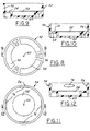
- FIG. 7 is a bottom plan view of the container body in FIGS. 5-6;
- FIG. 8 is a bottom plan view of the atmospheric vent cup in the container of FIGS. 5-6;
- FIG. 9 is a section view taken substantially along the line 9-9 in FIG. 8;
- FIG. 10 is a sectional view similar to that of FIG. 9 but showing a modified base cup;
- FIG. 11 is a top plan view of an atmospheric vent base cup in accordance with yet another embodiment of the invention;
- FIG. 12 is a sectional view taken substantially along the line 12-12 in FIG. 11;
- FIGS. 13-16 are top plan views of atmospheric vent valve disks in accordance with respective modified embodiments of the invention; and
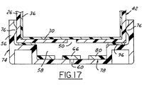
- FIG. 17 is a fragmentary sectional view of a package in accordance with another embodiment of the invention.
-
- FIG. 1 illustrates a
liquid dispensing package 20 in accordance with one presently preferred embodiment of the invention as comprising acontainer 22 and adispensing closure 24. Referring to FIGS. 1-4,container 22 includes anouter shell 26 having a flexibleresilient sidewall 28, abase wall 30 and afinish 32 surrounding and defining a mouth that forms an outlet opening from the container interior. Finish 32 has one or more external threads orbeads 34 to whichclosure 24 is secured. An inner bag-shaped liner 36 is disposed withinouter shell 26.Liner 36 is continuous throughout the interior offinish 32,sidewall 28 andbottom wall 30, being open at the container mouth for dispensing product.Liner 36 is unattached tosidewall 28 andbottom wall 30, and is collapsible with respect to the outer shell for dispensing product from within the liner. Avent opening 38 is formed inbottom wall 30 ofouter shell 26,inner liner 36 being continuous over vent opening 38.Opening 38 preferably is centered incontainer bottom 30, as shown in FIG. 4.Container 22, includingshell 26 andliner 36, preferably are formed in a plastic extrusion blow molding operation as described in above-noted U.S. Patent 6,083,450, the disclosure of which is incorporated herein by reference. Shell 26 and/orliner 36 each may be of monolayer or multi-layer construction. At least the outer layer ofliner 36 preferably is of a plastic material that is incompatible with the plastic material of the inner surface ofshell 26 so thatliner 36 is readily separated fromshell 26 as product is dispensed from within the container. - In one presently preferred embodiment of the invention,
outer shell 26 includes an outer layer of LDPE, MDPE, HDPE or polypropylene, and an inner layer of polyethylene, HDPE and/or process regrind.Inner liner 36 includes an outer layer of EVOH or virgin nylon, and an inner layer of LLDPE or LPDE. In non-health-care applications, an adhesive in the amount of about 5% to 10% by weight can be mixed with the inner layer of the liner. In health-care applications, the adhesive may be provided as a separate layer between the inner and outer liner layers. See U.S. application Serial No. 09/287,934 filed April 7, 1999, the disclosure of which is incorporated herein by reference. - In accordance with one aspect of the present invention, in the embodiment of FIGS. 1-4, vent opening 38 in
base wall 30 ofshell 26 is a small orifice-size opening. That is, opening 38 is sufficiently small to prevent rapid egress of air through the opening in response to squeezing ofcontainer sidewall 28. In this way, the forces of squeezingsidewall 28 are primarily directed to squeezingliner 36 by compressing the air volume between the liner and the shell, and to dispensing product from within the liner through the dispensing opening ofclosure 24. If the sidewall squeezing forces remain constant, the air within the volume betweenshell 26 andliner 36 will eventually flow through opening 38 sufficiently that squeezing forces are no longer applied to the liner. When the container sidewall is released, air will slowly flow back intoshell 26, betweenliner 36 and the inside surface of the shell, through small orifice-size opening 38.Package 20 is particularly useful for infrequent dispensing of product in droplet form, such as eye drops. Other applications include dispensing of liquid product in the form of a mist, a spray or a stream.Closure 24 has a dispensing opening that is sized to dispense liquid from within the package in droplet, spray or stream form, as desired.Closure 24 may comprise a dispensing closure as illustrated in U.S. Patent 6,325,253, for example. In this embodiment of the invention, opening 38 preferably has a size in the range of about 0.0007 to 0.003 square inch. Arectangular opening 38 preferably has a length of about 0.125 inch, and a width of about 0.006 to 0.008 inch. Acircular opening 38 preferably has a diameter of about 0.010 to 0.060 inch, and more preferably about 0.032 to 0.060 inch. - FIG. 5 illustrates a dispensing
package 40 in accordance with another aspect of the invention as comprising acontainer 42 and aclosure 44 secured over thefinish 45 of the container.Container 42 includes a container body having anouter shell 26 and an inner bag-shapedliner 36, as in the embodiment of FIGS. 1-4. Again, the outer shell and/or the inner liner each may be of either monolayer or multilayer construction, for example employing materials discussed above in connection with FIGS. 1-4.Shell 26 has alower end 46 formed by a cylindrical wall portion of reduced diameter as compared with the body of the shell.Lower end 46 is coaxial withbody 26 and finish 45, forming an axially downwardly facing circumferentiallycontinuous shoulder 48. (Directional words such as "upwardly" and "downwardly" are employed by way of description and not limitation with respect to the upright orientation of the packages illustrated in the drawings. Directional words such as "radially" and "laterally" are employed by way of description and not limitation with respect to the central axis of the container finish. All dimensions are nominal and are given by way of example.) Avent opening 50 is formed inbottom wall 30 ofcontainer shell 26. The container shell and liner may extrusion blow molded, and an elongated slot-shapedvent opening 50 may be formed as described above-referenced U.S. Patent 6,083,450. Abase 52 is secured tolower portion 46 ofcontainer body 42.Base 52 includes aflat deck 54 having an annularperipheral wall 56 that is telescopically received overportion 46 of the container sidewall withdeck 54 in abutment withbase wall 30 ofouter shell 26. A recessedvalve pocket 58 is centrally disposed indeck 54, extending away from the upper end of the base that is received over the container body. Anopening 60 is centrally disposed in the flat bottom wall ofpocket 58.Opening 60 has a diameter of 0.031 inch in one presently preferred but exemplary embodiment of the invention. Changing the size ofopening 60 will control how rapidlyouter shell 26 andsidewall 28 return to their normal or pre-squeezed geometries. For slower recovery, a smaller diameter opening 60 can be used, as small as 0.010 inch diameter. - A
valve disk 64 is disposed withinvalve pocket 58. In the embodiment of FIGS. 5-7,valve disk 64 is loosely received inpocket 58 for bodily movement with respect to ventopening 60.Valve disk 64 is circular in geometry, having an imperforatecentral portion 66 of sufficient diameter to cover and close vent opening 60 inpocket 58, and having a plurality ofarcuate openings 68 aroundcentral portion 66.Valve disk 64 is retained withinpocket 58 by reason of the fact that the upper end of the pocket is closed bybase wall 30 ofcontainer shell 26.Base 52 may be spun-welded onto the lower end of the container shell, or may be secured to the lower end of the container shell by any other suitable mechanism such as laser welding or adhesive. In use,valve disk 64 is loosely received withinpocket 58 ofbase 52, andbase 52 is secured overlower portion 46 ofcontainer 42. That is,disk 64 is free floating inpocket 58 and not physically attached tobase 52 in this embodiment.Closure 44, which may again be as illustrated in U.S. Patent 6,325,253, is configured to dispense liquid in droplets, spray or stream whenpackage 40 is inverted and the container sidewall is squeezed. When the sidewall is squeezed, the pressure of air betweenliner 36 andshell 26 urgesvalve disk 64 against the base ofpocket 58 so thatcentral portion 66 ofdisk 64 covers and closes opening 60 inpocket 58. Squeezing forces on the container sidewall are thus applied to the liner to dispense product within the liner throughclosure 44. When squeezing pressure is released, the resulting negative (subatmospheric) air pressure in the volume betweenshell 26 andliner 36 drawsvalve disk 64 away from the bottom wall ofpocket 58 so that air entersopening 60 and flows througharcuate passages 68 andopening 50 in the bottom wall ofshell 26 into the volume between the shell and the liner. - FIG. 10 illustrates a modified base 70. In FIG. 10 (and FIGS. 11-16), reference numerals identical to those employed in connection with FIGS. 1-9 indicate identical or related components. Base 70 is similar to base 52 (FIGS. 5-9), but additionally includes an
annular shoulder 72 that extends upwardly fromdeck 54 surroundingpocket 58.Shoulder 72 functions as an energy director when spin welding base 70 to thebottom wall 30 of container 42 (FIGS. 5-6). FIGS, 11-12 illustrate a base 74 having orthogonally positionedchordal beads 76 on the inside diameter ofperipheral wall 56.Beads 76 may be received by snap fit in a corresponding channel around the lower end of the container outer shell to retain the base cup on the container. - FIG. 13 illustrates a modified
valve disk 78, in whichcentral portion 66 is mounted within anannular periphery 80 by a series of angularly spaced axially flexible and resilient S-shapedspokes 82.Spokes 82 serve the dual functions of movably mountingcenter portion 66 withinperiphery 80, and providingspaces 84 between the spokes for passage of air between base opening 60 (FIGS. 5-6 and 8-9) and outer shell vent slot 50 (FIGS. 5 and 7). FIG. 14 shows a valve disk 86 in whichcentral portion 66 is mounted withinperiphery 80 by two S-shapedspokes 82, rather than three spokes as in the embodiment of FIG. 13. FIG. 15 illustrates avalve disk 88, in whichcentral portion 66 is mounted withinperiphery 80 by four S-shapedspokes 82. FIG. 16 illustrates avalve disk 90, which is similar tovalve disk 78 in FIG. 13 except that the S-shapedspokes 92 in FIG. 16 are wider than those in FIG. 13.Valve disks - FIG. 15 illustrates a package 94 that includes a container 42 (FIGS. 5-7), a base 74 (FIGS. 11-12), and a valve disk 78 (FIG. 13, or 86 in FIG. 14, or 88 in FIG. 15 or 90 in FIG. 16). A
thin gasket 96 is positioned betweendisk 54 ofbase 42 andbottom wall 30 ofcontainer 42.Gasket 96 is preferably of soft plastic material such as polyethylene, and provides an area for laser-weld securement of the base up to the container.Peripheral portion 80 ofvalve disk 78 is secured to the base against the bottom wall of the valve pocket, whilecentral portion 66 is free to move with respect to ventopening 60 as previously described.Beads 76 in the base function for temporary retention and centering of the base prior to welding. - There has thus been disclosed a package for dispensing a liquid product that fully satisfies all of the objects and aims previously set forth. The invention has been disclosed in conjunction with two presently preferred embodiments of the invention, and a number of modifications and variations have been discussed. Other modifications and variations will readily suggest themselves to persons of ordinary skill in the art. The invention is intended to embrace all such modifications and variations as fall within the spirit and broad scope of the appended claims.
Claims (17)
- A package for dispensing a liquid product, which comprises:an outer shell having a flexible resilient sidewall, a base wall and a finish surrounding an outlet opening,an inner liner disposed within said outer shell, said inner liner being unattached to said sidewall and said base wall of said outer shell and being collapsible with respect to said outer shell to dispense product within said liner,a dispensing structure secured to said finish, andan open orifice in said base wall of said outer shell, said open orifice being sized to prevent rapid egress of air through said orifice in response to squeezing of said sidewall so that pressure on said inner liner from squeezing said sidewall forces product within said liner out of said outlet opening and said structure, said orifice being sized to permit slow ingress of ambient air into said shell in response to release of said sidewall to permit said sidewall to return to its unsqueezed configuration.
- The package set forth in claim 1 wherein said open orifice has a size in the range of 0.0007 to 0.003 square inch.
- The package set forth in claim 2 wherein said open orifice is rectangular and has a size of about 0.125 inch by 0.006 to 0.008 inch.
- The package set forth in claim 2 wherein said open orifice is circular and has a diameter of 0.010 to 0.060 inch.
- The package set forth in any preceding claim wherein said dispensing structure comprises a closure secured to said finish, said closure having an outlet opening constructed to dispense the product in drops when said package is inverted and said sidewall is squeezed.
- A package according to any preceding claim for dispensing a liquid product, which comprises:an outer shell having a flexible resilient sidewall, a base wall and a finish surrounding an outlet opening,an inner liner disposed within said outer shell, said inner liner being unattached to said sidewall and said base wall of said outer shell and being collapsible with respect to said outer shell to dispense product within said liner,a dispensing closure secured to said finish, including a dispensing opening for dispensing of product from within said liner when said package is inverted and said shell sidewall is squeezed, andan open orifice in said base wall of said outer shell, said open orifice being sized to prevent rapid egress of air through said orifice in response to squeezing of said sidewall so that pressure on said inner liner from squeezing said sidewall forces product within said liner out of said outlet opening and said dispensing opening, said orifice being sized to permit slow ingress of ambient air into said shell in response to release of said sidewall to permit said sidewall to return to its unsqueezed configuration.
- A package for dispensing a liquid product, which comprises:an outer shell having a flexible resilient sidewall, a base wall, a finish surrounding an outlet opening, and an opening in said base wall,an inner liner disposed within said outer shell, said inner liner being unattached to said sidewall and said base wall of said outer shell and being collapsible with respect to said outer shell to dispense product within said liner,a dispensing structure secured to said finish, andan atmospheric valve assembly comprising a base secured over said base wall of said outer shell, a valve pocket within said base having an atmospheric vent opening, and a valve disk in said valve pocket for selectively opening and closing said vent opening in response to pressure of air between said outer shell on said inner liner.
- The package set forth in claim 7 wherein said valve disk is loosely received in said valve pocket for movement as a unit with respect to said vent opening.
- The package set forth in claim 7 wherein said valve disk includes a periphery secured to said base within said valve pocket, a central portion overlying said vent opening, and a plurality of resilient spokes interconnecting said central portion with said peripheral portion while permitting movement of said central portion with respect to said peripheral portion and said vent opening.
- The package set forth in claim 7 wherein said vent opening is centrally disposed in said pocket, and wherein said valve disk has a solid central portion for covering said vent opening and a peripheral portion with arcuate openings for permitting passage of air when said valve disk uncovers said vent opening.
- The package set forth in claim 10 wherein said disk is flat and of uniform thickness, and central portion is connected to said peripheral portion by spokes, spaces between said spokes forming said arcuate openings.
- The package set forth in any claim preceding wherein said dispensing structure comprises a closure secured to said finish, said closure having an outlet opening constructed to dispense the product in drops when said package is inverted and said sidewall is squeezed.
- A package for dispensing a liquid product, which comprises:an outer shell having a flexible resilient sidewall, a base wall, a finish surrounding an outlet opening, and an opening centrally disposed in said base wall,an inner liner disposed within said outer shell, said inner liner being unattached to said sidewall and said base wall of said outer shell, and being collapsible with respect to said outer shell to dispense product within said liner,a dispensing closure secured to said finish, including a dispensing opening for dispensing product from within said liner when said package is inverted and said shell sidewall is squeezed, andan atmospheric valve assembly comprising a base secured over said base wall of said outer shell, a valve pocket within said base having a bottom wall with an atmospheric vent opening, and a valve disk in said valve pocket, said valve disk being flat and of uniform thickness, having a central portion for covering said vent opening, a peripheral portion secured within said valve pocket against said bottom wall, and a plurality of flexibly resilient spokes interconnecting said central and peripheral portions to permit movement of said central portion with respect to said peripheral portion and said vent opening, spaces between said spokes permitting passage of air from said vent opening in said base wall when said disk is paced from said vent opening.
- The package set forth in claim 11 or 13 wherein said spokes are S-shaped.
- The package set forth in any claim preceding wherein said base has a peripheral wall telescopically received over a lower portion of said shell.
- The package set forth in claim 15 wherein said lower portion of said shell has a reduced diameter for receiving said peripheral wall of said base.
- The package set forth in claim 16 wherein said base is welded to said lower portion of said shell.
Applications Claiming Priority (2)
| Application Number | Priority Date | Filing Date | Title |
|---|---|---|---|
| US10/105,730 US6719173B2 (en) | 2002-03-25 | 2002-03-25 | Multilayer container package for dispensing a liquid product |
| US105730 | 2002-03-25 |
Publications (2)
| Publication Number | Publication Date |
|---|---|
| EP1348642A2 true EP1348642A2 (en) | 2003-10-01 |
| EP1348642A3 EP1348642A3 (en) | 2004-07-28 |
Family
ID=27804339
Family Applications (1)
| Application Number | Title | Priority Date | Filing Date |
|---|---|---|---|
| EP03251826A Withdrawn EP1348642A3 (en) | 2002-03-25 | 2003-03-24 | Multilayer container package for dispensing a liquid product |
Country Status (5)
| Country | Link |
|---|---|
| US (3) | US6719173B2 (en) |
| EP (1) | EP1348642A3 (en) |
| JP (1) | JP2003312730A (en) |
| CA (1) | CA2423366A1 (en) |
| MX (1) | MXPA03002508A (en) |
Cited By (3)
| Publication number | Priority date | Publication date | Assignee | Title |
|---|---|---|---|---|
| EP2172400A1 (en) * | 2007-06-29 | 2010-04-07 | Yoshino Kogyosyo Co., Ltd. | Double container of synthetic resin by direct blow molding method |
| KR20170084090A (en) * | 2014-11-18 | 2017-07-19 | 가부시끼가이샤 헤이와 가가꾸 고교쇼 | Double container for high-viscosity liquid |
| US10968032B2 (en) | 2015-10-07 | 2021-04-06 | Conopeo, Inc. | Refill device for dispensing a liquid product |
Families Citing this family (21)
| Publication number | Priority date | Publication date | Assignee | Title |
|---|---|---|---|---|
| US6719173B2 (en) * | 2002-03-25 | 2004-04-13 | Owens-Brockway Plastic Products Inc. | Multilayer container package for dispensing a liquid product |
| KR100921133B1 (en) | 2002-04-30 | 2009-10-12 | 가부시키가이샤 요시노 고교쇼 | Pouring container |
| US7308991B2 (en) * | 2003-11-17 | 2007-12-18 | Advanced Technology Materials, Inc. | Blown bottle with intrinsic liner |
| US20060065132A1 (en) * | 2004-09-27 | 2006-03-30 | Conopco, Inc., D/B/A Unilever Foodsolutions | Combined food product and package |
| US7410106B2 (en) * | 2005-02-08 | 2008-08-12 | 3M Innovative Properties Company | Pressurized liquid supply assembly |
| ES2326754T3 (en) | 2006-03-20 | 2009-10-19 | Selig Sealing Products, Inc. | CLOSURE LAMINATE FOR CONTAINERS. |
| US8061918B2 (en) * | 2006-04-13 | 2011-11-22 | S.C. Johnson & Son, Inc. | Heated flowable product dispenser |
| KR101571575B1 (en) * | 2007-12-07 | 2015-11-24 | 어드밴스드 테크놀러지 머티리얼즈, 인코포레이티드 | blow molded liner for overpack container and method of manufacturing the same |
| US20120124942A1 (en) * | 2009-03-03 | 2012-05-24 | Gidi Shani | Volume adjusted preservation containment system |
| US20110108516A1 (en) * | 2009-04-07 | 2011-05-12 | Mcfarland James | Ergonomic sports bottle having disposable liner |
| EP2669213A1 (en) | 2009-07-09 | 2013-12-04 | Advanced Technology Materials, Inc. | Liner-based storage system |
| JP5450264B2 (en) * | 2010-05-31 | 2014-03-26 | 株式会社吉野工業所 | Dispensing container |
| WO2012051093A2 (en) * | 2010-10-11 | 2012-04-19 | Advanced Technology Materials, Inc. | Substantially rigid collapsible liner, container and/or liner for replacing glass bottles, and enhanced flexible liners |
| WO2012071370A2 (en) | 2010-11-23 | 2012-05-31 | Advanced Technology Materials, Inc. | Liner-based dispenser |
| US10894340B2 (en) | 2010-12-17 | 2021-01-19 | Dispensing Technologies B.V. | Preforms for flair applications |
| WO2012118527A1 (en) | 2011-03-01 | 2012-09-07 | Advanced Technology Materials, Inc. | Nested blow molded liner and overpack and methods of making same |
| US9221204B2 (en) * | 2013-03-14 | 2015-12-29 | Kortec, Inc. | Techniques to mold parts with injection-formed aperture in gate area |
| US9815597B2 (en) | 2013-05-20 | 2017-11-14 | Jezekiel Ben-Arie | Twist based dispenser |
| US9833799B2 (en) | 2014-05-13 | 2017-12-05 | Berry Plastics Corporation | Container closure with product-discharge control system |
| JP6421458B2 (en) * | 2014-05-29 | 2018-11-14 | キョーラク株式会社 | Delamination container |
| WO2019050979A1 (en) * | 2017-09-08 | 2019-03-14 | Altenburg Krysten | Modeling clay container |
Citations (6)
| Publication number | Priority date | Publication date | Assignee | Title |
|---|---|---|---|---|
| EP0305003A1 (en) * | 1987-08-28 | 1989-03-01 | The Procter & Gamble Company | Resilient squeeze bottle package for dispensing viscous products without belching |
| US5373967A (en) * | 1993-12-07 | 1994-12-20 | The Procter & Gamble Company | Squeezebottle dispenser having a channeled vent valve |
| US5419465A (en) * | 1994-09-26 | 1995-05-30 | Schroeder; Jeffrey J. | Automatic volume dispensing fluid container |
| EP0829432A1 (en) * | 1996-09-16 | 1998-03-18 | L'oreal | Liquid or pasty product dispenser |
| EP1153845A1 (en) * | 1999-11-19 | 2001-11-14 | Taisei Kako Co., Ltd. | Delivery container |
| US6325253B1 (en) * | 2001-02-02 | 2001-12-04 | Owens-Illinois Closure Inc. | Self-closing fluid dispensing closure |
Family Cites Families (26)
| Publication number | Priority date | Publication date | Assignee | Title |
|---|---|---|---|---|
| US2715980A (en) | 1950-10-09 | 1955-08-23 | Leo M Harvey | Liquid handling dispenser |
| US4154366A (en) | 1977-01-31 | 1979-05-15 | Acres Alexander D | Dispensing container |
| US4295582A (en) | 1979-08-09 | 1981-10-20 | Acres Alexander D | Dispensing container with improved air valve |
| US4657151A (en) | 1984-04-12 | 1987-04-14 | Baxter Travenol Laboratories, Inc. | Container such as a nursing container, with flexible liner |
| US4760937A (en) | 1986-06-16 | 1988-08-02 | Evezich Paul D | Squeezable device for ejecting retained materials |
| US4909416A (en) | 1986-06-16 | 1990-03-20 | Evezich Paul D | Device for containing and dispensing flowable materials |
| AU639674B2 (en) * | 1988-10-24 | 1993-08-05 | Asahi Tec Corporation | Spinning molding process, spinning molding apparatus, spinning molding raw material, spinning molding process of vehicle wheel, and spinning molding apparatus of vehicle wheel |
| US4979631A (en) | 1988-11-14 | 1990-12-25 | Continental Pet Technologies, Inc. | Vented recyclable multilayer barrier container |
| US5012956A (en) | 1989-08-07 | 1991-05-07 | Stoody William R | Squeeze bottle with bag, dispensing system |
| US5242085A (en) * | 1990-12-17 | 1993-09-07 | The Coca-Cola Company | Liquid container system |
| BE1004298A3 (en) | 1991-01-04 | 1992-10-27 | Piarrat Jeffrey | Packaging distributor for product paste. |
| US5125534A (en) * | 1991-01-14 | 1992-06-30 | Rose Barry L | Beverage flavoring and dispensing apparatus and method of construction |
| US5301838A (en) | 1991-01-23 | 1994-04-12 | Continental Pet Technologies, Inc. | Multilayer bottle with separable inner layer and method for forming same |
| CA2110411A1 (en) | 1991-06-07 | 1992-12-10 | Leane Kristine Davis | Resilient squeeze bottle employing air check valve |
| AU666324B2 (en) | 1991-08-05 | 1996-02-08 | Yoshino Kogyosho Co., Ltd. | Bottle of laminate structure and method of making said bottle |
| JPH0554345U (en) * | 1991-12-20 | 1993-07-20 | サンスター株式会社 | Viscous liquid dispensing container |
| US5353930A (en) * | 1993-08-06 | 1994-10-11 | Carr Metal Products, Inc. | Vacuum-formed enclosure with vacuum-formed apertures |
| US5487490A (en) | 1994-03-30 | 1996-01-30 | Codev Corp. | Product dispenser with air displacement device |
| US5680966A (en) | 1994-04-06 | 1997-10-28 | Reflex Packaging Group | Squeeze dispenser having refill cartridge |
| KR100338994B1 (en) | 1995-03-10 | 2002-06-01 | 요시노 쇼이치로 | Separable laminated container and associated technology |
| US5687882A (en) | 1995-05-31 | 1997-11-18 | Containaire Incorporated | Flexible dispenser with bladder |
| US5699920A (en) | 1995-08-21 | 1997-12-23 | Ida; Frank | Pump nurser for expelling air from disposable liners |
| CA2230768C (en) | 1997-02-28 | 2007-02-13 | John W. Safian | Multilayer container package |
| JP4485627B2 (en) * | 1999-10-08 | 2010-06-23 | 大成化工株式会社 | Laminated peeling bottle and pump container |
| US6446822B1 (en) * | 2000-09-28 | 2002-09-10 | Gerber Products Company | Nursing bottle |
| US6719173B2 (en) * | 2002-03-25 | 2004-04-13 | Owens-Brockway Plastic Products Inc. | Multilayer container package for dispensing a liquid product |
-
2002
- 2002-03-25 US US10/105,730 patent/US6719173B2/en not_active Expired - Fee Related
-
2003
- 2003-03-20 JP JP2003120683A patent/JP2003312730A/en active Pending
- 2003-03-20 MX MXPA03002508A patent/MXPA03002508A/en unknown
- 2003-03-24 EP EP03251826A patent/EP1348642A3/en not_active Withdrawn
- 2003-03-24 CA CA002423366A patent/CA2423366A1/en not_active Abandoned
-
2004
- 2004-01-05 US US10/751,367 patent/US20040134934A1/en not_active Abandoned
-
2007
- 2007-07-19 US US11/826,970 patent/US20070262093A1/en not_active Abandoned
Patent Citations (6)
| Publication number | Priority date | Publication date | Assignee | Title |
|---|---|---|---|---|
| EP0305003A1 (en) * | 1987-08-28 | 1989-03-01 | The Procter & Gamble Company | Resilient squeeze bottle package for dispensing viscous products without belching |
| US5373967A (en) * | 1993-12-07 | 1994-12-20 | The Procter & Gamble Company | Squeezebottle dispenser having a channeled vent valve |
| US5419465A (en) * | 1994-09-26 | 1995-05-30 | Schroeder; Jeffrey J. | Automatic volume dispensing fluid container |
| EP0829432A1 (en) * | 1996-09-16 | 1998-03-18 | L'oreal | Liquid or pasty product dispenser |
| EP1153845A1 (en) * | 1999-11-19 | 2001-11-14 | Taisei Kako Co., Ltd. | Delivery container |
| US6325253B1 (en) * | 2001-02-02 | 2001-12-04 | Owens-Illinois Closure Inc. | Self-closing fluid dispensing closure |
Cited By (8)
| Publication number | Priority date | Publication date | Assignee | Title |
|---|---|---|---|---|
| EP2172400A1 (en) * | 2007-06-29 | 2010-04-07 | Yoshino Kogyosyo Co., Ltd. | Double container of synthetic resin by direct blow molding method |
| EP2172400A4 (en) * | 2007-06-29 | 2010-07-14 | Yoshino Kogyosho Co Ltd | Double container of synthetic resin by direct blow molding method |
| KR20170084090A (en) * | 2014-11-18 | 2017-07-19 | 가부시끼가이샤 헤이와 가가꾸 고교쇼 | Double container for high-viscosity liquid |
| CN107000897A (en) * | 2014-11-18 | 2017-08-01 | 株式会社平和化学工业所 | High viscosity liquid double container |
| EP3222547A4 (en) * | 2014-11-18 | 2018-05-09 | Heiwa Kagaku Industry Co., Ltd. | Double-walled container for highly viscous liquid |
| CN107000897B (en) * | 2014-11-18 | 2019-09-17 | 株式会社平和化学工业所 | High viscosity liquid double container |
| CN107000897B9 (en) * | 2014-11-18 | 2019-11-15 | 株式会社平和化学工业所 | High viscosity liquid double container |
| US10968032B2 (en) | 2015-10-07 | 2021-04-06 | Conopeo, Inc. | Refill device for dispensing a liquid product |
Also Published As
| Publication number | Publication date |
|---|---|
| US6719173B2 (en) | 2004-04-13 |
| MXPA03002508A (en) | 2004-08-11 |
| CA2423366A1 (en) | 2003-09-25 |
| US20070262093A1 (en) | 2007-11-15 |
| JP2003312730A (en) | 2003-11-06 |
| US20030178445A1 (en) | 2003-09-25 |
| US20040134934A1 (en) | 2004-07-15 |
| EP1348642A3 (en) | 2004-07-28 |
Similar Documents
| Publication | Publication Date | Title |
|---|---|---|
| US20070262093A1 (en) | Multilayer container package for dispensing a liquid product | |
| EP1228975B1 (en) | Self-closing fluid dispensing closure | |
| US7770762B2 (en) | Deformable flexible pouch and device for packaging and dispensing fluid products | |
| CZ200292A3 (en) | Valved proportioning system for several dosing streams | |
| EP1320416B1 (en) | Aerosol spray dispenser | |
| US20070158292A1 (en) | Vented container | |
| US5143263A (en) | Spray dispenser having a non-use storage recess for a discharge tube | |
| CA2550183A1 (en) | Closure with selectable dispensing orifices | |
| US20070284397A1 (en) | Valve-controlled dispensing closure | |
| MX2014010479A (en) | Dispensing valve. | |
| JPH07502239A (en) | Package with replaceable inner container with large integrally molded attachment area | |
| EP3536633B1 (en) | Multi-piece valve stem for aerosols | |
| WO2010036645A1 (en) | Baffled dispensing closure | |
| US5224630A (en) | Pressurized container having double walls and safety venting feature | |
| US20050218164A1 (en) | Actuator cap for aerosol containers | |
| US20200270026A1 (en) | Vented pour spout | |
| CA2415870A1 (en) | Fluid dispensing valve and method of use | |
| AU2001276897A1 (en) | Fluid dispensing valve and method of use | |
| JP2017214110A (en) | Discharge container | |
| US7891518B2 (en) | Wide-dispersal package and cap assembly | |
| EP2949601B1 (en) | Elastic dispenser of bag-in-bottle type | |
| JP7471750B2 (en) | Double container | |
| JP7285432B2 (en) | double container | |
| EP1442994A1 (en) | Dispensing closure | |
| JP2589777Y2 (en) | Aerosol device |
Legal Events
| Date | Code | Title | Description |
|---|---|---|---|
| PUAI | Public reference made under article 153(3) epc to a published international application that has entered the european phase |
Free format text: ORIGINAL CODE: 0009012 |
|
| AK | Designated contracting states |
Kind code of ref document: A2 Designated state(s): AT BE BG CH CY CZ DE DK EE ES FI FR GB GR HU IE IT LI LU MC NL PT RO SE SI SK TR |
|
| AX | Request for extension of the european patent |
Extension state: AL LT LV MK |
|
| PUAL | Search report despatched |
Free format text: ORIGINAL CODE: 0009013 |
|
| AK | Designated contracting states |
Kind code of ref document: A3 Designated state(s): AT BE BG CH CY CZ DE DK EE ES FI FR GB GR HU IE IT LI LU MC NL PT RO SE SI SK TR |
|
| AX | Request for extension of the european patent |
Extension state: AL LT LV MK |
|
| 17P | Request for examination filed |
Effective date: 20050111 |
|
| AKX | Designation fees paid |
Designated state(s): AT BE BG CH CY CZ DE DK EE ES FI FR GB GR HU IE IT LI LU MC NL PT RO SE SI SK TR |
|
| RAP1 | Party data changed (applicant data changed or rights of an application transferred) |
Owner name: GRAHAM PACKAGING PLASTIC PRODUCTS INC. |
|
| 17Q | First examination report despatched |
Effective date: 20070323 |
|
| STAA | Information on the status of an ep patent application or granted ep patent |
Free format text: STATUS: THE APPLICATION IS DEEMED TO BE WITHDRAWN |
|
| 18D | Application deemed to be withdrawn |
Effective date: 20091001 |