EP1350932A2 - Exhaust emission control system of a diesel engine and method therefore - Google Patents
Exhaust emission control system of a diesel engine and method therefore Download PDFInfo
- Publication number
- EP1350932A2 EP1350932A2 EP03007047A EP03007047A EP1350932A2 EP 1350932 A2 EP1350932 A2 EP 1350932A2 EP 03007047 A EP03007047 A EP 03007047A EP 03007047 A EP03007047 A EP 03007047A EP 1350932 A2 EP1350932 A2 EP 1350932A2
- Authority
- EP
- European Patent Office
- Prior art keywords
- exhaust gas
- temperature
- catalytic converter
- excess air
- air ratio
- Prior art date
- Legal status (The legal status is an assumption and is not a legal conclusion. Google has not performed a legal analysis and makes no representation as to the accuracy of the status listed.)
- Granted
Links
Images


Classifications
-
- F—MECHANICAL ENGINEERING; LIGHTING; HEATING; WEAPONS; BLASTING
- F02—COMBUSTION ENGINES; HOT-GAS OR COMBUSTION-PRODUCT ENGINE PLANTS
- F02D—CONTROLLING COMBUSTION ENGINES
- F02D41/00—Electrical control of supply of combustible mixture or its constituents
- F02D41/0025—Controlling engines characterised by use of non-liquid fuels, pluralities of fuels, or non-fuel substances added to the combustible mixtures
- F02D41/0047—Controlling exhaust gas recirculation [EGR]
- F02D41/005—Controlling exhaust gas recirculation [EGR] according to engine operating conditions
- F02D41/0055—Special engine operating conditions, e.g. for regeneration of exhaust gas treatment apparatus
-
- F—MECHANICAL ENGINEERING; LIGHTING; HEATING; WEAPONS; BLASTING
- F01—MACHINES OR ENGINES IN GENERAL; ENGINE PLANTS IN GENERAL; STEAM ENGINES
- F01N—GAS-FLOW SILENCERS OR EXHAUST APPARATUS FOR MACHINES OR ENGINES IN GENERAL; GAS-FLOW SILENCERS OR EXHAUST APPARATUS FOR INTERNAL COMBUSTION ENGINES
- F01N13/00—Exhaust or silencing apparatus characterised by constructional features ; Exhaust or silencing apparatus, or parts thereof, having pertinent characteristics not provided for in, or of interest apart from, groups F01N1/00 - F01N5/00, F01N9/00, F01N11/00
- F01N13/009—Exhaust or silencing apparatus characterised by constructional features ; Exhaust or silencing apparatus, or parts thereof, having pertinent characteristics not provided for in, or of interest apart from, groups F01N1/00 - F01N5/00, F01N9/00, F01N11/00 having two or more separate purifying devices arranged in series
-
- F—MECHANICAL ENGINEERING; LIGHTING; HEATING; WEAPONS; BLASTING
- F01—MACHINES OR ENGINES IN GENERAL; ENGINE PLANTS IN GENERAL; STEAM ENGINES
- F01N—GAS-FLOW SILENCERS OR EXHAUST APPARATUS FOR MACHINES OR ENGINES IN GENERAL; GAS-FLOW SILENCERS OR EXHAUST APPARATUS FOR INTERNAL COMBUSTION ENGINES
- F01N3/00—Exhaust or silencing apparatus having means for purifying, rendering innocuous, or otherwise treating exhaust
- F01N3/08—Exhaust or silencing apparatus having means for purifying, rendering innocuous, or otherwise treating exhaust for rendering innocuous
- F01N3/0807—Exhaust or silencing apparatus having means for purifying, rendering innocuous, or otherwise treating exhaust for rendering innocuous by using absorbents or adsorbents
- F01N3/0814—Exhaust or silencing apparatus having means for purifying, rendering innocuous, or otherwise treating exhaust for rendering innocuous by using absorbents or adsorbents combined with catalytic converters, e.g. NOx absorption/storage reduction catalysts
-
- F—MECHANICAL ENGINEERING; LIGHTING; HEATING; WEAPONS; BLASTING
- F01—MACHINES OR ENGINES IN GENERAL; ENGINE PLANTS IN GENERAL; STEAM ENGINES
- F01N—GAS-FLOW SILENCERS OR EXHAUST APPARATUS FOR MACHINES OR ENGINES IN GENERAL; GAS-FLOW SILENCERS OR EXHAUST APPARATUS FOR INTERNAL COMBUSTION ENGINES
- F01N3/00—Exhaust or silencing apparatus having means for purifying, rendering innocuous, or otherwise treating exhaust
- F01N3/08—Exhaust or silencing apparatus having means for purifying, rendering innocuous, or otherwise treating exhaust for rendering innocuous
- F01N3/0807—Exhaust or silencing apparatus having means for purifying, rendering innocuous, or otherwise treating exhaust for rendering innocuous by using absorbents or adsorbents
- F01N3/0821—Exhaust or silencing apparatus having means for purifying, rendering innocuous, or otherwise treating exhaust for rendering innocuous by using absorbents or adsorbents combined with particulate filters
-
- F—MECHANICAL ENGINEERING; LIGHTING; HEATING; WEAPONS; BLASTING
- F01—MACHINES OR ENGINES IN GENERAL; ENGINE PLANTS IN GENERAL; STEAM ENGINES
- F01N—GAS-FLOW SILENCERS OR EXHAUST APPARATUS FOR MACHINES OR ENGINES IN GENERAL; GAS-FLOW SILENCERS OR EXHAUST APPARATUS FOR INTERNAL COMBUSTION ENGINES
- F01N3/00—Exhaust or silencing apparatus having means for purifying, rendering innocuous, or otherwise treating exhaust
- F01N3/08—Exhaust or silencing apparatus having means for purifying, rendering innocuous, or otherwise treating exhaust for rendering innocuous
- F01N3/0807—Exhaust or silencing apparatus having means for purifying, rendering innocuous, or otherwise treating exhaust for rendering innocuous by using absorbents or adsorbents
- F01N3/0828—Exhaust or silencing apparatus having means for purifying, rendering innocuous, or otherwise treating exhaust for rendering innocuous by using absorbents or adsorbents characterised by the absorbed or adsorbed substances
- F01N3/0835—Hydrocarbons
-
- F—MECHANICAL ENGINEERING; LIGHTING; HEATING; WEAPONS; BLASTING
- F01—MACHINES OR ENGINES IN GENERAL; ENGINE PLANTS IN GENERAL; STEAM ENGINES
- F01N—GAS-FLOW SILENCERS OR EXHAUST APPARATUS FOR MACHINES OR ENGINES IN GENERAL; GAS-FLOW SILENCERS OR EXHAUST APPARATUS FOR INTERNAL COMBUSTION ENGINES
- F01N3/00—Exhaust or silencing apparatus having means for purifying, rendering innocuous, or otherwise treating exhaust
- F01N3/08—Exhaust or silencing apparatus having means for purifying, rendering innocuous, or otherwise treating exhaust for rendering innocuous
- F01N3/0807—Exhaust or silencing apparatus having means for purifying, rendering innocuous, or otherwise treating exhaust for rendering innocuous by using absorbents or adsorbents
- F01N3/0828—Exhaust or silencing apparatus having means for purifying, rendering innocuous, or otherwise treating exhaust for rendering innocuous by using absorbents or adsorbents characterised by the absorbed or adsorbed substances
- F01N3/0842—Nitrogen oxides
-
- F—MECHANICAL ENGINEERING; LIGHTING; HEATING; WEAPONS; BLASTING
- F01—MACHINES OR ENGINES IN GENERAL; ENGINE PLANTS IN GENERAL; STEAM ENGINES
- F01N—GAS-FLOW SILENCERS OR EXHAUST APPARATUS FOR MACHINES OR ENGINES IN GENERAL; GAS-FLOW SILENCERS OR EXHAUST APPARATUS FOR INTERNAL COMBUSTION ENGINES
- F01N3/00—Exhaust or silencing apparatus having means for purifying, rendering innocuous, or otherwise treating exhaust
- F01N3/08—Exhaust or silencing apparatus having means for purifying, rendering innocuous, or otherwise treating exhaust for rendering innocuous
- F01N3/0807—Exhaust or silencing apparatus having means for purifying, rendering innocuous, or otherwise treating exhaust for rendering innocuous by using absorbents or adsorbents
- F01N3/0871—Regulation of absorbents or adsorbents, e.g. purging
- F01N3/0885—Regeneration of deteriorated absorbents or adsorbents, e.g. desulfurization of NOx traps
-
- F—MECHANICAL ENGINEERING; LIGHTING; HEATING; WEAPONS; BLASTING
- F01—MACHINES OR ENGINES IN GENERAL; ENGINE PLANTS IN GENERAL; STEAM ENGINES
- F01N—GAS-FLOW SILENCERS OR EXHAUST APPARATUS FOR MACHINES OR ENGINES IN GENERAL; GAS-FLOW SILENCERS OR EXHAUST APPARATUS FOR INTERNAL COMBUSTION ENGINES
- F01N3/00—Exhaust or silencing apparatus having means for purifying, rendering innocuous, or otherwise treating exhaust
- F01N3/08—Exhaust or silencing apparatus having means for purifying, rendering innocuous, or otherwise treating exhaust for rendering innocuous
- F01N3/10—Exhaust or silencing apparatus having means for purifying, rendering innocuous, or otherwise treating exhaust for rendering innocuous by thermal or catalytic conversion of noxious components of exhaust
- F01N3/101—Three-way catalysts
-
- F—MECHANICAL ENGINEERING; LIGHTING; HEATING; WEAPONS; BLASTING
- F02—COMBUSTION ENGINES; HOT-GAS OR COMBUSTION-PRODUCT ENGINE PLANTS
- F02D—CONTROLLING COMBUSTION ENGINES
- F02D41/00—Electrical control of supply of combustible mixture or its constituents
- F02D41/02—Circuit arrangements for generating control signals
- F02D41/021—Introducing corrections for particular conditions exterior to the engine
- F02D41/0235—Introducing corrections for particular conditions exterior to the engine in relation with the state of the exhaust gas treating apparatus
- F02D41/024—Introducing corrections for particular conditions exterior to the engine in relation with the state of the exhaust gas treating apparatus to increase temperature of the exhaust gas treating apparatus
-
- F—MECHANICAL ENGINEERING; LIGHTING; HEATING; WEAPONS; BLASTING
- F02—COMBUSTION ENGINES; HOT-GAS OR COMBUSTION-PRODUCT ENGINE PLANTS
- F02M—SUPPLYING COMBUSTION ENGINES IN GENERAL WITH COMBUSTIBLE MIXTURES OR CONSTITUENTS THEREOF
- F02M26/00—Engine-pertinent apparatus for adding exhaust gases to combustion-air, main fuel or fuel-air mixture, e.g. by exhaust gas recirculation [EGR] systems
- F02M26/02—EGR systems specially adapted for supercharged engines
- F02M26/04—EGR systems specially adapted for supercharged engines with a single turbocharger
- F02M26/05—High pressure loops, i.e. wherein recirculated exhaust gas is taken out from the exhaust system upstream of the turbine and reintroduced into the intake system downstream of the compressor
-
- F—MECHANICAL ENGINEERING; LIGHTING; HEATING; WEAPONS; BLASTING
- F01—MACHINES OR ENGINES IN GENERAL; ENGINE PLANTS IN GENERAL; STEAM ENGINES
- F01N—GAS-FLOW SILENCERS OR EXHAUST APPARATUS FOR MACHINES OR ENGINES IN GENERAL; GAS-FLOW SILENCERS OR EXHAUST APPARATUS FOR INTERNAL COMBUSTION ENGINES
- F01N2250/00—Combinations of different methods of purification
- F01N2250/02—Combinations of different methods of purification filtering and catalytic conversion
-
- F—MECHANICAL ENGINEERING; LIGHTING; HEATING; WEAPONS; BLASTING
- F01—MACHINES OR ENGINES IN GENERAL; ENGINE PLANTS IN GENERAL; STEAM ENGINES
- F01N—GAS-FLOW SILENCERS OR EXHAUST APPARATUS FOR MACHINES OR ENGINES IN GENERAL; GAS-FLOW SILENCERS OR EXHAUST APPARATUS FOR INTERNAL COMBUSTION ENGINES
- F01N2250/00—Combinations of different methods of purification
- F01N2250/12—Combinations of different methods of purification absorption or adsorption, and catalytic conversion
-
- F—MECHANICAL ENGINEERING; LIGHTING; HEATING; WEAPONS; BLASTING
- F01—MACHINES OR ENGINES IN GENERAL; ENGINE PLANTS IN GENERAL; STEAM ENGINES
- F01N—GAS-FLOW SILENCERS OR EXHAUST APPARATUS FOR MACHINES OR ENGINES IN GENERAL; GAS-FLOW SILENCERS OR EXHAUST APPARATUS FOR INTERNAL COMBUSTION ENGINES
- F01N2250/00—Combinations of different methods of purification
- F01N2250/14—Combinations of different methods of purification absorption or adsorption, and filtering
-
- F—MECHANICAL ENGINEERING; LIGHTING; HEATING; WEAPONS; BLASTING
- F01—MACHINES OR ENGINES IN GENERAL; ENGINE PLANTS IN GENERAL; STEAM ENGINES
- F01N—GAS-FLOW SILENCERS OR EXHAUST APPARATUS FOR MACHINES OR ENGINES IN GENERAL; GAS-FLOW SILENCERS OR EXHAUST APPARATUS FOR INTERNAL COMBUSTION ENGINES
- F01N2430/00—Influencing exhaust purification, e.g. starting of catalytic reaction, filter regeneration, or the like, by controlling engine operating characteristics
- F01N2430/06—Influencing exhaust purification, e.g. starting of catalytic reaction, filter regeneration, or the like, by controlling engine operating characteristics by varying fuel-air ratio, e.g. by enriching fuel-air mixture
-
- F—MECHANICAL ENGINEERING; LIGHTING; HEATING; WEAPONS; BLASTING
- F01—MACHINES OR ENGINES IN GENERAL; ENGINE PLANTS IN GENERAL; STEAM ENGINES
- F01N—GAS-FLOW SILENCERS OR EXHAUST APPARATUS FOR MACHINES OR ENGINES IN GENERAL; GAS-FLOW SILENCERS OR EXHAUST APPARATUS FOR INTERNAL COMBUSTION ENGINES
- F01N2570/00—Exhaust treating apparatus eliminating, absorbing or adsorbing specific elements or compounds
- F01N2570/12—Hydrocarbons
-
- F—MECHANICAL ENGINEERING; LIGHTING; HEATING; WEAPONS; BLASTING
- F01—MACHINES OR ENGINES IN GENERAL; ENGINE PLANTS IN GENERAL; STEAM ENGINES
- F01N—GAS-FLOW SILENCERS OR EXHAUST APPARATUS FOR MACHINES OR ENGINES IN GENERAL; GAS-FLOW SILENCERS OR EXHAUST APPARATUS FOR INTERNAL COMBUSTION ENGINES
- F01N2570/00—Exhaust treating apparatus eliminating, absorbing or adsorbing specific elements or compounds
- F01N2570/14—Nitrogen oxides
-
- F—MECHANICAL ENGINEERING; LIGHTING; HEATING; WEAPONS; BLASTING
- F02—COMBUSTION ENGINES; HOT-GAS OR COMBUSTION-PRODUCT ENGINE PLANTS
- F02B—INTERNAL-COMBUSTION PISTON ENGINES; COMBUSTION ENGINES IN GENERAL
- F02B3/00—Engines characterised by air compression and subsequent fuel addition
- F02B3/06—Engines characterised by air compression and subsequent fuel addition with compression ignition
-
- F—MECHANICAL ENGINEERING; LIGHTING; HEATING; WEAPONS; BLASTING
- F02—COMBUSTION ENGINES; HOT-GAS OR COMBUSTION-PRODUCT ENGINE PLANTS
- F02B—INTERNAL-COMBUSTION PISTON ENGINES; COMBUSTION ENGINES IN GENERAL
- F02B37/00—Engines characterised by provision of pumps driven at least for part of the time by exhaust
-
- F—MECHANICAL ENGINEERING; LIGHTING; HEATING; WEAPONS; BLASTING
- F02—COMBUSTION ENGINES; HOT-GAS OR COMBUSTION-PRODUCT ENGINE PLANTS
- F02D—CONTROLLING COMBUSTION ENGINES
- F02D2200/00—Input parameters for engine control
- F02D2200/02—Input parameters for engine control the parameters being related to the engine
- F02D2200/08—Exhaust gas treatment apparatus parameters
- F02D2200/0802—Temperature of the exhaust gas treatment apparatus
-
- F—MECHANICAL ENGINEERING; LIGHTING; HEATING; WEAPONS; BLASTING
- F02—COMBUSTION ENGINES; HOT-GAS OR COMBUSTION-PRODUCT ENGINE PLANTS
- F02D—CONTROLLING COMBUSTION ENGINES
- F02D41/00—Electrical control of supply of combustible mixture or its constituents
- F02D41/02—Circuit arrangements for generating control signals
- F02D41/021—Introducing corrections for particular conditions exterior to the engine
- F02D41/0235—Introducing corrections for particular conditions exterior to the engine in relation with the state of the exhaust gas treating apparatus
- F02D41/027—Introducing corrections for particular conditions exterior to the engine in relation with the state of the exhaust gas treating apparatus to purge or regenerate the exhaust gas treating apparatus
- F02D41/0275—Introducing corrections for particular conditions exterior to the engine in relation with the state of the exhaust gas treating apparatus to purge or regenerate the exhaust gas treating apparatus the exhaust gas treating apparatus being a NOx trap or adsorbent
-
- F—MECHANICAL ENGINEERING; LIGHTING; HEATING; WEAPONS; BLASTING
- F02—COMBUSTION ENGINES; HOT-GAS OR COMBUSTION-PRODUCT ENGINE PLANTS
- F02D—CONTROLLING COMBUSTION ENGINES
- F02D41/00—Electrical control of supply of combustible mixture or its constituents
- F02D41/02—Circuit arrangements for generating control signals
- F02D41/021—Introducing corrections for particular conditions exterior to the engine
- F02D41/0235—Introducing corrections for particular conditions exterior to the engine in relation with the state of the exhaust gas treating apparatus
- F02D41/027—Introducing corrections for particular conditions exterior to the engine in relation with the state of the exhaust gas treating apparatus to purge or regenerate the exhaust gas treating apparatus
- F02D41/029—Introducing corrections for particular conditions exterior to the engine in relation with the state of the exhaust gas treating apparatus to purge or regenerate the exhaust gas treating apparatus the exhaust gas treating apparatus being a particulate filter
-
- F—MECHANICAL ENGINEERING; LIGHTING; HEATING; WEAPONS; BLASTING
- F02—COMBUSTION ENGINES; HOT-GAS OR COMBUSTION-PRODUCT ENGINE PLANTS
- F02M—SUPPLYING COMBUSTION ENGINES IN GENERAL WITH COMBUSTIBLE MIXTURES OR CONSTITUENTS THEREOF
- F02M26/00—Engine-pertinent apparatus for adding exhaust gases to combustion-air, main fuel or fuel-air mixture, e.g. by exhaust gas recirculation [EGR] systems
- F02M26/02—EGR systems specially adapted for supercharged engines
- F02M26/09—Constructional details, e.g. structural combinations of EGR systems and supercharger systems; Arrangement of the EGR and supercharger systems with respect to the engine
- F02M26/10—Constructional details, e.g. structural combinations of EGR systems and supercharger systems; Arrangement of the EGR and supercharger systems with respect to the engine having means to increase the pressure difference between the exhaust and intake system, e.g. venturis, variable geometry turbines, check valves using pressure pulsations or throttles in the air intake or exhaust system
-
- Y—GENERAL TAGGING OF NEW TECHNOLOGICAL DEVELOPMENTS; GENERAL TAGGING OF CROSS-SECTIONAL TECHNOLOGIES SPANNING OVER SEVERAL SECTIONS OF THE IPC; TECHNICAL SUBJECTS COVERED BY FORMER USPC CROSS-REFERENCE ART COLLECTIONS [XRACs] AND DIGESTS
- Y02—TECHNOLOGIES OR APPLICATIONS FOR MITIGATION OR ADAPTATION AGAINST CLIMATE CHANGE
- Y02A—TECHNOLOGIES FOR ADAPTATION TO CLIMATE CHANGE
- Y02A50/00—TECHNOLOGIES FOR ADAPTATION TO CLIMATE CHANGE in human health protection, e.g. against extreme weather
- Y02A50/20—Air quality improvement or preservation, e.g. vehicle emission control or emission reduction by using catalytic converters
-
- Y—GENERAL TAGGING OF NEW TECHNOLOGICAL DEVELOPMENTS; GENERAL TAGGING OF CROSS-SECTIONAL TECHNOLOGIES SPANNING OVER SEVERAL SECTIONS OF THE IPC; TECHNICAL SUBJECTS COVERED BY FORMER USPC CROSS-REFERENCE ART COLLECTIONS [XRACs] AND DIGESTS
- Y02—TECHNOLOGIES OR APPLICATIONS FOR MITIGATION OR ADAPTATION AGAINST CLIMATE CHANGE
- Y02T—CLIMATE CHANGE MITIGATION TECHNOLOGIES RELATED TO TRANSPORTATION
- Y02T10/00—Road transport of goods or passengers
- Y02T10/10—Internal combustion engine [ICE] based vehicles
- Y02T10/12—Improving ICE efficiencies
-
- Y—GENERAL TAGGING OF NEW TECHNOLOGICAL DEVELOPMENTS; GENERAL TAGGING OF CROSS-SECTIONAL TECHNOLOGIES SPANNING OVER SEVERAL SECTIONS OF THE IPC; TECHNICAL SUBJECTS COVERED BY FORMER USPC CROSS-REFERENCE ART COLLECTIONS [XRACs] AND DIGESTS
- Y02—TECHNOLOGIES OR APPLICATIONS FOR MITIGATION OR ADAPTATION AGAINST CLIMATE CHANGE
- Y02T—CLIMATE CHANGE MITIGATION TECHNOLOGIES RELATED TO TRANSPORTATION
- Y02T10/00—Road transport of goods or passengers
- Y02T10/10—Internal combustion engine [ICE] based vehicles
- Y02T10/40—Engine management systems
Definitions
- the present invention relates in general to exhaust emission control systems of an internal combustion engine, and more particularly to the exhaust emission control systems of a type that is suitable for a diesel engine.
- An exhaust emission control system for a diesel engine is shown in Laid-open Japanese Patent Application (Tokkaihei) 7-189654.
- the known control system For collecting particulates (PM: particulate matter) in exhaust gas from the diesel engine, the known control system has a diesel particulate filter (DPF) with a catalyst, that is installed in an exhaust gas passage extending from the engine.
- DPF diesel particulate filter
- a differential pressure between upstream and downstream positions of the diesel particulate filter is monitored and, when the differential pressure exceeds a given degree, a throttle valve of the engine is so controlled as to lower an excess air ratio of the exhaust gas. With this, the exhaust gas temperature becomes increased thereby to burn off the particulates left in the filter.
- a filter bed of the diesel particulate filter has a low temperature, and thus until the time when the filter bed shows a sufficient temperature for a normal oxidization function of the filter, a large amount of hydrocarbon (HC) is inevitably emitted to the open air without being purified.
- DPF diesel particulate filter
- an exhaust emission control system of a diesel engine which comprises an exhaust gas purifying device arranged in an exhaust gas passage extending from the engine, the exhaust gas purifying device having at least one of two functions, one function being a function of trapping particulate matter (PM) of the exhaust gas flowing in the exhaust gas passage and the other function being a function of trapping nitrogen oxides (NOx) in the exhaust gas when the exhaust gas shows a higher excess air ratio and reducing the trapped nitrogen oxides (NOx) to purify the same when the exhaust gas shows a lower excess air ratio; a three-way catalytic converter arranged in the exhaust gas passage upstream of the exhaust gas purifying device, the converter purifying hydrocarbon (HC), carbon monoxide (CO) and nitrogen oxides (NOx) in the exhaust gas when the excess air ratio of the exhaust gas is approximately 1 (one); a hydrocarbon adsorbing/releasing member arranged in the exhaust gas passage upstream of the three-way catalytic converter, the member selectively ad
- a method of controlling an exhaust emission control system of a diesel engine comprising an exhaust gas purifying device arranged in an exhaust gas passage extending from the engine, the exhaust gas purifying device having at least one of two functions, one function being a function of trapping particulate matter (PM) of the exhaust gas flowing in the exhaust gas passage and the other function being a function of trapping nitrogen oxides (NOx) in the exhaust gas when the exhaust gas shows a higher excess air ratio and reducing the trapped nitrogen oxides (NOx) to purify the same when the exhaust gas shows a lower excess air ratio; a three-way catalytic converter arranged in the exhaust gas passage upstream of the exhaust gas purifying device, the converter purifying hydrocarbon (HC), carbon monoxide (CO) and nitrogen oxides (NOx) in the exhaust gas when the excess air ratio of the exhaust gas is approximately 1 (one); and a hydrocarbon adsorbing/releasing member arranged in the exhaust gas passage upstream of the three-way catalytic
- the method comprising, upon need of reactivation of the exhaust gas purifying device under cold operation of the engine, lowering the excess air ratio of the exhaust gas when the temperature of the catalyst bed of the three-way catalytic converter is lower than or equal to a first predetermined temperature; raising the excess air ratio of the exhaust gas when the temperature of the catalyst bed of the three-way catalytic converter is higher than the first predetermined temperature but lower than or equal to a second predetermined temperature; and lowering the excess air ratio of the exhaust gas until the temperature of the exhaust gas purifying device becomes to a third predetermined temperature when the temperature of the catalyst bed of the three-way catalytic converter is higher than the second predetermined temperature.
- FIG. 1 there is shown schematically an exhaust emission control system of the present invention that is applied to a diesel engine 1.
- the diesel engine 1 comprises an air intake passage 2 to which an air flow meter 3, a compressor part of a turbocharger 4 and a throttle valve 5 are mounted or connected. Throttle valve 5 is equipped with an electric actuator and driven by the same. A fresh air passing through these devices 3, 4 and 5 is led into each cylinder (or combustion chamber) through an intake manifold 6. Fuel compressed by a high pressure fuel pump (not shown) is led to a common rail 7 and directly injected into each combustion chamber through a corresponding fuel injection valve 8. Air and fuel thus led into each combustion chamber are mixed and burnt by means of a compressed self-ignition.
- the diesel engine 1 further comprises an exhaust manifold 9 from which an exhaust gas passage 10 extends. Exhaust gas thus produced in each combustion chamber is led to exhaust gas passage 10 through exhaust manifold 9. As shown, for achieving an exhaust gas recirculation, part of the exhaust gas in exhaust gas passage 10 is returned back to air intake passage 2 through an EGR passage 11 and an EGR valve 12. EGR valve 12 is equipped with an electric actuator and driven by the same.
- a turbine part of turbocharger 4 To exhaust gas passage 10, there are mounted or connected a turbine part of turbocharger 4, a three-way catalytic converter 13 with HC adsorption function, a NOx trapping catalytic converter 14 and a diesel particulate filter (DPF) 15 in order.
- a turbine part of turbocharger 4 To exhaust gas passage 10, there are mounted or connected a turbine part of turbocharger 4, a three-way catalytic converter 13 with HC adsorption function, a NOx trapping catalytic converter 14 and a diesel particulate filter (DPF) 15 in order.
- DPF diesel particulate filter
- HC adsorption type three-way catalytic converter For ease of description, three-way catalytic converter 13 with HC adsorption function will be referred to as "HC adsorption type three-way catalytic converter" from the following.
- NOx trapping catalytic converter 14 and diesel particulate filter (DPF) 15 are mounted on exhaust gas passage 10, only one of them may be used in the present invention.
- HC adsorption type three-way catalytic converter 13 effectively purifies hydrocarbon (HC), carbon oxide (CO) and nitrogen oxide (NOx) in the exhaust gas.
- the HC adsorption type three-way catalytic converter 13 has a HC adsorption member that adsorbs HC in the exhaust gas and releases the adsorbed HC into the exhaust gas in accordance with the temperature of the HC adsorption member.
- the HC adsorption agent adsorbs HC in the exhaust gas.
- NOx trapping catalytic converter 14 traps NOx in the exhaust gas, while, when the exhaust gas shows a lower excess air ratio " ⁇ " (that is, the exhaust gas shows a stoichiometric or richer air/fuel ratio), NOx trapping catalytic converter 14 releases the trapped NOx therefrom.
- the diesel particulate filter (DPF) 15 functions to trap particulates in the exhaust gas from the engine 1.
- the three-way catalytic converter 13 is constructed to have the HC adsorption agent section integrally mounted thereto.
- the HC adsorption agent section may be separated from three-way catalytic converter 13. In this case, the HC adsorption agent section is mounted at a position upstream of the converter 13.
- the air flow meter 3 detects the amount of intake air "Qa" flowing in air intake passage 2.
- An engine speed sensor 21 and an accelerator sensor 22 are provided for detecting an engine speed “Ne” and an accelerator open degree “APO” respectively.
- a water temperature sensor 23 is further provided for detecting the temperature "TW" of engine cooling water.
- the control unit 20 is a control unit to which information signals are led from accelerator sensor 22, air flow meter 3, water temperature sensor 23 and engine speed sensor 21, as shown.
- the control unit 20 is a microcomputer that generally comprises a CPU (central processing unit), a RAM (random access memory), a ROM (read only memory), and input and output interfaces.
- HC adsorption type three-way catalytic converter 13, NOx trapping catalytic converter 14 and diesel particulate filter (DPF) 15 have respective temperature sensors 24, 25 and 26 for detecting the temperature of their catalyst and filter beds. These temperature sensors 24, 25 and 26 may be of a thermocouple type.
- An exhaust gas pressure sensor 27 is further provided, which detects the exhaust gas pressure appearing just upstream of diesel particulate filter 15. Information signals from temperature sensors 24, 25 and 26 and exhaust gas pressure sensor 17 are also fed to control unit 20, as shown.
- control unit 20 issues various instruction signals to electric actuators of fuel injection valves 8, throttle valve 5 and EGR valve 12. That is, to the electric actuators of fuel injection valves 8, a fuel injection instruction signal is fed which represents a fuel injection amount and a fuel injection timing needed by each fuel injection valve 8. To the electric actuator of throttle valve 5, an open degree instruction signal is fed which represents an open degree needed by throttle valve 5, and to the electric actuator of EGR valve 12, an open degree instruction signal is fed which represents an open degree needed by EGR valve 12.
- NOx trapping catalytic converter 14 and/or diesel particulate filter (DPF) 15 Due to employment of NOx trapping catalytic converter 14 and/or diesel particulate filter (DPF) 15, it is necessary to carry out a reactivation of them. That is, in case of NOx trapping catalytic converter 14, the reactivation is effected by removing S-poisoning from the catalyst, and in case of diesel particulate filter (DFP) 15, the reactivation is effected by removing the accumulated particulates (PM) from the filter.
- DFP diesel particulate filter
- the excess air ratio " ⁇ " is lowered upon judgment of need of reactivation. With this action, the temperature of catalyst of the converter 14 is increased to a third predetermined degree (viz., about 600 °C). Thereafter, the temperature is maintained for a given time for releasing S-poisoning from the catalyst.
- a target value of the excess air ratio " ⁇ " (viz., target excess air ratio) is determined in accordance with an operation condition of the engine 1. While, under control for increasing the exhaust gas temperature, the excess air ratio " ⁇ " is determined to a value (about 1 in the present invention) that is lower than the target excess air ratio determined in the normal operation.
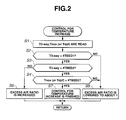
- Fig. 2 there is shown a flowchart that depicts programmed operation steps for controlling the temperature increase of NOx trapping catalytic converter 14 and/or diesel particulate filter (DPF) 15 to the third predetermined degree (viz., about 600 °C).
- DPF diesel particulate filter
- step S1 the temperature "T3-way” of HC adsorption type three-way catalytic converter 13, that "Tnox” of NOx trapping catalytic converter 14 and/or that "Tdpf” of diesel particulate filter (DPF) 15 are read. More specifically, the temperature of a catalyst bed or filter bed of such device 13, 14 and/or 15 is detected and read. Then, at step S2, judgment is carried out as to whether or not the temperature "T3-way” of HC adsorption type three-way catalytic converter 13 is higher than a first predetermined temperature "#TBED1" that is the oxidization activation temperature of converter 13.
- a first predetermined temperature "#TBED1" that is the oxidization activation temperature of converter 13.
- step S3 If YES, that is, when the temperature "T3-way” of converter 13 is higher than the first predetermined temperature "#TBED1", the operation step goes to step S3. While, if NO, that is, when the temperature "T3-way” of converter 13 is lower than or equal to the first predetermined temperature "#TBED1", the operation step goes to step S5.
- the first predetermined temperature "#TBED1" is a temperature that allows three-way catalytic converter 13 to exhibit a HC purifying rate higher than a predetermined rate (for example 50%) when the excess air ratio " ⁇ " of the exhaust gas led into converter 13 is relatively high (viz., the excess air ratio ⁇ is the target value determined in accordance with the operation condition of engine 1), and allows three-way catalytic converter 13 to exhibit the HC purifying rate (0% in the illustrated example) lower than the predetermined rate (viz., 50%) when the excess air ratio " ⁇ " of the exhaust gas led into converter 13 is relatively low (viz., ⁇ is about 1).
- the first predetermined temperature "#TBED1” may be referred to as "an oxidization activation temperature" of HC adsorption type three-way catalytic converter 13.
- the exhaust gas purifying performance of three-way catalytic converter 13 mainly depends on both the temperature of the catalyst bed of converter 13 and the excess air ratio " ⁇ " of the exhaust gas led into converter 13, and the HC purifying function of the three-way purifying performance can be expected at a relatively low temperature by increasing the excess air ratio " ⁇ " of the exhaust gas.
- step S3 judgment is carried out as to whether or not the temperature "T3-way” of HC adsorption type three-way catalytic converter 13 is higher than a second predetermined temperature "#TBED2" that is higher than the first predetermined temperature “#TBED1” and assures converter 13 of the three-way purifying performance. If YES, that is, when the temperature "T3-way” of converter 13 is higher than the second predetermined temperature "#TBED2", the operation step goes to step S4. While, if NO, that is, when the temperature "T3-way” of converter 13 is lower than or equal to the second predetermined temperature "#TBED2", the operation step goes to step S6.
- the second predetermined temperature "#TBED2" is a temperature that allows all the three components of three-way catalytic converter 13 to exhibit respective purifying rates higher than predetermined rates when the excess air ratio " ⁇ " of the exhaust gas led into converter 13 is relatively low. Accordingly, the second predetermined temperature "#TBED2” may be referred to as "a three-way catalyst activation temperature" of HC adsorption type three-way catalytic converter 13.
- step S4 judgment is carried out as to whether or not the temperature "Tnox” of NOx trapping catalytic converter 14 or the temperature “Tdpf” of diesel particulate filter (DPF) 15 is higher than a third predetermined temperature "#TBED3", for example 600 °C that assures converter 14 or filter 15 of the reactivation.
- a third predetermined temperature "#TBED3" for example 600 °C that assures converter 14 or filter 15 of the reactivation.
- step S4 If YES at step S4, that is, when the temperature "Tnox” or “Tdpf” is higher than the third predetermined temperature “#TBED3”, the operation flow goes to step S7. While, if NO at step S4, that is, when the temperature "Tnox” or “Tdpf” is lower than or equal to the third predetermined temperature "#TBED3", the operation flow goes to step S5.
- step S2 If NO at step S2, that is, when the temperature "T3-way” of HC adsorption type three-way catalytic converter 13 is lower than or equal to the first predetermined temperature "#TBED1" that is the oxidization activation temperature of converter 13, the operation flow goes to step S5.
- step S5 the excess air ratio " ⁇ " is lowered to about 1 by operating throttle valve 5 and/or EGR valve 12. That is, as is seen from the graph of Fig. 4, by reducing the open degree of throttle valve 5, or increasing the open degree of EGR valve 12 or effecting the both operation, the excess air ratio " ⁇ " is lowered to about 1.
- step S6 the excess air ratio " ⁇ " is increased by operating throttle valve 5 and/or EGR valve 12 in a reversed manner with respect to the operation manner at step S5. With this, the exhaust gas shows a leaner air/fuel ratio. At step S6, it is only necessary to increase the excess air ratio " ⁇ ".
- the excess air ratio " ⁇ " is controlled to the target excess air ratio that is set in the normal mode other than the exhaust gas temperature increasing mode and determined in accordance with an operation condition of engine 1. In fact, in such case, the exhaust gas shows its best quality with the target excess air ratio. If NO at step S4, that is, when the temperature "Tnox” of NOx trapping catalytic converter 14 or the temperature “Tdpf” of diesel particulate filter (DPF) 15 is lower than or equal to the third predetermined temperature "#TBED3", the operation flow goes to step S5 that has been described hereinabove. That is, at step S5, the excess air ratio " ⁇ " is lowered to about 1.
- step S4 While, if YES at step S4, that is, when the temperature "Tnox” of NOx trapping catalytic converter 14 or the temperature “Tdpf” of diesel particulate filter (DPF) 15 is higher than the third predetermined temperature "#TBED3", the operation flow goes to step S7 and the control for temperature increase is finished. Thereafter, NOx trapping catalyst converter 14 and/or diesel particulate filter (DPF) 15 is subjected to the control for reactivation. In case of reactivation of converter 14, the excess air ratio " ⁇ " is kept at about 1, while in case of reactivation of filter 15, the excess air ratio " ⁇ " is increased.
- the temperature of a diesel particulate filter is increased to the reactivation assuring temperature by operating a throttle valve.
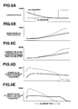
- two measures are used. One is to operate the throttle valve stepwise and the other is to operate the throttle valve continuously. With such first and second measures, in the temperature increase control, the excess air ratio is lowered stepwise and continuously, respectively.
- the excess air ratio is controlled stepwise.
- the excess air ratio is set relatively high (viz., a leaner air/fuel ratio) as compared with that set under warmed-up operation wherein the engine is sufficiently warmed or heated.
- the exhaust gas is forced to contain a larger amount of hydrocarbon (HC). That is, because of lowering of the excess air ratio, the engine is forced to produce a larger amount of HC. This undesired phenomenon will be well understood from Fig. 5D.
- the three-way catalytic converter fails to exhibit a satisfied oxidization function due to lack of oxygen in the exhaust gas.
- the three-way catalytic converter is forced to pass a larger amount of HC therethrough for a certain time, as is understood from Fig. 5E.
- the excess air ratio is totally high as compared with the rate that is provided in the above-mentioned first measure wherein the engine operation is kept with a lower excess air ratio.
- the amount of HC discharged by the engine can be reduced as compared with the first measure, as is seen from Fig. 6D.
- temperature increase of the exhaust gas is not speeded up, and thus, as compared with the case of the first measure, not only heating of the three-way catalytic converter but also heating of the diesel particulate filter or NOx trapping catalytic converter is delayed, as is seen from Figs. 6B and 6C.
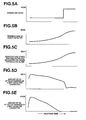
- the present invention is provided by paying attention to the temperature characteristic of the HC adsorption type three-way catalytic converter that is shown in the graph of Fig. 3.
- the three-way catalytic converter has different temperature characteristics between the HC purifying performance exhibited when the excess air ratio is high (viz., leaner air/fuel ratio) and the performance exhibited when the excess air ratio is low (viz., richer air/fuel ratio). That is, when the excess air ratio is high (viz., leaner air/fuel ratio), the practical oxidization activation of the three-way catalytic converter appears early.
- the excess air ratio is shifted from the lower side (viz., about 1) to a higher side (viz., leaner side).
- the exhaust gas led into three-way catalytic converter 13 is changed to show an oxygen richer property, and at the same time, the hydrocarbon adsorbed by the three-way catalyst of converter 13 under the cold operation is burnt (or oxidized) and thus purified. Due to burning (viz., oxidization) of the hydrocarbon which produces a certain heat, the temperature of the catalyst bed of converter 13 is increased sharply as is seen from Fig. 7B. As is seen from Fig.
- the exhaust gas discharged from HC adsorption type three-way catalytic converter 13 has a higher temperature and thus the catalyst bed of NOx trapping catalytic converter 14 and/or the filter bed of diesel particulate filter (DPF) 15, which is arranged downstream of the converter 13, is sufficiently heated. Furthermore, as is seen from Figs. 7A and 7D, when the excess air ratio is kept high (viz., leaner air/fuel ratio), the exhaust gas emitted from engine 1 shows a less amount of hydrocarbon.
- the catalyst bed of converter 13 shows the three-way catalyst activation temperature "#TBED2"
- the excess air ratio is shifted from the higher side to the lower side (about 1) again, as is seen from Figs. 7A and 7B.
- the exhaust gas from engine 1 shows the highest temperature and thus the temperature of the catalyst of converter 13 is instantly increased.
- the exhaust gas viz., HC
- the exhaust gas can be sufficiently purified by the three-way catalyst even though the excess air ratio is lowered to about 1, as is seen from Fig. 7E.
- the excess air ratio is raised once for the purpose of inducing an oxidization of hydrocarbon adsorbed by the catalyst.
- raising of the temperature of the catalyst of converter 13 is instantly carried out as compared with the above-mentioned first and second measures.
- the exhaust emission from engine 1 is improved as is seen from Fig. 7D.
Applications Claiming Priority (2)
| Application Number | Priority Date | Filing Date | Title |
|---|---|---|---|
| JP2002092459 | 2002-03-28 | ||
| JP2002092459A JP3855818B2 (ja) | 2002-03-28 | 2002-03-28 | ディーゼルエンジンの排気浄化装置 |
Publications (3)
| Publication Number | Publication Date |
|---|---|
| EP1350932A2 true EP1350932A2 (en) | 2003-10-08 |
| EP1350932A3 EP1350932A3 (en) | 2003-12-03 |
| EP1350932B1 EP1350932B1 (en) | 2005-01-19 |
Family
ID=28035859
Family Applications (1)
| Application Number | Title | Priority Date | Filing Date |
|---|---|---|---|
| EP03007047A Expired - Fee Related EP1350932B1 (en) | 2002-03-28 | 2003-03-27 | Exhaust emission control system of a diesel engine and method therefore |
Country Status (4)
| Country | Link |
|---|---|
| US (1) | US6742329B2 (es) |
| EP (1) | EP1350932B1 (es) |
| JP (1) | JP3855818B2 (es) |
| DE (1) | DE60300270T2 (es) |
Cited By (8)
| Publication number | Priority date | Publication date | Assignee | Title |
|---|---|---|---|---|
| EP1617060A1 (fr) * | 2004-07-15 | 2006-01-18 | Peugeot Citroen Automobiles SA | SYSTEME DE DESULFATATION D'UN PIEGE A NOx DISPOSE DANS UNE LIGNE D'ECHAPPEMENT D'UN MOTEUR DIESEL DE VEHICULE AUTOMOBILE |
| GB2416717A (en) * | 2004-07-29 | 2006-02-08 | Ford Global Tech Llc | A method for regenerating an exhaust treatment device |
| WO2007068328A1 (de) * | 2005-12-13 | 2007-06-21 | Volkswagen Aktiengesellschaft | Verfahren zur reduzierung der nox-emission von dieselmotoren |
| EP1837495A1 (de) * | 2006-03-23 | 2007-09-26 | Ford Global Technologies, LLC | Brennkraftmaschine mit Abgasnachbehandlung und Verfahren zum Betreiben einer derartigen Brennkraftmaschine |
| EP1837500A1 (de) * | 2006-03-23 | 2007-09-26 | Ford Global Technologies, LLC | Verfahren zur Steuerung einer Abgasnachbehandlung und zur Vorherbestimmung einer zukünftigen Temperatur in einem Partikelfilter einer Brennkraftmaschine |
| EP1837496A1 (de) * | 2006-03-23 | 2007-09-26 | Ford Global Technologies, LLC | Brennkraftmaschine mit kombiniertem Abgasnachbehandlungssystem und Verfahren zum Betreiben einer derartigen Brennkraftmaschine |
| EP2009265A1 (en) | 2007-06-05 | 2008-12-31 | Delphi Technologies, Inc. | Internal combustion engine system |
| FR3001256A1 (fr) * | 2013-01-21 | 2014-07-25 | Peugeot Citroen Automobiles Sa | Ligne d'echappement avec element a double fonction de depollution |
Families Citing this family (20)
| Publication number | Priority date | Publication date | Assignee | Title |
|---|---|---|---|---|
| US20050031513A1 (en) * | 2001-08-01 | 2005-02-10 | Mcnamara John Martin | Gasoline engine with an exhaust system for combusting particulate matter |
| JPWO2005052347A1 (ja) * | 2003-11-28 | 2007-06-21 | 株式会社日立製作所 | ディーゼルエンジンのegr制御装置およびモータ駆動式スロットル弁装置 |
| US7673445B2 (en) * | 2004-11-09 | 2010-03-09 | Ford Global Technologies, Llc | Mechanical apparatus having a catalytic NOx storage and conversion device |
| US7225613B2 (en) | 2005-01-26 | 2007-06-05 | Ford Global Technologies, Llc | Diesel engine after treatment device for conversion of nitrogen oxide and particulate matter |
| JP2007138924A (ja) * | 2005-10-17 | 2007-06-07 | Denso Corp | 内燃機関の排気浄化装置 |
| US7886524B2 (en) * | 2005-10-24 | 2011-02-15 | Ford Global Technologies, Llc | Method for controlling an internal combustion engine during regeneration of an emission after-treatment device |
| JP4349361B2 (ja) * | 2005-12-02 | 2009-10-21 | トヨタ自動車株式会社 | 内燃機関の排気浄化装置 |
| JP4458070B2 (ja) * | 2006-06-22 | 2010-04-28 | トヨタ自動車株式会社 | 内燃機関の排気浄化装置 |
| JP4647579B2 (ja) * | 2006-11-24 | 2011-03-09 | 本田技研工業株式会社 | 排ガス浄化システム |
| US9440192B2 (en) * | 2009-01-16 | 2016-09-13 | Basf Corporation | Diesel oxidation catalyst and use thereof in diesel and advanced combustion diesel engine systems |
| US8745971B2 (en) | 2010-03-11 | 2014-06-10 | Cummins Inc. | System, method, and apparatus for controlling an aftertreatment system having a particulate filter and a rich NOx conversion device |
| US9017616B2 (en) * | 2010-12-21 | 2015-04-28 | Toyota Jidosha Kabushiki Kaisha | Catalytic converter |
| DE102011009619A1 (de) * | 2011-01-28 | 2012-08-02 | Emitec Gesellschaft Für Emissionstechnologie Mbh | Verfahren zum Betrieb einer Abgasanlage |
| US8839605B2 (en) * | 2011-03-30 | 2014-09-23 | GM Global Technology Operations LLC | Exhaust methane control systems and methods |
| US8769932B2 (en) * | 2011-10-13 | 2014-07-08 | GM Global Technology Operations LLC | Cold start NO2 generation system |
| CN104405482B (zh) * | 2014-10-14 | 2017-04-26 | 安徽江淮汽车集团股份有限公司 | 排气处理系统 |
| JP6248974B2 (ja) * | 2014-10-24 | 2017-12-20 | トヨタ自動車株式会社 | 内燃機関の制御装置 |
| CN106368782A (zh) * | 2016-09-16 | 2017-02-01 | 北京工业大学 | 一种串联式冷起动hc排放主动吸附脱附装置及控制策略 |
| CN107269370A (zh) * | 2017-08-20 | 2017-10-20 | 芜湖乐普汽车科技有限公司 | 一种汽车排气管 |
| CN114352381A (zh) * | 2021-12-31 | 2022-04-15 | 潍柴动力扬州柴油机有限责任公司 | 一种控制降低dpf再生时温度的装置 |
Citations (3)
| Publication number | Priority date | Publication date | Assignee | Title |
|---|---|---|---|---|
| WO1998040611A1 (en) * | 1996-02-22 | 1998-09-17 | Volvo Personvagnar Ab | Device and method for reducing emissions in catalytic converter exhaust systems |
| WO2000053903A1 (en) * | 1999-03-11 | 2000-09-14 | Johnson Matthey Public Limited Company | Improvements in catalyst systems |
| EP1158143A2 (en) * | 1995-05-18 | 2001-11-28 | Toyota Jidosha Kabushiki Kaisha | Device for purifying the exhaust gas of a diesel engine |
Family Cites Families (11)
| Publication number | Priority date | Publication date | Assignee | Title |
|---|---|---|---|---|
| JP3246151B2 (ja) | 1993-12-25 | 2002-01-15 | 株式会社デンソー | ディーゼルエンジンの排気浄化装置 |
| JP2983429B2 (ja) * | 1994-02-25 | 1999-11-29 | 本田技研工業株式会社 | 内燃機関の排気ガス浄化装置 |
| JP3899534B2 (ja) * | 1995-08-14 | 2007-03-28 | トヨタ自動車株式会社 | ディーゼル機関の排気浄化方法 |
| JP3645704B2 (ja) * | 1997-03-04 | 2005-05-11 | トヨタ自動車株式会社 | 内燃機関の排気浄化装置 |
| JP3228232B2 (ja) * | 1998-07-28 | 2001-11-12 | トヨタ自動車株式会社 | 内燃機関の排気浄化装置 |
| US6167696B1 (en) * | 1999-06-04 | 2001-01-02 | Ford Motor Company | Exhaust gas purification system for low emission vehicle |
| US6293096B1 (en) * | 1999-06-23 | 2001-09-25 | Southwest Research Institute | Multiple stage aftertreatment system |
| US6304815B1 (en) * | 2000-03-29 | 2001-10-16 | Ford Global Technologies, Inc. | Method for controlling an exhaust gas temperature of an engine for improved performance of exhaust aftertreatment systems |
| JP3733834B2 (ja) * | 2000-05-02 | 2006-01-11 | 日産自動車株式会社 | 内燃機関の排気浄化装置 |
| DE60107765T2 (de) * | 2000-06-29 | 2005-05-12 | Toyota Jidosha K.K., Toyota | Vorrichtung zur Reinigung des Abgases einer Brennkraftmaschine |
| JP2002188432A (ja) * | 2000-12-19 | 2002-07-05 | Isuzu Motors Ltd | ディーゼルエンジンの排気浄化装置 |
-
2002
- 2002-03-28 JP JP2002092459A patent/JP3855818B2/ja not_active Expired - Fee Related
-
2003
- 2003-02-28 US US10/375,259 patent/US6742329B2/en not_active Expired - Lifetime
- 2003-03-27 EP EP03007047A patent/EP1350932B1/en not_active Expired - Fee Related
- 2003-03-27 DE DE60300270T patent/DE60300270T2/de not_active Expired - Lifetime
Patent Citations (3)
| Publication number | Priority date | Publication date | Assignee | Title |
|---|---|---|---|---|
| EP1158143A2 (en) * | 1995-05-18 | 2001-11-28 | Toyota Jidosha Kabushiki Kaisha | Device for purifying the exhaust gas of a diesel engine |
| WO1998040611A1 (en) * | 1996-02-22 | 1998-09-17 | Volvo Personvagnar Ab | Device and method for reducing emissions in catalytic converter exhaust systems |
| WO2000053903A1 (en) * | 1999-03-11 | 2000-09-14 | Johnson Matthey Public Limited Company | Improvements in catalyst systems |
Non-Patent Citations (1)
| Title |
|---|
| PATENT ABSTRACTS OF JAPAN vol. 1995, no. 10, 30 November 1995 (1995-11-30) & JP 07 189654 A (NIPPONDENSO CO LTD), 28 July 1995 (1995-07-28) * |
Cited By (13)
| Publication number | Priority date | Publication date | Assignee | Title |
|---|---|---|---|---|
| US7225608B2 (en) | 2004-07-15 | 2007-06-05 | Peugeot Citroen Automobiles Sa | System for purging sulfate from a NOx trap located in an exhaust line of a motor vehicle diesel engine |
| FR2873159A1 (fr) * | 2004-07-15 | 2006-01-20 | Peugeot Citroen Automobiles Sa | Systeme de desulfatation d'un piege a nox dispose dans une ligne d'echappement d'un moteur diesel de vehicule automobile |
| EP1617060A1 (fr) * | 2004-07-15 | 2006-01-18 | Peugeot Citroen Automobiles SA | SYSTEME DE DESULFATATION D'UN PIEGE A NOx DISPOSE DANS UNE LIGNE D'ECHAPPEMENT D'UN MOTEUR DIESEL DE VEHICULE AUTOMOBILE |
| GB2416717B (en) * | 2004-07-29 | 2009-02-11 | Ford Global Tech Llc | A method for regenerating an exhaust treatment device |
| GB2416717A (en) * | 2004-07-29 | 2006-02-08 | Ford Global Tech Llc | A method for regenerating an exhaust treatment device |
| WO2007068328A1 (de) * | 2005-12-13 | 2007-06-21 | Volkswagen Aktiengesellschaft | Verfahren zur reduzierung der nox-emission von dieselmotoren |
| EP1837495A1 (de) * | 2006-03-23 | 2007-09-26 | Ford Global Technologies, LLC | Brennkraftmaschine mit Abgasnachbehandlung und Verfahren zum Betreiben einer derartigen Brennkraftmaschine |
| EP1837500A1 (de) * | 2006-03-23 | 2007-09-26 | Ford Global Technologies, LLC | Verfahren zur Steuerung einer Abgasnachbehandlung und zur Vorherbestimmung einer zukünftigen Temperatur in einem Partikelfilter einer Brennkraftmaschine |
| EP1837496A1 (de) * | 2006-03-23 | 2007-09-26 | Ford Global Technologies, LLC | Brennkraftmaschine mit kombiniertem Abgasnachbehandlungssystem und Verfahren zum Betreiben einer derartigen Brennkraftmaschine |
| EP2009265A1 (en) | 2007-06-05 | 2008-12-31 | Delphi Technologies, Inc. | Internal combustion engine system |
| US8381513B2 (en) | 2007-06-05 | 2013-02-26 | Delphi Technologies Holding S.Arl | Internal combustion engine system |
| EP2009265B1 (en) * | 2007-06-05 | 2018-10-03 | Delphi International Operations Luxembourg S.à r.l. | Compression-ignition internal combustion engine system |
| FR3001256A1 (fr) * | 2013-01-21 | 2014-07-25 | Peugeot Citroen Automobiles Sa | Ligne d'echappement avec element a double fonction de depollution |
Also Published As
| Publication number | Publication date |
|---|---|
| EP1350932B1 (en) | 2005-01-19 |
| JP3855818B2 (ja) | 2006-12-13 |
| US20030182932A1 (en) | 2003-10-02 |
| DE60300270T2 (de) | 2005-06-23 |
| DE60300270D1 (de) | 2005-02-24 |
| EP1350932A3 (en) | 2003-12-03 |
| JP2003286877A (ja) | 2003-10-10 |
| US6742329B2 (en) | 2004-06-01 |
Similar Documents
| Publication | Publication Date | Title |
|---|---|---|
| EP1350932B1 (en) | Exhaust emission control system of a diesel engine and method therefore | |
| US6742331B2 (en) | Device for purifying exhaust gas of diesel engines | |
| US7207171B2 (en) | Exhaust gas purifying method and exhaust gas purifying system | |
| EP1725759B1 (en) | Exhaust purifying apparatus and exhaust purifying method for internal combustion engine | |
| EP1555401B1 (en) | Exhaust purifying apparatus for internal combustion engine | |
| US7743606B2 (en) | Exhaust catalyst system | |
| US7115237B2 (en) | Exhaust gas purifying method and exhaust gas purifying system | |
| JP5257024B2 (ja) | 内燃機関の排気浄化装置 | |
| JP2003065116A (ja) | 内燃機関の排気浄化装置 | |
| JP2004340032A (ja) | 内燃機関の排気浄化装置 | |
| US7451593B2 (en) | Exhaust gas cleaning method and exhaust gas cleaning system | |
| US20030172644A1 (en) | Deisel engine exhaust purifying device | |
| US7963101B2 (en) | Exhaust gas purifying device for an internal combustion engine | |
| JP2005076508A (ja) | エンジンの排気還流装置 | |
| US10933374B2 (en) | Exhaust emission control device, method and computer program product for an engine | |
| JP4012037B2 (ja) | 排気浄化装置 | |
| JP3778016B2 (ja) | 内燃機関の排気浄化装置 | |
| JP2008128212A (ja) | 内燃機関の排気浄化装置 | |
| JP3888115B2 (ja) | 内燃機関の制御装置 | |
| KR100892538B1 (ko) | 디젤매연여과장치의 재생시 질소산화물 흡장성능 향상을위한 배기가스 후처리장치 | |
| JP4893493B2 (ja) | 内燃機関の排気浄化装置 | |
| JP2006274985A (ja) | 排気後処理装置 | |
| JP2006037857A (ja) | 排気浄化装置 | |
| JP4349096B2 (ja) | 内燃機関の排気浄化装置 | |
| JP2016173039A (ja) | 排出ガス浄化システム |
Legal Events
| Date | Code | Title | Description |
|---|---|---|---|
| PUAI | Public reference made under article 153(3) epc to a published international application that has entered the european phase |
Free format text: ORIGINAL CODE: 0009012 |
|
| 17P | Request for examination filed |
Effective date: 20030327 |
|
| AK | Designated contracting states |
Kind code of ref document: A2 Designated state(s): AT BE BG CH CY CZ DE DK EE ES FI FR GB GR HU IE IT LI LU MC NL PT RO SE SI SK TR |
|
| PUAL | Search report despatched |
Free format text: ORIGINAL CODE: 0009013 |
|
| AK | Designated contracting states |
Kind code of ref document: A3 Designated state(s): AT BE BG CH CY CZ DE DK EE ES FI FR GB GR HU IE IT LI LU MC NL PT RO SE SI SK TR |
|
| GRAP | Despatch of communication of intention to grant a patent |
Free format text: ORIGINAL CODE: EPIDOSNIGR1 |
|
| AKX | Designation fees paid |
Designated state(s): DE FR GB |
|
| GRAS | Grant fee paid |
Free format text: ORIGINAL CODE: EPIDOSNIGR3 |
|
| GRAA | (expected) grant |
Free format text: ORIGINAL CODE: 0009210 |
|
| AK | Designated contracting states |
Kind code of ref document: B1 Designated state(s): DE FR GB |
|
| REG | Reference to a national code |
Ref country code: GB Ref legal event code: FG4D |
|
| REG | Reference to a national code |
Ref country code: IE Ref legal event code: FG4D |
|
| REF | Corresponds to: |
Ref document number: 60300270 Country of ref document: DE Date of ref document: 20050224 Kind code of ref document: P |
|
| PLBE | No opposition filed within time limit |
Free format text: ORIGINAL CODE: 0009261 |
|
| STAA | Information on the status of an ep patent application or granted ep patent |
Free format text: STATUS: NO OPPOSITION FILED WITHIN TIME LIMIT |
|
| ET | Fr: translation filed | ||
| 26N | No opposition filed |
Effective date: 20051020 |
|
| REG | Reference to a national code |
Ref country code: FR Ref legal event code: PLFP Year of fee payment: 14 |
|
| REG | Reference to a national code |
Ref country code: FR Ref legal event code: PLFP Year of fee payment: 15 |
|
| REG | Reference to a national code |
Ref country code: FR Ref legal event code: PLFP Year of fee payment: 16 |
|
| PGFP | Annual fee paid to national office [announced via postgrant information from national office to epo] |
Ref country code: GB Payment date: 20200318 Year of fee payment: 18 Ref country code: DE Payment date: 20200317 Year of fee payment: 18 |
|
| PGFP | Annual fee paid to national office [announced via postgrant information from national office to epo] |
Ref country code: FR Payment date: 20200214 Year of fee payment: 18 |
|
| REG | Reference to a national code |
Ref country code: DE Ref legal event code: R119 Ref document number: 60300270 Country of ref document: DE |
|
| GBPC | Gb: european patent ceased through non-payment of renewal fee |
Effective date: 20210327 |
|
| PG25 | Lapsed in a contracting state [announced via postgrant information from national office to epo] |
Ref country code: DE Free format text: LAPSE BECAUSE OF NON-PAYMENT OF DUE FEES Effective date: 20211001 Ref country code: FR Free format text: LAPSE BECAUSE OF NON-PAYMENT OF DUE FEES Effective date: 20210331 Ref country code: GB Free format text: LAPSE BECAUSE OF NON-PAYMENT OF DUE FEES Effective date: 20210327 |