EP1351859B1 - Procede et installation de vidange de futs - Google Patents
Procede et installation de vidange de futs Download PDFInfo
- Publication number
- EP1351859B1 EP1351859B1 EP01271308A EP01271308A EP1351859B1 EP 1351859 B1 EP1351859 B1 EP 1351859B1 EP 01271308 A EP01271308 A EP 01271308A EP 01271308 A EP01271308 A EP 01271308A EP 1351859 B1 EP1351859 B1 EP 1351859B1
- Authority
- EP
- European Patent Office
- Prior art keywords
- cask
- glove box
- installation
- bell
- bag
- Prior art date
- Legal status (The legal status is an assumption and is not a legal conclusion. Google has not performed a legal analysis and makes no representation as to the accuracy of the status listed.)
- Expired - Lifetime
Links
Images


Classifications
-
- B—PERFORMING OPERATIONS; TRANSPORTING
- B65—CONVEYING; PACKING; STORING; HANDLING THIN OR FILAMENTARY MATERIAL
- B65B—MACHINES, APPARATUS OR DEVICES FOR, OR METHODS OF, PACKAGING ARTICLES OR MATERIALS; UNPACKING
- B65B69/00—Unpacking of articles or materials, not otherwise provided for
- B65B69/0075—Emptying systems for flexible intermediate bulk containers [FIBC]
- B65B69/0091—Emptying systems for flexible intermediate bulk containers [FIBC] using frames whereby the container is bottom supported
Definitions
- the present invention relates to an installation of emptying of barrels fitted with an internal double bag including an outer bag and an inner bag containing powdery products and a method of use of said installation.
- Containment is also a necessity for reasons both ecological and to protect health operators and in addition to prevent the product from coming into contact with the ambient atmosphere and is contaminated.
- the operators have so far been protected by clothing and gas masks or similar devices.
- this solution is not satisfactory because it makes handling difficult and unpleasant.
- this solution does not protect the products nor the environment, so you have to use systems more sophisticated.
- a glove box is an enclosure closed with openings leading to the interior gloves through which operators try to handle the products in a booth, for example example by taking a barrel, draining it into a other device for manufacturing a product or to have it transferred using a facility adequate to a specific location.
- This type of installation is extremely expensive and the handling of barrels quite difficult through glove installations which, of course, allow containment satisfactory.
- This type of installation called an isolator is not necessarily the best solution especially when the powder is to be loaded into a equipment such as a reactor, a dryer, etc. whose accessibility is reduced and it is difficult to place such an insulator above device or machine.
- the object of the present invention is to provide a installation combining the advantages of a gloves and a powder transfer system for carry out such operations while ensuring the product containment and also the protection of operator and the environment.
- the invention also relates to a method of use of this installation.
- the barrel emptying installation according to the invention is characterized by the characterizing clause of the claim 1.
- the advantage of the installation according to the invention is the on the one hand, it is easy to have a glove box, which has already proven itself, on a drum fitted with two internal bags, one of which is located outside of each other, use a cane of suction to suck up the product and thereafter, always handling through the glove box, put another keg in place of the first one and use this in a very flexible way.
- the lower part of the bell comprises a flat surface provided on its face bottom of a flat seal allowing, when positioning of the glove box on the barrel, sealing between the two, said surface plane being provided with an annular opening formed a retaining ring provided with means for retaining the upper part of the bags.
- Figures 1 is a schematic side view of the installation according to the invention.
- Figure 2 is an enlarged view of the bell placed on a barrel.
- Figures 3-13 are partial views of the installation illustrating the steps of the process.
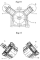
- Figure 14 is a plan view of the bell.
- Figure 15 is a sectional view of two filters.
- Figure 16 is a schematic view of the device cleaning.
- Figure 1 there is a barrel containing the product powder to drain.
- Bell 2 cane 3 and a support frame 5.
- the barrel 1 has inside two bags 11 and 12 basically made of plastic each independently closed, bag 11 will be called outer bag and bag 12 bag interior. These two bags ensure the confinement of the powdered product even after the opening of the barrel, that is to say after removing its lid.
- Glove box 2 is fixed on a support 51 of the chassis 5 which is movable in the direction vertical.
- the suction rod 3 is suspended by a flexible link 52 and a pulley 53 to the chassis 5 for allow the cane to be removed or put in place during the various stages of the process.
- Chassis 5 has a flat surface with rollers 54 facilitating the movement of the barrels and in particular their positioning under the glove box 2.
- the suction rod essentially comprises a hose 31 connected to a suction device allowing transfer the product from the keg to another tank or directly in the reactor or device in which the product should be used.
- the pipe 31 is surrounded a flexible cuff 32 closed on its part superior and coming to connect in a tight way on the upper part of the glove box 2, as we will see it later, also ensuring the watertightness of the installation.
- the glove box includes a bell-shaped part 21 made of a material transparent for example acrylic glass through which the operator can see and follow the operations drain.
- a steel bell stainless provided with a part made of a material transparent to allow you to see inside the bell when in use.
- Two openings 22 placed on the side surface of the bell allow putting on tightly fitted gloves in these openings which allow the manipulation of different elements inside the bell.
- the upper part of the bell is provided with a opening 26 through which the rod passes 3 and in particular the pipe 31 while the flexible sleeve 32 is tightly fixed on the upper part of the opening 26.
- the lower part of the glove box has a retaining ring in stainless steel 24 forming an annular opening on the lower part 23 of the bell which is planar.
- the flat surface 23 is provided with a flat seal through which it comes to rest on the upper part of the barrel. The radial width of this flat surface makes it possible to adapt the glove box on drums whose diameter can be different, the main thing being that the bell can rest on the upper edge of the barrel by the flat seal thus ensuring sealing.
- the ring 24 is provided with a or two retaining rings 25 which will be used for maintain, as will be explained below, the two bags 11, 12 located inside the barrel 1.
- the glove box is fitted with a fixing device 28 by which this glove box is linked to the device vertical movement 51 of the chassis 5.
- the upper edge of the outer bag 11 is fixed to the retaining ring 24 by means of the Oring 25 (fig 2). Then he opens the second bag 12 (fig. 7) and he throw the flexible link through the opening 29 and make keep the upper part also on the ring 24 with the same O ring or a second. AT from this moment the product can be vacuumed which is carried out by lowering the suction rod (fig. 8) and by guiding it inside the barrel to be able suck the product up to the smallest corner finding it inside. The operator, during this phase, manipulates the suction rod without being in contact with the product which is confined inside glove box installation - drum and without wearing special clothing or equipment.
- the product to be transferred contains solvent or it can react in contact with air or humidity can put the installation under a nitrogen atmosphere.
- bell 2 In order to ensure work inside installation with a slight depression, bell 2 (fig 14) has two openings on the surface side with two smooth tubes 7, 8. Each tube is provided with a filter 71, 72 mounted in leaktight manner.
- a ventilation circuit By means of a ventilation circuit, a air circulation (or nitrogen if necessary) between two filters to create a slight depression at inside the installation and avoid any leakage product in case of handling error or other problem.
- These filters 71, 72 are cartridges standard push-through filters, that is to say just push the new cartridge on the old one to put it in place, the old one falling in the glove box to be evacuated through opening 29.
- Figure 15 partially illustrates the passage of air (or nitrogen) through filters 71, 72.
- FIG. 16 is a diagrammatic representation of a system cleaning device, i.e. bell and cane.
- a system cleaning device i.e. bell and cane.
- the barrel 8 includes a drain opening 84.
- the bell on barrel 8 we seal the conduits with two filters and spray cleaning.
- the cleaning liquid is run between the sheath 32 and the tube 31. After cleaning, we empty the liquid to a suitable pit or container.
- the installation described is very flexible because it can be moved and used with different equipment. In addition, it is possible to install it on a weighing device allowing to control the amount of product aspirated.
- the glove box can be easily adapted to different diameters or even geometries of barrels in changing the face 23.
Description
Claims (9)
- Installation de vidange de fûts (1) équipés d'une double sache interne constituée d'une sache extérieure (11) et une sache intérieure (12) contenant des produits pulvérulents, caractérisée par le fait qu'elle comprend une boíte à gants constituée d'une cloche (2) faite au moins partiellement d'un matériau transparent muni sur sa partie supérieure d'une ouverture (26) pour le passage d'une canne d'aspiration (3) équipée de moyens assurant l'étanchéité entre ladite canne (3) et la cloche (2), que la partie inférieure de la cloche est munie de moyens (23, 24) pour venir se placer sur la partie supérieure d'un fût (1) de manière étanche et des moyens (25) permettant de maintenir les parties supérieures de deux saches après leur ouverture contre la partie inférieure de ladite cloche.
- Installation selon la revendication 1, caractérisée par le fait que la partie inférieure de ladite cloche comprend une surface plane munie d'un joint plat monté sur la face inférieure pour assurer l'étanchéité avec le fût à vider, ladite surface plane est pourvue d'une ouverture annulaire formée d'un anneau de maintien muni des moyens pour maintenir la partie supérieure des saches.
- Installation selon la revendication 1, caractérisée par le fait que la boíte à gants (2) et la canne d'aspiration (3) sont montées sur un châssis (5) agencé pour pouvoir monter et descendre l'ensemble boíte à gants et canne d'aspiration au-dessus d'un fût (1) à vidanger.
- Installation selon une des revendications 1 à 3, caractérisée par le fait que la boíte à gants est munie d'un dispositif de filtrage permettant de maintenir l'installation sous une dépression.
- Installation selon la revendication 4 caractérisée par le fait que le dispositif de filtration est constitué de deux ouvertures sur la surface latérale de la cloche munies de deux tubes lisses (7, 8) dans lesquels un filtre (71, 72) est monté de manière étanche et les deux tubes sont connectés à un dispositif de circulation d'air.
- Installation selon l'une des revendications 1 à 5 caractérisée par le fait qu'elle comprend un dispositif de nettoyage de la cloche constitué d'un fût muni sur la partie supérieure d'une entrée (81) pour le liquide de nettoyage vers un tuyau flexible muni d'un pistolet (83).
- Installation selon l'une revendications 1 à 4, caractérisée par le fait que la boíte à gants est munie d'une ouverture (29) pour l'évacuation des déchets des saches lors du changement du fût.
- Procédé d'utilisation de l'installation selon l'une des revendications 1 à 7 caractérisé par les étapes suivantes : on ouvre le fût à vidanger en retirant son couvercle et on le place sous la boíte à gants, on introduit une bague d'étanchéité jetable dans la partie supérieure de la sache extérieure et on l'introduit dans l'anneau de la cloche, on ouvre la sache extérieure, on descend la boite à gants sur le fût jusqu'à ce qu'elle soit en contact étanche avec le fût, on fixe à travers les gants la sache extérieure sur l'anneau de maintien au moyen de l'anneau d'étanchéité, on ouvre la sache intérieure et on la fixe aussi sur l'anneau de maintien, on retire les mains des gants et on procède à la vidange du fût au moyen de la canne d'aspiration, lorsque le fût est vide, on détache au moyen des gants la sache intérieure et on la laisse tomber à l'intérieur du fût avec la bague d'étanchéité, on soulève la boíte à gants sur une hauteur déterminée en maintenant la sache extérieure sur l'anneau de maintien et au moyen de deux attaches on ferme la sache sur deux endroits éloignés axiallement, on coupe la sache entre ces deux endroits, on laisse tomber la partie inférieure de la sache à l'intérieur du fût la partie supérieure restant sur la boíte à gants, on éloigne le fût vide, on approche un nouveau fût et on recommence la même méthode sauf que, avant la fixation de la sache extérieure sur l'anneau de maintien, on évacue la partie restante de la sache précédente à travers l'ouverture de la boite à gants.
- Procédé selon la revendication 8 caractérisé par le fait que le transfert s'effectue sous une atmosphère d'azote.
Priority Applications (1)
| Application Number | Priority Date | Filing Date | Title |
|---|---|---|---|
| DE60105450.4T DE60105450T4 (de) | 2000-12-19 | 2001-12-18 | Verfahren und anlage zur leerung von fässern |
Applications Claiming Priority (3)
| Application Number | Priority Date | Filing Date | Title |
|---|---|---|---|
| FR0016595 | 2000-12-19 | ||
| FR0016595A FR2818261B1 (fr) | 2000-12-19 | 2000-12-19 | Installation de vidange de futs et procede d'utilisation de ladite installation |
| PCT/IB2001/002523 WO2002049920A1 (fr) | 2000-12-19 | 2001-12-18 | Procede et installation de vidange de futs |
Publications (2)
| Publication Number | Publication Date |
|---|---|
| EP1351859A1 EP1351859A1 (fr) | 2003-10-15 |
| EP1351859B1 true EP1351859B1 (fr) | 2004-09-08 |
Family
ID=8857878
Family Applications (1)
| Application Number | Title | Priority Date | Filing Date |
|---|---|---|---|
| EP01271308A Expired - Lifetime EP1351859B1 (fr) | 2000-12-19 | 2001-12-18 | Procede et installation de vidange de futs |
Country Status (10)
| Country | Link |
|---|---|
| US (1) | US6843283B2 (fr) |
| EP (1) | EP1351859B1 (fr) |
| JP (1) | JP4080875B2 (fr) |
| CN (1) | CN1201974C (fr) |
| AT (1) | ATE275503T1 (fr) |
| AU (1) | AU2002222369A1 (fr) |
| DE (2) | DE60105450T4 (fr) |
| ES (1) | ES2228747T3 (fr) |
| FR (1) | FR2818261B1 (fr) |
| WO (1) | WO2002049920A1 (fr) |
Families Citing this family (20)
| Publication number | Priority date | Publication date | Assignee | Title |
|---|---|---|---|---|
| CA2644688C (fr) * | 1999-04-20 | 2012-11-13 | Kankyo Engineering Co., Ltd. | Methode pour determiner une concentration d'acide nucleique cible, sondes pour acide nucleique concues pour cette methode et methode pour analyser les donnees ainsi obtenues |
| US6979166B2 (en) * | 2003-05-15 | 2005-12-27 | Kellogg Company | Vacuum wand assembly for extracting a product from a container |
| US8241127B2 (en) * | 2004-08-27 | 2012-08-14 | Igt | Wireless operation of a game device |
| US7381127B2 (en) * | 2005-08-12 | 2008-06-03 | Flow Sciences, Inc. | Apparatus for transferring hazardous material |
| MX2010013138A (es) | 2008-06-05 | 2010-12-20 | Kellog Co | Base transportadora unitaria y conformador y formador de estructura deslizante para formar un contenedor transportable. |
| US8104520B2 (en) | 2008-06-11 | 2012-01-31 | Kellogg Company | Gentle handling hopper and scrunched bag for filling and forming a transportable container |
| EP2662290A1 (fr) * | 2008-09-03 | 2013-11-13 | Kellogg Company | Conteneur transportable pour biens en vrac et procédé de formation de celui-ci |
| NL1037227C2 (nl) * | 2009-08-26 | 2011-03-01 | E C P Holland B V | Inrichting geschikt voor het aansluiten van een eerste opslageenheid op een tweede opslageenheid alsmede een dergelijke werkwijze. |
| CN101804869A (zh) * | 2010-02-26 | 2010-08-18 | 四川沱牌药业有限责任公司 | 双层无菌真空技术在大容量注射剂外包装中的应用 |
| CA3025532C (fr) | 2010-12-01 | 2020-06-02 | Kellogg Company | Dispositif de transport intermediaire pour former un contenant transportable pour des produits en vrac |
| JP5755466B2 (ja) * | 2011-03-01 | 2015-07-29 | 東洋ハイテック株式会社 | 粉粒体の吸引取出装置および粉粒体の吸引取出方法 |
| ES2400553B1 (es) * | 2011-04-01 | 2014-03-18 | Seppelec, S.L. | Maquinaria para el vaciado de bidones de forma automática e higiénica |
| US9039523B2 (en) | 2012-06-22 | 2015-05-26 | Igt | Avatar as security measure for mobile device use with electronic gaming machine |
| CN104470812B (zh) * | 2012-07-13 | 2016-04-13 | 莫雷托股份公司 | 颗粒状物料存储器的清空装置 |
| DE102014200452A1 (de) * | 2014-01-13 | 2015-07-16 | Hecht Technologie Gmbh | Entleerungseinrichtung |
| EP2937145B1 (fr) * | 2014-04-24 | 2017-06-07 | Robatech AG | Dispositif de transport d'un fluide à fines particules |
| CN104261319A (zh) * | 2014-09-16 | 2015-01-07 | 昆山恒诚荣机械设备有限公司 | 吨包清料装置 |
| US9927244B2 (en) | 2016-07-20 | 2018-03-27 | Igt | Gaming system and method for locating an electronic gaming machine with a mobile device |
| US10916090B2 (en) | 2016-08-23 | 2021-02-09 | Igt | System and method for transferring funds from a financial institution device to a cashless wagering account accessible via a mobile device |
| US11707771B2 (en) | 2019-04-05 | 2023-07-25 | Baxter Healthcare Sa | Cleaning process for a powder transfer system |
Citations (1)
| Publication number | Priority date | Publication date | Assignee | Title |
|---|---|---|---|---|
| US5791123A (en) * | 1993-03-23 | 1998-08-11 | Helpmann Verfahrenstechnik Gmbh | Method and apparatus for decanting hazardous substances into containers |
Family Cites Families (7)
| Publication number | Priority date | Publication date | Assignee | Title |
|---|---|---|---|---|
| US3061165A (en) * | 1960-09-01 | 1962-10-30 | Racine Ind Plant Inc | Lined container package |
| US4182386A (en) * | 1977-11-30 | 1980-01-08 | Semi-Bulk Systems, Inc. | Closed system and container for dust free loading and unloading of powdered materials |
| WO1982004242A1 (fr) * | 1981-06-04 | 1982-12-09 | Eller John | Amelioration a l'emballage et a la distribution de liquides |
| US4991633A (en) * | 1990-01-31 | 1991-02-12 | Mallinckrodt, Inc. | Sanitary packaging system |
| DE19526743A1 (de) * | 1995-07-21 | 1997-01-23 | Wacker Chemie Gmbh | Verfahren zum Befüllen und Entleeren eines Behälters |
| CA2189075C (fr) * | 1995-10-02 | 2001-12-18 | Klaus Wilhelm | Appareil de dechargement de materiaux en vrac |
| DE19628429C2 (de) * | 1996-07-15 | 1999-03-11 | Klaus Wilhelm | Entleervorrichtung für rieselfähiges Schüttgut |
-
2000
- 2000-12-19 FR FR0016595A patent/FR2818261B1/fr not_active Expired - Fee Related
-
2001
- 2001-12-18 WO PCT/IB2001/002523 patent/WO2002049920A1/fr active IP Right Grant
- 2001-12-18 CN CNB018208959A patent/CN1201974C/zh not_active Expired - Lifetime
- 2001-12-18 AT AT01271308T patent/ATE275503T1/de not_active IP Right Cessation
- 2001-12-18 ES ES01271308T patent/ES2228747T3/es not_active Expired - Lifetime
- 2001-12-18 EP EP01271308A patent/EP1351859B1/fr not_active Expired - Lifetime
- 2001-12-18 AU AU2002222369A patent/AU2002222369A1/en not_active Abandoned
- 2001-12-18 DE DE60105450.4T patent/DE60105450T4/de not_active Expired - Lifetime
- 2001-12-18 JP JP2002551434A patent/JP4080875B2/ja not_active Expired - Lifetime
- 2001-12-18 DE DE60105450A patent/DE60105450D1/de not_active Expired - Lifetime
- 2001-12-18 US US10/451,087 patent/US6843283B2/en not_active Expired - Lifetime
Patent Citations (1)
| Publication number | Priority date | Publication date | Assignee | Title |
|---|---|---|---|---|
| US5791123A (en) * | 1993-03-23 | 1998-08-11 | Helpmann Verfahrenstechnik Gmbh | Method and apparatus for decanting hazardous substances into containers |
Also Published As
| Publication number | Publication date |
|---|---|
| DE60105450D1 (de) | 2004-10-14 |
| EP1351859A1 (fr) | 2003-10-15 |
| DE60105450T4 (de) | 2017-12-14 |
| CN1481318A (zh) | 2004-03-10 |
| JP2004516198A (ja) | 2004-06-03 |
| ATE275503T1 (de) | 2004-09-15 |
| DE60105450T2 (de) | 2005-10-13 |
| FR2818261B1 (fr) | 2003-02-21 |
| US20040040617A1 (en) | 2004-03-04 |
| FR2818261A1 (fr) | 2002-06-21 |
| ES2228747T3 (es) | 2005-04-16 |
| JP4080875B2 (ja) | 2008-04-23 |
| US6843283B2 (en) | 2005-01-18 |
| CN1201974C (zh) | 2005-05-18 |
| AU2002222369A1 (en) | 2002-07-01 |
| WO2002049920A1 (fr) | 2002-06-27 |
Similar Documents
| Publication | Publication Date | Title |
|---|---|---|
| EP1351859B1 (fr) | Procede et installation de vidange de futs | |
| FR2703340A1 (fr) | Installation et procédé de transfert de produits s'écoulant par gravité. | |
| US6056731A (en) | Suction device for body fluids | |
| US7909071B2 (en) | Method for the contamination-preventing emptying and filling of bulk containers | |
| JPS62503164A (ja) | 閉鎖可能なバツグ及びその無菌的な充填方法と装置 | |
| JP6961240B2 (ja) | 滅菌粒状バルク物質を搬送し、滅菌粒状バルク物質をアイソレーター内に移送する方法、並びに、コンテナ、アイソレーター及びアイソレーターとコンテナとの組合せ | |
| EP0004241B1 (fr) | Dispositif de jonction entre un conteneur et une enceinte de déchargement | |
| FR2722607A1 (fr) | Systeme pour faciliter le transfert sur d'une substance dangereuse | |
| RU2381155C2 (ru) | Устройство для заполнения жидкостью аэрозольного сосуда, установка для заполнения, содержащая такое устройство, колпачок и аэрозольный сосуд, содержащий такое устройство для заполнения | |
| JPH05270521A (ja) | 有害媒体の充填装置 | |
| FR3074484A1 (fr) | Container inertable de transport d'une poudre de fabrication additive | |
| US5676185A (en) | Vented drum funnel | |
| FR2555092A1 (fr) | Procede et dispositif pour confiner la pollution d'une enceinte de pressage isostatique | |
| US20220338848A1 (en) | Releasing stopper, container provided with stopper and kits and releasing method associated thereto | |
| EP1116242A1 (fr) | Procede et installation de remplissage de futs contenant des dechets dangereux | |
| FR3033077A1 (fr) | Dispositif de transfert entre un conteneur et une cellule et procede de mise en oeuvre | |
| US3933186A (en) | Protective housing for a liquid sample container | |
| KR102343482B1 (ko) | 화학 약품 자동 용기 개폐 및 약액 이송 시스템 | |
| US20210253337A1 (en) | Device for Storing and Transporting Bulk Material, in Particular Pharmaceutical Bulk Material, as Well as a Method for Filling a Device of This Kind With Said Bulk Material and for Emptying a Device Filled with Said Bulk Material | |
| EP1702871A1 (fr) | Conteneur souple à élément de guidage incorporé | |
| EP0414601B1 (fr) | Machine de remplissage en poudre de gaines | |
| US5950642A (en) | Clean connection and sampling apparatus and method | |
| FR2832655A1 (fr) | Dispositif d'extraction de gaz a efficacite amelioree | |
| EP4090624B1 (fr) | Procédé et appareil pour réaliser une liaison aseptique entre une unité vanne et un contenant formant fût | |
| JPH07191447A (ja) | 写真処理装置 |
Legal Events
| Date | Code | Title | Description |
|---|---|---|---|
| PUAI | Public reference made under article 153(3) epc to a published international application that has entered the european phase |
Free format text: ORIGINAL CODE: 0009012 |
|
| 17P | Request for examination filed |
Effective date: 20030620 |
|
| AK | Designated contracting states |
Kind code of ref document: A1 Designated state(s): AT BE CH CY DE DK ES FI FR GB GR IE IT LI LU MC NL PT SE TR |
|
| AX | Request for extension of the european patent |
Extension state: AL LT LV MK RO SI |
|
| GRAP | Despatch of communication of intention to grant a patent |
Free format text: ORIGINAL CODE: EPIDOSNIGR1 |
|
| GRAS | Grant fee paid |
Free format text: ORIGINAL CODE: EPIDOSNIGR3 |
|
| GRAA | (expected) grant |
Free format text: ORIGINAL CODE: 0009210 |
|
| AK | Designated contracting states |
Kind code of ref document: B1 Designated state(s): AT BE CH CY DE DK ES FI FR GB GR IE IT LI LU MC NL PT SE TR |
|
| PG25 | Lapsed in a contracting state [announced via postgrant information from national office to epo] |
Ref country code: TR Free format text: LAPSE BECAUSE OF FAILURE TO SUBMIT A TRANSLATION OF THE DESCRIPTION OR TO PAY THE FEE WITHIN THE PRESCRIBED TIME-LIMIT Effective date: 20040908 Ref country code: FI Free format text: LAPSE BECAUSE OF FAILURE TO SUBMIT A TRANSLATION OF THE DESCRIPTION OR TO PAY THE FEE WITHIN THE PRESCRIBED TIME-LIMIT Effective date: 20040908 Ref country code: CY Free format text: LAPSE BECAUSE OF FAILURE TO SUBMIT A TRANSLATION OF THE DESCRIPTION OR TO PAY THE FEE WITHIN THE PRESCRIBED TIME-LIMIT Effective date: 20040908 Ref country code: NL Free format text: LAPSE BECAUSE OF FAILURE TO SUBMIT A TRANSLATION OF THE DESCRIPTION OR TO PAY THE FEE WITHIN THE PRESCRIBED TIME-LIMIT Effective date: 20040908 Ref country code: AT Free format text: LAPSE BECAUSE OF FAILURE TO SUBMIT A TRANSLATION OF THE DESCRIPTION OR TO PAY THE FEE WITHIN THE PRESCRIBED TIME-LIMIT Effective date: 20040908 |
|
| REG | Reference to a national code |
Ref country code: GB Ref legal event code: FG4D Free format text: NOT ENGLISH |
|
| REG | Reference to a national code |
Ref country code: CH Ref legal event code: EP |
|
| REG | Reference to a national code |
Ref country code: IE Ref legal event code: FG4D Free format text: FRENCH |
|
| REF | Corresponds to: |
Ref document number: 60105450 Country of ref document: DE Date of ref document: 20041014 Kind code of ref document: P |
|
| REG | Reference to a national code |
Ref country code: CH Ref legal event code: NV Representative=s name: BUGNION S.A. |
|
| REG | Reference to a national code |
Ref country code: SE Ref legal event code: TRGR |
|
| PG25 | Lapsed in a contracting state [announced via postgrant information from national office to epo] |
Ref country code: DK Free format text: LAPSE BECAUSE OF FAILURE TO SUBMIT A TRANSLATION OF THE DESCRIPTION OR TO PAY THE FEE WITHIN THE PRESCRIBED TIME-LIMIT Effective date: 20041208 Ref country code: GR Free format text: LAPSE BECAUSE OF FAILURE TO SUBMIT A TRANSLATION OF THE DESCRIPTION OR TO PAY THE FEE WITHIN THE PRESCRIBED TIME-LIMIT Effective date: 20041208 |
|
| PG25 | Lapsed in a contracting state [announced via postgrant information from national office to epo] |
Ref country code: LU Free format text: LAPSE BECAUSE OF NON-PAYMENT OF DUE FEES Effective date: 20041218 |
|
| GBT | Gb: translation of ep patent filed (gb section 77(6)(a)/1977) |
Effective date: 20041129 |
|
| PG25 | Lapsed in a contracting state [announced via postgrant information from national office to epo] |
Ref country code: MC Free format text: LAPSE BECAUSE OF NON-PAYMENT OF DUE FEES Effective date: 20041231 |
|
| LTIE | Lt: invalidation of european patent or patent extension |
Effective date: 20040908 |
|
| NLV1 | Nl: lapsed or annulled due to failure to fulfill the requirements of art. 29p and 29m of the patents act | ||
| REG | Reference to a national code |
Ref country code: ES Ref legal event code: FG2A Ref document number: 2228747 Country of ref document: ES Kind code of ref document: T3 |
|
| PLBE | No opposition filed within time limit |
Free format text: ORIGINAL CODE: 0009261 |
|
| STAA | Information on the status of an ep patent application or granted ep patent |
Free format text: STATUS: NO OPPOSITION FILED WITHIN TIME LIMIT |
|
| 26N | No opposition filed |
Effective date: 20050609 |
|
| PG25 | Lapsed in a contracting state [announced via postgrant information from national office to epo] |
Ref country code: PT Free format text: LAPSE BECAUSE OF NON-PAYMENT OF DUE FEES Effective date: 20050208 |
|
| REG | Reference to a national code |
Ref country code: FR Ref legal event code: PLFP Year of fee payment: 15 |
|
| REG | Reference to a national code |
Ref country code: FR Ref legal event code: PLFP Year of fee payment: 16 |
|
| REG | Reference to a national code |
Ref country code: FR Ref legal event code: PLFP Year of fee payment: 17 |
|
| REG | Reference to a national code |
Ref country code: CH Ref legal event code: PUE Owner name: FYDEC HOLDING SA, CH Free format text: FORMER OWNER: DIETRICH, YVES, CH |
|
| PGFP | Annual fee paid to national office [announced via postgrant information from national office to epo] |
Ref country code: SE Payment date: 20201215 Year of fee payment: 20 Ref country code: DE Payment date: 20201126 Year of fee payment: 20 Ref country code: IE Payment date: 20201127 Year of fee payment: 20 Ref country code: GB Payment date: 20201125 Year of fee payment: 20 Ref country code: FR Payment date: 20201125 Year of fee payment: 20 Ref country code: CH Payment date: 20201127 Year of fee payment: 20 Ref country code: IT Payment date: 20201210 Year of fee payment: 20 |
|
| PGFP | Annual fee paid to national office [announced via postgrant information from national office to epo] |
Ref country code: BE Payment date: 20201214 Year of fee payment: 20 |
|
| PGFP | Annual fee paid to national office [announced via postgrant information from national office to epo] |
Ref country code: ES Payment date: 20210107 Year of fee payment: 20 |
|
| REG | Reference to a national code |
Ref country code: DE Ref legal event code: R071 Ref document number: 60105450 Country of ref document: DE |
|
| REG | Reference to a national code |
Ref country code: CH Ref legal event code: PL |
|
| REG | Reference to a national code |
Ref country code: GB Ref legal event code: PE20 Expiry date: 20211217 |
|
| REG | Reference to a national code |
Ref country code: SE Ref legal event code: EUG |
|
| PG25 | Lapsed in a contracting state [announced via postgrant information from national office to epo] |
Ref country code: GB Free format text: LAPSE BECAUSE OF EXPIRATION OF PROTECTION Effective date: 20211217 |
|
| REG | Reference to a national code |
Ref country code: BE Ref legal event code: MK Effective date: 20211218 Ref country code: IE Ref legal event code: MK9A |
|
| REG | Reference to a national code |
Ref country code: ES Ref legal event code: FD2A Effective date: 20220405 |
|
| PG25 | Lapsed in a contracting state [announced via postgrant information from national office to epo] |
Ref country code: IE Free format text: LAPSE BECAUSE OF EXPIRATION OF PROTECTION Effective date: 20211218 |
|
| PG25 | Lapsed in a contracting state [announced via postgrant information from national office to epo] |
Ref country code: ES Free format text: LAPSE BECAUSE OF EXPIRATION OF PROTECTION Effective date: 20211219 |