EP1352207B1 - Laminated armor - Google Patents
Laminated armor Download PDFInfo
- Publication number
- EP1352207B1 EP1352207B1 EP01273165A EP01273165A EP1352207B1 EP 1352207 B1 EP1352207 B1 EP 1352207B1 EP 01273165 A EP01273165 A EP 01273165A EP 01273165 A EP01273165 A EP 01273165A EP 1352207 B1 EP1352207 B1 EP 1352207B1
- Authority
- EP
- European Patent Office
- Prior art keywords
- layer
- composite
- hardness
- rockwell
- panel
- Prior art date
- Legal status (The legal status is an assumption and is not a legal conclusion. Google has not performed a legal analysis and makes no representation as to the accuracy of the status listed.)
- Revoked
Links
Images
Classifications
-
- F—MECHANICAL ENGINEERING; LIGHTING; HEATING; WEAPONS; BLASTING
- F41—WEAPONS
- F41H—ARMOUR; ARMOURED TURRETS; ARMOURED OR ARMED VEHICLES; MEANS OF ATTACK OR DEFENCE, e.g. CAMOUFLAGE, IN GENERAL
- F41H5/00—Armour; Armour plates
- F41H5/02—Plate construction
- F41H5/04—Plate construction composed of more than one layer
- F41H5/0414—Layered armour containing ceramic material
- F41H5/0421—Ceramic layers in combination with metal layers
-
- F—MECHANICAL ENGINEERING; LIGHTING; HEATING; WEAPONS; BLASTING
- F41—WEAPONS
- F41H—ARMOUR; ARMOURED TURRETS; ARMOURED OR ARMED VEHICLES; MEANS OF ATTACK OR DEFENCE, e.g. CAMOUFLAGE, IN GENERAL
- F41H5/00—Armour; Armour plates
- F41H5/02—Plate construction
- F41H5/04—Plate construction composed of more than one layer
- F41H5/0442—Layered armour containing metal
- F41H5/0457—Metal layers in combination with additional layers made of fibres, fabrics or plastics
-
- Y—GENERAL TAGGING OF NEW TECHNOLOGICAL DEVELOPMENTS; GENERAL TAGGING OF CROSS-SECTIONAL TECHNOLOGIES SPANNING OVER SEVERAL SECTIONS OF THE IPC; TECHNICAL SUBJECTS COVERED BY FORMER USPC CROSS-REFERENCE ART COLLECTIONS [XRACs] AND DIGESTS
- Y10—TECHNICAL SUBJECTS COVERED BY FORMER USPC
- Y10S—TECHNICAL SUBJECTS COVERED BY FORMER USPC CROSS-REFERENCE ART COLLECTIONS [XRACs] AND DIGESTS
- Y10S428/00—Stock material or miscellaneous articles
- Y10S428/911—Penetration resistant layer
-
- Y—GENERAL TAGGING OF NEW TECHNOLOGICAL DEVELOPMENTS; GENERAL TAGGING OF CROSS-SECTIONAL TECHNOLOGIES SPANNING OVER SEVERAL SECTIONS OF THE IPC; TECHNICAL SUBJECTS COVERED BY FORMER USPC CROSS-REFERENCE ART COLLECTIONS [XRACs] AND DIGESTS
- Y10—TECHNICAL SUBJECTS COVERED BY FORMER USPC
- Y10T—TECHNICAL SUBJECTS COVERED BY FORMER US CLASSIFICATION
- Y10T428/00—Stock material or miscellaneous articles
- Y10T428/12—All metal or with adjacent metals
- Y10T428/12493—Composite; i.e., plural, adjacent, spatially distinct metal components [e.g., layers, joint, etc.]
- Y10T428/12535—Composite; i.e., plural, adjacent, spatially distinct metal components [e.g., layers, joint, etc.] with additional, spatially distinct nonmetal component
- Y10T428/12556—Organic component
- Y10T428/12569—Synthetic resin
-
- Y—GENERAL TAGGING OF NEW TECHNOLOGICAL DEVELOPMENTS; GENERAL TAGGING OF CROSS-SECTIONAL TECHNOLOGIES SPANNING OVER SEVERAL SECTIONS OF THE IPC; TECHNICAL SUBJECTS COVERED BY FORMER USPC CROSS-REFERENCE ART COLLECTIONS [XRACs] AND DIGESTS
- Y10—TECHNICAL SUBJECTS COVERED BY FORMER USPC
- Y10T—TECHNICAL SUBJECTS COVERED BY FORMER US CLASSIFICATION
- Y10T428/00—Stock material or miscellaneous articles
- Y10T428/12—All metal or with adjacent metals
- Y10T428/12493—Composite; i.e., plural, adjacent, spatially distinct metal components [e.g., layers, joint, etc.]
- Y10T428/12729—Group IIA metal-base component
-
- Y—GENERAL TAGGING OF NEW TECHNOLOGICAL DEVELOPMENTS; GENERAL TAGGING OF CROSS-SECTIONAL TECHNOLOGIES SPANNING OVER SEVERAL SECTIONS OF THE IPC; TECHNICAL SUBJECTS COVERED BY FORMER USPC CROSS-REFERENCE ART COLLECTIONS [XRACs] AND DIGESTS
- Y10—TECHNICAL SUBJECTS COVERED BY FORMER USPC
- Y10T—TECHNICAL SUBJECTS COVERED BY FORMER US CLASSIFICATION
- Y10T428/00—Stock material or miscellaneous articles
- Y10T428/12—All metal or with adjacent metals
- Y10T428/12493—Composite; i.e., plural, adjacent, spatially distinct metal components [e.g., layers, joint, etc.]
- Y10T428/12736—Al-base component
- Y10T428/12743—Next to refractory [Group IVB, VB, or VIB] metal-base component
-
- Y—GENERAL TAGGING OF NEW TECHNOLOGICAL DEVELOPMENTS; GENERAL TAGGING OF CROSS-SECTIONAL TECHNOLOGIES SPANNING OVER SEVERAL SECTIONS OF THE IPC; TECHNICAL SUBJECTS COVERED BY FORMER USPC CROSS-REFERENCE ART COLLECTIONS [XRACs] AND DIGESTS
- Y10—TECHNICAL SUBJECTS COVERED BY FORMER USPC
- Y10T—TECHNICAL SUBJECTS COVERED BY FORMER US CLASSIFICATION
- Y10T428/00—Stock material or miscellaneous articles
- Y10T428/12—All metal or with adjacent metals
- Y10T428/12493—Composite; i.e., plural, adjacent, spatially distinct metal components [e.g., layers, joint, etc.]
- Y10T428/12736—Al-base component
- Y10T428/1275—Next to Group VIII or IB metal-base component
- Y10T428/12757—Fe
-
- Y—GENERAL TAGGING OF NEW TECHNOLOGICAL DEVELOPMENTS; GENERAL TAGGING OF CROSS-SECTIONAL TECHNOLOGIES SPANNING OVER SEVERAL SECTIONS OF THE IPC; TECHNICAL SUBJECTS COVERED BY FORMER USPC CROSS-REFERENCE ART COLLECTIONS [XRACs] AND DIGESTS
- Y10—TECHNICAL SUBJECTS COVERED BY FORMER USPC
- Y10T—TECHNICAL SUBJECTS COVERED BY FORMER US CLASSIFICATION
- Y10T428/00—Stock material or miscellaneous articles
- Y10T428/12—All metal or with adjacent metals
- Y10T428/12493—Composite; i.e., plural, adjacent, spatially distinct metal components [e.g., layers, joint, etc.]
- Y10T428/12771—Transition metal-base component
- Y10T428/12778—Alternative base metals from diverse categories
-
- Y—GENERAL TAGGING OF NEW TECHNOLOGICAL DEVELOPMENTS; GENERAL TAGGING OF CROSS-SECTIONAL TECHNOLOGIES SPANNING OVER SEVERAL SECTIONS OF THE IPC; TECHNICAL SUBJECTS COVERED BY FORMER USPC CROSS-REFERENCE ART COLLECTIONS [XRACs] AND DIGESTS
- Y10—TECHNICAL SUBJECTS COVERED BY FORMER USPC
- Y10T—TECHNICAL SUBJECTS COVERED BY FORMER US CLASSIFICATION
- Y10T428/00—Stock material or miscellaneous articles
- Y10T428/12—All metal or with adjacent metals
- Y10T428/12493—Composite; i.e., plural, adjacent, spatially distinct metal components [e.g., layers, joint, etc.]
- Y10T428/12771—Transition metal-base component
- Y10T428/12806—Refractory [Group IVB, VB, or VIB] metal-base component
-
- Y—GENERAL TAGGING OF NEW TECHNOLOGICAL DEVELOPMENTS; GENERAL TAGGING OF CROSS-SECTIONAL TECHNOLOGIES SPANNING OVER SEVERAL SECTIONS OF THE IPC; TECHNICAL SUBJECTS COVERED BY FORMER USPC CROSS-REFERENCE ART COLLECTIONS [XRACs] AND DIGESTS
- Y10—TECHNICAL SUBJECTS COVERED BY FORMER USPC
- Y10T—TECHNICAL SUBJECTS COVERED BY FORMER US CLASSIFICATION
- Y10T428/00—Stock material or miscellaneous articles
- Y10T428/12—All metal or with adjacent metals
- Y10T428/12493—Composite; i.e., plural, adjacent, spatially distinct metal components [e.g., layers, joint, etc.]
- Y10T428/12771—Transition metal-base component
- Y10T428/12861—Group VIII or IB metal-base component
- Y10T428/12951—Fe-base component
- Y10T428/12958—Next to Fe-base component
- Y10T428/12965—Both containing 0.01-1.7% carbon [i.e., steel]
-
- Y—GENERAL TAGGING OF NEW TECHNOLOGICAL DEVELOPMENTS; GENERAL TAGGING OF CROSS-SECTIONAL TECHNOLOGIES SPANNING OVER SEVERAL SECTIONS OF THE IPC; TECHNICAL SUBJECTS COVERED BY FORMER USPC CROSS-REFERENCE ART COLLECTIONS [XRACs] AND DIGESTS
- Y10—TECHNICAL SUBJECTS COVERED BY FORMER USPC
- Y10T—TECHNICAL SUBJECTS COVERED BY FORMER US CLASSIFICATION
- Y10T428/00—Stock material or miscellaneous articles
- Y10T428/12—All metal or with adjacent metals
- Y10T428/12493—Composite; i.e., plural, adjacent, spatially distinct metal components [e.g., layers, joint, etc.]
- Y10T428/12771—Transition metal-base component
- Y10T428/12861—Group VIII or IB metal-base component
- Y10T428/12951—Fe-base component
- Y10T428/12972—Containing 0.01-1.7% carbon [i.e., steel]
-
- Y—GENERAL TAGGING OF NEW TECHNOLOGICAL DEVELOPMENTS; GENERAL TAGGING OF CROSS-SECTIONAL TECHNOLOGIES SPANNING OVER SEVERAL SECTIONS OF THE IPC; TECHNICAL SUBJECTS COVERED BY FORMER USPC CROSS-REFERENCE ART COLLECTIONS [XRACs] AND DIGESTS
- Y10—TECHNICAL SUBJECTS COVERED BY FORMER USPC
- Y10T—TECHNICAL SUBJECTS COVERED BY FORMER US CLASSIFICATION
- Y10T428/00—Stock material or miscellaneous articles
- Y10T428/12—All metal or with adjacent metals
- Y10T428/12493—Composite; i.e., plural, adjacent, spatially distinct metal components [e.g., layers, joint, etc.]
- Y10T428/12986—Adjacent functionally defined components
-
- Y—GENERAL TAGGING OF NEW TECHNOLOGICAL DEVELOPMENTS; GENERAL TAGGING OF CROSS-SECTIONAL TECHNOLOGIES SPANNING OVER SEVERAL SECTIONS OF THE IPC; TECHNICAL SUBJECTS COVERED BY FORMER USPC CROSS-REFERENCE ART COLLECTIONS [XRACs] AND DIGESTS
- Y10—TECHNICAL SUBJECTS COVERED BY FORMER USPC
- Y10T—TECHNICAL SUBJECTS COVERED BY FORMER US CLASSIFICATION
- Y10T428/00—Stock material or miscellaneous articles
- Y10T428/23—Sheet including cover or casing
- Y10T428/239—Complete cover or casing
-
- Y—GENERAL TAGGING OF NEW TECHNOLOGICAL DEVELOPMENTS; GENERAL TAGGING OF CROSS-SECTIONAL TECHNOLOGIES SPANNING OVER SEVERAL SECTIONS OF THE IPC; TECHNICAL SUBJECTS COVERED BY FORMER USPC CROSS-REFERENCE ART COLLECTIONS [XRACs] AND DIGESTS
- Y10—TECHNICAL SUBJECTS COVERED BY FORMER USPC
- Y10T—TECHNICAL SUBJECTS COVERED BY FORMER US CLASSIFICATION
- Y10T428/00—Stock material or miscellaneous articles
- Y10T428/31504—Composite [nonstructural laminate]
- Y10T428/31678—Of metal
Landscapes
- Engineering & Computer Science (AREA)
- Ceramic Engineering (AREA)
- General Engineering & Computer Science (AREA)
- Chemical & Material Sciences (AREA)
- Laminated Bodies (AREA)
- Aiming, Guidance, Guns With A Light Source, Armor, Camouflage, And Targets (AREA)
- Ceramic Capacitors (AREA)
- Materials For Medical Uses (AREA)
- Rigid Pipes And Flexible Pipes (AREA)
Abstract
Description
- The invention provides a composite, laminated armor panel for absorbing and dissipating kinetic energy from projectiles, and resists delamination in use. The panel comprises a lamination of at least three layers. A first outwardly positioned layer is made of a hard material such as a ceramic material or a metal having a Rockwell-C hardness of at least 27. An intermediate layer is softer than the first layer, being made of aluminium or other metals having a Rockwell-C hardness of less than 27. A third backing layer comprises tough woven textile material. All layers are laminated together and wrapped on at least four sides in a further tough woven textile material, which is bonded to the outer surfaces of the composite armor panel. The woven textile material wrapping the panel is preferably made of aramide synthetic fibers or polyethylene fibers.
- The present invention relates to armor for protection against projectiles.
- More particularly, the invention provides a lightweight multi-layer armor plate resistant to delamination.
- The aim of armor systems is to prevent the penetration of projectiles into a protected area by using protective panels of acceptable weight, volume and cost There are additional considerations such as durability, ease of fabrication and ease of repair if needed that will impinge on the selection of suitable armor:
- A further feature of a satisfactory armor system is that it is not degraded by a first projectile to such extent that a following projectile will penetrate the panel.
Generally, weight is the overriding consideration in aircraft, volume and weight are important in land vehicles, and cost is the main criteria in naval vessels and stationary applications. - The traditional method of armoring vehicles has long been the use of thick steel plates. Such armor is still used today in applications where weight is not of vital concem, for example in large naval vessels and in stationary applications.
- The main use of such armor in land vehicles has been in tanks. However contradictory requirements that the tank be fast and mobile, yet survive being hit by a shell from an opposing tank have posed a dilemma to tank designers. Much thought and experiment was devoted to the problem before and during the Second World War. The dilemma is well illustrated by a tank of German design, which was in use at the end of the war. The athe PzKpfw VI Ausf E Tiger tank was provided with steel armor varying in thickness between 26 and 110 mm. The tank weighed 57 ton, and a 694 hp engine was needed to drive this vehicle at its modest maximum speed of 37 km/h.
- With the development of the HEAT (High Explosive Anti-Tank) shell, armor designers were faced with a warhead having a shaped copper-lined hollow in the fonward edge of the explosive filling which detonated a short distance from the target armor. The explosive charge adopted a shape that created a jet of vaporized copper which burned through the armor. The warhead includes a mass of plastic explosive that is plastered by impact to the outer face of the steel armor and is then detonated.
- Threats of this type led to the development during the past 40 years of more complex armor systems, thinner versions of which were later adapted for use in the protection of medium-weight road vehicles from rifle and machine-gun fire. Multi-layer armor was developed and proved in many decades as having an improved penetration resistance/weight ratio relative to steel. Further innovations effected concern the use of ceramics, artificial fibers, and various arrangements designed to deflect the projectile sideways in an outer layer so that an inner layer of the armor could contain the projectile fragments. Such armor systems weigh significantly less than a solid steel panel providing equivalent protection.
- Reduced weight has enabled armor manufacturers to also meet the demand for protection of lighter road vehicles, mainly for military use, but increasingly also for civilian buses, vans and cars. Due to the large size of this market, much effort has been invested in developing armor that meets the difficult weight-volume-cost constraints for light vehicles. As has been explained in our previous Patent (6,112,635), armor for light vehicles is expected to prevent penetration of rifle bullets of any type, even when close-range fire is absorbed at velocities in the range 700 to 1000 meters per second. At present it is impracticable to protect light vehicles against high caliber armor-piercing projectiles; e.g. 12.7 and 14.5 mm, because the weight of suitable armor would impede the mobility and performance of such vehicles, and because room is not available for armor of the requisite thickness.
- With regard to military aircraft, armor has been provided for the area where the pilot and navigator sit. No method of armoring a complete aircraft is known.
- A large volume of patents has been issued for composite armor. The following are believed to be representative of the state of the art.
- King in British Patent No. 1,142,689 discloses an armor plate including a non-metallic matrix, which rigidly holds bodies of a hard shatter-resistant material. When such body is shattered by a projectile, the projectile is also fragmented, the fragments being absorbed by the matrix.
- A more complex arrangement is disclosed by Poole in US Patent no. 4,061,815. He proposes sandwiching at least one layer of polyurethane between rigid impact-resistant sheets, of material such as aluminium armor plate or fiberglass and a thin retaining sheet on the far side. An optional ceramic or metallic filler is embedded in the polyurethane. The lightweight armor is claimed to be suitable for aircraft. However as the lamination is between 5.08 -12.7 cm (2 - 5 inches) thick, it is difficult to imagine how such a high volume armor could be fitted into existing airplanes.
- In British patent No. 1,352,418 to the German company Feldmuhle Anlagen-und Produktions, the claimed innovation is high temperature bonding of adjacent layers. A first layer comprises at least 90% by weight of sintered alumina. At least one intermediate layer is metallic and has a greater coefficient of thermal expansion. The layers are bonded together at above 500°C.
- The present inventor has disclosed a composite armor panel in US Patent No. 6,112,635, which patent makes reference to a substantial number of prior-art patents for armor plate. An internal layer of Al2O3 pellets, preferably round, flat cylindrical or spherical, having an axis of at least 12 mm is bound in a solidified material. Most pellets are in direct contact with at least 6 other pellets. Outer layers of synthetic fibers or aluminium can be added. The panel resists several high-speed projectiles even if all rounds successively impact the same small area.
- A weakness of prior-art composite armor, which has not been accorded adequate consideration, concerns the problem of local delamination, which can occur as a result of impact, typically with a high-speed projectile. Following such delamination, the effected area loses much of its protective properties, resulting in a following round penetrating the armor plate in the delaminated area.
- It is therefore one of the objects of the present invention to obviate the disadvantages of prior art armor systems and to provide a composite armor panel that has improved resistance to delamination.
- The present invention achieves the above objects by providing a composite, laminated armor panel for absorbing and dissipating kinetic energy from projectiles, said panel comprising:
- a) a first outwardly-positioned layer made of a hard material seleded from a ceramic material and a metal having a Rockwell-C hardness of at least 27;
- b) an intermediate layer softer than said first layer, made of a material selected from aluminium and metals having a Rockwell-C hardness of less than 27; and
- c) a third backing layer of tough woven textile material
- In a preferred embodiment of the present invention there is provided a. composite, laminated armor panel wherein the first layer is formed of titanium, hard carbon steel or ceramics.
- In a most preferred embodiment of the present invention there is provided a composite, laminated armor panel wherein the intermediate layer is formed of low carbon steel, medium carbon steel or aluminium.
- Yet further embodiments of the invention will be described hereinafter.
- The believed cause of delamination of multi-layer armor panels when impacted by a projectile is the dissipation of kinetic energy by a projectile, which does not penetrate the panel. Such energy is dissipated in several ways, among them the application of shock vibration to an intermediate layer, which shock waves propagate laterally and horizontally to adjoining areas. In the present invention, the tightly wrapped outer layer absorbs a part of such energy and prevents loosening or separation of the armor panel layers.
- In US Patent 4,131,053 there is described and claimed composite, laminated armor panels having a specific number of lamination layers, wherein each lamination forms a continuous layer in the laminated armor panel and more specifically there is described and claimed an armor comprising first, second and third layers of different armor material secured together by a bonding material. This is the exact sort of armor that suffers from the problem of delamination which problem is solved by the present invention. More particularly, the present invention comprises three continuous layers plus a wrapped fourth layer on at least four sides of the laminated composite which wrapped fourth layer prevents the delamination of the laminated layers.
- In DE 1,584,284 there is described and claimed an armor material having an outer coating and inner particles however the outer coating described therein is described as a tubular container made preferably of steel or iron which is designed to contain particles made of such materials as titanium carbide, zirconium carbide, etc. and is totally unrelated to armor formed from multiple laminated layers and the problem of delamination suffered thereby.
- Thus said publications do not provide any teaching, suggestion, or motivation for wrapping the claimed three-layer composite laminated material of the present invention on at least four sides of the laminated composite with a further tough woven textile material and the advantages of preventing delamination achieved thereby.
- It will thus be realized that the novel armor of the present invention, by resisting delamination provides improved protection from the second, third and following rounds to impact the panel, and not merely from the first. Furthermore, additional and unexpected benefits are derived from wrapping the panel in an impregnated tough woven textile material such as Kevlar®.
- The wrapping prevents the ingress of toxic chemicals used in chemical warfare. Vehicle contamination is thus reduced and decontamination by conventional flushing equipment is readily performed.
- The hard materials used for the outer layer are naturally brittle, but are advantageous in effecting projectile velocity reduction and in particular in deforming the projectile, thereby easing the task of inner layers of the armor. The wrapping bonded to the hard outer steel plate reduces crack propagation in the hard material when hit by a projectile. This brings about a further improvement in the capacity of the composite armor plate of the present invention-to-resist multiple impacts in a small defined area of the panel.
- While during ballistic tests the bullets are fired directly at 90 degrees to the armor panel, armor used in the field will receive the vast majority of projectiles at some angle to the armor other than perpendicular. As the bullet punches through the hard outer skin, part of the bullet is already in contact with the softer intermediate layer Because the plane common to the outer and intermediate armor layer will rarely be precisely perpendicular to the bullet axis, the bullet will be fragmented or at least deflected from its course in a manner analogous to the refraction of light waves on a plane surface bounding two different transparent media. The third armor layer is then able to prevent penetration of the deflected bullet or its fragments.
- Ballistic tests were performed to validate the design. Test results obtained and listed herein fully validated expectations from the specified armor panel.
- The invention will now be described in connection with certain preferred embodiments with reference to the following illustrative figures so that it may be more fully understood.
- With specific reference now to the figures in detail, it is stressed that the particulars shown are by way of example and for purposes of illustrative discussion of the preferred embodiments of the present invention only and are presented in the cause of providing what is believed to be the most useful and readily understood description of the principles and conceptual aspects of the invention. In this regard, no attempt is made to show structural details of the invention in more detail than is necessary for a fundamental understanding of the invention, the description taken with the drawings making apparent to those skilled in the art how the several forms of the invention may be embodied in practice.
- In the drawings:
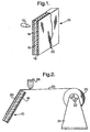
- FIG. 1 is a perspective view of a preferred embodiment of the armor panel according to the invention; and
- FIG. 2 is a diagrammatic view of a panel being wrapped by a continuous sheet.
- There is seen in FIG. 1 a composite, laminated
armor panel 10 for absorbing and dissipating kinetic energy from one or more projectiles 12.
A first outwardly positionedlayer 14 is made of a material having a Rockwell-C hardness of at least 27. Equivalent hardness is a Rockwell-A hardness of at least 63.8 and a Rockwell-D hardness of at least 45.2. - Suitable materials for the outwardly positioned
layer 14 include ceramic materials, for example zirconia-toughened ceramic and fiber-reinforced ceramics. Ceramic materials, which are not toughened, could be used for stationary applications but are not recommended for mobile use. Ceramics have advantages regarding low weight and resistance to high temperatures. - Suitable metals include titanium alloy, mainly for aircraft use, and hard carbon steel - a relatively low cost material - for general application. The primary advantage of metals is that they can more easily be fabricated to a required shape and size.
- The first outwardly positioned
layer 14 is bonded to anintermediate layer 16, which is softer than thefirst layer 14. Bonding method used depends on the composition of the two materials. - Suitable materials for the
intermediate layer 16 include aluminium alloys, magnesium alloys, low carbon steel, medium carbon steel and aluminium, in all cases having a Rockwell-C hardness of less than 27. This hardness is equivalent to a Rockwell-A hardness of less than 63.8 and a Rockwell-B hardness of less than 100. The softer metals are more ductile, and thus absorb energy over a greater distance when driven by a projectile. - The
intermediate layer 16 is bonded to a third, backinglayer 18 of tough woven textile material, preferably aramide synthetic fibers and polyethylene fibers. Suitable synthetic fibers are sold under trade names such as Dyneema® and Kevlar®. - The
panel 10 is then structurally wrapped bymaterial 20, as will be described with reference to FIG. 2. - Referring now to FIG. 2, there is seen the composite, laminated
armor panel 10 being structurally wrapped to prevent delamination in use. In the preferred embodiment shown, the wrappingmaterial 20 is a single continuous sheet, which forms an integral component of the panel. - The laminated 3-ply pane! is seen being wrapped on four sides in a further tough woven
textile material 20, which can be similar or identical to material used for construction of thethird backing layer 18. Thestructural wrapping material 20 is bonded to the outer surfaces of thepanel 10 while wrapping tension is maintained. Abrake 22 used on thefeed roll holder 24 can be used for this purpose. Application of anepoxy resin 26 is the preferred method of bonding thestructural wrapping material 20 to thepanel 10. - Advantageously all six sides of the
panel 10 are wrapped by subsequently rotating the panel 90 degrees and applying furtherstructural wrapping material 20. - The following ballistic test was carried out on a prototype panel made according to the present invention.
- A composite laminated armor panel was prepared having a first layer of Ti6Al4V 1.27 cm (0.5 inches) thick and having a Rockwell-C hardness of 34, a second intermediate layer of aluminium, 2.90 cm (1.14 inches) thick and having a Rockwell-B hardness of 54 and a third layer of Dyneema® having a thickness of 2.29 cm (0.9 inches).
- A polyurethane glue was applied in a thin coat to the interfacing surfaces of the three layers and then to the outer surfaces thereof, a three-ply Kevlar® woven textile material was wound around all sides of the composite panel which was then placed under pressure in a clamping device similar to that used for laminating Formica® to wood tabletops.
- The panel, having a size of 1 m by 1m, a weight of 161 kg and a thickness of 7.37 cm (2.9 inches) was repeatedly fired upon with 0.50 Ammunition at a distance of 13.5m. The panel was tested for the effect of multi-impact resistance to delamination. The panel was not tested for penetration or trauma at this time.
- Twenty-two rounds of 0.50 cal. ammunition were fired at said panel without any delamination being observed.
- It will be evident to those skilled in the art that the invention is not limited to the details of the foregoing illustrative embodiments and that the present invention may be embodied in other specific forms without departing from the scope of the invention as defined in the claims.
wherein said three layers are laminated together and wrapped on at least four sides in a further tough woven textile material which is bonded to the outer surfaces of said composite, laminated armor panel.
Claims (8)
- A composite, laminated armor panel (10) for absorbing and dissipating kinetic energy from projectiles, said panel comprising:a) a first outwardly-positioned layer (14) made of a hard material selected from a ceramic material and a metal having a Rockwell-C hardness of at least 27;b) an intermediate layer (16) softer than said first layer, made of a material selected from aluminium and metals having a Rockwell-C hardness of less than 27; andc) a third backing layer (18) of tough woven textile material;
characterised in that said three layers are laminated together and wrapped on at least four sides in a further tough woven textile material (20) which is bonded to the outer surface of said composite, laminated armor panel. - A composite, laminated armor panel (10) for absorbing and dissipating kinetic energy from projectiles, said panel comprising:a) a first outwardly-positioned layer (14) made of a hard material selected from a ceramic material and a metal having a Rockwell-C hardness of at least 27;b) an intermediate layer (16) softer than said first layer, made of a material selected from aluminium and metals having a Rockwell-C hardness of less than 27; andc) a third backing layer (18) of Dyneema;
characterised in that said three layers are laminated together and wrapped on at least four sides in a tough woven textile material (20) which is bonded to the outer surface of said composite, laminated armor panel. - A composite, laminated armor panel (10) according to claim 1 or claim 2, wherein said wrapping material (20) is a single continuous sheet.
- A composite, laminated armor panel (10) according to claim 1 or claim 2, wherein said first layer (14) is formed of a material selected from the group consisting of titanium, hard carbon steel and ceramics.
- A composite, laminated armor panel (10) according to claim 1 or claim 2, wherein said first layer (14) is selected from a material having a Rockwell-C hardness of at least 27, a Rockwell-A hardness of at least 63.8 and a Rockwell-D hardness of at least 45.2.
- A composite, laminated armor panel (10) according to claim 1 or claim 2, wherein said intermediate layer (16) is formed of a material selected from the group consisting of low carbon steel, medium carbon steel and aluminium.
- A composite, laminated armor panel (10) according to claim 1 or claim 2, wherein said intermediate layer (16) is formed of a material selected from a material having a Rockwell-C hardness of less than 27, a Rockwell-A hardness of less than 63.8 and a Rockwell-B hardness of less than 100.
- A composite, laminated armor panel (10) according to claim 1, wherein said tough woven textile material is selected from the group consisting of aramide synthetic fibers and polyethylene fibers.
Applications Claiming Priority (3)
| Application Number | Priority Date | Filing Date | Title |
|---|---|---|---|
| IL14090101A IL140901A (en) | 2001-01-15 | 2001-01-15 | Laminated armor |
| IL140901 | 2001-01-15 | ||
| PCT/IL2001/001053 WO2002055952A1 (en) | 2001-01-15 | 2001-11-14 | Laminated armor |
Publications (2)
| Publication Number | Publication Date |
|---|---|
| EP1352207A1 EP1352207A1 (en) | 2003-10-15 |
| EP1352207B1 true EP1352207B1 (en) | 2006-03-08 |
Family
ID=11075035
Family Applications (1)
| Application Number | Title | Priority Date | Filing Date |
|---|---|---|---|
| EP01273165A Revoked EP1352207B1 (en) | 2001-01-15 | 2001-11-14 | Laminated armor |
Country Status (9)
| Country | Link |
|---|---|
| US (1) | US6497966B2 (en) |
| EP (1) | EP1352207B1 (en) |
| AT (1) | ATE319976T1 (en) |
| AU (1) | AU2002223998B2 (en) |
| CA (1) | CA2431710C (en) |
| DE (1) | DE60117706T2 (en) |
| IL (1) | IL140901A (en) |
| NZ (1) | NZ526589A (en) |
| WO (1) | WO2002055952A1 (en) |
Families Citing this family (49)
| Publication number | Priority date | Publication date | Assignee | Title |
|---|---|---|---|---|
| US6912944B2 (en) * | 2001-07-25 | 2005-07-05 | Aceram Technologies, Inc. | Ceramic armour systems with a front spall layer and a shock absorbing layer |
| US7562612B2 (en) * | 2001-07-25 | 2009-07-21 | Aceram Materials & Technologies, Inc. | Ceramic components, ceramic component systems, and ceramic armour systems |
| US20050188831A1 (en) * | 2003-07-11 | 2005-09-01 | Us Global Nanospace, Inc. | Ballistic resistant turret and method of making same |
| IL157584A (en) * | 2003-08-26 | 2008-07-08 | Cohen Michael | Composite armor plate |
| IL158237A (en) * | 2003-10-02 | 2013-03-24 | Cohen Michael | Ceramic bodies for armor panel |
| US7540228B1 (en) | 2003-10-28 | 2009-06-02 | Strike Face Technology Incorporated | Ceramic armour and method of construction |
| KR20070057764A (en) | 2004-06-11 | 2007-06-07 | 스튜어트 앤드 스티븐슨 택티컬 비클 시스템스, 엘.피. | Armored cab for vehicles |
| US20090269552A1 (en) * | 2004-07-06 | 2009-10-29 | Composhield A/S | Armour plate |
| CA2483231C (en) * | 2004-09-30 | 2011-11-29 | Aceram Technologies Inc. | Ceramic armor system with diamond coating |
| US7383762B2 (en) * | 2005-04-03 | 2008-06-10 | Michael Cohen | Ceramic pellets and composite armor panel containing the same |
| US7661228B1 (en) | 2005-05-06 | 2010-02-16 | Kontek Industries, Inc. | Armored building modules and panels |
| US20070068377A1 (en) * | 2005-05-20 | 2007-03-29 | Pizhong Qiao | Hybrid composite structures for ballistic protection |
| IL169230A (en) † | 2005-06-16 | 2012-03-29 | Plasan Sasa Agricultural Cooperative Soc Ltd | Ballistic armor |
| US7389718B1 (en) | 2005-09-23 | 2008-06-24 | Carter Gerald D | Ballistic blanket |
| WO2008051200A2 (en) | 2005-09-27 | 2008-05-02 | Mti Acquisition Llc | Composite laminated armor structure |
| US7718245B2 (en) * | 2005-12-29 | 2010-05-18 | Honeywell International Inc. | Restrained breast plates, vehicle armored plates and helmets |
| US8058189B1 (en) | 2006-01-13 | 2011-11-15 | The United States Of America As Represented By The Secretary Of The Navy | Method and apparatus for resisting ballistic impact |
| US8028830B1 (en) * | 2006-01-13 | 2011-10-04 | The United States Of America As Represented By The Secretary Of The Navy | Anti-ballistic composite structure for ordinance |
| US7866248B2 (en) * | 2006-01-23 | 2011-01-11 | Intellectual Property Holdings, Llc | Encapsulated ceramic composite armor |
| US20070293107A1 (en) * | 2006-06-14 | 2007-12-20 | Hexcel Corporation | Composite assembly and methods of making and using the same |
| US8101272B1 (en) | 2006-06-16 | 2012-01-24 | United Technologies Corporation | Armor shell and fabrication methods |
| US7703375B1 (en) * | 2006-08-15 | 2010-04-27 | Lawrence Technological University | Composite armor with a cellular structure |
| US8689671B2 (en) | 2006-09-29 | 2014-04-08 | Federal-Mogul World Wide, Inc. | Lightweight armor and methods of making |
| IL179125A (en) | 2006-11-08 | 2012-10-31 | Moshe Ravid | Dual hardness armor |
| IL179592A (en) * | 2006-11-26 | 2012-03-29 | Moshe Ravid | Armor panel |
| US7790252B2 (en) * | 2007-01-12 | 2010-09-07 | Khosrow Nematollahi | Armoring device for protecting an object |
| US20080236378A1 (en) * | 2007-03-30 | 2008-10-02 | Intellectual Property Holdings, Llc | Affixable armor tiles |
| US8297177B2 (en) * | 2007-05-25 | 2012-10-30 | In The Line Of Fire Inc. | Ballistic projectile armour |
| US8087339B2 (en) * | 2007-07-24 | 2012-01-03 | Foster-Miller, Inc. | Armor system |
| US8052200B2 (en) * | 2007-10-31 | 2011-11-08 | Caterpillar Inc. | Vehicle cab floor protection system |
| US20100282062A1 (en) * | 2007-11-16 | 2010-11-11 | Intellectual Property Holdings, Llc | Armor protection against explosively-formed projectiles |
| EP2071272A3 (en) | 2007-12-11 | 2012-11-21 | Michael Cohen | Composite armor plate and method for using the same |
| US7979918B2 (en) * | 2008-02-14 | 2011-07-19 | Warrior Sports, Inc. | Protective covering |
| JP5508743B2 (en) * | 2009-03-12 | 2014-06-04 | 美濃窯業株式会社 | Shock absorbing member |
| US8334046B2 (en) * | 2009-05-12 | 2012-12-18 | E I Du Pont De Nemours And Company | Overmolded polyamide composite structures and processes for their preparation |
| US8342073B2 (en) | 2009-07-27 | 2013-01-01 | Battelle Energy Alliance, Llc | Composite armor, armor system and vehicle including armor system |
| US9194661B1 (en) * | 2009-08-11 | 2015-11-24 | Armorworks Enterprises, Llc | Ballistic armor assembly for vehicle-mounted explosive carrier |
| US20120291618A1 (en) * | 2009-10-27 | 2012-11-22 | Jay Clarke Hanan | Teardrop lattice structure for high specific strength materials |
| US8978536B2 (en) | 2012-04-30 | 2015-03-17 | Future Force Innovation, Inc. | Material for providing blast and projectile impact protection |
| US9919492B2 (en) * | 2013-03-15 | 2018-03-20 | Battelle Memorial Institute | Armor system with multi-hit capacity and method of manufacture |
| CN104848748B (en) * | 2015-05-15 | 2016-08-24 | 中国航空工业集团公司北京航空材料研究院 | A kind of lightweight armor armour and preparation method thereof |
| CN107310218B (en) | 2016-04-26 | 2019-03-29 | 宝山钢铁股份有限公司 | A kind of bulletproof composite steel plate and its manufacturing method |
| CN107310219B (en) | 2016-04-26 | 2019-03-29 | 宝山钢铁股份有限公司 | A kind of armour plate that clod wash processing performance is excellent and its manufacturing method |
| US20180073837A1 (en) * | 2016-09-12 | 2018-03-15 | Joel Bishara Bahu | Ballistic firearms container |
| DE102019116153A1 (en) * | 2019-06-13 | 2020-12-17 | Kennametal Inc. | Armor plate, armor plate composite and armor |
| CN111043909B (en) * | 2019-11-08 | 2022-03-15 | 中北大学 | Ti-Al intermetallic compound micro-laminated composite armor and preparation method thereof |
| RU197755U1 (en) * | 2019-12-02 | 2020-05-26 | Общество с ограниченной ответственностью "ТБ композит" | MULTILAYERED ARMOR |
| US11859952B1 (en) * | 2021-04-08 | 2024-01-02 | Ambitec Inc. | Armored plate assembly |
| US11415395B1 (en) | 2021-07-14 | 2022-08-16 | Corner Edge Technologies | Ballistic shield and method of manufacture |
Family Cites Families (9)
| Publication number | Priority date | Publication date | Assignee | Title |
|---|---|---|---|---|
| DE1584284B1 (en) * | 1965-07-23 | 1970-03-05 | Shwayder Warren Max | Armor plate |
| US4131053A (en) * | 1965-08-30 | 1978-12-26 | The United States Of America As Represented By The Secretary Of The Navy | Armor plate |
| GB1142689A (en) | 1966-03-29 | 1969-02-12 | Aerojet General Co | Armour plating |
| US4061815A (en) | 1967-10-26 | 1977-12-06 | The Upjohn Company | Novel compositions |
| GB1352418A (en) * | 1971-05-11 | 1974-05-08 | Feldmuehle Anlagen Prod | Armour plate |
| BE792805A (en) * | 1971-12-17 | 1973-03-30 | Feldmuehle Anlagen Prod | PROTECTIVE CLOTHING AGAINST PROJECTILES WITH HIGH KINETIC ENERGY |
| US4529640A (en) * | 1983-04-08 | 1985-07-16 | Goodyear Aerospace Corporation | Spaced armor |
| EP0287918A1 (en) * | 1987-04-13 | 1988-10-26 | Cemcom Corporation | Chemically bonded ceramic armor materials |
| US6112635A (en) | 1996-08-26 | 2000-09-05 | Mofet Etzion | Composite armor panel |
-
2001
- 2001-01-15 IL IL14090101A patent/IL140901A/en unknown
- 2001-11-14 AU AU2002223998A patent/AU2002223998B2/en not_active Ceased
- 2001-11-14 WO PCT/IL2001/001053 patent/WO2002055952A1/en active IP Right Grant
- 2001-11-14 NZ NZ52658901A patent/NZ526589A/en not_active IP Right Cessation
- 2001-11-14 EP EP01273165A patent/EP1352207B1/en not_active Revoked
- 2001-11-14 DE DE2001617706 patent/DE60117706T2/en not_active Expired - Lifetime
- 2001-11-14 AT AT01273165T patent/ATE319976T1/en active
- 2001-11-14 CA CA 2431710 patent/CA2431710C/en not_active Expired - Fee Related
- 2001-12-06 US US10/010,003 patent/US6497966B2/en not_active Expired - Lifetime
Also Published As
| Publication number | Publication date |
|---|---|
| CA2431710A1 (en) | 2002-07-18 |
| NZ526589A (en) | 2004-06-25 |
| IL140901A (en) | 2003-05-29 |
| DE60117706D1 (en) | 2006-05-04 |
| AU2002223998B2 (en) | 2007-01-04 |
| ATE319976T1 (en) | 2006-03-15 |
| DE60117706T2 (en) | 2006-11-02 |
| CA2431710C (en) | 2007-05-22 |
| WO2002055952A1 (en) | 2002-07-18 |
| IL140901A0 (en) | 2002-06-30 |
| EP1352207A1 (en) | 2003-10-15 |
| US20020094406A1 (en) | 2002-07-18 |
| US6497966B2 (en) | 2002-12-24 |
Similar Documents
| Publication | Publication Date | Title |
|---|---|---|
| EP1352207B1 (en) | Laminated armor | |
| AU2002223998A1 (en) | Laminated armor | |
| US7546796B2 (en) | Armor and method of making same | |
| US7562612B2 (en) | Ceramic components, ceramic component systems, and ceramic armour systems | |
| EP1409948B1 (en) | Ceramic armour systems with a front spall layer and a shock absorbing layer | |
| KR100529534B1 (en) | Ceramic bodies for use in composite armor | |
| EP0678724A1 (en) | Impact absorbing armor | |
| US20100212486A1 (en) | Ballistic armor panel system | |
| US7543523B2 (en) | Antiballistic armor | |
| US20090214812A1 (en) | Protective Composite Structures and Methods of Making Protective Composite Structures | |
| US9109858B1 (en) | Amphibious armor | |
| Ash | Vehicle armor | |
| CA2500619C (en) | Improved ceramic components, ceramic component systems, and ceramic armour systems | |
| CN216049450U (en) | Multilayer composite structure bulletproof armor for helicopter cockpit | |
| AU6744398A (en) | Composite armor panel | |
| NZ504079A (en) | Composite Armor Panel with high density ceramic pellets in rows bound and retained in plate form, ceramic pellets have an alumina content of at least 93% and at least one axis of 3mm in length |
Legal Events
| Date | Code | Title | Description |
|---|---|---|---|
| PUAI | Public reference made under article 153(3) epc to a published international application that has entered the european phase |
Free format text: ORIGINAL CODE: 0009012 |
|
| 17P | Request for examination filed |
Effective date: 20030625 |
|
| AK | Designated contracting states |
Kind code of ref document: A1 Designated state(s): AT BE CH CY DE DK ES FI FR GB GR IE IT LI LU MC NL PT SE TR |
|
| AX | Request for extension of the european patent |
Extension state: AL LT LV MK RO SI |
|
| 17Q | First examination report despatched |
Effective date: 20040212 |
|
| GRAP | Despatch of communication of intention to grant a patent |
Free format text: ORIGINAL CODE: EPIDOSNIGR1 |
|
| GRAS | Grant fee paid |
Free format text: ORIGINAL CODE: EPIDOSNIGR3 |
|
| GRAA | (expected) grant |
Free format text: ORIGINAL CODE: 0009210 |
|
| AK | Designated contracting states |
Kind code of ref document: B1 Designated state(s): AT BE CH CY DE DK ES FI FR GB GR IE IT LI LU MC NL PT SE TR |
|
| PG25 | Lapsed in a contracting state [announced via postgrant information from national office to epo] |
Ref country code: IT Free format text: LAPSE BECAUSE OF FAILURE TO SUBMIT A TRANSLATION OF THE DESCRIPTION OR TO PAY THE FEE WITHIN THE PRESCRIBED TIME-LIMIT;WARNING: LAPSES OF ITALIAN PATENTS WITH EFFECTIVE DATE BEFORE 2007 MAY HAVE OCCURRED AT ANY TIME BEFORE 2007. THE CORRECT EFFECTIVE DATE MAY BE DIFFERENT FROM THE ONE RECORDED. Effective date: 20060308 Ref country code: CH Free format text: LAPSE BECAUSE OF FAILURE TO SUBMIT A TRANSLATION OF THE DESCRIPTION OR TO PAY THE FEE WITHIN THE PRESCRIBED TIME-LIMIT Effective date: 20060308 Ref country code: FI Free format text: LAPSE BECAUSE OF FAILURE TO SUBMIT A TRANSLATION OF THE DESCRIPTION OR TO PAY THE FEE WITHIN THE PRESCRIBED TIME-LIMIT Effective date: 20060308 Ref country code: NL Free format text: LAPSE BECAUSE OF FAILURE TO SUBMIT A TRANSLATION OF THE DESCRIPTION OR TO PAY THE FEE WITHIN THE PRESCRIBED TIME-LIMIT Effective date: 20060308 Ref country code: BE Free format text: LAPSE BECAUSE OF FAILURE TO SUBMIT A TRANSLATION OF THE DESCRIPTION OR TO PAY THE FEE WITHIN THE PRESCRIBED TIME-LIMIT Effective date: 20060308 Ref country code: LI Free format text: LAPSE BECAUSE OF FAILURE TO SUBMIT A TRANSLATION OF THE DESCRIPTION OR TO PAY THE FEE WITHIN THE PRESCRIBED TIME-LIMIT Effective date: 20060308 |
|
| REG | Reference to a national code |
Ref country code: GB Ref legal event code: FG4D |
|
| REG | Reference to a national code |
Ref country code: CH Ref legal event code: EP |
|
| REG | Reference to a national code |
Ref country code: IE Ref legal event code: FG4D |
|
| REF | Corresponds to: |
Ref document number: 60117706 Country of ref document: DE Date of ref document: 20060504 Kind code of ref document: P |
|
| PG25 | Lapsed in a contracting state [announced via postgrant information from national office to epo] |
Ref country code: SE Free format text: LAPSE BECAUSE OF FAILURE TO SUBMIT A TRANSLATION OF THE DESCRIPTION OR TO PAY THE FEE WITHIN THE PRESCRIBED TIME-LIMIT Effective date: 20060608 Ref country code: DK Free format text: LAPSE BECAUSE OF FAILURE TO SUBMIT A TRANSLATION OF THE DESCRIPTION OR TO PAY THE FEE WITHIN THE PRESCRIBED TIME-LIMIT Effective date: 20060608 |
|
| PG25 | Lapsed in a contracting state [announced via postgrant information from national office to epo] |
Ref country code: ES Free format text: LAPSE BECAUSE OF FAILURE TO SUBMIT A TRANSLATION OF THE DESCRIPTION OR TO PAY THE FEE WITHIN THE PRESCRIBED TIME-LIMIT Effective date: 20060619 |
|
| PG25 | Lapsed in a contracting state [announced via postgrant information from national office to epo] |
Ref country code: PT Free format text: LAPSE BECAUSE OF FAILURE TO SUBMIT A TRANSLATION OF THE DESCRIPTION OR TO PAY THE FEE WITHIN THE PRESCRIBED TIME-LIMIT Effective date: 20060808 |
|
| NLV1 | Nl: lapsed or annulled due to failure to fulfill the requirements of art. 29p and 29m of the patents act | ||
| REG | Reference to a national code |
Ref country code: CH Ref legal event code: PL |
|
| ET | Fr: translation filed | ||
| PG25 | Lapsed in a contracting state [announced via postgrant information from national office to epo] |
Ref country code: IE Free format text: LAPSE BECAUSE OF NON-PAYMENT OF DUE FEES Effective date: 20061114 |
|
| PG25 | Lapsed in a contracting state [announced via postgrant information from national office to epo] |
Ref country code: MC Free format text: LAPSE BECAUSE OF NON-PAYMENT OF DUE FEES Effective date: 20061130 |
|
| PLBI | Opposition filed |
Free format text: ORIGINAL CODE: 0009260 |
|
| PLAX | Notice of opposition and request to file observation + time limit sent |
Free format text: ORIGINAL CODE: EPIDOSNOBS2 |
|
| 26 | Opposition filed |
Opponent name: PLASAN-SASA - LIMITED PARTNERSHIP OF KIBBUTZ SASA Effective date: 20061208 |
|
| PLAF | Information modified related to communication of a notice of opposition and request to file observations + time limit |
Free format text: ORIGINAL CODE: EPIDOSCOBS2 |
|
| PLBB | Reply of patent proprietor to notice(s) of opposition received |
Free format text: ORIGINAL CODE: EPIDOSNOBS3 |
|
| PG25 | Lapsed in a contracting state [announced via postgrant information from national office to epo] |
Ref country code: GR Free format text: LAPSE BECAUSE OF FAILURE TO SUBMIT A TRANSLATION OF THE DESCRIPTION OR TO PAY THE FEE WITHIN THE PRESCRIBED TIME-LIMIT Effective date: 20060609 |
|
| PG25 | Lapsed in a contracting state [announced via postgrant information from national office to epo] |
Ref country code: LU Free format text: LAPSE BECAUSE OF NON-PAYMENT OF DUE FEES Effective date: 20061114 Ref country code: TR Free format text: LAPSE BECAUSE OF FAILURE TO SUBMIT A TRANSLATION OF THE DESCRIPTION OR TO PAY THE FEE WITHIN THE PRESCRIBED TIME-LIMIT Effective date: 20060308 |
|
| PG25 | Lapsed in a contracting state [announced via postgrant information from national office to epo] |
Ref country code: CY Free format text: LAPSE BECAUSE OF FAILURE TO SUBMIT A TRANSLATION OF THE DESCRIPTION OR TO PAY THE FEE WITHIN THE PRESCRIBED TIME-LIMIT Effective date: 20060308 |
|
| PLAY | Examination report in opposition despatched + time limit |
Free format text: ORIGINAL CODE: EPIDOSNORE2 |
|
| PLBC | Reply to examination report in opposition received |
Free format text: ORIGINAL CODE: EPIDOSNORE3 |
|
| PLAB | Opposition data, opponent's data or that of the opponent's representative modified |
Free format text: ORIGINAL CODE: 0009299OPPO |
|
| R26 | Opposition filed (corrected) |
Opponent name: PLASAN-SASA - LIMITED PARTNERSHIP OF KIBBUTZ SASA Effective date: 20061208 |
|
| REG | Reference to a national code |
Ref country code: FR Ref legal event code: PLFP Year of fee payment: 15 |
|
| REG | Reference to a national code |
Ref country code: FR Ref legal event code: PLFP Year of fee payment: 16 |
|
| PLAY | Examination report in opposition despatched + time limit |
Free format text: ORIGINAL CODE: EPIDOSNORE2 |
|
| PGFP | Annual fee paid to national office [announced via postgrant information from national office to epo] |
Ref country code: FR Payment date: 20161024 Year of fee payment: 16 Ref country code: DE Payment date: 20161020 Year of fee payment: 16 Ref country code: GB Payment date: 20161027 Year of fee payment: 16 |
|
| PGFP | Annual fee paid to national office [announced via postgrant information from national office to epo] |
Ref country code: AT Payment date: 20161021 Year of fee payment: 16 |
|
| PLBC | Reply to examination report in opposition received |
Free format text: ORIGINAL CODE: EPIDOSNORE3 |
|
| RDAF | Communication despatched that patent is revoked |
Free format text: ORIGINAL CODE: EPIDOSNREV1 |
|
| STAA | Information on the status of an ep patent application or granted ep patent |
Free format text: STATUS: THE PATENT HAS BEEN GRANTED |
|
| REG | Reference to a national code |
Ref country code: DE Ref legal event code: R064 Ref document number: 60117706 Country of ref document: DE Ref country code: DE Ref legal event code: R103 Ref document number: 60117706 Country of ref document: DE |
|
| RDAG | Patent revoked |
Free format text: ORIGINAL CODE: 0009271 |
|
| STAA | Information on the status of an ep patent application or granted ep patent |
Free format text: STATUS: PATENT REVOKED |
|
| 27W | Patent revoked |
Effective date: 20170414 |
|
| GBPR | Gb: patent revoked under art. 102 of the ep convention designating the uk as contracting state |
Effective date: 20170414 |
|
| REG | Reference to a national code |
Ref country code: AT Ref legal event code: MA03 Ref document number: 319976 Country of ref document: AT Kind code of ref document: T Effective date: 20170414 |
|
| STAA | Information on the status of an ep patent application or granted ep patent |
Free format text: STATUS: PATENT REVOKED |