EP1353402A1 - Modular antenna system - Google Patents
Modular antenna system Download PDFInfo
- Publication number
- EP1353402A1 EP1353402A1 EP03100924A EP03100924A EP1353402A1 EP 1353402 A1 EP1353402 A1 EP 1353402A1 EP 03100924 A EP03100924 A EP 03100924A EP 03100924 A EP03100924 A EP 03100924A EP 1353402 A1 EP1353402 A1 EP 1353402A1
- Authority
- EP
- European Patent Office
- Prior art keywords
- antenna
- antennas
- satcom
- antenna system
- gatelink
- Prior art date
- Legal status (The legal status is an assumption and is not a legal conclusion. Google has not performed a legal analysis and makes no representation as to the accuracy of the status listed.)
- Withdrawn
Links
Images

Classifications
-
- H—ELECTRICITY
- H01—ELECTRIC ELEMENTS
- H01Q—ANTENNAS, i.e. RADIO AERIALS
- H01Q3/00—Arrangements for changing or varying the orientation or the shape of the directional pattern of the waves radiated from an antenna or antenna system
-
- H—ELECTRICITY
- H01—ELECTRIC ELEMENTS
- H01Q—ANTENNAS, i.e. RADIO AERIALS
- H01Q1/00—Details of, or arrangements associated with, antennas
- H01Q1/27—Adaptation for use in or on movable bodies
- H01Q1/28—Adaptation for use in or on aircraft, missiles, satellites, or balloons
-
- H—ELECTRICITY
- H01—ELECTRIC ELEMENTS
- H01Q—ANTENNAS, i.e. RADIO AERIALS
- H01Q21/00—Antenna arrays or systems
- H01Q21/28—Combinations of substantially independent non-interacting antenna units or systems
-
- H—ELECTRICITY
- H04—ELECTRIC COMMUNICATION TECHNIQUE
- H04B—TRANSMISSION
- H04B7/00—Radio transmission systems, i.e. using radiation field
- H04B7/14—Relay systems
- H04B7/15—Active relay systems
- H04B7/185—Space-based or airborne stations; Stations for satellite systems
- H04B7/18502—Airborne stations
- H04B7/18506—Communications with or from aircraft, i.e. aeronautical mobile service
- H04B7/18508—Communications with or from aircraft, i.e. aeronautical mobile service with satellite system used as relay, i.e. aeronautical mobile satellite service
Definitions
- the present invention relates in particular to an integrated avionics modular antenna system, comprising at least two directional antennas capable of operating in different frequency bands B 1 , B 2 .
- the carrier is for example a ship, an airplane or a car.
- the antenna that is used preference is the dipole antenna, some practical achievements of which are: whip antenna, quarter wave antenna, fin antenna, integrated antenna portable telephones.
- Such an antenna has the advantages, for example, to be of a small footprint for frequencies beyond 1 GHz and to be quasi-omnidirectional, that is to say not to require pointing device.
- the dipole antenna also has certain drawbacks, in particular, to be polluting on emission (it emits a signal to all receivers in addition to the useful receiver) and to be non-discriminating in reception (it receives all transmitters in addition to the useful transmitter).
- the dipole antenna thus contributes to a waste of the frequency resource.
- Directional antennas are more easily used in fixed applications.
- each system is associated an antenna.
- concentration of branches and their collocation lead in particular to a critical drop in performance.
- the number and arrangement of antennas current practically prohibits the installation of additional antennas.
- the subject of the invention relates to an antenna system intended to be installed for example on a mobile carrier.
- This antenna system includes at least two directional antennas working in different fields frequency.
- the antenna system performs the function of several antennas, for example the function of three directional antennas, in a volume and easements equivalent to those usually required for an antenna.
- the object of the invention relates to a characterized antenna system in that it comprises at least three directional antennas, one antenna Gatelink, a Satcom Ku antenna, a Satcom Inmarsat antenna, the said antennas being arranged on a mobile support in rotation and / or in translation and an antenna protection device.
- the protection of the antennas is for example ensured by a radome.
- the invention also relates to a telecommunications system. characterized in that it comprises at least one antenna system having one of the above characteristics and at least one pointing device antenna, in connection with an inertial unit, as well as a transceiver .
- the invention is used for example to equip the fuselage with a airliner.
- the antenna system object of the present invention, offers in particular as an advantage of integrating several directive antennas in a reduced size system.
- an airliner equipped for example with an antenna system comprising at least three directional antennas.
- Each antenna is intended for example for a given application, such as Inmarsat, Ku Band and Gatelink.
- the three applications operate in three different frequency bands F 1 , F 2, F 3 and the three antennas are not activated at the same time.
- the antenna system also includes a radome 6 arranged to so as to cover all the antennas installed in order to protect them.
- a radio block 7 known to those skilled in the art performs the radio functions of proximity to the various antennas. For example, it performs the functions power amplifier, low noise amplification, filters, duplexer. This radio block is for example optimized as a function of the implementation of antennas in the antenna system.
- the three antennas, Gatelink 1, Satcom Ku 2 and Inmarsat 3 are, for example, arranged without opposite to emit to the sides without interfere with each other, for example according to a diagram as shown in figure 1. They form a triangle, with the radio block 7 placed in the center. In such a configuration, they leave a gray area in the center of the antenna system, shadow area in which the antenna is placed GPS.
- the usual precautions and known to the skilled person, for the implementation of the antennas, can be found partly in the ARINC 761 standard and are respected.
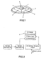
- Figure 2 shows an example of a block diagram of a telecommunications installed on an airliner, for example, including the antenna system according to the invention in connection with the aircraft.
- a description detailed synoptic can be found in ARINC 741.
- the antenna system receives pointing information delivered by an antenna pointer 9 which is connected to an inertial unit 10.
- An integrated transceiver 8 by example, is in connection with an Ethernet 11 network, speech, etc. and dialogue with the antenna system A.
- the inertial unit 10 or any suitable device allows including obtaining a statement of geographic position, orientation and the altitude of the aircraft.
- the antenna pointer 9 controls the selection of the antenna and the orientation of the positioner as a function for example of the position, the orientation and altitude of the aircraft, communicated by the central inertial, and as a function, for example, of the supposedly known direction of the radio link required.
- the pointer will activate by example Gatelink antenna 1 if the plane is on the ground at the airport, antenna 2 Satcom Ku if the aircraft is in flight over a continental area served by a Ku satellite, the 3 INMARSAT antenna if the airplane is in flight over a maritime area not served by a Ku satellite. Satellite positions Ku and Inmarsat are known with sufficient precision to allow a direct pointing of the antenna with the necessary precision.
- positions are recorded, for example, in the memory of the antenna pointer.
- An example of pointing to INMARSAT satellites, transposable to Ku satellites, is given in ARINC 741.
- the position and orientation of an airplane parked on a airport is known in advance and this data is stored in the pointer memory with point position information radio access to the airport.
- a scanning system in antenna azimuth (scanning) can be implemented to compensate in case these data are not known or obsolete.
- the integrated transceiver 8 performs, for example, in a same equipment, all telecommunications functions associated with the invention. It is connected to the on-board network through interfaces given standards, such as Ethernet, speech, etc.
Abstract
Description
La présente invention concerne notamment un système antennaire modulaire avionique intégré, comportant au moins deux antennes directives susceptibles de fonctionner dans des bandes de fréquence différentes B1, B2.The present invention relates in particular to an integrated avionics modular antenna system, comprising at least two directional antennas capable of operating in different frequency bands B 1 , B 2 .
Elle s'applique plus particulièrement sur tout porteur mobile équipé de plusieurs antennes directives fonctionnant par exemple dans des gammes de fréquence différentes et devant être située dans un espacement limité. Le porteur est par exemple un navire, un avion ou une voiture.It applies more particularly to any mobile carrier equipped of several directional antennas operating for example in ranges of different frequency and to be located in a limited space. The carrier is for example a ship, an airplane or a car.
Dans les applications mobiles, l'antenne qui est utilisée de préférence est l'antenne dipôle, dont quelques réalisations pratiques sont : l'antenne fouet, l'antenne quart d'onde, l'antenne aileron, l'antenne intégrée des téléphones portatifs. Une telle antenne présente comme avantages, par exemple, d'être d'un faible encombrement pour les fréquences au-delà de 1 GHz et d'être quasi-omnidirectionnelle, c'est-à-dire de ne pas nécessiter de dispositif de pointage.In mobile applications, the antenna that is used preference is the dipole antenna, some practical achievements of which are: whip antenna, quarter wave antenna, fin antenna, integrated antenna portable telephones. Such an antenna has the advantages, for example, to be of a small footprint for frequencies beyond 1 GHz and to be quasi-omnidirectional, that is to say not to require pointing device.
Toutefois, l'antenne dipôle présente aussi certains inconvénients, notamment, d'être polluante à l'émission (elle émet un signal vers tous les récepteurs en sus du récepteur utile) et d'être non discriminante en réception (elle reçoit tous les émetteurs en sus de l'émetteur utile). De plus, en raison de sa petite taille, elle est peu sensible et demande des puissances d'émission importantes. L'antenne dipôle contribue ainsi à un gaspillage de la ressource fréquence. Les antennes directives sont plus facilement utilisées dans des applications fixes.However, the dipole antenna also has certain drawbacks, in particular, to be polluting on emission (it emits a signal to all receivers in addition to the useful receiver) and to be non-discriminating in reception (it receives all transmitters in addition to the useful transmitter). In addition, due of its small size, it is not very sensitive and requires powers significant emissions. The dipole antenna thus contributes to a waste of the frequency resource. Directional antennas are more easily used in fixed applications.
La croissance des besoins en radiocommunications conduit à déployer plusieurs systèmes radio sur les porteurs, à chaque système est associée une antenne. La concentration des antennes et leur collocation induisent notamment une baisse critique des performances. Dans le cas des avions de ligne, par exemple, le nombre et la disposition des antennes actuelles interdit pratiquement l'installation d'antennes supplémentaires. The growth in radiocommunication needs leads to deploy multiple radio systems on carriers, each system is associated an antenna. The concentration of branches and their collocation lead in particular to a critical drop in performance. In the case of airliners, for example, the number and arrangement of antennas current practically prohibits the installation of additional antennas.
Aujourd'hui, pour les applications mobiles, on dispose par exemple, de bandes réservées permettant l'utilisation d'antennes peu directives. C'est le cas du système INMARSAT, déployé en bande L, et du futur système AIRTV, déployé en bande S. La ressource fréquence allouée à ces systèmes reste néanmoins marginale et leur capacité est handicapée par la faible sélectivité des antennes.Today, for mobile applications, we have example, of reserved bands allowing the use of antennas little guidelines. This is the case with the INMARSAT system, deployed in L-band, and the future AIRTV system, deployed in S band. The frequency resource allocated to these systems nevertheless remain marginal and their capacity is handicapped by the low selectivity of the antennas.
L'objet de l'invention a trait à un système antennaire destiné à être installé par exemple sur un porteur mobile. Ce système antennaire comporte au moins deux antennes directives travaillant dans des domaines différents de fréquence.The subject of the invention relates to an antenna system intended to be installed for example on a mobile carrier. This antenna system includes at least two directional antennas working in different fields frequency.
Le système antennaire réalise la fonction de plusieurs antennes, par exemple la fonction de trois antennes directives, dans un volume et des servitudes équivalents à ceux habituellement nécessaires à une antenne.The antenna system performs the function of several antennas, for example the function of three directional antennas, in a volume and easements equivalent to those usually required for an antenna.
L'objet de l'invention concerne un système antennaire caractérisé en ce qu'il comporte au moins trois antennes directives, une antenne Gatelink, une antenne Satcom Ku, une antenne Satcom Inmarsat, lesdites antennes étant disposées sur un support mobile en rotation et/ou en translation et un dispositif de protection des antennes.The object of the invention relates to a characterized antenna system in that it comprises at least three directional antennas, one antenna Gatelink, a Satcom Ku antenna, a Satcom Inmarsat antenna, the said antennas being arranged on a mobile support in rotation and / or in translation and an antenna protection device.
La protection des antennes est par exemple assurée par un radôme.The protection of the antennas is for example ensured by a radome.
Il peut comporter en plus une antenne de type GPS.It can also include a GPS type antenna.
L'invention concerne aussi un système de télécommunication caractérisé en ce qu'il comporte au moins un système antennaire présentant l'une des caractéristiques précitées et au moins un dispositif de pointage d'antenne, en liaison avec une centrale inertielle, ainsi qu'un émetteur-récepteur .The invention also relates to a telecommunications system. characterized in that it comprises at least one antenna system having one of the above characteristics and at least one pointing device antenna, in connection with an inertial unit, as well as a transceiver .
L'invention est utilisée par exemple pour équiper le fuselage d'un avion de ligne.The invention is used for example to equip the fuselage with a airliner.
Le système antennaire, objet de la présente invention, offre notamment comme avantage d'intégrer plusieurs antennes directives dans un système de taille réduite. The antenna system, object of the present invention, offers in particular as an advantage of integrating several directive antennas in a reduced size system.
D'autres caractéristiques et avantages du système antennaire
selon l'invention apparaítront mieux à la lecture de la description annexée
des figures qui représentent
De manière à mieux faire comprendre l'objet de la présente invention, la description qui suit, donnée à titre illustratif et nullement limitatif, concerne un avion de ligne équipé par exemple d'un système antennaire comportant au moins trois antennes directives. Chaque antenne est destinée par exemple à une application donnée, telle que Inmarsat, Ku Band et Gatelink. Les trois applications fonctionnent dans trois bandes de fréquence différentes F1, F2, F3 et les trois antennes ne sont pas activées en même temps.In order to better understand the object of the present invention, the following description, given by way of illustration and in no way limiting, relates to an airliner equipped for example with an antenna system comprising at least three directional antennas. Each antenna is intended for example for a given application, such as Inmarsat, Ku Band and Gatelink. The three applications operate in three different frequency bands F 1 , F 2, F 3 and the three antennas are not activated at the same time.
La figure 1 représente un exemple de système antennaire
modulaire intégré selon l'invention, comportant un positionneur 5 constitué
par exemple d'un plateau tournant motorisé. Le positionneur permet
l'orientation sur un axe en azimut des antennes qu'il supporte. Il peut être
mobile en rotation et/ou en translation. Dans ce cas il est équipé d'un
dispositif non représenté qui permet de réaliser les mouvements de rotation
et de translation. Les 3 antennes couvrent par exemple les services pour un
avion de ligne et sont :
Les dispositifs permettant l'orientation mécanique ou électronique des
antennes sont connus de l'Homme du métier et n'étant pas l'objet de
l'invention, ils ne seront pas détaillés.
Le système antennaire comporte aussi un radôme 6 disposé de
façon à couvrir la totalité des antennes installées afin de les protéger. Un
bloc radio 7 connu de l'Homme du métier assure les fonctions radio de
proximité avec les différentes antennes. Par exemple, il remplit les fonctions
d'amplificateur de puissance, d'amplification faible bruit, de filtres, de
duplexeur. Ce bloc radio est par exemple optimisé en fonction de
l'implémentation des antennes dans le système antennaire.The antenna system also includes a
Les trois antennes, Gatelink 1, Satcom Ku 2 et Inmarsat 3 sont,
par exemple, disposées sans vis à vis pour émettre vers les côtés sans
interférer entre elles, selon par exemple un schéma tel que représenté à la
figure 1. Elles forment un triangle, avec le bloc radio 7 disposé au centre.
Dans une telle configuration, elles laissent une zone d'ombre au centre du
système antennaire, zone d'ombre dans laquelle est disposée l'antenne
GPS. Les précautions d'usage habituelles et connues de l'Homme du métier,
pour l'implémentation des antennes, peuvent être trouvées en partie dans la
norme ARINC 761 et sont respectées.The three antennas, Gatelink 1,
Les servitudes nécessaires au fonctionnement de l'ensemble, par exemple les alimentations, le refroidissement, etc., ne sont pas détaillées car elles ne sont pas l'objet de l'invention.The easements necessary for the operation of the whole, for example power supplies, cooling, etc., are not detailed because they are not the subject of the invention.
La figure 2 montre un exemple de synoptique d'un système de télécommunication installé sur un avion de ligne, par exemple, comprenant le système antennaire selon l'invention en liaison avec l'avion. Une description détaillée du synoptique peut être trouvée dans l'ARINC 741.Figure 2 shows an example of a block diagram of a telecommunications installed on an airliner, for example, including the antenna system according to the invention in connection with the aircraft. A description detailed synoptic can be found in ARINC 741.
Le système antennaire, représenté par le bloc A sur la figure,
reçoit une information de pointage délivrée par un pointeur d'antenne 9 qui
est relié à une centrale inertielle 10. Un émetteur-récepteur intégré 8, par
exemple, est en liaison avec un réseau 11 Ethernet, phonie, etc. et dialogue
avec le système antennaire A.The antenna system, represented by block A in the figure,
receives pointing information delivered by an
La centrale inertielle 10 ou tout dispositif adapté permet
notamment d'obtenir le relevé de la position géographique, l'orientation et
l'altitude de l'avion.The
Le pointeur d'antenne 9 pilote la sélection de l'antenne et
l'orientation du positionneur en fonction par exemple de la position, de
l'orientation et de l'altitude de l'avion, communiquées par la centrale
inertielle, et en fonction, par exemple, de la direction supposée connue de la
liaison radio requise. Dans le cas d'un avion de ligne, le pointeur activera par
exemple l'antenne 1 Gatelink si l'avion est au sol à l'aéroport, l'antenne 2
Satcom Ku si l'avion est en vol au-dessus d'une zone continentale servie par
un satellite Ku, l'antenne 3 INMARSAT si l'avion est en vol au-dessus d'une
zone maritime non desservie par un satellite Ku. Les positions des satellites
Ku et Inmarsat sont connues avec une précision suffisante pour permettre un
pointage direct de l'antenne avec la précision nécessaire. Ces positions sont
inscrites, par exemple, dans la mémoire du pointeur d'antenne. Un exemple
d'implémentation du pointage vers les satellites INMARSAT, transposable
aux satellites Ku, est donnée dans l'ARINC 741. Au sol à l'aéroport, selon le
même principe, la position et l'orientation d'un avion en parking sur un
aéroport est connue à l'avance et ces données sont stockées dans la
mémoire du pointeur avec les informations relatives à la position des points
d'accès radio sur l'aéroport. Un système d'acquisition par balayage en
azimut de l'antenne (scanning) peut être implémenté pour palier au cas où
ces données ne sont pas connues ou obsolètes.The
L'émetteur-récepteur intégré 8 réalise, par exemple, dans un même équipement, toutes les fonctions de télécommunications associées à l'invention. Il est raccordé au réseau de bord au travers des interfaces standards données, tels que l'Ethernet, la phonie, etc.The integrated transceiver 8 performs, for example, in a same equipment, all telecommunications functions associated with the invention. It is connected to the on-board network through interfaces given standards, such as Ethernet, speech, etc.
La figure 3 schématise un exemple d'installation d'une antenne
selon l'invention sur un avion de ligne. Le système antennaire référencé 16
est installé par exemple sur le fuselage de l'avion. Le système permet
notamment à l'avion de :
Claims (6)
Applications Claiming Priority (2)
| Application Number | Priority Date | Filing Date | Title |
|---|---|---|---|
| FR0204405 | 2002-04-09 | ||
| FR0204405A FR2838243B1 (en) | 2002-04-09 | 2002-04-09 | MODULAR ANTENNA SYSTEM |
Publications (1)
| Publication Number | Publication Date |
|---|---|
| EP1353402A1 true EP1353402A1 (en) | 2003-10-15 |
Family
ID=28052232
Family Applications (1)
| Application Number | Title | Priority Date | Filing Date |
|---|---|---|---|
| EP03100924A Withdrawn EP1353402A1 (en) | 2002-04-09 | 2003-04-07 | Modular antenna system |
Country Status (4)
| Country | Link |
|---|---|
| US (1) | US6831610B2 (en) |
| EP (1) | EP1353402A1 (en) |
| CA (1) | CA2424528A1 (en) |
| FR (1) | FR2838243B1 (en) |
Cited By (2)
| Publication number | Priority date | Publication date | Assignee | Title |
|---|---|---|---|---|
| FR2914787A1 (en) * | 2007-04-03 | 2008-10-10 | Thales Sa | ANTENNA SYSTEM FOR MOBILE CARRIER |
| EP3796572A1 (en) * | 2019-09-18 | 2021-03-24 | Rockwell Collins, Inc. | Hybrid satellite communication system for cockpit, cabin, and crew connectivity |
Families Citing this family (15)
| Publication number | Priority date | Publication date | Assignee | Title |
|---|---|---|---|---|
| US6977618B1 (en) * | 2003-12-05 | 2005-12-20 | L3 Communications Corporation | Aircraft folding antenna assembly |
| US7967252B2 (en) * | 2004-01-16 | 2011-06-28 | The Boeing Company | Fairing and airfoil apparatus and method |
| US7967253B2 (en) * | 2004-01-16 | 2011-06-28 | The Boeing Company | Antenna fairing and method |
| US7068235B2 (en) * | 2004-07-26 | 2006-06-27 | Row 44, Llc | Antenna system |
| ATE393974T1 (en) * | 2004-11-04 | 2008-05-15 | Spacecom Holding Aps | ANTENNA ASSEMBLY AND METHOD FOR SATELLITE TRACKING |
| US7359703B2 (en) * | 2005-02-09 | 2008-04-15 | Honeywell International Inc. | Adaptive communications system and method |
| US9246207B2 (en) * | 2005-09-22 | 2016-01-26 | Purdue Research Foundation | Antenna aiming system and method for broadband wireless access |
| US20080100517A1 (en) * | 2006-10-27 | 2008-05-01 | Shaver Brian D | Internet communication system |
| US20080106482A1 (en) * | 2006-11-08 | 2008-05-08 | Alan Cherrette | Electronically scanned hemispheric antenna |
| US8170988B2 (en) * | 2008-04-17 | 2012-05-01 | The Boeing Company | System and method for synchronizing databases |
| US8437906B2 (en) | 2008-04-17 | 2013-05-07 | The Boeing Company | System and method for generating maintenance release information |
| US9016631B2 (en) * | 2012-04-09 | 2015-04-28 | R4 Integration, Inc. | Multi-purpose hatch system |
| US10566683B1 (en) | 2016-06-10 | 2020-02-18 | Rockwell Collins, Inc. | System and method for an aircraft communicating with multiple satellite constellations |
| FR3055743B1 (en) * | 2016-09-08 | 2018-09-14 | Airbus Operations Sas | AIRCRAFT RADOME COMPRISING A WIFI ANTENNA |
| US10581147B1 (en) | 2017-01-23 | 2020-03-03 | Rockwell Collins, Inc. | Arbitrary polarization circular and cylindrical antenna arrays |
Citations (5)
| Publication number | Priority date | Publication date | Assignee | Title |
|---|---|---|---|---|
| US5678171A (en) * | 1992-11-30 | 1997-10-14 | Nippon Hoso Kyokai | Mobile receiver for satellite broadcast during flight |
| US6023245A (en) * | 1998-08-10 | 2000-02-08 | Andrew Corporation | Multi-band, multiple purpose antenna particularly useful for operation in cellular and global positioning system modes |
| US6175340B1 (en) * | 1998-05-04 | 2001-01-16 | Motorola, Inc. | Hybrid geostationary and low earth orbit satellite ground station antenna |
| US6195060B1 (en) * | 1999-03-09 | 2001-02-27 | Harris Corporation | Antenna positioner control system |
| EP1143556A1 (en) * | 2000-04-07 | 2001-10-10 | Diehl Munitionssysteme GmbH & Co. KG | Projectile with antenna for a satellite navigation receiver |
Family Cites Families (1)
| Publication number | Priority date | Publication date | Assignee | Title |
|---|---|---|---|---|
| US6741841B1 (en) * | 2000-01-28 | 2004-05-25 | Rockwell Collins | Dual receiver for a on-board entertainment system |
-
2002
- 2002-04-09 FR FR0204405A patent/FR2838243B1/en not_active Expired - Fee Related
-
2003
- 2003-04-07 CA CA002424528A patent/CA2424528A1/en not_active Abandoned
- 2003-04-07 EP EP03100924A patent/EP1353402A1/en not_active Withdrawn
- 2003-04-08 US US10/408,660 patent/US6831610B2/en not_active Expired - Fee Related
Patent Citations (5)
| Publication number | Priority date | Publication date | Assignee | Title |
|---|---|---|---|---|
| US5678171A (en) * | 1992-11-30 | 1997-10-14 | Nippon Hoso Kyokai | Mobile receiver for satellite broadcast during flight |
| US6175340B1 (en) * | 1998-05-04 | 2001-01-16 | Motorola, Inc. | Hybrid geostationary and low earth orbit satellite ground station antenna |
| US6023245A (en) * | 1998-08-10 | 2000-02-08 | Andrew Corporation | Multi-band, multiple purpose antenna particularly useful for operation in cellular and global positioning system modes |
| US6195060B1 (en) * | 1999-03-09 | 2001-02-27 | Harris Corporation | Antenna positioner control system |
| EP1143556A1 (en) * | 2000-04-07 | 2001-10-10 | Diehl Munitionssysteme GmbH & Co. KG | Projectile with antenna for a satellite navigation receiver |
Non-Patent Citations (2)
| Title |
|---|
| PANKOW R J: "Integrating a radar/ESM antenna suite with the S-70 helicopter", TRW, 14 October 1991 (1991-10-14), pages 539 - 543, XP010093748 * |
| PAPAVRAMIDIS A C ET AL: "Adaptation of land mobile systems for onboard operation", UNIVERSAL PERSONAL COMMUNICATIONS, 1993. PERSONAL COMMUNICATIONS: GATEWAY TO THE 21ST CENTURY. CONFERENCE RECORD., 2ND INTERNATIONAL CONFERENCE ON OTTAWA, ONT., CANADA 12-15 OCT. 1993, NEW YORK, NY, USA,IEEE, 12 October 1993 (1993-10-12), pages 258 - 263, XP010198206, ISBN: 0-7803-1396-8 * |
Cited By (3)
| Publication number | Priority date | Publication date | Assignee | Title |
|---|---|---|---|---|
| FR2914787A1 (en) * | 2007-04-03 | 2008-10-10 | Thales Sa | ANTENNA SYSTEM FOR MOBILE CARRIER |
| WO2008125469A1 (en) * | 2007-04-03 | 2008-10-23 | Thales | Antenna system for a mobile carrier |
| EP3796572A1 (en) * | 2019-09-18 | 2021-03-24 | Rockwell Collins, Inc. | Hybrid satellite communication system for cockpit, cabin, and crew connectivity |
Also Published As
| Publication number | Publication date |
|---|---|
| FR2838243A1 (en) | 2003-10-10 |
| US20030214454A1 (en) | 2003-11-20 |
| FR2838243B1 (en) | 2006-06-02 |
| CA2424528A1 (en) | 2003-10-09 |
| US6831610B2 (en) | 2004-12-14 |
Similar Documents
| Publication | Publication Date | Title |
|---|---|---|
| EP1353402A1 (en) | Modular antenna system | |
| US7633427B2 (en) | Active imaging using satellite communication system | |
| AU2013354340B2 (en) | Apparatuses, systems and methods for obtaining information about electromagnetic energy emitted from the earth, such as for locating an interference source on earth | |
| US9461806B2 (en) | Providing different transmit and/or receive modes in different sectors of a wireless base station | |
| Golio | The RF and microwave handbook | |
| Pinkney et al. | Unmanned aerial vehicle (UAV) communications relay | |
| US6327523B2 (en) | Overhead system of inclined eccentric geosynchronous orbitting satellites | |
| US10720986B2 (en) | Apparatuses, systems and methods for obtaining information about electromagnetic energy emitted from the earth, such as for locating an interference source on earth | |
| EP1139585A2 (en) | Communication system with satellites on an elliptical sub-geostationary orbit | |
| Angeletti et al. | Software Defined Radio: A key technology for flexibility and reconfigurability in space applications | |
| US20020181059A1 (en) | Broadband communication for satellite-ground or air-ground links | |
| EP3309902A1 (en) | System and method for wireless communications using an adaptable diamond phased array antenna system | |
| EP1047211A2 (en) | Communication system with satellites at a high elevation angle | |
| Ilčev et al. | Ground Communication Segment | |
| Akhtyamov et al. | Development and stratospheric flight demonstration of a SDR-enabled Federated System | |
| Kayal | An experimental low-cost ground station for the small satellite project BIRD | |
| Pelton et al. | Earth Stations, Antennas and User Devices | |
| Command | US Army Space and Missile Defense Command (SMDC) Nanosatellite Program (SNaP)-3 | |
| Coverdale | NAVAL POSTGRADUATE SCHOOL Monterey, California | |
| Kayal | A Low-Cost Ground Station for the Small Satellite BIRD | |
| Mehrbach et al. | Orbital operations study. Volume 2: Interfacing activities analyses. Part 3: Data management activity group | |
| Madry et al. | Space Systems for Disaster Management | |
| IIII | COMPARISON OF INMARSAT & ATS3 SATELLITE COMMUNICATION | |
| Umapathy | SATELLITE COMMUNICATION | |
| Paris | Space-Satellite Communication in the 70's |
Legal Events
| Date | Code | Title | Description |
|---|---|---|---|
| PUAI | Public reference made under article 153(3) epc to a published international application that has entered the european phase |
Free format text: ORIGINAL CODE: 0009012 |
|
| AK | Designated contracting states |
Kind code of ref document: A1 Designated state(s): AT BE BG CH CY CZ DE DK EE ES FI FR GB GR HU IE IT LI LU MC NL PT SE SI SK TR |
|
| AX | Request for extension of the european patent |
Extension state: AL LT LV MK RO |
|
| 17P | Request for examination filed |
Effective date: 20040319 |
|
| AKX | Designation fees paid |
Designated state(s): AT BE BG CH CY CZ DE DK EE ES FI FR GB GR HU IE IT LI LU MC NL PT SE SI SK TR |
|
| 17Q | First examination report despatched |
Effective date: 20071213 |
|
| STAA | Information on the status of an ep patent application or granted ep patent |
Free format text: STATUS: THE APPLICATION IS DEEMED TO BE WITHDRAWN |
|
| 18D | Application deemed to be withdrawn |
Effective date: 20080424 |