EP1353420B1 - Crimping device - Google Patents
Crimping device Download PDFInfo
- Publication number
- EP1353420B1 EP1353420B1 EP03008181A EP03008181A EP1353420B1 EP 1353420 B1 EP1353420 B1 EP 1353420B1 EP 03008181 A EP03008181 A EP 03008181A EP 03008181 A EP03008181 A EP 03008181A EP 1353420 B1 EP1353420 B1 EP 1353420B1
- Authority
- EP
- European Patent Office
- Prior art keywords
- crimping
- die
- indenter
- slot
- elements
- Prior art date
- Legal status (The legal status is an assumption and is not a legal conclusion. Google has not performed a legal analysis and makes no representation as to the accuracy of the status listed.)
- Expired - Lifetime
Links
- 238000002788 crimping Methods 0.000 title claims abstract description 236
- 238000005520 cutting process Methods 0.000 claims description 7
- 239000004020 conductor Substances 0.000 description 35
- 238000000034 method Methods 0.000 description 8
- 230000006835 compression Effects 0.000 description 6
- 238000007906 compression Methods 0.000 description 6
- 238000010276 construction Methods 0.000 description 5
- 238000013459 approach Methods 0.000 description 3
- 238000009413 insulation Methods 0.000 description 3
- 238000012545 processing Methods 0.000 description 3
- 238000006073 displacement reaction Methods 0.000 description 2
- RYGMFSIKBFXOCR-UHFFFAOYSA-N Copper Chemical compound [Cu] RYGMFSIKBFXOCR-UHFFFAOYSA-N 0.000 description 1
- 229910052802 copper Inorganic materials 0.000 description 1
- 239000010949 copper Substances 0.000 description 1
- 230000001419 dependent effect Effects 0.000 description 1
- 238000011161 development Methods 0.000 description 1
- 230000000694 effects Effects 0.000 description 1
- 239000011888 foil Substances 0.000 description 1
- 238000003780 insertion Methods 0.000 description 1
- 230000037431 insertion Effects 0.000 description 1
- 238000009434 installation Methods 0.000 description 1
- 238000003754 machining Methods 0.000 description 1
- 239000002184 metal Substances 0.000 description 1
- 229910052751 metal Inorganic materials 0.000 description 1
- 239000006223 plastic coating Substances 0.000 description 1
- 238000003825 pressing Methods 0.000 description 1
- 230000000452 restraining effect Effects 0.000 description 1
Images


Classifications
-
- H—ELECTRICITY
- H01—ELECTRIC ELEMENTS
- H01R—ELECTRICALLY-CONDUCTIVE CONNECTIONS; STRUCTURAL ASSOCIATIONS OF A PLURALITY OF MUTUALLY-INSULATED ELECTRICAL CONNECTING ELEMENTS; COUPLING DEVICES; CURRENT COLLECTORS
- H01R43/00—Apparatus or processes specially adapted for manufacturing, assembling, maintaining, or repairing of line connectors or current collectors or for joining electric conductors
- H01R43/04—Apparatus or processes specially adapted for manufacturing, assembling, maintaining, or repairing of line connectors or current collectors or for joining electric conductors for forming connections by deformation, e.g. crimping tool
- H01R43/042—Hand tools for crimping
- H01R43/045—Hand tools for crimping with contact member feeding mechanism
-
- H—ELECTRICITY
- H01—ELECTRIC ELEMENTS
- H01R—ELECTRICALLY-CONDUCTIVE CONNECTIONS; STRUCTURAL ASSOCIATIONS OF A PLURALITY OF MUTUALLY-INSULATED ELECTRICAL CONNECTING ELEMENTS; COUPLING DEVICES; CURRENT COLLECTORS
- H01R4/00—Electrically-conductive connections between two or more conductive members in direct contact, i.e. touching one another; Means for effecting or maintaining such contact; Electrically-conductive connections having two or more spaced connecting locations for conductors and using contact members penetrating insulation
- H01R4/10—Electrically-conductive connections between two or more conductive members in direct contact, i.e. touching one another; Means for effecting or maintaining such contact; Electrically-conductive connections having two or more spaced connecting locations for conductors and using contact members penetrating insulation effected solely by twisting, wrapping, bending, crimping, or other permanent deformation
- H01R4/18—Electrically-conductive connections between two or more conductive members in direct contact, i.e. touching one another; Means for effecting or maintaining such contact; Electrically-conductive connections having two or more spaced connecting locations for conductors and using contact members penetrating insulation effected solely by twisting, wrapping, bending, crimping, or other permanent deformation by crimping
- H01R4/182—Electrically-conductive connections between two or more conductive members in direct contact, i.e. touching one another; Means for effecting or maintaining such contact; Electrically-conductive connections having two or more spaced connecting locations for conductors and using contact members penetrating insulation effected solely by twisting, wrapping, bending, crimping, or other permanent deformation by crimping for flat conductive elements, e.g. flat cables
Definitions
- the invention relates to a crimping apparatus according to the recited in claim 1 Art.
- Crimping tools already belong to the well-known state of the art and automatically actuatable crimping or crimping machines. Should with them different crimps are executed, so it is necessary to exchange the respective crimping dies and crimp dies. This is relatively cumbersome and there is a risk that not to Crimpstempeln matching crimping dies, and vice versa, be selected what the risk of Fehlvercrimpungen brings with it. Matching On the other hand, the crimping dies and the crimping dies must be adjusted so that their exchange is relatively time consuming and cumbersome.
- This tool module has a lower module block and an upper module block formed as well as guide columns Guide means for guiding the lower and upper module block relative to each other.
- the module blocks can be coupled to drive means, wherein
- the module blocks can also be used to perform crimping. In this case they are with appropriate punches or dies to provide. An exchange of these punches or dies for implementation other crimping can then easily be done by that the entire tool module is replaced by another one. Consequently ensures that always matching crimping dies and crimp dies can be used and a readjustment of the elements is not required is.
- Several tool modules of this type can be provided at the installation site so that a fitter can perform according to the type of work that can choose just right.
- a disadvantage of the known tool modules is that they are relative heavy and unwieldy and, moreover, are complicated in construction. Should in addition with them on slides located tracks by crimping be connected with each other, so these can be after the connection and if the overall length is too long it is only cumbersome lead out between crimping die and crimping die, as they are there be prevented by the guide columns.
- a crimping device which is a plate-shaped Carrier frame, in which a guide slot for receiving a crimping punch is provided.
- a crimping die is at one end of the Guide slot held so that the crimping die opposite the crimping die lies.
- On the support frame and the crimping die are takeaway provided so that the crimping die on the Crimpgesenk to or from this away is movable.
- the support frame has an interruption that leaves room for eyelets to be able to supply the crimping area, which is held on a strip are, which is guided by means of a guide device, which is a holding plate having the interruption on the page covered by the one Head with its end in advance in the crimping is insertable.
- the invention has the object of providing a further crimping device create, which not only has a simple structure, a fast Exchange of crimping dies and crimping dies is allowed, but the themselves Also better for connecting conductors, especially on films or Like located interconnects by crimping each other is suitable.
- a crimping device contains at least: a plate-shaped Support frame; an existing in the support frame guide slot for receiving a crimping punch; one across the guide slot extending working slot into which the guide slot opens, wherein the working slot extends to an end edge of the support frame; one Crimpgesenk in a slot wall of the working slot; and each on the support frame as well as the crimping stamp existing driving means, over which the Crimping stamp on the crimping die to or can be moved away from this.
- the crimping device may be around a pair of pliers or a Crimping machines for driving carrier frames and crimping dies added be.
- it may have pliers with two working jaws, one of which in each case via the respective driving means the support frame or takes the crimp stamp.
- An exchange of crimping dies and Crimping die is then in a simple manner by replacing the support frame, the crimping die and the crimp die containing assembly possible.
- the construction unit Moreover, it has a simple structure, as it is preferably in one piece trained support frame only as a movable part of the crimping die has to absorb.
- FPC flat printed circuit
- the entrainment means are openings for receiving axle pieces, and the like, or they are as lugs designed so that about these axles or lugs drive means, such as Working jaws of a pair of pliers, on the support frame or the crimping die can act.
- the crimping die After a very advantageous development of the invention carries the crimping die a down to him lying down, the one in the area between the crimping die and the crimping die fixed that he presses against the slit wall of the working slot, in which the crimping die is located.
- the item can be, for example be formed by two superimposed FPC conductor.
- the corresponding Foils are then passed through before and during the crimping process Hold down fixed, so that the relative position of the parts to be crimped can not change during the crimping process. To this This way, clean crimping results or conductor connections are achieved.
- the hold-down is seen in the longitudinal direction of the working slot on both sides of the preferably designed as a rectangular column Crimpstkovs.
- the hold down is also in the guide slot of the crimping die, wherein between Crimpstempel and hold down a spring device acts, the tries to face the edge of the hold-down facing the crimping die the corresponding end edge of the crimping die, thus, that this end edge of the blank holder, the front edge of the crimping die surmounted.
- crimping die is by crimping dies and Hold-down a chamber formed in the side of a crimp insertable is, then pressed by the crimping punch in the direction of Crimpgesenk becomes.
- the crimping element is thus positioned and guided inside the chamber, when it is moved towards the crimping die, resulting in an improved Crimp quality leads.
- the hold-down device has a longitudinal direction the guide slot extending slot on which an axle or a Approach of Crimpstempels absorbs. This allows the movement the hold-down relative to the crimping die in the longitudinal direction of the guide slot control in a simple way. Will the crimp die from the crimp die moved away, he takes the hold-down after a certain time, if the axle piece or the approach against the slot in this direction Restraining wall of holddown is running.
- the support frame according to the invention advantageously carries a feed unit for feeding crimping elements to the crimp die, a simpler one and to ensure error-free feeding of the crimping elements.
- a feed unit for feeding crimping elements to the crimp die, a simpler one and to ensure error-free feeding of the crimping elements.
- example meadow can the feed unit ⁇ -shaped crimping with a Transport base and two parallel legs in one direction, which lies perpendicular to the plane spanned by the base and legs. The legs come to rest so that these in the direction of the crimping die wise and seen in the longitudinal direction of the working slot one behind the other lie. Once they are in through the hold down and the crimping punch formed chamber, they can through the crimping punch moved further with their free leg ends in the direction of the crimping die become.
- the hold-down may preferably surround the crimping punch on three sides and thus in the region of the chamber one in the feed direction of the crimping elements form lying stop to the carrier frame supplied To position crimping elements relative to the crimping die. It can the Stop be designed so that against him only the legs of the crimping elements are feasible. Be banded together over their base Crimping elements fed to the support frame and in their connection area Cut off from the remaining crimping elements, the positioning depends the crimping elements located in the support frame no longer from the Position of the cut so that it does not lead to incorrect positioning of the crimping elements can come within the support framework.
- the feed unit has a support surface for the Crimping elements, which extends to the path of the crimping die, wherein the facing edges of crimping die and support surface form a cutting device. Through them can be easily already introduced into the chamber crimping elements of the remaining and band-shaped Separate interconnected crimping elements.
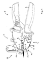
- FIG. 1 shows a perspective view of a crimping apparatus according to FIG Invention with pliers drive.
- a trained in a known manner pliers 1 has an upper Anlagenbakken 2 and a lower working jaw 3, which is about a common axis 4 are pivotable.
- the pivoting of the working jaws 2, 3 is done by Actuation of handles 5, 6, such that upon movement of the handles 5, 6 on the work jaws 2, 3 are pivoted about the axis 4, that closes a pliers mouth 7 formed by them, and vice versa.
- the forceps jaw 7 opens the detailed structure of the pliers 1 itself will not be discussed further here because pliers of this type are well known.
- Each of the working jaws 2, 3 consists of two parallel and spaced apart lying sheets 8, 9 and 10, 11. Between these sheets 8, 9 and 10, 11 is a plate-shaped support frame 12 of a Vercrimpungsaku 13 to lie.
- the crimping unit is 13 via bolts 14, 15 at the upper working jaw 2 and lower working jaws 3 held.
- the bolt 14 comes with its ends in openings the sheets 8, 9 to lie and protrudes, as will be explained is a crimping punch and a hold-down in the support frame 12 are arranged.
- the bolt 15 comes with its ends in openings the sheets 10 and 11 to lie and extends through a through hole in the lower region of the support frame 12.
- the plate-shaped support frame 12 is guided largely free of play and is positioned by this. Be the working jaws 2, 3 on actuation the handles 5, 6 pivoted, the bolts 14, 15 are corresponding moves, resulting in a relative displacement between crimping die and Carrier frame 12 leads and allows a crimping process.
- FIG. 2 shows an enlarged detail of FIG. 1 in the region of FIG Forceps jaw 7 and taken out of the forceps jaw 7 Vercrimpungstechnik 13th
- the crimping unit 13 has the already mentioned plate-shaped support frame 12 on.
- This support frame 12 is preferably made in one piece, made of plastic or metal, and is parallelepiped-like, thus has opposite side walls 16 and 17.
- a circumferential End edge 18 limits the support frame 12 edge.
- the support frame 12 is formed longer as in a horizontal direction 20 shown in Figure 2.
- the horizontal direction 20 parallel to the forceps longitudinal direction, in which so the Handles 5, 6 extend, while the vertical direction 19 perpendicular thereto lies.
- the plate-shaped support frame 12 a guide slot 21 which extends parallel to the vertical direction 19. It extends over the entire thickness of the support frame 12, wherein its corresponding longitudinal side walls parallel to each other and perpendicular to the walls 16, 17 lie. Seen in its longitudinal direction reaches the But guide step 21 never the edge of the support frame 12. Instead it opens in its lower part in a working slot 22, the parallel to the horizontal direction 20 extends and extends to the front end edge 18 of the support frame 12 extends.
- Vercrimpungsaku 13 comes the front end edge 18 of the support frame 12th lie in the front region of the forceps jaw 7.
- the working slot 22 itself is limited by an upper and a lower slot wall 23, the parallel to each other and perpendicular to the walls 16, 17 lie.
- a crimping die 24 In the bottom Slit wall 23 is a crimping die 24. It is the mouth the guide slot 21 opposite.
- the crimping unit 13 held over the bolts 14 and 15 on the working jaws 2 and 3.
- the bolt 14 passes through the through hole 26 and comes in the end Openings 29, 30 of the sheets 8, 9 to lie.
- the bolt 15 further penetrates a through hole 31 below the die 24 and comes at the end in openings 32, 33 of the sheets 10 and 11 to lie.
- bracket 34 To stabilize the support frame 12 on the one hand serves a bracket 34, the above the working slot 22 parallel to this on the side wall 17 with Help of screws 35, 36 is attached to the support frame 12.
- the screws 35, 36 are located on the left and right of the guide slot 21 so that the in Figure 2 left of the guide slot 21 lying portion of the support frame 12 is additionally held by the bracket 34.
- the bracket 34 has it In addition, leadership function for the sliding in the guide slot 21 hold-down 27.
- FIGS. 3 and 4 show the more detailed construction of carrier frame 12. Crimping die 25 and hold-down 27 on the one hand and the more detailed structure the feed unit 39 on the other hand. Same parts as in the figures 1 and 2 are denoted by the same reference numerals and will not be repeated described.
- a dovetail-shaped recess 40 located in the lower slot wall 23rd the carrier frame 12 a dovetail-shaped recess 40, the serves to receive the crimping die 24.
- the crimp die 24 has two mutually parallel, half-inner-like recesses 41, 42, which are best seen in Figure 2 and Figure 6 can be seen.
- This semicircular Holes with a round cross section are transverse to the longitudinal direction the working slot 22 and serve to the crimping die 24 tapered On the one hand, to bend the legs of crimping elements inwards and backwards. This will be done in more detail.
- the construction of the crimping die 25 can best be seen in FIG. outgoing from a rod with rectangular cross-section he is characterized obtained that the rod in its upper region with a recess 43rd is provided for receiving a compression spring 44.
- the recess 43 is located on the side of the rectangular bar, the side wall 17 of the support frame 12 points. Below the recess 43 is in the rectangular Rod the through hole 26, which is parallel to the pliers axis 4 runs. It runs at the same time perpendicular to the side walls 16 and 17. Below the area of the rectangular bar in which the Through hole 26 is located, the rod is at opposite ends Reduced in their thickness so that a central web remains, which forms the actual crimp stamp.
- the structure of the hold-down 27 is also best seen in Figure 4. He is also made of a rod with a rectangular cross-section. In its central region, this rod has a recess 45 which faces the side 16 of the support frame 12, the rod being further away starting from the recess 45 down with a central longitudinal slot 46 is provided. This longitudinal slot extends to the lower Edge of the blank holder and is perpendicular to the side walls 16, 17 of the Support frame 12. Toward the side wall 16, the longitudinal slot 46 is open, while closed in the direction of the side wall 17 of the support frame 12 is. The remaining in the region of the recess 45 side wall the hold-down 27 contains the already mentioned slot 28, which is located in Longitudinal direction of the rectangular rod extends.
- One above the recess 45 lying portion of the blank holder 27 has at its upper End face a recess 47 for receiving the lower end of the Compression spring 44.
- Crimping die 25 and hold-down 27 are set into one another, that the lower web of the crimping die 25 in the longitudinal slot 46 of the blank holder 27 to lie comes.
- the passage opening 26 receiving the central region of the crimping die 25 comes to lie in the recess 45, while the upper thicker portion of the blank holder 27 in the recess 43 of the Crimping stamp 25 comes to rest.
- the compression spring 44 is then supported on the one hand in the recess 47 and on the other hand on an upper roof surface 48 of the crimping die 25. The compression spring 44 thus always tries to Hold-down 27 relative to the crimping die 25 in the direction of the crimping die 24 to introduce.
- the assembled state of crimping dies 25 and Downholder 27 is shown on the right in FIG.
- the contact pressure of the blank holder 27 is here on largest, which acts in front of and behind the recesses 41, 42, and thus one to be processed object practically against the lower slot wall 23rd presses.
- the bolt moves away 14 from the crimping die 24 and first lifts off the crimping die 25, while the hold-down 27 is still working with reduced contact pressure, until finally he is lifted off the object when the bolt 24 against the upper edge of the slot 28 abuts.
- FIG. 3 also shows in its left part a perspective view of FIG Feeding unit 39 for crimping elements.
- the feeding unit 39 is opened Bolt 49, 50 mounted from the side wall 16 of the support frame 12th stand, wherein the feed unit 39 further by means of the screw 36th is pulled against the side wall 16.
- the feed unit 39 is used to belt-shaped interconnected Crimping elements the processing area between crimping die 25 and To feed crimping die 24.
- the crimping elements are shown in FIG. 3 below the supply unit 39 and provided with the reference numeral 51.
- one of the crimping elements 51 consists of a base 52 and two Legs 53, 54 connected to the base 52 at opposite ends are and parallel to each other. Adjacent crimping elements 51 are connected via a connecting portion 55 which is between the respective ones Base regions 52 is located.
- Crimping elements 51 and connecting portion 55 consist of electrically conductive material.
- Crimpstempel 25 and crimping die 24 They become the editing area between Crimpstempel 25 and crimping die 24 fed so that the Leg 53, 54 in the longitudinal direction of the working slot 22 seen one behind the other to come to rest.
- one or more crimping elements 51 be positioned above the die 24 per machining operation if desired.
- the legs 53, 54 of the crimping elements 52 then point to the Crimping die 24 too.
- the leg 53 of the crimping element would 52 come to rest above the recess 41 and the leg 54 of the same crimping element 52 above the recess 42. Is the Crimp element 52 pressed against the crimp die 24, the legs 53, 54 bent back inwards and upwards.
- the belt-shaped interconnected crimping elements 51 come in the Feeding unit 39 to lie on a drainage slope 57. It is about here about a thin plate, the thickness of the inner spacing of the legs 53, 54 of the respective crimping elements 51 corresponds.
- the crimping elements 51 slip practically along the drainage slope 57 in the direction of the crimping die 24.
- the drainage slope 57 forming plate is by means of a screw 58th laterally screwed against a block 59 of the feed unit 39 and extends to the path of the crimping die 25. At the end of the drainage slope 57 is thus an edge 60 is present, which lie above the crimping die 24 comes and a cutting edge for separating from the processing area supplied crimping elements 51 forms.
- the other cutting edge is through the cutting edge 60 facing edge of the crimping die 25 is formed and is provided in Figure 3 by the reference numeral 61.
- the Drain bevel 57 for example, two crimping elements 51 above the crimping die 24 positions and is now the crimping die 25 in the direction of Crimping die 24 moves, so are the belt-shaped contiguous Crimping elements 51 in the connecting portion 55 through the cutting edges 60, 61st separated from each other.
- a guide 62 may be provided, that is a kind of upper guide rail.
- the feed unit 39 can also still with a lower support 63 may be provided which is spaced from its bottom and pulled out to the front, and in support of being processed Good serves.
- Figures 5 to 8 show in more detail the feeding and positioning of the Crimping elements 51 in the processing area between crimping die and hold-down 27 on the one hand and Crimpgesenk 24 on the other.
- the feeding of the crimping elements 51 takes place according to FIG 5 with down pointing legs 53, 54, wherein in each case two of these crimping 51st be arranged simultaneously above the crimping die 24.
- the crimping elements 51 come in the longitudinal direction the recesses 41, 42 next to each other, as with reference to the figure 6 becomes clear (there they are omitted for the sake of clarity).
- the crimping die 25 is still raised in FIG. 6, then first at lowered hold-down 27, the crimping elements 51 within the by positioned the hold-down 27 formed chamber.
- the chamber is going through formed the longitudinal slot 46 in Figure 4.
- the hold-down 27 with its end faces opposite flat areas of the crimping die 24, between which the recesses 41 and 42 are located.
- This Recesses 41, 42 is only the crimping die 25 opposite.
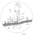
- FIG. 9 shows how using the crimping device according to the invention two FPC conductors 66 and 67 are connected together.
- the respective ones FPC conductors consist of an insulating film 68 with parallel thereto mutually arranged interconnects 69. These interconnects 69 are again with a very thin insulating plastic coating covered, which is not shown. Should two tracks be different FPC conductors 66, 67 are connected together, so are the FPC conductors 66, 67 one above the other in the working area of the crimping device arranged.
- the conductors 69 of the different FPC conductors are thus in Longitudinal direction to each other. However, they are still through the respective insulation isolated against each other.
- FIG. 11 A corresponding cut in this direction C is shown in FIG. 11. It is Here is a cross-sectional view perpendicular to the longitudinal direction superimposed interconnects 69 different FPC conductors 66, 67th As a result of the crimping process, the mandrel 56 penetrates the inside of the Base of the crimping element 51, the upper insulating layer of the conductor 69 of the upper FPC conductor 67, while the inward and backward bent legs 53, 54 penetrate the lower insulation of the lower FPC conductor 66 and contact the conductor 69. This is an electrical contact between the conductive traces 69 of lower and upper FPC conductors 66, 67 conditions.
Abstract
Description
Die Erfindung betrifft eine Crimpvorrichtung gemäß der im Anspruch 1 genannten
Art.The invention relates to a crimping apparatus according to the recited in
Zum allgemein bekannten Stand der Technik gehören bereits Crimpzangen und automatisch betätigbare Crimpvorrichtungen bzw. Crimpautomaten. Sollen mit ihnen unterschiedliche Vercrimpungen ausgeführt werden, so ist es erforderlich, die jeweiligen Crimpstempel und Crimpgesenke auszutauschen. Dies ist relativ umständlich und es besteht die Gefahr, daß nicht zu Crimpstempeln passende Crimpgesenke, und umgekehrt, ausgewählt werden, was die Gefahr von Fehlvercrimpungen mit sich bringt. Zueinander passende Crimpstempel und Crimpgesenke müssen andererseits einjustiert werden, so daß ihr Austausch relativ zeitaufwendig und umständlich ist.Crimping tools already belong to the well-known state of the art and automatically actuatable crimping or crimping machines. Should with them different crimps are executed, so it is necessary to exchange the respective crimping dies and crimp dies. This is relatively cumbersome and there is a risk that not to Crimpstempeln matching crimping dies, and vice versa, be selected what the risk of Fehlvercrimpungen brings with it. Matching On the other hand, the crimping dies and the crimping dies must be adjusted so that their exchange is relatively time consuming and cumbersome.
Aus dem Deutschen Gebrauchsmuster 299 10 927.5 ist bereits ein Werkzeugmodul zum wahlfreien Einsatz in unterschiedliche Werkzeuge, etwa in Zangen oder Automaten, bekannt. Dieses Werkzeugmodul weist einen unteren Modulblock und einen oberen Modulblock auf sowie als Führungssäulen ausgebildete Führungsmittel zur Führung von unterem und oberem Modulblock relativ zueinander. Die Modulblöcke sind mit Antriebsmitteln koppelbar, wobei die Modulblöcke auch dazu verwendet werden können, Vercrimpungen auszuführen. In diesem Fall sind sie mit entsprechenden Stempeln bzw. Gesenken zu versehen. Ein Austausch dieser Stempel bzw. Gesenke zur Durchführung anderer Vercrimpungsarbeiten kann dann in einfacher Weise dadurch geschehen, daß das gesamte Werkzeugmodul durch ein anderes ersetzt wird. Somit ist gewährleistet, daß immer zueinander passende Crimpstempel und Crimpgesenke verwendet werden und eine Neujustierung der Elemente nicht erforderlich ist. Mehrere Werkzeugmodule dieser Art können am Montageort bereitgestellt sein, so daß ein Monteur je nach Art der durchzuführen Arbeiten das gerade Geeignete auswählen kann.From the German Utility Model 299 10 927.5 is already a tool module For optional use in different tools, such as pliers or vending machines, known. This tool module has a lower module block and an upper module block formed as well as guide columns Guide means for guiding the lower and upper module block relative to each other. The module blocks can be coupled to drive means, wherein The module blocks can also be used to perform crimping. In this case they are with appropriate punches or dies to provide. An exchange of these punches or dies for implementation other crimping can then easily be done by that the entire tool module is replaced by another one. Consequently ensures that always matching crimping dies and crimp dies can be used and a readjustment of the elements is not required is. Several tool modules of this type can be provided at the installation site so that a fitter can perform according to the type of work that can choose just right.
Nachteilig bei den bekannten Werkzeugmodulen ist allerdings, daß sie relativ schwer und unhandlich und darüber hinaus kompliziert im Aufbau sind. Sollen darüber hinaus mit ihnen auf Folien befindliche Leiterbahnen durch Vercrimpung miteinander verbunden werden, so lassen sich diese nach der Verbindung und bei zu großer Gesamtlänge nur noch umständlich aus dem Bereich zwischen Crimpstempel und Crimpgesenk herausführen, da sie hieran durch die Führungssäulen gehindert werden.A disadvantage of the known tool modules, however, is that they are relative heavy and unwieldy and, moreover, are complicated in construction. Should in addition with them on slides located tracks by crimping be connected with each other, so these can be after the connection and if the overall length is too long it is only cumbersome lead out between crimping die and crimping die, as they are there be prevented by the guide columns.
Aus der US 3,710,610 die als nächstliegender Stand der Technik angesehen wird ist eine Crimpvorrichtung bekannt, die einen plattenförmigen Trägerrahmen aufweist, in dem ein Führungsschlitz zur Aufnahme eines Crimpstempels vorgesehen ist. Ein Crimpgesenk ist an einem Ende des Führungsschlitzes so gehalten, dass das Crimpgesenk dem Crimpstempel gegenüber liegt. Am Trägerrahmen und am Crimpstempel sind Mitnahmemittel vorgesehen, so dass der Crimpstempel auf das Crimpgesenk zu bzw. von diesem weg bewegbar ist.From US 3,710,610 as the closest prior art is considered a crimping device is known, which is a plate-shaped Carrier frame, in which a guide slot for receiving a crimping punch is provided. A crimping die is at one end of the Guide slot held so that the crimping die opposite the crimping die lies. On the support frame and the crimping die are takeaway provided so that the crimping die on the Crimpgesenk to or from this away is movable.
Der Trägerrahmen weist eine Unterbrechung auf, die Platz lässt, um Kontaktösen dem Crimpbereich zuführen zu können, die an einem Streifen gehalten sind, der mittels einer Führungseinrichtung geführt ist, die eine Halteplatte aufweist, mit der die Unterbrechung auf der Seite abgedeckt ist, von der ein Leiter mit seinem Ende voraus in den Crimpbereich einführbar ist. Nach dem Vercrimpen einer Kontaktöse mit einem Leiterende, bei dem zunächst die Öse vom Band getrennt und dann mit dem Leiter und der Isolation vercrimpt wird, kann dann das fertig bearbeitete Leiterende entgegen seiner Einführrichtung aus der Crimpeinrichtung entnommen werden.The support frame has an interruption that leaves room for eyelets to be able to supply the crimping area, which is held on a strip are, which is guided by means of a guide device, which is a holding plate having the interruption on the page covered by the one Head with its end in advance in the crimping is insertable. After this Crimping a contact eye with a conductor end, at first the eyelet separated from the belt and then crimped with the conductor and the insulation is, then the finished end of the conductor against its insertion direction are removed from the crimping device.
Eine derartige Crimpvorrichtung eignet sich zwar, um Kontaktelemente an Leiterenden anzubringen, für die Verbindung von Leitern, insbesondere für die Verbindung von Leiterbahnen, die sich auf flächigen Folien befinden, ist sie jedoch völlig ungeeignet.Although such a crimping device is suitable for contact elements To attach conductor ends, for the connection of conductors, in particular for the connection of printed conductors, which are located on sheet-like films, is but completely unsuitable.
Der Erfindung liegt die Aufgabe zugrunde, eine weitere Crimpvorrichtung zu schaffen, die nicht nur einen einfachen Aufbau aufweist, einen schnellen Austausch von Crimpstempel und Crimpgesenk gestattet, sondern die sich auch besser zur Verbindung von Leitern, insbesondere von auf Folien oder dergleichen befindlichen Leiterbahnen durch Vercrimpung miteinander eignet.The invention has the object of providing a further crimping device create, which not only has a simple structure, a fast Exchange of crimping dies and crimping dies is allowed, but the themselves Also better for connecting conductors, especially on films or Like located interconnects by crimping each other is suitable.
Die Lösung der gestellten Aufgabe ist im Anspruch 1 angegeben. Vorteilhafte
Ausgestaltungen der Erfindung sind den Unteransprüchen zu entnehmen. The solution of the problem is specified in
Eine erfindungsgemäße Crimpvorrichtung enthält wenigstens: einen plattenförmigen Trägerrahmen; einen im Trägerrahmen vorhandenen Führungsschlitz zur Aufnahme eines Crimpstempels; einen quer zum Führungsschlitz verlaufenden Arbeitsschlitz, in den der Führungsschlitz mündet, wobei sich der Arbeitsschlitz bis zu einer Stirnkante des Trägerrahmens erstreckt; ein Crimpgesenk in einer Schlitzwand des Arbeitsschlitzes; und jeweils am Trägerrahmen sowie am Crimpstempel vorhandene Mitnahmemittel, über die der Crimpstempel auf das Crimpgesenk zu- bzw. von diesem wegbewegbar ist.A crimping device according to the invention contains at least: a plate-shaped Support frame; an existing in the support frame guide slot for receiving a crimping punch; one across the guide slot extending working slot into which the guide slot opens, wherein the working slot extends to an end edge of the support frame; one Crimpgesenk in a slot wall of the working slot; and each on the support frame as well as the crimping stamp existing driving means, over which the Crimping stamp on the crimping die to or can be moved away from this.
Die Crimpvorrichtung nach der Erfindung kann um eine Zange oder einen Crimpautomaten zum Antrieb von Trägerrahmen und Crimpstempel ergänzt sein. Zum Beispiel kann sie eine Zange mit zwei Arbeitsbacken aufweisen, von denen jeweils einer über die jeweiligen Mitnahmemittel den Trägerrahmen bzw. den Crimpstempel mitnimmt. Ein Austausch von Crimpstempel und Crimpgesenk ist dann in einfacher Weise durch Austausch der den Trägerrahmen, den Crimpstempel und das Crimpgesenk enthaltenden Baueinheit möglich. Entsprechendes gilt bei einem Crimpautomaten. Die Baueinheit weist darüber hinaus einen einfachen Aufbau auf, da der vorzugsweise einstückig ausgebildete Trägerrahmen lediglich als bewegbares Teil den Crimpstempel aufzunehmen hat. Führungssäulen zur Führung oberer und unterer Modulblöcke, die ihrerseits Crimpstempel und Crimpgesenk aufnehmen, sind dabei nicht mehr erforderlich, so daß auch ein besserer Zugang zum Bereich zwischen Crimpstempel und Crimpgesenk möglich ist. Miteinander durch Vercrimpung verbundene Leiter können somit wieder leichter aus dem Bereich zwischen Crimpstempel und Crimpgesenk herausgenommen werden, was insbesondere vorteilhaft ist, wenn deren Gesamtlänge nach Vercrimpung relativ groß ist.The crimping device according to the invention may be around a pair of pliers or a Crimping machines for driving carrier frames and crimping dies added be. For example, it may have pliers with two working jaws, one of which in each case via the respective driving means the support frame or takes the crimp stamp. An exchange of crimping dies and Crimping die is then in a simple manner by replacing the support frame, the crimping die and the crimp die containing assembly possible. The same applies to a crimping machine. The construction unit Moreover, it has a simple structure, as it is preferably in one piece trained support frame only as a movable part of the crimping die has to absorb. Guide columns for guiding upper and lower Module blocks which in turn receive crimping dies and crimp dies are no longer necessary, so that also a better access to the area between crimping die and crimp die is possible. Through each other Crimping connected conductors can thus become easier again from the field between the crimping die and the crimping die, which is particularly advantageous if their total length after crimping is relatively large.
So können mit Hilfe der erfindungsgemäßen Crimpvorrichtung zum Beispiel sogenannte FPC- (flat printed circuit) Leiter miteinander verbunden werden. Bei ihnen handelt es sich um auf isolierende Folien aufgebrachte elektrische Leiterbahnen, etwa aus Kupfer. Um zwei solche FPC-Leiter miteinander zu verbinden, werden diese übereinander gelegt und von einem speziell ausgebildeten und noch zu beschreibenden Crimpelement, das an sich bekannt ist, durchdrungen und damit kontaktiert. Da der Bereich zwischen Crimpstempel und Crimpgesenk von drei Seiten her zugänglich ist, können somit auch FPC-Leiter, die auf relativ großflächigen Folien zu liegen kommen, bearbeitet werden.For example, with the aid of the crimping device according to the invention so-called FPC (flat printed circuit) conductors are interconnected. They are applied to insulating films electrical Tracks, such as copper. To connect two such FPC conductors together These are superimposed and made by a specially trained and to be described crimping element, which is known per se penetrated and contacted. As the area between crimping dies and Crimpgesenk is accessible from three sides, thus also FPC conductors, which come to rest on relatively large sheets are processed.
Nach einer Ausgestaltung der Erfindung sind die Mitnahmemittel Öffnungen zur Aufnahme von Achsstücken, und dergleichen, oder sie sind als Ansätze ausgebildet, so daß über diese Achsstücke bzw. Ansätze Antriebsmittel, etwa Arbeitsbacken einer Zange, auf den Trägerrahmen bzw. den Crimpstempel wirken können.According to one embodiment of the invention, the entrainment means are openings for receiving axle pieces, and the like, or they are as lugs designed so that about these axles or lugs drive means, such as Working jaws of a pair of pliers, on the support frame or the crimping die can act.
Nach einer sehr vorteilhaften Weiterbildung der Erfindung trägt der Crimpstempel einen seitlich zu ihm liegenden Niederhalter, der einen im Bereich zwischen Crimpstempel und Crimpgesenk befindlichen Gegenstand dadurch fixiert, daß er diesen gegen diejenige Schlitzwand des Arbeitsschlitzes drückt, in der sich das Crimpgesenk befindet. Der Gegenstand kann zum Beispiel durch zwei aufeinanderliegende FPC-Leiter gebildet sein. Die entsprechenden Folien werden dann vor und während des Vercrimpungsvorgangs durch den Niederhalter fixiert, so daß sich die Relativposition der zu vercrimpenden Teile während des Vercrimpungsvorgangs nicht mehr ändern kann. Auf diese Weise werden saubere Crimpergebnisse bzw. Leiterverbindungen erzielt.After a very advantageous development of the invention carries the crimping die a down to him lying down, the one in the area between the crimping die and the crimping die fixed that he presses against the slit wall of the working slot, in which the crimping die is located. The item can be, for example be formed by two superimposed FPC conductor. The corresponding Foils are then passed through before and during the crimping process Hold down fixed, so that the relative position of the parts to be crimped can not change during the crimping process. To this This way, clean crimping results or conductor connections are achieved.
Nach einer weiteren vorteilhaften Ausgestaltung der Erfindung liegt der Niederhalter in Längsrichtung des Arbeitsschlitzes gesehen an beiden Seiten des vorzugsweise als Rechtecksäule ausgebildeten Crimpstempels an. Der Niederhalter befindet sich ebenfalls im Führungsschlitz des Crimpstempels, wobei zwischen Crimpstempel und Niederhalter eine Federeinrichtung wirkt, die versucht, die zum Crimpgesenk weisende Stirnkante des Niederhalters gegenüber der entsprechenden Stirnkante des Crimpstempels vorzustellen, derart, daß diese Stirnkante des Niederhalters die Stirnkante des Crimpstempels überragt. Oberhalb des Crimpgesenks wird dabei durch Crimpstempel und Niederhalter eine Kammer gebildet, in die seitlich ein Crimpelement einführbar ist, das dann durch den Crimpstempel in Richtung Crimpgesenk gedrückt wird. Das Crimpelement wird also innerhalb der Kammer positioniert und geführt, wenn es in Richtung Crimpgesenk bewegt wird, was zu einer verbesserten Crimpqualität führt.According to a further advantageous embodiment of the invention, the hold-down is seen in the longitudinal direction of the working slot on both sides of the preferably designed as a rectangular column Crimpstempels. The hold down is also in the guide slot of the crimping die, wherein between Crimpstempel and hold down a spring device acts, the tries to face the edge of the hold-down facing the crimping die the corresponding end edge of the crimping die, thus, that this end edge of the blank holder, the front edge of the crimping die surmounted. Above the crimping die is by crimping dies and Hold-down a chamber formed in the side of a crimp insertable is, then pressed by the crimping punch in the direction of Crimpgesenk becomes. The crimping element is thus positioned and guided inside the chamber, when it is moved towards the crimping die, resulting in an improved Crimp quality leads.
In Ausgestaltung der Erfindung weist der Niederhalter ein in Längsrichtung des Führungsschlitzes verlaufendes Langloch auf, das ein Achsstück oder einen Ansatz des Crimpstempels aufnimmt. Dadurch läßt sich die Bewegung des Niederhalters relativ zum Crimpstempel in Längsrichtung des Führungsschlitzes in einfacher Weise steuern. Wird der Crimpstempel vom Crimpgesenk wegbewegt, nimmt er nach einer gewissen Zeit den Niederhalter mit, wenn das Achsstück bzw. der Ansatz gegen die das Langloch in dieser Richtung begrenzende Wand des Niederhalters läuft.In an embodiment of the invention, the hold-down device has a longitudinal direction the guide slot extending slot on which an axle or a Approach of Crimpstempels absorbs. This allows the movement the hold-down relative to the crimping die in the longitudinal direction of the guide slot control in a simple way. Will the crimp die from the crimp die moved away, he takes the hold-down after a certain time, if the axle piece or the approach against the slot in this direction Restraining wall of holddown is running.
Der Trägerrahmen nach der Erfindung trägt vorteilhaft eine Zuführungseinheit zum Zuführen von Crimpelementen zum Crimpgesenk, um eine einfachere und fehlerfreiere Zuführung der Crimpelemente zu gewährleisten. Beispielswiese kann die Zuführungseinheit Π-förmige Crimpelemente mit einer Basis und zwei dazu parallelen Schenkeln in einer Richtung transportieren, die senkrecht zu der von Basis und Schenkeln aufgespannten Ebene liegt. Dabei kommen die Schenkel so zu liegen, daß diese in Richtung des Crimpgesenks weisen und in Längsrichtung des Arbeitsschlitzes gesehen hintereinander liegen. Sobald sie in die durch den Niederhalter und den Crimpstempel gebildete Kammer eingeführt worden sind, können sie durch den Crimpstempel weiter mit ihren freien Schenkelenden voran in Richtung Crimpgesenk bewegt werden. Befinden sich jetzt aufeinanderliegende FPC-Leiter unterhalb des Crimpstempels, so werden diese von den freien Enden der Schenkel der Crimpelemente durchdrungen, die anschließend durch das Crimpgesenk nach innen und zurück gebogen werden, so daß auf diese Weise eine elektrisch einwandfreie Verbindung zwischen den FPC-Leitern zustande kommt. Nach innen weisende Ansätze im Bereich der Basis der Crimpelemente können zur Verbesserung des elektrischen Kontaktes dienen. The support frame according to the invention advantageously carries a feed unit for feeding crimping elements to the crimp die, a simpler one and to ensure error-free feeding of the crimping elements. example meadow can the feed unit Π-shaped crimping with a Transport base and two parallel legs in one direction, which lies perpendicular to the plane spanned by the base and legs. The legs come to rest so that these in the direction of the crimping die wise and seen in the longitudinal direction of the working slot one behind the other lie. Once they are in through the hold down and the crimping punch formed chamber, they can through the crimping punch moved further with their free leg ends in the direction of the crimping die become. Are now superimposed FPC conductors below of the crimping die, these are from the free ends of the legs of the Penetrated crimping elements, which subsequently by the crimping die after be bent inside and back, so that in this way an electric perfect connection between the FPC conductors is achieved. To internal approaches in the area of the base of the crimping elements can be used for Serve to improve the electrical contact.
Der Niederhalter kann den Crimpstempel vorzugsweise an drei Seiten umgeben und somit im Bereich der Kammer einen in Zuführrichtung der Crimpelemente liegenden Anschlag bilden, um dem Trägerrahmen zugeführte Crimpelemente relativ zum Crimpgesenk zu positionieren. Dabei kann der Anschlag so ausgebildet sein, daß gegen ihn nur die Schenkel der Crimpelemente führbar sind. Werden über ihre Basis bandförmig miteinander verbundene Crimpelemente dem Trägerrahmen zugeführt und in ihrem Verbindungsbereich von den restlichen Crimpelementen abgeschnitten, hängt die Positionierung der im Trägerrahmen befindlichen Crimpelemente nicht mehr von der Position des Schnittes ab, so daß es nicht zu Fehlpositionierungen der Crimpelemente innerhalb des Trägerrahmens kommen kann.The hold-down may preferably surround the crimping punch on three sides and thus in the region of the chamber one in the feed direction of the crimping elements form lying stop to the carrier frame supplied To position crimping elements relative to the crimping die. It can the Stop be designed so that against him only the legs of the crimping elements are feasible. Be banded together over their base Crimping elements fed to the support frame and in their connection area Cut off from the remaining crimping elements, the positioning depends the crimping elements located in the support frame no longer from the Position of the cut so that it does not lead to incorrect positioning of the crimping elements can come within the support framework.
Vorzugsweise weist die Zuführungseinheit eine Unterstützungsfläche für die Crimpelemente auf, die bis an die Bahn des Crimpstempels reicht, wobei die einander zugewandten Kanten von Crimpstempel und Unterstützungsfläche eine Schneideinrichtung bilden. Durch sie lassen sich in einfacher Weise bereits in die Kammer eingeführte Crimpelemente von den restlichen und bandförmig miteinander verbundenen Crimpelementen abtrennen.Preferably, the feed unit has a support surface for the Crimping elements, which extends to the path of the crimping die, wherein the facing edges of crimping die and support surface form a cutting device. Through them can be easily already introduced into the chamber crimping elements of the remaining and band-shaped Separate interconnected crimping elements.
Ein Ausführungsbeispiel der Erfindung wird nachfolgend unter Bezugnahme
auf die Zeichnung näher beschrieben. Es zeigen:
Die Figur 1 zeigt in perspektivischer Ansicht eine Crimpvorrichtung nach der Erfindung mit Zangenantrieb.FIG. 1 shows a perspective view of a crimping apparatus according to FIG Invention with pliers drive.
Eine in bekannter Weise ausgebildete Zange 1 weist einen oberen Arbeitsbakken
2 und einen unteren Arbeitsbacken 3 auf, die um eine gemeinsame Achse
4 schwenkbar sind. Die Verschwenkung der Arbeitsbacken 2, 3 erfolgt durch
Betätigung von Handgriffen 5, 6, derart, daß bei Bewegung der Handgriffe 5,
6 aufeinander zu die Arbeitsbacken 2, 3 so um die Achse 4 verschwenkt werden,
daß sich ein durch sie gebildetes Zangenmaul 7 schließt, und umgekehrt.
Bei Entlastung der Handgriffe 5, 6 öffnet sich das Zangenmaul 7. Auf
den detaillierten Aufbau der Zange 1 selbst soll hier nicht weiter eingegangen
werden, da Zangen dieser Art allgemein bekannt sind.A trained in a known
Jeder der Arbeitsbacken 2, 3 besteht aus zwei parallel und im Abstand zueinander
liegenden Blechen 8, 9 bzw. 10, 11. Zwischen diesen Blechen 8, 9 bzw.
10, 11 kommt ein plattenförmiger Trägerrahmen 12 einer Vercrimpungseinheit
13 zu liegen. Wie noch genauer beschreiben wird, ist die Vercrimpungseinheit
13 über Bolzen 14, 15 am oberen Arbeitsbacken 2 bzw. unteren Arbeitsbacken
3 gehalten. Der Bolzen 14 kommt dabei mit seinen Enden in Öffnungen
der Bleche 8, 9 zu liegen und durchragt, wie noch ausgeführt werden
wird, einen Crimpstempel und einen Niederhalter, die im Trägerrahmen 12
angeordnet sind. Dagegen kommt der Bolzen 15 mit seinen Enden in Öffnungen
der Bleche 10 und 11 zu liegen und durchragt eine Durchgangsöffnung
im unteren Bereich des Trägerrahmens 12. Zwischen den Blechen 8, 9 bzw.
10, 11 ist der plattenförmige Trägerrahmen 12 weitestgehend spielfrei geführt
und wird durch diese positioniert. Werden die Arbeitsbacken 2, 3 bei Betätigung
der Handgriffe 5, 6 verschwenkt, werden die Bolzen 14, 15 entsprechend
bewegt, was zu einer Relativverschiebung zwischen Crimpstempel und
Trägerrahmen 12 führt und einen Crimpvorgang ermöglicht.Each of the working
Die Figur 2 zeigt einen vergrößerten Ausschnitt aus Figur 1 im Bereich des Zangenmauls 7 und bei aus dem Zangenmaul 7 herausgenommener Vercrimpungseinheit 13. FIG. 2 shows an enlarged detail of FIG. 1 in the region of FIG Forceps jaw 7 and taken out of the forceps jaw 7 Vercrimpungseinheit 13th
Die Vercrimpungseinheit 13 weist den bereits erwähnten plattenförmigen Trägerrahmen
12 auf. Dieser Trägerrahmen 12 ist vorzugsweise einstückig hergestellt,
etwa aus Kunststoff oder Metall, und ist parallelplattenartig ausgebildet,
weist also gegenüberliegende Seitenwände 16 und 17 auf. Eine umlaufende
Stirnkante 18 begrenzt den Trägerrahmen 12 randseitig. In einer in Figur
2 gezeigten Vertikalrichtung 19 ist der Trägerrahmen 12 länger ausgebildet
als in einer in Figur 2 gezeigten Horizontalrichtung 20. Dabei liegt die Horizontalrichtung
20 parallel zur Zangenlängsrichtung, in der sich also die
Handgriffe 5, 6 erstrecken, während die Vertikalrichtung 19 senkrecht dazu
liegt.The crimping
Wie die Figur 2 weiter erkennen läßt, weist der plattenförmige Trägerrahmen
12 einen Führungsschlitz 21 auf, der parallel zur Vertikalrichtung 19 verläuft.
Er erstreckt sich über die gesamte Dicke des Trägerrahmens 12, wobei
seine entsprechenden Längsseitenwände parallel zueinander und senkrecht
zu den Wänden 16, 17 liegen. In seiner Längsrichtung gesehen erreicht der
Führungsschritt 21 aber niemals den Rand des Trägerrahmens 12. Statt dessen
mündet er in seinem unteren Bereich in einen Arbeitsschlitz 22, der parallel
zur Horizontalrichtung 20 verläuft und sich bis zur vorderen Stirnkante
18 des Trägerrahmens 12 erstreckt. Bei ins Zangenmaul 7 eingesetzter Vercrimpungseinheit
13 kommt die vordere Stirnkante 18 des Trägerrahmens 12
im vorderen Bereich des Zangenmauls 7 zu liegen. Der Arbeitsschlitz 22
selbst wird durch eine obere und eine untere Schlitzwand 23 begrenzt, die
parallel zueinander und senkrecht zu den Wänden 16, 17 liegen. In der unteren
Schlitzwand 23 befindet sich ein Crimpgesenk 24. Es liegt der Mündung
des Führungsschlitzes 21 gegenüber. Innerhalb des Führungsschlitzes 21 befinden
sich ein noch zu beschreibender Crimpstempel 25 mit Durchgangsöffnung
26 sowie ein noch zu beschreibender Niederhalter 27 mit Langloch 28.
Crimpstempel 25 und Niederhalter 27 fluchten dabei mit den Wänden 16 und
17.As the figure 2 can be seen further, the plate-shaped support frame
12 a
Wie bereits anhand der Figur 1 erläutert, wird die Vercrimpungseinheit 13
über die Bolzen 14 und 15 an den Arbeitsbacken 2 und 3 gehalten. Der Bolzen
14 durchläuft dabei die Durchgangsöffnung 26 und kommt endseitig in
Öffnungen 29, 30 der Bleche 8, 9 zu liegen. Der Bolzen 15 durchsetzt ferner
eine Durchgangsöffnung 31 unterhalb des Gesenks 24 und kommt endseitig
in Öffnungen 32, 33 der Bleche 10 und 11 zu liegen. As already explained with reference to FIG. 1, the crimping
Zur Stabilisierung des Trägerrahmens 12 dient einerseits ein Bügel 34, der
oberhalb des Arbeitsschlitzes 22 parallel zu diesem an der Seitenwand 17 mit
Hilfe von Schrauben 35, 36 am Trägerrahmen 12 befestigt ist. Die Schrauben
35, 36 befinden sich links und rechts vom Führungsschlitz 21, so daß der in
Figur 2 links vom Führungsschlitz 21 liegende Abschnitt des Trägerrahmens
12 durch den Bügel 34 zusätzlich gehalten wird. Der Bügel 34 hat darüber
hinaus Führungsfunktion für den im Führungsschlitz 21 verschiebbaren Niederhalter
27. Andererseits trägt der Trägerrahmen 12 in seinem oberen Endbereich
Begrenzungsplatten 37, 38, die mit Hilfe von Schrauben gegen die
Seitenwände 16 und 17 geschraubt sind. Diese Begrenzungsplatten 37, 38
überdecken den oberen Bereich des Führungsschlitzes 21 und haben somit
auch Führungsfunktion für den Crimpstempel 25 einerseits und den Niederhalter
27 andererseits, die bis in diesen oberen Bereich hineingeführt sind.To stabilize the
Nicht zuletzt ist mit dem Trägerrahmen 12 noch eine Zuführungseinheit 39
für Crimpelemente verbunden, und zwar an der Seitenwand 16. Diese Zuführungseinheit
39 wird später genauer beschrieben.Last but not least is a
Die Figuren 3 und 4 zeigen den detaillierteren Aufbau von Trägerrahmen 12.
Crimpstempel 25 und Niederhalter 27 einerseits sowie den genaueren Aufbau
der Zuführungseinheit 39 andererseits. Gleiche Teile wie in den Figuren 1
und 2 sind mit den gleichen Bezugszeichen versehen und werden nicht nochmals
beschrieben.FIGS. 3 and 4 show the more detailed construction of
Wie in Figur 3 zu erkennen ist, befindet sich in der unteren Schlitzwand 23
des Trägerrahmens 12 eine schwalbenschwanzförmige Ausnehmung 40, die
zur Aufnahme des Crimpgesenks 24 dient. Das Crimpgesenk 24 weist zwei
parallel zueinander verlaufende, halbrinnenartige Vertiefungen 41, 42 auf,
die am besten in Figur 2 bzw. Figur 6 zu erkennen sind. Diese halbrinnenartigen
Vertiefungen mit rundem Querschnitt verlaufen quer zur Längsrichtung
des Arbeitsschlitzes 22 und dienen dazu, auf das Crimpgesenk 24 zulaufende
Schenkel von Crimpelementen einerseits nach innen und zurück zu verbiegen.
Dies wird noch genauer ausgeführt werden.As can be seen in Figure 3, located in the lower slot wall 23rd
the carrier frame 12 a dovetail-shaped
Zu erkennen ist in Figur 3 und 4 auch der Aufbau von Crimpstempel 25 und
Niederhalter 27. Sie bilden in zusammengesetztem Zustand eine quasi stangenförmige
Einheit mit rechteckförmigem Querschnitt, die in den Führungsschlitz
21 paßt und nicht über dessen Längsseiten hinaus steht, so daß die
stangenförmige Einheit durch die Begrenzungsplatten 37, 38 einerseits und
den Bügel 34 andererseits bzw. zusätzlich durch die Zuführungseinheit 39
geführt wird. Diese Elemente verhindern ein seitliches Herausfallen von
Crimpstempel 25 und Niederhalter 27 aus dem Führungsschlitz 21.It can be seen in Figure 3 and 4, the construction of crimping dies 25 and
Hold-
Der Aufbau des Crimpstempels 25 ist am besten in Figur 4 zu erkennen. Ausgehend
von einer Stange mit rechteckförmigem Querschnitt wird er dadurch
erhalten, daß die Stange in ihrem oberen Bereich mit einer Ausnehmung 43
zur Aufnahme einer Druckfeder 44 versehen wird. Die Ausnehmung 43 befindet
sich an der Seite der Rechteckstange, die zur Seitenwand 17 des Trägerrahmens
12 weist. Unterhalb der Ausnehmung 43 befindet sich in der rechteckförmigen
Stange die Durchgangsöffnung 26, die parallel zur Zangenachse
4 verläuft. Sie verläuft gleichzeitig senkrecht zu den Seitenwänden 16 und
17. Unterhalb des Bereichs der rechteckförmigen Stange, in welchem sich die
Durchgangsöffnung 26 befindet, ist die Stange an einander gegenüberliegenden
Flächen in ihrer Dicke verringert, so daß ein mittig liegender Steg verbleibt,
der den eigentlichen Crimpstempel bildet. Die zu diesem Zweck abgetragenen
Bereiche der rechteckförmigen Stange liegen in Längsrichtung des
Arbeitsschlitzes 22 gesehen hintereinander. Dieser Steg ist quasi plattenförmig,
wobei die Plattenebene senkrecht zu den Seitenwänden 16, 17 des Trägerrahmens
12 steht. Die freie Stirnfläche dieses Stegs weist auf das Crimpgesenk
24 zu und erstreckt sich mit ihrer Längsrichtung in Längsrichtung
der Vertiefungen 41, 42.The construction of the crimping
Der Aufbau des Niederhalters 27 ist ebenfalls am besten in Figur 4 zu erkennen.
Er ist auch aus einer Stange mit rechteckförmigem Querschnitt hergestellt.
In ihrem mittleren Bereich weist diese Stange eine Ausnehmung 45
auf, die zur Seite 16 des Trägerrahmens 12 weist, wobei die Stange ferner
ausgehend von der Ausnehmung 45 nach unten mit einem zentralen Längsschlitz
46 versehen ist. Dieser Längsschlitz erstreckt sich bis zur unteren
Kante des Niederhalters und steht senkrecht zu den Seitenwänden 16, 17 des
Trägerrahmens 12. In Richtung zur Seitenwand 16 ist der Längsschlitz 46 offen,
während er in Richtung zur Seitenwand 17 des Trägerrahmens 12 geschlossen
ist. Die im Bereich der Ausnehmung 45 verbleibende Seitenwand
des Niederhalters 27 enthält das bereits erwähnte Langloch 28, das sich in
Längsrichtung der rechteckförmigen Stange erstreckt. Ein oberhalb der Ausnehmung
45 liegender Abschnitt des Niederhalters 27 besitzt an seiner oberen
Stirnfläche eine Ausnehmung 47 zur Aufnahme des unteren Endes der
Druckfeder 44.The structure of the hold-down 27 is also best seen in Figure 4.
He is also made of a rod with a rectangular cross-section.
In its central region, this rod has a
Crimpstempel 25 und Niederhalter 27 werden so ineinander gesetzt, daß der
untere Steg des Crimpstempels 25 im Längsschlitz 46 des Niederhalters 27 zu
liegen kommt. Der die Durchgangsöffnung 26 aufnehmende mittlere Bereich
des Crimpstempels 25 kommt in der Ausnehmung 45 zu liegen, während der
obere dickere Abschnitt des Niederhalters 27 in der Ausnehmung 43 des
Crimpstempels 25 zu liegen kommt. Die Druckfeder 44 stützt sich dann einerseits
in der Ausnehmung 47 ab und andererseits an einer oberen Dachfläche
48 des Crimpstempels 25. Die Druckfeder 44 versucht also stets, den
Niederhalter 27 relativ zum Crimpstempel 25 in Richtung des Crimpgesenks
24 vorzustellen. Der zusammengesetzte Zustand von Crimpstempel 25 und
Niederhalter 27 ist in Figur 3 rechts gezeigt. Hier ist der angepreßte Zustand
dargestellt, bei welchem ein Crimpvorgang erfolgt und die Druckfeder 44 am
stärksten komprimiert ist. Die Anpreßkraft des Niederhalters 27 ist hier am
größten, der vor und hinter den Vertiefungen 41, 42 wirkt, und somit einen
zu bearbeitenden Gegenstand praktisch gegen die untere Schlitzwand 23
preßt. Bei Entlastung der Handgriffe 5, 6 der Zange 1 entfernt sich der Bolzen
14 vom Crimpgesenk 24 und hebt zunächst den Crimpstempel 25 ab,
während der Niederhalter 27 noch mit verringerter Anpreßkraft weiter wirkt,
bis er schließlich auch vom Gegenstand abgehoben wird, wenn der Bolzen 24
gegen die obere Kante des Langlochs 28 stößt. Im umgekehrten Fall, also bei
Betätigung der Handgriffe 5, 6 wird zuerst der Niederhalter 27 gegen den zu
bearbeitenden Gegenstand gefahren, und zwar aufgrund der Wirkung der
Druckfeder 44, wobei er mit weiterer Bewegung des Bolzens 14 in Richtung
zum Crimpgesenk 24 stärker gegen den Gegenstand gepreßt wird, bis schließlich
der Crimpstempel 25 den Crimpvorgang beginnt.Crimping
Die Figur 3 zeigt in ihrem linken Teil auch eine perspektivische Ansicht der
Zuführungseinheit 39 für Crimpelemente. Die Zuführungseinheit 39 wird auf
Bolzen 49, 50 aufgesetzt, die von der Seitenwand 16 des Trägerrahmens 12
abstehen, wobei die Zuführungseinheit 39 ferner mit Hilfe der Schraube 36
gegen die Seitenwand 16 gezogen wird. FIG. 3 also shows in its left part a perspective view of
Die Zuführungseinheit 39 dient dazu, gurtförmig miteinander verbundene
Crimpelemente dem Bearbeitungsbereich zwischen Crimpstempel 25 und
Crimpgesenk 24 zuzuführen. Die Crimpelemente sind in Figur 3 unterhalb
der Zuführungseinheit 39 gezeigt und mit dem Bezugszeichen 51 versehen.
Jeweils eines der Crimpelemente 51 besteht aus einer Basis 52 und zwei
Schenkeln 53, 54, die an gegenüberliegenden Enden mit der Basis 52 verbunden
sind und parallel zueinander stehen. Benachbarte Crimpelemente 51
sind über einen Verbindungsbereich 55 verbunden, der zwischen den jeweiligen
Basisbereichen 52 liegt. Crimpelemente 51 und Verbindungsbereich 55
bestehen aus elektrisch leitendem Material. Sie werden dem Bearbeitungsbereich
zwischen Crimpstempel 25 und Crimpgesenk 24 so zugeführt, daß die
Schenkel 53, 54 in Längsrichtung des Arbeitsschlitzes 22 gesehen hintereinander
zu liegen kommen. Dabei können ein oder mehrere Crimpelemente 51
pro Bearbeitungsvorgang oberhalb des Gesenks 24 positioniert werden, falls
gewünscht. Die Schenkel 53, 54 der Crimpelemente 52 weisen dann auf das
Crimpgesenk 24 zu. Im Falle der Figur 3 würde der Schenkel 53 des Crimpelements
52 oberhalb der Vertiefung 41 zu liegen kommen und der Schenkel
54 desselben Crimpelements 52 oberhalb der Vertiefung 42. Wird das
Crimpelement 52 gegen das Crimpgesenk 24 gepreßt, werden die Schenkel
53, 54 nach innen sowie nach oben zurückgebogen. Im Falle von übereinanderliegenden
und miteinander zu verbindenden Leiterbahnen würden dann
die nach oben umgebogenen Schenkel 53, 54 von unter die untere Leiterbahn
kontaktieren, während die obere Leiterbahn dadurch kontaktiert wird, daß an
der Innenseite einer jeweiligen Basis 52 ein nach innen weisender Dorn 56 in
die obere Leiterbahn getrieben wird. Dadurch kommt eine elektrische Verbindung
zwischen den Leiterbahnen zustande, wie noch genauer beschrieben
wird.The
Die gurtförmig miteinander verbundenen Crimpelemente 51 kommen in der
Zuführungseinheit 39 auf einer Ablaufschräge 57 zu liegen. Es handelt sich
hier um eine dünne Platte, deren Dicke dem Innenabstand der Schenkel 53,
54 der jeweiligen Crimpelemente 51 entspricht. Die Crimpelemente 51 rutschen
praktisch entlang der Ablaufschräge 57 in Richtung zum Crimpgesenk
24. Die die Ablaufschräge 57 bildende Platte ist mit Hilfe einer Schraube 58
seitlich gegen einen Block 59 der Zuführungseinheit 39 geschraubt und
reicht bis zur Bahn des Crimpstempels 25. Am Ende der Ablaufschräge 57 ist
somit eine Kante 60 vorhanden, die oberhalb des Crimpgesenks 24 zu liegen
kommt und eine Schneidkante zum Abtrennen von dem Bearbeitungsbereich
zugeführten Crimpelementen 51 bildet. Die andere Schneidkante wird durch
die der Schneidkante 60 zugewandte Kante des Crimpstempels 25 gebildet
und ist in Figur 3 mit dem Bezugszeichen 61 versehen. Werden also über die
Ablaufschräge 57 zum Beispiel zwei Crimpelemente 51 oberhalb des Crimpgesenks
24 positioniert und wird jetzt der Crimpstempel 25 in Richtung zum
Crimpgesenk 24 bewegt, so werden die gurtförmig zusammenhängenden
Crimpelemente 51 im Verbindungsbereich 55 durch die Schneidkanten 60, 61
voneinander getrennt. Bei weiterer Verschiebung des Crimpstempels 25 erfolgt
dann der Crimpvorgang. Zur besseren Führung der Crimpelemente 51
entlang der Ablaufschräge 57 kann oberhalb dieser Ablaufschräge und im Abstand
dazu eine Leiteinrichtung 62 vorgesehen sein, also eine Art obere Führungsschiene.
Die Zuführungseinheit 39 kann darüber hinaus noch mit einem
unteren Träger 63 versehen sein, der im Abstand zu ihrem Boden liegt
und weit nach vorn herausgezogen ist, und der als Unterstützung für zu bearbeitendes
Gut dient.The belt-shaped interconnected crimping
Die Figuren 5 bis 8 zeigen genauer die Zuführung und Positionierung der
Crimpelemente 51 im Bearbeitungsbereich zwischen Crimpstempel und Niederhalter
27 einerseits sowie Crimpgesenk 24 andererseits.Figures 5 to 8 show in more detail the feeding and positioning of the
Crimping
Die Zuführung der Crimpelemente 51 erfolgt nach Figur 5 mit nach unten
weisenden Schenkeln 53, 54, wobei jeweils zwei dieser Crimpelemente 51
gleichzeitig oberhalb des Crimpgesenks 24 angeordnet werden. Dies ist in den
Figuren 7 und 8 zu erkennen. Die Crimpelemente 51 kommen dabei in Längsrichtung
der Vertiefungen 41, 42 nebeneinander zu liegen, wie anhand der Figur
6 klar wird (dort sind sie der Übersicht wegen fortgelassen). Denkt man
sich in Figur 6 den Crimpstempel 25 noch angehoben, so werden zunächst
bei abgesenktem Niederhalter 27 die Crimpelemente 51 innerhalb der durch
den Niederhalter 27 gebildeten Kammer positioniert. Die Kammer wird durch
den Längsschlitz 46 in Figur 4 gebildet. Damit wird ein Herausfallen der
Crimpelemente 51 aus dem Arbeitsbereich verhindert, und zwar gesehen in
Längsrichtung des Arbeitsschlitzes 22. Da andererseits die Kammer bzw. der
Längsschlitz 46 an der zur Seitenwand 17 weisenden Seite geschlossen ist,
wird gleichzeitig ein Anschlag für die zugeführten Crimpelemente 51 erhalten,
und zwar in Zuführrichtung gesehen. Der Anschlag ist am besten in Figur 8
zu erkennen und wird durch Schultern 64 gebildet, die im Bereich der Schenkel
53 und 54 der Crimpelemente 51 liegen. Nur diese Schenkel 53, 54 der
Crimpelemente 51 werden gegen den Anschlag 64 gefahren, nicht jedoch ein
zuvor zerschnittener Verbindungsbereich 55, um Fehlpositionierung der
Crimpelemente 51 oberhalb des Crimpgesenks 24 zu vermeiden. Abgetrennt
werden die zugeführten Crimpelemente 51 von den restlichen Crimpelementen
51 im Bereich der Linie 65 in Figur 8. Auf dieser Linie liegen die Schneidkanten
60 der Ablaufschräge 57 einerseits und 61 des Crimpstempels 25 andererseits.The feeding of the crimping
Es sei noch darauf hingewiesen, daß entsprechend Figur 6 der Niederhalter
27 mit seinen Stirnflächen flachen Bereichen des Crimpgesenks 24 gegenüberliegt,
zwischen denen sich die Vertiefungen 41 und 42 befinden. Diesen
Vertiefungen 41, 42 liegt nur der Crimpstempel 25 gegenüber. Wird ein zu bearbeitender
Gegenstand im Zangenmaul positioniert und der Niederhalter 27
betätigt, so drückt dieser den Gegenstand zunächst gegen die flachen Bereiche
des Crimpgesenks 24, um ihn zu fixieren. Danach erfolgt durch Betätigung
des Crimpstempels 25 die Crimpung.It should be noted that according to Figure 6, the hold-down
27 with its end faces opposite flat areas of the crimping
Die Figur 9 zeigt, wie unter Verwendung der erfindungsgemäßen Crimpvorrichtung
zwei FPC-Leiter 66 und 67 miteinander verbunden werden. Die jeweiligen
FPC-Leiter bestehen aus einer isolierenden Folie 68 mit darauf parallel
zueinander angeordneten Leiterbahnen 69. Diese Leiterbahnen 69 sind
ihrerseits wieder mit einer sehr dünnen isolierenden Kunststoffbeschichtung
abgedeckt, die nicht eingezeichnet ist. Sollen zwei Leiterbahnen unterschiedlicher
FPC-Leiter 66 , 67 miteinander verbunden werden, so werden die FPC-Leiter
66, 67 übereinanderliegend im Arbeitsbereich der Crimpvorrichtung
angeordnet. Die Leiter 69 der unterschiedlichen FPC-Leiter liegen somit in
Längsrichtung aufeinander. Allerdings sind sie noch durch die jeweiligen Isolierungen
gegeneinander isoliert. Werden übereinanderliegende Leiterbahnen
69 der beiden FPC-Leiter 66, 67 im Bereich zwischen Crimpstempel 25 und
Crimpgesenk 24 positioniert und erfolgt ein Crimpprozeß, so wird das in Figur
10 gezeigte Ergebnis erhalten. Hier wurden durch vier Crimpprozesse vier
Leiterbahnen 69 der jeweiligen FPC-Leiter 66 miteinander verbunden. Für einen
Crimpprozeß wurden jeweils zwei Crimpelemente 51 verwenden. Die
Schenkel der jeweiligen Crimpelemente 51 liegen hier in Richtung des Pfeils C
hintereinander. FIG. 9 shows how using the crimping device according to the invention
two
Einen entsprechenden Schliff in dieser Richtung C zeigt die Figur 11. Es handelt
sich hier um eine Querschnittsdarstellung senkrecht zur Längsrichtung
aufeinanderliegender Leiterbahnen 69 unterschiedlicher FPC-Leiter 66, 67.
Infolge des Crimpprozesses durchdringt der Dorn 56 an der Innenseite der
Basis des Crimpelements 51 die obere Isolierschicht der Leiterbahn 69 des
oberen FPC-Leiters 67, während die nach innen und zurückgebogenen Schenkel
53, 54 die untere Isolation des unteren FPC-Leiters 66 durchdringen und
dessen Leiterbahn 69 kontaktieren. Damit kommt ein elektrischer Kontakt
zwischen den Leiterbahnen 69 von unterem und oberem FPC-Leiter 66, 67
zustande.A corresponding cut in this direction C is shown in FIG. 11. It is
Here is a cross-sectional view perpendicular to the longitudinal direction
superimposed interconnects 69
Claims (12)
- Crimping device with at least:characterized in thata plate-shaped carrier frame (12);a guide slot (21), present in the carrier frame (12), for receiving a crimping indenter (25);a crimping die (24), andrespective driving means (14, 15) which are present on the crimping indenter (25) and on the carrier frame (12) and via which the crimping indenter (25) can be moved towards and away from the crimping die (24),a working slot (22) which runs transversely to the guide slot (21) and in which the guide slot (21) ends is provided, the working slot (22) extending to an end edge (18) of the carrier frame (12), andthe crimping die (24) is located in a slot wall (23) of the working slot (22).
- Crimping device according to Claim 1, characterized in that the driving means are openings (26, 31) for receiving pin pieces (14, 15) or are designed as projections.
- Crimping device according to Claim 1 or 2, characterized in that the crimping indenter (25) bears a holding-down element (27) lying at the side of it.
- Crimping device according to Claim 3, characterized in that the holding-down element (27), seen in the longitudinal direction of the working slot (22), lies on both sides of the crimping indenter (25).
- Crimping device according to Claim 3 or 4, characterized by a spring arrangement (44) acting between the crimping indenter (25) and the holding-down element (27), which attempts to move that end edge of the holding-down element (27) facing the crimping die (24) forwards in relation to the corresponding end edge of the crimping indenter (25).
- Crimping device according to Claim 5, characterized in that the holding-down element (27) has an elongate hole (28) which extends in the longitudinal direction of the guide slot (21) and receives a pin piece (14) or a projection of the crimping indenter (25).
- Crimping device according to one of Claims 1 to 6, characterized in that the carrier frame (12) bears a feed unit (39) for feeding crimping elements (51) to the crimping die (24).
- Crimping device according to Claim 7, characterized in that the feed unit (39) conveys crimping elements (51) with a base (52) and two legs (53, 54) parallel thereto in a direction which lies at right angles to the plane defined by the base and legs.
- Crimping device according to one of Claims 3 to 8, characterized in that the holding-down element (27) has a stop (64) in order to position crimping elements (51) fed to the carrier frame (12) relative to the crimping die (24).
- Crimping device according to Claim 9, characterized in that the stop (64) is designed in such a way that only the legs (53, 54) of the crimping elements (51) can be guided against it.
- Crimping device according to one of Claims 7 to 10, characterized in that the feed unit (39) has a support surface (57) for the crimping elements (51), which extends to the path of the crimping indenter (25), and in that those edges (61, 60) facing one another of the crimping indenter (25) and the support surface (57) form a cutting arrangement.
- Crimping device according to one of Claims 1 to 11, characterized in that it comprises pliers (1) with two working jaws (2, 3), in each case one of which drives the crimping indenter (25) or the carrier frame (12) via the respective driving means (14, 15).
Applications Claiming Priority (2)
| Application Number | Priority Date | Filing Date | Title |
|---|---|---|---|
| DE20205557U DE20205557U1 (en) | 2002-04-10 | 2002-04-10 | crimper |
| DE20205557U | 2002-04-10 |
Publications (2)
| Publication Number | Publication Date |
|---|---|
| EP1353420A1 EP1353420A1 (en) | 2003-10-15 |
| EP1353420B1 true EP1353420B1 (en) | 2005-03-23 |
Family
ID=7969875
Family Applications (1)
| Application Number | Title | Priority Date | Filing Date |
|---|---|---|---|
| EP03008181A Expired - Lifetime EP1353420B1 (en) | 2002-04-10 | 2003-04-08 | Crimping device |
Country Status (4)
| Country | Link |
|---|---|
| EP (1) | EP1353420B1 (en) |
| AT (1) | ATE291786T1 (en) |
| DE (2) | DE20205557U1 (en) |
| ES (1) | ES2238649T3 (en) |
Cited By (14)
| Publication number | Priority date | Publication date | Assignee | Title |
|---|---|---|---|---|
| DE102007014903B3 (en) * | 2007-03-26 | 2008-07-17 | Rennsteig Werkzeuge Gmbh | Die for pliers, for pressing work pieces has die half and another die half, which are inserted together or individually into plier, for guiding die halves in receptacle of cheek of plier |
| DE102009002155A1 (en) | 2009-04-02 | 2010-10-07 | Rennsteig Werkzeuge Gmbh | Connection for fastening positioning device or die at crimping tool, has fastening element provided at head part of pin for detaching and manufacturing connection and including handle surface |
| US8640521B2 (en) | 2007-07-12 | 2014-02-04 | Sorin Group Italia S.R.L. | Expandable prosthetic valve crimping device |
| US8715207B2 (en) | 2009-03-19 | 2014-05-06 | Sorin Group Italia S.R.L. | Universal valve annulus sizing device |
| US9149207B2 (en) | 2009-03-26 | 2015-10-06 | Sorin Group Usa, Inc. | Annuloplasty sizers for minimally invasive procedures |
| US9161836B2 (en) | 2011-02-14 | 2015-10-20 | Sorin Group Italia S.R.L. | Sutureless anchoring device for cardiac valve prostheses |
| US9248017B2 (en) | 2010-05-21 | 2016-02-02 | Sorin Group Italia S.R.L. | Support device for valve prostheses and corresponding kit |
| US9289289B2 (en) | 2011-02-14 | 2016-03-22 | Sorin Group Italia S.R.L. | Sutureless anchoring device for cardiac valve prostheses |
| US9486313B2 (en) | 2005-02-10 | 2016-11-08 | Sorin Group Italia S.R.L. | Cardiac valve prosthesis |
| US9848981B2 (en) | 2007-10-12 | 2017-12-26 | Mayo Foundation For Medical Education And Research | Expandable valve prosthesis with sealing mechanism |
| US9867695B2 (en) | 2004-03-03 | 2018-01-16 | Sorin Group Italia S.R.L. | Minimally-invasive cardiac-valve prosthesis |
| US10098733B2 (en) | 2008-12-23 | 2018-10-16 | Sorin Group Italia S.R.L. | Expandable prosthetic valve having anchoring appendages |
| US11504231B2 (en) | 2018-05-23 | 2022-11-22 | Corcym S.R.L. | Cardiac valve prosthesis |
| US11819406B2 (en) | 2018-05-23 | 2023-11-21 | Corcym S.R.L. | Loading system for an implantable prosthesis and related loading method |
Families Citing this family (3)
| Publication number | Priority date | Publication date | Assignee | Title |
|---|---|---|---|---|
| DE202004005803U1 (en) * | 2004-04-08 | 2005-09-29 | Schleuniger Holding Ag | Contact device for simultaneous electrical connection of foil conductor contacts, uses swivel movement to move upper tool towards lower tool via drive device |
| DE102005024878B3 (en) * | 2005-05-31 | 2006-12-14 | Tyco Electronics Amp Gmbh | Electrical contact units attaching device for passenger seats of motor vehicle, has printed circuit board holding table and product slide movable relative and parallel to contact unit supply channel independent of distances of unit strips |
| EP2014257B1 (en) | 2007-07-12 | 2010-09-08 | Sorin Biomedica Cardio S.R.L. | Expandable prosthetic valve crimping device |
Family Cites Families (6)
| Publication number | Priority date | Publication date | Assignee | Title |
|---|---|---|---|---|
| BE533170A (en) * | 1953-11-10 | |||
| US3710610A (en) * | 1970-06-05 | 1973-01-16 | Bunker Ramo | Wire terminal crimping tool |
| GB1432843A (en) * | 1973-04-04 | 1976-04-22 | Rommel Reiner | Tongs |
| DE19713580C2 (en) * | 1997-04-02 | 1999-12-30 | Wezag Gmbh | Crimping pliers for deforming a workpiece |
| US5870925A (en) * | 1997-06-27 | 1999-02-16 | The Whitaker Corporation | Hand tool crimping a terminal onto a conductor |
| DE29910927U1 (en) * | 1999-06-22 | 1999-09-02 | Connectool Gmbh & Co | Tool module |
-
2002
- 2002-04-10 DE DE20205557U patent/DE20205557U1/en not_active Expired - Lifetime
-
2003
- 2003-04-08 EP EP03008181A patent/EP1353420B1/en not_active Expired - Lifetime
- 2003-04-08 ES ES03008181T patent/ES2238649T3/en not_active Expired - Lifetime
- 2003-04-08 AT AT03008181T patent/ATE291786T1/en not_active IP Right Cessation
- 2003-04-08 DE DE50300375T patent/DE50300375D1/en not_active Expired - Lifetime
Cited By (18)
| Publication number | Priority date | Publication date | Assignee | Title |
|---|---|---|---|---|
| US9867695B2 (en) | 2004-03-03 | 2018-01-16 | Sorin Group Italia S.R.L. | Minimally-invasive cardiac-valve prosthesis |
| US9486313B2 (en) | 2005-02-10 | 2016-11-08 | Sorin Group Italia S.R.L. | Cardiac valve prosthesis |
| US9895223B2 (en) | 2005-02-10 | 2018-02-20 | Sorin Group Italia S.R.L. | Cardiac valve prosthesis |
| US9403264B2 (en) | 2007-03-26 | 2016-08-02 | Rennsteig Werkzeuge Gmbh | Replaceable die for pliers, pliers having such a die, and storage fixture |
| DE102007014903B3 (en) * | 2007-03-26 | 2008-07-17 | Rennsteig Werkzeuge Gmbh | Die for pliers, for pressing work pieces has die half and another die half, which are inserted together or individually into plier, for guiding die halves in receptacle of cheek of plier |
| US8640521B2 (en) | 2007-07-12 | 2014-02-04 | Sorin Group Italia S.R.L. | Expandable prosthetic valve crimping device |
| US9848981B2 (en) | 2007-10-12 | 2017-12-26 | Mayo Foundation For Medical Education And Research | Expandable valve prosthesis with sealing mechanism |
| US10966823B2 (en) | 2007-10-12 | 2021-04-06 | Sorin Group Italia S.R.L. | Expandable valve prosthesis with sealing mechanism |
| US10098733B2 (en) | 2008-12-23 | 2018-10-16 | Sorin Group Italia S.R.L. | Expandable prosthetic valve having anchoring appendages |
| US9918841B2 (en) | 2009-03-19 | 2018-03-20 | Sorin Group Italia S.R.L. | Universal valve annulus sizing device |
| US8715207B2 (en) | 2009-03-19 | 2014-05-06 | Sorin Group Italia S.R.L. | Universal valve annulus sizing device |
| US9149207B2 (en) | 2009-03-26 | 2015-10-06 | Sorin Group Usa, Inc. | Annuloplasty sizers for minimally invasive procedures |
| DE102009002155A1 (en) | 2009-04-02 | 2010-10-07 | Rennsteig Werkzeuge Gmbh | Connection for fastening positioning device or die at crimping tool, has fastening element provided at head part of pin for detaching and manufacturing connection and including handle surface |
| US9248017B2 (en) | 2010-05-21 | 2016-02-02 | Sorin Group Italia S.R.L. | Support device for valve prostheses and corresponding kit |
| US9289289B2 (en) | 2011-02-14 | 2016-03-22 | Sorin Group Italia S.R.L. | Sutureless anchoring device for cardiac valve prostheses |
| US9161836B2 (en) | 2011-02-14 | 2015-10-20 | Sorin Group Italia S.R.L. | Sutureless anchoring device for cardiac valve prostheses |
| US11504231B2 (en) | 2018-05-23 | 2022-11-22 | Corcym S.R.L. | Cardiac valve prosthesis |
| US11819406B2 (en) | 2018-05-23 | 2023-11-21 | Corcym S.R.L. | Loading system for an implantable prosthesis and related loading method |
Also Published As
| Publication number | Publication date |
|---|---|
| ES2238649T3 (en) | 2005-09-01 |
| EP1353420A1 (en) | 2003-10-15 |
| DE20205557U1 (en) | 2002-07-04 |
| DE50300375D1 (en) | 2005-04-28 |
| ATE291786T1 (en) | 2005-04-15 |
Similar Documents
| Publication | Publication Date | Title |
|---|---|---|
| EP1353420B1 (en) | Crimping device | |
| DE2704540C2 (en) | ||
| DE2356140C2 (en) | Device for securing at least one integrated circuit die previously mounted on a thin plastic film | |
| DE1027746B (en) | Machine for assembling electrical components | |
| DE2018901B2 (en) | Tool for pressing an electrical connector, which is essentially U-shaped in cross section, onto a conductor | |
| DE19603281C2 (en) | Device for the production of press-fitted electrical wiring harnesses and associated method | |
| EP3563959A1 (en) | Sawing device | |
| DE1590003A1 (en) | Method and device for lashing wires | |
| DE2625915A1 (en) | ELECTRICAL CONTACTS AND PROCEDURE FOR THEIR PRODUCTION | |
| DE2024821B2 (en) | Device for connecting electrical connection parts to the flat conductors of an insulated flat ribbon cable | |
| DE1615659C3 (en) | Method and device for electrically connecting individual conductor wires of a group of conductor wires | |
| DE2641373B2 (en) | Method and device for connecting the ends of a plastic band | |
| DE2250461A1 (en) | PROCESS FOR MAKING ELECTRICAL CONTACTS AND EQUIPMENT FOR CARRYING OUT THE PROCESS | |
| DE202009001625U1 (en) | Separating device for shearing of strung on a supply tape workpieces | |
| DE2360947B2 (en) | Device for aligning a group of coupling elements of a slide fastener chain | |
| DE3908867C2 (en) | ||
| DE2458239A1 (en) | ELECTRIC CONNECTOR | |
| DE3933316C2 (en) | ||
| DE3703686C1 (en) | Welding device | |
| DE102007032584A1 (en) | Welding device for welding wires of laces to connection node, has machine module and two tool modules, where one tool module for welding wires of laces is exchangeable against another tool module for welding wires with contact | |
| DE2336233A1 (en) | METHOD AND DEVICE FOR MANUFACTURING METAL RODS WITH TOOTHED EDGES | |
| EP0390760A2 (en) | Apparatus for fixing contacts to electrical conductors | |
| DE2628519C3 (en) | Method and device for producing the connections consisting of wires between the connection points of a component and connection or contact elements | |
| DE2062759A1 (en) | Machine for attaching several connectors to adjacent conductor ends at the same time | |
| EP1377395B1 (en) | Bending machine, especially a bending or folding press, comprising an adjustable lower tool |
Legal Events
| Date | Code | Title | Description |
|---|---|---|---|
| PUAI | Public reference made under article 153(3) epc to a published international application that has entered the european phase |
Free format text: ORIGINAL CODE: 0009012 |
|
| AK | Designated contracting states |
Kind code of ref document: A1 Designated state(s): AT BE BG CH CY CZ DE DK EE ES FI FR GB GR HU IE IT LI LU MC NL PT SE SI SK TR |
|
| AX | Request for extension of the european patent |
Extension state: AL LT LV MK RO |
|
| 17P | Request for examination filed |
Effective date: 20031222 |
|
| 17Q | First examination report despatched |
Effective date: 20040220 |
|
| AKX | Designation fees paid |
Designated state(s): AT BE BG CH CY CZ DE DK EE ES FI FR GB GR HU IE IT LI LU MC NL PT SE SI SK TR |
|
| GRAP | Despatch of communication of intention to grant a patent |
Free format text: ORIGINAL CODE: EPIDOSNIGR1 |
|
| GRAS | Grant fee paid |
Free format text: ORIGINAL CODE: EPIDOSNIGR3 |
|
| GRAA | (expected) grant |
Free format text: ORIGINAL CODE: 0009210 |
|
| AK | Designated contracting states |
Kind code of ref document: B1 Designated state(s): AT BE BG CH CY CZ DE DK EE ES FI FR GB GR HU IE IT LI LU MC NL PT SE SI SK TR |
|
| PG25 | Lapsed in a contracting state [announced via postgrant information from national office to epo] |
Ref country code: FI Free format text: LAPSE BECAUSE OF FAILURE TO SUBMIT A TRANSLATION OF THE DESCRIPTION OR TO PAY THE FEE WITHIN THE PRESCRIBED TIME-LIMIT Effective date: 20050323 Ref country code: SI Free format text: LAPSE BECAUSE OF FAILURE TO SUBMIT A TRANSLATION OF THE DESCRIPTION OR TO PAY THE FEE WITHIN THE PRESCRIBED TIME-LIMIT Effective date: 20050323 Ref country code: SK Free format text: LAPSE BECAUSE OF FAILURE TO SUBMIT A TRANSLATION OF THE DESCRIPTION OR TO PAY THE FEE WITHIN THE PRESCRIBED TIME-LIMIT Effective date: 20050323 Ref country code: EE Free format text: LAPSE BECAUSE OF FAILURE TO SUBMIT A TRANSLATION OF THE DESCRIPTION OR TO PAY THE FEE WITHIN THE PRESCRIBED TIME-LIMIT Effective date: 20050323 Ref country code: NL Free format text: LAPSE BECAUSE OF FAILURE TO SUBMIT A TRANSLATION OF THE DESCRIPTION OR TO PAY THE FEE WITHIN THE PRESCRIBED TIME-LIMIT Effective date: 20050323 Ref country code: IE Free format text: LAPSE BECAUSE OF FAILURE TO SUBMIT A TRANSLATION OF THE DESCRIPTION OR TO PAY THE FEE WITHIN THE PRESCRIBED TIME-LIMIT Effective date: 20050323 Ref country code: TR Free format text: LAPSE BECAUSE OF FAILURE TO SUBMIT A TRANSLATION OF THE DESCRIPTION OR TO PAY THE FEE WITHIN THE PRESCRIBED TIME-LIMIT Effective date: 20050323 |
|
| REG | Reference to a national code |
Ref country code: GB Ref legal event code: FG4D Free format text: NOT ENGLISH |
|
| REG | Reference to a national code |
Ref country code: CH Ref legal event code: EP |
|
| PG25 | Lapsed in a contracting state [announced via postgrant information from national office to epo] |
Ref country code: LU Free format text: LAPSE BECAUSE OF NON-PAYMENT OF DUE FEES Effective date: 20050408 Ref country code: AT Free format text: LAPSE BECAUSE OF NON-PAYMENT OF DUE FEES Effective date: 20050408 Ref country code: CY Free format text: LAPSE BECAUSE OF FAILURE TO SUBMIT A TRANSLATION OF THE DESCRIPTION OR TO PAY THE FEE WITHIN THE PRESCRIBED TIME-LIMIT Effective date: 20050408 |
|
| REG | Reference to a national code |
Ref country code: IE Ref legal event code: FG4D Free format text: GERMAN |
|
| REF | Corresponds to: |
Ref document number: 50300375 Country of ref document: DE Date of ref document: 20050428 Kind code of ref document: P |
|
| PG25 | Lapsed in a contracting state [announced via postgrant information from national office to epo] |
Ref country code: BE Free format text: LAPSE BECAUSE OF NON-PAYMENT OF DUE FEES Effective date: 20050430 Ref country code: MC Free format text: LAPSE BECAUSE OF NON-PAYMENT OF DUE FEES Effective date: 20050430 |
|
| GBT | Gb: translation of ep patent filed (gb section 77(6)(a)/1977) |
Effective date: 20050526 |
|
| PG25 | Lapsed in a contracting state [announced via postgrant information from national office to epo] |
Ref country code: DK Free format text: LAPSE BECAUSE OF FAILURE TO SUBMIT A TRANSLATION OF THE DESCRIPTION OR TO PAY THE FEE WITHIN THE PRESCRIBED TIME-LIMIT Effective date: 20050623 Ref country code: BG Free format text: LAPSE BECAUSE OF FAILURE TO SUBMIT A TRANSLATION OF THE DESCRIPTION OR TO PAY THE FEE WITHIN THE PRESCRIBED TIME-LIMIT Effective date: 20050623 Ref country code: GR Free format text: LAPSE BECAUSE OF FAILURE TO SUBMIT A TRANSLATION OF THE DESCRIPTION OR TO PAY THE FEE WITHIN THE PRESCRIBED TIME-LIMIT Effective date: 20050623 |
|
| PG25 | Lapsed in a contracting state [announced via postgrant information from national office to epo] |
Ref country code: HU Free format text: LAPSE BECAUSE OF FAILURE TO SUBMIT A TRANSLATION OF THE DESCRIPTION OR TO PAY THE FEE WITHIN THE PRESCRIBED TIME-LIMIT Effective date: 20050624 |
|
| REG | Reference to a national code |
Ref country code: SE Ref legal event code: TRGR |
|
| NLV1 | Nl: lapsed or annulled due to failure to fulfill the requirements of art. 29p and 29m of the patents act | ||
| REG | Reference to a national code |
Ref country code: ES Ref legal event code: FG2A Ref document number: 2238649 Country of ref document: ES Kind code of ref document: T3 |
|
| PG25 | Lapsed in a contracting state [announced via postgrant information from national office to epo] |
Ref country code: PT Free format text: LAPSE BECAUSE OF FAILURE TO SUBMIT A TRANSLATION OF THE DESCRIPTION OR TO PAY THE FEE WITHIN THE PRESCRIBED TIME-LIMIT Effective date: 20050907 |
|
| REG | Reference to a national code |
Ref country code: IE Ref legal event code: FD4D |
|
| BERE | Be: lapsed |
Owner name: WEIDMULLER INTERFACE G.M.B.H. & CO. Effective date: 20050430 |
|
| ET | Fr: translation filed | ||
| PLBE | No opposition filed within time limit |
Free format text: ORIGINAL CODE: 0009261 |
|
| STAA | Information on the status of an ep patent application or granted ep patent |
Free format text: STATUS: NO OPPOSITION FILED WITHIN TIME LIMIT |
|
| 26N | No opposition filed |
Effective date: 20051227 |
|
| REG | Reference to a national code |
Ref country code: CH Ref legal event code: PL |
|
| BERE | Be: lapsed |
Owner name: WEIDMULLER INTERFACE G.M.B.H. & CO. Effective date: 20050430 |
|
| PG25 | Lapsed in a contracting state [announced via postgrant information from national office to epo] |
Ref country code: LI Free format text: LAPSE BECAUSE OF NON-PAYMENT OF DUE FEES Effective date: 20070430 Ref country code: CH Free format text: LAPSE BECAUSE OF NON-PAYMENT OF DUE FEES Effective date: 20070430 |
|
| PGFP | Annual fee paid to national office [announced via postgrant information from national office to epo] |
Ref country code: ES Payment date: 20090422 Year of fee payment: 7 |
|
| PGFP | Annual fee paid to national office [announced via postgrant information from national office to epo] |
Ref country code: CZ Payment date: 20090401 Year of fee payment: 7 Ref country code: FR Payment date: 20090414 Year of fee payment: 7 Ref country code: IT Payment date: 20090422 Year of fee payment: 7 Ref country code: SE Payment date: 20090416 Year of fee payment: 7 |
|
| PGFP | Annual fee paid to national office [announced via postgrant information from national office to epo] |
Ref country code: GB Payment date: 20090421 Year of fee payment: 7 |
|
| EUG | Se: european patent has lapsed | ||
| GBPC | Gb: european patent ceased through non-payment of renewal fee |
Effective date: 20100408 |
|
| REG | Reference to a national code |
Ref country code: FR Ref legal event code: ST Effective date: 20101230 |
|
| PG25 | Lapsed in a contracting state [announced via postgrant information from national office to epo] |
Ref country code: CZ Free format text: LAPSE BECAUSE OF NON-PAYMENT OF DUE FEES Effective date: 20100408 |
|
| PG25 | Lapsed in a contracting state [announced via postgrant information from national office to epo] |
Ref country code: IT Free format text: LAPSE BECAUSE OF NON-PAYMENT OF DUE FEES Effective date: 20100408 Ref country code: GB Free format text: LAPSE BECAUSE OF NON-PAYMENT OF DUE FEES Effective date: 20100408 |
|
| REG | Reference to a national code |
Ref country code: ES Ref legal event code: FD2A Effective date: 20110711 |
|
| PG25 | Lapsed in a contracting state [announced via postgrant information from national office to epo] |
Ref country code: ES Free format text: LAPSE BECAUSE OF NON-PAYMENT OF DUE FEES Effective date: 20110629 |
|
| PG25 | Lapsed in a contracting state [announced via postgrant information from national office to epo] |
Ref country code: ES Free format text: LAPSE BECAUSE OF NON-PAYMENT OF DUE FEES Effective date: 20100409 |
|
| PG25 | Lapsed in a contracting state [announced via postgrant information from national office to epo] |
Ref country code: FR Free format text: LAPSE BECAUSE OF NON-PAYMENT OF DUE FEES Effective date: 20100430 |
|
| PG25 | Lapsed in a contracting state [announced via postgrant information from national office to epo] |
Ref country code: SE Free format text: LAPSE BECAUSE OF NON-PAYMENT OF DUE FEES Effective date: 20100409 |
|
| PGFP | Annual fee paid to national office [announced via postgrant information from national office to epo] |
Ref country code: DE Payment date: 20130419 Year of fee payment: 11 |
|
| REG | Reference to a national code |
Ref country code: DE Ref legal event code: R119 Ref document number: 50300375 Country of ref document: DE |
|
| REG | Reference to a national code |
Ref country code: DE Ref legal event code: R119 Ref document number: 50300375 Country of ref document: DE Effective date: 20141101 |
|
| PG25 | Lapsed in a contracting state [announced via postgrant information from national office to epo] |
Ref country code: DE Free format text: LAPSE BECAUSE OF NON-PAYMENT OF DUE FEES Effective date: 20141101 |