EP1354560A2 - Circular anastomosis device - Google Patents
Circular anastomosis device Download PDFInfo
- Publication number
- EP1354560A2 EP1354560A2 EP03016597A EP03016597A EP1354560A2 EP 1354560 A2 EP1354560 A2 EP 1354560A2 EP 03016597 A EP03016597 A EP 03016597A EP 03016597 A EP03016597 A EP 03016597A EP 1354560 A2 EP1354560 A2 EP 1354560A2
- Authority
- EP
- European Patent Office
- Prior art keywords
- surgical instrument
- anvil
- elongated
- fasteners
- body portion
- Prior art date
- Legal status (The legal status is an assumption and is not a legal conclusion. Google has not performed a legal analysis and makes no representation as to the accuracy of the status listed.)
- Granted
Links
Images


Classifications
-
- A—HUMAN NECESSITIES
- A61—MEDICAL OR VETERINARY SCIENCE; HYGIENE
- A61B—DIAGNOSIS; SURGERY; IDENTIFICATION
- A61B17/00—Surgical instruments, devices or methods, e.g. tourniquets
- A61B17/11—Surgical instruments, devices or methods, e.g. tourniquets for performing anastomosis; Buttons for anastomosis
- A61B17/115—Staplers for performing anastomosis in a single operation
- A61B17/1155—Circular staplers comprising a plurality of staples
-
- A—HUMAN NECESSITIES
- A61—MEDICAL OR VETERINARY SCIENCE; HYGIENE
- A61B—DIAGNOSIS; SURGERY; IDENTIFICATION
- A61B17/00—Surgical instruments, devices or methods, e.g. tourniquets
- A61B17/34—Trocars; Puncturing needles
- A61B17/3494—Trocars; Puncturing needles with safety means for protection against accidental cutting or pricking, e.g. limiting insertion depth, pressure sensors
- A61B17/3496—Protecting sleeves or inner probes; Retractable tips
-
- A—HUMAN NECESSITIES
- A61—MEDICAL OR VETERINARY SCIENCE; HYGIENE
- A61B—DIAGNOSIS; SURGERY; IDENTIFICATION
- A61B17/00—Surgical instruments, devices or methods, e.g. tourniquets
- A61B17/28—Surgical forceps
- A61B17/2812—Surgical forceps with a single pivotal connection
- A61B17/2833—Locking means
- A61B2017/2837—Locking means with a locking ratchet
-
- A—HUMAN NECESSITIES
- A61—MEDICAL OR VETERINARY SCIENCE; HYGIENE
- A61B—DIAGNOSIS; SURGERY; IDENTIFICATION
- A61B17/00—Surgical instruments, devices or methods, e.g. tourniquets
- A61B17/28—Surgical forceps
- A61B17/29—Forceps for use in minimally invasive surgery
- A61B2017/2901—Details of shaft
- A61B2017/2904—Details of shaft curved, but rigid
-
- A—HUMAN NECESSITIES
- A61—MEDICAL OR VETERINARY SCIENCE; HYGIENE
- A61B—DIAGNOSIS; SURGERY; IDENTIFICATION
- A61B90/00—Instruments, implements or accessories specially adapted for surgery or diagnosis and not covered by any of the groups A61B1/00 - A61B50/00, e.g. for luxation treatment or for protecting wound edges
- A61B90/03—Automatic limiting or abutting means, e.g. for safety
- A61B2090/033—Abutting means, stops, e.g. abutting on tissue or skin
- A61B2090/034—Abutting means, stops, e.g. abutting on tissue or skin abutting on parts of the device itself
Definitions
- This invention relates to a surgical fastener applying instrument. More particularly, this invention relates to an arrangement for a circular anastomosis surgical stapling instrument.
- the center rod is connected with a mechanism, for example, which employs a wing nut at the proximal end of the instrument, so that the rod can be moved back and forth independently of the staple assembly so as to adjust the anvil assembly relative to the staple assembly.
- a pusher tube is mounted within the instrument for movement via a handle mechanism so as to cause a firing of the staples from the staple assembly towards the anvil assembly.
- each handle has been pivotally mounted so as to be moved toward the other handle during manual squeezing by a surgeon.
- Each handle also includes a lever arm within the instrument which engages against the pusher tube so as to move the tube in a proximal direction.
- Circular stapling instruments have also been provided with safety locks in order to prevent the squeezing together of the handles prematurely. That is, the safety locks have been provided in order to prevent the handles from moving towards each other before a surgeon has manipulated the anvil assembly into position for the firing of the staples. While these instruments have been used safely and effectively for years, it would be advantageous to provide the feature of preventing the anvil member from being able to be moved once a fastener firing safety lock has been released. Also a continuing need exists to develop these types of surgical stapling instruments which require fewer parts and materials to manufacture, thereby reducing costs of production and requiring less labor to assemble the parts. Additionally, if the instruments are disposable, i.e. single use only, use of less materials is desirable to decrease the amount of medical waste generated during a surgical procedure.
- U.S. Patent No. 5,119,983 discloses a removable tip portion to facilitate this procedure. After piercing tissue, the tip portion is removed and the anvil is joined to the stapler.
- U.S. Patent No. 5,104,025 discloses a tip portion for piercing tissue and a rigid sleeve for protecting the tip portion. The entire rigid sleeve reciprocates relative to the tip portion by means of a spring to expose the tip portion. The spring also serves to secure the sleeve to the stapling head portion of the instrument. While the removable tip embodiment of U.S. Patent No. 5,119,983 has been used successfully for years, there is always a need for more cost efficient devices.
- the present invention provides a surgical fastener applying instrument which includes a novel anvil lockout mechanism which works in cooperation with the safety release mechanism for the fastener firing member.
- the instrument of the present invention is lightweight and easy to manufacture. It requires fewer component parts than similar available instruments and, therefore, is less costly to produce.
- the surgical instrument includes a housing having proximal and distal end portions, a shaft extending from the housing distal end portion, the shaft having proximal and distal end portions, a fastener carrying cartridge positioned at the shaft distal end portion, the cartridge having a plurality of fasteners disposed therein, a fastener firing member operatively associated with the fastener carrying cartridge, at least one lever extending from the housing, the lever being adapted to move the fastener firing member to expel the fasteners from the cartridge, an anvil member disposed opposite the cartridge, an elongated member operatively associated with the anvil member for moving the anvil member relative to the cartridge, and locking means disposed within the housing for locking the elongated member, and, therefore the anvil member, the locking means being movable between at least a first position and a second position such that when the locking means is in the first position the elongated member is movable and when the locking means is in the second position the elongated member is prevented from moving.
- the locking means is operatively associated with a safety mechanism for preventing movement of the at least one lever, the safety mechanism being movable between at least a first position and a second position.
- a mechanism for adjusting the distance between the fastener head assembly and the instrument housing is disclosed. This mechanism permits accurate calibration of the instrument after assembly, thereby obviating the need to closely monitor calibration during assembly and the potential need to rework assembled product.
- Another preferred embodiment includes a tip portion adapted to pierce tissue associated with a movable anvil retaining member.
- a deformable protective member is also disclosed to prevent inadvertent contact between the tip portion and tissue.
- Yet another preferred embodiment includes structure disposed in the fastener head assembly for ensuring proper staple formation.
- the structure ensures the staples do not become over crimped against the anvil.
- Instrument 10 includes elongate body portion 12 and handle section 14.
- Handle section 14 includes anvil adjustment member 16, lever lockout or safety member 18 and fastener firing levers 20.
- Fastener head portion 22 and anvil member 24 are disposed at the distal end of body portion 12.
- the materials utilized in the components of the surgical instrument of the present invention generally include such materials as polycarbonate for housing sections and related components, and stainless steel for such components which transmit forces.
- One preferred polycarbonate material is LEXAN® brand polycarbonate available from General Electric Company. However, equivalent alternative materials will readily come to the mind of those skilled in the art.
- Instrument 10 includes body or housing half sections 12a and 12b which are preferably molded and joined together by suitable fastening means such as rivets 28, or the like.
- elongated member 30 is slidably mounted within body portion 12, preferably by being securely mounted to helical cam member 32 by any suitable means such as, for example, welding or the like.
- Helical cam member 32 is slidably mounted within anvil adjustment member 16 by way of bushing 34 which is securely mounted in open end 36 of anvil adjustment member 16.
- Friction member 93 is disposed adjacent anvil adjustment member 16 to prevent relatively free rotation of the anvil adjustment member.
- both the mounting of bushing 34 and the camming of helical cam 32 is accomplished by compound pin 38 which has central portion 38a and extending portions 38b and 38c which are of reduced diameter. Portions 38a and 38b are press fitted into bores 40 and 42, respectively, located on bushing 34 and anvil adjustment member 16, respectively. Lower extending portion 38c serves as a camming pin and fits within the helical groove formed on the surface of helical cam 32.
- Anvil approximation indicator member 46 has extended portion 48 and is press fitted into proximal portion 50 of helical cam 32. Cap 51 is attached to proximal end 52 of anvil approximation indicator member 46.
- Cap 51 is preferably a colored piece which is easily visible through opening 54 formed near the proximal end of anvil adjustment member 16 to provide indication to the user when the anvil member is in the proper position for firing of the instrument.
- the distal end of elongated member 30 is provided with means to retain anvil member 24, which will be described in more detail below.
- the fastener firing mechanism of instrument 10 includes fastener firing member 56 which is slidably mounted within body portion 12 preferably such that fastener firing member 56 is disposed around elongated member 30.
- Fastener firing member 56 is preferably biased in a proximal direction by suitable biasing means such as spring 58.
- Fastener firing levers 20 are pivotably mounted to body portion 12 and have extended portions 60 which cross over each other in scissor-like fashion.
- Bearing block 62 is mounted on fastener firing member 56, for example, being held between flexible finger portions 64 and raised portions 66 which are formed in the side walls of fastener firing member 56, as best illustrated in Figs. 3 and 4.
- lever lockout member 18 is preferably spring biased to the locked out position by spring 67 in slot 91.
- Lever lockout member 18 is preferably spring biased to the locked out position by spring 67 in slot 91.
- Each of these lockout members are preferably mounted on instrument 10 in such a manner that they are fixed relative to each other and upon pivoting of lever lockout member 18, elongate member lockout member 70 also pivots.
- elongate member lockout member 70 has shoulder portions 73 and 75 formed therein as well as inwardly extending tab 79. The function of each of these portions of elongate member lockout member 70 will be described in further detail later herein.
- fastener firing member 56 is shown as preferably being a generally U-shaped member formed from material which can transmit forces effectively and reliably such as stainless steel.
- Fastener firing member 56 has side walls 72 and 74 which are connected by web 76.
- fastener firing member 56 has extended portions or flexible bands 72a and 74a which are preferably formed integrally with walls 72 and 74, respectively.
- Band 72a is shorter than band 74a.
- the difference in the length of the two bands corresponds to the amount of curvature of body portion 12 so that when fastener firing member 56 is mounted in body portion 12, the surfaces of tabs 68 form a plane parallel with the surface of the fastener pusher member (not shown).
- elongated member 30 is shown as a U-shaped member, similar to fastener firing member 56.
- Elongated member 30 has side walls 78 and 80 which are joined by web 82.
- the cross-section dimensions of elongated member 30 are preferably such that elongated member 30 readily fits within fastener firing member 56. This arrangement is desirable so that elongated member 30 and fastener firing member 56 can slide independent of each other.
- elongated member 30 must also be formed to fit within the curved contour of body portion 12. To accomplish this curvature, elongated member 30 has extended portions or flexible bands 78a and 80a which are preferably formed integrally with walls 78 and 80, respectively.
- bands 78a and 80a of elongated member 30 are of different length.
- Elongated member 30 terminates at a distal end in a pair of opposed anvil retaining portions 84 and 86.
- structure can be provided within body portion 12 (see 320 in Fig. 15) that serves to retain the side walls and bands of both elongated member 30 and fastener firing member 56.
- Such structure can be of unitary construction and have grooves to direct longitudinal movement of the channels and bands.
- one or more seals can be disposed within body portion 12 to prevent the flow of gases therethrough.
- anvil retaining portions 84 and 86 are preferably semi-circular in shape as best illustrated in the cross-section view of Fig. 8.
- anvil retaining portions 84 and 86 are provided with flexible finger portions 88 and 90, respectively, each of which have a raised portion formed thereon, such as camming and retaining portions 92 and 94, respectively.
- Camming surfaces 96 and 98 formed by camming and retaining portions 92 and 94, respectively serve to cam flexible finger portions 88 and 90 radially outward upon insertion of the anvil into the distal end of instrument 10. Referring temporarily back to Fig. 2, once annular groove portion 100 of anvil shaft 102 passes between retaining portions 84 and 86, flexible finger portions 88 and 90 return toward their initial or at rest state so that retaining portions 92 and 94 seat in annular groove 100.
- extended portions 78a and 80a of elongated member 30 are preferably bent until the ends of anvil retaining portions 84 and 86 are aligned and are then permanently joined together (as shown in Fig. 2), by suitable bonding techniques, such as, by welding.
- cut out portion 83 is formed to receive elongate member lockout member 70 when elongated member is properly positioned for firing the staples of instrument 10. As best illustrated in Figs. 6 and 7, cutout portion 83 is preferably formed through most of web 82 and continues partially up side wall 80.
- the user positions the tissue to be joined between anvil 24 and fastener head portion 22.
- Anvil adjustment member 16 is rotated to move elongated member 30 and anvil 24 proximally until the user sees approximation indicator 46 appear in opening 54 of anvil adjustment member 16.
- elongate member 30 acts as a tension member as it pulls anvil 24 into position adjacent fastener head portion 22.
- lockout 70 Prior to alignment of cut out 83 in elongate member 30 and extended portion 79 of elongate member lockout 70, lockout 70 is prevented from pivoting by contact between extended portion 79 and elongate member 30.
- lever lockout member 18 and elongate member lockout 70 are able to be pivoted by depressing, usually with the thumb, on lever lockout member 18.
- Members 18 and 70 can be interconnected by any suitable means, i.e., protrusion from one member entering a recess in the other.
- fastener firing member 56 acts as a compression member as it ejects fasteners 69.
- FIG. 14-18 another embodiment of the present invention shown as instrument 210 will now be described.
- components of the instrument of Figs. 14-18 which are similar or identical to those of the embodiment for Figs. 1-13 have been labeled by adding 200 to the reference numerals of the earlier embodiment.
- anvil shaft 102 of Fig. 2 corresponds to anvil shaft 302 of Fig. 15.
- instrument 210 includes insert guide 320 which is preferably molded of a polycarbonate material such as LEXAN® available from the General Electric Company.
- Insert guide 320 is preferably molded to conform to the curvature of housing half sections 212a and 212b so as to provide structural support for elongate member 230 and fastener firing member 256.
- insert guide 320 is illustrated in a partially cut away section to show the guide tracks which receive elongate member 230 and fastener firing member 256 therein.
- outer guide tracks 322 are molded to receive sidewalls 272 and 274 therein and inner guide tracks 324 are formed to receive side walls 78 and 80 of elongate member 30 therein.
- Insert guide 320 thereby provides structural support upon longitudinal motion of either elongate member 230 or fastener firing member 256, particularly at the point of curvature thereof. Insert guide 320 effectively reduces possible force transmission losses upon operation of instrument 210.
- seal half sections 326a and 326b are formed to fit around notches formed on insert guide 320.
- Seal half sections 326a and 326b are preferably molded of a hard rubber material which is molded to conform with the inner dimensions of housing half sections 212a and 212b. Additionally, seal half sections 326a and 326b are molded to fit over elongate member 230 and fastener firing member 256 so as to form a seal between the internal section of the instrument 210 which is distal of the seal half sections 326a and 326b and the internal portions of instrument 210 which are proximal of seal half sections 326a and 326b so as to inhibit the passage of gases thereby.
- An adjusting member such as collar 328 is mounted between the distal end of housing 212 and the proximal end of fastener head portion assembly 222.
- Collar 328 has ratchet teeth 330 formed on an inner surface thereof at the proximal end. Ratchet teeth 330 cooperate with ratchet teeth 332 formed on the distal end of housing half sections 212a and 212b. Ratchet teeth 330 and 332 interact to provide for rotational advancement of collar 328 in a single direction.
- collar 328 Also formed on collar 328 are camming surfaces 334 and 336 which interact with camming surfaces 338 and 340 formed at the proximal end of fastener head portion 222.
- a purpose of collar 328 is to provide for post instrument assembly adjustment of the relative longitudinal positioning of fastener head portion assembly 222 with respect to the distal end of body portion 212. This adjustment capability is important so that instrument 210 may be calibrated to insure the proper positioning of anvil member 224 when cap 251 of anvil approximation indicator member 246 is positioned within opening 254 so as to indicate that instrument 210 is ready for firing of surgical staples 269.
- collar member 328 may be fixedly secured to the distal end of body portion 212 so that collar 328 is not permitted to rotate with respect thereto. This attachment may be accomplished by known suitable means such as, for example, bonding and/or by the use of a fastener such as a screw or a pin.
- Pusher back 342 is provided with longitudinally extending portions 344 which are configured to fit inside of knife ring 346 and are preferably sized to abut against a surface portion, such as cut ring 345, of anvil 224 upon firing of instrument 210.
- portions 344 of pusher back 342 contact a portion of anvil 224, pusher fingers 252 are prevented from traveling further, thereby limiting the degree to which surgical staples 269 may be crimped against anvil 224.
- elongate member 230 has tip 354 formed at the distal end to facilitate puncturing of tissue as desired by the user of instrument 210.
- Tip 354 is preferably sharp and formed by known methods such as, for example, grinding with suitable abrasives.
- Tip 354 is formed such that a hollow passageway or opening 356 is formed which passes longitudinally through the distal end portion of elongate member 230.
- Opening 356 on elongate member 230 is preferably sized so that it can receive shaft 302 of anvil 224 so that anvil 224 may be retained by the distal end portion of elongate member 230 in a similar manner as set forth above for elongate member 30 and anvil 24 for the embodiment of Figs. 1-13.
- a protective cover is provided, such as cover 358 which is preferably formed of a deformable elastomeric material. Cover 358 is provided withy raised portions 360 which corresponds to bores 362 formed on elongate member 230 proximal of tip 354.
- cover 358 In use, when elongate member 230 is extended past head portion assembly 22, cover 358 deflects upon contact with tissue to expose tip 354. After tip 354 and cover 358 pass through the tissue, cover 358 returns to a position which protects tip 354, thereby providing means for preventing inadvertent trauma by tip 354 to surrounding tissue.
- instrument 210 The operation of instrument 210 is similar to that of instrument 10 except as noted hereinabove. Accordingly, no separate description of the operation of instrument 210 will be provided at this point.
Abstract

Description
- This invention relates to a surgical fastener applying instrument. More particularly, this invention relates to an arrangement for a circular anastomosis surgical stapling instrument.
- Various types of surgical fastener applying instruments have been known for the application of surgical fasteners to tissue. For example, it has been known to use various types of surgical staplers in gastric and esophageal surgery in both classic or modified gastric reconstructions performed end-to-end, end-to-side or side-to-side. In many cases, instruments, such as described in U.S. Patent No. 4,603,693, have been used where an anvil assembly mounted on the end of a center rod can be manipulated relative to a staple assembly on the end of a tubular housing of the instrument. In instruments of this nature, the center rod is connected with a mechanism, for example, which employs a wing nut at the proximal end of the instrument, so that the rod can be moved back and forth independently of the staple assembly so as to adjust the anvil assembly relative to the staple assembly. Likewise, a pusher tube is mounted within the instrument for movement via a handle mechanism so as to cause a firing of the staples from the staple assembly towards the anvil assembly.
- In some instruments, such as described in U.S. Patent No. 4,351,466, these stapling instruments have been provided with a pair of handles in order to actuate the pusher tube to cause a firing of the staples. In such cases, each handle has been
- In some instruments, such as described in U.S. Patent No. 4,351,466, these stapling instruments have been provided with a pair of handles in order to actuate the pusher tube to cause a firing of the staples. In such cases, each handle has been pivotally mounted so as to be moved toward the other handle during manual squeezing by a surgeon. Each handle also includes a lever arm within the instrument which engages against the pusher tube so as to move the tube in a proximal direction. In most surgical stapling applications, proper staple formation is very important to achieve the desired anastomosis. As such, proper alignment of parts during manufacture and precise mechanisms to control staple formation during use are advantageous.
- Circular stapling instruments have also been provided with safety locks in order to prevent the squeezing together of the handles prematurely. That is, the safety locks have been provided in order to prevent the handles from moving towards each other before a surgeon has manipulated the anvil assembly into position for the firing of the staples. While these instruments have been used safely and effectively for years, it would be advantageous to provide the feature of preventing the anvil member from being able to be moved once a fastener firing safety lock has been released. Also a continuing need exists to develop these types of surgical stapling instruments which require fewer parts and materials to manufacture, thereby reducing costs of production and requiring less labor to assemble the parts. Additionally, if the instruments are disposable, i.e. single use only, use of less materials is desirable to decrease the amount of medical waste generated during a surgical procedure.
- In some applications of circular anastomosis devices, tissue must be pierced in order to connect the stapling mechanism and anvil member. U.S. Patent No. 5,119,983 discloses a removable tip portion to facilitate this procedure. After piercing tissue, the tip portion is removed and the anvil is joined to the stapler. U.S. Patent No. 5,104,025 discloses a tip portion for piercing tissue and a rigid sleeve for protecting the tip portion. The entire rigid sleeve reciprocates relative to the tip portion by means of a spring to expose the tip portion. The spring also serves to secure the sleeve to the stapling head portion of the instrument. While the removable tip embodiment of U.S. Patent No. 5,119,983 has been used successfully for years, there is always a need for more cost efficient devices.
- The present invention provides a surgical fastener applying instrument which includes a novel anvil lockout mechanism which works in cooperation with the safety release mechanism for the fastener firing member. The instrument of the present invention is lightweight and easy to manufacture. It requires fewer component parts than similar available instruments and, therefore, is less costly to produce.
- The surgical instrument includes a housing having proximal and distal end portions, a shaft extending from the housing distal end portion, the shaft having proximal and distal end portions, a fastener carrying cartridge positioned at the shaft distal end portion, the cartridge having a plurality of fasteners disposed therein, a fastener firing member operatively associated with the fastener carrying cartridge, at least one lever extending from the housing, the lever being adapted to move the fastener firing member to expel the fasteners from the cartridge, an anvil member disposed opposite the cartridge, an elongated member operatively associated with the anvil member for moving the anvil member relative to the cartridge, and locking means disposed within the housing for locking the elongated member, and, therefore the anvil member, the locking means being movable between at least a first position and a second position such that when the locking means is in the first position the elongated member is movable and when the locking means is in the second position the elongated member is prevented from moving.
- In a preferred embodiment the locking means is operatively associated with a safety mechanism for preventing movement of the at least one lever, the safety mechanism being movable between at least a first position and a second position.
- In another preferred embodiment, a mechanism for adjusting the distance between the fastener head assembly and the instrument housing is disclosed. This mechanism permits accurate calibration of the instrument after assembly, thereby obviating the need to closely monitor calibration during assembly and the potential need to rework assembled product.
- Another preferred embodiment includes a tip portion adapted to pierce tissue associated with a movable anvil retaining member. A deformable protective member is also disclosed to prevent inadvertent contact between the tip portion and tissue.
- Yet another preferred embodiment includes structure disposed in the fastener head assembly for ensuring proper staple formation. The structure ensures the staples do not become over crimped against the anvil.
- Preferred embodiments of the invention are described hereinbelow with reference to the drawings wherein:
- Fig. 1 is a perspective view of an instrument constructed according to the present invention for applying surgical fasteners to tissue;
- Fig. 2 is an exploded perspective view of an instrument in accordance with the present invention;
- Fig. 3 is a top plan view of the fastener firing member of the present invention;
- Fig. 4 is a side plan view of the fastener firing member;
- Fig. 5 is an end view of the fastener firing member;
- Fig. 6 is a top plan view of the elongated member for moving the anvil of the present invention relative to the stapling cartridge;
- Fig. 7 is a side plan view of the elongated member of Fig. 6;
- Fig. 8 is a cross-sectional view taken along section line 8-8 of Fig. 6;
- Fig. 9 is a cross-sectional view taken along section line 9-9 of Fig. 7;
- Fig. 10 is a plan view of the instrument showing the lever members in the unfired position;
- Fig. 11 is a cross-sectional view taken along section line 11-11 of Fig. 10;
- Fig. 11A is an enlarged view of the area indicated in Fig. 11;
- Fig. 12 is a plan view of the instrument showing the lever members in the fired position;
- Fig. 13 is a cross-sectional view taken along section line 13-13 of Fig. 12;
- Fig. 13A is an enlarged view of the area indicated on Fig. 13;
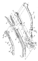
- Fig. 14 is a perspective view of another embodiment of the instrument constructed according to the present invention for applying surgical fasteners to tissue;
- Fig. 15 is an exploded perspective view of the instrument of Fig. 14;
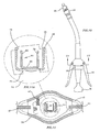
- Fig. 16 is an enlarged, partially cut away cross-section view of the insert guide of the instrument of Fig. 14;
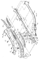
- Fig. 17 is an enlarged exploded view of the distal of the instrument of Fig. 14; and
- Fig. 18 is an enlarged view of the distal end of the elongate member and sharp tip of the instrument of Fig. 14.
-
- Referring now in specific detail to the drawings, in which like reference numerals identify similar or identical elements throughout the several views, and initially to Fig. 1, which shows one embodiment of the surgical instrument for applying a circular array of fasteners of the present invention illustrated in perspective view as
instrument 10.Instrument 10 includeselongate body portion 12 and handlesection 14.Handle section 14 includesanvil adjustment member 16, lever lockout orsafety member 18 and fastener firing levers 20.Fastener head portion 22 andanvil member 24 are disposed at the distal end ofbody portion 12. Except where noted otherwise, the materials utilized in the components of the surgical instrument of the present invention generally include such materials as polycarbonate for housing sections and related components, and stainless steel for such components which transmit forces. One preferred polycarbonate material is LEXAN® brand polycarbonate available from General Electric Company. However, equivalent alternative materials will readily come to the mind of those skilled in the art. - Referring now to Fig. 2, the various components of
instrument 10 are shown in exploded view.Instrument 10 includes body orhousing half sections 12a and 12b which are preferably molded and joined together by suitable fastening means such asrivets 28, or the like. To control axial movement ofanvil member 24, elongatedmember 30 is slidably mounted withinbody portion 12, preferably by being securely mounted tohelical cam member 32 by any suitable means such as, for example, welding or the like.Helical cam member 32 is slidably mounted withinanvil adjustment member 16 by way of bushing 34 which is securely mounted inopen end 36 ofanvil adjustment member 16.Friction member 93 is disposed adjacentanvil adjustment member 16 to prevent relatively free rotation of the anvil adjustment member. In a preferred embodiment, both the mounting ofbushing 34 and the camming ofhelical cam 32 is accomplished bycompound pin 38 which hascentral portion 38a and extendingportions Portions bores anvil adjustment member 16, respectively. Lower extendingportion 38c serves as a camming pin and fits within the helical groove formed on the surface ofhelical cam 32. Anvilapproximation indicator member 46 has extendedportion 48 and is press fitted into proximal portion 50 ofhelical cam 32.Cap 51 is attached to proximal end 52 of anvilapproximation indicator member 46.Cap 51 is preferably a colored piece which is easily visible throughopening 54 formed near the proximal end ofanvil adjustment member 16 to provide indication to the user when the anvil member is in the proper position for firing of the instrument. The distal end ofelongated member 30 is provided with means to retainanvil member 24, which will be described in more detail below. - The fastener firing mechanism of
instrument 10 includesfastener firing member 56 which is slidably mounted withinbody portion 12 preferably such thatfastener firing member 56 is disposed around elongatedmember 30.Fastener firing member 56 is preferably biased in a proximal direction by suitable biasing means such asspring 58. Fastener firing levers 20 are pivotably mounted tobody portion 12 and have extendedportions 60 which cross over each other in scissor-like fashion.Bearing block 62 is mounted onfastener firing member 56, for example, being held betweenflexible finger portions 64 and raisedportions 66 which are formed in the side walls offastener firing member 56, as best illustrated in Figs. 3 and 4.Fastener firing member 56 has bearing surfaces such astabs 68 formed at the distal portion which serve to urge a pusher member withinfastener head portion 22 in a distal direction in order to ejectsurgical fasteners 69, such as stainless steel or titanium staples, fromfastener head portion 22. - Also disposed on
instrument 10 arelever lockout member 18 and elongatemember lockout member 70.Lever lockout member 18 is preferably spring biased to the locked out position byspring 67 inslot 91. Each of these lockout members are preferably mounted oninstrument 10 in such a manner that they are fixed relative to each other and upon pivoting oflever lockout member 18, elongatemember lockout member 70 also pivots. With reference to Figs. 11A and 13A, elongatemember lockout member 70 hasshoulder portions tab 79. The function of each of these portions of elongatemember lockout member 70 will be described in further detail later herein. - Referring now to Figs. 3-9, the structural and functional details of
fastener firing member 56 andelongated member 30 will now be described in detail. In Figs. 3-5,fastener firing member 56 is shown as preferably being a generally U-shaped member formed from material which can transmit forces effectively and reliably such as stainless steel.Fastener firing member 56 hasside walls web 76. To fitfastener firing member 56 within the curved section ofbody portion 12,fastener firing member 56 has extended portions orflexible bands 72a and 74a which are preferably formed integrally withwalls Band 72a is shorter than band 74a. The difference in the length of the two bands corresponds to the amount of curvature ofbody portion 12 so that whenfastener firing member 56 is mounted inbody portion 12, the surfaces oftabs 68 form a plane parallel with the surface of the fastener pusher member (not shown). - Referring to Figs. 6-9, elongated
member 30 is shown as a U-shaped member, similar tofastener firing member 56.Elongated member 30 hasside walls web 82. However, the cross-section dimensions ofelongated member 30 are preferably such thatelongated member 30 readily fits withinfastener firing member 56. This arrangement is desirable so thatelongated member 30 andfastener firing member 56 can slide independent of each other. As withfastener firing member 56, elongatedmember 30 must also be formed to fit within the curved contour ofbody portion 12. To accomplish this curvature, elongatedmember 30 has extended portions orflexible bands walls fastener firing member 56,bands elongated member 30 are of different length.Elongated member 30 terminates at a distal end in a pair of opposedanvil retaining portions member 30 andfastener firing member 56. Such structure can be of unitary construction and have grooves to direct longitudinal movement of the channels and bands. Additionally, one or more seals (see 326a dn 326b in Fig. 15) can be disposed withinbody portion 12 to prevent the flow of gases therethrough. - To facilitate retaining
anvil member 24, and in particular, the anvil shaft therein,anvil retaining portions anvil 24,anvil retaining portions flexible finger portions portions portions flexible finger portions instrument 10. Referring temporarily back to Fig. 2, onceannular groove portion 100 ofanvil shaft 102 passes between retainingportions flexible finger portions portions annular groove 100. - In a preferred embodiment,
extended portions elongated member 30 are preferably bent until the ends ofanvil retaining portions - At the proximal end of
elongated member 30, cut outportion 83 is formed to receive elongatemember lockout member 70 when elongated member is properly positioned for firing the staples ofinstrument 10. As best illustrated in Figs. 6 and 7,cutout portion 83 is preferably formed through most ofweb 82 and continues partially upside wall 80. - The basic steps of operation are set forth in several patents, such as U.S. Patents 4,576,167 issued to Noiles, 5,005,749 issued to Aranyi, and 5,119,983 to Green et al. the contents of each of these references are hereby incorporated by reference.
- With reference to the instrument of the present invention, the user positions the tissue to be joined between
anvil 24 andfastener head portion 22.Anvil adjustment member 16 is rotated to move elongatedmember 30 andanvil 24 proximally until the user seesapproximation indicator 46 appear in opening 54 ofanvil adjustment member 16. During this step,elongate member 30 acts as a tension member as it pullsanvil 24 into position adjacentfastener head portion 22. Prior to alignment of cut out 83 inelongate member 30 andextended portion 79 ofelongate member lockout 70,lockout 70 is prevented from pivoting by contact betweenextended portion 79 andelongate member 30. When cut out 83 is positioned adjacentextended portion 79 ofelongate member lockout 70, as further described below,lever lockout member 18 andelongate member lockout 70 are able to be pivoted by depressing, usually with the thumb, onlever lockout member 18.Members lever lockout member 18 is pivoted by the user, fastener firing levers 20 are depressed to urgefastener firing member 56 in a distal direction. This motion is accomplished by the camming effect ofextended portions 60 of fastener firing levers 20 on bearingblock 62 the distal movement offastener firing member 56 urges fastener pusher members to ejectfasteners 69 fromfastener head portion 22. During this step,fastener firing member 56 acts as a compression member as it ejectsfasteners 69. - With the above operational description of
instrument 10 as a general base of the overall operation, the operation ofelongate member lockout 70 will now be described in detail with reference to Figs. 10-13. Once the user hasinstrument 10 inserted and the tissue to be joined is properly situated about the distal end of the instrument,anvil 24 is approximated to its proper position by rotation ofanvil adjustment member 16,instrument 10 is positioned for firing, as shown in Fig. 10. In that position, however,fastener firing member 56 is still blocked from movement due tolever lockout member 18 still being oriented in the "safety on" position, i.e., lever locking extended portions 104 and 106 (Fig. 2) are aligned with the structure oflevers 20 so that they cannot be depressed. Pivoting oflever lockout member 18 is prevented when elongatedmember 30 is out of the desired approximation range for firing the staples. - With reference to Figs. 2-7, 11 and 13, prevention of the ability to pivot
lever lockout member 18 is accomplished by the relative position ofelongated member 30 and thus the approximation ofanvil 24. Whenanvil 24 is not properly approximated,side wall 80 andweb 82 ofelongated member 30 preventextended portion 79 ofelongate member lockout 70 from moving further inward (Fig. 11). However, once elongatedmember 30 is properly positioned, i.e., cut out 83 is aligned withextended portion 79 ofelongate member lockout 70, thenlever lockout member 18 which is fixedly secured to elongatemember lockout member 70, can be pivoted, as shown in Fig. 13. Whenlockout 70 is pivoted,shoulder portions lockout 70 are moved out ofnotches 77 of fastener firing member 56 (Figs. 3 and 4). This enables fastener firing levers 20 to be pivoted toward each other as shown in Fig. 12, thereby movingfastener firing member 56 distally and ejectingfasteners 69 fromfastener head portion 22. As can be seen in Figs. 13 and 13A oncelever lockout 18, and elongatemember lockout 70 are pivoted by the user, inwardly extendingportion 79 oflockout 70 enters into cut out 83 (Figs. 6 and 7) and blocks elongatedmember 30 from movement in either a proximal or distal direction. - Referring now to Figs. 14-18, another embodiment of the present invention shown as
instrument 210 will now be described. For purposes of clarity, components of the instrument of Figs. 14-18 which are similar or identical to those of the embodiment for Figs. 1-13 have been labeled by adding 200 to the reference numerals of the earlier embodiment. For example,anvil shaft 102 of Fig. 2 corresponds toanvil shaft 302 of Fig. 15. - Referring now to Fig. 14 in conjunction with Fig. 15,
instrument 210 includesinsert guide 320 which is preferably molded of a polycarbonate material such as LEXAN® available from the General Electric Company.Insert guide 320 is preferably molded to conform to the curvature ofhousing half sections elongate member 230 andfastener firing member 256. Referring temporarily to Fig. 16,insert guide 320 is illustrated in a partially cut away section to show the guide tracks which receiveelongate member 230 andfastener firing member 256 therein. Specifically, outer guide tracks 322 are molded to receivesidewalls side walls elongate member 30 therein.Insert guide 320 thereby provides structural support upon longitudinal motion of eitherelongate member 230 orfastener firing member 256, particularly at the point of curvature thereof.Insert guide 320 effectively reduces possible force transmission losses upon operation ofinstrument 210. - In order to provide an internal seal in
body portion 212, sealhalf sections insert guide 320.Seal half sections housing half sections half sections elongate member 230 andfastener firing member 256 so as to form a seal between the internal section of theinstrument 210 which is distal of theseal half sections instrument 210 which are proximal ofseal half sections - Referring now to figure 15 in conjunction with Fig. 17, additional features of the present invention are illustrated therein which will now be described. An adjusting member such as
collar 328 is mounted between the distal end ofhousing 212 and the proximal end of fastenerhead portion assembly 222.Collar 328 has ratchetteeth 330 formed on an inner surface thereof at the proximal end. Ratchetteeth 330 cooperate withratchet teeth 332 formed on the distal end ofhousing half sections teeth collar 328 in a single direction. Also formed oncollar 328 are cammingsurfaces camming surfaces fastener head portion 222. A purpose ofcollar 328 is to provide for post instrument assembly adjustment of the relative longitudinal positioning of fastenerhead portion assembly 222 with respect to the distal end ofbody portion 212. This adjustment capability is important so thatinstrument 210 may be calibrated to insure the proper positioning ofanvil member 224 whencap 251 of anvilapproximation indicator member 246 is positioned within opening 254 so as to indicate thatinstrument 210 is ready for firing ofsurgical staples 269. Onceinstrument 210 is properly calibrated,collar member 328 may be fixedly secured to the distal end ofbody portion 212 so thatcollar 328 is not permitted to rotate with respect thereto. This attachment may be accomplished by known suitable means such as, for example, bonding and/or by the use of a fastener such as a screw or a pin. - Another important feature illustrated in Fig. 17 provides protection against over crimping of
surgical staples 269 upon firing ofinstrument 210. Pusher back 342 is provided with longitudinally extendingportions 344 which are configured to fit inside ofknife ring 346 and are preferably sized to abut against a surface portion, such ascut ring 345, ofanvil 224 upon firing ofinstrument 210. Whenportions 344 of pusher back 342 contact a portion ofanvil 224,pusher fingers 252 are prevented from traveling further, thereby limiting the degree to whichsurgical staples 269 may be crimped againstanvil 224. - In another feature of the present invention, referring now Fig. 15 in conjunction with Fig. 18,
elongate member 230 hastip 354 formed at the distal end to facilitate puncturing of tissue as desired by the user ofinstrument 210.Tip 354 is preferably sharp and formed by known methods such as, for example, grinding with suitable abrasives.Tip 354 is formed such that a hollow passageway oropening 356 is formed which passes longitudinally through the distal end portion ofelongate member 230. Opening 356 onelongate member 230 is preferably sized so that it can receiveshaft 302 ofanvil 224 so thatanvil 224 may be retained by the distal end portion ofelongate member 230 in a similar manner as set forth above forelongate member 30 andanvil 24 for the embodiment of Figs. 1-13. To avoid inadvertent lateral contact with tip 354 a protective cover is provided, such ascover 358 which is preferably formed of a deformable elastomeric material. Cover 358 is provided withy raisedportions 360 which corresponds to bores 362 formed onelongate member 230 proximal oftip 354. In use, whenelongate member 230 is extended pasthead portion assembly 22,cover 358 deflects upon contact with tissue to exposetip 354. Aftertip 354 and cover 358 pass through the tissue, cover 358 returns to a position which protectstip 354, thereby providing means for preventing inadvertent trauma bytip 354 to surrounding tissue. - The operation of
instrument 210 is similar to that ofinstrument 10 except as noted hereinabove. Accordingly, no separate description of the operation ofinstrument 210 will be provided at this point. - The claims which follow identify embodiments of the invention additional to those described in detail above.
Claims (16)
- A surgical instrument for applying at least one array of fasteners comprising:a handle section;a curved body portion extending from the handle section;a fastener head portion connected to the body portion and including a plurality of fasteners;an elongated member operatively connected to the handle section and extending at least partially through the curved body portion, the elongated member including a distal end including at least two flexible bands, the elongated member being movable between a first position and a second position; andan anvil member attached to the at least two flexible bands of the elongated member and being adapted to form the plurality of fasteners.
- A surgical instrument according to Claim 1, further including at least one lever member associated with the handle section and operatively associated with the fastener head portion.
- A surgical instrument according to Claim 1 or 2, wherein the flexible bands are of different lengths to compensate for the curvature of the curved body portion.
- A surgical instrument according to any of the preceding claims, wherein the elongated member includes an open-sided channel section.
- A surgical instrument according to any of the preceding claims, wherein the distal end of each of the flexible bands of the elongated member includes an anvil retaining portion.
- A surgical instrument according to Claim 5, wherein each anvil retaining portion is semi-circular in shape.
- A surgical instrument according to Claim 5 or 6, wherein each anvil retaining portion includes a flexible finger portion including a raised portion formed thereon, the retaining portions being dimensioned to seat in an annular groove portion of an anvil shaft of the anvil member to removably attach the anvil member to the at least two finger portions.
- A surgical instrument for applying at least one circular array of fasteners, comprising:a body portion including a proximal end and a distal end, the body portion having a handle section at the proximal end and an elongated housing section extending from the distal end;a fastener head portion connected to said body portion and including a plurality of fasteners;at least one movable lever member associated with said handle section and operatively connected to said fastener head portion;an elongated U-shaped member forming an open sided channel section along a portion thereof, the elongated U-shaped member extending from said handle section and at least partially through said elongated housing section and having at least two finger portions extending from a distal end thereof, said U-shaped member being movable between a first position and a second position;an anvil member attached to said at least two finger portions of said elongated U-shaped member, said anvil member being adapted for forming said plurality of fasteners.
- A surgical instrument as recited in Claim 8, wherein said anvil member is removably attached to said at least two finger portions.
- A surgical instrument according to Claim 8 or 9, wherein the distal end of the elongated U-shaped member includes at least two flexible bands, the at lest two finger portions being positioned on the at least two flexible bands.
- A surgical instrument as recited in any one of Claims 8 to 10, wherein said at least two finger portions have an arcuate cross section shape.
- A surgical instrument as recited in any one of Claims 8 to 11, further comprising locking means operatively associated with said U-shaped member and movable between at least a first position wherein said U-shaped member is operatively movable and a second position wherein said U-shaped member is prevented from being operatively movable.
- A surgical instrument as recited in Claim 12, wherein said locking means is further operatively associated with said at least one movable lever member such that when said locking means is in said first position, said U-shaped member is movable and said plurality of fasteners is prevented from being expelled from said fastener head portion and when said locking means is in said second position, said U-shaped member is locked and said plurality of fasteners are expellable from said fastener head portion.
- A surgical instrument as recited in Claim 12 or 13, wherein said locking means is biased to remain initially in said first position.
- A surgical instrument according to any one of claims 8 to 14, wherein the body portion is curved.
- A surgical instrument according to Claim 15, wherein the flexible bands are of different lengths to compensate for the curvature of the curved body portion.
Applications Claiming Priority (4)
| Application Number | Priority Date | Filing Date | Title |
|---|---|---|---|
| US24951294A | 1994-05-26 | 1994-05-26 | |
| US249512 | 1994-05-26 | ||
| EP95107521A EP0695532B1 (en) | 1994-05-26 | 1995-05-17 | Circular anastomosis device |
| EP01126594A EP1175868B1 (en) | 1994-05-26 | 1995-05-17 | Circular anastomosis device |
Related Parent Applications (1)
| Application Number | Title | Priority Date | Filing Date |
|---|---|---|---|
| EP01126594A Division EP1175868B1 (en) | 1994-05-26 | 1995-05-17 | Circular anastomosis device |
Publications (3)
| Publication Number | Publication Date |
|---|---|
| EP1354560A2 true EP1354560A2 (en) | 2003-10-22 |
| EP1354560A3 EP1354560A3 (en) | 2004-04-07 |
| EP1354560B1 EP1354560B1 (en) | 2009-05-06 |
Family
ID=22943775
Family Applications (4)
| Application Number | Title | Priority Date | Filing Date |
|---|---|---|---|
| EP01126595A Expired - Lifetime EP1175869B1 (en) | 1994-05-26 | 1995-05-17 | Circular anastomosis device |
| EP03016597A Expired - Lifetime EP1354560B1 (en) | 1994-05-26 | 1995-05-17 | Circular anastomosis device |
| EP01126594A Expired - Lifetime EP1175868B1 (en) | 1994-05-26 | 1995-05-17 | Circular anastomosis device |
| EP95107521A Expired - Lifetime EP0695532B1 (en) | 1994-05-26 | 1995-05-17 | Circular anastomosis device |
Family Applications Before (1)
| Application Number | Title | Priority Date | Filing Date |
|---|---|---|---|
| EP01126595A Expired - Lifetime EP1175869B1 (en) | 1994-05-26 | 1995-05-17 | Circular anastomosis device |
Family Applications After (2)
| Application Number | Title | Priority Date | Filing Date |
|---|---|---|---|
| EP01126594A Expired - Lifetime EP1175868B1 (en) | 1994-05-26 | 1995-05-17 | Circular anastomosis device |
| EP95107521A Expired - Lifetime EP0695532B1 (en) | 1994-05-26 | 1995-05-17 | Circular anastomosis device |
Country Status (4)
| Country | Link |
|---|---|
| EP (4) | EP1175869B1 (en) |
| CA (1) | CA2147800C (en) |
| DE (4) | DE69531966T2 (en) |
| ES (4) | ES2177591T3 (en) |
Cited By (148)
| Publication number | Priority date | Publication date | Assignee | Title |
|---|---|---|---|---|
| EP2286740A1 (en) * | 2009-08-19 | 2011-02-23 | Tyco Healthcare Group LP | Surgical stapler |
| US8281974B2 (en) | 2009-01-14 | 2012-10-09 | Tyco Healthcare, Group LP | Surgical stapler with suture locator |
| US8424535B2 (en) | 2008-11-06 | 2013-04-23 | Covidien Lp | Circular surgical stapler with mating anvil and shell assembly |
| US8708212B2 (en) | 2011-10-18 | 2014-04-29 | Covidien Lp | Tilt top anvil with torsion spring |
| US8931680B2 (en) | 2009-07-11 | 2015-01-13 | Covidien Lp | Surgical instrument with safety mechanism |
| US9010605B2 (en) | 2012-01-12 | 2015-04-21 | Covidien Lp | Sliding sleeve for circular stapling instrument reloads |
| US9016547B2 (en) | 2011-10-26 | 2015-04-28 | Covidien Lp | EEA tilt top anvil with ratchet/locking mechanism |
| US9022274B2 (en) | 2012-02-15 | 2015-05-05 | Covidien Lp | Circular stapler with increased lumen diameter |
| US9351724B2 (en) | 2013-01-11 | 2016-05-31 | Covidien Lp | Circular stapling instrument |
| US9351734B2 (en) | 2012-06-19 | 2016-05-31 | Covidien Lp | Spring loaded anvil retainer |
| US9517070B2 (en) | 2013-11-13 | 2016-12-13 | Covidien Lp | Anvil assembly and delivery system |
| US9532780B2 (en) | 2013-06-12 | 2017-01-03 | Covidien Lp | EEA anvil snap ring activator |
| US9554802B2 (en) | 2013-11-13 | 2017-01-31 | Covidien Lp | Anvil assembly with frangible retaining member |
| US9572572B2 (en) | 2012-11-09 | 2017-02-21 | Covidien Lp | Circular stapler mechanical lockout |
| US9592056B2 (en) | 2013-03-14 | 2017-03-14 | Covidien Lp | Powered stapling apparatus |
| US9668740B2 (en) | 2013-06-14 | 2017-06-06 | Covidien Lp | Anvil assembly with sliding sleeve |
| US9675359B2 (en) | 2012-10-10 | 2017-06-13 | Covidien Lp | Surgical instrument with preload assembly |
| US9693773B2 (en) | 2013-09-11 | 2017-07-04 | Covidien Lp | Anvil assembly with sliding sleeve |
| US9707005B2 (en) | 2014-02-14 | 2017-07-18 | Ethicon Llc | Lockout mechanisms for surgical devices |
| US9750503B2 (en) | 2013-07-11 | 2017-09-05 | Covidien Lp | Methods and devices for performing a surgical anastomosis |
| US9757133B2 (en) | 2014-07-09 | 2017-09-12 | Covidien Lp | Methods and devices for performing a surgical anastomosis |
| US9855045B2 (en) | 2014-12-09 | 2018-01-02 | Covidien Lp | Anvil assembly delivery system |
| US9861367B2 (en) | 2014-06-24 | 2018-01-09 | Covidien Lp | Anvil assembly delivery systems |
| US9867619B2 (en) | 2014-06-24 | 2018-01-16 | Covidien Lp | System for delivering an anvil assembly to a surgical site |
| US9913643B2 (en) | 2014-05-09 | 2018-03-13 | Covidien Lp | Interlock assemblies for replaceable loading unit |
| US9974536B2 (en) | 2015-07-02 | 2018-05-22 | Covidien Lp | Anvil assemblies and delivery systems |
| US9980730B2 (en) | 2015-09-21 | 2018-05-29 | Covidien Lp | Loading unit locking collar with rotational actuated release |
| US9987001B2 (en) | 2015-06-12 | 2018-06-05 | Covidien Lp | Surgical anastomosis apparatus |
| US10022126B2 (en) | 2015-01-07 | 2018-07-17 | Covidien Lp | Loading unit locking collar |
| US10039549B2 (en) | 2015-01-07 | 2018-08-07 | Covidien Lp | Loading unit retention clip for surgical stapling instrument |
| US10085756B2 (en) | 2015-07-24 | 2018-10-02 | Covidien Lp | Anvil assembly and anvil assembly delivery system |
| US10085744B2 (en) | 2014-12-08 | 2018-10-02 | Covidien Lp | Loading unit attachment band for surgical stapling instrument |
| US10111684B2 (en) | 2015-09-25 | 2018-10-30 | Covidien Lp | Adapter assembly including a removable trocar assembly |
| US10111668B2 (en) | 2015-07-02 | 2018-10-30 | Covidien Lp | Anvil assembly with snap backup ring |
| US10117656B2 (en) | 2015-01-07 | 2018-11-06 | Covidien Lp | Loading unit locking collar |
| US10117655B2 (en) | 2015-07-22 | 2018-11-06 | Covidien Lp | Loading unit locking band for surgical stapling instrument |
| US10117675B2 (en) | 2015-07-28 | 2018-11-06 | Covidien Lp | Trocar tip protector |
| US10178994B2 (en) | 2013-03-15 | 2019-01-15 | Covidien Lp | Surgical stapling apparatus with reusable components |
| US10213205B2 (en) | 2012-07-06 | 2019-02-26 | Covidien Lp | T-slot tilt anvil for circular stapling instrument |
| US10271843B2 (en) | 2013-06-17 | 2019-04-30 | Covidien Lp | Surgical instrument with lockout mechanism |
| US10342534B2 (en) | 2017-03-23 | 2019-07-09 | Covidien Lp | Surgical stapling device with releasable knife carrier |
| US10390835B2 (en) | 2015-12-10 | 2019-08-27 | Covidien Lp | Surgical fastener apparatus with linear position sensor |
| US10405864B2 (en) | 2014-07-04 | 2019-09-10 | Covidien Lp | Loading unit with shipping member for surgical stapling device |
| US10426480B2 (en) | 2015-04-29 | 2019-10-01 | Covidien Lp | Cutting ring assembly with rigid cutting member |
| US10426470B2 (en) | 2016-11-04 | 2019-10-01 | Covidien Lp | Stapling device with releasable knife carrier |
| US10499922B2 (en) | 2016-11-04 | 2019-12-10 | Covidien Lp | Stapling device with self-releasing knife carrier pusher |
| US10499916B2 (en) | 2014-12-11 | 2019-12-10 | Covidien Lp | Surgical stapling loading unit |
| US10507022B2 (en) | 2014-06-12 | 2019-12-17 | Covidien Lp | Surgical stapling apparatus |
| US10512466B2 (en) | 2015-11-05 | 2019-12-24 | Covidien Lp | Adapter assembly for surgical device |
| US10517601B2 (en) | 2015-02-15 | 2019-12-31 | Covidien Lp | Surgical stapling device with firing indicator of unitary construction |
| US10524797B2 (en) | 2016-01-13 | 2020-01-07 | Covidien Lp | Adapter assembly including a removable trocar assembly |
| US10542993B2 (en) | 2017-02-24 | 2020-01-28 | Covidien Lp | Anvil assembly of circular stapling device including alignment splines |
| US10542992B2 (en) | 2015-10-19 | 2020-01-28 | Covidien Lp | Loading unit with stretchable bushing |
| US10542985B2 (en) | 2014-12-17 | 2020-01-28 | Covidien Lp | Surgical stapling device with firing indicator |
| US10595871B2 (en) | 2016-05-10 | 2020-03-24 | Covidien Lp | Insertion instrument, adapter assemblies and protector assemblies for a flexible circular stapler |
| US10603042B2 (en) | 2016-02-10 | 2020-03-31 | Covidien Lp | Flexible circular stapler |
| US10695069B2 (en) | 2017-08-23 | 2020-06-30 | Covidien Lp | Circular stapling device with offset spline tip |
| US10772627B2 (en) | 2014-12-11 | 2020-09-15 | Covidien Lp | Stapler with auto-matic lockout mechanism |
| US10828026B2 (en) | 2017-08-08 | 2020-11-10 | Covidien Lp | Tiltable anvil assembly |
| US10842495B2 (en) | 2015-10-21 | 2020-11-24 | Covidien Lp | Annular knife for a surgical stapler |
| US10874399B2 (en) | 2016-02-04 | 2020-12-29 | Covidien Lp | Circular stapler with visual indicator mechanism |
| US10881409B2 (en) | 2017-05-02 | 2021-01-05 | Covidien Lp | Rotation assembly for a surgical device |
| US10881408B2 (en) | 2015-04-22 | 2021-01-05 | Covidien Lp | Interlock assembly for replaceable loading units |
| US10932784B2 (en) | 2017-06-09 | 2021-03-02 | Covidien Lp | Handheld electromechanical surgical system |
| US10932783B2 (en) | 2015-11-13 | 2021-03-02 | Covidien Lp | Circular stapler with audible indicator mechanism |
| US10952734B2 (en) | 2018-04-23 | 2021-03-23 | Covidien Lp | Stapling device with cut ring biasing member |
| US10973522B2 (en) | 2015-10-20 | 2021-04-13 | Covidien Lp | Circular stapler with tissue gap indicator assembly |
| US10973544B2 (en) | 2018-10-02 | 2021-04-13 | Covidien Lp | Retaining mechanism for trocar assembly |
| US10987107B2 (en) | 2017-07-05 | 2021-04-27 | Covidien Lp | Surgical stapling device |
| US11020119B2 (en) | 2015-12-07 | 2021-06-01 | Covidien Lp | Anvil assembly and delivery system |
| US11045199B2 (en) | 2017-06-09 | 2021-06-29 | Covidien Lp | Handheld electromechanical surgical system |
| US11065005B2 (en) | 2018-11-07 | 2021-07-20 | Covidien Lp | Reload assembly for a circular stapling device |
| US11071549B2 (en) | 2017-03-23 | 2021-07-27 | Covidien Lp | Circular stapling device with alignment splines |
| US11090054B2 (en) | 2017-08-07 | 2021-08-17 | Covidien Lp | Stapling device with resettable tilt anvil assembly |
| US11116507B2 (en) | 2017-03-09 | 2021-09-14 | Covidien Lp | End effector assembly for a circular stapler apparatus |
| US11123101B2 (en) | 2019-07-05 | 2021-09-21 | Covidien Lp | Retaining mechanisms for trocar assemblies |
| US11141163B2 (en) | 2018-10-04 | 2021-10-12 | Covidien Lp | Circular stapling device with anvil rotation locking structure |
| US11141162B2 (en) | 2016-07-08 | 2021-10-12 | Covidien Lp | Loading unit locking collar with linearly actuated release |
| US11147561B2 (en) | 2018-11-28 | 2021-10-19 | Covidien Lp | Reload assembly for a circular stapling device |
| US11166728B2 (en) | 2019-02-08 | 2021-11-09 | Covidien Lp | Reload assembly for a circular stapling device |
| US11192227B2 (en) | 2019-07-16 | 2021-12-07 | Covidien Lp | Reload assembly for circular stapling devices |
| US11197676B2 (en) | 2018-06-28 | 2021-12-14 | Covidien Lp | Tie-down method for anvil assembly delivery system |
| US11234703B2 (en) | 2017-09-01 | 2022-02-01 | Covidien Lp | Circular stapling device with position ribs |
| US11241234B2 (en) | 2018-08-14 | 2022-02-08 | Covidien Lp | Anvil assembly with self-retaining backup member |
| US11241232B2 (en) | 2017-01-24 | 2022-02-08 | Covidien Lp | Surgical stapling device with resettable anvil assembly |
| US11246599B2 (en) | 2019-04-25 | 2022-02-15 | Covidien Lp | End effector for circular stapling instrument |
| US11253255B2 (en) | 2019-07-26 | 2022-02-22 | Covidien Lp | Knife lockout wedge |
| US11272998B2 (en) | 2020-03-04 | 2022-03-15 | Covidien Lp | Strain gage fixation in tension |
| US11298152B2 (en) | 2020-02-28 | 2022-04-12 | Covidien Lp | Trocar retaining mechanism including band support |
| US11317945B2 (en) | 2019-04-16 | 2022-05-03 | Covidien Lp | Trocar assemblies for adapter assemblies for surgical stapling instruments |
| US11324507B2 (en) | 2017-11-03 | 2022-05-10 | Covidien Lp | Device and method for attachment of a stomal sleeve |
| US11331782B2 (en) | 2019-03-01 | 2022-05-17 | Covidien Lp | Reload assembly for a circular stapling device |
| US11337701B2 (en) | 2019-03-01 | 2022-05-24 | Covidien Lp | Devices and methods for assembling adapter assemblies |
| US11344330B2 (en) | 2019-04-16 | 2022-05-31 | Covidien Lp | Trocar assemblies for adapter assemblies for surgical stapling instruments |
| US11350939B2 (en) | 2020-03-24 | 2022-06-07 | Covidien Lp | Retaining mechanisms for trocar assemblies |
| US11357509B2 (en) | 2019-07-11 | 2022-06-14 | Covidien Lp | Reload assembly for a circular stapling device |
| US11382630B2 (en) | 2020-02-25 | 2022-07-12 | Covidien Lp | Surgical stapling device with two part knife assembly |
| US11382629B2 (en) | 2017-03-09 | 2022-07-12 | Covidien Lp | Surgical stapling device with audible indicator mechanism |
| US11389263B2 (en) | 2018-12-13 | 2022-07-19 | Covidien Lp | Lockout mechanisms for surgical instruments |
| US11399825B2 (en) | 2019-10-28 | 2022-08-02 | Covidien Lp | Reload assembly with knife carrier lockout |
| US11399838B2 (en) | 2019-04-22 | 2022-08-02 | Covidien Lp | Reload assembly for circular stapling devices |
| US11419631B2 (en) | 2019-04-16 | 2022-08-23 | Covidien Lp | Trocar assemblies for adapter assemblies for surgical stapling instruments |
| US11426169B2 (en) | 2020-03-24 | 2022-08-30 | Covidien Lp | Retaining mechanisms for trocar assemblies |
| US11426170B2 (en) | 2020-03-24 | 2022-08-30 | Covidien Lp | Retaining mechanisms for trocar assemblies |
| US11446035B2 (en) | 2019-06-24 | 2022-09-20 | Covidien Lp | Retaining mechanisms for trocar assemblies |
| US11452522B2 (en) | 2016-08-15 | 2022-09-27 | Covidien Lp | Circular stapling device with articulating anvil retainer assembly |
| US11457921B2 (en) | 2019-03-26 | 2022-10-04 | Covidien Lp | Anvil assembly for surgical stapling instrument |
| US11464510B2 (en) | 2019-07-26 | 2022-10-11 | Covidien Lp | Reload assembly with knife carrier lockout |
| US11490894B1 (en) | 2021-05-12 | 2022-11-08 | Covidien Lp | Surgical device with grease filter |
| US11497501B2 (en) | 2018-03-26 | 2022-11-15 | Covidien Lp | Circular stapling device with A-frame splines |
| US11517317B2 (en) | 2020-01-06 | 2022-12-06 | Covidien Lp | Trocar release assemblies for a surgical stapler |
| US11523828B2 (en) | 2020-01-28 | 2022-12-13 | Covidien Lp | Sealed reload assembly for stapling device |
| US11529144B2 (en) | 2019-02-22 | 2022-12-20 | Covidien Lp | Encapsulated plug assembly for electromechanical surgical devices |
| US11534164B2 (en) | 2019-04-05 | 2022-12-27 | Covidien Lp | Strain gauge stabilization in a surgical device |
| US11547405B2 (en) | 2020-05-22 | 2023-01-10 | Covidien Lp | Surgical stapling device |
| US11547438B2 (en) | 2020-02-24 | 2023-01-10 | Covidien Lp | Tip protector for ensuring trocar insertion |
| US11547412B2 (en) | 2020-07-22 | 2023-01-10 | Covidien Lp | Surgical instruments and methods of assembly |
| US11547411B2 (en) | 2019-02-22 | 2023-01-10 | Covidien Lp | Anastomosis wound protector |
| US11553921B2 (en) | 2020-07-15 | 2023-01-17 | Covidien Lp | Surgical stapling device with flexible shaft |
| US11553920B2 (en) | 2021-05-03 | 2023-01-17 | Covidien Lp | Trocar retainer assembly for surgical stapler |
| US11553918B2 (en) | 2019-12-16 | 2023-01-17 | Covidien Lp | Reload assembly with knife carrier lockout |
| US11564691B2 (en) | 2018-08-24 | 2023-01-31 | Covidien Lp | Powered circular stapling device |
| US11596400B2 (en) | 2017-06-09 | 2023-03-07 | Covidien Lp | Handheld electromechanical surgical system |
| US11596410B2 (en) | 2019-04-05 | 2023-03-07 | Covidien Lp | Surgical stapling device |
| US11612400B2 (en) | 2021-05-24 | 2023-03-28 | Covidien Lp | Trocar assembly with bearing assembly for load sharing |
| US11622767B2 (en) | 2020-02-19 | 2023-04-11 | Covidien Lp | Sealed trocar assembly for stapling device |
| US11627966B2 (en) | 2020-08-26 | 2023-04-18 | Covidien Lp | Surgical stapling device |
| US11627967B2 (en) | 2020-11-23 | 2023-04-18 | Covidien Lp | Trans-anastomotic insertion device |
| US11642131B2 (en) | 2021-05-17 | 2023-05-09 | Covidien Lp | Devices and methods for shortening a rectal stump during a lower anterior resection procedure |
| US11653925B2 (en) | 2020-05-21 | 2023-05-23 | Covidien Lp | Tissue relaxation monitoring for optimized tissue stapling |
| US11660116B2 (en) | 2019-04-16 | 2023-05-30 | Covidien Lp | Trocar assemblies for adapter assemblies for surgical stapling instruments |
| US11678885B2 (en) | 2017-01-25 | 2023-06-20 | Covidien Lp | Circular stapling device and method of use |
| US11690624B2 (en) | 2019-06-21 | 2023-07-04 | Covidien Lp | Reload assembly injection molded strain gauge |
| US11712509B2 (en) | 2020-10-02 | 2023-08-01 | Covidien Lp | Seal assembly for circular stapling instrument |
| US11717299B2 (en) | 2021-10-12 | 2023-08-08 | Covidien Lp | Surgical stapling device with probiotics |
| US11730481B2 (en) | 2020-01-06 | 2023-08-22 | Covidien Lp | Assemblies for retaining a trocar assembly |
| US11737759B2 (en) | 2021-08-05 | 2023-08-29 | Covidien Lp | Surgical stapling device accommodating prolapsed tissue |
| US11744592B2 (en) | 2021-08-05 | 2023-09-05 | Covidien Lp | Handheld electromechanical stapler with tissue thickness detection |
| US11779343B2 (en) | 2020-02-26 | 2023-10-10 | Covidien Lp | Staple reload assembly with releasable knife |
| US11786241B2 (en) | 2021-02-16 | 2023-10-17 | Covidien Lp | Surgical stapling device including a hydraulic staple formation mechanism |
| US11801054B2 (en) | 2020-09-22 | 2023-10-31 | Covidien Lp | Surgical stapler with oval tool assembly |
| US11819208B2 (en) | 2021-08-05 | 2023-11-21 | Covidien Lp | Handheld electromechanical surgical device with strain gauge drift detection |
| US11839378B2 (en) | 2019-04-19 | 2023-12-12 | Covidien Lp | Circular stapling instruments |
| US11877750B2 (en) | 2021-01-21 | 2024-01-23 | Covidien Lp | Surgical stapler with powered and manual functions |
| US11877744B2 (en) | 2020-08-14 | 2024-01-23 | Covidien Lp | Low-cost powered stapler with end stop selection |
| US11883028B2 (en) | 2021-09-08 | 2024-01-30 | Covidien Lp | Systems and methods for post-operative anastomotic leak detection |
| US11896233B2 (en) | 2019-05-31 | 2024-02-13 | Covidien Lp | Circular stapling device |
| US11911038B2 (en) | 2020-01-13 | 2024-02-27 | Covidien Lp | Cut optimization for excessive tissue conditions |
Families Citing this family (8)
| Publication number | Priority date | Publication date | Assignee | Title |
|---|---|---|---|---|
| US6454702B1 (en) | 1999-10-14 | 2002-09-24 | Scimed Life Systems, Inc. | Endoscope and endoscopic instrument system having reduced backlash when moving the endoscopic instrument within a working channel of the endoscope |
| GB0818101D0 (en) | 2008-10-03 | 2008-11-05 | Femcare Nikomed Ltd | Applicator for surgical clips |
| CN103126738B (en) * | 2013-03-22 | 2015-07-15 | 常州华森医疗器械有限公司 | With-needle anorectum stomach-intestine anastomat with movable head capable of absorbing biological nails |
| CN104367360B (en) * | 2014-10-22 | 2016-09-21 | 重庆康美唯外科器械有限公司 | A kind of Medical stapler and insurance instruction system thereof |
| CN105982710A (en) * | 2015-01-28 | 2016-10-05 | 常州安康医疗器械有限公司 | Novel continuously variable locking mechanism of circular stapler |
| CN105310747B (en) * | 2015-12-05 | 2017-09-12 | 北京天钥医疗器械有限公司 | A kind of anastomat for circumcision with spill seat lockable mechanism |
| CN112890897B (en) * | 2021-01-18 | 2022-11-15 | 江苏钱璟医疗器械有限公司 | Point cutting anastomat with replaceable cutter head |
| CN112674843B (en) * | 2021-02-02 | 2021-10-26 | 山东省千佛山医院 | Partial arc cutting anastomat |
Citations (6)
| Publication number | Priority date | Publication date | Assignee | Title |
|---|---|---|---|---|
| US4351466A (en) | 1980-10-16 | 1982-09-28 | United States Surgical Corporation | Disposable instrument for surgical fastening |
| US4576167A (en) | 1981-09-03 | 1986-03-18 | United States Surgical Corporation | Surgical stapler apparatus with curved shaft |
| US4603693A (en) | 1977-05-26 | 1986-08-05 | United States Surgical Corporation | Instrument for circular surgical stapling of hollow body organs and disposable cartridge therefor |
| US5005749A (en) | 1988-07-01 | 1991-04-09 | United States Surgical Corp. | Anastomosis surgical stapling instrument |
| US5104025A (en) | 1990-09-28 | 1992-04-14 | Ethicon, Inc. | Intraluminal anastomotic surgical stapler with detached anvil |
| US5119983A (en) | 1987-05-26 | 1992-06-09 | United States Surgical Corporation | Surgical stapler apparatus |
Family Cites Families (14)
| Publication number | Priority date | Publication date | Assignee | Title |
|---|---|---|---|---|
| GB1121673A (en) * | 1965-08-26 | 1968-07-31 | N Isseldovatelsky Iex Khirurgi | Improvements in or relating to a surgical instrument for suturing hollow organs |
| US3593903A (en) * | 1968-07-12 | 1971-07-20 | Vnii Khirurgicheskoi Apparatur | Surgical instrument for suturing hollow organs in infants |
| US4319576A (en) * | 1980-02-26 | 1982-03-16 | Senco Products, Inc. | Intralumenal anastomosis surgical stapling instrument |
| US4606343A (en) * | 1980-08-18 | 1986-08-19 | United States Surgical Corporation | Self-powered surgical fastening instrument |
| US4485817A (en) * | 1982-05-28 | 1984-12-04 | United States Surgical Corporation | Surgical stapler apparatus with flexible shaft |
| AU5476486A (en) * | 1985-03-14 | 1986-09-18 | Hospital Products Ltd. | Surgical stapling instrument |
| US4776506A (en) * | 1986-11-13 | 1988-10-11 | United States Surgical Corporation | Surgical stapler apparatus |
| US5104382A (en) * | 1991-01-15 | 1992-04-14 | Ethicon, Inc. | Trocar |
| US5152754A (en) * | 1991-02-15 | 1992-10-06 | Minnesota Mining And Manufacturing Company | Trocar |
| US5137198A (en) * | 1991-05-16 | 1992-08-11 | Ethicon, Inc. | Fast closure device for linear surgical stapling instrument |
| GR920100358A (en) * | 1991-08-23 | 1993-06-07 | Ethicon Inc | Surgical anastomosis stapling instrument. |
| DE69217808T2 (en) * | 1991-10-18 | 1997-07-24 | United States Surgical Corp | Device for attaching surgical fasteners |
| US5271543A (en) * | 1992-02-07 | 1993-12-21 | Ethicon, Inc. | Surgical anastomosis stapling instrument with flexible support shaft and anvil adjusting mechanism |
| CA2107848C (en) * | 1992-10-09 | 2005-04-12 | Frank J. Viola | Surgical fastener applying apparatus |
-
1995
- 1995-04-25 CA CA002147800A patent/CA2147800C/en not_active Expired - Lifetime
- 1995-05-17 DE DE69531966T patent/DE69531966T2/en not_active Expired - Lifetime
- 1995-05-17 EP EP01126595A patent/EP1175869B1/en not_active Expired - Lifetime
- 1995-05-17 ES ES95107521T patent/ES2177591T3/en not_active Expired - Lifetime
- 1995-05-17 DE DE69527680T patent/DE69527680T2/en not_active Expired - Lifetime
- 1995-05-17 EP EP03016597A patent/EP1354560B1/en not_active Expired - Lifetime
- 1995-05-17 DE DE69531417T patent/DE69531417T2/en not_active Expired - Lifetime
- 1995-05-17 ES ES01126594T patent/ES2199198T3/en not_active Expired - Lifetime
- 1995-05-17 DE DE69535950T patent/DE69535950D1/en not_active Expired - Lifetime
- 1995-05-17 EP EP01126594A patent/EP1175868B1/en not_active Expired - Lifetime
- 1995-05-17 EP EP95107521A patent/EP0695532B1/en not_active Expired - Lifetime
- 1995-05-17 ES ES03016597T patent/ES2326523T3/en not_active Expired - Lifetime
- 1995-05-17 ES ES01126595T patent/ES2203574T3/en not_active Expired - Lifetime
Patent Citations (6)
| Publication number | Priority date | Publication date | Assignee | Title |
|---|---|---|---|---|
| US4603693A (en) | 1977-05-26 | 1986-08-05 | United States Surgical Corporation | Instrument for circular surgical stapling of hollow body organs and disposable cartridge therefor |
| US4351466A (en) | 1980-10-16 | 1982-09-28 | United States Surgical Corporation | Disposable instrument for surgical fastening |
| US4576167A (en) | 1981-09-03 | 1986-03-18 | United States Surgical Corporation | Surgical stapler apparatus with curved shaft |
| US5119983A (en) | 1987-05-26 | 1992-06-09 | United States Surgical Corporation | Surgical stapler apparatus |
| US5005749A (en) | 1988-07-01 | 1991-04-09 | United States Surgical Corp. | Anastomosis surgical stapling instrument |
| US5104025A (en) | 1990-09-28 | 1992-04-14 | Ethicon, Inc. | Intraluminal anastomotic surgical stapler with detached anvil |
Cited By (197)
| Publication number | Priority date | Publication date | Assignee | Title |
|---|---|---|---|---|
| US8424535B2 (en) | 2008-11-06 | 2013-04-23 | Covidien Lp | Circular surgical stapler with mating anvil and shell assembly |
| US9629624B2 (en) | 2008-11-06 | 2017-04-25 | Covidien Lp | Circular surgical stapler with mating anvil and shell assembly |
| US10575847B2 (en) | 2008-11-06 | 2020-03-03 | Covidien Lp | Circular surgical stapler with mating anvil and shell assembly |
| US8281974B2 (en) | 2009-01-14 | 2012-10-09 | Tyco Healthcare, Group LP | Surgical stapler with suture locator |
| US8931680B2 (en) | 2009-07-11 | 2015-01-13 | Covidien Lp | Surgical instrument with safety mechanism |
| EP2286740A1 (en) * | 2009-08-19 | 2011-02-23 | Tyco Healthcare Group LP | Surgical stapler |
| AU2010212306B2 (en) * | 2009-08-19 | 2015-05-28 | Covidien Lp | Surgical stapler |
| US9867614B2 (en) | 2011-10-18 | 2018-01-16 | Covidien Lp | Tilt top anvil with torsion spring |
| US8708212B2 (en) | 2011-10-18 | 2014-04-29 | Covidien Lp | Tilt top anvil with torsion spring |
| US9113886B2 (en) | 2011-10-18 | 2015-08-25 | Covidien Lp | Tilt top anvil with torsion spring |
| US9016547B2 (en) | 2011-10-26 | 2015-04-28 | Covidien Lp | EEA tilt top anvil with ratchet/locking mechanism |
| US9010605B2 (en) | 2012-01-12 | 2015-04-21 | Covidien Lp | Sliding sleeve for circular stapling instrument reloads |
| US9345482B2 (en) | 2012-01-12 | 2016-05-24 | Covidien Lp | Sliding sleeve for circular stapling instrument reloads |
| US9022274B2 (en) | 2012-02-15 | 2015-05-05 | Covidien Lp | Circular stapler with increased lumen diameter |
| US9351734B2 (en) | 2012-06-19 | 2016-05-31 | Covidien Lp | Spring loaded anvil retainer |
| US10285701B2 (en) | 2012-06-19 | 2019-05-14 | Covidien Lp | Spring loaded anvil retainer |
| US10980540B2 (en) | 2012-06-19 | 2021-04-20 | Covidien Lp | Spring loaded anvil retainer |
| US10213205B2 (en) | 2012-07-06 | 2019-02-26 | Covidien Lp | T-slot tilt anvil for circular stapling instrument |
| US10639041B2 (en) | 2012-10-10 | 2020-05-05 | Covidien Lp | Surgical instrument with preload assembly |
| US9675359B2 (en) | 2012-10-10 | 2017-06-13 | Covidien Lp | Surgical instrument with preload assembly |
| US9572572B2 (en) | 2012-11-09 | 2017-02-21 | Covidien Lp | Circular stapler mechanical lockout |
| US9681871B2 (en) | 2012-11-09 | 2017-06-20 | Covidien Lp | Circular stapler mechanical lockout |
| US9597083B2 (en) | 2013-01-11 | 2017-03-21 | Covidien Lp | Circular stapling instrument |
| US9351724B2 (en) | 2013-01-11 | 2016-05-31 | Covidien Lp | Circular stapling instrument |
| US9592056B2 (en) | 2013-03-14 | 2017-03-14 | Covidien Lp | Powered stapling apparatus |
| US10463373B2 (en) | 2013-03-14 | 2019-11-05 | Covidien Lp | Powered stapling apparatus |
| US10178994B2 (en) | 2013-03-15 | 2019-01-15 | Covidien Lp | Surgical stapling apparatus with reusable components |
| US11083461B2 (en) | 2013-03-15 | 2021-08-10 | Covidien Lp | Surgical stapling apparatus with reusable components |
| US9532780B2 (en) | 2013-06-12 | 2017-01-03 | Covidien Lp | EEA anvil snap ring activator |
| US10499921B2 (en) | 2013-06-12 | 2019-12-10 | Covidien Lp | EEA anvil snap ring activator |
| US11065004B2 (en) | 2013-06-14 | 2021-07-20 | Covidien Lp | Anvil assembly with sliding sleeve |
| US9668740B2 (en) | 2013-06-14 | 2017-06-06 | Covidien Lp | Anvil assembly with sliding sleeve |
| US10271843B2 (en) | 2013-06-17 | 2019-04-30 | Covidien Lp | Surgical instrument with lockout mechanism |
| US11026679B2 (en) | 2013-06-17 | 2021-06-08 | Covidien Lp | Surgical instrument with lockout mechanism |
| US11045201B2 (en) | 2013-07-11 | 2021-06-29 | Covidien Lp | Methods and devices for performing a surgical anastomosis |
| US10245040B2 (en) | 2013-07-11 | 2019-04-02 | Covidien Lp | Methods and devices for performing a surgical anastomosis |
| US9750503B2 (en) | 2013-07-11 | 2017-09-05 | Covidien Lp | Methods and devices for performing a surgical anastomosis |
| US11547413B2 (en) | 2013-07-11 | 2023-01-10 | Covidien Lp | Methods and devices for performing a surgical anastomosis |
| US9693773B2 (en) | 2013-09-11 | 2017-07-04 | Covidien Lp | Anvil assembly with sliding sleeve |
| US10653414B2 (en) | 2013-09-11 | 2020-05-19 | Covidien Lp | Anvil assembly with sliding sleeve |
| US9517070B2 (en) | 2013-11-13 | 2016-12-13 | Covidien Lp | Anvil assembly and delivery system |
| US11129619B2 (en) | 2013-11-13 | 2021-09-28 | Covidien Lp | Anvil assembly and delivery system |
| US10595870B2 (en) | 2013-11-13 | 2020-03-24 | Covidien Lp | Anvil assembly with frangible retaining member |
| US9554802B2 (en) | 2013-11-13 | 2017-01-31 | Covidien Lp | Anvil assembly with frangible retaining member |
| US9707005B2 (en) | 2014-02-14 | 2017-07-18 | Ethicon Llc | Lockout mechanisms for surgical devices |
| US9913643B2 (en) | 2014-05-09 | 2018-03-13 | Covidien Lp | Interlock assemblies for replaceable loading unit |
| US10507022B2 (en) | 2014-06-12 | 2019-12-17 | Covidien Lp | Surgical stapling apparatus |
| US9861367B2 (en) | 2014-06-24 | 2018-01-09 | Covidien Lp | Anvil assembly delivery systems |
| US10154845B2 (en) | 2014-06-24 | 2018-12-18 | Covidien Lp | System for delivering an anvil assembly to a surgical site |
| US10470772B2 (en) | 2014-06-24 | 2019-11-12 | Covidien Lp | Anvil assembly delivery systems |
| US11259812B2 (en) | 2014-06-24 | 2022-03-01 | Covidien Lp | Anvil assembly delivery systems |
| US9867619B2 (en) | 2014-06-24 | 2018-01-16 | Covidien Lp | System for delivering an anvil assembly to a surgical site |
| US10405864B2 (en) | 2014-07-04 | 2019-09-10 | Covidien Lp | Loading unit with shipping member for surgical stapling device |
| US9757133B2 (en) | 2014-07-09 | 2017-09-12 | Covidien Lp | Methods and devices for performing a surgical anastomosis |
| US10751049B2 (en) | 2014-12-08 | 2020-08-25 | Covidien Lp | Loading unit attachment band for surgical stapling instrument |
| US10085744B2 (en) | 2014-12-08 | 2018-10-02 | Covidien Lp | Loading unit attachment band for surgical stapling instrument |
| US10779833B2 (en) | 2014-12-09 | 2020-09-22 | Covidien Lp | Anvil assembly delivery system |
| US9855045B2 (en) | 2014-12-09 | 2018-01-02 | Covidien Lp | Anvil assembly delivery system |
| US10772627B2 (en) | 2014-12-11 | 2020-09-15 | Covidien Lp | Stapler with auto-matic lockout mechanism |
| US10499916B2 (en) | 2014-12-11 | 2019-12-10 | Covidien Lp | Surgical stapling loading unit |
| US10542985B2 (en) | 2014-12-17 | 2020-01-28 | Covidien Lp | Surgical stapling device with firing indicator |
| US10022126B2 (en) | 2015-01-07 | 2018-07-17 | Covidien Lp | Loading unit locking collar |
| US10117656B2 (en) | 2015-01-07 | 2018-11-06 | Covidien Lp | Loading unit locking collar |
| US10039549B2 (en) | 2015-01-07 | 2018-08-07 | Covidien Lp | Loading unit retention clip for surgical stapling instrument |
| US10517601B2 (en) | 2015-02-15 | 2019-12-31 | Covidien Lp | Surgical stapling device with firing indicator of unitary construction |
| US10881408B2 (en) | 2015-04-22 | 2021-01-05 | Covidien Lp | Interlock assembly for replaceable loading units |
| US10426480B2 (en) | 2015-04-29 | 2019-10-01 | Covidien Lp | Cutting ring assembly with rigid cutting member |
| US9987001B2 (en) | 2015-06-12 | 2018-06-05 | Covidien Lp | Surgical anastomosis apparatus |
| US10966714B2 (en) | 2015-06-12 | 2021-04-06 | Covidien Lp | Surgical anastomosis apparatus |
| US11013514B2 (en) | 2015-07-02 | 2021-05-25 | Covidien Lp | Anvil assembly with snap backup ring |
| US9974536B2 (en) | 2015-07-02 | 2018-05-22 | Covidien Lp | Anvil assemblies and delivery systems |
| US10939903B2 (en) | 2015-07-02 | 2021-03-09 | Covidien Lp | Anvil assemblies and delivery systems |
| US10111668B2 (en) | 2015-07-02 | 2018-10-30 | Covidien Lp | Anvil assembly with snap backup ring |
| US11540834B2 (en) | 2015-07-02 | 2023-01-03 | Covidien Lp | Anvil assembly with snap backup ring |
| US11839371B2 (en) | 2015-07-02 | 2023-12-12 | Covidien Lp | Anvil assemblies and delivery systems |
| US10751055B2 (en) | 2015-07-22 | 2020-08-25 | Covidien Lp | Loading unit locking band for surgical stapling instrument |
| US10117655B2 (en) | 2015-07-22 | 2018-11-06 | Covidien Lp | Loading unit locking band for surgical stapling instrument |
| US10881410B2 (en) | 2015-07-24 | 2021-01-05 | Covidien Lp | Anvil assembly and anvil assembly delivery system |
| US10085756B2 (en) | 2015-07-24 | 2018-10-02 | Covidien Lp | Anvil assembly and anvil assembly delivery system |
| US10117675B2 (en) | 2015-07-28 | 2018-11-06 | Covidien Lp | Trocar tip protector |
| US10743880B2 (en) | 2015-09-21 | 2020-08-18 | Covidien Lp | Loading unit locking collar with rotational actuated release |
| US9980730B2 (en) | 2015-09-21 | 2018-05-29 | Covidien Lp | Loading unit locking collar with rotational actuated release |
| US11553917B2 (en) | 2015-09-21 | 2023-01-17 | Covidien Lp | Loading unit locking collar with rotational actuated release |
| US11278314B2 (en) | 2015-09-25 | 2022-03-22 | Covidien Lp | Adapter assembly including a removable trocar assembly |
| US10111684B2 (en) | 2015-09-25 | 2018-10-30 | Covidien Lp | Adapter assembly including a removable trocar assembly |
| US10507039B2 (en) | 2015-09-25 | 2019-12-17 | Covidien Lp | Adapter assembly including a removable trocar assembly |
| US10542992B2 (en) | 2015-10-19 | 2020-01-28 | Covidien Lp | Loading unit with stretchable bushing |
| US10973522B2 (en) | 2015-10-20 | 2021-04-13 | Covidien Lp | Circular stapler with tissue gap indicator assembly |
| US10842495B2 (en) | 2015-10-21 | 2020-11-24 | Covidien Lp | Annular knife for a surgical stapler |
| US10512466B2 (en) | 2015-11-05 | 2019-12-24 | Covidien Lp | Adapter assembly for surgical device |
| US10932783B2 (en) | 2015-11-13 | 2021-03-02 | Covidien Lp | Circular stapler with audible indicator mechanism |
| US11020119B2 (en) | 2015-12-07 | 2021-06-01 | Covidien Lp | Anvil assembly and delivery system |
| US10390835B2 (en) | 2015-12-10 | 2019-08-27 | Covidien Lp | Surgical fastener apparatus with linear position sensor |
| US11129620B2 (en) | 2016-01-13 | 2021-09-28 | Covidien Lp | Adapter assembly including a removable trocar assembly |
| US10524797B2 (en) | 2016-01-13 | 2020-01-07 | Covidien Lp | Adapter assembly including a removable trocar assembly |
| US10874399B2 (en) | 2016-02-04 | 2020-12-29 | Covidien Lp | Circular stapler with visual indicator mechanism |
| US10603042B2 (en) | 2016-02-10 | 2020-03-31 | Covidien Lp | Flexible circular stapler |
| US11376007B2 (en) | 2016-05-10 | 2022-07-05 | Covidien Lp | Insertion instrument, adapter assemblies and protector assemblies for a flexible circular stapler |
| US10595871B2 (en) | 2016-05-10 | 2020-03-24 | Covidien Lp | Insertion instrument, adapter assemblies and protector assemblies for a flexible circular stapler |
| US11141162B2 (en) | 2016-07-08 | 2021-10-12 | Covidien Lp | Loading unit locking collar with linearly actuated release |
| US11944294B2 (en) | 2016-08-15 | 2024-04-02 | Covidien Lp | Circular stapling device with articulating anvil retainer assembly |
| US11452522B2 (en) | 2016-08-15 | 2022-09-27 | Covidien Lp | Circular stapling device with articulating anvil retainer assembly |
| US10426470B2 (en) | 2016-11-04 | 2019-10-01 | Covidien Lp | Stapling device with releasable knife carrier |
| US10499922B2 (en) | 2016-11-04 | 2019-12-10 | Covidien Lp | Stapling device with self-releasing knife carrier pusher |
| US11241232B2 (en) | 2017-01-24 | 2022-02-08 | Covidien Lp | Surgical stapling device with resettable anvil assembly |
| US11678885B2 (en) | 2017-01-25 | 2023-06-20 | Covidien Lp | Circular stapling device and method of use |
| US11324508B2 (en) | 2017-02-24 | 2022-05-10 | Covidien Lp | Anvil assembly of circular stapling device including alignment splines |
| US10542993B2 (en) | 2017-02-24 | 2020-01-28 | Covidien Lp | Anvil assembly of circular stapling device including alignment splines |
| US11382629B2 (en) | 2017-03-09 | 2022-07-12 | Covidien Lp | Surgical stapling device with audible indicator mechanism |
| US11116507B2 (en) | 2017-03-09 | 2021-09-14 | Covidien Lp | End effector assembly for a circular stapler apparatus |
| US11076852B2 (en) | 2017-03-23 | 2021-08-03 | Covidien Lp | Surgical stapling device with releasable knife carrier |
| US10342534B2 (en) | 2017-03-23 | 2019-07-09 | Covidien Lp | Surgical stapling device with releasable knife carrier |
| US11071549B2 (en) | 2017-03-23 | 2021-07-27 | Covidien Lp | Circular stapling device with alignment splines |
| US10881409B2 (en) | 2017-05-02 | 2021-01-05 | Covidien Lp | Rotation assembly for a surgical device |
| US11045199B2 (en) | 2017-06-09 | 2021-06-29 | Covidien Lp | Handheld electromechanical surgical system |
| US11857194B2 (en) | 2017-06-09 | 2024-01-02 | Covidien Lp | Handheld electromechanical surgical system |
| US11864768B2 (en) | 2017-06-09 | 2024-01-09 | Covidien Lp | Handheld electromechanical surgical system |
| US10932784B2 (en) | 2017-06-09 | 2021-03-02 | Covidien Lp | Handheld electromechanical surgical system |
| US11596400B2 (en) | 2017-06-09 | 2023-03-07 | Covidien Lp | Handheld electromechanical surgical system |
| US10987107B2 (en) | 2017-07-05 | 2021-04-27 | Covidien Lp | Surgical stapling device |
| US11090054B2 (en) | 2017-08-07 | 2021-08-17 | Covidien Lp | Stapling device with resettable tilt anvil assembly |
| US10828026B2 (en) | 2017-08-08 | 2020-11-10 | Covidien Lp | Tiltable anvil assembly |
| US10695069B2 (en) | 2017-08-23 | 2020-06-30 | Covidien Lp | Circular stapling device with offset spline tip |
| US11642135B2 (en) | 2017-09-01 | 2023-05-09 | Covidien Lp | Circular stapling device with position ribs |
| US11234703B2 (en) | 2017-09-01 | 2022-02-01 | Covidien Lp | Circular stapling device with position ribs |
| US11324507B2 (en) | 2017-11-03 | 2022-05-10 | Covidien Lp | Device and method for attachment of a stomal sleeve |
| US11497501B2 (en) | 2018-03-26 | 2022-11-15 | Covidien Lp | Circular stapling device with A-frame splines |
| US10952734B2 (en) | 2018-04-23 | 2021-03-23 | Covidien Lp | Stapling device with cut ring biasing member |
| US11197676B2 (en) | 2018-06-28 | 2021-12-14 | Covidien Lp | Tie-down method for anvil assembly delivery system |
| US11241234B2 (en) | 2018-08-14 | 2022-02-08 | Covidien Lp | Anvil assembly with self-retaining backup member |
| US11564691B2 (en) | 2018-08-24 | 2023-01-31 | Covidien Lp | Powered circular stapling device |
| US10973544B2 (en) | 2018-10-02 | 2021-04-13 | Covidien Lp | Retaining mechanism for trocar assembly |
| US11141163B2 (en) | 2018-10-04 | 2021-10-12 | Covidien Lp | Circular stapling device with anvil rotation locking structure |
| US11576678B2 (en) | 2018-10-04 | 2023-02-14 | Covidien Lp | Circular stapling device with anvil rotation locking structure |
| US11065005B2 (en) | 2018-11-07 | 2021-07-20 | Covidien Lp | Reload assembly for a circular stapling device |
| US11147561B2 (en) | 2018-11-28 | 2021-10-19 | Covidien Lp | Reload assembly for a circular stapling device |
| US11389263B2 (en) | 2018-12-13 | 2022-07-19 | Covidien Lp | Lockout mechanisms for surgical instruments |
| US11166728B2 (en) | 2019-02-08 | 2021-11-09 | Covidien Lp | Reload assembly for a circular stapling device |
| US11547411B2 (en) | 2019-02-22 | 2023-01-10 | Covidien Lp | Anastomosis wound protector |
| US11529144B2 (en) | 2019-02-22 | 2022-12-20 | Covidien Lp | Encapsulated plug assembly for electromechanical surgical devices |
| US11331782B2 (en) | 2019-03-01 | 2022-05-17 | Covidien Lp | Reload assembly for a circular stapling device |
| US11337701B2 (en) | 2019-03-01 | 2022-05-24 | Covidien Lp | Devices and methods for assembling adapter assemblies |
| US11457921B2 (en) | 2019-03-26 | 2022-10-04 | Covidien Lp | Anvil assembly for surgical stapling instrument |
| US11534164B2 (en) | 2019-04-05 | 2022-12-27 | Covidien Lp | Strain gauge stabilization in a surgical device |
| US11596410B2 (en) | 2019-04-05 | 2023-03-07 | Covidien Lp | Surgical stapling device |
| US11660116B2 (en) | 2019-04-16 | 2023-05-30 | Covidien Lp | Trocar assemblies for adapter assemblies for surgical stapling instruments |
| US11344330B2 (en) | 2019-04-16 | 2022-05-31 | Covidien Lp | Trocar assemblies for adapter assemblies for surgical stapling instruments |
| US11317945B2 (en) | 2019-04-16 | 2022-05-03 | Covidien Lp | Trocar assemblies for adapter assemblies for surgical stapling instruments |
| US11419631B2 (en) | 2019-04-16 | 2022-08-23 | Covidien Lp | Trocar assemblies for adapter assemblies for surgical stapling instruments |
| US11839378B2 (en) | 2019-04-19 | 2023-12-12 | Covidien Lp | Circular stapling instruments |
| US11399838B2 (en) | 2019-04-22 | 2022-08-02 | Covidien Lp | Reload assembly for circular stapling devices |
| US11246599B2 (en) | 2019-04-25 | 2022-02-15 | Covidien Lp | End effector for circular stapling instrument |
| US11896233B2 (en) | 2019-05-31 | 2024-02-13 | Covidien Lp | Circular stapling device |
| US11690624B2 (en) | 2019-06-21 | 2023-07-04 | Covidien Lp | Reload assembly injection molded strain gauge |
| US11446035B2 (en) | 2019-06-24 | 2022-09-20 | Covidien Lp | Retaining mechanisms for trocar assemblies |
| US11123101B2 (en) | 2019-07-05 | 2021-09-21 | Covidien Lp | Retaining mechanisms for trocar assemblies |
| US11357509B2 (en) | 2019-07-11 | 2022-06-14 | Covidien Lp | Reload assembly for a circular stapling device |
| US11518014B2 (en) | 2019-07-16 | 2022-12-06 | Covidien Lp | Reload assembly for circular stapling devices |
| US11192227B2 (en) | 2019-07-16 | 2021-12-07 | Covidien Lp | Reload assembly for circular stapling devices |
| US11911029B2 (en) | 2019-07-26 | 2024-02-27 | Covidien Lp | Knife lockout wedge |
| US11253255B2 (en) | 2019-07-26 | 2022-02-22 | Covidien Lp | Knife lockout wedge |
| US11464510B2 (en) | 2019-07-26 | 2022-10-11 | Covidien Lp | Reload assembly with knife carrier lockout |
| US11399825B2 (en) | 2019-10-28 | 2022-08-02 | Covidien Lp | Reload assembly with knife carrier lockout |
| US11553918B2 (en) | 2019-12-16 | 2023-01-17 | Covidien Lp | Reload assembly with knife carrier lockout |
| US11730481B2 (en) | 2020-01-06 | 2023-08-22 | Covidien Lp | Assemblies for retaining a trocar assembly |
| US11517317B2 (en) | 2020-01-06 | 2022-12-06 | Covidien Lp | Trocar release assemblies for a surgical stapler |
| US11911038B2 (en) | 2020-01-13 | 2024-02-27 | Covidien Lp | Cut optimization for excessive tissue conditions |
| US11523828B2 (en) | 2020-01-28 | 2022-12-13 | Covidien Lp | Sealed reload assembly for stapling device |
| US11622767B2 (en) | 2020-02-19 | 2023-04-11 | Covidien Lp | Sealed trocar assembly for stapling device |
| US11547438B2 (en) | 2020-02-24 | 2023-01-10 | Covidien Lp | Tip protector for ensuring trocar insertion |
| US11382630B2 (en) | 2020-02-25 | 2022-07-12 | Covidien Lp | Surgical stapling device with two part knife assembly |
| US11779343B2 (en) | 2020-02-26 | 2023-10-10 | Covidien Lp | Staple reload assembly with releasable knife |
| US11298152B2 (en) | 2020-02-28 | 2022-04-12 | Covidien Lp | Trocar retaining mechanism including band support |
| US11272998B2 (en) | 2020-03-04 | 2022-03-15 | Covidien Lp | Strain gage fixation in tension |
| US11350939B2 (en) | 2020-03-24 | 2022-06-07 | Covidien Lp | Retaining mechanisms for trocar assemblies |
| US11426169B2 (en) | 2020-03-24 | 2022-08-30 | Covidien Lp | Retaining mechanisms for trocar assemblies |
| US11426170B2 (en) | 2020-03-24 | 2022-08-30 | Covidien Lp | Retaining mechanisms for trocar assemblies |
| US11653925B2 (en) | 2020-05-21 | 2023-05-23 | Covidien Lp | Tissue relaxation monitoring for optimized tissue stapling |
| US11547405B2 (en) | 2020-05-22 | 2023-01-10 | Covidien Lp | Surgical stapling device |
| US11553921B2 (en) | 2020-07-15 | 2023-01-17 | Covidien Lp | Surgical stapling device with flexible shaft |
| US11547412B2 (en) | 2020-07-22 | 2023-01-10 | Covidien Lp | Surgical instruments and methods of assembly |
| US11877744B2 (en) | 2020-08-14 | 2024-01-23 | Covidien Lp | Low-cost powered stapler with end stop selection |
| US11627966B2 (en) | 2020-08-26 | 2023-04-18 | Covidien Lp | Surgical stapling device |
| US11801054B2 (en) | 2020-09-22 | 2023-10-31 | Covidien Lp | Surgical stapler with oval tool assembly |
| US11712509B2 (en) | 2020-10-02 | 2023-08-01 | Covidien Lp | Seal assembly for circular stapling instrument |
| US11627967B2 (en) | 2020-11-23 | 2023-04-18 | Covidien Lp | Trans-anastomotic insertion device |
| US11877750B2 (en) | 2021-01-21 | 2024-01-23 | Covidien Lp | Surgical stapler with powered and manual functions |
| US11786241B2 (en) | 2021-02-16 | 2023-10-17 | Covidien Lp | Surgical stapling device including a hydraulic staple formation mechanism |
| US11553920B2 (en) | 2021-05-03 | 2023-01-17 | Covidien Lp | Trocar retainer assembly for surgical stapler |
| US11490894B1 (en) | 2021-05-12 | 2022-11-08 | Covidien Lp | Surgical device with grease filter |
| US11642131B2 (en) | 2021-05-17 | 2023-05-09 | Covidien Lp | Devices and methods for shortening a rectal stump during a lower anterior resection procedure |
| US11612400B2 (en) | 2021-05-24 | 2023-03-28 | Covidien Lp | Trocar assembly with bearing assembly for load sharing |
| US11737759B2 (en) | 2021-08-05 | 2023-08-29 | Covidien Lp | Surgical stapling device accommodating prolapsed tissue |
| US11744592B2 (en) | 2021-08-05 | 2023-09-05 | Covidien Lp | Handheld electromechanical stapler with tissue thickness detection |
| US11819208B2 (en) | 2021-08-05 | 2023-11-21 | Covidien Lp | Handheld electromechanical surgical device with strain gauge drift detection |
| US11883028B2 (en) | 2021-09-08 | 2024-01-30 | Covidien Lp | Systems and methods for post-operative anastomotic leak detection |
| US11717299B2 (en) | 2021-10-12 | 2023-08-08 | Covidien Lp | Surgical stapling device with probiotics |
Also Published As
| Publication number | Publication date |
|---|---|
| DE69527680D1 (en) | 2002-09-12 |
| CA2147800A1 (en) | 1995-11-27 |
| EP1175868A3 (en) | 2002-03-13 |
| ES2177591T3 (en) | 2002-12-16 |
| EP0695532B1 (en) | 2002-08-07 |
| CA2147800C (en) | 2006-07-11 |
| ES2199198T3 (en) | 2004-02-16 |
| EP1175868B1 (en) | 2003-07-30 |
| DE69531417D1 (en) | 2003-09-04 |
| DE69531966T2 (en) | 2004-08-12 |
| EP1354560A3 (en) | 2004-04-07 |
| DE69531966D1 (en) | 2003-11-20 |
| DE69535950D1 (en) | 2009-06-18 |
| EP1175869B1 (en) | 2003-10-15 |
| DE69531417T2 (en) | 2004-04-15 |
| ES2203574T3 (en) | 2004-04-16 |
| EP1354560B1 (en) | 2009-05-06 |
| EP0695532A2 (en) | 1996-02-07 |
| EP1175869A1 (en) | 2002-01-30 |
| DE69527680T2 (en) | 2003-04-10 |
| EP0695532A3 (en) | 1996-03-06 |
| EP1175868A2 (en) | 2002-01-30 |
| ES2326523T3 (en) | 2009-10-14 |
Similar Documents
| Publication | Publication Date | Title |
|---|---|---|
| EP1354560B1 (en) | Circular anastomosis device | |
| US5685474A (en) | Tactile indicator for surgical instrument | |
| EP0656189B1 (en) | Circular anastomosis device | |
| AU654673B2 (en) | Intraluminal anastomotic surgical stapler with detached anvil | |
| US8590763B2 (en) | Surgical stapling device | |
| US9307994B2 (en) | Surgical stapling device for performing circular anastomoses | |
| US20130072955A1 (en) | Surgical stapling device | |
| CA2530141C (en) | Circular anastomosis device | |
| CA2467866C (en) | Circular anastomosis device | |
| CA2515565C (en) | Circular anastomosis device | |
| EP3847978A1 (en) | Clip applier with clip cartridge interface |
Legal Events
| Date | Code | Title | Description |
|---|---|---|---|
| PUAI | Public reference made under article 153(3) epc to a published international application that has entered the european phase |
Free format text: ORIGINAL CODE: 0009012 |
|
| 17P | Request for examination filed |
Effective date: 20030728 |
|
| AC | Divisional application: reference to earlier application |
Ref document number: 0695532 Country of ref document: EP Kind code of ref document: P Ref document number: 1175868 Country of ref document: EP Kind code of ref document: P |
|
| AK | Designated contracting states |
Kind code of ref document: A2 Designated state(s): DE ES FR GB IT |
|
| RIN1 | Information on inventor provided before grant (corrected) |
Inventor name: GALLAGHER, RICHARD J. Inventor name: GERRY, STEPHAN W. Inventor name: FOWLER, DAVID N. Inventor name: SCHNUT, ROBERT H. Inventor name: ROBERTSON, JOHN CHARLES |
|
| RIN1 | Information on inventor provided before grant (corrected) |
Inventor name: GALLAGHER, RICHARD J. Inventor name: GERRY, STEPHAN W. Inventor name: ROBERTSON, JOHN CHARLES Inventor name: SCHNUT, ROBERT H. Inventor name: FOWLER, DAVID N. |
|
| RIC1 | Information provided on ipc code assigned before grant |
Ipc: 7A 61B 17/128 A |
|
| PUAL | Search report despatched |
Free format text: ORIGINAL CODE: 0009013 |
|
| RIC1 | Information provided on ipc code assigned before grant |
Ipc: 7A 61B 17/115 B Ipc: 7A 61B 17/128 A |
|
| AK | Designated contracting states |
Kind code of ref document: A3 Designated state(s): DE ES FR GB IT |
|
| AKX | Designation fees paid |
Designated state(s): DE ES FR GB IT |
|
| 17Q | First examination report despatched |
Effective date: 20070829 |
|
| GRAP | Despatch of communication of intention to grant a patent |
Free format text: ORIGINAL CODE: EPIDOSNIGR1 |
|
| GRAS | Grant fee paid |
Free format text: ORIGINAL CODE: EPIDOSNIGR3 |
|
| GRAA | (expected) grant |
Free format text: ORIGINAL CODE: 0009210 |
|
| AC | Divisional application: reference to earlier application |
Ref document number: 0695532 Country of ref document: EP Kind code of ref document: P Ref document number: 1175868 Country of ref document: EP Kind code of ref document: P |
|
| AK | Designated contracting states |
Kind code of ref document: B1 Designated state(s): DE ES FR GB IT |
|
| REG | Reference to a national code |
Ref country code: GB Ref legal event code: FG4D |
|
| REF | Corresponds to: |
Ref document number: 69535950 Country of ref document: DE Date of ref document: 20090618 Kind code of ref document: P |
|
| RAP2 | Party data changed (patent owner data changed or rights of a patent transferred) |
Owner name: TYCO HEALTHCARE GROUP LP |
|
| REG | Reference to a national code |
Ref country code: GB Ref legal event code: 732E Free format text: REGISTERED BETWEEN 20090827 AND 20090902 |
|
| REG | Reference to a national code |
Ref country code: ES Ref legal event code: FG2A Ref document number: 2326523 Country of ref document: ES Kind code of ref document: T3 |
|
| PLBE | No opposition filed within time limit |
Free format text: ORIGINAL CODE: 0009261 |
|
| STAA | Information on the status of an ep patent application or granted ep patent |
Free format text: STATUS: NO OPPOSITION FILED WITHIN TIME LIMIT |
|
| 26N | No opposition filed |
Effective date: 20100209 |
|
| PGFP | Annual fee paid to national office [announced via postgrant information from national office to epo] |
Ref country code: ES Payment date: 20120528 Year of fee payment: 18 |
|
| PGFP | Annual fee paid to national office [announced via postgrant information from national office to epo] |
Ref country code: IT Payment date: 20130524 Year of fee payment: 19 |
|
| PGFP | Annual fee paid to national office [announced via postgrant information from national office to epo] |
Ref country code: GB Payment date: 20140527 Year of fee payment: 20 |
|
| PGFP | Annual fee paid to national office [announced via postgrant information from national office to epo] |
Ref country code: DE Payment date: 20140529 Year of fee payment: 20 Ref country code: FR Payment date: 20140519 Year of fee payment: 20 |
|
| PG25 | Lapsed in a contracting state [announced via postgrant information from national office to epo] |
Ref country code: IT Free format text: LAPSE BECAUSE OF NON-PAYMENT OF DUE FEES Effective date: 20140517 |
|
| REG | Reference to a national code |
Ref country code: DE Ref legal event code: R071 Ref document number: 69535950 Country of ref document: DE |
|
| REG | Reference to a national code |
Ref country code: GB Ref legal event code: PE20 Expiry date: 20150516 |
|
| REG | Reference to a national code |
Ref country code: ES Ref legal event code: FD2A Effective date: 20150626 |
|
| PG25 | Lapsed in a contracting state [announced via postgrant information from national office to epo] |
Ref country code: GB Free format text: LAPSE BECAUSE OF EXPIRATION OF PROTECTION Effective date: 20150516 Ref country code: ES Free format text: LAPSE BECAUSE OF NON-PAYMENT OF DUE FEES Effective date: 20140518 |