EP1357372B1 - Pressure sensor - Google Patents
Pressure sensor Download PDFInfo
- Publication number
- EP1357372B1 EP1357372B1 EP03009109.4A EP03009109A EP1357372B1 EP 1357372 B1 EP1357372 B1 EP 1357372B1 EP 03009109 A EP03009109 A EP 03009109A EP 1357372 B1 EP1357372 B1 EP 1357372B1
- Authority
- EP
- European Patent Office
- Prior art keywords
- hose
- force
- force sensor
- supporting bodies
- pressure
- Prior art date
- Legal status (The legal status is an assumption and is not a legal conclusion. Google has not performed a legal analysis and makes no representation as to the accuracy of the status listed.)
- Expired - Lifetime
Links
Images
Classifications
-
- A—HUMAN NECESSITIES
- A61—MEDICAL OR VETERINARY SCIENCE; HYGIENE
- A61M—DEVICES FOR INTRODUCING MEDIA INTO, OR ONTO, THE BODY; DEVICES FOR TRANSDUCING BODY MEDIA OR FOR TAKING MEDIA FROM THE BODY; DEVICES FOR PRODUCING OR ENDING SLEEP OR STUPOR
- A61M5/00—Devices for bringing media into the body in a subcutaneous, intra-vascular or intramuscular way; Accessories therefor, e.g. filling or cleaning devices, arm-rests
- A61M5/14—Infusion devices, e.g. infusing by gravity; Blood infusion; Accessories therefor
- A61M5/168—Means for controlling media flow to the body or for metering media to the body, e.g. drip meters, counters ; Monitoring media flow to the body
- A61M5/16831—Monitoring, detecting, signalling or eliminating infusion flow anomalies
- A61M5/16854—Monitoring, detecting, signalling or eliminating infusion flow anomalies by monitoring line pressure
-
- G—PHYSICS
- G01—MEASURING; TESTING
- G01L—MEASURING FORCE, STRESS, TORQUE, WORK, MECHANICAL POWER, MECHANICAL EFFICIENCY, OR FLUID PRESSURE
- G01L9/00—Measuring steady of quasi-steady pressure of fluid or fluent solid material by electric or magnetic pressure-sensitive elements; Transmitting or indicating the displacement of mechanical pressure-sensitive elements, used to measure the steady or quasi-steady pressure of a fluid or fluent solid material, by electric or magnetic means
- G01L9/0001—Transmitting or indicating the displacement of elastically deformable gauges by electric, electro-mechanical, magnetic or electro-magnetic means
-
- A—HUMAN NECESSITIES
- A61—MEDICAL OR VETERINARY SCIENCE; HYGIENE
- A61M—DEVICES FOR INTRODUCING MEDIA INTO, OR ONTO, THE BODY; DEVICES FOR TRANSDUCING BODY MEDIA OR FOR TAKING MEDIA FROM THE BODY; DEVICES FOR PRODUCING OR ENDING SLEEP OR STUPOR
- A61M1/00—Suction or pumping devices for medical purposes; Devices for carrying-off, for treatment of, or for carrying-over, body-liquids; Drainage systems
- A61M1/36—Other treatment of blood in a by-pass of the natural circulatory system, e.g. temperature adaptation, irradiation ; Extra-corporeal blood circuits
- A61M1/3621—Extra-corporeal blood circuits
- A61M1/3639—Blood pressure control, pressure transducers specially adapted therefor
Definitions
- the invention relates to a pressure sensor having a hose for passing a fluid, two support bodies deforming the cross section of the hose, and a force sensor reacting to the internal pressure of the hose.
- hoses are used to infuse fluid into a patient or to drain fluid from a patient or to transfer fluid between devices or machines. There is the need to recognize a hose closure, as it occurs for example by kinking of the hose. Furthermore It is often necessary to limit the internal pressure of a hose.
- a pressure sensor in which the hose is compressed between two support bodies.
- the one support body forms a fixed abutment and the other support body is movable and it is supported by a force sensor.
- the force sensor determines the force acting on the hose. This force counteract the restoring force of the hose and the internal pressure of the hose.
- the hose used and its resilience must be known.
- To determine the material properties of the hose is a time-consuming comparative measurement. However, the material properties of the hose are generally dependent on the temperature, so that different comparative measurements would have to be carried out at different operating temperatures.
- the deformation force required to deform the tube which is particularly high in the edge zones of the tube, superimposes the pressure signal up to a factor of 10. Therefore, combination measurements of both forces are heavily flawed. In addition, the deformation force is not constant over the duration of use of the hose.
- a pressure sensor in which the hose is inserted into a support body, which has the shape of a round measuring tube. Therefore, the tube is supported in its original shape, being not flattened by the support body.
- the support body or the measuring tube has an elongated slot into which a web of a plunger protrudes, which is supported by a force sensor. The web pushes against the hose and causes a local deformation of the cross section of the otherwise remaining round hose.
- a pressure sensor from which the preamble of claim 1 proceeds, is described in WO 98/36254 , In this pressure sensor, the hose between two support bodies is deformed so that it receives a flat side wall. In this there is a Drucktastö réelle through which a pin protrudes. The round pin transmits movements of the tube wall, which are caused by the pressure on a force sensor.
- the invention has for its object to provide pressure sensors whose measurement signals are largely independent of the tube used and its insertion time.
- the pressure sensors according to the invention are defined by the claims 1 and 4.
- the support body are plate-shaped and they each have a flat support surface.
- the force transmitting means is a ridge or incompressible gel that extends in the longitudinal direction of the tube and is disposed in a longitudinal gap of the tube passing through the support body.
- the power transmission means should have the greatest possible distance from the two bending regions of the hose. In particular, it has a width which is at most 25% of the clear width (width) of the tube deformed by the support body, and in particular a maximum of 15%.
- the force sensor is decoupled from the support bodies, i. he does not react to forces generated by a load on the support body.
- the support body in particular cause the support in the two rounding areas of the flattened tube.
- the power transmission means transmits the force from the center portion of the flattened hose to the force sensor. In this case, only deformations of the central region, which are caused by the internal pressure of the hose, have an effect.
- the force sensor is a sensor with a particularly low deflection, wherein the maximum deflection is less than 1 mm.
- the additional deformation caused by the internal pressure of the hose is kept low and the influence of the hose material on the measurement result is limited.
- a plurality of force sensors can be provided which are distributed in the longitudinal direction of the hose.
- the force transmission means consists of a running in the longitudinal direction of the hose solid web or of an incompressible gel. It is important that the web is movable relative to the supporting body through which it extends and engages in the central region of the flattened tube so that it is largely exempt from the forces resulting from the compression of the tube.
- the support bodies have flat bearing surfaces.
- the pressure sensor after FIG. 1 has two plate-shaped support body 10,11, each having a flat support surface 12,13. Between the parallel bearing surface 12,13 the hose 14 is flattened. For this purpose, one of the support body 10,11 is movable in the direction of the other support body.
- the hose 14 is made of a flexible material which is elastic and thus has a resilience.
- the cross section of the tube 14 is round in the uncompressed state. In the flattened state of the tube, the tube cross-section has an elongated shape, as in FIG. 1 is shown.
- a liquid such as an infusion solution, which is supplied to a patient.
- a longitudinal gap 16 which is arranged in the central region of the flattened tube 14.
- the tube 14 is held by (not shown) side walls in a defined position between the support bodies 10,11.
- the gap 16 extends through the thickness of the support body 10 therethrough.
- a power transmission means in the form of a web 17 is arranged.
- the web 17 is displaceable transversely to the support body 10. It extends in the longitudinal direction of the hose 14.
- a foot 18 is provided, which presses against a force sensor 19.
- the force sensor 19 is on the support body 10 rigidly secured by (not shown) Zuhalteffen.
- the force sensor 19 has, for example, strain gauges which are connected to a bridge circuit and generate an electrical signal which is proportional to the force F acting on the force sensor 19.
- a corresponding force sensor 19 may also be arranged at the opposite end of the web 17, where a further foot corresponding to the foot 18 is provided.
- the web 17 is a solid, which consists for example of a rigid plate.
- the upper end 20 of the web 17 presses directly against the circumference of the tube 14, in the central region of the flattened between the support bodies 10,11 tube where the tube wall is rectilinear.
- FIG. 2 In the embodiment of FIG. 2 is the one support body 10 also provided with a longitudinal gap 16 and on the side facing away from the hose 14 of the support body 10, a gap 16 covering force sensor 19 is attached.
- the gap 16 is filled with a force transmission means consisting of an incompressible gel 22.
- This gel 22 presses against the straight portion of the wall of the flattened tube 14 at one end and against the pressure sensitive surface of the force sensor 19 at the other end.
- the gel 22 may be enclosed by deformable membranes which define the gap 16 at the top and at the bottom thereof cover.
- the gel 22 forms a force transmission means which transmits the internal pressure-dependent deformation of the hose wall to the force sensor 19.
- a pressure of 1 bar corresponds to a force of 100,000 N / m 2 . With an area of the gap of 10 mm ⁇ 2 mm, this results in 2 N / bar.
- the proportionality factor is 0.5.
Description
Die Erfindung betrifft einen Drucksensor mit einem Schlauch zum Hindurchleiten eines Fluides, zwei den Querschnitt des Schlauches deformierenden Stützkörpern und einem auf den Innendruck des Schlauches reagierenden Kraftsensor.The invention relates to a pressure sensor having a hose for passing a fluid, two support bodies deforming the cross section of the hose, and a force sensor reacting to the internal pressure of the hose.
In der Medizintechnik werden Schläuche verwendet, um durch Infusion einem Patienten Flüssigkeit zuzuführen oder um einem Patienten Flüssigkeit abzunehmen oder um Flüssigkeit zwischen Geräten bzw. Maschinen zu transportieren. Dabei besteht die Notwendigkeit, einen Schlauchverschluss, wie er beispielsweise durch Abknicken des Schlauchs auftritt, zu erkennen. Außerdem ist es häufig notwendig, den Innendruck eines Schlauchs zu begrenzen.In medical technology, hoses are used to infuse fluid into a patient or to drain fluid from a patient or to transfer fluid between devices or machines. There is the need to recognize a hose closure, as it occurs for example by kinking of the hose. Furthermore It is often necessary to limit the internal pressure of a hose.
Aus
Ein ähnlicher Drucksensor, bei dem zunächst eine Messung der Schlaucheigenschaften erfolgt, bevor die Signale des Kraftsensors ausgewertet werden, ist beschrieben in
In
Ein Drucksensor, von dem der Oberbegriff des Patentanspruchs 1 ausgeht, ist beschrieben in
Der Erfindung liegt die Aufgabe zugrunde, Drucksensoren zu schaffen, dessen Messsignale von dem verwendeten Schlauch und dessen Einlegedauer weitgehend unabhängig sind.The invention has for its object to provide pressure sensors whose measurement signals are largely independent of the tube used and its insertion time.
Die erfindungsgemäßen Drucksensoren sind durch die Patentansprüche 1 und 4 definiert. Bei diesen Drucksensoren sind die Stützkörper plattenförmig und sie haben jeweils eine plane Auflagefläche. Das Kraftübertragungsmittel ist ein Steg oder ein inkompressibles Gel, der oder das sich in Längsrichtung des Schlauchs erstreckt und in einem in Längsrichtung des Schlauchs verlaufenden Spalt angeordnet ist, der durch den Stützkörper hindurchgeht.The pressure sensors according to the invention are defined by the claims 1 and 4. In these pressure sensors, the support body are plate-shaped and they each have a flat support surface. The force transmitting means is a ridge or incompressible gel that extends in the longitudinal direction of the tube and is disposed in a longitudinal gap of the tube passing through the support body.
Das Kraftübertragungsmittel sollte einen möglichst großen Abstand von den beiden Biegebereichen des Schlauchs haben. Insbesondere hat es eine Breite, die maximal 25 % der lichten Weite (Breite) des durch die Stützkörper deformierten Schlauchs beträgt, und insbesondere maximal 15 %.The power transmission means should have the greatest possible distance from the two bending regions of the hose. In particular, it has a width which is at most 25% of the clear width (width) of the tube deformed by the support body, and in particular a maximum of 15%.
Dadurch wird erreicht, dass die Deformationskräfte des Schlauchs von den Stützkörpern aufgenommen und von dem Kraftsensor im Wesentlichen ferngehalten werden. Der Kraftsensor ist von den Stützkörpern entkoppelt, d.h. er reagiert nicht auf Kräfte, die durch eine Belastung der Stützkörper erzeugt werden. Die Stützkörper bewirken insbesondere die Abstützung in den beiden Rundungsbereichen des flachgedrückten Schlauchs. Das Kraftübertragungsmittel überträgt die Kraft von dem Mittelbereich des flachgedrückten Schlauchs auf den Kraftsensor. Hierbei wirken sich nur Verformungen des Mittelbereichs aus, die durch den Innendruck des Schlauchs hervorgerufen werden.It is thereby achieved that the deformation forces of the hose are absorbed by the support bodies and kept substantially away from the force sensor. The force sensor is decoupled from the support bodies, i. he does not react to forces generated by a load on the support body. The support body in particular cause the support in the two rounding areas of the flattened tube. The power transmission means transmits the force from the center portion of the flattened hose to the force sensor. In this case, only deformations of the central region, which are caused by the internal pressure of the hose, have an effect.
Vorzugsweise ist der Kraftsensor ein Sensor mit besonders geringer Auslenkung, wobei die maximale Auslenkung weniger als 1 mm beträgt. Dadurch wird die durch den Innendruck des Schlauchs hervorgerufene Zusatzdeformierung kleingehalten und der Einfluss des Schlauchmaterials auf das Messergebnis wird begrenzt.Preferably, the force sensor is a sensor with a particularly low deflection, wherein the maximum deflection is less than 1 mm. As a result, the additional deformation caused by the internal pressure of the hose is kept low and the influence of the hose material on the measurement result is limited.
Zur Abstützung des Kraftübertragungsmittels können mehrere Kraftsensoren vorgesehen sein, die in Längsrichtung des Schlauchs verteilt angeordnet sind.To support the force transmission means, a plurality of force sensors can be provided which are distributed in the longitudinal direction of the hose.
Das Kraftübertragungsmittel besteht aus einem in Längsrichtung des Schlauchs verlaufenden Festkörpersteg oder aus einem inkompressiblen Gel. Wichtig ist, dass der Steg relativ zu dem Stützkörper, durch den er sich erstreckt, bewegbar ist und im Mittelbereich des flachgedrückten Schlauches angreift, so dass er von den Kräften, die durch das Zusammendrücken des Schlauches entstehen, weitgehend befreit ist.The force transmission means consists of a running in the longitudinal direction of the hose solid web or of an incompressible gel. It is important that the web is movable relative to the supporting body through which it extends and engages in the central region of the flattened tube so that it is largely exempt from the forces resulting from the compression of the tube.
Die Stützkörper haben plane Auflageflächen.The support bodies have flat bearing surfaces.
Da die Verformungskräfte von den Stützkörpern aufgenommen werden, ruht der mittlere Bereich des Schlauches wie eine Membran auf dem Kraftübertragungsmittel. Wird in dem Schlauch Druck erzeugt, so überträgt sich die der Querschnittsfläche des Spaltes proportionale Druckkraft über den Steg auf den Kraftsensor. Aus der Querschnittsfläche A des Steges und der Kraft F lässt sich der Druck P im Schlauch berechnen zu P = F x A. Die Auswertung des Kraftsignals erfolgt in einem Mikroprozessor.Since the deformation forces are absorbed by the support bodies, the central portion of the hose rests like a diaphragm on the power transmission means. If pressure is generated in the tube, then the pressure force proportional to the cross-sectional area of the gap is transferred to the force sensor via the web. From the cross-sectional area A of the web and the force F, the pressure P in the hose can be calculated to be P = F × A. The evaluation of the force signal takes place in a microprocessor.
Im Folgenden werden unter Bezugnahme auf die Zeichnungen Ausführungsbeispiele der Erfindung näher erläutert.In the following, embodiments of the invention will be explained in more detail with reference to the drawings.
Es zeigen:
- Fig. 1
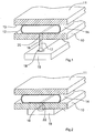
- eine schematische perspektivische Schnittdarstellung einer ersten Ausführungsform des Drucksensors mit einem Festkörpersteg, und
- Fig. 2
- gleiche Darstellung wie
Figur 1 einen Drucksensor mit einem inkompressiblen Gel.
- Fig. 1
- a schematic perspective sectional view of a first embodiment of the pressure sensor with a solid web, and
- Fig. 2
- same representation as
FIG. 1 a pressure sensor with an incompressible gel.
Der Drucksensor nach
Der Schlauch 14 besteht aus einem flexiblen Material, das elastisch ist und somit eine Rückstellfähigkeit hat. Der Querschnitt des Schlauchs 14 ist im unkomprimierten Zustand rund. Im flachgedrückten Zustand des Schlauchs hat der Schlauchquerschnitt eine längliche Form, so wie dies in
Durch den Stützkörper 10 erstreckt sich ein längslaufender Spalt 16, der im Mittelbereich des flachgedrückten Schlauchs 14 angeordnet ist. Der Schlauch 14 wird durch (nicht dargestellte) Seitenwände in einer definierten Position zwischen den Stützkörpern 10,11 gehalten. Der Spalt 16 erstreckt sich durch die Dicke des Stützkörpers 10 hindurch. In dem Spalt 16 ist ein Kraftübertragungsmittel in Form eines Steges 17 angeordnet. Der Steg 17 ist quer zu dem Stützkörper 10 verschiebbar. Er erstreckt sich in Längsrichtung des Schlauchs 14. An dem einen Ende des Steges 17 ist ein Fuß 18 vorgesehen, der gegen einen Kraftsensor 19 drückt. Der Kraftsensor 19 ist an dem Stützkörper 10 durch (nicht dargestellte) Zuhaltemittel starr befestigt. Der Kraftsensor 19 weist beispielsweise Dehnmessstreifen auf, die zu einer Brückenschaltung geschaltet sind und ein elektrisches Signal erzeugen, das der auf den Kraftsensor 19 einwirkenden Kraft F proportional ist.Through the
Ein entsprechender Kraftsensor 19 kann auch an dem gegenüberliegenden Ende des Steges 17 angeordnet sein, wo ein dem Fuß 18 entsprechender weiterer Fuß vorgesehen ist.A corresponding
Der Steg 17 ist ein Festkörper, der beispielsweise aus einer starren Platte besteht. Das obere Ende 20 des Steges 17 drückt unmittelbar gegen den Umfang des Schlauchs 14, und zwar im Mittelbereich des zwischen den Stützkörpern 10,11 flachgedrückten Schlauchs, wo die Schlauchwandung geradlinig verläuft.The
Bei dem Ausführungsbeispiel von
In beiden Fällen wird bei einer Druckänderung im Schlauch 14 nur die Schlauchverformung am Spalt 16 zur Erzeugung des Kraftsignals ausgewertet. Der Kraftsensor 19 erzeugt ein elektrisches Signal, welches dem Innendruck des Schlauchs mit hoher Genauigkeit proportional ist.In both cases, with a pressure change in the
Bei einem Ausführungsbeispiel der Erfindung entspricht ein Druck von 1 bar einer Kraft von 100.000 N/m2. Bei einer Fläche des Spalts von 10 mm x 2 mm ergeben sich 2 N/bar. Der Proportionalitätsfaktor beträgt hierbei 0,5.In one embodiment of the invention, a pressure of 1 bar corresponds to a force of 100,000 N / m 2 . With an area of the gap of 10 mm × 2 mm, this results in 2 N / bar. The proportionality factor is 0.5.
Claims (4)
- A pressure sensor comprising a hose (14) for passing a fluid, two supporting bodies (10,11) deforming the cross-section of the hose (14), and a force sensor (19) reacting to the internal pressure of the hose,
wherein at least one of the supporting bodies (10,11) includes a force transmission means which extends over less than 25% of the lumen of the hose deformed by the supporting bodies, and which is movable relative to this supporting body and presses against the hose (14) with one end and against the force sensor (19) with the other end,
wherein the supporting bodies (10, 11) are plate-shaped and each have a planar contact surface (12, 13),
characterized in that
the force transmission means is a web (17) extending in the longitudinal direction of the hose (14) and arranged in a gap (16) that extends in the longitudinal direction of the hose (14) and passes through the supporting body (10). - The pressure sensor according to claim 1, characterized in that the force sensor (19) has a maximum deflection of less than 1 mm.
- The pressure sensor according to claim 1 or 2, characterized in that the web (17) is formed by a rigid plate.
- A pressure sensor comprising a hose (14) for passing a fluid, two supporting bodies (10,11) deforming the cross-section of the hose (14), and a force sensor (19) reacting to the internal pressure of the hose,
wherein at least one of the supporting bodies (10,11) includes a force transmission means which extends over less than 25% of the lumen of the hose deformed by the supporting bodies, and which is movable relative to this supporting body and presses against the hose (14) with one end and against the force sensor (19) with the other end,
wherein the supporting bodies (10, 11) are plate-shaped without any lateral hose deforming walls and each have a planar contact surface (12, 13),
characterized in that
the force transmission means is an incompressible gel (22) extending in the longitudinal direction of the hose (14) and arranged in a gap (16) that extends in the longitudinal direction of the hose (14) and passes through the supporting body (10).
Applications Claiming Priority (2)
| Application Number | Priority Date | Filing Date | Title |
|---|---|---|---|
| DE20206474U DE20206474U1 (en) | 2002-04-24 | 2002-04-24 | Pressure sensor for infusion hose pumps |
| DE20206474U | 2002-04-24 |
Publications (2)
| Publication Number | Publication Date |
|---|---|
| EP1357372A1 EP1357372A1 (en) | 2003-10-29 |
| EP1357372B1 true EP1357372B1 (en) | 2014-01-08 |
Family
ID=27816268
Family Applications (1)
| Application Number | Title | Priority Date | Filing Date |
|---|---|---|---|
| EP03009109.4A Expired - Lifetime EP1357372B1 (en) | 2002-04-24 | 2003-04-19 | Pressure sensor |
Country Status (7)
| Country | Link |
|---|---|
| US (1) | US6889556B2 (en) |
| EP (1) | EP1357372B1 (en) |
| JP (1) | JP4394897B2 (en) |
| CN (1) | CN100427910C (en) |
| AU (1) | AU2003203822B2 (en) |
| CA (1) | CA2426418C (en) |
| DE (1) | DE20206474U1 (en) |
Cited By (1)
| Publication number | Priority date | Publication date | Assignee | Title |
|---|---|---|---|---|
| EP4174467A1 (en) | 2021-10-29 | 2023-05-03 | B. Braun Melsungen AG | Gel-coupled pressure sensor device with disturbance-independent contact side for connection to an infusion tube |
Families Citing this family (30)
| Publication number | Priority date | Publication date | Assignee | Title |
|---|---|---|---|---|
| JP2004361308A (en) * | 2003-06-06 | 2004-12-24 | Fuji Electric Device Technology Co Ltd | Physical quantity detector, and storage case for physical quantity detecting means |
| WO2005003713A2 (en) * | 2003-06-24 | 2005-01-13 | Cidra Corporation | Contact-based transducers for characterizing unsteady pressures in pipes |
| US7197938B2 (en) * | 2003-06-24 | 2007-04-03 | Cidra Corporation | Contact-based transducers for characterizing unsteady pressures in pipes |
| GB2417052B (en) * | 2004-08-12 | 2009-12-23 | Single Use Surgical Ltd | Pressure monitor for peristaltic pumps |
| DE102007000200A1 (en) * | 2007-04-03 | 2008-10-09 | Invendo Medical Gmbh | Pressure measuring device |
| US8083503B2 (en) | 2007-09-27 | 2011-12-27 | Curlin Medical Inc. | Peristaltic pump assembly and regulator therefor |
| US7934912B2 (en) | 2007-09-27 | 2011-05-03 | Curlin Medical Inc | Peristaltic pump assembly with cassette and mounting pin arrangement |
| US8062008B2 (en) | 2007-09-27 | 2011-11-22 | Curlin Medical Inc. | Peristaltic pump and removable cassette therefor |
| JP5237682B2 (en) * | 2007-09-28 | 2013-07-17 | 東レエンジニアリング株式会社 | Pressure measuring device |
| US8753515B2 (en) | 2009-12-05 | 2014-06-17 | Home Dialysis Plus, Ltd. | Dialysis system with ultrafiltration control |
| US8501009B2 (en) | 2010-06-07 | 2013-08-06 | State Of Oregon Acting By And Through The State Board Of Higher Education On Behalf Of Oregon State University | Fluid purification system |
| US8486020B2 (en) * | 2010-08-11 | 2013-07-16 | Zevex, Inc. | Pressure sensor and method of use |
| CN103260671B (en) * | 2010-10-01 | 2015-10-21 | 泽维克斯公司 | Pressure sensor seals and using method |
| EP2763719B1 (en) | 2011-10-07 | 2017-08-09 | Outset Medical, Inc. | Heat exchange fluid purification for dialysis system |
| US8946833B2 (en) * | 2012-10-22 | 2015-02-03 | Freescale Semiconductor, Inc. | Packaging for semiconductor sensor devices and methods |
| EP2922468B1 (en) * | 2013-02-13 | 2016-06-08 | Leman Micro Devices SA | Non-invasive blood analysis |
| WO2014150156A1 (en) | 2013-03-14 | 2014-09-25 | Trl Enterprises Llc | Fully swept pressure sensor |
| US9625333B2 (en) * | 2013-03-15 | 2017-04-18 | President And Fellows Of Harvard College | Tactile sensor |
| CN104155049B (en) * | 2013-05-15 | 2016-12-28 | 深圳市深科医疗器械技术开发有限公司 | Device for the detection of flexible pipe fluid pressure |
| EP2881130B1 (en) * | 2013-12-04 | 2018-06-06 | seiratherm GmbH | System for measuring pressure and temperature of a fluid and an apparatus for adjusting or stabilizing the temperature of a patient |
| ES2864727T3 (en) | 2014-04-29 | 2021-10-14 | Outset Medical Inc | Dialysis system and methods |
| CN105424268A (en) * | 2015-12-15 | 2016-03-23 | 深圳市深科医疗器械技术开发有限公司 | Pressure detection device for fluid in hose |
| US11534537B2 (en) | 2016-08-19 | 2022-12-27 | Outset Medical, Inc. | Peritoneal dialysis system and methods |
| DE102017121347A1 (en) | 2017-09-14 | 2019-03-14 | Turck Holding Gmbh | Hose pressure sensor for a peristaltic pump arrangement |
| US11191897B2 (en) | 2019-03-04 | 2021-12-07 | Eitan Medical Ltd. | In cycle pressure measurement |
| WO2020178827A1 (en) | 2019-03-05 | 2020-09-10 | Avoset Health Ltd. | Anti-free-flow valve |
| DE102019113561A1 (en) | 2019-05-21 | 2020-11-26 | B.Braun Avitum Ag | Pressure measurement in the extracorporeal blood circuit |
| DE102019130656A1 (en) | 2019-11-13 | 2021-05-20 | B.Braun Avitum Ag | Pressure measurement in the extracorporeal blood circuit |
| CN111289151B (en) * | 2020-02-25 | 2020-12-01 | 青岛大学附属医院 | Medical robot sensor |
| DE102020207084A1 (en) | 2020-06-05 | 2021-12-09 | B. Braun Melsungen Aktiengesellschaft | Infusion filter |
Citations (2)
| Publication number | Priority date | Publication date | Assignee | Title |
|---|---|---|---|---|
| DE3838689C1 (en) * | 1988-11-15 | 1990-06-28 | Fresenius Ag, 6380 Bad Homburg, De | Method for the continuous measurement of the pressure in a flexible fluid line for medical purposes, as well as a device for carrying out the method |
| DE29602065U1 (en) * | 1996-02-07 | 1997-03-06 | Wurster Helmut Dipl Ing | Indirect pressure measurement |
Family Cites Families (13)
| Publication number | Priority date | Publication date | Assignee | Title |
|---|---|---|---|---|
| US2783325A (en) * | 1955-01-17 | 1957-02-26 | John A Luckey | Extended length hydraulic switch |
| FR2391507A1 (en) * | 1977-05-17 | 1978-12-15 | Valansot Jean | SPATIAL EXTENSION MANUAL CONTROL DEVICE AND APPLICATIONS |
| JPS5631758A (en) * | 1979-08-24 | 1981-03-31 | Sharp Kk | Detector for clogging condition of flexible tube |
| IT8453709V0 (en) * | 1984-08-07 | 1984-08-07 | Hospal Dasco Spa | PERFECTED TYPE EQUIPMENT FOR THE CIRCULATION OF A LIQUID ALONG A TUBULAR LINE |
| JPH02203230A (en) * | 1989-01-31 | 1990-08-13 | Daikin Ind Ltd | Detector converter for variation in pressure in tube |
| DE3918534A1 (en) * | 1989-06-07 | 1990-12-20 | Braun Melsungen Ag | PRESSURE SENSOR FOR INFUSION PIPES |
| DE4013403C2 (en) * | 1990-04-26 | 1994-06-30 | Infurex Ag Cham | Device for detecting the internal pressure conditions in flexible lines |
| GB2247317B (en) * | 1990-08-13 | 1994-05-04 | Danby Medical Ltd | A device for monitoring pressure in a fluid flow system |
| EP0702213B1 (en) * | 1994-09-19 | 2003-09-24 | Endress + Hauser Flowtec AG | Fixation method of the conduits of a mass flow sensor |
| US6250164B1 (en) * | 1997-02-12 | 2001-06-26 | Medtronic, Inc. | Measurement of fluid pressure within a tube |
| US6047457A (en) * | 1997-03-17 | 2000-04-11 | Endress + Hauser Flowtec Ag | Method of fastening a metal body to a measuring tube of a coriolis-type mass flow sensor |
| CA2381456C (en) * | 2001-04-25 | 2011-08-02 | Oertli-Instrumente Ag | Pressure measuring system for measuring line pressure |
| DE10160864A1 (en) * | 2001-12-12 | 2003-06-26 | Hilti Ag | Axial striking electric hand tool device |
-
2002
- 2002-04-24 DE DE20206474U patent/DE20206474U1/en not_active Expired - Lifetime
-
2003
- 2003-04-19 EP EP03009109.4A patent/EP1357372B1/en not_active Expired - Lifetime
- 2003-04-23 AU AU2003203822A patent/AU2003203822B2/en not_active Ceased
- 2003-04-23 US US10/421,145 patent/US6889556B2/en not_active Expired - Lifetime
- 2003-04-23 CA CA2426418A patent/CA2426418C/en not_active Expired - Lifetime
- 2003-04-23 JP JP2003118307A patent/JP4394897B2/en not_active Expired - Lifetime
- 2003-04-24 CN CNB031224369A patent/CN100427910C/en not_active Expired - Fee Related
Patent Citations (2)
| Publication number | Priority date | Publication date | Assignee | Title |
|---|---|---|---|---|
| DE3838689C1 (en) * | 1988-11-15 | 1990-06-28 | Fresenius Ag, 6380 Bad Homburg, De | Method for the continuous measurement of the pressure in a flexible fluid line for medical purposes, as well as a device for carrying out the method |
| DE29602065U1 (en) * | 1996-02-07 | 1997-03-06 | Wurster Helmut Dipl Ing | Indirect pressure measurement |
Cited By (2)
| Publication number | Priority date | Publication date | Assignee | Title |
|---|---|---|---|---|
| EP4174467A1 (en) | 2021-10-29 | 2023-05-03 | B. Braun Melsungen AG | Gel-coupled pressure sensor device with disturbance-independent contact side for connection to an infusion tube |
| DE102021128378A1 (en) | 2021-10-29 | 2023-05-04 | B. Braun Melsungen Aktiengesellschaft | Gel-coupled pressure sensor device with an interference-independent contact side for connection to an infusion tube |
Also Published As
| Publication number | Publication date |
|---|---|
| US20030217602A1 (en) | 2003-11-27 |
| CA2426418A1 (en) | 2003-10-24 |
| AU2003203822A1 (en) | 2003-11-13 |
| JP2003322578A (en) | 2003-11-14 |
| JP4394897B2 (en) | 2010-01-06 |
| AU2003203822B2 (en) | 2007-10-04 |
| EP1357372A1 (en) | 2003-10-29 |
| CA2426418C (en) | 2012-01-03 |
| DE20206474U1 (en) | 2003-09-04 |
| US6889556B2 (en) | 2005-05-10 |
| CN100427910C (en) | 2008-10-22 |
| CN1453565A (en) | 2003-11-05 |
Similar Documents
| Publication | Publication Date | Title |
|---|---|---|
| EP1357372B1 (en) | Pressure sensor | |
| EP0388596B1 (en) | Pump tube for a peristaltic pump | |
| EP2659248B1 (en) | Pressure sensor having a compressible element | |
| DE2633379B2 (en) | Device for measuring the geometry of the mold cavity of continuous casting molds | |
| WO2010006898A1 (en) | Chemical seal and pressure measuring device having such a seal | |
| EP1169202B1 (en) | Device for measuring the pressure of a fluid | |
| EP2981796A1 (en) | Force-measuring device | |
| DE3838689C1 (en) | Method for the continuous measurement of the pressure in a flexible fluid line for medical purposes, as well as a device for carrying out the method | |
| WO2012089626A2 (en) | Pressure sensor having a compressible element | |
| DE3918142C2 (en) | ||
| DE2117477B2 (en) | Force transducer | |
| DE2445835C2 (en) | Measuring gauge, in particular for measuring the inside diameter of bores | |
| DE1473689A1 (en) | Electrical pressure transducer | |
| DE3103163A1 (en) | MEASURING DEVICE FOR DETERMINING THE STRENGTH OF TISSUES | |
| EP1537393B1 (en) | Device for showing tensile stress | |
| EP2402729A1 (en) | Torque measurement device | |
| DE2145198C3 (en) | Pressure receptor | |
| EP3191236B1 (en) | Press brake and a method for bending a workpiece with the bending press | |
| DE2607647A1 (en) | LIQUID LEVEL TRANSDUCER | |
| CH649012A5 (en) | MEASURING DEVICE FOR DETECTING THE GAP OF A WORKING ROLLER PAIR. | |
| DE2827061C3 (en) | Load cell | |
| EP0077318A2 (en) | Arrangement for measuring two oppositely arranged roller-ways of a continuous-casting machine | |
| EP2674105B1 (en) | Dispositif de détection utilisable en intra-oral | |
| DE2429692C3 (en) | Measuring device for determining the excess length and inclination of the abutting surfaces of two-part plain bearing shells | |
| DE1901434A1 (en) | Differential pressure measuring device |
Legal Events
| Date | Code | Title | Description |
|---|---|---|---|
| PUAI | Public reference made under article 153(3) epc to a published international application that has entered the european phase |
Free format text: ORIGINAL CODE: 0009012 |
|
| AK | Designated contracting states |
Kind code of ref document: A1 Designated state(s): AT BE BG CH CY CZ DE DK EE ES FI FR GB GR HU IE IT LI LU MC NL PT RO SE SI SK TR |
|
| AX | Request for extension of the european patent |
Extension state: AL LT LV MK |
|
| 17P | Request for examination filed |
Effective date: 20040416 |
|
| AKX | Designation fees paid |
Designated state(s): DE ES FR GB IT |
|
| 17Q | First examination report despatched |
Effective date: 20051104 |
|
| 17Q | First examination report despatched |
Effective date: 20051104 |
|
| APBK | Appeal reference recorded |
Free format text: ORIGINAL CODE: EPIDOSNREFNE |
|
| APBN | Date of receipt of notice of appeal recorded |
Free format text: ORIGINAL CODE: EPIDOSNNOA2E |
|
| APBR | Date of receipt of statement of grounds of appeal recorded |
Free format text: ORIGINAL CODE: EPIDOSNNOA3E |
|
| APAF | Appeal reference modified |
Free format text: ORIGINAL CODE: EPIDOSCREFNE |
|
| APBT | Appeal procedure closed |
Free format text: ORIGINAL CODE: EPIDOSNNOA9E |
|
| REG | Reference to a national code |
Ref country code: DE Ref legal event code: R079 Ref document number: 50314971 Country of ref document: DE Free format text: PREVIOUS MAIN CLASS: G01L0009000000 Ipc: A61M0001360000 |
|
| RIC1 | Information provided on ipc code assigned before grant |
Ipc: G01L 9/00 20060101ALI20130529BHEP Ipc: A61M 1/36 20060101AFI20130529BHEP Ipc: A61M 5/168 20060101ALI20130529BHEP |
|
| GRAP | Despatch of communication of intention to grant a patent |
Free format text: ORIGINAL CODE: EPIDOSNIGR1 |
|
| INTG | Intention to grant announced |
Effective date: 20130726 |
|
| GRAS | Grant fee paid |
Free format text: ORIGINAL CODE: EPIDOSNIGR3 |
|
| GRAA | (expected) grant |
Free format text: ORIGINAL CODE: 0009210 |
|
| AK | Designated contracting states |
Kind code of ref document: B1 Designated state(s): DE ES FR GB IT |
|
| REG | Reference to a national code |
Ref country code: GB Ref legal event code: FG4D Free format text: NOT ENGLISH |
|
| REG | Reference to a national code |
Ref country code: DE Ref legal event code: R096 Ref document number: 50314971 Country of ref document: DE Effective date: 20140220 |
|
| PG25 | Lapsed in a contracting state [announced via postgrant information from national office to epo] |
Ref country code: ES Free format text: LAPSE BECAUSE OF FAILURE TO SUBMIT A TRANSLATION OF THE DESCRIPTION OR TO PAY THE FEE WITHIN THE PRESCRIBED TIME-LIMIT Effective date: 20140108 |
|
| REG | Reference to a national code |
Ref country code: DE Ref legal event code: R097 Ref document number: 50314971 Country of ref document: DE |
|
| PLBE | No opposition filed within time limit |
Free format text: ORIGINAL CODE: 0009261 |
|
| STAA | Information on the status of an ep patent application or granted ep patent |
Free format text: STATUS: NO OPPOSITION FILED WITHIN TIME LIMIT |
|
| 26N | No opposition filed |
Effective date: 20141009 |
|
| REG | Reference to a national code |
Ref country code: DE Ref legal event code: R097 Ref document number: 50314971 Country of ref document: DE Effective date: 20141009 |
|
| PGFP | Annual fee paid to national office [announced via postgrant information from national office to epo] |
Ref country code: IT Payment date: 20150427 Year of fee payment: 13 |
|
| REG | Reference to a national code |
Ref country code: FR Ref legal event code: PLFP Year of fee payment: 14 |
|
| PG25 | Lapsed in a contracting state [announced via postgrant information from national office to epo] |
Ref country code: IT Free format text: LAPSE BECAUSE OF NON-PAYMENT OF DUE FEES Effective date: 20160419 |
|
| REG | Reference to a national code |
Ref country code: FR Ref legal event code: PLFP Year of fee payment: 15 |
|
| REG | Reference to a national code |
Ref country code: FR Ref legal event code: PLFP Year of fee payment: 16 |
|
| PGFP | Annual fee paid to national office [announced via postgrant information from national office to epo] |
Ref country code: GB Payment date: 20220425 Year of fee payment: 20 Ref country code: FR Payment date: 20220420 Year of fee payment: 20 Ref country code: DE Payment date: 20220419 Year of fee payment: 20 |
|
| REG | Reference to a national code |
Ref country code: DE Ref legal event code: R071 Ref document number: 50314971 Country of ref document: DE |
|
| REG | Reference to a national code |
Ref country code: GB Ref legal event code: PE20 Expiry date: 20230418 |
|
| PG25 | Lapsed in a contracting state [announced via postgrant information from national office to epo] |
Ref country code: GB Free format text: LAPSE BECAUSE OF EXPIRATION OF PROTECTION Effective date: 20230418 |