EP1359634A2 - Composite membrane - Google Patents
Composite membrane Download PDFInfo
- Publication number
- EP1359634A2 EP1359634A2 EP03252423A EP03252423A EP1359634A2 EP 1359634 A2 EP1359634 A2 EP 1359634A2 EP 03252423 A EP03252423 A EP 03252423A EP 03252423 A EP03252423 A EP 03252423A EP 1359634 A2 EP1359634 A2 EP 1359634A2
- Authority
- EP
- European Patent Office
- Prior art keywords
- membrane
- fibres
- composite membrane
- composite
- continuous region
- Prior art date
- Legal status (The legal status is an assumption and is not a legal conclusion. Google has not performed a legal analysis and makes no representation as to the accuracy of the status listed.)
- Granted
Links
- 239000012528 membrane Substances 0.000 title claims abstract description 268
- 239000002131 composite material Substances 0.000 title claims abstract description 80
- 238000000034 method Methods 0.000 claims abstract description 38
- 230000008569 process Effects 0.000 claims abstract description 32
- 239000002322 conducting polymer Substances 0.000 claims abstract description 28
- 229920001940 conductive polymer Polymers 0.000 claims abstract description 28
- 238000004519 manufacturing process Methods 0.000 claims abstract description 13
- 229920000642 polymer Polymers 0.000 claims description 55
- 239000000835 fiber Substances 0.000 claims description 35
- 239000008199 coating composition Substances 0.000 claims description 28
- 239000000463 material Substances 0.000 claims description 25
- 239000000243 solution Substances 0.000 claims description 22
- VYPSYNLAJGMNEJ-UHFFFAOYSA-N Silicium dioxide Chemical compound O=[Si]=O VYPSYNLAJGMNEJ-UHFFFAOYSA-N 0.000 claims description 13
- 239000000203 mixture Substances 0.000 claims description 8
- 239000000155 melt Substances 0.000 claims description 6
- 238000001125 extrusion Methods 0.000 claims description 2
- 238000001746 injection moulding Methods 0.000 claims description 2
- 230000000712 assembly Effects 0.000 abstract description 2
- 238000000429 assembly Methods 0.000 abstract description 2
- 230000000052 comparative effect Effects 0.000 description 37
- 239000007789 gas Substances 0.000 description 33
- 229920003935 Flemion® Polymers 0.000 description 25
- 239000000446 fuel Substances 0.000 description 10
- 239000000376 reactant Substances 0.000 description 10
- OKKJLVBELUTLKV-UHFFFAOYSA-N Methanol Chemical compound OC OKKJLVBELUTLKV-UHFFFAOYSA-N 0.000 description 9
- 238000005259 measurement Methods 0.000 description 8
- 239000003054 catalyst Substances 0.000 description 7
- BASFCYQUMIYNBI-UHFFFAOYSA-N platinum Chemical compound [Pt] BASFCYQUMIYNBI-UHFFFAOYSA-N 0.000 description 7
- 239000007787 solid Substances 0.000 description 7
- XLYOFNOQVPJJNP-UHFFFAOYSA-N water Substances O XLYOFNOQVPJJNP-UHFFFAOYSA-N 0.000 description 7
- 238000005266 casting Methods 0.000 description 6
- 238000007755 gap coating Methods 0.000 description 6
- 239000007800 oxidant agent Substances 0.000 description 6
- 230000001590 oxidative effect Effects 0.000 description 6
- 239000000758 substrate Substances 0.000 description 6
- 238000000576 coating method Methods 0.000 description 5
- 230000036571 hydration Effects 0.000 description 5
- 238000006703 hydration reaction Methods 0.000 description 5
- 239000001257 hydrogen Substances 0.000 description 5
- 229910052739 hydrogen Inorganic materials 0.000 description 5
- BDHFUVZGWQCTTF-UHFFFAOYSA-N sulfonic acid Chemical class OS(=O)=O BDHFUVZGWQCTTF-UHFFFAOYSA-N 0.000 description 5
- UFHFLCQGNIYNRP-UHFFFAOYSA-N Hydrogen Chemical compound [H][H] UFHFLCQGNIYNRP-UHFFFAOYSA-N 0.000 description 4
- PPBRXRYQALVLMV-UHFFFAOYSA-N Styrene Chemical compound C=CC1=CC=CC=C1 PPBRXRYQALVLMV-UHFFFAOYSA-N 0.000 description 4
- 239000003570 air Substances 0.000 description 4
- QVGXLLKOCUKJST-UHFFFAOYSA-N atomic oxygen Chemical compound [O] QVGXLLKOCUKJST-UHFFFAOYSA-N 0.000 description 4
- 239000008367 deionised water Substances 0.000 description 4
- 238000009792 diffusion process Methods 0.000 description 4
- 239000010411 electrocatalyst Substances 0.000 description 4
- 239000003792 electrolyte Substances 0.000 description 4
- 238000005342 ion exchange Methods 0.000 description 4
- 229920000554 ionomer Polymers 0.000 description 4
- 239000001301 oxygen Substances 0.000 description 4
- 229910052760 oxygen Inorganic materials 0.000 description 4
- -1 styrene-(ethylene-butylene)-styrene Chemical class 0.000 description 4
- 239000000126 substance Substances 0.000 description 4
- 229920000557 Nafion® Polymers 0.000 description 3
- HEMHJVSKTPXQMS-UHFFFAOYSA-M Sodium hydroxide Chemical compound [OH-].[Na+] HEMHJVSKTPXQMS-UHFFFAOYSA-M 0.000 description 3
- 230000002378 acidificating effect Effects 0.000 description 3
- 125000003118 aryl group Chemical group 0.000 description 3
- 238000006243 chemical reaction Methods 0.000 description 3
- 239000011248 coating agent Substances 0.000 description 3
- 239000011521 glass Substances 0.000 description 3
- 229910052697 platinum Inorganic materials 0.000 description 3
- 239000000377 silicon dioxide Substances 0.000 description 3
- 238000005507 spraying Methods 0.000 description 3
- 229920003934 Aciplex® Polymers 0.000 description 2
- 208000025165 Autoerythrocyte sensitization syndrome Diseases 0.000 description 2
- OKTJSMMVPCPJKN-UHFFFAOYSA-N Carbon Chemical group [C] OKTJSMMVPCPJKN-UHFFFAOYSA-N 0.000 description 2
- 239000004812 Fluorinated ethylene propylene Substances 0.000 description 2
- 229910018828 PO3H2 Inorganic materials 0.000 description 2
- NBIIXXVUZAFLBC-UHFFFAOYSA-N Phosphoric acid Chemical compound OP(O)(O)=O NBIIXXVUZAFLBC-UHFFFAOYSA-N 0.000 description 2
- 238000003853 Pinholing Methods 0.000 description 2
- 239000004693 Polybenzimidazole Substances 0.000 description 2
- QAOWNCQODCNURD-UHFFFAOYSA-N Sulfuric acid Chemical compound OS(O)(=O)=O QAOWNCQODCNURD-UHFFFAOYSA-N 0.000 description 2
- 238000005349 anion exchange Methods 0.000 description 2
- 239000006229 carbon black Substances 0.000 description 2
- 125000002843 carboxylic acid group Chemical group 0.000 description 2
- 230000008859 change Effects 0.000 description 2
- 229920001577 copolymer Polymers 0.000 description 2
- 125000004122 cyclic group Chemical group 0.000 description 2
- 239000002019 doping agent Substances 0.000 description 2
- 229920002313 fluoropolymer Polymers 0.000 description 2
- 239000003014 ion exchange membrane Substances 0.000 description 2
- 150000002500 ions Chemical class 0.000 description 2
- 238000003475 lamination Methods 0.000 description 2
- 239000007788 liquid Substances 0.000 description 2
- 229920009441 perflouroethylene propylene Polymers 0.000 description 2
- ABLZXFCXXLZCGV-UHFFFAOYSA-N phosphonic acid group Chemical group P(O)(O)=O ABLZXFCXXLZCGV-UHFFFAOYSA-N 0.000 description 2
- 229920002480 polybenzimidazole Polymers 0.000 description 2
- 229920002620 polyvinyl fluoride Polymers 0.000 description 2
- 229920002981 polyvinylidene fluoride Polymers 0.000 description 2
- 239000002243 precursor Substances 0.000 description 2
- 238000007639 printing Methods 0.000 description 2
- 239000010453 quartz Substances 0.000 description 2
- 125000001453 quaternary ammonium group Chemical group 0.000 description 2
- 230000005855 radiation Effects 0.000 description 2
- 230000002787 reinforcement Effects 0.000 description 2
- 229910052707 ruthenium Inorganic materials 0.000 description 2
- YBBRCQOCSYXUOC-UHFFFAOYSA-N sulfuryl dichloride Chemical group ClS(Cl)(=O)=O YBBRCQOCSYXUOC-UHFFFAOYSA-N 0.000 description 2
- OBTWBSRJZRCYQV-UHFFFAOYSA-N sulfuryl difluoride Chemical compound FS(F)(=O)=O OBTWBSRJZRCYQV-UHFFFAOYSA-N 0.000 description 2
- BQCIDUSAKPWEOX-UHFFFAOYSA-N 1,1-Difluoroethene Chemical compound FC(F)=C BQCIDUSAKPWEOX-UHFFFAOYSA-N 0.000 description 1
- QSIFOTQDNVCTTM-UHFFFAOYSA-N 3-methyl-1h-imidazol-3-ium;trifluoromethanesulfonate Chemical compound CN1C=CN=C1.OS(=O)(=O)C(F)(F)F QSIFOTQDNVCTTM-UHFFFAOYSA-N 0.000 description 1
- 229920013683 Celanese Polymers 0.000 description 1
- 241001633942 Dais Species 0.000 description 1
- 239000005977 Ethylene Substances 0.000 description 1
- 229910004727 OSO3H Inorganic materials 0.000 description 1
- 229920001774 Perfluoroether Polymers 0.000 description 1
- 239000004721 Polyphenylene oxide Substances 0.000 description 1
- 229910001260 Pt alloy Inorganic materials 0.000 description 1
- 229910000929 Ru alloy Inorganic materials 0.000 description 1
- KJTLSVCANCCWHF-UHFFFAOYSA-N Ruthenium Chemical compound [Ru] KJTLSVCANCCWHF-UHFFFAOYSA-N 0.000 description 1
- 229910006069 SO3H Inorganic materials 0.000 description 1
- XECAHXYUAAWDEL-UHFFFAOYSA-N acrylonitrile butadiene styrene Chemical compound C=CC=C.C=CC#N.C=CC1=CC=CC=C1 XECAHXYUAAWDEL-UHFFFAOYSA-N 0.000 description 1
- 229920000122 acrylonitrile butadiene styrene Polymers 0.000 description 1
- 239000004676 acrylonitrile butadiene styrene Substances 0.000 description 1
- 125000000217 alkyl group Chemical group 0.000 description 1
- 229910000147 aluminium phosphate Inorganic materials 0.000 description 1
- 239000012080 ambient air Substances 0.000 description 1
- 239000003011 anion exchange membrane Substances 0.000 description 1
- 238000013459 approach Methods 0.000 description 1
- JXLHNMVSKXFWAO-UHFFFAOYSA-N azane;7-fluoro-2,1,3-benzoxadiazole-4-sulfonic acid Chemical compound N.OS(=O)(=O)C1=CC=C(F)C2=NON=C12 JXLHNMVSKXFWAO-UHFFFAOYSA-N 0.000 description 1
- 230000008901 benefit Effects 0.000 description 1
- 239000011230 binding agent Substances 0.000 description 1
- 229910052799 carbon Inorganic materials 0.000 description 1
- 239000000919 ceramic Substances 0.000 description 1
- 239000003795 chemical substances by application Substances 0.000 description 1
- 238000002485 combustion reaction Methods 0.000 description 1
- 239000004020 conductor Substances 0.000 description 1
- 238000007796 conventional method Methods 0.000 description 1
- 230000003247 decreasing effect Effects 0.000 description 1
- 230000001419 dependent effect Effects 0.000 description 1
- 238000007607 die coating method Methods 0.000 description 1
- 239000006185 dispersion Substances 0.000 description 1
- 238000006073 displacement reaction Methods 0.000 description 1
- 238000007606 doctor blade method Methods 0.000 description 1
- 230000000694 effects Effects 0.000 description 1
- 238000003487 electrochemical reaction Methods 0.000 description 1
- 238000003411 electrode reaction Methods 0.000 description 1
- 238000005516 engineering process Methods 0.000 description 1
- 239000010408 film Substances 0.000 description 1
- UQSQSQZYBQSBJZ-UHFFFAOYSA-N fluorosulfonic acid Chemical compound OS(F)(=O)=O UQSQSQZYBQSBJZ-UHFFFAOYSA-N 0.000 description 1
- 238000007731 hot pressing Methods 0.000 description 1
- 229930195733 hydrocarbon Natural products 0.000 description 1
- 150000002430 hydrocarbons Chemical class 0.000 description 1
- 150000002431 hydrogen Chemical class 0.000 description 1
- 230000007062 hydrolysis Effects 0.000 description 1
- 238000006460 hydrolysis reaction Methods 0.000 description 1
- 238000011065 in-situ storage Methods 0.000 description 1
- 230000000977 initiatory effect Effects 0.000 description 1
- 238000009685 knife-over-roll coating Methods 0.000 description 1
- 239000011244 liquid electrolyte Substances 0.000 description 1
- QLOAVXSYZAJECW-UHFFFAOYSA-N methane;molecular fluorine Chemical group C.FF QLOAVXSYZAJECW-UHFFFAOYSA-N 0.000 description 1
- 230000004048 modification Effects 0.000 description 1
- 238000012986 modification Methods 0.000 description 1
- 125000000896 monocarboxylic acid group Chemical group 0.000 description 1
- 239000000178 monomer Substances 0.000 description 1
- 125000004108 n-butyl group Chemical group [H]C([H])([H])C([H])([H])C([H])([H])C([H])([H])* 0.000 description 1
- QJGQUHMNIGDVPM-UHFFFAOYSA-N nitrogen group Chemical group [N] QJGQUHMNIGDVPM-UHFFFAOYSA-N 0.000 description 1
- 229920006120 non-fluorinated polymer Polymers 0.000 description 1
- 230000003287 optical effect Effects 0.000 description 1
- 230000037361 pathway Effects 0.000 description 1
- 230000035699 permeability Effects 0.000 description 1
- 229920006260 polyaryletherketone Polymers 0.000 description 1
- 229920000570 polyether Polymers 0.000 description 1
- 239000002861 polymer material Substances 0.000 description 1
- 229920005597 polymer membrane Polymers 0.000 description 1
- 239000004810 polytetrafluoroethylene Substances 0.000 description 1
- 229920001343 polytetrafluoroethylene Polymers 0.000 description 1
- 239000011148 porous material Substances 0.000 description 1
- 238000010248 power generation Methods 0.000 description 1
- 230000002035 prolonged effect Effects 0.000 description 1
- 238000005215 recombination Methods 0.000 description 1
- 230000006798 recombination Effects 0.000 description 1
- 238000009877 rendering Methods 0.000 description 1
- 238000005096 rolling process Methods 0.000 description 1
- 238000007650 screen-printing Methods 0.000 description 1
- 239000007784 solid electrolyte Substances 0.000 description 1
- 125000000020 sulfo group Chemical group O=S(=O)([*])O[H] 0.000 description 1
- 125000001174 sulfone group Chemical group 0.000 description 1
- 230000002459 sustained effect Effects 0.000 description 1
- 229920001897 terpolymer Polymers 0.000 description 1
- 125000005207 tetraalkylammonium group Chemical group 0.000 description 1
- 229920001169 thermoplastic Polymers 0.000 description 1
- 229920001187 thermosetting polymer Polymers 0.000 description 1
- 239000004416 thermosoftening plastic Substances 0.000 description 1
- 239000010409 thin film Substances 0.000 description 1
- 238000012546 transfer Methods 0.000 description 1
Images
Classifications
-
- C—CHEMISTRY; METALLURGY
- C08—ORGANIC MACROMOLECULAR COMPOUNDS; THEIR PREPARATION OR CHEMICAL WORKING-UP; COMPOSITIONS BASED THEREON
- C08J—WORKING-UP; GENERAL PROCESSES OF COMPOUNDING; AFTER-TREATMENT NOT COVERED BY SUBCLASSES C08B, C08C, C08F, C08G or C08H
- C08J5/00—Manufacture of articles or shaped materials containing macromolecular substances
- C08J5/20—Manufacture of shaped structures of ion-exchange resins
- C08J5/22—Films, membranes or diaphragms
- C08J5/2206—Films, membranes or diaphragms based on organic and/or inorganic macromolecular compounds
-
- B—PERFORMING OPERATIONS; TRANSPORTING
- B01—PHYSICAL OR CHEMICAL PROCESSES OR APPARATUS IN GENERAL
- B01D—SEPARATION
- B01D69/00—Semi-permeable membranes for separation processes or apparatus characterised by their form, structure or properties; Manufacturing processes specially adapted therefor
- B01D69/12—Composite membranes; Ultra-thin membranes
- B01D69/1212—Coextruded layers
-
- B—PERFORMING OPERATIONS; TRANSPORTING
- B01—PHYSICAL OR CHEMICAL PROCESSES OR APPARATUS IN GENERAL
- B01D—SEPARATION
- B01D69/00—Semi-permeable membranes for separation processes or apparatus characterised by their form, structure or properties; Manufacturing processes specially adapted therefor
- B01D69/12—Composite membranes; Ultra-thin membranes
- B01D69/1216—Three or more layers
-
- B—PERFORMING OPERATIONS; TRANSPORTING
- B01—PHYSICAL OR CHEMICAL PROCESSES OR APPARATUS IN GENERAL
- B01D—SEPARATION
- B01D69/00—Semi-permeable membranes for separation processes or apparatus characterised by their form, structure or properties; Manufacturing processes specially adapted therefor
- B01D69/14—Dynamic membranes
- B01D69/141—Heterogeneous membranes, e.g. containing dispersed material; Mixed matrix membranes
- B01D69/1411—Heterogeneous membranes, e.g. containing dispersed material; Mixed matrix membranes containing dispersed material in a continuous matrix
-
- B01J35/59—
-
- H—ELECTRICITY
- H01—ELECTRIC ELEMENTS
- H01B—CABLES; CONDUCTORS; INSULATORS; SELECTION OF MATERIALS FOR THEIR CONDUCTIVE, INSULATING OR DIELECTRIC PROPERTIES
- H01B1/00—Conductors or conductive bodies characterised by the conductive materials; Selection of materials as conductors
- H01B1/06—Conductors or conductive bodies characterised by the conductive materials; Selection of materials as conductors mainly consisting of other non-metallic substances
- H01B1/12—Conductors or conductive bodies characterised by the conductive materials; Selection of materials as conductors mainly consisting of other non-metallic substances organic substances
- H01B1/122—Ionic conductors
-
- H—ELECTRICITY
- H01—ELECTRIC ELEMENTS
- H01M—PROCESSES OR MEANS, e.g. BATTERIES, FOR THE DIRECT CONVERSION OF CHEMICAL ENERGY INTO ELECTRICAL ENERGY
- H01M8/00—Fuel cells; Manufacture thereof
- H01M8/10—Fuel cells with solid electrolytes
- H01M8/1007—Fuel cells with solid electrolytes with both reactants being gaseous or vaporised
-
- H—ELECTRICITY
- H01—ELECTRIC ELEMENTS
- H01M—PROCESSES OR MEANS, e.g. BATTERIES, FOR THE DIRECT CONVERSION OF CHEMICAL ENERGY INTO ELECTRICAL ENERGY
- H01M8/00—Fuel cells; Manufacture thereof
- H01M8/10—Fuel cells with solid electrolytes
- H01M8/1016—Fuel cells with solid electrolytes characterised by the electrolyte material
- H01M8/1018—Polymeric electrolyte materials
- H01M8/102—Polymeric electrolyte materials characterised by the chemical structure of the main chain of the ion-conducting polymer
- H01M8/1023—Polymeric electrolyte materials characterised by the chemical structure of the main chain of the ion-conducting polymer having only carbon, e.g. polyarylenes, polystyrenes or polybutadiene-styrenes
-
- H—ELECTRICITY
- H01—ELECTRIC ELEMENTS
- H01M—PROCESSES OR MEANS, e.g. BATTERIES, FOR THE DIRECT CONVERSION OF CHEMICAL ENERGY INTO ELECTRICAL ENERGY
- H01M8/00—Fuel cells; Manufacture thereof
- H01M8/10—Fuel cells with solid electrolytes
- H01M8/1016—Fuel cells with solid electrolytes characterised by the electrolyte material
- H01M8/1018—Polymeric electrolyte materials
- H01M8/1039—Polymeric electrolyte materials halogenated, e.g. sulfonated polyvinylidene fluorides
-
- H—ELECTRICITY
- H01—ELECTRIC ELEMENTS
- H01M—PROCESSES OR MEANS, e.g. BATTERIES, FOR THE DIRECT CONVERSION OF CHEMICAL ENERGY INTO ELECTRICAL ENERGY
- H01M8/00—Fuel cells; Manufacture thereof
- H01M8/10—Fuel cells with solid electrolytes
- H01M8/1016—Fuel cells with solid electrolytes characterised by the electrolyte material
- H01M8/1018—Polymeric electrolyte materials
- H01M8/1041—Polymer electrolyte composites, mixtures or blends
- H01M8/1053—Polymer electrolyte composites, mixtures or blends consisting of layers of polymers with at least one layer being ionically conductive
-
- C—CHEMISTRY; METALLURGY
- C08—ORGANIC MACROMOLECULAR COMPOUNDS; THEIR PREPARATION OR CHEMICAL WORKING-UP; COMPOSITIONS BASED THEREON
- C08J—WORKING-UP; GENERAL PROCESSES OF COMPOUNDING; AFTER-TREATMENT NOT COVERED BY SUBCLASSES C08B, C08C, C08F, C08G or C08H
- C08J2383/00—Characterised by the use of macromolecular compounds obtained by reactions forming in the main chain of the macromolecule a linkage containing silicon with or without sulfur, nitrogen, oxygen, or carbon only; Derivatives of such polymers
- C08J2383/02—Polysilicates
-
- H—ELECTRICITY
- H01—ELECTRIC ELEMENTS
- H01M—PROCESSES OR MEANS, e.g. BATTERIES, FOR THE DIRECT CONVERSION OF CHEMICAL ENERGY INTO ELECTRICAL ENERGY
- H01M2300/00—Electrolytes
- H01M2300/0017—Non-aqueous electrolytes
- H01M2300/0065—Solid electrolytes
- H01M2300/0082—Organic polymers
-
- H—ELECTRICITY
- H01—ELECTRIC ELEMENTS
- H01M—PROCESSES OR MEANS, e.g. BATTERIES, FOR THE DIRECT CONVERSION OF CHEMICAL ENERGY INTO ELECTRICAL ENERGY
- H01M2300/00—Electrolytes
- H01M2300/0088—Composites
- H01M2300/0094—Composites in the form of layered products, e.g. coatings
-
- H—ELECTRICITY
- H01—ELECTRIC ELEMENTS
- H01M—PROCESSES OR MEANS, e.g. BATTERIES, FOR THE DIRECT CONVERSION OF CHEMICAL ENERGY INTO ELECTRICAL ENERGY
- H01M8/00—Fuel cells; Manufacture thereof
- H01M8/10—Fuel cells with solid electrolytes
- H01M8/1016—Fuel cells with solid electrolytes characterised by the electrolyte material
- H01M8/1018—Polymeric electrolyte materials
- H01M8/1041—Polymer electrolyte composites, mixtures or blends
- H01M8/1046—Mixtures of at least one polymer and at least one additive
- H01M8/1051—Non-ion-conducting additives, e.g. stabilisers, SiO2 or ZrO2
-
- H—ELECTRICITY
- H01—ELECTRIC ELEMENTS
- H01M—PROCESSES OR MEANS, e.g. BATTERIES, FOR THE DIRECT CONVERSION OF CHEMICAL ENERGY INTO ELECTRICAL ENERGY
- H01M8/00—Fuel cells; Manufacture thereof
- H01M8/10—Fuel cells with solid electrolytes
- H01M8/1016—Fuel cells with solid electrolytes characterised by the electrolyte material
- H01M8/1018—Polymeric electrolyte materials
- H01M8/1069—Polymeric electrolyte materials characterised by the manufacturing processes
- H01M8/1081—Polymeric electrolyte materials characterised by the manufacturing processes starting from solutions, dispersions or slurries exclusively of polymers
-
- H—ELECTRICITY
- H01—ELECTRIC ELEMENTS
- H01M—PROCESSES OR MEANS, e.g. BATTERIES, FOR THE DIRECT CONVERSION OF CHEMICAL ENERGY INTO ELECTRICAL ENERGY
- H01M8/00—Fuel cells; Manufacture thereof
- H01M8/10—Fuel cells with solid electrolytes
- H01M8/1016—Fuel cells with solid electrolytes characterised by the electrolyte material
- H01M8/1018—Polymeric electrolyte materials
- H01M8/1069—Polymeric electrolyte materials characterised by the manufacturing processes
- H01M8/1083—Starting from polymer melts other than monomer melts
-
- Y—GENERAL TAGGING OF NEW TECHNOLOGICAL DEVELOPMENTS; GENERAL TAGGING OF CROSS-SECTIONAL TECHNOLOGIES SPANNING OVER SEVERAL SECTIONS OF THE IPC; TECHNICAL SUBJECTS COVERED BY FORMER USPC CROSS-REFERENCE ART COLLECTIONS [XRACs] AND DIGESTS
- Y02—TECHNOLOGIES OR APPLICATIONS FOR MITIGATION OR ADAPTATION AGAINST CLIMATE CHANGE
- Y02E—REDUCTION OF GREENHOUSE GAS [GHG] EMISSIONS, RELATED TO ENERGY GENERATION, TRANSMISSION OR DISTRIBUTION
- Y02E60/00—Enabling technologies; Technologies with a potential or indirect contribution to GHG emissions mitigation
- Y02E60/30—Hydrogen technology
- Y02E60/50—Fuel cells
-
- Y—GENERAL TAGGING OF NEW TECHNOLOGICAL DEVELOPMENTS; GENERAL TAGGING OF CROSS-SECTIONAL TECHNOLOGIES SPANNING OVER SEVERAL SECTIONS OF THE IPC; TECHNICAL SUBJECTS COVERED BY FORMER USPC CROSS-REFERENCE ART COLLECTIONS [XRACs] AND DIGESTS
- Y02—TECHNOLOGIES OR APPLICATIONS FOR MITIGATION OR ADAPTATION AGAINST CLIMATE CHANGE
- Y02P—CLIMATE CHANGE MITIGATION TECHNOLOGIES IN THE PRODUCTION OR PROCESSING OF GOODS
- Y02P70/00—Climate change mitigation technologies in the production process for final industrial or consumer products
- Y02P70/50—Manufacturing or production processes characterised by the final manufactured product
Definitions
- the present invention relates to a composite membrane which is of use in electrochemical devices, particularly fuel cells, and a process for the manufacture of the composite membrane.
- Electrochemical cells invariably comprise at their fundamental level a solid or liquid electrolyte and two electrodes, the anode and cathode, at which the desired electrochemical reactions take place.
- a fuel cell is an energy conversion device that efficiently converts the stored chemical energy of a fuel and an oxidant into electrical energy.
- the fuel is usually hydrogen, stored as a gas, or methanol stored as a liquid or gas, and the oxidant is air or oxygen.
- the hydrogen or methanol is oxidised at the anode and the oxygen is reduced at the cathode.
- gaseous reactants and/or products have to be diffused into and/or out of the electrode structures forming the cell.
- the electrodes therefore are specifically designed to be porous to gas diffusion in order to optimise the contact between the reactants and the reaction sites in the electrode to maximise the reaction rate.
- the electrolyte which has to be in contact with both electrodes to maintain ionic contact in the fuel cell may be acidic or alkaline, liquid or solid, in nature.
- the electrolyte is a solid proton conducting polymer membrane, commonly based on perfluorosulphonic acid materials.
- the PEMFC is the most likely type of fuel cell to find wide application as a more efficient and lower emission power generation technology in a range of markets including stationary and portable power devices and as alternative to the internal combustion engine in transportation.
- MEA membrane electrode assembly
- the MEA will typically comprise several layers, but can in general be considered, at its basic level, to have five layers, which are defined principally by their function.
- an anode and cathode electrocatalyst layer is incorporated to increase the rates of the desired electrode reactions.
- GDS gas diffusion substrates
- the complete MEA can be constructed by several methods.
- the electrocatalyst layers can be bonded to one surface of the GDS to form what is known as a gas diffusion electrode (GDE).
- GDE gas diffusion electrode
- the MEA is then formed by combining two GDEs with the solid proton-conducting membrane.
- the MEA may be formed from two porous GDSs and a solid proton-conducting polymer membrane catalysed on both sides (hereinafter referred to as a catalyst coated membrane or CCM); or indeed the MEA may be formed from one GDE and one GDS and a solid proton-conducting polymer membrane catalysed on the side facing the GDS.
- the solid proton conducting membrane electrolytes used in the PEMFC and other devices are selected from commercially available membranes, for example perfluorinated sulphonic acid membranes sold under the trade names Nafion® (E.I. DuPont de Nemours and Co.), Aciplex® (Asahi Kasei) and Flemion® (Asahi Glass KK). It is necessary with these membranes that a high level of water is present within the membrane to provide efficient proton hydration and thus high proton conductivity. For application in the PEMFC the membranes are typically below 200 ⁇ m in thickness to provide a high level of proton conductivity. Indeed, there is a drive to increasingly thinner membranes of 50 ⁇ m and below, particularly for transportation applications, to raise the electrical efficiency of the MEA at higher power densities and to simplify the water management.
- perfluorinated sulphonic acid membranes sold under the trade names Nafion® (E.I. DuPont de Nemours and Co.), Aciplex
- the dimensional changes that occur as the level of water content of the membrane changes are a particular problem during fabrication of the MEA.
- the stresses caused by changes in the membrane hydration during the conventionally employed thermal bonding process can be sufficiently large to break the bond between the catalyst and the membrane, or the catalyst and the substrate.
- the dimensional changes lead to considerable difficulties in handling membranes during the fabrication of large area MEAs of, for example, greater than 500cm 2 . The thinner the membrane, the more difficult the handling becomes.
- the dimensional changes may affect the durability of the MEA when it is incorporated into a fuel cell. Membrane creep may occur, eventually leading to pin-holing of the membrane and ultimate MEA failure.
- the membrane comprises a porous substrate of randomly orientated individual fibres and at least one ion conducting polymer, wherein the ion conducting polymer is embedded within the porous substrate.
- the membrane may be manufactured by taking a pre-formed substrate of randomly orientated individual fibres and thereafter applying the polymeric material.
- the membrane may be manufactured by casting or extruding a mixture of the fibres and a polymeric melt or a solution of the polymeric material under controlled temperature and pressure to produce a sheet of the composite membrane containing the fibres and the polymer.
- the composite membrane structures described in EP 875 524 have fibres distributed throughout the thickness of the membrane and therefore have fibres at the surface of the membrane sheet.
- fibres are present at the interfaces of the anode and the cathode with the membrane.
- the present inventors have found that, in some circumstances, these fibres may provide a pathway for the reactant hydrogen and oxygen gases within the membrane or the electrocatalyst layers to diffuse through the composite membrane to the cathode and anode, respectively, resulting in significant rates of reactant gas cross-over. This is especially problematical for thinner composite membranes less than 50 ⁇ m thick, desired for improved MEA electrical efficiencies at high power densities.
- the present invention provides a composite membrane comprising at least one ion-conducting polymer and fibres, characterised in that there is a continuous region of the membrane at one or both of the membrane faces wherein the density of fibres is lower than the density of fibres in the membrane as a whole.
- the fibres are present in the membrane as a network of randomly orientated individual fibres.
- the density of fibres can be defined as the number of fibres per unit volume in the membrane.
- the fibre density throughout the membrane can be assessed by analysing cross-sections through the membrane with an optical or an electron microscope. This technique is within the competence of the person skilled in the art. Several cross-sections through the membrane must be taken to establish how the fibre density varies throughout the membrane.
- the inventors have found that by decreasing the fibre density at a continuous region at one or both membrane faces, gas cross-over through the composite membrane can be reduced.
- the membranes retain the mechanical strength and dimensional stability associated with composite membranes.
- the "continuous region” of the membrane covers at least 25% of the surface area of the membrane, preferably at least 50%, most preferably 100%.
- the thickness of the region is suitably at least 10% of the membrane thickness, preferably at least 20% of the membrane thickness, most preferably at least 30% of the membrane thickness.
- the continuous region of the membrane suitably contains less than 10% of the fibres in the membrane, preferably less than 5%.
- the fibre density in the continuous region is zero, i.e. there are no fibres in the continuous region.
- the continuous region covers the entire surface area of the membrane and contains no fibres.
- a continuous region with lower fibre density is present at only one membrane face. Such a region can significantly reduce the gas cross-over through a membrane.
- a continuous region with low fibre density is present at each membrane face.
- the ion-conducting polymer is a proton conducting polymer, examples of such polymers being well known to those skilled in the art.
- the proton conducting polymers suitable for use in the present invention may include, but are not limited to:
- Suitable dopants include low volatility acidic melts or solutions, or acidic solids.
- Preferred dopants include Zr(HPO 4 ) 2 , heteropolyacids, phosphoric acid and 1-butyl, 3-methyl imidazolium trifluoromethane sulfonate (BMITf).
- Ion-conducting polymers which are not proton conducting polymers may also be used for non-PEMFC applications.
- such polymers can be used for applications requiring a bipolar membrane or a completely anion exchange membrane.
- Anion exchange polymers are generally based on quaternary ammonium groups, rather than the fixed sulphonic acid groups in proton conducting polymers. These include, for example, the tetraalkyl ammonium group (-N + R 3 ) and the quaternary ammonium centre in Tosflex® membranes (-N(R 1 )(CH 2 ) y N + (R 3 )) supplied by Tosoh.
- quaternary ammonium centre in Tosflex® membranes (-N(R 1 )(CH 2 ) y N + (R 3 )) supplied by Tosoh.
- the membrane of the invention may comprise more than one ion-conducting polymer.
- the polymer in the continuous region(s) of the membrane with low fibre density may be the same or different to the polymer in the rest of the membrane.
- the total thickness of the composite membrane is less than 200 ⁇ m, the exact thickness being dependent on the type of application envisaged.
- the present invention is particularly useful for thin membranes which are usually less than 100 ⁇ m and preferably less than 50 ⁇ m.
- Fibres which are suitable for use in the present invention are non-conducting fibres such as glass, polymer, ceramic, quartz or silica fibres.
- the fibres are glass, quartz or silica fibres; most preferably the fibres are amorphous silica fibres.
- "Quartzel" silica multifilaments are available from Saint Gobain Quartz PLC.
- Fibres are typically of diameters in the range of 0.1 ⁇ m to 15 ⁇ m, preferably 0.2 ⁇ m to 10 ⁇ m.
- Fibres are typically of lengths in the range of 0.05mm to 300mm, preferably 0.5mm to 25mm.
- the fibres are suitably incorporated into the composite membrane at a fibre loading of 1 to 25wt% compared to the weight of the ion-conducting polymer, more preferably at a fibre loading of 2 to 10wt%.
- Composite membranes according to the invention may be manufactured by a number of different processes that are well-known to the person skilled in the art.
- the membrane is fabricated by a multi-layer coating process. Suitable coating processes include printing, K-bar, gap coating, doctor blade and spraying, but preferred processes are gap coating processes such as knife over roll coating or die coating.
- a first coating composition comprising polymeric materials (either as a melt or a solution) and optionally comprising fibres is coated onto a backing layer to form a first polymer layer.
- a second coating composition comprising polymeric materials (either as a melt or a solution) and optionally comprising fibres is subsequently coated onto the first polymer layer to form a second polymer layer. At least one of the two coating compositions must comprise fibres.
- the first coating composition has a lower ratio of fibre: polymer than the second composition such that the first polymer layer has a lower fibre density than the second polymer layer.
- the first coating composition does not contain fibres, so that the first polymer layer does not contain fibres.
- one or more additional coating compositions can be coated onto the second polymer layer to form additional polymer layers.
- the membrane is fabricated from three coating compositions: a first coating composition comprising polymeric material and no fibres, a second coating composition comprising polymeric material and fibres, and a third coating composition comprising polymer material and no fibres. In this embodiment, a membrane with fibre-free regions on both membrane faces is produced.
- a first coating composition comprising polymeric materials (either as a melt or a solution) and optionally comprising fibres is coated onto a pre-formed membrane instead of a backing layer.
- the pre-formed membrane may or may not contain fibres. If the first coating composition does not comprise fibres, the membrane must contain fibres. If the first coating composition does comprise fibres, the membrane can be fibre-free.
- a first membrane comprising a network of fibres is laminated to a second membrane that does not contain any fibres.
- the first membrane may be produced by a number of methods that are known in the art.
- the fibre network may be pre-formed by combining fibres with a binder material, preferably in a wet-lay process or dry lay process. Such pre-formed networks are disclosed in WO 00/23510 and WO 00/24075.
- an ion-conducting polymer may be embedded in the fibre network by processes such as printing, rolling, K-bar, doctor blade methods, spraying or thin film casting.
- the first membrane may be produced by casting or extruding a mixture containing the fibres and a solution or melt of an ion-conducting polymer.
- the second membrane may comprise a polymeric sheet material such as Nafion® available from E.I. DuPont de Nemours and Co, or Flemion® available from Asahi Glass KK.
- the second membrane may be produced by casting or extruding a solution or melt of any ion-conducting polymer to produce a sheet of polymer membrane.
- the first membrane and the second membrane are combined together and laminated to form a single composite membrane.
- a third membrane that does not contain fibres is laminated to the opposite side of the first membrane, such that the first membrane is interposed between the second and third membranes.
- the membrane is produced in a multi-layer extrusion process.
- Two or more materials are extruded through a single die with two or more orifices, arranged so that the extrudates merge and weld or bond together before solidifying.
- One of the materials is a mixture containing fibres and a solution or polymer melt of an ion-conducting polymer.
- a second material is a solution or polymer melt of an ion-conducting polymer.
- the membrane is co-moulded, preferably using an injection moulding process.
- Two or more materials are injected through separate nozzles into the same mould or into several moulds.
- the materials can be granular, powdered thermosets or thermoplastics, or can be solutions.
- One of the materials contains a mixture of fibres and an ion-conducting polymer.
- a second material is an ion-conducting polymer in a suitable form.
- the ion-conducting polymer may be used in a precursor form, especially a form that is melt processable.
- a further aspect of the invention provides a catalysed membrane comprising a composite membrane according to the invention.
- An appropriate catalyst (such as those disclosed in EP 450 849, EP 838 872 and WO 00/35037) is applied to one or both sides of the composite membrane, by a technique such as screen printing, spraying or decal transfer.
- a further aspect of the invention provides membrane electrode assemblies comprising composite membranes according to the invention.
- the MEA may be formed from the composite membrane and two catalysed GDEs.
- the membrane may be catalysed on both sides, and combined with two GDSs.
- the membrane may be catalysed on one side, and may be combined with one GDE and one GDS facing the catalysed face of the composite membrane.
- the MEA may be produced using lamination techniques that are well known to those skilled in the art.
- the MEA according to the invention comprises a composite membrane wherein a continuous region with lower fibre density is present at only one membrane face, and the region is adjacent to the cathode of the MEA.
- the MEA comprises a composite membrane wherein a continuous region with lower fibre density is present at only one membrane face, and the region is adjacent to the anode of the MEA.
- the MEA comprises a composite membrane wherein continuous regions with low fibre density are present at both membrane faces, so that such regions are adjacent to both electrodes.
- COMPARATIVE EXAMPLE 1 COMPOSITE MEMBRANE COMPRISING A FIBRE NETWORK
- Amorphous silica fibres (Quartzel, 7 ⁇ m, C7 22-12mm QS13, from Saint Gobain Quartz PLC) were processed in a grinder, cleaned in 5M NaOH solution at 90°C for 30 minutes, rinsed with water, filtered and dried at 80°C overnight. 0.22g of fibres were added to 41g of Flemion® FSS-1 solution (9wt% polymer, equivalent weight 909 g/mol H + , from Asahi Glass KK) to give a fibre loading of 6wt%. The solution and fibre was blended using a Silverson mixer until the fibres were well-dispersed. The dispersion was poured into a casting boat with a surface area of 884cm 2 and dried in a pre-heated oven at 90°C for two hours.
- the membrane was removed from the casting boat and pressed at 690kPa absolute and at a temperature of 177°C for 6 minutes. The resulting membrane was approximately 30 ⁇ m thick. The membrane was soaked in 0.5 M H 2 SO 4 at room temperature for 48 hours, rinsed with deionised water, and immersed in deionised water at room temperature for 24 hours. The membrane was dried at 35°C for 16 hours and used to fabricate MEAs.
- a Flemion® SH-30 membrane was obtained from Asahi Glass KK. The membrane was approximately 30 ⁇ m thick. The membrane was used as received.
- EXAMPLE 1 COMPOSITE MEMBRANE HAVING A CONTINUOUS REGION WITH LOW FIBRE DENSITY, PRODUCED BY A LAMINATION PROCESS
- a polymer sheet containing a network of fibres was prepared as in Comparative Example 1 except that 0.22g of amorphous silica fibres (Quartzel, 7 ⁇ m, C7 22-12mm QS13, from Saint Gobain Quartz PLC) and 14g Flemion® FSS-1 solution (9wt% polymer, equivalent weight 909 g/mol H + , from Asahi Glass KK) were used. This produced a membrane that was approximately 10 ⁇ m thick.
- a pure Flemion® sheet using Flemion® FSS-1 solution (27g of 9wt% polymer, equivalent weight 909 g/mol H + , from Asahi Glass KK) was prepared without the addition of any fibres, producing an un-reinforced membrane that was approximately 20 ⁇ m thick.
- the Flemion® sheet was laminated to the sheet containing the fibre network at a pressure of 690kPa absolute and a temperature of 177°C for 6 minutes.
- the resulting laminated composite membrane was approximately 30 ⁇ m thick and had an overall fibre loading of 6wt%.
- the membrane was soaked in 0.5 M H 2 SO 4 at room temperature for 48 hours, rinsed with deionised water, and immersed in deionised water at room temperature for 24 hours.
- the membrane was dried at 35°C for 16 hours and used to fabricate MEAs.
- EXAMPLE 2 COMPOSITE MEMBRANE HAVING CONTINUOUS REGIONS WITH LOW FIBRE DENSITY AT BOTH MEMBRANE FACES, PRODUCED BY A GAP COATING PROCESS
- a roll of membrane was produced in a continuous gap coating process.
- a first polymer layer of approximately 5 ⁇ m thickness was produced by coating the first coating composition onto a backing film providing support and release characteristics.
- a second polymer layer of approximately 25 ⁇ m thickness was produced by coating the second coating composition onto the first polymer layer.
- a third polymer layer of approximately 10 ⁇ m thickness was produced by coating the first coating composition onto the second polymer layer.
- the membrane was dried. The final membrane thickness is approximately 40 ⁇ m and the membrane comprises fibre-free regions at both membrane faces.
- COMPARATIVE EXAMPLE 3 FIBRE-FREE MEMBRANE, PRODUCED BY A GAP COATING PROCESS
- a 40 ⁇ m thick membrane was fabricated using the gap coating process used in Example 2.
- the fibre-free first coating composition described in Example 2 was used to form all the polymer layers.
- the membranes of Comparative Example 1, Comparative Example 2 and Example 1 were fabricated into MEAs.
- the cathode catalyst comprised platinum supported on Vulcan XC72-R carbon black at a loading of 40wt%.
- the anode catalyst comprised a platinum/ruthenium alloy supported on Vulcan XC72-R carbon black at a loading of 40wt% Pt and 20wt% Ru to give a 50:50 atomic ratio of platinum to ruthenium.
- the cathode and anode catalysts were applied at a loading of 0.4mgPt cm -2 to carbon paper based gas diffusion substrates (TGP-H-060 from Toray Industries, Japan) to form GDEs.
- the GDEs were laminated to the membrane to produce MEAs by hot pressing.
- the MEAs were assembled into a single cell of 50cm 2 active area and evaluated for performance and the rate of H 2 cross-over and N 2 leak-rate through the membrane of the MEAs.
- the MEA performance in terms of the cell potential at selected current densities was measured using H 2 as fuel and air or O 2 as oxidant.
- the cell temperature was 80°C and the gas stoichiometries 1.5 for H 2 , 2.0 for air and 10.0 for O 2 with reactant gas humidification to give 100% relative humidity. While for practical operation air is the typical oxidant, using pure O 2 as oxidant allows the membrane performance to be isolated by minimising the performance loss in the GDEs.
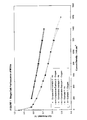
- Figure 1 shows the single cell performance of the MEAs manufactured from the membranes of Example 1, Comparative Example 1 and Comparative Example 2.
- the MEA performances are comparable and are typical of MEAs that are functioning satisfactorily under the selected single cell operating conditions. Particularly significant is the similar performances with pure O 2 as oxidant.
- the composite membrane of the invention (Example 1) performs comparably to un-reinforced Flemion SH-30 (Comparative Example 2) and to composite membranes prepared according to the prior art (Comparative Example 1), as disclosed in EP 875 524. That the membranes all exhibited a comparable resistance was confirmed by the similar MEA resistance of 0.06-0.07 ⁇ cm 2 recorded in-situ using the current-interrupt technique during the measurement of Figure 1.
- the composite membrane of the invention (Example 1) does not show an increase in resistance due to the reinforcement. This is an important feature of the composite membrane of the invention and is in keeping with the resistance of composite membranes prepared according to the prior art (Comparative Example 1).
- the cell potential with no current flowing through the MEA can be used as a guide to the H 2 gas cross-over from the anode to the cathode.
- OCV open circuit voltage
- the OCV of Example 1 at 0.955V is higher than the 0.933V for Comparative Example 1 and is comparable to the 0.961V for Comparative Example 2.
- the rate of H 2 cross-over more closely resembles the H 2 permeability through the un-reinforced Flemion SH-30 membrane (Comparative Example 2), which is a fundamental property of the membrane material.
- the rate of H 2 gas cross-over from the anode to the cathode of the MEA of Example 1, Comparative Example 1 and Comparative Example 2 was measured electrochemically. Maintaining the cell at 80°C and the reactant gas pressure at 200kPa absolute, H 2 (100% relative humidity) and N 2 (100 % relative humidity) were passed through the anode and cathode compartment respectively at a flow rate of 0.2slpm. A current density of 50mAcm -2 was sustained for 10 minutes to remove residual O 2 from the cathode compartment. The cell potential was varied from 200 to 800mV (in 100mV steps) and the current density measured after 30s. Extrapolating the linear region of the plot of cell potential vs.
- the H 2 gas cross-over rate is much lower through the composite membrane of Example 1 compared to the composite membrane of Comparative Example 1 and is close to the H 2 gas cross-over rate through the unreinforced Flemion SH-30 membrane, which is a fundamental property of the proton conducting membrane electrolyte.
- the N 2 gas leak-rate from anode to cathode was measured at 25°C using a pressure differential of 34 kPa abs from anode to cathode. N 2 at 134 kPa abs was admitted to the anode and the cathode outlet opened to ambient air conditions. The N 2 gas exiting the cathode outlet was collected in a graduated cylinder submerged in water to determine the volume of N 2 by H 2 O displacement.
- the N2 gas leak rate of Example 1 (2 cm 3 min -1 ) was significantly lower than Comparative Example 1 (43 cm 3 min -1 ) and much closer to Comparative Example 2 (0 cm 3 min -1 ).
- the composite membrane of Example 1 is significantly more leak tight than the composite membrane of Comparative Example 1, and is much closer to the un-reinforced Flemion SH-30 membrane of Comparative Example 2.
- Table 1 lists the OCVs, H 2 gas cross-over and N 2 gas leak-rate measurements for the MEAs of Example 1, Comparative Example 1, and Comparative Example 2. All measurements show the composite membrane of Example 1 is much more gas tight than the composite membrane of Comparative Example 1. The composite membrane of Example 1 has a comparable gas leak tightness to the un-reinforced Flemion SH-30 membrane of Comparative Example 2.
- Example 2 The dimensional stability of the composite membrane of the invention (Example 2) was measured and compared with both un-reinforced Flemion SH-30 membrane (Comparative Example 2) and an un-reinforced membrane prepared using the same Flemion FSS-1 ionomer material and the same production route (Comparative Example 3) used to prepare the composite membrane of the invention in Example 2.
- the membrane samples Prior to the dimensional stability measurements the membrane samples were pressed at 150°C and a pressure of 234 psi abs for 2 minutes so that the measurements more closely reflected the dimensional stability of the membrane in an MEA.
- 6cm x 6cm samples of the membranes were cut, placed between sheets of filter paper, and then placed between glass sheets. The membranes were dried for 2 to 2.5 hours at 60°C under vacuum. The dimensions of the dry membrane were measured. The membranes were subsequently boiled in water for one hour and then cooled to room temperature. The dimensions of the wet membrane were measured. The wet membranes were larger than the dry membranes, and the percentage expansion was calculated.
- Table 2 shows the percentage expansion of the membrane samples due to hydration in terms of both the x and y dimensions and the increase of membrane area.
- the composite membrane of the invention shows a 2% increase in the x dimension, a 16% increase in the y dimension and an 18% increase in area, compared with a 12% increase in the x dimension, a 38% increase in the y dimension and a 45% increase in the area for Flemion SH-30 (Comparative Example 2) and a 25% increase in both the x and y dimensions and a 44% increase in area for the membrane prepared from both the x and y dimensions and a 44% increase in area for the membrane prepared from the Flemion FSS-1 ionomer solution (Comparative Example 3).
- the composite membrane of the invention shows a significantly improved dimensional stability on hydration in terms of both the x and y dimensions and the increase of area compared with un-reinforced Flemion SH-30 (Comparative Example 2) and an un-reinforced membrane prepared from Flemion FSS-1 ionomer solution (Comparative Example 3). This is achieved even although the water take-up of the composite membrane of the invention (Example 2) is 50% higher than Flemion SH-30 (Comparative Example 2) and 15% higher than the un-reinforced membrane prepared from Flemion FSS-1 ionomer solution (Comparative Example 3). In un-reinforced membrane materials higher water-take-up leads to greater expansion of the membrane.
- This improved dimensional stability of the composite membranes of the invention will provide considerable benefit in terms of the ease of manufacture of MEAs incorporating the membranes.
- the improved dimensional stability is also likely to produce improved durability during prolonged MEA operation by minimising the mechanical stress in an MEA that can arise from the dimensional change of the membrane due to local changes in the level of membrane hydration.
Abstract
Description


Claims (31)
- A composite membrane comprising at least one ion-conducting polymer and fibres, characterised in that there is a continuous region of the membrane at one or both of the membrane faces wherein the density of fibres is lower than the density of fibres in the membrane as a whole.
- A composite membrane according to claim 1, wherein the fibres are a network of randomly orientated individual fibres.
- A composite membrane according to claim 1 or claim 2, wherein the continuous region of the membrane covers at least 25% of the surface area of the membrane.
- A composite membrane according to claim 3, wherein the continuous region of the membrane covers at least 50% of the surface area of the membrane.
- A composite membrane according to claim 4, wherein the continuous region of the membrane covers 100% of the surface area of the membrane.
- A composite membrane according to any preceding claim, wherein the thickness of the continuous region is at least 10% of the membrane thickness.
- A composite membrane according to claim 6, wherein the thickness of the continuous region is at least 20% of the membrane thickness.
- A composite membrane according to claim 6, wherein the thickness of the continuous region is at least 30% of the membrane thickness.
- A composite membrane according to any preceding claim, wherein the continuous region of the membrane contains less than 10% of the fibres in the membrane.
- A composite membrane according to claim 9, wherein the continuous region of the membrane contains less than 5% of the fibres in the membrane.
- A composite membrane according to any preceding claim, wherein the fibre density in the continuous region is zero.
- A composite membrane according to any preceding claim, wherein a continuous region with lower fibre density is present at only one membrane face.
- A composite membrane according to any one of claims 1 to 11, wherein a continuous region with low fibre density is present at each membrane face.
- A composite membrane according to any preceding claim, wherein the ion conducting polymers are proton conducting polymers.
- A composite membrane according to any preceding claim, wherein the total thickness of the membrane is less than 200µm.
- A composite membrane according to any preceding claim, wherein the fibres are amorphous silica fibres.
- A composite membrane according to any preceding claim, wherein the fibres are incorporated into the composite membrane at a fibre loading of 2 to 25wt%.
- A process for manufacturing a composite membrane according to any preceding claim, comprising steps whereina) a first coating composition comprising polymeric materials (either as a melt or a solution) and optionally comprising fibres is coated onto a backing layer to form a first polymer layer;b) a second coating composition comprising polymeric materials (either as a melt or a solution) and optionally comprising fibres is coated onto the layer produced from the first coating composition to form a second polymer layer on the first polymer layer; and wherein at least one of the two coating compositions comprises fibres.
- A process according to claim 18, wherein the first coating composition has a lower ratio of fibre: polymer than the second composition such that the first polymer layer has a lower fibre density than the second polymer layer.
- A process according to claim 19, wherein the first coating composition does not contain fibres, so that the first polymer layer does not contain fibres.
- A process according to any one of claims 18-20, wherein one or more additional coating compositions are coated onto the second polymer layer to form additional polymer layers.
- A process according to claim 21, wherein the first coating composition comprises polymeric material and no fibres, the second coating composition comprises polymeric material and fibres, and a third coating composition comprises polymeric material and no fibres, forming a membrane with fibre-free regions on both membrane faces.
- A process for manufacturing a composite membrane according to any one of claims 1 to 17, wherein a first membrane comprising a network of fibres is laminated to a second membrane that does not contain any fibres.
- A process for manufacturing a composite membrane according to any one of claims 1 to 17, wherein a region of ion-conducting polymer is applied to the surface of a membrane comprising a fibre network.
- A process for manufacturing a composite membrane according to any one of claims 1 to 17, wherein a region of ion-conducting polymer comprising a fibre network is applied to a membrane that does not comprise fibres.
- A process for manufacturing a composite membrane according to any one of claims 1 to 17, wherein the membrane is produced in a multi-layer extrusion process.
- A process for manufacturing a composite membrane according to any one of claims 1 to 17, wherein the membrane is co-moulded using an injection moulding process.
- A catalysed membrane comprising a composite membrane according to any one of claims 1 to 17.
- A membrane electrode assembly comprising a composite membrane according to any one of claims 1 to 17.
- A membrane electrode assembly comprising a composite membrane according to claim 12, wherein the continuous region with lower fibre density is adjacent to the cathode.
- A membrane electrode assembly comprising a composite membrane according to claim 12, wherein the continuous region with lower fibre density is adjacent to the anode.
Applications Claiming Priority (2)
| Application Number | Priority Date | Filing Date | Title |
|---|---|---|---|
| GBGB0210194.7A GB0210194D0 (en) | 2002-05-03 | 2002-05-03 | Composite membrane |
| GB0210194 | 2002-05-03 |
Publications (3)
| Publication Number | Publication Date |
|---|---|
| EP1359634A2 true EP1359634A2 (en) | 2003-11-05 |
| EP1359634A3 EP1359634A3 (en) | 2009-08-26 |
| EP1359634B1 EP1359634B1 (en) | 2020-03-18 |
Family
ID=9936040
Family Applications (1)
| Application Number | Title | Priority Date | Filing Date |
|---|---|---|---|
| EP03252423.3A Expired - Lifetime EP1359634B1 (en) | 2002-05-03 | 2003-04-16 | Composite membrane |
Country Status (5)
| Country | Link |
|---|---|
| US (1) | US7128993B2 (en) |
| EP (1) | EP1359634B1 (en) |
| JP (1) | JP5058429B2 (en) |
| CA (1) | CA2427264A1 (en) |
| GB (1) | GB0210194D0 (en) |
Cited By (1)
| Publication number | Priority date | Publication date | Assignee | Title |
|---|---|---|---|---|
| WO2013061054A1 (en) * | 2011-10-24 | 2013-05-02 | Johnson Matthey Fuel Cells Limited | Ion-conducting membrane |
Families Citing this family (9)
| Publication number | Priority date | Publication date | Assignee | Title |
|---|---|---|---|---|
| EP1518290A4 (en) * | 2002-05-13 | 2009-12-02 | Polyfuel Inc | Ion conductive block copolymers |
| KR20100022534A (en) * | 2002-06-28 | 2010-03-02 | 스미또모 가가꾸 가부시끼가이샤 | Polymeric laminates, processes for producing the same, and use thereof |
| TWI276654B (en) * | 2004-02-18 | 2007-03-21 | Ind Tech Res Inst | Proton exchange membrane (PEM) with different molecular permeation rates |
| KR100657918B1 (en) | 2004-12-11 | 2006-12-14 | 삼성에스디아이 주식회사 | Polymer electrolyte and fuel cell employing the same |
| JP4791822B2 (en) * | 2005-12-28 | 2011-10-12 | 株式会社東芝 | ELECTROLYTE MEMBRANE, METHOD FOR PRODUCING THE SAME, MEMBRANE ELECTRODE COMPLEX AND FUEL CELL USING THE SAME |
| KR20100125227A (en) * | 2007-12-17 | 2010-11-30 | 벤-구리온 유니버시티 오브 더 네게브 리서치 앤드 디벨럽먼트 어쏘러티 | Apparatus and system for deionization |
| US20130022895A1 (en) * | 2011-07-20 | 2013-01-24 | GM Global Technology Operations LLC | Membrane with Laminated Structure and Orientation Controlled Nanofiber Reinforcement Additives for Fuel Cells |
| US9123932B2 (en) * | 2011-11-17 | 2015-09-01 | GM Global Technology Operations LLC | Nanofiber supported catalysts as membrane additives for improved fuel cell durability |
| US9543607B2 (en) | 2013-02-22 | 2017-01-10 | National Research Council Of Canada | Process for producing ion exchange membranes by melt-processing of acidic PFSA ionomers |
Citations (5)
| Publication number | Priority date | Publication date | Assignee | Title |
|---|---|---|---|---|
| GB2302693A (en) * | 1995-06-26 | 1997-01-29 | Tokuyama Corp | Fluorine-containing resin moulded articles |
| EP0875524A2 (en) * | 1997-04-25 | 1998-11-04 | Johnson Matthey Public Limited Company | Composite membranes |
| WO2000023510A1 (en) * | 1998-10-16 | 2000-04-27 | Johnson Matthey Public Limited Company | Substrate |
| WO2001069705A1 (en) * | 2000-03-17 | 2001-09-20 | Johnson Matthey Public Limited Company | Proton conducting polymer membrane for electrochemical cell |
| EP1139472A1 (en) * | 2000-03-31 | 2001-10-04 | Asahi Glass Company Ltd. | Electrolyte membrane for solid polymer type fuel cell and producing method thereof |
Family Cites Families (30)
| Publication number | Priority date | Publication date | Assignee | Title |
|---|---|---|---|---|
| US3282875A (en) * | 1964-07-22 | 1966-11-01 | Du Pont | Fluorocarbon vinyl ether polymers |
| US4329435A (en) * | 1979-05-31 | 1982-05-11 | Asahi Kasei Kogyo Kabushiki Kaisha | Novel fluorinated copolymer with tridihydro fluorosulfonyl fluoride pendant groups and preparation thereof |
| US4330654A (en) * | 1980-06-11 | 1982-05-18 | The Dow Chemical Company | Novel polymers having acid functionality |
| US4358545A (en) * | 1980-06-11 | 1982-11-09 | The Dow Chemical Company | Sulfonic acid electrolytic cell having flourinated polymer membrane with hydration product less than 22,000 |
| US4417969A (en) * | 1980-06-11 | 1983-11-29 | The Dow Chemical Co. | Sulfonic acid electrolytic cell membranes |
| US4433082A (en) * | 1981-05-01 | 1984-02-21 | E. I. Du Pont De Nemours And Company | Process for making liquid composition of perfluorinated ion exchange polymer, and product thereof |
| US4610762A (en) * | 1985-05-31 | 1986-09-09 | The Dow Chemical Company | Method for forming polymer films having bubble release surfaces |
| US4940525A (en) * | 1987-05-08 | 1990-07-10 | The Dow Chemical Company | Low equivalent weight sulfonic fluoropolymers |
| GB8804858D0 (en) | 1988-03-01 | 1988-03-30 | Ici Plc | Organic polymeric material & ionexchange membrane produced therefrom |
| GB8813577D0 (en) | 1988-06-08 | 1988-07-13 | Ici Plc | Organic polymeric material & ion-exchange membrane produced therefrom |
| US5094995A (en) * | 1989-08-02 | 1992-03-10 | E. I. Du Pont De Nemours And Company | Supported perfluorinated ion-exchange polymers |
| US5068161A (en) | 1990-03-30 | 1991-11-26 | Johnson Matthey Public Limited Company | Catalyst material |
| SG73410A1 (en) * | 1992-06-13 | 2000-06-20 | Hoechst Ag | Polymer electrolyte membrane and process for the production thereof |
| WO1994003503A2 (en) * | 1992-07-30 | 1994-02-17 | Imperial Chemical Industries Plc | Fluorinated polymers |
| JP3385554B2 (en) * | 1992-09-25 | 2003-03-10 | 政廣 渡辺 | Polymer solid electrolyte composition and electrochemical cell using the composition |
| EP0679167A1 (en) | 1993-01-15 | 1995-11-02 | The Graver Company | Process for producing ion exchange membranes, and the ion exchange membranes produced thereby |
| US5422411A (en) | 1993-09-21 | 1995-06-06 | Ballard Power Systems Inc. | Trifluorostyrene and substituted trifluorostyrene copolymeric compositions and ion-exchange membranes formed therefrom |
| US5834523A (en) | 1993-09-21 | 1998-11-10 | Ballard Power Systems, Inc. | Substituted α,β,β-trifluorostyrene-based composite membranes |
| US5468574A (en) * | 1994-05-23 | 1995-11-21 | Dais Corporation | Fuel cell incorporating novel ion-conducting membrane |
| JP3541466B2 (en) * | 1994-12-19 | 2004-07-14 | 旭硝子株式会社 | Improved solid polymer electrolyte fuel cell |
| US5599639A (en) * | 1995-08-31 | 1997-02-04 | Hoechst Celanese Corporation | Acid-modified polybenzimidazole fuel cell elements |
| GB9622284D0 (en) | 1996-10-25 | 1996-12-18 | Johnson Matthey Plc | Improved catalyst |
| US20040208993A1 (en) * | 1998-10-16 | 2004-10-21 | Fongalland Dharshini Chryshantha | Substrate binder |
| GB9822571D0 (en) | 1998-10-16 | 1998-12-09 | Johnson Matthey Plc | Substrate binder |
| GB9826940D0 (en) | 1998-12-09 | 1999-02-03 | Johnson Matthey Plc | Electrode |
| JP2000234031A (en) * | 1999-02-16 | 2000-08-29 | Asahi Chem Ind Co Ltd | Production of ion-exchange membrane |
| JP2000260443A (en) * | 1999-03-04 | 2000-09-22 | Asahi Glass Co Ltd | Solid high polymer electrolyte fuel cell |
| JP3427003B2 (en) * | 1999-03-31 | 2003-07-14 | 株式会社東芝 | Fuel cell |
| US6689501B2 (en) * | 2001-05-25 | 2004-02-10 | Ballard Power Systems Inc. | Composite ion exchange membrane for use in a fuel cell |
| JP2003317748A (en) * | 2002-04-23 | 2003-11-07 | Araco Corp | Solid polyelectrolyte film |
-
2002
- 2002-05-03 GB GBGB0210194.7A patent/GB0210194D0/en not_active Ceased
-
2003
- 2003-04-16 EP EP03252423.3A patent/EP1359634B1/en not_active Expired - Lifetime
- 2003-04-30 CA CA002427264A patent/CA2427264A1/en not_active Abandoned
- 2003-05-02 US US10/429,142 patent/US7128993B2/en active Active
- 2003-05-06 JP JP2003127827A patent/JP5058429B2/en not_active Expired - Lifetime
Patent Citations (5)
| Publication number | Priority date | Publication date | Assignee | Title |
|---|---|---|---|---|
| GB2302693A (en) * | 1995-06-26 | 1997-01-29 | Tokuyama Corp | Fluorine-containing resin moulded articles |
| EP0875524A2 (en) * | 1997-04-25 | 1998-11-04 | Johnson Matthey Public Limited Company | Composite membranes |
| WO2000023510A1 (en) * | 1998-10-16 | 2000-04-27 | Johnson Matthey Public Limited Company | Substrate |
| WO2001069705A1 (en) * | 2000-03-17 | 2001-09-20 | Johnson Matthey Public Limited Company | Proton conducting polymer membrane for electrochemical cell |
| EP1139472A1 (en) * | 2000-03-31 | 2001-10-04 | Asahi Glass Company Ltd. | Electrolyte membrane for solid polymer type fuel cell and producing method thereof |
Cited By (2)
| Publication number | Priority date | Publication date | Assignee | Title |
|---|---|---|---|---|
| WO2013061054A1 (en) * | 2011-10-24 | 2013-05-02 | Johnson Matthey Fuel Cells Limited | Ion-conducting membrane |
| US10530002B2 (en) | 2011-10-24 | 2020-01-07 | Johnson Matthey Fuel Cells Limited | Ion-conducting membrane |
Also Published As
| Publication number | Publication date |
|---|---|
| JP2003346839A (en) | 2003-12-05 |
| GB0210194D0 (en) | 2002-06-12 |
| US20040009385A1 (en) | 2004-01-15 |
| JP5058429B2 (en) | 2012-10-24 |
| US7128993B2 (en) | 2006-10-31 |
| EP1359634B1 (en) | 2020-03-18 |
| CA2427264A1 (en) | 2003-11-03 |
| EP1359634A3 (en) | 2009-08-26 |
Similar Documents
| Publication | Publication Date | Title |
|---|---|---|
| US6602630B1 (en) | Membrane electrode assemblies for electrochemical cells | |
| JP3827018B2 (en) | Membrane containing inorganic filler and membrane-electrode assembly and electrochemical cell using the same | |
| US6042958A (en) | Composite membranes | |
| US7803495B2 (en) | Polymer electrolyte membrane for fuel cell, method for preparing the same, and fuel cell system comprising the same | |
| EP1133806B1 (en) | Process for preparing a solid polymer electrolyte membrane | |
| US20140315121A1 (en) | Method for the preparation of catalyst-coated membranes method for the preparation of catalyst-coated membranes | |
| CA2275755A1 (en) | Multiple layer membranes for fuel cells employing direct feed fuels | |
| JP2011508952A (en) | Production of catalyst coated membrane | |
| US20080118808A1 (en) | Electrolyte membrane for polymer electrolyte fuel cell, process for its production and membrane-electrode assembly for polymer electrolyte fuel cell | |
| KR20220057565A (en) | membrane electrode assembly | |
| CA2664373A1 (en) | Structures for gas diffusion electrodes | |
| EP1359634B1 (en) | Composite membrane | |
| KR101228648B1 (en) | Gas deffusion electrode, membrane-electrode assemblies and method for the production thereof | |
| JPH10334923A (en) | Solid high polymer fuel cell film/electrode connecting body | |
| KR101064225B1 (en) | Membrane-Electrode Assembly including guarding gasket | |
| Scott | Membrane electrode assemblies for polymer electrolyte membrane fuel cells | |
| US20040209965A1 (en) | Process for preparing a solid polymer electrolyte membrane | |
| US20230352713A1 (en) | Membrane and process | |
| WO2023148498A2 (en) | Catalyst coated membranes for water electrolysers | |
| JP2021190176A (en) | Membrane electrode gas diffusion layer assembly for fuel battery cell | |
| WO2003069713A1 (en) | Membrane electrode assemblies for electrochemical cells | |
| Du et al. | 12 materials for Proton exchange membrane fuel Cells | |
| EP2219257A1 (en) | Fuel cell comprising an ion-conductive membrane | |
| JP2007157429A (en) | Manufacturing method of fuel cell |
Legal Events
| Date | Code | Title | Description |
|---|---|---|---|
| PUAI | Public reference made under article 153(3) epc to a published international application that has entered the european phase |
Free format text: ORIGINAL CODE: 0009012 |
|
| AK | Designated contracting states |
Kind code of ref document: A2 Designated state(s): AT BE BG CH CY CZ DE DK EE ES FI FR GB GR HU IE IT LI LU MC NL PT RO SE SI SK TR |
|
| AX | Request for extension of the european patent |
Extension state: AL LT LV MK |
|
| PUAL | Search report despatched |
Free format text: ORIGINAL CODE: 0009013 |
|
| AK | Designated contracting states |
Kind code of ref document: A3 Designated state(s): AT BE BG CH CY CZ DE DK EE ES FI FR GB GR HU IE IT LI LU MC NL PT RO SE SI SK TR |
|
| AX | Request for extension of the european patent |
Extension state: AL LT LV MK |
|
| RIC1 | Information provided on ipc code assigned before grant |
Ipc: H01M 8/10 20060101AFI20030905BHEP Ipc: C08J 5/22 20060101ALI20090720BHEP Ipc: D04H 5/02 20060101ALI20090720BHEP Ipc: B01D 69/12 20060101ALI20090720BHEP |
|
| 17P | Request for examination filed |
Effective date: 20100211 |
|
| 17Q | First examination report despatched |
Effective date: 20100318 |
|
| AKX | Designation fees paid |
Designated state(s): AT BE BG CH CY CZ DE DK EE ES FI FR GB GR HU IE IT LI LU MC NL PT RO SE SI SK TR |
|
| RAP1 | Party data changed (applicant data changed or rights of an application transferred) |
Owner name: JOHNSON MATTHEY FUEL CELLS LIMITED |
|
| REG | Reference to a national code |
Ref country code: DE Ref legal event code: R079 Ref document number: 60352412 Country of ref document: DE Free format text: PREVIOUS MAIN CLASS: H01M0008100000 Ipc: H01M0008102300 |
|
| GRAP | Despatch of communication of intention to grant a patent |
Free format text: ORIGINAL CODE: EPIDOSNIGR1 |
|
| STAA | Information on the status of an ep patent application or granted ep patent |
Free format text: STATUS: GRANT OF PATENT IS INTENDED |
|
| RIC1 | Information provided on ipc code assigned before grant |
Ipc: B01D 69/12 20060101ALI20190110BHEP Ipc: H01M 8/1053 20160101ALI20190110BHEP Ipc: H01B 1/12 20060101ALI20190110BHEP Ipc: H01M 8/1007 20160101ALI20190110BHEP Ipc: H01M 8/1051 20160101ALI20190110BHEP Ipc: C08J 5/22 20060101ALI20190110BHEP Ipc: B01D 69/14 20060101ALI20190110BHEP Ipc: B01J 35/06 20060101ALI20190110BHEP Ipc: H01M 8/1039 20160101ALI20190110BHEP Ipc: H01M 8/1023 20160101AFI20190110BHEP Ipc: H01M 8/1069 20160101ALI20190110BHEP Ipc: H01M 8/1081 20160101ALI20190110BHEP |
|
| INTG | Intention to grant announced |
Effective date: 20190208 |
|
| GRAJ | Information related to disapproval of communication of intention to grant by the applicant or resumption of examination proceedings by the epo deleted |
Free format text: ORIGINAL CODE: EPIDOSDIGR1 |
|
| STAA | Information on the status of an ep patent application or granted ep patent |
Free format text: STATUS: EXAMINATION IS IN PROGRESS |
|
| INTC | Intention to grant announced (deleted) | ||
| GRAP | Despatch of communication of intention to grant a patent |
Free format text: ORIGINAL CODE: EPIDOSNIGR1 |
|
| STAA | Information on the status of an ep patent application or granted ep patent |
Free format text: STATUS: GRANT OF PATENT IS INTENDED |
|
| INTG | Intention to grant announced |
Effective date: 20190712 |
|
| GRAJ | Information related to disapproval of communication of intention to grant by the applicant or resumption of examination proceedings by the epo deleted |
Free format text: ORIGINAL CODE: EPIDOSDIGR1 |
|
| STAA | Information on the status of an ep patent application or granted ep patent |
Free format text: STATUS: EXAMINATION IS IN PROGRESS |
|
| GRAP | Despatch of communication of intention to grant a patent |
Free format text: ORIGINAL CODE: EPIDOSNIGR1 |
|
| STAA | Information on the status of an ep patent application or granted ep patent |
Free format text: STATUS: GRANT OF PATENT IS INTENDED |
|
| INTC | Intention to grant announced (deleted) | ||
| INTG | Intention to grant announced |
Effective date: 20191213 |
|
| GRAS | Grant fee paid |
Free format text: ORIGINAL CODE: EPIDOSNIGR3 |
|
| GRAA | (expected) grant |
Free format text: ORIGINAL CODE: 0009210 |
|
| STAA | Information on the status of an ep patent application or granted ep patent |
Free format text: STATUS: THE PATENT HAS BEEN GRANTED |
|
| REG | Reference to a national code |
Ref country code: DE Ref legal event code: R081 Ref document number: 60352412 Country of ref document: DE Owner name: JOHNSON MATTHEY HYDROGEN TECHNOLOGIES LIMITED, GB Free format text: FORMER OWNER: JOHNSON MATTHEY PLC, LONDON, GB |
|
| AK | Designated contracting states |
Kind code of ref document: B1 Designated state(s): AT BE BG CH CY CZ DE DK EE ES FI FR GB GR HU IE IT LI LU MC NL PT RO SE SI SK TR |
|
| REG | Reference to a national code |
Ref country code: GB Ref legal event code: FG4D |
|
| REG | Reference to a national code |
Ref country code: DE Ref legal event code: R096 Ref document number: 60352412 Country of ref document: DE |
|
| REG | Reference to a national code |
Ref country code: AT Ref legal event code: REF Ref document number: 1246980 Country of ref document: AT Kind code of ref document: T Effective date: 20200415 Ref country code: IE Ref legal event code: FG4D |
|
| PG25 | Lapsed in a contracting state [announced via postgrant information from national office to epo] |
Ref country code: FI Free format text: LAPSE BECAUSE OF FAILURE TO SUBMIT A TRANSLATION OF THE DESCRIPTION OR TO PAY THE FEE WITHIN THE PRESCRIBED TIME-LIMIT Effective date: 20200318 |
|
| REG | Reference to a national code |
Ref country code: NL Ref legal event code: MP Effective date: 20200318 |
|
| PG25 | Lapsed in a contracting state [announced via postgrant information from national office to epo] |
Ref country code: SE Free format text: LAPSE BECAUSE OF FAILURE TO SUBMIT A TRANSLATION OF THE DESCRIPTION OR TO PAY THE FEE WITHIN THE PRESCRIBED TIME-LIMIT Effective date: 20200318 Ref country code: GR Free format text: LAPSE BECAUSE OF FAILURE TO SUBMIT A TRANSLATION OF THE DESCRIPTION OR TO PAY THE FEE WITHIN THE PRESCRIBED TIME-LIMIT Effective date: 20200619 Ref country code: BG Free format text: LAPSE BECAUSE OF FAILURE TO SUBMIT A TRANSLATION OF THE DESCRIPTION OR TO PAY THE FEE WITHIN THE PRESCRIBED TIME-LIMIT Effective date: 20200618 |
|
| PG25 | Lapsed in a contracting state [announced via postgrant information from national office to epo] |
Ref country code: NL Free format text: LAPSE BECAUSE OF FAILURE TO SUBMIT A TRANSLATION OF THE DESCRIPTION OR TO PAY THE FEE WITHIN THE PRESCRIBED TIME-LIMIT Effective date: 20200318 |
|
| PG25 | Lapsed in a contracting state [announced via postgrant information from national office to epo] |
Ref country code: RO Free format text: LAPSE BECAUSE OF FAILURE TO SUBMIT A TRANSLATION OF THE DESCRIPTION OR TO PAY THE FEE WITHIN THE PRESCRIBED TIME-LIMIT Effective date: 20200318 Ref country code: CZ Free format text: LAPSE BECAUSE OF FAILURE TO SUBMIT A TRANSLATION OF THE DESCRIPTION OR TO PAY THE FEE WITHIN THE PRESCRIBED TIME-LIMIT Effective date: 20200318 Ref country code: EE Free format text: LAPSE BECAUSE OF FAILURE TO SUBMIT A TRANSLATION OF THE DESCRIPTION OR TO PAY THE FEE WITHIN THE PRESCRIBED TIME-LIMIT Effective date: 20200318 Ref country code: PT Free format text: LAPSE BECAUSE OF FAILURE TO SUBMIT A TRANSLATION OF THE DESCRIPTION OR TO PAY THE FEE WITHIN THE PRESCRIBED TIME-LIMIT Effective date: 20200812 Ref country code: SK Free format text: LAPSE BECAUSE OF FAILURE TO SUBMIT A TRANSLATION OF THE DESCRIPTION OR TO PAY THE FEE WITHIN THE PRESCRIBED TIME-LIMIT Effective date: 20200318 |
|
| REG | Reference to a national code |
Ref country code: AT Ref legal event code: MK05 Ref document number: 1246980 Country of ref document: AT Kind code of ref document: T Effective date: 20200318 |
|
| REG | Reference to a national code |
Ref country code: CH Ref legal event code: PL |
|
| REG | Reference to a national code |
Ref country code: DE Ref legal event code: R097 Ref document number: 60352412 Country of ref document: DE |
|
| PG25 | Lapsed in a contracting state [announced via postgrant information from national office to epo] |
Ref country code: MC Free format text: LAPSE BECAUSE OF FAILURE TO SUBMIT A TRANSLATION OF THE DESCRIPTION OR TO PAY THE FEE WITHIN THE PRESCRIBED TIME-LIMIT Effective date: 20200318 |
|
| PLBE | No opposition filed within time limit |
Free format text: ORIGINAL CODE: 0009261 |
|
| STAA | Information on the status of an ep patent application or granted ep patent |
Free format text: STATUS: NO OPPOSITION FILED WITHIN TIME LIMIT |
|
| PG25 | Lapsed in a contracting state [announced via postgrant information from national office to epo] |
Ref country code: LI Free format text: LAPSE BECAUSE OF NON-PAYMENT OF DUE FEES Effective date: 20200430 Ref country code: ES Free format text: LAPSE BECAUSE OF FAILURE TO SUBMIT A TRANSLATION OF THE DESCRIPTION OR TO PAY THE FEE WITHIN THE PRESCRIBED TIME-LIMIT Effective date: 20200318 Ref country code: CH Free format text: LAPSE BECAUSE OF NON-PAYMENT OF DUE FEES Effective date: 20200430 Ref country code: IT Free format text: LAPSE BECAUSE OF FAILURE TO SUBMIT A TRANSLATION OF THE DESCRIPTION OR TO PAY THE FEE WITHIN THE PRESCRIBED TIME-LIMIT Effective date: 20200318 Ref country code: AT Free format text: LAPSE BECAUSE OF FAILURE TO SUBMIT A TRANSLATION OF THE DESCRIPTION OR TO PAY THE FEE WITHIN THE PRESCRIBED TIME-LIMIT Effective date: 20200318 Ref country code: LU Free format text: LAPSE BECAUSE OF NON-PAYMENT OF DUE FEES Effective date: 20200416 Ref country code: DK Free format text: LAPSE BECAUSE OF FAILURE TO SUBMIT A TRANSLATION OF THE DESCRIPTION OR TO PAY THE FEE WITHIN THE PRESCRIBED TIME-LIMIT Effective date: 20200318 |
|
| REG | Reference to a national code |
Ref country code: BE Ref legal event code: MM Effective date: 20200430 |
|
| 26N | No opposition filed |
Effective date: 20201221 |
|
| PG25 | Lapsed in a contracting state [announced via postgrant information from national office to epo] |
Ref country code: BE Free format text: LAPSE BECAUSE OF NON-PAYMENT OF DUE FEES Effective date: 20200430 |
|
| PG25 | Lapsed in a contracting state [announced via postgrant information from national office to epo] |
Ref country code: IE Free format text: LAPSE BECAUSE OF NON-PAYMENT OF DUE FEES Effective date: 20200416 Ref country code: FR Free format text: LAPSE BECAUSE OF NON-PAYMENT OF DUE FEES Effective date: 20200518 |
|
| PG25 | Lapsed in a contracting state [announced via postgrant information from national office to epo] |
Ref country code: SI Free format text: LAPSE BECAUSE OF FAILURE TO SUBMIT A TRANSLATION OF THE DESCRIPTION OR TO PAY THE FEE WITHIN THE PRESCRIBED TIME-LIMIT Effective date: 20200318 |
|
| PGFP | Annual fee paid to national office [announced via postgrant information from national office to epo] |
Ref country code: GB Payment date: 20220323 Year of fee payment: 20 |
|
| PG25 | Lapsed in a contracting state [announced via postgrant information from national office to epo] |
Ref country code: TR Free format text: LAPSE BECAUSE OF FAILURE TO SUBMIT A TRANSLATION OF THE DESCRIPTION OR TO PAY THE FEE WITHIN THE PRESCRIBED TIME-LIMIT Effective date: 20200318 Ref country code: CY Free format text: LAPSE BECAUSE OF FAILURE TO SUBMIT A TRANSLATION OF THE DESCRIPTION OR TO PAY THE FEE WITHIN THE PRESCRIBED TIME-LIMIT Effective date: 20200318 |
|
| REG | Reference to a national code |
Ref country code: DE Ref legal event code: R081 Ref document number: 60352412 Country of ref document: DE Owner name: JOHNSON MATTHEY HYDROGEN TECHNOLOGIES LIMITED, GB Free format text: FORMER OWNER: JOHNSON MATTHEY FUEL CELLS LIMITED, LONDON, GB |
|
| PGFP | Annual fee paid to national office [announced via postgrant information from national office to epo] |
Ref country code: DE Payment date: 20220322 Year of fee payment: 20 |
|
| REG | Reference to a national code |
Ref country code: DE Ref legal event code: R071 Ref document number: 60352412 Country of ref document: DE |
|
| REG | Reference to a national code |
Ref country code: GB Ref legal event code: PE20 Expiry date: 20230415 |
|
| P01 | Opt-out of the competence of the unified patent court (upc) registered |
Effective date: 20230526 |
|
| PG25 | Lapsed in a contracting state [announced via postgrant information from national office to epo] |
Ref country code: GB Free format text: LAPSE BECAUSE OF EXPIRATION OF PROTECTION Effective date: 20230415 |