BACKGROUND OF THE INVENTION
Field of the Invention:
The present invention relates to a droplet-jetting
device such as an ink-jet head of an ink-jet printer.
Description of the Related Art:
An apparatus has been hitherto suggested, in which
a piezoelectric droplet-jetting device is utilized for a
print head. This device is constructed such that the volume
of a liquid chamber is changed by the dimensional
displacement of a piezoelectric actuator, and thus the liquid
(ink) contained in the liquid chamber is jetted from a nozzle
during the decrease of the volume, while the ink is
introduced into the liquid chamber during the increase of the
volume. A large number of the droplet-jetting devices as
described above are arranged closely to one another, and the
ink is jetted from the droplet-jetting device disposed at a
predetermined position. Accordingly, a desired letter or an
image is formed.
For example, Fig. 28 shows an ink-jet print head
which utilizes the conventional piezoelectric droplet-jetting
device. Fig. 28 shows a magnified sectional view
illustrating the conventional piezoelectric ink-jet head.
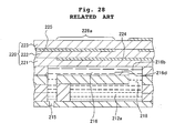
The piezoelectric ink-jet head comprises nozzles 215 which
are open to the outside, pressure chambers 216 which supply
the ink to the nozzles 215, a common ink chamber 212a which
distributes the ink from an unillustrated ink supply source
to the plurality of pressure chambers 216 via ink supply
holes 218, 216b and throttle sections 216d, and a
piezoelectric actuator 220 provided with pressure-generating
sections 228 which apply the pressure to jet the ink to the
pressure chambers 216.
The pressure-generating section 228 is a portion of
the piezoelectric actuator 220 at which a piezoelectric sheet
222 of the piezoelectric actuator 220 is interposed between a
driving electrode 224 and a common electrode 225. The
pressure-generating section 228 is subjected to the
polarization treatment in a direction directed from the
driving electrode 224 to the common electrode 225. When an
electric field, which matches the direction in which the
polarization treatment is applied, is applied between the
driving electrode 224 and the common electrode 225, the
pressure-generating section 228 causes the elongation
displacement in the thickness direction of the piezoelectric
actuator 220. As a result of the displacement, the volume of
the pressure chamber 216 is decreased, and the ink contained
in the pressure chamber 216 is extruded. Accordingly, ink
droplets are jetted from the nozzle 215 which is communicated
with the pressure chamber 216.
In order to jet the ink droplets having necessary
jetting velocities and volumes more efficiently, i.e., at a
lower voltage, the pressure-generating section 228 has been
arranged in a region approximately ranging over the entire
pressure chamber 216.
However, the conventional piezoelectric ink-jet
print head as described above has involved the following
problems, because the pressure-generating section has been
arranged in the region approximately ranging over the entire
pressure chamber. That is, the electrostatic capacity, which
is proportional to the area of the pressure-generating
section, is increased. The energy efficiency is
unsatisfactory. The power source system, which is used to
drive the ink-jet print head, suffers from the increase in
cost.
The piezoelectric ink-jet print head as described
above is suitable for the so-called "push-eject" in which the
ink droplets are jetted by decreasing the volume of the
pressure chamber when the driving voltage is applied.
However, when such a method is used, a problem arises such
that the supply of the ink is not performed in time, and it
is impossible to increase the driving frequency so much.
Further, when such a method is used, a problem arises such
that the volume of the ink droplet cannot be increased so
much as well.
Therefore, it is intended to perform the so-called
"pull-eject" as a method for increasing the driving frequency
and increasing the volume of the droplet, in which the volume
of the pressure chamber is firstly increased, and then the
volume of the pressure chamber is restored to the original
volume at the timing at which the pressure in the pressure
chamber is changed from the negative to the positive. In
this case, it is necessary to use such a method that the
volume of the pressure chamber is always decreased by always
applying a voltage, and the voltage application is shut off
only when the printing operation is performed. Therefore,
the energy efficiency has been extremely unsatisfactory.
In such a method, it is also conceived that a
reverse electric field is applied in order to increase the
volume of the ink chamber. However, if such a procedure is
adopted, only a low electric field, which causes no
polarization reversal, can be applied. It is impossible to
jet any sufficient amount of ink droplets.
SUMMARY OF THE INVENTION
The present invention has been made in order to
solve the problems as described above, a first object of
which is to provide a droplet-jetting device in which the
electrostatic capacity is suppressed to improve the energy
efficiency and the voltage is applied only when the device is
driven so that the pull-eject is successfully performed, and
an ink-jet recording apparatus provided with the same. A
second object of the present invention is to provide a
droplet-jetting device which makes it possible to increase
the driving frequency and which makes it possible to increase
the volume of the liquid droplet, and an ink-jet recording
apparatus provided with the same.
According to the present invention there is
provided a droplet-jetting device comprising a nozzle which
jets a liquid, a pressure chamber which supplies the liquid
to the nozzle, and a pressure-generating section which
applies a pressure to the pressure chamber in order to jet
the liquid from the nozzle; wherein a wall surface, which
defines the pressure chamber, is displaceable to vary a
volume of the pressure chamber; and the droplet-jetting
device further comprises a connecting section which connects
the pressure-generating section to the wall surface to
transmit displacement of the pressure-generating section to
the wall surface.
In the droplet-jetting device of the present
invention, the displacement of the pressure-generating
section is transmitted via the connecting section to the wall
surface of the pressure chamber disposed opposingly thereto.
Accordingly, even when the amount of displacement volume of
the pressure-generating section is small, it is possible to
obtain a large volume change of the pressure chamber.
Therefore, even when the pressure-generating section is moved
such that a part of the volume of the pressure chamber is
replaced therewith during the driving, it is possible to
expand the volume of the entire pressure chamber. The
pressure-generating section is thereafter restored, and thus
the volume is restored to the original volume. Accordingly,
it is possible to perform the pull-eject. When the
connecting section is provided, it is possible to expand the
pressure chamber when the pressure-generating section is
elongated toward the pressure chamber. Accordingly, it is
possible to realize the pull-eject in which the volume change
is large.
In the droplet-ejection device of the present
invention, when the pressure-generating section is displaced,
while the displacement of the connecting section does not
directly change the volume of the pressure chamber, the wall
surface may increase the volume of the pressure chamber.
The droplet-jetting device of the present invention
may further comprise an actuator unit which covers a surface
opposed to the wall surface of the pressure chamber and which
includes the pressure-generating section, wherein the
pressure-generating section may effect the displacement in an
area which is smaller than the surface of the pressure
chamber opposed to the wall surface. In the droplet-jetting
device of this arrangement, the displacement of the pressure-generating
section, which is caused in the small area, is
transmitted to the wall surface of the pressure chamber which
is wider than the above. Therefore, it is possible to obtain
the desired change of the volume of the pressure chamber by
using the energy smaller than that used in the conventional
technique.
The droplet-jetting device of the present invention
may be structured such that the wall surface of the pressure
chamber has one end which is disposed in a longitudinal
direction of the pressure chamber and which serves as a
support point, and the other end which is displaceable about
the support point in the direction to vary the volume of the
pressure chamber. In this structure, the other end of the
pressure chamber is depressed downwardly by using the support
point of one end of the pressure chamber in the longitudinal
direction. Therefore, it is possible to increase the
volumetric displacement of the pressure chamber. In this
arrangement, an area of the actuator unit to be displaced by
the pressure-generating section may be about 5 % to 40 % with
respect to an area of the surface of the pressure chamber.
When this areal ratio is adopted, it is possible to more
greatly expand the volume of the pressure chamber more easily
by means of the areal displacement of the pressure-generating
section.
In the droplet-jetting device of the present
invention, the pressure chamber may have one end which is
disposed in a longitudinal direction and which is
communicated with the nozzle, and the other end which is
communicated with an ink supply source via a throttle section
having a cross section smaller than that of the pressure
chamber, and the connecting section may be composed of a wall
portion which comparts the throttle section. In this
arrangement, the connecting section is constructed by the
wall portion for forming the throttle section which is
necessary to increase the flow passage resistance.
Therefore, the droplet-jetting device can be produced without
increasing the number of parts and without complicating the
production steps.
In the droplet-jetting device of the present
invention, the pressure chamber may be composed of a
plurality of chambers which are arranged in array, a common
liquid chamber may be provided to distribute the liquid to
the respective chambers, the common liquid chamber may extend
in a direction of the array of the respective chambers on a
side opposite to the respective chambers with wall sections
for constituting the wall surfaces of the respective chambers
intervening therebetween, and each of the wall sections for
constituting the wall surfaces may be displaced toward the
common liquid chamber by the displacement of the pressure-generating
section. In this arrangement, the common liquid
chamber is adjacent to the respective chambers. Accordingly,
each of the chambers is expanded toward the common liquid
chamber in accordance with the displacement of the wall
surface. Therefore, it is possible to realize the
displacement of the wall surface of each of the chambers
without preparing any special space.
The droplet-jetting device of the present invention
may further comprise a first plate which has a first opening
corresponding to the pressure chamber formed penetratingly in
a plate thickness direction, a second plate which has a
second opening corresponding to the common liquid chamber
formed penetratingly in the plate thickness direction, and a
third plate which has the wall section disposed between the
pressure chamber and the common liquid chamber, wherein the
third plate may be positioned between the first and second
plates. When the common liquid chamber and the pressure
chamber have the stacked structure as described above, it is
possible to easily realize the droplet-jetting device of the
present invention.
In the droplet-jetting device of the present
invention, the pressure-generating section may include a
piezoelectric material and electrodes which are positioned
opposingly in a direction of polarization thereof, and the
piezoelectric material may be elongated by application of a
voltage to the electrodes. In this arrangement, the
piezoelectric material is elongated by the application of the
voltage so that piezoelectric material enters the pressure
chamber. However, it is possible to obtain the desired
change of the volume of the pressure chamber by using the
pressure-generating section having the area smaller than that
used in the conventional technique as described above. It is
possible to suppress the applied voltage as compared with the
conventional technique, and it is possible to decrease the
electrostatic capacity.
In the droplet-jetting device of the present
invention, when the pressure-generating section is displaced,
a volumetric change of the pressure chamber by displacement
of the wall surface is greater than a volumetric change of
the pressure chamber by displacement of the connecting
section.
The droplet-jetting device of the present invention
may further comprise a vibration plate which is disposed
between the pressure chamber and the pressure-generating
section, the vibration plate including a first portion which
serves as the connecting section and a second portion which
serves as the wall surface, the first portion and the second
portion being displaceable in cooperation with each other
with a support point section intervening therebetween, the
pressure-generating section being arranged opposingly to the
first portion, and the second portion being arranged
opposingly to the pressure chamber; wherein the first portion
may be displaced by the pressure applied by the pressure-generating
section, and thus the second portion, which is
disposed on a side opposite to the first portion with the
support point section intervening therebetween, may be
displaced to cause a large volumetric change to the pressure
chamber than caused by the first portion. In this droplet-jetting
device, when the pressure is applied to the first
portion from the pressure-generating section to displace the
first portion, the second portion is displaced toward the
side opposite to the first portion more greatly than the
first portion. Accordingly, even when the pressure-generating
section for applying the pressure to the first
portion has a small area, i.e., even when the energy is
small, it is possible to cause the large volumetric change to
the pressure chamber by displacement of the second portion.
In the droplet-jetting device of the present
invention, the first portion and the second portion may be
aligned and positioned in a longitudinal direction of the
pressure chamber, and the second portion may be longer than
the first portion in the longitudinal direction. In this
arrangement, when the first portion is displaced by applying
the pressure to the first portion, the second portion is
displaced toward the side opposite to the first portion more
greatly than the first portion in accordance with the lever
principle, because the second portion is longer than the
first portion in the longitudinal direction. Accordingly, it
is possible to cause the large volumetric change to the
pressure chamber by displacement of the second portion even
when the pressure-generating section for applying the
pressure to the first portion has the small area.
In the droplet-jetting device of the present
invention, the pressure-generating section may include a
piezoelectric material and electrodes which are positioned
opposingly in a direction of polarization thereof, and the
piezoelectric material may be elongated by application of a
voltage to the electrodes. The second portion may be
displaced to expand the pressure chamber in a direction
opposite to the displacement of the first portion brought
about by the elongation of the piezoelectric material. In
this arrangement, when the voltage is applied to the
electrodes of the pressure-generating section, then the
piezoelectric material is elongated to displace the first
portion, and the support point section serves as a lever so
that the second portion is displaced toward the side opposite
to the first portion to expand the pressure chamber.
Therefore, the pressure chamber is greatly expanded in
accordance with the lever principle even when the area of the
pressure-generating section is small. Accordingly, it is
possible to decrease the electrostatic capacity of the
pressure-generating section, and it is possible to suppress
the voltage to be low. Further, when the voltage is applied,
the second portion is displaced to expand the pressure
chamber. Therefore, it is possible to perform the pull-eject
by applying the voltage during the jetting. It is possible
to reduce the cost of the power source system as compared
with a method in which the voltage is always applied while
the voltage is shut off during the jetting.
The droplet-jetting device of the present invention
may further comprise an actuator unit which covers the entire
pressure chamber and which includes the pressure-generating
section, wherein the pressure-generating section may be
positioned opposingly to the first portion of the vibration
plate, the vibration plate may abut against the pressure-generating
section at the first portion, and a space may be
formed between the second portion and the actuator unit. In
this arrangement, when the voltage is applied to the
electrodes of the pressure-generating section, then the first
portion of the vibration plate opposed to the pressure-generating
section is displaced, and the second portion is
displaced about the support point section toward the space
provided between the second portion and the actuator unit.
Thus, it is possible to expand the volume of the pressure
chamber.
In the droplet-jetting device of the present
invention, the pressure chamber may include a plurality of
chambers, the actuator unit and the vibration plate may
extend to span the plurality of chambers, and the pressure-generating
section may include a plurality of generating
sections which are provided for the actuator unit
corresponding to the plurality of chambers. In this
arrangement, one actuator unit and one vibration plate are
used to span the plurality of nozzles and the plurality of
chambers. Therefore, a large number of jetting mechanisms
can be accumulated to enhance the resolution.
In the droplet-jetting device of the present
invention, the vibration plate may have a projection which
abuts against the actuator unit between the first portion and
the second portion, and the vibration plate may be displaced
by using those disposed in the vicinity of the projection as
the support point section. In this arrangement, the
projection is formed on the vibration plate. Accordingly,
the support point, about which the vibration plate makes the
motion like a lever, can be formed with ease without
requiring any special member.
In the droplet-jetting device of the present
invention, the first portion of the vibration plate may be
positioned outside the pressure chamber, and the vibration
plate may be displaced by using, as the support point, those
disposed in the vicinity of a portion of the vibration plate
to make abutment against an outer wall of the pressure
chamber between the first portion and the second portion. In
this arrangement, the first portion is not displaced into the
pressure chamber, but the entire pressure chamber is deformed
in an identical direction by means of the second portion.
Therefore, the volume of the pressure chamber is not
decreased, and it is possible to efficiently expand the
volume of the pressure chamber.
In the droplet-jetting device of the present
invention, owing to the provision of the connecting section,
an area of the pressure-generating section can be made
smaller than about 60 % of an area of the wall surface of the
pressure chamber. Accordingly, it is possible to suppress
the electrostatic capacity, and it is possible to improve the
energy efficiency.
According to another aspect of the present
invention, there is provided an ink-jet recording apparatus
comprising the droplet-jetting device of the present
invention. The ink-jet recording apparatus makes it possible
to perform the recording at a high speed and a high
resolution, because the ink-jet recording apparatus is
provided with the droplet-jetting device of the present
invention.
BRIEF DESCRIPTION OF THE DRAWINGS
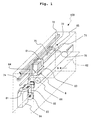
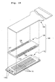
Fig. 1 shows a perspective view illustrating a schematic
structure of an ink-jet printer 100 which carries a
piezoelectric ink-jet head 6 according to an embodiment of
the present invention.
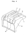
Fig. 2 shows a perspective view illustrating a state in
which a head unit 63 is inverted upside down.
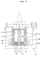
Fig. 3 shows an exploded perspective view illustrating
the head unit 63 shown in Fig. 2.
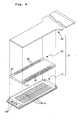
Fig. 4 shows an exploded perspective view illustrating
the head unit 63 as viewed from an upper position.
Fig. 5 shows a bottom view illustrating the head unit
63.
Fig. 6 shows an exploded perspective view illustrating a
piezoelectric ink-jet head 6.
Fig. 7 shows a side sectional view illustrating the
piezoelectric ink-jet head 6.
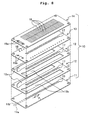
Fig. 8 shows an exploded perspective view illustrating a
cavity plate 10.
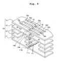
Fig. 9 shows an exploded perspective view illustrating
magnified main components of the cavity plate 10.
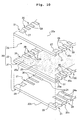
Fig. 10 shows an exploded perspective view illustrating
magnified main components of a piezoelectric actuator 20.
Fig. 11 shows a magnified sectional view illustrating
main components of the piezoelectric ink-jet head 6 shown in
Fig. 7.
Fig. 12 shows a horizontal sectional view taken along a
line A-A' shown in Fig. 11.
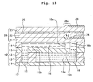
Fig. 13 shows a magnified sectional view illustrating
the operation of the piezoelectric ink-jet head 6.
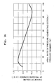
Fig. 14 shows a relationship between the areal ratio of
pressure-generating section/pressure chamber and the change
of volume of the pressure chamber.
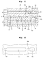
Fig. 15 shows a magnified sectional view illustrating a
situation in which ink droplets are jetted by the
piezoelectric ink-jet head 6.
Fig. 16 shows a magnified sectional view illustrating
the operation of a piezoelectric ink-jet head according to
another embodiment.
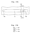
Fig. 17A shows a plan view illustrating a pressure
chamber according to still another embodiment, and Fig. 17B
shows a sectional view taken along a line B-B'.
Fig. 18 shows an exploded perspective view illustrating
a piezoelectric ink-jet head 106.
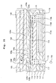
Fig. 19 shows a side sectional view illustrating the
piezoelectric ink-jet head 106.
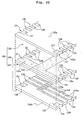
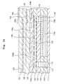
Fig. 20 shows an exploded perspective view illustrating
a cavity plate 110.
Fig. 21 shows an exploded perspective view illustrating
magnified main components of the cavity plate 110.
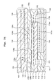
Fig. 22 shows an exploded perspective view illustrating
magnified main components of a piezoelectric actuator 120.
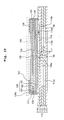
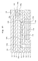
Fig. 23 shows a magnified sectional view illustrating
the piezoelectric ink-jet head 106 shown in Fig. 19.
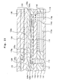
Fig. 24 shows a magnified sectional view illustrating
the operation of the piezoelectric ink-jet head 106.
Fig. 25 shows a magnified sectional view illustrating a
situation in which ink droplets are jetted by the
piezoelectric ink-jet head 106.
Fig. 26 shows a magnified sectional view illustrating
the operation of a piezoelectric ink-jet head according to
another embodiment.
Fig. 27 shows a magnified sectional view illustrating a
piezoelectric ink-jet head according to still another
embodiment.
Fig. 28 shows a magnified sectional view illustrating a
conventional piezoelectric ink-jet head.
DESCRIPTION OF THE PREFERRED EMBODIMENTS
Specified embodiments of the present invention will
be explained with reference to the drawings. However, the
present invention is not limited thereto.
First Embodiment
An explanation will be made below on the basis of
the accompanying drawings about an embodiment in which the
droplet-jetting device of the present invention is applied to
an ink-jet head. Fig. 1 shows a perspective view
illustrating a schematic structure of a color ink-jet printer
which carries the ink-jet head of the present invention. As
shown in Fig. 1, the ink-jet printer 100 comprises ink
cartridges 61 which are filled with four color inks of, for
example, cyan, magenta, yellow, and black, a head unit 63
which is provided with piezoelectric ink-jet heads 6 for
performing the printing on printing paper 62 to be fed in the
direction of the arrow B in Fig. 1, a carriage 64 on which
the ink cartridges 61 and the head unit 63 are carried, a
drive unit 65 which allows the carriage 64 to make
reciprocating movement in a direction perpendicular to the
feeding direction of the printing paper 62, a platen roller
66 which extends in the direction of the reciprocating
movement of the carriage 64 and which is arranged opposingly
to the piezoelectric ink-jet heads 6, and a purge device 67.
The drive unit 65 includes a carriage shaft 71
which is arranged at the lower end of the carriage 64 and
which extends in parallel to the platen roller 66, a guide
plate 72 which is arranged at the upper end of the carriage
64 and which extends in parallel to the carriage shaft 71,
two pulleys 73, 74 which are disposed between the carriage
shaft 71 and the guide plate 72 and which are arranged at the
both ends of the carriage shaft 71, and an endless belt 75
which is stretched between the pulleys 73, 74. When one
pulley 73 is rotated clockwise/counterclockwise in accordance
with the driving of a motor 76, the carriage 64, which is
joined to the endless belt 75, is allowed to make
reciprocating movement in the linear direction along the
carriage shaft 71 and the guide plate 72 in accordance with
the clockwise/counterclockwise rotation of the pulley 73.
The printing paper 62 is fed from an unillustrated
paper feed cassette which is provided on the side of the
color ink-jet printer 100. The printing paper 62 is
introduced into the space between the piezoelectric ink-jet
heads 6 and the platen roller 66, and the predetermined
printing operation is performed thereon with the inks
discharged from the piezoelectric ink-jet heads 6. After
that, the printing paper 62 is discharged. A paper feed
mechanism and a paper discharge mechanism for the printing
paper 62 are omitted from the illustration in Fig. 1.
The purge device 67 is provided on the side of the
platen roller 66. The purge device 67 is arranged so that
the purge device 67 is opposed to the piezoelectric ink-jet
heads 6 when the head unit 63 is disposed at the reset
position. The purge device 67 includes a cap 81 which makes
abutment against an opening surface so that a plurality of
nozzles 15 of the piezoelectric ink-jet head 6 are covered
therewith as described later on, a pump 82, a cam 83, and an
ink storage section 84. When the head unit 63 is disposed at
the reset position, the nozzles 15 of the piezoelectric ink-jet
head 6 are covered with the cap 81. Any defective ink
containing bubbles or the like remaining in the piezoelectric
ink-jet head 6 is aspirated by the pump 82 in accordance with
the driving of the cam 83 in order to restore the
piezoelectric ink-jet head 6 thereby. Accordingly, it is
possible to avoid, for example, any discharge failure caused,
for example, by the growth of bubbles and the residence of
the ink which would possibly occur during the initial
introduction of the ink. The aspirated defective ink is
stored in the ink storage section 84.
Next, the structure of the head unit 63 will be
explained with reference to Figs. 2 to 5. Fig. 2 shows a
perspective view illustrating a state in which the head unit
63 is inverted upside down. Fig. 3 shows an exploded
perspective view illustrating the head unit 63 shown in Fig.
2. Fig. 4 shows an exploded perspective view illustrating
the head unit 63 as viewed from an upper position. Fig. 5
shows a bottom view illustrating the head unit 63.
As shown in Figs. 2 to 5, the head unit 63, which
is carried on the carriage 64 that travels along the printing
paper 62, is formed to have a substantially box-shaped
configuration with its open upper surface. The head unit 63
has a cartridge-carrying section 3 to which the four ink
cartridges 61 can be detachably installed from upper
positions thereof. Ink supply passages 4a, 4b, 4c, 4d, which
are connectable to ink release sections (not shown) of the
respective ink cartridges 61, are disposed at a side portion
3a of the cartridge-carrying section 3 to make communication
down to the lower surface of the bottom plate 5 of the head
unit 63. Packings made of rubber or the like (not shown),
which are capable of making tight contact with the ink
release sections (not shown) of the respective ink cartridges
61, are arranged on the upper surface of the side portion 3a
of the cartridge-carrying section 3.
The bottom plate 5 is formed horizontally while
protruding by one step from the cartridge-carrying section 3.
As shown in Figs. 3 and 5, two support sections 8, which are
provided to arrange the two piezoelectric ink-jet heads 6 in
parallel, are formed in a stepped form on the side of the
lower surface of the bottom plate 5. A plurality of hollow
spaces 9a, 9b, which are provided to effect fixation with UV-curable
adhesive, are formed for the respective support
sections 8 to make penetration in the vertical direction.
Communicating sections 46a, 46b, 46c, 46d, which
make communication with the ink cartridges 61 via the ink
supply passages 4a to 4d, are provided at first ends of the
respective support sections 8. Fitting grooves 48, which
are, for example, 8-shaped as viewed in the plan view, are
recessed at the outer circumferences of the communicating
sections 46a to 46d. Ring-shaped packings 47 made of rubber
or the like are inserted into the fitting grooves 48. When
the piezoelectric ink-jet heads 6 are adhered and fixed to
the support sections 8, then the tips of the packings 47 are
pressed against the outer circumferences of ink supply ports
19a (see Fig. 8) of the piezoelectric ink-jet heads 6 as
described later on, and the portions of abutment against the
ink supply ports 19a are tightly closed.
A protecting cover 44, which is provided to protect
the adhered and fixed piezoelectric ink-jet heads 6, is
attached to cover the bottom plate 5 to which the
piezoelectric ink-jet heads 6 are fixed. The protecting
cover 44 has two elliptic openings which are provided in the
longitudinal direction of the protecting cover 44 so that the
nozzles 15 of the piezoelectric ink-jet heads 6 are exposed.
The protecting cover 44 has both ends in the longitudinal
direction which are folded in a substantially ]-shaped
(angular U-shaped) configuration. Flexible flat cables 40 of
the piezoelectric ink-jet heads 6 are fixed while being
folded in the upward direction of the head unit 63 to extend
along the folding lines when the protecting cover 44 is
fixed.
Next, the structure of the piezoelectric ink-jet
head 6 will be explained with reference to Figs. 6 to 10.
Fig. 6 shows an exploded perspective view illustrating the
piezoelectric ink-jet head 6. Fig. 7 shows a side sectional
view illustrating the piezoelectric ink-jet head 6. Fig. 8
shows an exploded perspective view illustrating a cavity
plate 10. Fig. 9 shows an exploded perspective view
illustrating magnified main components of the cavity plate
10. Fig. 10 shows an exploded perspective view illustrating
magnified main components of a piezoelectric actuator 20.
As shown in Figs. 6 and 7, the piezoelectric ink-jet
head 6 is constructed by laminating and joining, with an
adhesive, the stacked type cavity plate 10 which is composed
of a plurality of sheets, the plate type piezoelectric
actuator 20 which is adhered and stacked onto the cavity
plate 10 by the aid of the adhesive or an adhesive sheet, and
the flexible flat cable 40 which is disposed on the upper
surface of the piezoelectric actuator 20 in order to effect
electric connection to an external apparatus. The ink is
jetted downwardly from the nozzles 15 which are open on the
lower surface side of the cavity plate 10 disposed at the
lowermost layer.
On the other hand, as shown in Fig. 8, the cavity
plate 10 has such a structure that five thin metal plates,
i.e., a nozzle plate 11, two manifold plates 12, a spacer
plate 13, and a base plate 14 are superimposed and stacked
with an adhesive respectively. In the embodiment of the
present invention, each of the plates 11 to 14 is made of
42 % nickel alloy steel plate (42 alloy) having a thickness
of about 50 µm to 150 µm. Each of the plates 11 to 14 may be
formed of, for example, a resin without being limited to the
metal.
As shown in Fig. 9, a plurality of pressure
chambers 16, each of which has a thin width and which extend
in a direction perpendicular to center lines 14a, 14b in the
longitudinal direction, are bored through the base plate 14
in two arrays of zigzag arrangement. Ink supply holes 16b
are bored at positions located outwardly from the respective
pressure chambers 16 toward the both ends of the base plate
14 in the transverse direction of the base plate 14
respectively corresponding to the respective pressure
chambers 16. The respective pressure chambers 16 and the
respective ink supply holes 16b are connected to one another
by throttle sections 16d which are formed therebetween. The
respective ink supply holes 16b are communicated with common
ink chambers 12a, 12b of the manifold plates 12 via
respective ink supply holes 18 which are bored through left
and right portions on the both sides in the transverse
direction of the spacer plate 13. In this embodiment, as
shown in Fig. 12, the throttle section 16d is formed such
that the spacing distance between left and right walls (walls
for constituting connecting sections 16e as described later
on) of the base plate 14 for constituting the throttle
section is smaller than the spacing distances between left
and right walls for constituting the pressure chamber 16 and
the ink supply hole 16b, for the following reason. That is,
it is intended to increase the flow passage resistance to the
counterflow toward the ink supply hole 16b during the ink-jetting
operation as described later on by decreasing the
cross-sectional area of the throttle section 16d in the
direction perpendicular to the direction of the flow of the
ink. First ends 16a of the respective pressure chambers 16
are communicated with the nozzles 15 disposed in the zigzag
arrangement in the nozzle plate 11, via through-holes 17 each
having a minute diameter bored in the zigzag arrangement as
well through the spacer plate 13 and the two manifold plates
12.
As shown in Fig. 8, the ink supply holes 19a, 19b,
which are provided to supply the inks from the ink cartridges
61 to the common ink chambers 12a, 12b of the manifold plates
12, are bored through the base plate 14 and the spacer plate
13 respectively. The two manifold plates 12 are provided
with the two common ink chambers 12a, 12b which extend in the
longitudinal direction while interposing the arrays of the
plurality of nozzles 15 of the nozzle plate 11. The common
ink chambers 12a, 12b are formed as openings which penetrate
through the respective manifold plates 12. One common ink
chamber is formed by the openings which are superimposed in
the vertical direction. One common ink chamber 12a is
communicated with the pressure chambers 16 disposed in one
array, and the other common ink chamber 12b is communicated
with the pressure chambers 16 disposed in the other array.
The respective common ink chambers 12a, 12b are positioned in
the plane parallel to the plane formed by the plurality of
pressure chambers 16 of the base plate 14. Further, the
respective common ink chambers 12a, 12b are formed to extend
by longer distances in the direction of the arrays formed by
the plurality of pressure chambers 16 on the side of the
nozzle plate 11 as compared with the plurality of pressure
chambers 16.
The common ink chambers 12a, 12b are structured
such that they are tightly closed by stacking the nozzle
plate 11 and the spacer plate 13 on the two manifold plates
12. The portion 13a of the spacer plate 13, which forms the
bottom of each of the pressure chambers 16, forms the upper
surface of each of the common ink chambers 12a, 12b. The
portion 13a of the spacer plate 13 is bendable toward each of
the common ink chambers 12a, 12b owing to the resilience.
The plurality of nozzles 15 for jetting the inks,
each of which has a minute diameter (about 25 µm in this
embodiment), are bored through the nozzle plate 11 in the
zigzag arrangement at spacing distances of minute pitches P1
along center lines 11a, 11b in the longitudinal direction of
the nozzle plate 11. The respective nozzles 15 correspond to
respective through-holes 17 bored through the manifold plates
12.
The cavity plate 10 is constructed as described
above. Accordingly, the ink, which inflows into each of the
common ink chambers 12a, 12b from the ink cartridge 61 via
each of the ink supply holes 19a, 19b bored at the first ends
of the base plate 14 and the spacer plate 13, passes from
each of the common ink chambers 12a, 12b through the
respective ink supply holes 18, the respective ink supply
holes 16b, and the throttle sections 16d, and the ink is
distributed to the respective pressure chambers 16. The ink
flows in the direction toward the first ends 16a of the
respective pressure chambers 16. The ink passes through the
respective through-holes 17, and it arrives at the nozzles 15
corresponding to the respective pressure chambers 16.
On the other hand, as shown in Fig. 10, the
piezoelectric actuator 20 is structured such that two
piezoelectric sheets 21, 22 and one insulating sheet 23 are
stacked. A plurality of driving electrodes 24, each of which
has a thin width and which correspond to the respective
pressure chamber 16 of the cavity plate 10 one by one, are
provided in the zigzag arrangement on the upper surface of
the piezoelectric sheet 21 disposed at the lowermost level.
First ends 24a of the respective driving electrodes 24 are
formed to be exposed to left and right side surfaces 20c
which are perpendicular to front and back surfaces 20a, 20b
of the piezoelectric actuator 20.
A common electrode 25, which is common to the
plurality of pressure chambers 16, is provided on the upper
surface of the piezoelectric sheet 22 disposed at the next
level. First ends 25a of the common electrode 25 are also
formed to be exposed to the left and right side surfaces 20c
in the same manner as the first ends 24a of the respective
driving electrodes 24. As shown in Fig. 11, respective
regions of the piezoelectric sheet 22, i.e., pressure-generating
sections 28a, which are interposed between the
respective driving electrodes 24 and the common electrode 25,
are subjected to the polarization treatment in a direction
directed from the driving electrodes 24 to the common
electrode 25. The pressure-generating sections 28a are
connected to the portions 13a of the spacer plate 13 disposed
at the bottoms of the pressure chambers 16 via the walls on
the both sides of the respective throttle sections 16d, i.e.,
the connecting sections 16e. In other words, the pressure-generating
sections 28a are provided only at the positions
corresponding to the connecting sections 16e. This
embodiment is constructed such that the area occupied by the
pressure-generating sections 28a is about 20 % of the area
occupied by the pressure chambers 16.
Surface electrodes 26 corresponding to the
respective driving electrodes 24 one by one and surface
electrodes 27 corresponding to the common electrode 25 are
provided on the upper surface of the insulating sheet 23
disposed at the uppermost level so that the surface
electrodes 26, 27 are aligned along the left and right side
surfaces 20c. First recessed grooves 30 are provided for the
first ends 24a of the respective driving electrodes 24 and
second recesses grooves 31 are provided for the first ends
25a of the common electrode 25 so that the first and second
recessed grooves 30, 31 extend in the stacking direction on
the left and right side surfaces 20c respectively. As shown
in Fig. 7, a side surface electrode 32, which electrically
connects each of the driving electrodes 24 and each of the
surface electrodes 26, is formed in each of the first
recessed grooves 30. Further, a side surface electrode 33,
which electrically connects the common electrode 25 and each
of the surface electrodes 27, is formed in each of the second
recessed grooves 31. Electrodes designated by reference
numerals 28 and 29 are electrodes of extra patterns.
The size of the main components constructing the
piezoelectric actuator of the present embodiment is indicated
as below.
Length of the pressure chamber 16 (in the direction
perpendicular to 14a): 3.7 mm
Width of the pressure chamber 16 (in the direction
parallel to 14a): 0.13 mm
Depth of the pressure chamber 16 (the thickness of the
base plate): 0.05 mm
Width of the driving electrode 24: 0.1 mm
Thickness of the piezoelectric sheets 21, 22: 0.03 mm
Diameter of the nozzle 15: 0.025 mm
Next, the operation of the piezoelectric ink-jet
head 6 will be explained. Fig. 11 shows a magnified
sectional view illustrating main components of the
piezoelectric ink-jet head 6 shown in Fig. 7. As shown in
Fig. 11, the common ink chamber 12a and the pressure chamber
16 are filled with the ink.
As shown in Fig. 13, when a positive voltage is
applied to an arbitrary driving electrode 24 of the
respective driving electrodes 24 of the piezoelectric
actuator 20 of the piezoelectric ink-jet head 6, and the
common electrode 25 is connected to the ground, then the
electric field E is generated between the electrodes in the
direction which is coincides with the direction of
polarization P, and the pressure-generating section 28a is
elongated in the stacking direction owing to the
piezoelectric vertical effect. The pressure-generating
section 28a was elongated in the stacking direction by 20 x
10-6 mm.
The elongation causes the pushing action on the
portion 13a of the spacer plate 13 which forms the bottom of
the pressure chamber 16 toward the common ink chamber 12a via
the connecting section 16e. The portion 13a is displaced
about the support point of the fixed portion 13b formed
between the spacer plate 13 and the manifold plate 12 in the
vicinity of the through-hole 17. It was found out that by
the displacement of the portion 13a, the volume of the
pressure chamber was increased by 3.98 x 10⁻⁶ mm3. Further,
in the piezoelectric actuator of the conventional structure
as shown in Fig. 28, when the pressure-generating section
228a had the same area as that of the pressure-generating
section 28a shown in Fig. 13, the volume of the pressure
chamber was decreased by 1.70 x 10⁻⁶ mm3 by the elongation of
the pressure-generating section 228a in the stacking
direction. Namely, owing to the provision of the connecting
section 16e, the piezoelectric actuator of the present
invention has realized a pull-eject in which the change of
volume is relatively large. Further, it is noted that when
the pressure-generating section 28a is elongated, the
displacement of the connecting section 16e does not directly
influence the change of volume of the pressure chamber, and
the connecting section 16e displaces the portion 13a to
indirectly change the volume of the pressure chamber.
Fig. 14 shows a relationship between the areal
ratio of pressure-generating section/pressure chamber and the
change of the volume of the pressure chamber. As shown in
Fig. 14, if the area of the pressure-generating section 28a
exceeds about 60 % with respect to the pressure chamber 16,
the volume of the pressure chamber 16 is changed to cause the
decrease. In this case, the jetting method, which is so-called
the push-eject, is performed. On the contrary, when
the area of the pressure-generating section 28a is smaller
than about 60 % with respect to the pressure chamber 16, the
volume of the pressure chamber 16 is changed to cause the
increase. In other words, a volumetric change of the
pressure chamber 16 caused by displacement of the portion 13a
is greater than that caused directly by displacement of the
pressure-generating section 28a. Therefore, it is possible
to perform the so-called pull-eject in which the volume of
the pressure chamber 16 is firstly increased and then the
volume is restored to the original volume. As clarified from
Fig. 14, when the pressure-generating section 28a is set to
5 % to 40 % with respect to the pressure chamber 16, it is
possible to obtain the volume change in order to jet the ink
droplets having necessary volumes by means of the pull-eject.
Further, when the area of the pressure-generating section 28a
is about 10 % to 20 % of the area of the pressure chamber,
then the volume change of the pressure chamber 16 can be
increased to be not less than 0.9 x 10⁻⁴, and it is possible
to obtain the sufficient performance. The area of the
pressure-generating section means an area of the pressure-generating
section interposed between the driving electrode
24 and the common electrode 25 in the piezoelectric actuator
20. The area of the pressure chamber is an area of the
pressure chamber 16 except for the both ends (the first ends
16a, the throttle sections 16d, the ink supply holes 16b),
and means an area of the wall surface which defines the
pressure chamber and which is displaceable in a direction in
which a volume of the pressure chamber is varied.
The state, in which the volume of the pressure
chamber 16 is expanded, is maintained by a period of one-way
transmission time T of the generated pressure wave in the
pressure chamber 16. By doing so, the ink, which corresponds
to the increased volume of the pressure chamber 16, is
supplied during the period of time from the common ink
chamber 12a via the ink supply hole 18, the ink supply hole
16, and the throttle section 16d.
The one-way transmission time T is the time which
is necessary for the pressure wave in the pressure chamber 16
to be transmitted in the longitudinal direction of the
pressure chamber 16 (in the lateral direction on the plane of
the drawing paper). The one-way transmission time T is
determined as T = L/a by the length L of the pressure chamber
16 and the acoustic velocity "a" in the ink in the pressure
chamber 16. According to the pressure wave transmission
theory, when an approximate period of time T elapses from the
application of the voltage, then the pressure in the pressure
chamber 16 is inverted, and the pressure is changed to the
positive pressure. When the application of the voltage is
stopped in conformity with this timing, then the pressure-generating
section 28a is contracted to the original state as
shown in Fig. 15, and the volume of the expanded pressure
chamber 16 is restored to the original volume. Therefore,
the pressure is applied to the ink contained in the pressure
chamber 16. In this situation, the pressure having been
changed to the positive and the pressure generated by the
disappearance of strain of the pressure-generating section
28a are added to one another, and a relatively high pressure
is generated at a portion in the vicinity of the nozzle 15
communicating with the pressure chamber 16. Accordingly, the
ink droplets 90 are jetted from the nozzle 15 efficiently as
compared with the simple push-eject.
As explained above, in the piezoelectric ink-jet
head 6 according to the embodiment of the present invention,
the area of the pressure-generating section 28a is
established within the range of not less than 5 % and not
more than 40 % as compared with the area of the pressure
chamber 16. Therefore, the pressure chamber 16 is expanded
by the volume change brought about by the displacement of the
pressure-generating section 28a. Further, the connecting
section 16e, which serves to transmit the displacement of the
pressure-generating section 28a to the bottom surface portion
of the pressure chamber 16, is provided between the pressure-generating
section 28a and the bottom surface of the pressure
chamber 16. Therefore, the elongation displacement of the
pressure-generating section 28a depresses the bottom surface
of the pressure chamber 16 via the connecting section 16e
during the application of the voltage, making it easy to
perform the pull-eject which is advantageous to achieve the
high driving frequency and jet the ink droplets having large
volumes. Further, the displacement is caused over the wide
area of the pressure chamber 16 by means of the displacement
over the small area of the pressure-generating section 28a.
Therefore, it is possible to decrease the area of the
pressure-generating section 28a, and it is possible to reduce
the electrostatic capacity possessed by the pressure-generating
section 28a. When the throttle section 16d is
provided for the connecting section 16e, it is unnecessary to
increase the number of parts.
The present invention is not limited to the
embodiment described above, which may be embodied in other
various forms of improvements and modifications. For
example, the number of pressure-generating section or
pressure-generating sections is not limited to one for one
pressure chamber. Fig. 16 shows a magnified sectional view
illustrating the operation of a piezoelectric ink-jet head
according to another embodiment. As shown in Fig. 16, two
pressure-generating sections 28b, 28c each having a small
area may be arranged for one pressure chamber 16, and
connecting sections 16e may be provided at two portions
corresponding to the pressure-generating sections 28b, 28c
respectively. Further, as shown in Fig. 17, the following
configuration may be also available. That is, a pressure
chamber 16 has a substantially uniform width ranging to an
ink supply hole 16b, and a connecting section 16e is
connected to the base plate 14 via a thin-walled section 16f.
In this arrangement, a throttle section 16d is formed by the
thin-walled section 16f.
Second Embodiment
Another embodiment of the droplet-jetting device
according to the present invention will be explained with
reference to Figs. 12 to 27. The droplet-jetting device of
this embodiment is constructed in the same manner as in the
first embodiment except that the structure of the
piezoelectric ink-jet head is changed.
At first, the structure of a piezoelectric ink-jet
head 106 will be explained with reference to Figs. 18 to 22.
Fig. 18 shows an exploded perspective view illustrating the
piezoelectric ink-jet head 106. Fig. 19 shows a side
sectional view illustrating the piezoelectric ink-jet head
106. Fig. 20 shows an exploded perspective view illustrating
a cavity plate 110. Fig. 21 shows an exploded perspective
view illustrating magnified main components of the cavity
plate 110. Fig. 22 shows an exploded perspective view
illustrating magnified main components of a piezoelectric
actuator 120.
As shown in Figs. 18 and 19, the piezoelectric ink-jet
head 106 is constructed by laminating and joining, with
an adhesive, the stacked type cavity plate 110 which is
composed of a plurality of sheets, the plate type
piezoelectric actuator 120 which is adhered and stacked onto
the cavity plate 110 by the aid of the adhesive or an
adhesive sheet with a vibration plate 129a intervening
therebetween, and a flexible flat cable 140 which is disposed
on the upper surface of the piezoelectric actuator 120 in
order to effect electric connection to an external apparatus.
The ink is jetted downwardly from nozzles 115 which are open
on the lower surface side of the cavity plate 110 disposed at
the lowermost layer.
On the other hand, as shown in Fig. 20, the cavity
plate 110 has such a structure that five thin metal plates,
i.e., a nozzle plate 111, two manifold plates 112, a spacer
plate 113, and a base plate 114 are superimposed and stacked
with an adhesive respectively. In the embodiment of the
present invention, each of the plates 111 to 114 is made of
42 % nickel alloy steel plate (42 alloy) having a thickness
of about 50 µm to 150 µm. Each of the plates 111 to 114 may
be formed of, for example, a resin without being limited to
the metal.
As shown in Fig. 21, a plurality of pressure
chambers 116, each of which has a thin width and which extend
in a direction perpendicular to center lines 114a, 114b in
the longitudinal direction, are bored through the base plate
114 in zigzag arrangement. Ink supply holes 116b are bored
at positions located outwardly from the respective pressure
chambers 116 toward the both ends of the base plate 114 in
the transverse direction of the base plate 114 respectively
corresponding to the respective pressure chambers 116. The
respective pressure chambers 116 and the respective ink
supply holes 116b are connected to one another by throttle
sections 116d which are formed therebetween. The respective
ink supply holes 116b are communicated with common ink
chambers 112a, 112b of the manifold plates 112 via respective
ink supply holes 118 which are bored through left and right
portions on the both sides in the transverse direction of the
spacer plate 113. In this structure, the cross-sectional
area of each of the throttle sections 116d in the direction
perpendicular to the direction in which the ink flows is
smaller than the cross-sectional area of each of the pressure
chambers 116 in the same direction, for the following reason.
That is, it is intended to increase the flow passage
resistance to the counterflow of the ink toward the ink
supply hole 116b during the jetting operation. First ends
116a of the respective pressure chambers 116 are communicated
with the nozzles 115 disposed in the zigzag arrangement in
the nozzle plate 111, via through-holes 117 each having a
minute diameter bored in the zigzag arrangement as well
through the spacer plate 113 and the two manifold plates 112.
As shown in Fig. 20, the ink supply holes 119a,
119b, which are provided to supply the inks from the ink
cartridges (61) to the common ink chambers 112a, 112b of the
manifold plates 112, are bored through the base plate 114 and
the spacer plate 113 respectively. The two manifold plates
112 are provided with the two common ink chambers 112a, 112b
which extend in the longitudinal direction while interposing
the arrays of the plurality of nozzles 115 of the nozzle
plate 111. The common ink chambers 112a, 112b are formed as
openings which penetrate through the respective manifold
plates 112. One common ink chamber is formed by the openings
which are superimposed in the vertical direction. One common
ink chamber 112a is communicated with the pressure chambers
disposed in one array, and the other common ink chamber 112b
is communicated with the pressure chambers disposed in the
other array (see Fig. 21). The common ink chambers 112a,
112b are positioned in the plane parallel to the plane formed
by the plurality of pressure chambers 116 of the base plate
114. Further, the common ink chambers 112a, 112b are formed
to extend by longer distances in the direction of the arrays
formed by the plurality of nozzles 115 on the side of the
opening surface of the plurality of nozzles 115 of the nozzle
plate 111 as compared with the plurality of pressure chambers
116.
The common ink chambers 112a, 112b are shaped such
that the cross-sectional areas are decreased at certain
proportions in directions to make separation from the ink
supply holes 119a, 119b at the ends (C portions) separated
from the ink supply holes 119a, 119b, for the following
reason. That is, it is intended to facilitate the discharge
of remaining bubbles which are apt to stay at the ends (C
portions) of the common ink chambers 112a, 112b. The common
ink chambers 112a, 112b are structured such that they are
tightly closed by stacking the nozzle plate 111 and the
spacer plate 113 on the two manifold plates 112.
The plurality of nozzles 115 for jetting the inks,
each of which has a minute diameter (about 25 µm in this
embodiment), are bored through the nozzle plate 111 in the
zigzag arrangement at spacing distances of minute pitches P2
along center lines 111a, 111b in the longitudinal direction
of the nozzle plate 111. The respective nozzles 115
correspond to respective through-holes 117 bored through the
manifold plates 112.
The cavity plate 110 is constructed as described
above. Accordingly, the ink, which inflows into each of the
common ink chambers 112a, 112b from the ink cartridge (61)
via each of the ink supply holes 119a, 119b bored at the
first ends of the base plate 114 and the spacer plate 113,
passes from each of the common ink chambers 112a, 112b
through the respective ink supply holes 118, the respective
ink supply holes 116b, and the throttle sections 116d, and
the ink is distributed to the respective pressure chambers
116. The ink flows in the direction toward the first ends
116a of the respective pressure chambers 116. The ink passes
through the respective through-holes 117, and arrives at the
nozzles 115 corresponding to the respective pressure chambers
116.
On the other hand, as shown in Fig. 22, the
piezoelectric actuator 120 is structured such that two
piezoelectric sheets 121, 122 and one insulating sheet 123
are stacked. A plurality of driving electrodes 124, each of
which has a thin width and which correspond to the respective
pressure chamber 116 of the cavity plate 110 one by one, are
provided in the zigzag arrangement on the upper surface of
the piezoelectric sheet 121 disposed at the lowermost level.
First ends 124a of the respective driving electrodes 124 are
formed to be exposed to left and right side surfaces 120c
which are perpendicular to front and back surfaces 120a, 120b
of the piezoelectric actuator 120.
A common electrode 125, which is common to the
plurality of pressure chambers 116, is provided on the upper
surface of the piezoelectric sheet 122 disposed at the next
level. First ends 125a of the common electrode 125 are also
formed to be exposed to the left and right side surfaces 120c
in the same manner as the first ends 124a of the respective
driving electrodes 124. Respective regions of the
piezoelectric sheet 122, which are interposed between the
respective driving electrodes 124 and the common electrode
125, serve as pressure-generating sections 128a corresponding
to the respective pressure chambers 116 one by one. The
pressure-generating sections 128a are subjected to the
polarization treatment in a direction P directed from the
driving electrodes 124 to the common electrode 125. This
embodiment is constructed such that the area occupied by the
pressure-generating sections 128a is about 10 % of the area
occupied by the pressure chambers 116.
Surface electrodes 126 corresponding to the
respective driving electrodes 124 one by one and surface
electrodes 127 corresponding to the common electrode 125 are
provided on the upper surface of the insulating sheet 123
disposed at the uppermost level so that the surface
electrodes 126, 127 are aligned along the left and right side
surfaces 120c. First recessed grooves 130 are provided for
the first ends 124a of the respective driving electrodes 124
and second recesses grooves 131 are provided for the first
ends 125a of the common electrode 125 so that the first and
second recessed grooves 130, 131 extend in the stacking
direction on the left and right side surfaces 120c
respectively. As shown in Fig. 19, a side surface electrode
132, which electrically connects each of the driving
electrodes 124 and each of the surface electrodes 126, is
formed in each of the first recessed grooves 130. Further, a
side surface electrode 133, which electrically connects the
common electrode 125 and each of the surface electrodes 127,
is formed in each of the second recessed grooves 131.
Electrodes designated by reference numerals 128 and 129 are
electrodes of extra patterns.
On the other hand, Fig. 23 shows a magnified
sectional view illustrating the piezoelectric ink-jet head
106 shown in Fig. 19. Fig. 23 shows a state in which the
common ink chamber 112a and the pressure chamber 116 are
filled with the ink. As shown in Fig. 23, the vibration
plate 129a is arranged between the piezoelectric actuator 120
and the cavity plate 110. The vibration plate 129a has three
space sections 129d, 129f, 129g which are formed as recesses
by means of, for example, the half etching so that the space
sections 129d, 129f, 129g are aligned in the longitudinal
direction of the pressure chamber 116 on the side to make
contact with the piezoelectric actuator 120. A projection
129e, which is disposed between the space sections 129g,
129d, is secured to the piezoelectric actuator 120 while
making abutment thereagainst. The projection 129e serves as
a support point section when the vibration plate 129a is
displaced as described later on. A portion of the vibration
plate 129a, which corresponds to a region ranging from the
space section 129g disposed on one side of the projection
129e to the space section 129f, serves as a first deformable
section 129b. A portion of the vibration plate 129a, which
is interposed between the pressure chamber 116 and the space
section 129d disposed on the other side of the projection
129e, serves as a second deformable section 129c. The first
deformable section 129b is opposed to the pressure-generating
section 128a of the piezoelectric actuator 120 via a
projection 129h intervening therebetween. The first
deformable section 129b and the second deformable section
129c are positioned corresponding to the pressure chamber
116. The tip of the second deformable section 129c does not
arrive at the throttle section 116d. The length of the first
deformable section 129b in the longitudinal direction of the
pressure chamber 116 is shorter than the length of the second
deformable section 129c in the longitudinal direction of the
pressure chamber 116. It is enough that the respective space
sections 129d, 129f, 129g are formed to successfully secure
the first deformable section 129b, the second deformable
section 129c, and the projection 129e. They may be formed by
arranging and stacking a bored plate on the piezoelectric
actuator 120 and a non-bored plate on the side of the
pressure chamber 116, without being limited to the half
etching.
The size of the main components constructing the
piezoelectric actuator of the present embodiment is indicated
as below.
Next, the operation of the ink-jet printer (100)
during the printing will be explained with reference to Figs.
24 and 25. As shown in Fig. 24, when a positive voltage is
applied to an arbitrary driving electrode 124 of the
respective driving electrodes 124 of the piezoelectric
actuator 120 of the piezoelectric ink-jet head 106, and the
common electrode 125 is connected to the ground, then the
electric field E is generated between the electrodes in the
direction which is coincides with the direction of
polarization P. The portion of the piezoelectric sheet 122
corresponding to the driving electrode 124 to which the
voltage is applied, i.e., the pressure-generating section
128a is elongated in the stacking direction owing to the
piezoelectric vertical effect. The pressure-generating
section 128a is elongated by 20 x 10-6 mm in the stacking
direction.
The elongation causes the pushing action on the
projection 129h so that the first deformable section 129b of
the vibration plate 129a is deformed toward the pressure
chamber 116. Accordingly, the second deformable section 129c
of the vibration plate 129a is deformed about the support
point of the projection 129e in the opposite direction, i.e.,
into the space section 129d on the side of the piezoelectric
actuator 120, and thus the volume of the pressure chamber 116
is expanded. In this arrangement, the length of the first
deformable section 129b in the longitudinal direction of the
pressure chamber 116 is shorter than the length of the second
deformable section 129c in the longitudinal direction of the
pressure chamber 116. Therefore, the amount of increase of
the volume of the pressure chamber 116 brought about by the
second deformable section 129c is much larger than the amount
of decrease of the volume on the side of the pressure chamber
116 brought about by the first deformable section 129b in
accordance with the lever principle. As a result, the volume
of the pressure chamber 116 corresponding to each of the
driving electrodes 124 is greatly expanded, and the pressure
in the pressure chamber 116 is decreased. It was found out
that by the displacement of the first deformable portion
129b, the volume of the pressure chamber 116 was decreased by
3.7 x 10⁻⁶ mm3, and by the displacement of the second
deformable portion 129c, the volume of the pressure chamber
116 is increased by 10.2 x 10⁻⁶ mm3. Further, in the
piezoelectric actuator of the conventional structure as shown
in Fig. 28, when the pressure-generating section 228a had the
same area as that of the pressure-generating section 128a
shown in Fig. 23, the volume of the pressure chamber was
decreased by 0.851 x 10⁻⁶ mm3 by the elongation of the
pressure-generating section 228a in the stacking direction.
Namely, owing to the provision of the first and the second
deformable sections, the piezoelectric actuator of the
present invention has realized a pull-eject in which the
change of volume is relatively large.
The state, in which the volume of the pressure
chamber 116 is expanded, is maintained by a period of one-way
transmission time T of the generated pressure wave in the
pressure chamber 116. By doing so, the ink, which
corresponds to the increased volume of the pressure chamber
116, is supplied during the period of time from the common
ink chamber 112a via the ink supply hole 118, the ink supply
hole 116, and the throttle section 116d.
The one-way transmission time T is the time which
is necessary for the pressure wave in the pressure chamber
116 to be transmitted in the longitudinal direction of the
pressure chamber 116 (in the lateral direction on the plane
of the drawing paper). The one-way transmission time T is
determined as T = L/a by the length L of the pressure chamber
116 and the acoustic velocity "a" in the ink in the pressure
chamber 116. According to the pressure wave transmission
theory, when an approximate period of time T elapses from the
application of the voltage, then the pressure in the pressure
chamber 116 is inverted, and the pressure is changed to the
positive pressure. When the application of the voltage to
the driving electrode 124 is stopped in conformity with this
timing, then the pressure-generating section 128a is restored
to the original state as shown in Fig. 25, and the volume of
the pressure chamber 116 is restored to the original volume
by the second deformable section 129c. Therefore, the
pressure is applied to the ink contained in the pressure
chamber 116. In this situation, the pressure having been
changed to the positive and the pressure generated by the
restoration of the second deformable section 129c are added
to one another, and a relatively high pressure is generated
at a portion in the vicinity of the nozzle 115 communicating
with the pressure chamber 116. Accordingly, the ink droplets
190 are jetted from the nozzle 115 efficiently as compared
with the simple push-eject.
As explained above, in the piezoelectric ink-jet
head 106 according to the embodiment of the present
invention, the vibration plate 129a has the first deformable
section 129b which is deformable toward the pressure chamber
116 and the second deformable section 129c which is
deformable into the space section 129d disposed on the side
opposite to the pressure chamber 116 in accordance with the
displacement of the first deformable section 129b, the first
deformable section 129b and the second deformable section
129c being aligned in the longitudinal direction of the
pressure chamber 116 with the projection 129e as the support
point section intervening therebetween. The first deformable
section 129b is opposed to the pressure-generating section
128a which is elongatable and displaceable in accordance with
the application of the voltage. Therefore, when the voltage
is applied, the elongation of the pressure-generating section
128a deforms the first deformable section 129b toward the
pressure chamber 116 to decrease the volume of the pressure
chamber 116. However, the second deformable section 129c is
displaced into the space section 129d about the support point
of the projection 129e to increase the volume of the pressure
chamber 116. Therefore, the pull-eject, which is
advantageous to achieve the high driving frequency and
perform the large volume jetting operation, can be easily
accomplished by applying the voltage during the jetting
operation. The length of the first deformable section 129b
in the longitudinal direction of the pressure chamber 116 is
shorter than the length of the second deformable section 129c
in the longitudinal direction of the pressure chamber 116.
Therefore, the amount of expansion of the volume of the
pressure chamber 116 brought about by the second deformable
section 129c is larger than the amount of decrease of the
volume on the side of the pressure chamber 116 brought about
by the first deformable section 129b in accordance with the
lever principle. Accordingly, it is possible to decrease the
area of the pressure-generating section 128a necessary to
obtain the desired volume change in the pressure chamber 116.
It is possible to reduce the electrostatic capacity possessed
by the pressure-generating section 128a, and it is possible
to perform the driving operation at a lower voltage.
Further, in the embodiment of the present invention, the
space sections 129f, 129g, 129d are provided, for example, by
means of the half etching so that the projection 129e is
formed therebetween. The support point section is formed
without using any special member, and the effect of the
present invention is realized without complicating the
structure.
In the second embodiment, by making the area of the
pressure-generating section to be not more than 60 % of the
area of the pressure chamber, it is possible to increase the
volume change of the pressure chamber to obtain a sufficient
ink-eject amount. The area of the pressure-generating
section means an area of the pressure-generating section
interposed between the driving electrode 124 and the common
electrode 125 in the piezoelectric actuator 120. The area of
the pressure chamber is an area of the pressure chamber 116
except the both ends (the first ends 116a, the throttle
sections 116d, the ink supply holes 116b), and means an area
of the wall surface which defines the pressure chamber and
which is displaceable in a direction to vary a volume of the
pressure chamber 116.
Fig. 26 shows a magnified sectional view
illustrating the operation of a piezoelectric ink-jet head
according to another embodiment. As shown in Fig. 26, as for
the positional relationship between the first deformable
section and the second deformable section, the first
deformable section 129b may be arranged on the side of the
ink supply hole 118 to supply the ink to the pressure chamber
116. In the same manner as in the embodiment described
above, as shown in Fig. 26, when the voltage is applied, the
elongation in the stacking direction is generated in the
pressure-generating section 128a in accordance with the
piezoelectric vertical effect. The elongation deforms the
first deformable section 129b of the vibration plate 129a
toward the pressure chamber 116 to decrease the volume of the
pressure chamber 116. Accordingly, the second deformable
section 129c is deformed into the space section 129d about
the support point of the projection 129e to expand the volume
of the pressure chamber 116.
Fig. 27 shows a magnified sectional view
illustrating a piezoelectric ink-jet head according to still
another embodiment. In this embodiment, the first deformable
section 129b is not deformed into the pressure chamber 116.
A space section 129g is provided at a portion opposed to the
first deformable section 129b disposed outside the pressure
chamber 116. The vibration plate 129a is provided with no
support point section. A support point section 129i is
provided between the pressure chamber 116 and the space
section 129g. The space section 129g and the support point
section 129i are formed in an aligned manner with the
pressure chamber 116 in the base plate 114. When the voltage
is applied, the elongation in the stacking direction is
generated in the pressure-generating section 128a in
accordance with the piezoelectric vertical effect. The
elongation deforms the first deformable section 129b into the
space section 129g. The volume of the pressure chamber 116
is not decreased at all, because the space section 129g is
disposed outside the pressure chamber 116. The second
deformable section 129c is deformed into the space section
129d about the support point of the support point section
129i. The volume of the pressure chamber 116 is increased in
an amount of the total volume corresponding to the
deformation of the second deformable section 129c.
Therefore, it is possible to expand the volume of the
pressure chamber 116 more efficiently.
The present invention has been explained with
reference to the specified embodiments described above.
However, the present invention is not limited to the
specified embodiments. It is possible to make a variety of
improvements and modifications of the specified embodiments
within a range in which the present invention is not deviated
from the gist or essential characteristics thereof. That is,
it is possible to apply an arbitrary structure provided that
the pressure chamber is expanded by the elongation of the
pressure-generating section toward the pressure chamber in
the structure.
The first object is to provide the droplet-jetting
device in which the electrostatic capacity is suppressed to
improve the energy efficiency and the voltage is applied only
when the device is driven so that the pull-eject is
successfully performed as in the droplet-jetting device of
the present invention. The second object of the present
invention is to provide the droplet-jetting device which
makes it possible to increase the driving frequency and which
makes it possible to increase the volume of the liquid
droplet.