EP1364752B1 - Electric hand tool with several speed ranges - Google Patents
Electric hand tool with several speed ranges Download PDFInfo
- Publication number
- EP1364752B1 EP1364752B1 EP03101261A EP03101261A EP1364752B1 EP 1364752 B1 EP1364752 B1 EP 1364752B1 EP 03101261 A EP03101261 A EP 03101261A EP 03101261 A EP03101261 A EP 03101261A EP 1364752 B1 EP1364752 B1 EP 1364752B1
- Authority
- EP
- European Patent Office
- Prior art keywords
- selector
- switching
- hand tool
- electric hand
- transmission
- Prior art date
- Legal status (The legal status is an assumption and is not a legal conclusion. Google has not performed a legal analysis and makes no representation as to the accuracy of the status listed.)
- Expired - Lifetime
Links
Images

Classifications
-
- B—PERFORMING OPERATIONS; TRANSPORTING
- B25—HAND TOOLS; PORTABLE POWER-DRIVEN TOOLS; MANIPULATORS
- B25F—COMBINATION OR MULTI-PURPOSE TOOLS NOT OTHERWISE PROVIDED FOR; DETAILS OR COMPONENTS OF PORTABLE POWER-DRIVEN TOOLS NOT PARTICULARLY RELATED TO THE OPERATIONS PERFORMED AND NOT OTHERWISE PROVIDED FOR
- B25F5/00—Details or components of portable power-driven tools not particularly related to the operations performed and not otherwise provided for
- B25F5/001—Gearings, speed selectors, clutches or the like specially adapted for rotary tools
Definitions
- the invention relates to a power tool with a mounted in a transmission housing, multi-stage transmission and a switching device for switching the transmission from one gear stage to another gear stage, the spring-loaded, can be brought into several stages slide switch and, actuated by this, on an axial having sliding ratchet wheel acting, resiliently formed switch bracket.
- Power tools of the above type have a, stored in a gearbox, multi-stage gearbox and a switching device for switching the transmission from one gear stage to another gear stage to adjust the speed of a tool used, such as a screwdriver bit or drill to the conditions ,
- From the DE 3 904 085 is a power tool with a gearbox mounted in a multi-stage transmission and with a switching device for switching the transmission from one gear stage to another gear stage, known.
- the transmission has a spring-loaded, can be brought into several stages shift slide and a, actuated by this on an axially sliding ratchet wheel acting, resiliently formed switch bracket.
- An advantage of the known solution is that always a reliable gear change is ensured for switching the transmission.
- a disadvantage of the known solution is that in a transmission with more than two gears more slide valves are necessary.
- US 6,186,709 shows a device for changing the speed of an electric tool. This has a slide switch which is coupled to two switch wires and can be locked in different switch positions. The switching wires attack with their free ends while a speed change device with which the rotational speed of an electric motor can be modified.
- WO 02/059500 and US 2002/0098938 each show a switching device for a power tool with at least three gears. This has switching gears with circumferential grooves, in each of which a jumper wire is inserted. The jumper wires project with their free ends out of the groove, wherein they are displaceable by means of a rotatable shift sleeve along slots which are embedded in a transmission sleeve.
- US 2,911,841 shows a hand tool with a two-speed transmission. This has a two-stage gear block, which is displaceable by means of a shift fork. The shift fork is laterally displaceable along a guide by means of a pivoting lever.
- US 3,934,688 shows a switching device for separating a slip clutch.
- the present invention has for its object to provide an economically producible and handy multi-speed transmission.
- the transmission has a plurality of axially displaceable switching wheels, wherein each ratchet cooperates with a respective shift bracket and the shift bracket by means of the slide switch can be actuated.
- the switching bracket each have a fixedly arranged on the transmission housing, pivot axis to a defined switching position of the switching wheels and thus granted a reliable switching.
- the transmission has more than two gears. Furthermore, all switching elements are actuated by the operation of the slide switch, thereby ensuring a high degree of maneuverability. By an axial displacement of the slide switch a switching of the transmission from one gear stage to another gear stage is assured.
- the spring-trained switching bracket ensure a safe switching, especially when switching the gearbox at a standstill, since the switch bracket bring the corresponding parts of the transmission into engagement, at the latest in a drive of the transmission.
- bearing parts are arranged on the gear housing for guiding the switch bracket, in particular through holes, for receiving the switch bracket in regions. Further, by the pivotal mounting of the switch bracket on the transmission housing by the leverage a force conversion between the force acting on the slide actuator and the force acting on the respective ratchet force is possible, depending on the positioning of the pivot axis on the transmission housing.
- each switching bracket each has at least one engaging part and at least one switching part for switching the corresponding switching wheel, wherein the engaging part cooperates with the corresponding ratchet and the switching member serves as a transmission means of the actuating force from the slide switch to the engaging part.
- the slide switch preferably has at least one recess for supporting the switching part, thereby ensuring a compact design of the transmission.
- a recess is economical to produce and facilitates the final assembly of the transmission.
- the recess is preferably formed transversely to the longitudinal axis of the transmission and substantially tangentially to the switching wheels, to ensure a simple final assembly and secure guidance of the switching part in the slide switch.
- the recess has advantageously in the longitudinal direction of a control link for pivoting the switch bracket to the swivel ash to ensure a structurally simple and economical control of the switch bracket by the slide switch.
- the control link pivots depending on the position of the slide switch individual switching bracket and thereby shifts the corresponding switching bracket corresponding ratchet.
- the switch bracket pass through the recess advantageously with their respective switching part, which acts as a connecting part.
- the recess transversely to the longitudinal axis of the transmission preferably has a height which substantially corresponds to the diameter of the switching part with a game in order to ensure optimum switching.
- the game allows in the manufacture of the transmission a higher tolerance and thereby has a positive economic effect on the manufacturing cost.
- the control link advantageously has two switching stages, wherein different and mutually corresponding switching stages are connected to each other by a ramp.
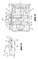
- a transmission 1 of an inventive power tool shown to the working direction A a tool holder 11 for receiving a tool holder, for example, a ringerb itfact anschliesst.
- the transmission 1 has a substantially cylindrically shaped transmission housing 6, which is made for example of plastic or the like, and a switching device for switching the transmission 1 from one gear stage to another gear stage.
- the transmission 1 has a spring-loaded, in three, in particular in Fig. 1a to 3a shown switching stages can be brought on slide switch 3 and a first and second switch bracket 5a, 5b, each acting on a corresponding axially displaceable ratchet wheel 4a, 4b.
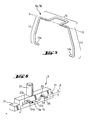
- U-shaped switch bracket 5a, 5b which has a switching part 15 and two engagement parts 14, wherein the two engagement parts 14 each form free ends 14a of the shift yoke 5a, 5b and the switching part 15, the two engagement parts 14 together.
- the free end 14a of the engagement members 14 is angled approximately 90 ° relative to the rest of the engagement member 14, so that the free ends 14a of the shift yoke 5a, 5b are directed against each other and in each case a corresponding recess in the form of an annular groove 4c on which the shift bracket 5a, 5b associated switching wheel 4a, 4b can be brought.
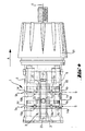
- the two engagement members 14 engage with their free ends 14a, the gear housing 6 by respectively corresponding, diametrically disposed and axially extending longitudinal holes 18.
- the switching bracket 5a, 5b are resilient, for example made of spring steel or similar.
- the gear housing 6, provided with through holes, bearing elements 19a, 19b, which store the switch bracket 5a, 5b about a pivot axis S pivotally mounted on the gear housing 6.
- the switching yokes 5a, 5b pass through the switching part 15 in each case the two corresponding through-holes next to the slide switch.
- Fig. 6 having a substantially cuboid outer contour, slide switch 3 is mounted axially displaceable on the gear housing 6 and has a, transverse to the longitudinal axis L of the transmission 1 and substantially tangential to the switching gears 4a, 4b continuously formed recess, in particular a control link 20.
- the control link 20 extends axially to the transmission 1 and has at the two longitudinal ends in each case a taper 21 for mounting on the transmission housing 6.
- the switching bracket 5a, 5b pass through the control link 20 respectively with the switching member 15 and are pivotally mounted in the control link 20 with respect to the pivot axis S.
- control link 20 has transversely to the longitudinal axis of the transmission to a height h, which substantially corresponds to the diameter of the switching member 15 with a game s.
- control link 20 has two switching stages 22, 23, wherein different and mutually corresponding switching stages 22a, 23a are connected to each other by a ramp 24a.
- the slide switch 3 on the side facing away from the gear housing 6 side surface on an actuating element 25 for setting the slide switch 3.
- the transmission 1 is switchable between three different gears.
- the slide switch 3 is shown with the control link 20, wherein the switching parts 15 are shown in cross section to clearly represent their positions in the control link 20 in the three different gears.
- the Fig. 1a is the transmission 1 in the first gear and the two shift yokes 5a, 5b are perpendicular to the longitudinal axis L of the transmission 1, as this particular Fig. 1b is apparent.
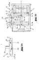
- the slide switch 3 in contrast to the in Fig. 1a and 1b shown displaced in the direction A and the transmission 1 in second gear.
- the switching slide 3 by cross-section of the switching part 15 of the second switching bracket 5b was moved to the second switching stage 23 of the control link 20 and the second switching bracket 5b thereby pivoted about its pivot axis S by an angle ⁇ .
- the pivoting of the switching bracket 5b, in particular of the engaging part 14 leads to an axial movement of the second switching wheel 4b.
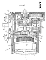
- transmission 1 has two, in the longitudinal direction L of the transmission 1, successively arranged planetary gear, as are well known in the prior art.
Description
Die Erfindung betrifft ein Elektrowerkzeug mit einem, in einem Getriebegehäuse gelagerten, mehrstufigen Getriebe und mit einer Schaltvorrichtung zum Umschalten des Getriebes von einer Getriebestufe in eine andere Getriebestufe, die einen federbeaufschlagten, in mehrere Schaltstufen bringbaren Schaltschieber und einen, von diesem betätigbaren, auf ein axial schiebbares Schaltrad einwirkenden, federnd ausgebildeten Schaltbügel aufweist.The invention relates to a power tool with a mounted in a transmission housing, multi-stage transmission and a switching device for switching the transmission from one gear stage to another gear stage, the spring-loaded, can be brought into several stages slide switch and, actuated by this, on an axial having sliding ratchet wheel acting, resiliently formed switch bracket.
Elektrowerkzeuge der oben genannten Art weisen ein, in einem Getriebegehäuse gelagertes, mehrstufiges Getriebe und eine Schaltvorrichtung zum Umschalten des Getriebes von einer Getriebestufe in eine andere Getriebestufe auf, um die Drehzahl eines zur Anwendung gelangenden Werkzeuges, beispielsweise eines Schrauberbits oder Bohrers, an die Rahmenbedingungen anzupassen.Power tools of the above type have a, stored in a gearbox, multi-stage gearbox and a switching device for switching the transmission from one gear stage to another gear stage to adjust the speed of a tool used, such as a screwdriver bit or drill to the conditions ,
Aus der
Vorteilhaft an der bekannten Lösung ist, dass zum Umschalten des Getriebes stets eine zuverlässige Getriebeumschaltung gewährleistet ist.An advantage of the known solution is that always a reliable gear change is ensured for switching the transmission.
Nachteilig an der bekannten Lösung ist, dass bei einem Getriebe mit mehr als zwei Gängen mehrere Schaltschieber notwendig sind.A disadvantage of the known solution is that in a transmission with more than two gears more slide valves are necessary.
Der vorliegenden Erfindung liegt die Aufgabe zugrunde, ein wirtschaftlich herstellbares und handliches Mehrgang-Getriebe zu schaffen.The present invention has for its object to provide an economically producible and handy multi-speed transmission.
Erfindungsgemäss wird die Aufgabe dadurch gelöst, dass das Getriebe mehrere axial verschiebbare Schalträder aufweist, wobei jedes Schaltrad jeweils mit einem Schaltbügel zusammenwirkt und die Schaltbügel mittels dem Schaltschieber betätigbar sind. Dabei weisen die Schaltbügel jeweils eine, fest am Getriebegehäuse angeordnete, Schwenkachse auf, um eine definiert Schalt-Stellung der Schalträder und damit ein zuverlässiges Umschalten zu gewährteisten.According to the invention the object is achieved in that the transmission has a plurality of axially displaceable switching wheels, wherein each ratchet cooperates with a respective shift bracket and the shift bracket by means of the slide switch can be actuated. In this case, the switching bracket each have a fixedly arranged on the transmission housing, pivot axis to a defined switching position of the switching wheels and thus granted a reliable switching.
Dadurch, dass mehrere Schalträder zur Anwendung gelangen, weist das Getriebe mehr als zwei Gänge auf. Ferner sind durch die Betätigung des Schaltschiebers alle Schaltbügel betätigbar und dadurch eine hohe Handlichkeit sichergestellt. Durch ein axiales Verschieben des Schaltschiebers ist ein Umschalten des Getriebes von einer Getriebestufe in eine andere Getriebestufe sicher gewährleistet. Die federnd ausgebildeten Schaltbügel gewährleisten ein sicheres Umschalten, insbesondere beim Umschalten des Getriebes im Stillstand, da die Schaltbügel die entsprechenden Teile des Getriebes in Eingriff bringen, spätestens bei einem Antrieb des Getriebes.Due to the fact that several switching wheels are used, the transmission has more than two gears. Furthermore, all switching elements are actuated by the operation of the slide switch, thereby ensuring a high degree of maneuverability. By an axial displacement of the slide switch a switching of the transmission from one gear stage to another gear stage is assured. The spring-trained switching bracket ensure a safe switching, especially when switching the gearbox at a standstill, since the switch bracket bring the corresponding parts of the transmission into engagement, at the latest in a drive of the transmission.
Vorteilhafterweise sind am Getriebegehäuse zur Führung der Schaltbügel Lagerteile angeordnet, insbesondere Durchgangsbohrungen, zur bereichsweisen Aufnahme der Schaltbügel. Ferner ist durch die verschwenkbare Lagerung der Schaltbügel am Getriebegehäuse durch die Hebelwirkung eine Kraftumsetzung zwischen der auf den Schaltschieber wirkenden Betätigungskraft und der auf das jeweilige Schaltrad wirkenden Stellkraft möglich, je nach Positionierung der Schwenkachse am Getriebegehäuse.Advantageously, bearing parts are arranged on the gear housing for guiding the switch bracket, in particular through holes, for receiving the switch bracket in regions. Further, by the pivotal mounting of the switch bracket on the transmission housing by the leverage a force conversion between the force acting on the slide actuator and the force acting on the respective ratchet force is possible, depending on the positioning of the pivot axis on the transmission housing.
Vorteilhafterweise weist jeder Schaltbügel jeweils wenigstens ein Eingriffteil und wenigstens ein Schaltteil zum Schalten des korrespondierenden Schaltrades auf, wobei das Eingriffteil mit dem korrespondierenden Schaltrad zusammenwirkt und das Schaltteil als Übertragungsmittel der Betätigungskraft vom Schaltschieber zum Eingriffteil dient.Advantageously, each switching bracket each has at least one engaging part and at least one switching part for switching the corresponding switching wheel, wherein the engaging part cooperates with the corresponding ratchet and the switching member serves as a transmission means of the actuating force from the slide switch to the engaging part.
Der Schaltschieber weist vorzugsweise zur Lagerung des Schaltteils zumindest eine Ausnehmung auf, und stellt dadurch eine kompakte Bauweise des Getriebes sicher. Ausserdem ist eine Ausnehmung wirtschaftlich herstellbar und erleichtert die Endmontage des Getriebes.The slide switch preferably has at least one recess for supporting the switching part, thereby ensuring a compact design of the transmission. In addition, a recess is economical to produce and facilitates the final assembly of the transmission.
Die Ausnehmung ist vorzugsweise quer zur Längsachse des Getriebes und im Wesentlichen tangential zu den Schalträdern durchgehend ausgebildet, um eine einfache Endmontage und eine sichere Führung des Schaltteils im Schaltschieber sicherzustellen.The recess is preferably formed transversely to the longitudinal axis of the transmission and substantially tangentially to the switching wheels, to ensure a simple final assembly and secure guidance of the switching part in the slide switch.
Die Ausnehmung weist vorteilhafterweise in Längsrichtung eine Steuerkulisse zum Verschwenken der Schaltbügel um die Schwenkasche auf, um eine konstruktiv einfache und wirtschaftliche Ansteuerung der Schaltbügel durch den Schaltschieber sicherzustellen. Die Steuerkulisse verschwenkt je nach Position des Schaltschiebers einzelne Schaltbügel und verschiebt dadurch das zum jeweiligen Schaltbügel korrespondierende Schaltrad.The recess has advantageously in the longitudinal direction of a control link for pivoting the switch bracket to the swivel ash to ensure a structurally simple and economical control of the switch bracket by the slide switch. The control link pivots depending on the position of the slide switch individual switching bracket and thereby shifts the corresponding switching bracket corresponding ratchet.
Die Schaltbügel durchgreifen die Ausnehmung vorteilhafterweise mit ihrem jeweiligen Schaltteil, das als Verbindungsteil fungiert.The switch bracket pass through the recess advantageously with their respective switching part, which acts as a connecting part.
Die Ausnehmung quer zur Längsachse des Getriebes weist vorzugsweise eine Höhe auf, die im Wesentlichen dem Durchmesser des Schaltteils mit einem Spiel entspricht, um ein optimales Umschalten zu gewährleisten. Das Spiel ermöglicht bei der Herstellung des Getriebes eine höhere Toleranz und wirkt sich dadurch wirtschaftlich positiv auf die Herstellungskosten aus.The recess transversely to the longitudinal axis of the transmission preferably has a height which substantially corresponds to the diameter of the switching part with a game in order to ensure optimum switching. The game allows in the manufacture of the transmission a higher tolerance and thereby has a positive economic effect on the manufacturing cost.
Die Steuerkulisse weist vorteilhafterweise zwei Schaltstufen auf, wobei unterschiedliche und miteinander korrespondierende Schaltstufen durch eine Rampe miteinander verbunden sind.The control link advantageously has two switching stages, wherein different and mutually corresponding switching stages are connected to each other by a ramp.
Die Erfindung wird nachstehend anhand eines Ausführungsbeispieles näher erläutert. Es zeigen:
- Fig. 1a
- eine Seitenansicht eines ersten Ausführungsbeispiels eines erfindungsgemässen Getriebes im 1. Gang;
- Fig. 1b
- eine Seitenansicht des in
Fig. 1a dargestellten Schaltschiebers mit Position des ersten und des zweiten Schaltteils; - Fig. 2a
- eine Seitenansicht eines erfindungsgemässen Getriebes im 2. Gang;
- Fig. 2b
- eine Seitenansicht des in
Fig. 2a dargestellten Schaltschiebers mit Position des ersten und des zweiten Schaltteils; - Fig. 3a
- eine Seitenansicht eines erfindungsgemässen Getriebes im 3. Gang;
- Fig. 3b
- eine Seitenansicht des in
Fig. 3a dargestellten Schaltschiebers mit Position des ersten und des zweiten Schaltteils; - Fig. 4
- eine Aufsicht des in
Fig. 1a dargestellten Getriebes, teilweise aufgeschnitten, - Fig. 5
- eine perspektivische Ansicht eines Schaltbügels;
- Fig. 6
- eine perspektivische Ansicht des Schaltschiebers;
- Fig. 7
- einen perspektivischen Längsschnitt eines zweiten Ausführungsbeispiels mit einem Planetengetriebe und einem Stirnradgetriebe.
- Fig. 1a
- a side view of a first embodiment of an inventive transmission in 1st gear;
- Fig. 1b
- a side view of the in
Fig. 1a shown switching slide with position of the first and second switching part; - Fig. 2a
- a side view of an inventive transmission in 2nd gear;
- Fig. 2b
- a side view of the in
Fig. 2a shown switching slide with position of the first and second switching part; - Fig. 3a
- a side view of an inventive transmission in 3rd gear;
- Fig. 3b
- a side view of the in
Fig. 3a shown switching slide with position of the first and second switching part; - Fig. 4
- a supervision of in
Fig. 1a illustrated gear, partially cut, - Fig. 5
- a perspective view of a handlebar;
- Fig. 6
- a perspective view of the slide switch;
- Fig. 7
- a perspective longitudinal section of a second embodiment with a planetary gear and a spur gear.
In den
Insbesondere in der
Der in
Durch den Schaltschieber 3 ist das Getriebe 1 zwischen drei unterschiedlichen Gängen schaltbar. In den
Bei einer weiteren Bewegung des Schaltschiebers 3 in Arbeitsrichtung A des in
Das, insbesondere in
In einem weiteren, in
Claims (8)
- Electric hand tool, comprising a multi-speed transmission assembly (1) mounted in a transmission housing (6) and a shift device (2) for shifting the transmission assembly (1) from one gear step to another gear step, which shift device (2) has a spring-loaded shift slider (3) movable to a plurality of shift steps and a resiliently-configured selector bow (5) actuatable by the shift slider (3) and acting upon an axially displaceable selector wheel (4), characterised in that the transmission assembly (1) has a plurality of axially displaceable selector wheels (4a, 4b), each selector wheel (4a, 4b) cooperating with a respective selector bow (5a, 5b), the selector bows (5a, 5b) being actuatable by means of the shift slider (3) and each having a respective pivot axis (S) arranged rigidly on the transmission housing (6).
- Electric hand tool according to Claim 1, characterised in that each selector bow (5a, 5b) has at least one engagement part (14) and at least one selector part (15) for shifting the corresponding selector wheel (4a, 4b).
- Electric hand tool according to Claim 2, characterised in that the shift slider (3) includes at least one opening for mounting the selector part (15).
- Electric hand tool according to Claim 3, characterised in that the opening is formed continuously, transversely to the longitudinal axis (L) of the transmission assembly (1) and substantially tangentially to the selector wheels (4a, 4b).
- Electric hand tool according to Claim 3 or 4, characterised in that the opening has in the longitudinal direction a selector gate (20) for swivelling the selector bows (5a, 5b) about the pivot axis (S).
- Electric hand tool according to any one of Claims 3 to 5, characterised in that the respective selector parts (15) of the selector bows (5a, 5b) pass through the opening.
- Electric hand tool according to Claim 4, characterised in that the opening has a height (h) transversely to the longitudinal axis (L) of the transmission assembly which corresponds substantially to the diameter of the connecting part with a play (s).
- Electric hand tool according to Claim 5, characterised in that the selector gate (20) has two shift steps (22, 23), different and mutually corresponding shift steps (22a, 23a) being connected to one another by a ramp (24a).
Applications Claiming Priority (2)
| Application Number | Priority Date | Filing Date | Title |
|---|---|---|---|
| DE10222824 | 2002-05-21 | ||
| DE10222824A DE10222824A1 (en) | 2002-05-21 | 2002-05-21 | Power tool with multi-stage gear |
Publications (3)
| Publication Number | Publication Date |
|---|---|
| EP1364752A2 EP1364752A2 (en) | 2003-11-26 |
| EP1364752A3 EP1364752A3 (en) | 2005-07-13 |
| EP1364752B1 true EP1364752B1 (en) | 2008-02-20 |
Family
ID=29285659
Family Applications (1)
| Application Number | Title | Priority Date | Filing Date |
|---|---|---|---|
| EP03101261A Expired - Lifetime EP1364752B1 (en) | 2002-05-21 | 2003-05-07 | Electric hand tool with several speed ranges |
Country Status (4)
| Country | Link |
|---|---|
| US (1) | US6860341B2 (en) |
| EP (1) | EP1364752B1 (en) |
| JP (1) | JP4486790B2 (en) |
| DE (2) | DE10222824A1 (en) |
Cited By (9)
| Publication number | Priority date | Publication date | Assignee | Title |
|---|---|---|---|---|
| US7717191B2 (en) | 2007-11-21 | 2010-05-18 | Black & Decker Inc. | Multi-mode hammer drill with shift lock |
| US7717192B2 (en) | 2007-11-21 | 2010-05-18 | Black & Decker Inc. | Multi-mode drill with mode collar |
| US7735575B2 (en) | 2007-11-21 | 2010-06-15 | Black & Decker Inc. | Hammer drill with hard hammer support structure |
| US7762349B2 (en) | 2007-11-21 | 2010-07-27 | Black & Decker Inc. | Multi-speed drill and transmission with low gear only clutch |
| US7770660B2 (en) | 2007-11-21 | 2010-08-10 | Black & Decker Inc. | Mid-handle drill construction and assembly process |
| US7798245B2 (en) | 2007-11-21 | 2010-09-21 | Black & Decker Inc. | Multi-mode drill with an electronic switching arrangement |
| US7854274B2 (en) | 2007-11-21 | 2010-12-21 | Black & Decker Inc. | Multi-mode drill and transmission sub-assembly including a gear case cover supporting biasing |
| DE102009060929A1 (en) | 2009-12-23 | 2011-06-30 | C. & E. Fein GmbH, 73529 | Hand tool has housing, drive motor and motor shaft, which is accommodated in housing, where motor shaft is coupled with drive shaft, and gear and switching device are coupled by switching spring |
| EP2551063A1 (en) | 2011-07-27 | 2013-01-30 | C. & E. Fein GmbH | Switch device and machine tool with a switch device |
Families Citing this family (33)
| Publication number | Priority date | Publication date | Assignee | Title |
|---|---|---|---|---|
| DE102004058175B4 (en) * | 2004-12-02 | 2019-10-31 | Robert Bosch Gmbh | Hand tool with anatomically improved switching element |
| US7980324B2 (en) * | 2006-02-03 | 2011-07-19 | Black & Decker Inc. | Housing and gearbox for drill or driver |
| DE102006037191A1 (en) * | 2006-08-09 | 2008-02-14 | Tts Tooltechnic Systems Ag & Co. Kg | Machine tool with multi-stage planetary gear |
| DE102006037190A1 (en) * | 2006-08-09 | 2008-02-14 | Tts Tooltechnic Systems Ag & Co. Kg | Machine tool with multi-stage gearbox |
| DE102006035386A1 (en) * | 2006-10-31 | 2008-05-08 | Hilti Ag | Power tool with multistage gearbox |
| DE102006061600A1 (en) | 2006-12-27 | 2008-07-03 | Metabowerke Gmbh | Electric hand tool, has planetary gear arranged between spindle and shaft, transmissions switchable by switching unit, and driving device switched on and off by another switching unit, where switching units are actuatable by common switch |
| US20090065225A1 (en) * | 2007-09-07 | 2009-03-12 | Black & Decker Inc. | Switchable anti-lock control |
| EP2110921B1 (en) | 2008-04-14 | 2013-06-19 | Stanley Black & Decker, Inc. | Battery management system for a cordless tool |
| DE102008042033A1 (en) * | 2008-09-12 | 2010-03-18 | Robert Bosch Gmbh | Hand tool with a switchable mechanism |
| US8251158B2 (en) | 2008-11-08 | 2012-08-28 | Black & Decker Inc. | Multi-speed power tool transmission with alternative ring gear configuration |
| DE102008044273B4 (en) * | 2008-12-02 | 2019-10-02 | Robert Bosch Gmbh | Hand tool with a switchable gearbox |
| DE102009051844A1 (en) * | 2009-10-29 | 2011-05-05 | C. & E. Fein Gmbh | hand tool |
| DE102009054931A1 (en) * | 2009-12-18 | 2011-06-22 | Robert Bosch GmbH, 70469 | Hand-held power tool with a torque coupling |
| DE102009054927A1 (en) * | 2009-12-18 | 2011-06-22 | Robert Bosch GmbH, 70469 | Hand tool machine, in particular cordless hand tool machine |
| EP2635410B1 (en) | 2010-11-04 | 2016-10-12 | Milwaukee Electric Tool Corporation | Impact tool with adjustable clutch |
| DE102011081661B4 (en) * | 2011-08-26 | 2023-11-30 | Robert Bosch Gmbh | Switchable gearbox for a hand-held machine tool |
| JP5857217B2 (en) | 2011-11-14 | 2016-02-10 | パナソニックIpマネジメント株式会社 | Switching operation device |
| DE102012213723B4 (en) | 2012-03-26 | 2023-11-02 | Robert Bosch Gmbh | Gear shifting device for a switchable transmission of a machine tool |
| US9108312B2 (en) | 2012-09-11 | 2015-08-18 | Milwaukee Electric Tool Corporation | Multi-stage transmission for a power tool |
| US9908228B2 (en) | 2012-10-19 | 2018-03-06 | Milwaukee Electric Tool Corporation | Hammer drill |
| EP2842697A1 (en) | 2013-09-02 | 2015-03-04 | HILTI Aktiengesellschaft | Manual tool machine |
| US9217492B2 (en) * | 2013-11-22 | 2015-12-22 | Techtronic Power Tools Technology Limited | Multi-speed cycloidal transmission |
| DE102014217863A1 (en) * | 2014-05-16 | 2015-11-19 | Robert Bosch Gmbh | Hand tool |
| US9893384B2 (en) | 2014-05-18 | 2018-02-13 | Black & Decker Inc. | Transport system for convertible battery pack |
| CN113471505B (en) | 2014-05-18 | 2024-03-01 | 百得有限公司 | Combination of battery pack and electric tool |
| US9862116B2 (en) | 2014-11-20 | 2018-01-09 | Black & Decker Inc. | Dual speed gearboxes, transmissions, and apparatuses incorporating the same |
| DE102015105333B4 (en) | 2015-04-08 | 2021-11-25 | Metabowerke Gmbh | Machine tool with switching device |
| DE102015119987B4 (en) | 2015-11-18 | 2024-01-25 | C. & E. Fein Gmbh | Hand tool with switchable gearbox |
| KR102502980B1 (en) * | 2016-08-08 | 2023-02-22 | 하이토크 디비젼 유넥스 코포레이션 | A device for tightening threaded fasteners |
| EP3560062A4 (en) | 2016-12-23 | 2020-06-24 | Black & Decker Inc. | Cordless power tool system |
| DE102017119808A1 (en) * | 2017-08-29 | 2019-02-28 | Festool Gmbh | The handheld machine tool |
| DE102018111792A1 (en) * | 2017-08-29 | 2019-02-28 | Festool Gmbh | The handheld machine tool |
| US10932781B2 (en) * | 2018-02-06 | 2021-03-02 | Ethicon Llc | Features to align and close linear surgical stapler |
Family Cites Families (19)
| Publication number | Priority date | Publication date | Assignee | Title |
|---|---|---|---|---|
| US2911841A (en) * | 1958-07-02 | 1959-11-10 | Vance V Miller | Portable electric hand drill |
| US3500696A (en) * | 1968-07-25 | 1970-03-17 | Rockwell Mfg Co | Two-speed power tool |
| GB1404063A (en) * | 1972-05-24 | 1975-08-28 | Desoutter Brothers Ltd | Power driven rotary tool |
| US3934688A (en) * | 1974-09-11 | 1976-01-27 | The Black And Decker Manufacturing Company | Shifter mechanism |
| JPS5915765B2 (en) * | 1981-10-05 | 1984-04-11 | 松下電工株式会社 | Rotary power tool gearbox |
| DE3525208A1 (en) * | 1984-07-16 | 1986-01-23 | Japan Strage Battery Co. Ltd., Kyoto | REDUCTION GEARBOX |
| US4710071A (en) * | 1986-05-16 | 1987-12-01 | Black & Decker Inc. | Family of electric drills and two-speed gear box therefor |
| DE3904085A1 (en) * | 1989-02-11 | 1990-08-23 | Licentia Gmbh | Electric tool with a multi-step reduction gear and with a device, actuable at standstill, for changing the gear |
| JPH03221384A (en) * | 1990-01-26 | 1991-09-30 | Matsushita Electric Works Ltd | Rotating tool |
| JP2501142Y2 (en) * | 1990-10-02 | 1996-06-12 | リョービ株式会社 | Electric tool |
| US5339908A (en) * | 1990-10-02 | 1994-08-23 | Ryobi Limited | Power tool |
| JP2585716Y2 (en) * | 1992-03-13 | 1998-11-25 | 日立工機株式会社 | Power tool transmission |
| US5550416A (en) * | 1995-02-09 | 1996-08-27 | Fanchang; We C. | Control mechanism of revolving speed of an electric tool |
| DE29904051U1 (en) * | 1999-03-05 | 1999-06-17 | Chung Lee Hsin Chih | Switching device for a reduction gear |
| JP2000288960A (en) * | 1999-04-01 | 2000-10-17 | Mobiletron Electronics Co Ltd | Control mechanism to change speed of motor-drive tool |
| JP3696493B2 (en) * | 2000-09-29 | 2005-09-21 | 株式会社マキタ | Planetary gear type transmission |
| US6431289B1 (en) * | 2001-01-23 | 2002-08-13 | Black & Decker Inc. | Multi-speed power tool transmission |
| US6676557B2 (en) * | 2001-01-23 | 2004-01-13 | Black & Decker Inc. | First stage clutch |
| DE10156392B4 (en) * | 2001-11-16 | 2008-04-10 | Robert Bosch Gmbh | Gear shift device for a multistage transmission of a power tool |
-
2002
- 2002-05-21 DE DE10222824A patent/DE10222824A1/en not_active Withdrawn
-
2003
- 2003-05-07 DE DE50309184T patent/DE50309184D1/en not_active Expired - Lifetime
- 2003-05-07 EP EP03101261A patent/EP1364752B1/en not_active Expired - Lifetime
- 2003-05-20 US US10/442,041 patent/US6860341B2/en not_active Expired - Lifetime
- 2003-05-21 JP JP2003143623A patent/JP4486790B2/en not_active Expired - Lifetime
Cited By (12)
| Publication number | Priority date | Publication date | Assignee | Title |
|---|---|---|---|---|
| US7717191B2 (en) | 2007-11-21 | 2010-05-18 | Black & Decker Inc. | Multi-mode hammer drill with shift lock |
| US7717192B2 (en) | 2007-11-21 | 2010-05-18 | Black & Decker Inc. | Multi-mode drill with mode collar |
| US7735575B2 (en) | 2007-11-21 | 2010-06-15 | Black & Decker Inc. | Hammer drill with hard hammer support structure |
| US7762349B2 (en) | 2007-11-21 | 2010-07-27 | Black & Decker Inc. | Multi-speed drill and transmission with low gear only clutch |
| US7770660B2 (en) | 2007-11-21 | 2010-08-10 | Black & Decker Inc. | Mid-handle drill construction and assembly process |
| US7798245B2 (en) | 2007-11-21 | 2010-09-21 | Black & Decker Inc. | Multi-mode drill with an electronic switching arrangement |
| US7854274B2 (en) | 2007-11-21 | 2010-12-21 | Black & Decker Inc. | Multi-mode drill and transmission sub-assembly including a gear case cover supporting biasing |
| US7987920B2 (en) | 2007-11-21 | 2011-08-02 | Black & Decker Inc. | Multi-mode drill with mode collar |
| US8109343B2 (en) | 2007-11-21 | 2012-02-07 | Black & Decker Inc. | Multi-mode drill with mode collar |
| US8555998B2 (en) | 2007-11-21 | 2013-10-15 | Black & Decker Inc. | Multi-mode drill with mode collar |
| DE102009060929A1 (en) | 2009-12-23 | 2011-06-30 | C. & E. Fein GmbH, 73529 | Hand tool has housing, drive motor and motor shaft, which is accommodated in housing, where motor shaft is coupled with drive shaft, and gear and switching device are coupled by switching spring |
| EP2551063A1 (en) | 2011-07-27 | 2013-01-30 | C. & E. Fein GmbH | Switch device and machine tool with a switch device |
Also Published As
| Publication number | Publication date |
|---|---|
| DE10222824A1 (en) | 2003-12-04 |
| US20040020669A1 (en) | 2004-02-05 |
| EP1364752A3 (en) | 2005-07-13 |
| US6860341B2 (en) | 2005-03-01 |
| JP4486790B2 (en) | 2010-06-23 |
| DE50309184D1 (en) | 2008-04-03 |
| JP2003340748A (en) | 2003-12-02 |
| EP1364752A2 (en) | 2003-11-26 |
Similar Documents
| Publication | Publication Date | Title |
|---|---|---|
| EP1364752B1 (en) | Electric hand tool with several speed ranges | |
| EP0731885B1 (en) | Gear shift device | |
| DE102008044273B4 (en) | Hand tool with a switchable gearbox | |
| DE3841780C2 (en) | ||
| DE102008028619A1 (en) | Switching device for a transmission | |
| DE102006035386A1 (en) | Power tool with multistage gearbox | |
| DE19901056A1 (en) | Single-shaft vehicle gear selector mechanism with gear-selection lock | |
| DE19805924A1 (en) | transmission | |
| EP2342050B1 (en) | Hand-held power tool comprising a shiftable gearbox | |
| EP0412279B1 (en) | Gear change device for a stepped toothed gearing of an automotive vehicle | |
| DE102009047715A1 (en) | Monorail switching device | |
| DE10149382C1 (en) | Device for switching a two-stage transmission of a power tool | |
| DE4442953C1 (en) | Drum switch for cycle gears | |
| EP1711727B1 (en) | Gear-shifting device | |
| WO1990015272A1 (en) | Gear change device for the gearbox of a motor vehicle | |
| EP2179200B1 (en) | Shifting device for a transmission of a motor vehicle having a locking device | |
| DE3827571C2 (en) | ||
| EP0928725B1 (en) | Parking brake arrangement for vehicles with gear box | |
| DE19901055A1 (en) | Single-shaft gear selector unit in vehicle | |
| EP1267240B1 (en) | Gear change device for a manual transmission of a motor vehicle | |
| WO2007020171A1 (en) | Shifting arrangement for displacing a selector fork | |
| WO2013030232A1 (en) | Shifting device | |
| DE19734682A1 (en) | Rotary indexing selector switch e.g. for bicycle transmission selection | |
| DE102004036498A1 (en) | Method for locking selector shafts in multiple transmissions, especially for vehicles, has spring loaded connecting elements locating into the selector shafts with sprung noses | |
| DE3842818C1 (en) | Selector device for a motor-vehicle gearbox |
Legal Events
| Date | Code | Title | Description |
|---|---|---|---|
| PUAI | Public reference made under article 153(3) epc to a published international application that has entered the european phase |
Free format text: ORIGINAL CODE: 0009012 |
|
| AK | Designated contracting states |
Kind code of ref document: A2 Designated state(s): AT BE BG CH CY CZ DE DK EE ES FI FR GB GR HU IE IT LI LU MC NL PT RO SE SI SK TR |
|
| AX | Request for extension of the european patent |
Extension state: AL LT LV MK |
|
| PUAL | Search report despatched |
Free format text: ORIGINAL CODE: 0009013 |
|
| AK | Designated contracting states |
Kind code of ref document: A3 Designated state(s): AT BE BG CH CY CZ DE DK EE ES FI FR GB GR HU IE IT LI LU MC NL PT RO SE SI SK TR |
|
| AX | Request for extension of the european patent |
Extension state: AL LT LV MK |
|
| RIC1 | Information provided on ipc code assigned before grant |
Ipc: 7B 23B 45/00 B Ipc: 7B 25F 5/00 A |
|
| 17P | Request for examination filed |
Effective date: 20060113 |
|
| AKX | Designation fees paid |
Designated state(s): CH DE FR GB LI |
|
| 17Q | First examination report despatched |
Effective date: 20061123 |
|
| GRAP | Despatch of communication of intention to grant a patent |
Free format text: ORIGINAL CODE: EPIDOSNIGR1 |
|
| GRAS | Grant fee paid |
Free format text: ORIGINAL CODE: EPIDOSNIGR3 |
|
| GRAA | (expected) grant |
Free format text: ORIGINAL CODE: 0009210 |
|
| STAA | Information on the status of an ep patent application or granted ep patent |
Free format text: STATUS: THE PATENT HAS BEEN GRANTED |
|
| AK | Designated contracting states |
Kind code of ref document: B1 Designated state(s): CH DE FR GB LI |
|
| REG | Reference to a national code |
Ref country code: GB Ref legal event code: FG4D Free format text: NOT ENGLISH |
|
| REG | Reference to a national code |
Ref country code: CH Ref legal event code: EP |
|
| REF | Corresponds to: |
Ref document number: 50309184 Country of ref document: DE Date of ref document: 20080403 Kind code of ref document: P |
|
| ET | Fr: translation filed | ||
| PLBE | No opposition filed within time limit |
Free format text: ORIGINAL CODE: 0009261 |
|
| STAA | Information on the status of an ep patent application or granted ep patent |
Free format text: STATUS: NO OPPOSITION FILED WITHIN TIME LIMIT |
|
| 26N | No opposition filed |
Effective date: 20081121 |
|
| REG | Reference to a national code |
Ref country code: FR Ref legal event code: PLFP Year of fee payment: 14 |
|
| REG | Reference to a national code |
Ref country code: FR Ref legal event code: PLFP Year of fee payment: 15 |
|
| REG | Reference to a national code |
Ref country code: FR Ref legal event code: PLFP Year of fee payment: 16 |
|
| PGFP | Annual fee paid to national office [announced via postgrant information from national office to epo] |
Ref country code: FR Payment date: 20190522 Year of fee payment: 17 |
|
| PGFP | Annual fee paid to national office [announced via postgrant information from national office to epo] |
Ref country code: CH Payment date: 20190521 Year of fee payment: 17 |
|
| PGFP | Annual fee paid to national office [announced via postgrant information from national office to epo] |
Ref country code: GB Payment date: 20190521 Year of fee payment: 17 |
|
| PG25 | Lapsed in a contracting state [announced via postgrant information from national office to epo] |
Ref country code: LI Free format text: LAPSE BECAUSE OF NON-PAYMENT OF DUE FEES Effective date: 20200531 Ref country code: CH Free format text: LAPSE BECAUSE OF NON-PAYMENT OF DUE FEES Effective date: 20200531 |
|
| GBPC | Gb: european patent ceased through non-payment of renewal fee |
Effective date: 20200507 |
|
| PG25 | Lapsed in a contracting state [announced via postgrant information from national office to epo] |
Ref country code: GB Free format text: LAPSE BECAUSE OF NON-PAYMENT OF DUE FEES Effective date: 20200507 Ref country code: FR Free format text: LAPSE BECAUSE OF NON-PAYMENT OF DUE FEES Effective date: 20200531 |
|
| PGFP | Annual fee paid to national office [announced via postgrant information from national office to epo] |
Ref country code: DE Payment date: 20220519 Year of fee payment: 20 |
|
| REG | Reference to a national code |
Ref country code: DE Ref legal event code: R071 Ref document number: 50309184 Country of ref document: DE |