EP1364792A2 - Multi-layer thermal actuator with optimized heater length and method of operating same - Google Patents
Multi-layer thermal actuator with optimized heater length and method of operating same Download PDFInfo
- Publication number
- EP1364792A2 EP1364792A2 EP03076419A EP03076419A EP1364792A2 EP 1364792 A2 EP1364792 A2 EP 1364792A2 EP 03076419 A EP03076419 A EP 03076419A EP 03076419 A EP03076419 A EP 03076419A EP 1364792 A2 EP1364792 A2 EP 1364792A2
- Authority
- EP
- European Patent Office
- Prior art keywords
- layer
- deflector layer
- deflector
- thermal
- cantilevered element
- Prior art date
- Legal status (The legal status is an assumption and is not a legal conclusion. Google has not performed a legal analysis and makes no representation as to the accuracy of the status listed.)
- Granted
Links
- 238000000034 method Methods 0.000 title claims description 48
- 239000000463 material Substances 0.000 claims abstract description 85
- 230000004888 barrier function Effects 0.000 claims abstract description 59
- 238000012546 transfer Methods 0.000 claims abstract description 26
- 238000010438 heat treatment Methods 0.000 claims abstract description 24
- 239000003989 dielectric material Substances 0.000 claims abstract description 3
- OQPDWFJSZHWILH-UHFFFAOYSA-N [Al].[Al].[Al].[Ti] Chemical compound [Al].[Al].[Al].[Ti] OQPDWFJSZHWILH-UHFFFAOYSA-N 0.000 claims description 6
- 229910021324 titanium aluminide Inorganic materials 0.000 claims description 6
- 239000007788 liquid Substances 0.000 description 79
- 239000000976 ink Substances 0.000 description 32
- 230000008569 process Effects 0.000 description 29
- 230000000930 thermomechanical effect Effects 0.000 description 29
- 238000013461 design Methods 0.000 description 28
- 239000000758 substrate Substances 0.000 description 27
- 238000004519 manufacturing process Methods 0.000 description 22
- 238000006073 displacement reaction Methods 0.000 description 18
- 230000006870 function Effects 0.000 description 15
- 230000033001 locomotion Effects 0.000 description 14
- 230000008901 benefit Effects 0.000 description 10
- 230000000694 effects Effects 0.000 description 10
- 230000005499 meniscus Effects 0.000 description 10
- 238000004377 microelectronic Methods 0.000 description 10
- 230000009977 dual effect Effects 0.000 description 9
- 239000012530 fluid Substances 0.000 description 9
- 238000003475 lamination Methods 0.000 description 9
- 230000009467 reduction Effects 0.000 description 9
- 238000005457 optimization Methods 0.000 description 8
- 238000002161 passivation Methods 0.000 description 8
- 238000001816 cooling Methods 0.000 description 7
- 238000000059 patterning Methods 0.000 description 7
- 230000015572 biosynthetic process Effects 0.000 description 6
- 230000003534 oscillatory effect Effects 0.000 description 6
- 230000002829 reductive effect Effects 0.000 description 6
- 238000005452 bending Methods 0.000 description 5
- 238000010276 construction Methods 0.000 description 5
- 238000000151 deposition Methods 0.000 description 5
- 238000007641 inkjet printing Methods 0.000 description 5
- 230000010355 oscillation Effects 0.000 description 5
- 230000037361 pathway Effects 0.000 description 5
- 238000007639 printing Methods 0.000 description 5
- VYPSYNLAJGMNEJ-UHFFFAOYSA-N Silicium dioxide Chemical compound O=[Si]=O VYPSYNLAJGMNEJ-UHFFFAOYSA-N 0.000 description 4
- 230000004913 activation Effects 0.000 description 4
- 238000013459 approach Methods 0.000 description 4
- 230000008021 deposition Effects 0.000 description 4
- 230000001976 improved effect Effects 0.000 description 4
- 238000004458 analytical method Methods 0.000 description 3
- 238000005530 etching Methods 0.000 description 3
- 239000000203 mixture Substances 0.000 description 3
- 230000004048 modification Effects 0.000 description 3
- 238000012986 modification Methods 0.000 description 3
- 230000004044 response Effects 0.000 description 3
- 239000004642 Polyimide Substances 0.000 description 2
- 229910052581 Si3N4 Inorganic materials 0.000 description 2
- 230000003466 anti-cipated effect Effects 0.000 description 2
- 230000009286 beneficial effect Effects 0.000 description 2
- 238000013016 damping Methods 0.000 description 2
- 230000007423 decrease Effects 0.000 description 2
- 238000011067 equilibration Methods 0.000 description 2
- 230000002349 favourable effect Effects 0.000 description 2
- 238000002955 isolation Methods 0.000 description 2
- 230000000670 limiting effect Effects 0.000 description 2
- 230000007246 mechanism Effects 0.000 description 2
- 229910021421 monocrystalline silicon Inorganic materials 0.000 description 2
- 238000001208 nuclear magnetic resonance pulse sequence Methods 0.000 description 2
- 229920001721 polyimide Polymers 0.000 description 2
- HQVNEWCFYHHQES-UHFFFAOYSA-N silicon nitride Chemical compound N12[Si]34N5[Si]62N3[Si]51N64 HQVNEWCFYHHQES-UHFFFAOYSA-N 0.000 description 2
- 229910052814 silicon oxide Inorganic materials 0.000 description 2
- 239000000126 substance Substances 0.000 description 2
- 230000002123 temporal effect Effects 0.000 description 2
- 238000005382 thermal cycling Methods 0.000 description 2
- 239000011800 void material Substances 0.000 description 2
- YCKRFDGAMUMZLT-UHFFFAOYSA-N Fluorine atom Chemical compound [F] YCKRFDGAMUMZLT-UHFFFAOYSA-N 0.000 description 1
- 230000003213 activating effect Effects 0.000 description 1
- 238000004873 anchoring Methods 0.000 description 1
- 238000003491 array Methods 0.000 description 1
- 238000000429 assembly Methods 0.000 description 1
- 230000000712 assembly Effects 0.000 description 1
- QVGXLLKOCUKJST-UHFFFAOYSA-N atomic oxygen Chemical compound [O] QVGXLLKOCUKJST-UHFFFAOYSA-N 0.000 description 1
- 238000009835 boiling Methods 0.000 description 1
- 230000008859 change Effects 0.000 description 1
- 239000011248 coating agent Substances 0.000 description 1
- 238000000576 coating method Methods 0.000 description 1
- 239000002131 composite material Substances 0.000 description 1
- 238000007906 compression Methods 0.000 description 1
- 230000006835 compression Effects 0.000 description 1
- 230000003247 decreasing effect Effects 0.000 description 1
- 230000001419 dependent effect Effects 0.000 description 1
- 238000011161 development Methods 0.000 description 1
- 238000004141 dimensional analysis Methods 0.000 description 1
- 239000006185 dispersion Substances 0.000 description 1
- 238000001312 dry etching Methods 0.000 description 1
- 238000010292 electrical insulation Methods 0.000 description 1
- 238000005516 engineering process Methods 0.000 description 1
- 230000007613 environmental effect Effects 0.000 description 1
- 238000011049 filling Methods 0.000 description 1
- 238000010304 firing Methods 0.000 description 1
- 229910052731 fluorine Inorganic materials 0.000 description 1
- 239000011737 fluorine Substances 0.000 description 1
- 238000009472 formulation Methods 0.000 description 1
- 239000007789 gas Substances 0.000 description 1
- 230000006872 improvement Effects 0.000 description 1
- 238000011065 in-situ storage Methods 0.000 description 1
- 238000002664 inhalation therapy Methods 0.000 description 1
- 230000000977 initiatory effect Effects 0.000 description 1
- 239000012212 insulator Substances 0.000 description 1
- 239000012669 liquid formulation Substances 0.000 description 1
- 238000001755 magnetron sputter deposition Methods 0.000 description 1
- 230000000873 masking effect Effects 0.000 description 1
- 230000001404 mediated effect Effects 0.000 description 1
- 239000007769 metal material Substances 0.000 description 1
- 230000001151 other effect Effects 0.000 description 1
- TWNQGVIAIRXVLR-UHFFFAOYSA-N oxo(oxoalumanyloxy)alumane Chemical compound O=[Al]O[Al]=O TWNQGVIAIRXVLR-UHFFFAOYSA-N 0.000 description 1
- 229910052760 oxygen Inorganic materials 0.000 description 1
- 239000001301 oxygen Substances 0.000 description 1
- 238000004806 packaging method and process Methods 0.000 description 1
- 230000036961 partial effect Effects 0.000 description 1
- 230000000704 physical effect Effects 0.000 description 1
- 238000001020 plasma etching Methods 0.000 description 1
- 238000012545 processing Methods 0.000 description 1
- 230000005855 radiation Effects 0.000 description 1
- 238000012552 review Methods 0.000 description 1
- 230000000630 rising effect Effects 0.000 description 1
- 239000004065 semiconductor Substances 0.000 description 1
- 238000004904 shortening Methods 0.000 description 1
- 229910052710 silicon Inorganic materials 0.000 description 1
- 239000010703 silicon Substances 0.000 description 1
- 235000012239 silicon dioxide Nutrition 0.000 description 1
- 239000000377 silicon dioxide Substances 0.000 description 1
- 230000008093 supporting effect Effects 0.000 description 1
- 238000012876 topography Methods 0.000 description 1
Images


Classifications
-
- B—PERFORMING OPERATIONS; TRANSPORTING
- B41—PRINTING; LINING MACHINES; TYPEWRITERS; STAMPS
- B41J—TYPEWRITERS; SELECTIVE PRINTING MECHANISMS, i.e. MECHANISMS PRINTING OTHERWISE THAN FROM A FORME; CORRECTION OF TYPOGRAPHICAL ERRORS
- B41J2/00—Typewriters or selective printing mechanisms characterised by the printing or marking process for which they are designed
- B41J2/005—Typewriters or selective printing mechanisms characterised by the printing or marking process for which they are designed characterised by bringing liquid or particles selectively into contact with a printing material
- B41J2/01—Ink jet
- B41J2/135—Nozzles
- B41J2/14—Structure thereof only for on-demand ink jet heads
- B41J2/14427—Structure of ink jet print heads with thermal bend detached actuators
-
- B—PERFORMING OPERATIONS; TRANSPORTING
- B41—PRINTING; LINING MACHINES; TYPEWRITERS; STAMPS
- B41J—TYPEWRITERS; SELECTIVE PRINTING MECHANISMS, i.e. MECHANISMS PRINTING OTHERWISE THAN FROM A FORME; CORRECTION OF TYPOGRAPHICAL ERRORS
- B41J2/00—Typewriters or selective printing mechanisms characterised by the printing or marking process for which they are designed
- B41J2/005—Typewriters or selective printing mechanisms characterised by the printing or marking process for which they are designed characterised by bringing liquid or particles selectively into contact with a printing material
- B41J2/01—Ink jet
- B41J2/135—Nozzles
- B41J2/16—Production of nozzles
- B41J2/1621—Manufacturing processes
- B41J2/1623—Manufacturing processes bonding and adhesion
-
- B—PERFORMING OPERATIONS; TRANSPORTING
- B41—PRINTING; LINING MACHINES; TYPEWRITERS; STAMPS
- B41J—TYPEWRITERS; SELECTIVE PRINTING MECHANISMS, i.e. MECHANISMS PRINTING OTHERWISE THAN FROM A FORME; CORRECTION OF TYPOGRAPHICAL ERRORS
- B41J2/00—Typewriters or selective printing mechanisms characterised by the printing or marking process for which they are designed
- B41J2/005—Typewriters or selective printing mechanisms characterised by the printing or marking process for which they are designed characterised by bringing liquid or particles selectively into contact with a printing material
- B41J2/01—Ink jet
- B41J2/135—Nozzles
- B41J2/16—Production of nozzles
- B41J2/1621—Manufacturing processes
- B41J2/1626—Manufacturing processes etching
- B41J2/1628—Manufacturing processes etching dry etching
-
- B—PERFORMING OPERATIONS; TRANSPORTING
- B41—PRINTING; LINING MACHINES; TYPEWRITERS; STAMPS
- B41J—TYPEWRITERS; SELECTIVE PRINTING MECHANISMS, i.e. MECHANISMS PRINTING OTHERWISE THAN FROM A FORME; CORRECTION OF TYPOGRAPHICAL ERRORS
- B41J2/00—Typewriters or selective printing mechanisms characterised by the printing or marking process for which they are designed
- B41J2/005—Typewriters or selective printing mechanisms characterised by the printing or marking process for which they are designed characterised by bringing liquid or particles selectively into contact with a printing material
- B41J2/01—Ink jet
- B41J2/135—Nozzles
- B41J2/16—Production of nozzles
- B41J2/1621—Manufacturing processes
- B41J2/1637—Manufacturing processes molding
- B41J2/1639—Manufacturing processes molding sacrificial molding
-
- B—PERFORMING OPERATIONS; TRANSPORTING
- B41—PRINTING; LINING MACHINES; TYPEWRITERS; STAMPS
- B41J—TYPEWRITERS; SELECTIVE PRINTING MECHANISMS, i.e. MECHANISMS PRINTING OTHERWISE THAN FROM A FORME; CORRECTION OF TYPOGRAPHICAL ERRORS
- B41J2/00—Typewriters or selective printing mechanisms characterised by the printing or marking process for which they are designed
- B41J2/005—Typewriters or selective printing mechanisms characterised by the printing or marking process for which they are designed characterised by bringing liquid or particles selectively into contact with a printing material
- B41J2/01—Ink jet
- B41J2/135—Nozzles
- B41J2/16—Production of nozzles
- B41J2/1621—Manufacturing processes
- B41J2/164—Manufacturing processes thin film formation
- B41J2/1646—Manufacturing processes thin film formation thin film formation by sputtering
-
- B—PERFORMING OPERATIONS; TRANSPORTING
- B41—PRINTING; LINING MACHINES; TYPEWRITERS; STAMPS
- B41J—TYPEWRITERS; SELECTIVE PRINTING MECHANISMS, i.e. MECHANISMS PRINTING OTHERWISE THAN FROM A FORME; CORRECTION OF TYPOGRAPHICAL ERRORS
- B41J2/00—Typewriters or selective printing mechanisms characterised by the printing or marking process for which they are designed
- B41J2/005—Typewriters or selective printing mechanisms characterised by the printing or marking process for which they are designed characterised by bringing liquid or particles selectively into contact with a printing material
- B41J2/01—Ink jet
- B41J2/135—Nozzles
- B41J2/16—Production of nozzles
- B41J2/1648—Production of print heads with thermal bend detached actuators
-
- F—MECHANICAL ENGINEERING; LIGHTING; HEATING; WEAPONS; BLASTING
- F04—POSITIVE - DISPLACEMENT MACHINES FOR LIQUIDS; PUMPS FOR LIQUIDS OR ELASTIC FLUIDS
- F04D—NON-POSITIVE-DISPLACEMENT PUMPS
- F04D33/00—Non-positive-displacement pumps with other than pure rotation, e.g. of oscillating type
Definitions
- the present invention relates generally to micro-electromechanical devices and, more particularly, to micro-electromechanical thermal actuators such as the type used in ink jet devices and other liquid drop emitters.
- Micro-electro mechanical systems are a relatively recent development. Such MEMS are being used as alternatives to conventional electromechanical devices as actuators, valves, and positioners. Micro-electromechanical devices are potentially low cost, due to use of microelectronic fabrication techniques. Novel applications are also being discovered due to the small size scale of MEMS devices.
- thermal actuation to provide the motion needed in such devices.
- actuators, valves and positioners use thermal actuators for movement.
- the movement required is pulsed.
- rapid displacement from a first position to a second, followed by restoration of the actuator to the first position might be used to generate pressure pulses in a fluid or to advance a mechanism one unit of distance or rotation per actuation pulse.
- Drop-on-demand liquid drop emitters use discrete pressure pulses to eject discrete amounts of liquid from a nozzle.
- Drop-on-demand (DOD) liquid emission devices have been known as ink printing devices in ink jet printing systems for many years. Early devices were based on piezoelectric actuators such as are disclosed by Kyser et al., in U.S. Patent No. 3,946,398 and Stemme in U.S. Patent No. 3,747,120.
- Electrically resistive heater actuators have manufacturing cost advantages over piezoelectric actuators because they can be fabricated using well developed microelectronic processes.
- the thermal ink jet drop ejection mechanism requires the ink to have a vaporizable component, and locally raises ink temperatures well above the boiling point of this component. This temperature exposure places severe limits on the formulation of inks and other liquids that may be reliably emitted by thermal ink jet devices. Piezoelectrically actuated devices do not impose such severe limitations on the liquids that can be jetted because the liquid is mechanically pressurized.
- Devices and methods capable of emitting, on demand, micron-sized drops of a broad range of liquids are needed for highest quality image printing, but also for emerging applications where liquid dispensing requires mono-dispersion of ultra small drops, accurate placement and timing, and minute increments.
- a low cost approach to micro drop emission is needed which can be used with a broad range of liquid formulations.
- Apparatus and methods are needed which combine the advantages of microelectronic fabrication used for thermal ink jet with the liquid composition latitude available to piezo-electromechanical devices.
- thermo-mechanical actuator A DOD ink jet device which uses a thermo-mechanical actuator was disclosed by T. Kitahara in JP 2,030,543, filed July 21, 1988.
- the actuator is configured as a bi-layer cantilever moveable within an ink jet chamber.
- the beam is heated by a resistor causing it to bend due to a mismatch in thermal expansion of the layers.
- the free end of the beam moves to pressurize the ink at the nozzle causing drop emission.
- thermo-mechanical ink jet devices using microelectronic processes
- thermo-mechanical actuator and thermo-mechanical actuator will be used interchangeably herein.
- Thermo-mechanically actuated drop emitters are promising as low cost devices which can be mass produced using microelectronic materials and equipment and which allow operation with liquids that would be unreliable in a thermal ink jet device.
- Thermal actuators and thermal actuator style liquid drop emitters are needed which allow the movement of the actuator to be controlled to produce a predetermined displacement as a function of time. Highest repetition rates of actuation, and drop emission consistency, may be realized if the thermal actuation can be electronically controlled in concert with stored mechanical energy effects. Further, designs which maximize actuator movement as a function of input electrical energy also contribute to increased actuation repetion rates.
- the drop generation event relies on creating a pressure impulse in the liquid at the nozzle, but also on the state of the liquid meniscus at the time of the pressure impulse.
- the characteristics of drop generation, especially drop volume, velocity and satellite formation may be affected by the specific time variation of the displacement of the thermal actuator.
- Improved print quality may be achieved by varying the drop volume to produce varying print density levels, by more precisely controlling target drop volumes, and by suppressing satellite formation.
- Printing productivity may be increased by reducing the time required for the thermal actuator to return to a nominal starting displacement condition so that a next drop emission event may be initiated.
- Apparatus and methods of operation for thermal actuators and DOD emitters are needed which minimize the energy utilized and which enable improved control of the time varying displacement of the thermal actuator so as to maximize the productivity of such devices and to create liquid pressure profiles for favorable liquid drop emission characteristics.
- thermo-mechanical actuators is a layered, or laminated, cantilevered beam anchored at one end to the device structure with a free end that deflects perpendicular to the beam.
- the deflection is caused by setting up thermal expansion gradients in the layered beam, perpendicular to the laminations.
- Such expansion gradients may be caused by temperature gradients among layers. It is advantageous for pulsed thermal actuators to be able to establish such temperature gradients quickly, and to dissipate them quickly as well, so that the actuator will rapidly restore to an initial position.
- An optimized cantilevered element may be constructed by using electroresistive materials which are partially patterned into heating resisters for some layers.
- a dual actuation thermal actuator configured to generate opposing thermal expansion gradients, hence opposing beam deflections, is useful in a liquid drop emitter to generate pressure impulses at the nozzle which are both positive and negative. Control over the generation and timing of both positive and negative pressure impulses allows fluid and nozzle meniscus effects to be used to favorably alter drop emission characteristics
- Cantilevered element thermal actuators which can be operated with reduced energy and at acceptable peak temperatures, and which can be deflected in controlled displacement versus time profiles, are needed in order to build systems that can be fabricated using MEMS fabrication methods and also enable liquid drop emission at high repetition frequency with excellent drop formation characteristics.
- thermo-mechanical actuator which uses reduced input energy and which does not require excessive peak temperatures.
- a thermal actuator for a micro-electromechanical device comprising a base element and a cantilevered element extending a length L from the base element and normally residing at a first position before activation.
- the cantilevered element includes a barrier layer constructed of a dielectric material having low thermal conductivity, a first deflector layer constructed of a first electrically resistive material having a large coefficient of thermal expansion and patterned to have a first uniform resistor portion extending a length L H1 from the base element, wherein 0.3L ⁇ L H1 ⁇ 0.7L, and a second deflector layer constructed of a second electrically resistive material having a large coefficient of thermal expansion and patterned to have a second uniform resistor portion extending a length L H2 from the base element, wherein 0.3L ⁇ L H2 ⁇ 0.7L, and wherein the barrier layer is bonded between the first and second deflector layers.
- a first pair of electrodes is connected to the first uniform resistor portion to apply an electrical pulse to cause resistive heating of the first deflector layer, resulting in a thermal expansion of the first deflector layer relative to the second deflector layer.
- a second pair of electrodes connected to the second uniform resistor portion to apply an electrical pulse to cause resistive heating of the second deflector layer, resulting in a thermal expansion of the second deflector layer relative to the first deflector layer.
- Application of an electrical pulse to either the first pair or the second pair of electrodes causes deflection of the cantilevered element away from the first position to a second position, followed by restoration of the cantilevered element to the first position as heat diffuses through the barrier layer and the cantilevered element reaches a uniform temperature.
- the present invention is particularly useful as a thermal actuator for liquid drop emitters used as printheads for DOD ink jet printing.
- the thermal actuator resides in a liquid-filled chamber that includes a nozzle for ejecting liquid.
- the thermal actuator includes a cantilevered element extending a length L from a wall of the chamber and a free end residing in a first position proximate to the nozzle.
- Application of an electrical pulse to either the first pair or the second pair of electrodes causes deflection of the cantilevered element away from its first position and, alternately, causes a positive or negative pressure in the liquid at the nozzle.
- Application of electrical pulses to the first and second pairs of electrodes, and the timing thereof, are used to adjust the characteristics of liquid drop emission.
- the present invention provides apparatus for a thermo-mechanical actuator and a drop-on-demand liquid emission device and methods of operating same.
- the most familiar of such devices are used as printheads in ink jet printing systems.
- Many other applications are emerging which make use of devices similar to ink jet printheads, however which emit liquids other than inks that need to be finely metered and deposited with high spatial precision.
- the terms ink jet and liquid drop emitter will be used herein interchangeably.
- the inventions described below provide apparatus and methods for operating drop emitters based on thermal actuators so as to improve overall drop emission productivity.
- FIG. 1 there is shown a schematic representation of an ink jet printing system which may use an apparatus and be operated according to the present invention.
- the system includes an image data source 400 which provides signals that are received by controller 300 as commands to print drops.
- Controller 300 outputs signals to a source of electrical pulses 200.
- Pulse source 200 in turn, generates an electrical voltage signal composed of electrical energy pulses which are applied to electrically resistive means associated with each thermal actuator 15 within ink jet printhead 100.
- the electrical energy pulses cause a thermal actuator 15 to rapidly bend, pressurizing ink 60 located at nozzle 30, and emitting an ink drop 50 which lands on receiver 500.
- the present invention causes the emission of drops having substantially the same volume and velocity, that is, having volume and velocity within +/- 20% of a nominal value.
- Some drop emitters may emit a main drop and very small trailing drops, termed satellite drops.
- the present invention assumes that such satellite drops are considered part of the main drop emitted in serving the overall application purpose, e.g., for printing an image pixel or for micro dispensing an increment of fluid.
- Figure 2 shows a plan view of a portion of ink jet printhead 100.
- An array of thermally actuated ink jet units 110 is shown having nozzles 30 centrally aligned, and ink chambers 12, interdigitated in two rows.
- the ink jet units 110 are formed on and in a substrate 10 using microelectronic fabrication methods.
- An example fabrication sequence which may be used to form drop emitters 110 is described in co-pending application Serial No. 09/726,945 filed Nov. 30, 2000, for "Thermal Actuator", assigned to the assignee of the present invention.
- Each drop emitter unit 110 has an associated first pair of electrodes 42, 44 which are formed with, or are electrically connected to, a u-shaped electrically resistive heater portion in a first deflector layer of the thermal actuator 15 and which participates in the thermo-mechanical effects as will be described hereinbelow.
- Each drop emitter unit 110 also has an associated second pair of electrodes 46, 48 which are formed with, or are electrically connected to, a u-shaped electrically resistive heater portion in a second deflector layer of the thermal actuator 15 and which also participates in the thermo-mechanical effects as will be described hereinbelow.
- the u-shaped resistor portions formed in the first and second deflector layers are exactly above one another and are indicated by phantom lines in Figure 2.
- Element 80 of the printhead 100 is a mounting structure which provides a mounting surface for microelectronic substrate 10 and other means for interconnecting the liquid supply, electrical signals, and mechanical interface features.
- Figure 3a illustrates a plan view of a single drop emitter unit 110 and a second plan view Figure 3b with the liquid chamber cover 35, including nozzle 30, removed.
- the thermal actuator 15 shown in phantom in Figure 3a can be seen with solid lines in Figure 3b.
- the cantilevered element 20 of thermal actuator 15 extends from edge 14 of liquid chamber 12 which is formed in substrate 10.
- Cantilevered element portion 34 is bonded to substrate 10 which serves as a base element anchoring the cantilever.
- the cantilevered element 20 of the actuator has the shape of a paddle, an extended flat shaft ending with a disc of larger diameter than the shaft width. This shape is merely illustrative of cantilever actuators which can be used, many other shapes are applicable.
- the paddle shape aligns the nozzle 30 with the center of the actuator free end 32.
- the fluid chamber 12 has a curved wall portion at 16 which conforms to the curvature of the actuator free end 32, spaced away to provide clearance for the actuator movement.
- Figure 3b illustrates schematically the attachment of electrical pulse source 200 to electrically resistive heater portion 27 of the second deflector layer at a second pair of electrodes 46 and 48. Voltage differences are applied to electrodes 46 and 48 to cause resistance heating of the second deflector layer via u-shaped resistor 27. This is generally indicated by an arrow showing a current I.
- the u-shaped resistor portion 25 of the first deflector layer is hidden below resistive heater portion 27 (and a barrier layer) but can be seen indicated by phantom lines emerging to make contact to a first pair of electrodes 42 and 44. Voltage differences are applied to electrodes 42 and 44 to cause resistance heating of the first deflector layer via u-shaped resistor 25.
- Resistor portions 25 and 27 are designed to provide a substantially uniform resistance pathway to the electrical current thus uniformly applying heat to the layer in which they are patterned. While illustrated as four separate electrodes 42,44,46, and 48, having connections to electrical pulse source 200, one member of each pair of electrodes could be brought into electrical contact at a common point so that resistive heater portions 25 and 27 could be addressed using three inputs from electrical pulse source 200.
- the actuator free end 32 moves toward the viewer when the first deflector layer is heated appropriately by first uniform resistor portion 25 and drops are emitted toward the viewer from the nozzle 30 in liquid chamber cover 35.
- This geometry of actuation and drop emission is called a "roof shooter" in many ink jet disclosures.
- the actuator free end 32 moves away from the viewer of Figure 3, and nozzle 30, when the second deflector layer is heated by second uniform resistor portion 27. This actuation of free end 32 away from nozzle 30 may be used to restore the cantilevered element 20 to a nominal position, to alter the state of the liquid meniscus at nozzle 30, to change the liquid pressure in the fluid chamber 12 or some combination of these and other effects.
- Figures 4(a)- 4(c) illustrate in side view a cantilevered thermal actuator 15 according to a preferred embodiment of the present invention.
- thermal actuator 15 is in a first position and in Figure 4b it is shown deflected upward to a second position.
- the side views of Figures 4a and 4b are formed along line 4a-4a in plan view Figure 3b.
- thermal actuator 15 is illustrated as deflected downward to a third position.
- Cantilevered element 20 is anchored to substrate 10 which serves as a base element for the thermal actuator.
- Cantilevered element 20 extends a distance L from wall edge 14 of substrate base element 10.
- Cantilevered element 20 is constructed of several layers or laminations.
- Layer 22 is the first deflector layer which causes the upward deflection when it is thermally elongated with respect to other layers in cantilevered element 20.
- Layer 24 is the second deflector layer which causes the downward deflection of thermal actuator 15 when it is thermally elongated with respect of the other layers in cantilevered element 20.
- First and second deflector layers are preferably constructed of materials that respond to temperature with substantially the same thermo-mechanical effects.
- the second deflector layer mechanically balances the first deflector layer, and vice versa, when both are in thermal equilibrium. This balance many be readily achieved by using the same material for both the first deflector layer 22 and the second deflector layer 24. The balance may also be achieved by selecting materials having substantially equal coefficients of thermal expansion and other properties to be discussed hereinbelow.
- the second deflector layer 24 is not patterned with a second uniform resister portion 27.
- second deflector layer 24 acts as a passive restorer layer which mechanically balances the first deflector layer when the cantilevered element 20 reaches a uniform internal temperature.
- the cantilevered element 20 also includes a barrier layer 23, interposed between the first deflector layer 22 and second deflector layer 24.
- the barrier layer 23 is constructed of a material having a low thermal conductivity with respect to the thermal conductivity of the material used to construct the first deflector layer 24.
- the thickness and thermal conductivity of barrier layer 23 is chosen to provide a desired time constant ⁇ B for heat transfer from first deflector layer 24 to second deflector layer 22.
- Barrier layer 23 may also be a dielectric insulator to provide electrical insulation, and partial physical definition, for the electrically resistive heater portions of the first and second deflector layers.
- Barrier layer 23 may be composed of sub-layers, laminations of more than one material, so as to allow optimization of functions of heat flow management, electrical isolation, and strong bonding of the layers of the cantilevered element 20. Multiple sub-layer construction of barrier layer 23 may also assist the discrimination of patterning fabrication processes utilized to form the uniform resistor portions of the first and second deflector layers.
- First and second deflector layers 22 and 24 likewise may be composed of sub-layers, laminations of more than one material, so as to allow optimization of functions of electrical parameters, thickness, balance of thermal expansion effects, electrical isolation, strong bonding of the layers of the cantilevered element 20, and the like. Multiple sub-layer construction of first and second deflector layers 22 and 24 may also assist the discrimination of patterning fabrication processes utilized to form the uniform resistor portions of the first and second deflector layers.
- Passivation layer 21 shown in Figure 4 is provided to protect the cantilevered element 20 chemically and electrically. Such protection may not be needed for some applications of thermal actuators according to the present invention, in which case it may be deleted. Liquid drop emitters utilizing thermal actuators which are touched on one or more surfaces by the working liquid may require passivation layer 21 which is chemically and electrically inert to the working liquid.
- first deflector layer 22 has been applied to first deflector layer 22, causing it to rise in temperature and elongate.
- Second deflector layer 24 does not elongate initially because barrier layer 23 prevents immediate heat transfer to it.
- the difference in temperature, hence, elongation, between first deflector layer 22 and the second deflector layer 24 causes the cantilevered element 20 to bend upward.
- electrical first uniform resistor portion 25 of the first deflector layer is adapted to apply appropriate heat pulses when an electrical pulse duration of less than 10 ⁇ secs., and, preferably, a duration less than 4 ⁇ secs., is used.
- a heat pulse has been applied to second deflector layer 24, causing it to rise in temperature and elongate.
- First deflector layer 22 does not elongate initially because barrier layer 23 prevents immediate heat transfer to it.
- the difference in temperature, hence, elongation, between second deflector layer 24 and the first deflector layer 22 causes the cantilevered element 20 to bend downward.
- second uniform resistor portion 27 of the second deflector layer is adapted to apply appropriate heat pulses when an electrical pulse duration of less than 10 ⁇ secs., and, preferably, a duration less than 4 ⁇ secs., is used.
- the energy of the electrical pulses, and the corresponding amount of cantilever bending that results may be chosen to be greater for one direction of deflection relative to the other.
- deflection in one direction will be the primary physical actuation event.
- Deflections in the opposite direction will then be used to make smaller adjustments to the cantilever displacement for pre-setting a condition or for restoring the cantilevered element to its quiescent first position.
- Figures 5 through 11 illustrate fabrication processing steps for constructing a single liquid drop emitter according to some of the preferred embodiments of the present invention.
- the first deflector layer 22 is constructed using an electrically resistive material, such as titanium aluminide, and a portion 25 is patterned into a resistor for carrying electrical current, I.
- a second deflector layer 24 is constructed also using an electrically resistive material, such as titanium aluminide, and a portion 27 is patterned into a resistor for carrying electrical current, I.
- Figure 5 illustrates a first deflector layer 22 portion of a cantilever in a first stage of fabrication.
- the illustrated structure is formed on a substrate 10, for example, single crystal silicon, by standard microelectronic deposition and patterning methods. Deposition of intermetallic titanium aluminide may be carried out, for example, by RF or pulsed DC magnetron sputtering.
- a first uniform resistor portion 25 is patterned in first deflector layer 22. The current path is indicated by an arrow and letter "I". First uniform resistor portion 25 does not extend the full length, L of the cantilevered element as is illustrated in Figure 4b.
- a first pair of electrodes 42 and 44 for addressing the first uniform resistor portion 25 are illustrated as being formed in the first deflector layer 22 material.
- Electrodes 42, 44 may make contact with circuitry previously formed in substrate 10 or may be contacted externally by other standard electrical interconnection methods, such as tape automated bonding (TAB) or wire bonding.
- a passivation layer 21 is formed on substrate 10 before the deposition and patterning of the deflection layer material. This passivation layer may be left under deflection layer 22 and other subsequent structures or patterned away in a subsequent patterning process.
- Figure 6 illustrates a barrier layer 23 having been deposited and patterned over the previously formed first deflector layer 22 portion of the thermal actuator.
- the barrier layer 23 material has low thermal conductivity compared to the first deflector layer 22.
- barrier layer 23 may be silicon dioxide, silicon nitride, aluminum oxide or some multi-layered lamination of these materials or the like.
- the barrier layer 23 material has thermal conductivity substantially below that of both the first deflector layer 22 material and the second deflector layer 24 material.
- dielectric oxides such as silicon oxide
- intermetallic materials such as titanium aluminide.
- Low thermal conductivity allows the barrier layer 23 to be made thin relative to the first deflector layer 22 and second deflector layer 24. Heat stored by barrier layer 23 is not useful for the thermo-mechanical actuation process. Minimizing the volume of the barrier layer improves the energy efficiency of the thermal actuator and assists in achieving rapid restoration from a deflected position to a starting first position.
- the thermal conductivity of the barrier layer 23 material is preferably less than one-half the thermal conductivity of the first deflector layer or second deflector layer materials, and more preferably, less than one-tenth.
- FIG 7 illustrates a second deflector layer 24 having been deposited and patterned over the previously formed barrier layer 23.
- a second uniform resistor portion 27 is patterned in second deflector layer 24.
- the current path is indicated by an arrow and letter "I".
- Second uniform resistor portion 27 does not extend the full length, L of the cantilevered element as is illustrated in Figure 4c.
- a second pair of electrodes 46 and 48, for addressing second uniform resistor portion 27, are formed in the second deflector layer 24 material brought over the barrier layer 23 to contact positions on either side of the first pair of electrodes 42 and 44. Electrodes 46 and 48 may make contact with circuitry previously formed in substrate 10 or may be contacted externally by other standard electrical interconnection methods, such as tape automated bonding (TAB) or wire bonding.
- TAB tape automated bonding
- the second deflector layer 24 is not patterned to have a uniform resistor portion.
- second deflector layer 24 acts as a passive restorer layer which mechanically balances the first deflector layer when the cantilevered element 20 reaches a uniform internal temperature.
- Figure 8 illustrates this alternative configuration of second deflector layer 24.
- thermal pathway leads 49 are formed into second deflector layer 24 to make contact with a heat sink portion of substrate 10. The thermal pathway leads 49 help to remove heat from the cantilevered element 20 after an actuation.
- the same material for example, intermetallic titanium aluminide, is used for both second deflector layer 24 and first deflector layer 22.
- an intermediate masking step may be needed to allow patterning of the second deflector layer 24 shape without disturbing the previously delineated first deflector layer 22 shape.
- barrier layer 23 may be fabricated using a lamination of two different materials, one of which is left in place protecting electrodes 42, 44 while patterning the second deflector layer 24, and then removed to result in the cantilever element intermediate structure illustrated in Figures 7 or 8.
- Additional passivation materials may be applied at this stage over the second deflector layer for chemical and electrical protection. Also, the initial passivation layer 21 is patterned away from areas through which fluid will pass from openings to be etched in substrate 10.
- Figure 9 shows the addition of a sacrificial layer 31 which is formed into the shape of the interior of a chamber of a liquid drop emitter.
- a suitable material for this purpose is polyimide.
- Polyimide is applied to the device substrate in sufficient depth to also planarize the surface which has the topography of the first deflector 22, barrier 23 and second deflector layers 24 as illustrated in Figures 7 or 8. Any material which can be selectively removed with respect to the adjacent materials may be used to construct sacrificial structure 31.
- Figure 10 illustrates drop emitter liquid chamber walls and cover formed by depositing a conformal material, such as plasma deposited silicon oxide, nitride, or the like, over the sacrificial layer structure 31. This layer is patterned to form drop emitter chamber cover 35. Nozzle 30 is formed in the drop emitter chamber, communicating to the sacrificial material layer 31, which remains within the drop emitter chamber cover 35 at this stage of the fabrication sequence.
- a conformal material such as plasma deposited silicon oxide, nitride, or the like
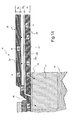
- Figures 11(a) - 11(c) show a side view of the device through a section indicated as 11-11 in Figure 10.
- the sacrificial layer 31 is enclosed within the drop emitter chamber cover 35 except for nozzle opening 30.
- the substrate 10 is intact.
- Passivation layer 21 has been removed from the surface of substrate 10 in gap area 13 and around the periphery of the cantilevered element 20. The removal of layer 21 in these locations was done at a fabrication stage before the forming of sacrificial structure 31.
- substrate 10 is removed beneath the cantilever element 20 and the liquid chamber areas around and beside the cantilever element 20.
- the removal may be done by an anisotropic etching process such as reactive ion etching, or such as orientation dependent etching for the case where the substrate used is single crystal silicon.
- anisotropic etching process such as reactive ion etching, or such as orientation dependent etching for the case where the substrate used is single crystal silicon.
- the sacrificial structure and liquid chamber steps are not needed and this step of etching away substrate 10 may be used to release the cantilevered element.
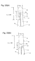
- Figures 12(a) - 12(b), illustrate a side view of a liquid drop emitter structure according to some preferred embodiments of the present invention.
- Figure 12a shows the cantilevered element 20 in a first position proximate to nozzle 30. Liquid meniscus 52 rests at the outer rim of nozzle 30.
- Figure 12b illustrates the deflection of the free end 32 of the cantilevered element 20 towards nozzle 30. The upward deflection of the cantilevered element is caused by applying an electrical pulse to the first pair of electrodes 42,44 attached to first uniform resistor portion 25 of the first deflector layer 22 (see also Figure 3b). Rapid deflection of the cantilevered element to this second position pressurizes liquid 60, overcoming the meniscus pressure at the nozzle 30 and causing a drop 50 to be emitted.
- Figures 13(a) - 13(b) illustrate a side view of a liquid drop emitter structure according to some preferred embodiments of the present invention.
- the side views of Figure 13 are formed along a line indicated as 13-13 in Figure 10.
- Figure 13a shows the cantilevered element 20 in a first position proximate to nozzle 30. Liquid meniscus 52 rests at the outer rim of nozzle 30.
- Figure 13b illustrates the deflection of the free end 32 of the cantilevered element 20 away from nozzle 30.
- the downward deflection of the cantilevered element is caused by applying an electrical pulse to the second pair of electrodes 46,48 attached to second uniform resistor portion 27 of the second deflector layer 24 (see also Figure 3b). Deflection of the cantilevered element to this downward position negatively pressurizes liquid 60 in the vicinity of nozzle 30, causing meniscus 52 to be retracted to a lower, inner rim area of nozzle 30.
- the quiescent first position may be a partially bent condition of the cantilevered element 20 rather than the horizontal condition illustrated Figures 4a,12a, 13a and 19a.
- the actuator may be bent upward or downward at room temperature because of internal stresses that remain after one or more microelectronic deposition or curing processes.
- the device may be operated at an elevated temperature for various purposes, including thermal management design and ink property control. If so, the first position may be substantially bent.
- the cantilevered element will be said to be quiescent or in its first position when the free end is not significantly changing in deflected position.
- the first position is depicted as horizontal in Figures 4a, 12a, 13a and 19a.
- operation of thermal actuators about a bent first position are known and anticipated by the inventors of the present invention and are fully within the scope of the present inventions.
- Figures 5 through 11 illustrate a preferred fabrication sequence. However, many other construction approaches may be followed using well known microelectronic fabrication processes and materials. For the purposes of the present invention, any fabrication approach which results in a cantilevered element including a first deflection layer 22, a barrier layer 23, and a second deflector layer 24 may be followed. These layers may also be composed of sub-layers or laminations in which case the thermomechanical behavior results from a summation of the properties of individual laminations. Further, in the illustrated sequence of Figures 5 through 11, the liquid chamber cover 35 and nozzle 30 of a liquid drop emitter were formed in situ on substrate 10. Alternatively a thermal actuator could be constructed separately and bonded to a liquid chamber component to form a liquid drop emitter.
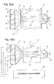
- FIG. 14 illustrates heat flows by means of arrows designating internal heat flow, Q I , and flow to the surroundings, Q S .
- Cantilevered element 20 bends, deflecting free end 32, because first deflector layer 22 is made to elongate with respect to second deflector layer 24 by the addition of a heat pulse to first deflector layer 22, or vice versa.
- thermal actuators of the cantilever configuration may be designed to have large differences in the coefficients of thermal expansion at a uniform operating temperature, to operate with a large temperature differential within the actuator, or some combination of both.
- the present inventions are designed to utilize and maximize an internal temperature differential set up between the first deflector layer 22 and second deflector layer 24.
- the first deflector layer 22 and second deflector layer 24 are constructed using materials having substantially equal coefficients of thermal expansion over the temperature range of operation of the thermal actuator. Therefore, maximum actuator deflection occurs when the maximum temperature difference between the first deflector layer 22 and second deflector layer 24 is achieved. Restoration of the actuator to a first or nominal position then will occur when the temperature equilibrates among first deflector layer 22, second deflector layer 24 and barrier layer 23. The temperature equilibration process is mediated by the characteristics of the barrier layer 23, primarily its thickness, Young's modulus, coefficient of thermal expansion and thermal conductivity.
- the temperature equilibration process may be allowed to proceed passively or heat may be added to the cooler layer. For example, if first deflector layer 22 is heated first to cause a desired deflection, then second deflector layer 24 may be heated subsequently to bring the overall cantilevered element into thermal equilibrium more quickly. Depending on the application of the thermal actuator, it may be more desirable to restore the cantilevered element to the first position even though the resulting temperature at equilibrium will be higher and it will take longer for the thermal actuator to return to an initial starting temperature.
- a cantilevered multi-layer structure comprised of j layers having different materials properties and thicknesses generally assumes a parabolic arc shape at an elevated temperature.
- Figure 15 illustrates a deflected tri-layer cantilevered element 20.
- the present inventions are based on the formation of first and second uniform resistor portions to heat first and second deflection layers, thereby setting up the temperature differences, ⁇ T, which give rise to cantilever bending.
- the uniform resistor portions do not extend for the full extended length L of the cantilevered element so as to optimize the amount of actuator deflection realized for a given input of heat energy.
- parabolic shape Equation 1 applies to the heated portion of the cantilevered element.
- An unheated tip portion 32 further extends from the heated portion as a straight-line segment as is illustrated in Figure 15.
- the second deflector layer 24 mechanically balance the first deflector layer 22 when internal thermal equilibrium is reached following a heat pulse which initially heats first deflector layer 22.
- Mechanical balance at thermal equilibrium is achieved by the design of the thickness and the materials properties of the layers of the cantilevered element, especially the coefficients of thermal expansion and Young's moduli. If any of the first deflector layer 22, barrier layer 23 or second deflector layer 24 are composed of sub-layer laminations, then the relevant properties are the effective values of the composite layer.
- the subscripts 1, b and 2 refer to the first deflector, barrier and second deflector layers, respectively.
- the parameter G is a function of the elastic parameters and dimensions of the various layers and is always a positive quantity. Exploration of the parameter G is not needed for determining when the tri-layer beam could have a net zero deflection at an elevated temperature for the purpose of understanding the present inventions.
- the quantity M in Equations 4 captures critical effects of materials properties and thickness of the layers.
- Equation 6 It may be understood from Equation 6 that if the second deflector layer 24 material is the same as the first deflector layer 22 material, then the tri-layer structure will have a net zero deflection if the thickness h 1 of first deflector layer 22 is substantially equal to the thickness h 2 of second deflector layer 24.
- Equation 2 there are many other combinations of the parameters for the second deflector layer 24 and barrier layer 23 which may be selected to provide a net zero deflection for a given first deflector layer 22.
- some variation in second deflector layer 24 thickness, Young's modulus, or both, may be used to compensate for different coefficients of thermal expansion between second deflector layer 24 and first deflector layer 22 materials.
- heat flow from a first deflector layer 22 to a second deflector layer 24 may be viewed as a heating process for the second deflector layer 24 and a cooling process for the first deflector layer 22.
- Barrier layer 23 may be viewed as establishing a time constant, ⁇ B , for heat transfer in both heating and cooling processes.
- the time constant ⁇ B is approximately proportional to the thickness h b of the barrier layer 23 and inversely proportional to the thermal conductivity of the materials used to construct this layer.
- the heat pulse input to first deflector layer 22 must be shorter in duration than the heat transfer time constant, otherwise the potential temperature differential and deflection magnitude will be dissipated by excessive heat loss through the barrier layer 23.
- the details of the external heat flows will depend importantly on the application of the thermal actuator. Heat may flow from the actuator to substrate 10, or other adjacent structural elements, by conduction. If the actuator is operating in a liquid or gas, it will lose heat via convection and conduction to these fluids. Heat will also be lost via radiation.
- heat lost to the surrounding may be characterized as a single external cooling time constant ⁇ S which integrates the many processes and pathways that are operating.
- ⁇ C Another timing parameter of importance is the desired repetition period, ⁇ C , for operating the thermal actuator.
- the actuator repetion period establishes the drop firing frequency, which establishes the pixel writing rate that a jet can sustain.
- ⁇ B the heat transfer time constant
- ⁇ B ⁇ C for energy efficiency and rapid operation.
- Uniformity in actuation performance from one pulse to the next will improve as the repetition period ⁇ C is chosen to be several units of ⁇ B or more. That is, if ⁇ C > 5 ⁇ B then the cantilevered element will have fully equilibrated and returned to the first or nominal position. If, instead ⁇ C ⁇ 2 ⁇ B , then there will be some significant amount of residual deflection remaining when a next deflection is attempted. It is therefore desirable that ⁇ C >2 ⁇ B and more preferably that ⁇ C >4 ⁇ B .
- the time constant of heat transfer to the surround, ⁇ S may influence the actuator repetition period, ⁇ C , as well.
- ⁇ S will be significantly longer than ⁇ B . Therefore, even after the cantilevered element has reached internal thermal equilibrium after a time of 3 to 5 ⁇ B , the cantilevered element will be above the ambient temperature or starting temperature, until a time of 3 to 5 ⁇ S . A new deflection may be initiated while the actuator is still above ambient temperature. However, to maintain a constant amount of mechanical actuation, higher and higher peak temperatures for the layers of the cantilevered element will be required. Repeated pulsing at periods ⁇ C ⁇ 3 ⁇ S will cause continuing rise in the maximum temperature of the actuator materials until some failure mode is reached.
- a heat sink portion 11 of substrate 10 is illustrated in Figure 14.
- the indicated heat sink portion 11 may be simply a region of the substrate 10 designated as a heat sinking location.
- a separate material may be included within substrate 10 to serve as an efficient sink for heat conducted away from the cantilevered element 20 at the anchor portion 34.
- FIG 16 illustrates the timing of heat transfers within the cantilevered element 20 and from the cantilevered 20 to the surrounding structures and materials.
- the time axis of Figure 16 is plotted in units of ⁇ C , the minimum time period for repeated actuations.
- a single heating pulse 230 having a pulse duration time of ⁇ P . Heating pulse 230 is applied to first deflector layer 22.
- Figure 16 shows four plots of temperature, T, versus time, t. Curves for the second deflector layer 24 and for the first deflector layer 22 are plotted for cantilevered element configurations having two different values of the heat transfer time constant ⁇ B . A single value for the heat transfer time constant, ⁇ S , was used for all four temperature curves. One-dimensional, exponential heating and cooling functions are assumed to generate the temperature versus time plots of Figure 16.
- curve 210 illustrates the temperature of the first deflector layer 22 and curve 212 illustrates the temperature of the second deflector layer 24 following a heat pulse applied to the first deflector layer 22.
- the amount of deflection of the cantilevered element is approximately proportional to the difference between first deflector layer temperature 210 and second deflector layer temperature 212. Hence, the cantilevered element will be restored from its deflected position to the first position at the time and temperature denoted as E in Figure 16.
- the point of internal thermal equilibrium within cantilevered element 20 is denoted F in Figure 16. Hence, the cantilevered element will be restored from its deflection position to the first position at the time and temperature denoted as F in Figure 16.
- Figure 16 also illustrates that the cantilevered element 20 will be at an elevated temperature even after reaching internal thermal equilibrium and restoration of the deflection to the first position.
- the cantilevered element 20 will be elongated at this elevated temperature but not deflected due to a balance of forces between the first deflector layer 22 and second deflector layer 24.
- the cantilevered element may be actuated from this condition of internal thermal equilibrium at an elevated temperature.
- continued application of heat pulses and actuations from such elevated temperature conditions may cause failure modes to occur as various materials in the device or working environment begin to occur as peak temperature excursions also rise. Consequently, it is advantageous to reduce the time constant of heat transfer to the surround, ⁇ S , as much as possible.
- a thermal actuator having a cantilevered design according to the present inventions will exhibit a characteristic time constant, ⁇ B , for heat transfer between first deflector layer 22 and second deflector layer 24 through barrier layer 23.
- ⁇ B characteristic time constant
- heat pulse energy is applied over a time which is short compared to the internal energy transfer process characterized by ⁇ B . Therefore it is preferable that applied heat energy or electrical pulses for electrically resistive heating have a duration of ⁇ P , where ⁇ P ⁇ B and, preferably, ⁇ P ⁇ 1 /2 ⁇ B .
- the thermal actuators of the present invention allow for active deflection on the cantilevered element 20 in substantially opposing motions and displacements.
- the cantilevered element 20 deflects in a direction away from first deflector layer 22 (see figures 4b and 12b).
- the cantilevered element 20 deflects in a direction away from the second deflector layer 24 and towards the first deflector layer 22 (see Figures 4c and 13b).
- the cantilevered element 20 also responds to passive internal mechanical forces arising from the compression or tensioning of the unheated layer materials. For example, if the first deflector layer 22 is heated causing the cantilevered element 20 to bend, the barrier layer 23 and second deflector layer 24 are mechanically compressed. The mechanical energy stored in the compressed materials leads to an opposing spring force which counters the bending, hence counters the deflection. Following a thermo-mechanical impulse caused by suddenly heating one of the deflector layers, the cantilevered element 20 will move in an oscillatory fashion until the stored mechanical energy is dissipated, in addition to the thermal relaxation processes previously discussed.
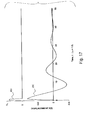
- FIG 17 illustrates the damped oscillatory behavior of a cantilevered element.
- Plot 250 shows the displacement of the free end 32 of a cantilevered element as a function of time.
- Plot 252 shows the electrical pulse which generates the initial thermo-mechanical impulse force that starts the damped oscillatory displacement.
- the time duration of the electrical pulse, ⁇ P1 is assumed to be less than one-half the internal heat transfer time constant ⁇ B , discussed previously.
- the time axis in Figure 15 is plotted in units of ⁇ P1 .
- Plot 250 of cantilevered element free end displacement illustrates a case wherein the resonant period of oscillation ⁇ R ⁇ 16 ⁇ P1 and the damping time constant ⁇ D ⁇ 8 ⁇ P1 .
- thermo-mechanical impulses via both the first and second deflector layers 22 and 24 will be a combination of both the actively applied thermo-mechanical forces as well as the internal thermal and mechanical effects.
- a desirable predetermined displacement versus time profile may be constructed utilizing the parameters of applied electrical pulses, especially the energies and time duration's, the waiting time ⁇ W1 between applied pulses, and the order in which first and second deflector layers are addressed.
- the damped resonant oscillatory motion of a cantilevered element 20, as illustrated in Figure 17, generates displacements on both sides of a quiescent or first position in response to a single thermo-mechanical impulse.
- a second, opposing, thermo-mechanical impulse may be timed, using ⁇ W1 , to amplify, or to further dampen, the oscillation begun by the first impulse.
- plots 260, 262 and 264 An activation sequence which serves to promote more rapid dampening and restoration to the first position is illustrated by plots 260, 262 and 264 in Figure 18.
- the same characteristics ⁇ B , ⁇ R, and ⁇ D of the cantilevered element 20 used to plot the damped oscillatory motion shown in Figure 17 are used in Figure 18 as well.
- Plot 260 indicates the cantilevered element deflecting rapidly in response to an electrical pulse applied to the pair of electrodes attached to the first uniform resistor portion 25 of the first deflector layer 22. This first electrical pulse is illustrated as plot 262.
- the pulse duration ⁇ P1 is the same as was used in Figure 17 and the time axis of the plots in Figure 18 are in units of ⁇ P1 .
- the initial deflection of cantilevered element 20 illustrated by plot 260 is therefore the same as for plot 250 in Figure 17.
- a second electrical pulse is applied to the pair of electrodes attached to the second uniform resistor portion 27 of the second deflector layer 22, as illustrated by plot 264 in Figure 18.
- the energy of this second electrical pulse is chosen so as to heat the second deflector layer 24 and raise its temperature to nearly that of the first deflector layer 22 at that point in time.
- the second electrical pulse 264 is shown as having the same amplitude as the first electrical pulse 262, but has a shorter time duration, ⁇ P2 ⁇ ⁇ P1 . Heating the second deflector layer in this fashion elongates the second deflector layer, releasing the compressive stored energy and balancing the forces causing the cantilevered element 20 to bend.
- the second electrical pulse applied to second deflector layer 24 has the effect of quickly damping the oscillation of the cantilevered element 20 and restoring it to the first position.
- Active restoration using a second actuation may be valuable for applications of thermal actuators wherein minimization of the duration of the initial cantilevered element deflection is important. For example, when used to activate liquid drop emitters, actively restoring the cantilevered element to a first position may be used to hasten the drop break off process, thereby producing a smaller drop than if active restoration was not used. By initiating the retreat of cantilevered element 20 at different times (by changing the waiting time ⁇ W1 ) different drop sizes may be produced.
- FIG. 19 An activation sequence that serves to alter liquid drop emission characteristics by pre-setting the conditions of the liquid and liquid meniscus in the vicinity of the nozzle 30 of a liquid drop emitter is illustrated in Figure 19.
- the conditions produced in the nozzle region of the liquid drop emitter are further illustrated in Figures 20(a) - 20(c).
- Plot 270 illustrates the deflection versus time of the cantilevered element free end 32
- plot 272 illustrates an electrical pulse sequence applied to the first pair of electrodes addressing the first deflector layer 22
- plot 274 illustrates an electrical pulse sequence applied to the second pair of electrodes attached to the second deflector layer 24.
- the same cantilevered element characteristics ⁇ B , ⁇ R, and ⁇ D are assumed for Figure 19 as for previously discussed Figures 17 and 18.
- the time axis is plotted in units of ⁇ P1 .
- the cantilevered element is first deflected an amount D 1 away from nozzle 30 by applying an electrical pulse to the second deflector layer 24 (see Figure 20a,b). This has the effect of reducing the liquid pressure at the nozzle and caused the meniscus to retreat within the nozzle 30 bore toward the liquid chamber 12. Then, after a selected waiting time ⁇ W1 , the cantilevered element is deflected an amount D 2 toward the nozzle to cause drop ejection. If the waiting time ⁇ W1 is chosen to so that the resonant motion of the cantilever element 20 caused by the initial thermo-mechanical impulse is toward the nozzle, then the second thermo-mechanical impulse will amplify this motion and a strong positive pressure impulse will cause drop formation.
- drops of differing volume and velocity may be produced.
- the formation of satellite drops may also be affected by the pre-positioning of the meniscus in the nozzle and by the timing of the positive pressure impulse.
- Plots 270, 272, and 274 in Figure 19 also show a second set of actuations to generate a second liquid drop emission after waiting a second wait time ⁇ W2 .
- This second wait time, ⁇ W2 is selected to account for the time required for the cantilevered element 20 to have restored to its first or nominal position before a next actuation pulse is applied.
- the second wait time ⁇ W2 together with the pulse times ⁇ P1 , ⁇ P2 , and inter-pulse wait time ⁇ W1 , establish the practical repetition time ⁇ C for repeating the process of liquid drop emission.
- the second wait time ⁇ W2 be much longer than the internal heat transfer time constant ⁇ B . Most preferably, it is most preferred that ⁇ W2 > 3 ⁇ B for efficient and reproducible activation of the thermal actuators and liquid drop emitters of the present invention.
- the parameters of electrical pulses applied to the dual thermo-mechanical actuation means of the present inventions, the order of actuations, and the timing of actuations with respect to the thermal actuator physical characteristics, such as the heat transfer time constant ⁇ B and the resonant oscillation period ⁇ R , provide a rich set of tools to design desirable predetermined displacement versus time profiles.
- the dual actuation capability of the thermal actuators of the present inventions allows modification of the displacement versus time profile to be managed by an electronic control system. This capability may be used to make adjustments in the actuator displacement profiles for the purpose of maintaining nominal performance in the face of varying application data, varying environmental factors, varying working liquids or loads, or the like. This capability also has significant value in creating a plurality of discrete actuation profiles that cause a plurality of predetermined effects, such as the generation of several predetermined drop volumes for creating gray level printing.
- thermomechanical structure factor design and dual actuations of the cantilevered described herein the inventors of the present inventions have discovered that the energy efficiency of a cantilevered thermal actuator can be increased by heating only a portion of the first and second deflector layers 22 and 24 to cause desired actuations.
- first deflector layer 22 may be patterned to have a portion 25 of uniform resistance which extends for only part of the cantilevered element length L.
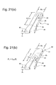
- Figures 21(a) - 21(b) further illustrates this concept.
- Figure 21 a illustrates a perspective view of patterned first deflector layer 22 as previously illustrated in Figure 5.
- the electrically resistive material of first deflector layer 22 is patterned into a u-shaped resistor by removing a first central slot 29 of material.
- first deflector layer 22 is patterned to have a first uniform resistor portion 25 which extends a shorter distance L H1 than the full cantilevered element extension L, that is, L H1 ⁇ L.
- First deflector layer 22 is illustrated as divided into three general portions by dotted lines: free end portion 32, uniform resistor portion 25, and anchored end portion 34. Electrical input electrodes 42 and 44 are formed in anchor end portion 34.
- First deflector layer 22 has thickness, h 1 .
- first deflector layer 22 When operating a cantilevered element actuator having a first deflector layer 22 design as illustrated in Figure 21b, heating will initially occur in an approximately uniform fashion over the length L H1 in uniform resistor portion 25.
- First deflector layer 22, in first uniform resistor portion 25, will elongate with respect to barrier layer 23 and second deflector layer 24 (not shown in Figure 21b) causing the cantilevered element to bend away from first deflector layer 22.
- Free end portion 32 of first deflector layer 22 will also be deflected since it is rigidly attached to uniform resistor portion 25. Free end portion 32 acts as a lever arm, further magnifying the amount of bending deflection which occurs in the directly heated first uniform resistor portion 25.
- Significant input energy may be saved because of this magnification effect.
- a desired amount of actuator deflection, D may be achieved with less input energy because only a fraction of the elongation layer is heated.
- Figures 22(a)- 22(b) are plan views of first deflector layer 22 illustrating dimensional relationships which are helpful in understanding the present inventions.
- First deflector layer 22 is shown formed into the three portions discussed previously with respect to Figure 21b: anchored end portion 34, first uniform resistor portion 25, and free end portion 32.
- Uniform heating will occur in first uniform resistor portion 25 when an electrical current is passed between input electrodes 42 and 44.
- Some significant resistive heating may occur in the anchor end portion 34.
- Such anchor end resistive heating is wasted energy and is preferably minimized by increasing the cross section area of the first deflector layer 22 material and shortening current path lengths as much as possible in the anchor end portion 34. Very little resistive heating will occur in free end portion 32 as the current path will be substantially confined to the first uniform resistor portion 25.
- the first uniform resistor portion 25 is formed by removing first deflector layer 22 material in a first central slot 29 having a length L S1 extending from the anchor location 14.
- First central slot 29 has an average width of W S1 .
- first central slot 29 is preferably formed with uniform dimensions along length L S1 .
- the width W S1 of first central slot 29 be made as narrow as is feasible consistent with defining a current path of uniform resistance.
- the barrier layer 23 material is overlaid on the previously patterned first deflector layer 22 material.
- first central slot 29 may be formed with side walls tapering from bottom to top.
- first central slot 29 is formed to an average width W S1 which is less than three times the thickness h 1 of first deflector layer 22, i. e. W S1 ⁇ 3 h 1 . Coverage of features in first deflector layer 22 having aspect ratios of height to width of 1:3 is within the capability of MEMS fabrication process methods.
- First uniform resistor portion 25 is illustrated in Figure 22 to extend to a length L H1 which is longer than first central slot 29 length L S1.
- the electrical current path through first uniform resistor portion 25 will extend outward from the end of first central slot 29 to a distance approximately equal to the width of the straight arm portions of the current path.
- the straight arm portions of the current path are approximately as wide as 1 ⁇ 2 W 1 , where W 1 is the width of the first uniform resistor portion of the first deflector layer 22 and the first central slot width W S1 is small compared to W 1 , W S1 ⁇ W 1 .
- the design of the second deflector layer 24 having a second uniform resistor portion 27 is optimized in a fashion analogous to the first deflector layer 22.
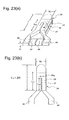
- Figures 23 (a) - 23(b) illustrate perspective and plan views of the second deflector layer 24 as previously illustrated in Figures 4, 7, and 13.
- Figure 23a illustrates a perspective view of patterned second deflector layer 24 as previously illustrated in Figure 7.
- the electrically resistive material of second deflector layer 24 is patterned into a u-shaped resistor by removing a second central slot 28 of material.
- the second uniform resistor portion 27 extends a length L H2 of full length L of the cantilevered element.
- Second deflector layer 24 has thickness, h 2 .
- Figure 23b is a plan view of second deflector layer 24 illustrating dimensional relationships which are helpful in understanding the present inventions.
- the second uniform resistor portion 27 is formed by removing second deflector layer 24 material in a second central slot 28 having a length L S2 extending from the anchor location 14.
- Second central slot 28 has an average width of W S2 .
- the second central slot 28 is preferably formed with uniform dimensions along length L S2 .
- the second deflector layer 24 material is overlaid with a passivation material to protect the cantilevered element.
- second central slot 28 may be formed with side walls tapering from bottom to top.
- second central slot 28 is formed to an average width W S2 which is less than three times the thickness h 2 of second deflector layer 24, i. e. W S2 ⁇ 3 h 2 . Coverage of features in second deflector layer 24 having aspect ratios of height to width of 1:3 is within the capability of MEMS fabrication process methods.
- Second uniform resistor portion 27 is illustrated in Figure 23 to extend to a length L H2 which is longer than second central slot 28 length L S2 .
- the electrical current path through the second uniform resistor portion 27 will extend outward from the end of second central slot 28 to a distance approximately equal to the width of the straight arm portions of the current path.
- the straight arm portions of the current path are approximately as wide as 1 ⁇ 2 W 2 , where W 2 is the width of the second uniform resistor portion of the second deflector layer 24 and the second central slot width W S2 is small compared to W 2 , W S2 ⁇ W 2 .
- ⁇ T peak temperature
- D T peak temperature
- F fractional length
- Figure 15 illustrates an idealized cantilevered element 20, the free end 32 of which has been deflected an amount D T .
- the deflection is caused by an elongation of a first uniform resistor portion 25, extending a length L H1 from an anchor location 14 of base element 10.
- the cantilevered element 20 has an extended length, L, of which the heated portion length, L H1 , is a fraction, L H1 ⁇ L.
- the first deflector layer 22 extends an amount ⁇ L H1 relative to the barrier layer 23 and second deflector layer 24.
- the unheated free end portion 32 of cantilevered element 20 extends from the end of the uniform resistor portion 25 as a straight segment tangent to the parabolic arc.
- Equation 16 shows the relationship between the peak temperature that must be reached in order to achieve an amount of deflection when the heated portion of the cantilevered element is a fraction F 1 of the overall extended length L.
- the trade-off between peak temperature and fractional heater length may be understood by examining Equation 16 for the case where the deflection D T is set equal to a constant nominal amount, D 0 , needed by the device application of the thermal actuator: ⁇ T ⁇ T 0 /F 1 (2-F 1 )
- Equation 17 is plotted as curve 280 in Figure 24.
- ⁇ T is plotted in units of ⁇ T 0 .
- ⁇ T must be approximately 20% greater than ⁇ T 0 .
- the materials of the thermal actuator and any fluids used with the actuator will have failure modes that limit the practical peak temperatures than can be used. When attempting to reduce the fractional heater length to a minimum, at some point, an unreliable level of the peak temperature will be required and further heater length reduction will be impractical.
- An important benefit of reducing the heated portion of a cantilevered element thermal actuator arises from the energy reduction that may be realized.
- ⁇ 1 is the density of the electrically resistive material used to construct first deflector layer 22.
- h 1 , W 1 , and F 1 L are the thickness, width, and length of the volume of first deflector layer 22 material that is initially heated by the electrical energy pulse.
- C 1 is the specific heat of the first deflector layer 22 electrically resistive material.
- ⁇ Q 0 C 1 ⁇ 1 h 1 W 1 L ⁇ T 0 Equation (18) may be expressed in normalized form as follows: ⁇ Q ⁇ F 1 ⁇ Q 0 ⁇ T/ ⁇ T 0 ⁇ Q ⁇ ⁇ Q 0 /(2-F 1 )
- Equation 22 describes the tradeoff between energy input and fractional heater length.
- the input pulse energy ⁇ Q normalized by the nominal input pulse energy ⁇ Q 0 is plotted as curve 282 in Figure 24.
- Curve 282 shows that the energy needed declines as the fractional heater length is decreased. Even though the material in the heated portion must be raised to a higher temperature difference, ⁇ T, less material is heated. Therefore, a net saving of input pulse energy can be realized by reducing the fractional heater length.
- Thermal actuator of fractional heater length allows less input energy to be used to accomplish the needed amount of deflection. Less energy use has many system advantages including power supply savings, driver circuitry expense, device size and packaging advantages.
- the reduced input energy also translates into improved drop repetition frequency.
- the cool down period of a thermal actuator is often the rate limiting physical effect governing drop repetition frequency. Using less energy to cause an actuation reduces the time required to dissipate the input heat energy, returning to a nominal actuator position.
- Using a fractional length uniform resistor portion 25 is additionally beneficial in that the major portion of the input heat energy resides closer to the substrate base element 10, thereby allowing quicker heat conduction from the cantilevered element 20 to the base element 10 at the end of each actuation.
- the time constant ⁇ for heat conduction from the cantilevered element may be understood to first order by a using a one-dimensional analysis of the heat conduction. Such an analysis finds that the time constant is proportional to the square of the heat flow path length.
- ⁇ 0 is the heat conduction time constant for the nominal case of a full length heater.
- Reduction in the conduction heat transfer time constant, which occurs proportionally to F 1 2 is an important system benefit when using of fractional length heater thermal actuators according to the present inventions.
- a lower temperature baseline may be maintained when repeated actuations are needed.
- multiple pulses may be supported, allowing the beginning temperature to rise between pulses, but still maintain the device temperature below some upper failure limit.
- Curves 280 and 282 in Figure 24 illustrate that there is a system trade-off involved when choosing a reduced heater length to cause the required amount of deflection. Shorter heater lengths allow reduced energy input but require higher peak temperatures which may cause reliability problems. In many systems, the percentage savings in energy and the percentage increase in temperature are approximately equal in the system impact in terms of cost and reliability. An optimization of these two quantities may be understood by forming a product of the two. A desirable energy reduction in ⁇ Q is calibrated by the undesirable increase in required temperature above the base operating temperature, ⁇ T.
- the system optimization function S of Equation 23 is plotted as curve 284 in Figure 24. It has been normalized to have units of ⁇ Q 0 ⁇ T 0 . It can be seen from curve 284 that the system optimization, S, improves to a minimum, S m , and then increases as the required ⁇ T becomes large compared to the savings in ⁇ Q.
- fractional heater lengths are selected such that F 1 > 0.3 in order to avoid device and system reliability failures caused by excessive operating temperatures.
- first deflector layer 24 and first uniform resistor portion 25 may be repeated for the second deflector layer 24 and second uniform resistor portion 27 for the preferred embodiments of the present inventions which employ dual actuation of the cantilevered element.
- the same results for an optimum selection of F 2 , the fractional length of the second uniform resistance portion, will be found as has been elucidated herein for F 1 .
- a system design which balances energy reduction with peak temperature increase is found by selecting a fractional heater length in the range: 0.3 L ⁇ L H1,2 ⁇ 0.7 L.
- This range is defined at the upper end by the fractional length which optimizes the gain in energy savings while minimizing the increase in operating temperature.
- the range is defined on the lower end by the point at which the operating temperature increase has doubled over the full length heater case and further gains in energy reduction are very small compared to the rapid increases in required operating temperatures.
- FIG. 25a A tri-layer cantilevered element which includes first and second deflector layers 22,24 and a barrier layer 23 controlling heat transfer between deflector layers.
- One or more of the three layers thus described may be formed as laminates composed of sub-layers.
- Such a construction is illustrated in Figures 25(a) - 25(b).
- the cantilevered elements of Figures 25(a) - 25(b) are constructed of a first deflector layer 22 having three sub-layers 22a, 22b, and 22c; barrier layer 23 having sub layers 23a and 23b; and second deflector layer 24 having two sub-layers 24a and 24b.
- the structure illustrated in Figure 25a has only one actuator, first uniform resistor portion 25. It is illustrated in a upward deflected position, D 1 .
- the second deflector layer 24 in Figure 25a acts as a passive restorer layer.
- both first and second deflector layers 22 and 24 are patterned with first and second uniform resistor portions 25 and 27 respectively. It is illustrated in a downward deflected position, D 2 as a result of activating the second deflector layer.
- the structure of Figure 25b may be activated either up or down by electrically pulsing the first and second uniform resister portions appropriately.
- thermal actuator devices according to the present invention may be fabricated concurrently with other electronic components and circuits, or formed on the same substrate before or after the fabrication of electronic components and circuits.
Abstract


Description
- The present invention relates generally to micro-electromechanical devices and, more particularly, to micro-electromechanical thermal actuators such as the type used in ink jet devices and other liquid drop emitters.
- Micro-electro mechanical systems (MEMS) are a relatively recent development. Such MEMS are being used as alternatives to conventional electromechanical devices as actuators, valves, and positioners. Micro-electromechanical devices are potentially low cost, due to use of microelectronic fabrication techniques. Novel applications are also being discovered due to the small size scale of MEMS devices.
- Many potential applications of MEMS technology utilize thermal actuation to provide the motion needed in such devices. For example, many actuators, valves and positioners use thermal actuators for movement. In some applications the movement required is pulsed. For example, rapid displacement from a first position to a second, followed by restoration of the actuator to the first position, might be used to generate pressure pulses in a fluid or to advance a mechanism one unit of distance or rotation per actuation pulse. Drop-on-demand liquid drop emitters use discrete pressure pulses to eject discrete amounts of liquid from a nozzle.
- Drop-on-demand (DOD) liquid emission devices have been known as ink printing devices in ink jet printing systems for many years. Early devices were based on piezoelectric actuators such as are disclosed by Kyser et al., in U.S. Patent No. 3,946,398 and Stemme in U.S. Patent No. 3,747,120. A currently popular form of ink jet printing, thermal ink jet (or "bubble jet"), uses electrically resistive heaters to generate vapor bubbles which cause drop emission, as is discussed by Hara et al., in U.S. Patent No. 4,296,421.
- Electrically resistive heater actuators have manufacturing cost advantages over piezoelectric actuators because they can be fabricated using well developed microelectronic processes. On the other hand, the thermal ink jet drop ejection mechanism requires the ink to have a vaporizable component, and locally raises ink temperatures well above the boiling point of this component. This temperature exposure places severe limits on the formulation of inks and other liquids that may be reliably emitted by thermal ink jet devices. Piezoelectrically actuated devices do not impose such severe limitations on the liquids that can be jetted because the liquid is mechanically pressurized.
- The availability, cost, and technical performance improvements that have been realized by ink jet device suppliers have also engendered interest in the devices for other applications requiring micro-metering of liquids. These new applications include dispensing specialized chemicals for micro-analytic chemistry as disclosed by Pease et al., in U.S. Patent No. 5,599,695; dispensing coating materials for electronic device manufacturing as disclosed by Naka et al., in U.S. Patent No. 5,902,648; and for dispensing microdrops for medical inhalation therapy as disclosed by Psaros et al., in U.S. Patent 5,771,882. Devices and methods capable of emitting, on demand, micron-sized drops of a broad range of liquids are needed for highest quality image printing, but also for emerging applications where liquid dispensing requires mono-dispersion of ultra small drops, accurate placement and timing, and minute increments.
- A low cost approach to micro drop emission is needed which can be used with a broad range of liquid formulations. Apparatus and methods are needed which combine the advantages of microelectronic fabrication used for thermal ink jet with the liquid composition latitude available to piezo-electromechanical devices.
- A DOD ink jet device which uses a thermo-mechanical actuator was disclosed by T. Kitahara in JP 2,030,543, filed July 21, 1988. The actuator is configured as a bi-layer cantilever moveable within an ink jet chamber. The beam is heated by a resistor causing it to bend due to a mismatch in thermal expansion of the layers. The free end of the beam moves to pressurize the ink at the nozzle causing drop emission. Recently, disclosures of a similar thermo-mechanical DOD ink jet configuration have been made by K. Silverbrook in U.S. Patent Nos. 6,067,797; 6,087,638; 6,209,989; 6,234,609; 6,239,821; 6,243,113 and 6,247,791. Methods of manufacturing thermo-mechanical ink jet devices using microelectronic processes have been disclosed by K. Silverbrook in U.S. Patent Nos. 6,180,427; 6,254,793; 6,258,284 and 6,274,056. The term "thermal actuator" and thermo-mechanical actuator will be used interchangeably herein.
- Thermo-mechanically actuated drop emitters are promising as low cost devices which can be mass produced using microelectronic materials and equipment and which allow operation with liquids that would be unreliable in a thermal ink jet device. Thermal actuators and thermal actuator style liquid drop emitters are needed which allow the movement of the actuator to be controlled to produce a predetermined displacement as a function of time. Highest repetition rates of actuation, and drop emission consistency, may be realized if the thermal actuation can be electronically controlled in concert with stored mechanical energy effects. Further, designs which maximize actuator movement as a function of input electrical energy also contribute to increased actuation repetion rates.
- For liquid drop emitters, the drop generation event relies on creating a pressure impulse in the liquid at the nozzle, but also on the state of the liquid meniscus at the time of the pressure impulse. The characteristics of drop generation, especially drop volume, velocity and satellite formation may be affected by the specific time variation of the displacement of the thermal actuator. Improved print quality may be achieved by varying the drop volume to produce varying print density levels, by more precisely controlling target drop volumes, and by suppressing satellite formation. Printing productivity may be increased by reducing the time required for the thermal actuator to return to a nominal starting displacement condition so that a next drop emission event may be initiated.
- Apparatus and methods of operation for thermal actuators and DOD emitters are needed which minimize the energy utilized and which enable improved control of the time varying displacement of the thermal actuator so as to maximize the productivity of such devices and to create liquid pressure profiles for favorable liquid drop emission characteristics.
- A useful design for thermo-mechanical actuators is a layered, or laminated, cantilevered beam anchored at one end to the device structure with a free end that deflects perpendicular to the beam. The deflection is caused by setting up thermal expansion gradients in the layered beam, perpendicular to the laminations. Such expansion gradients may be caused by temperature gradients among layers. It is advantageous for pulsed thermal actuators to be able to establish such temperature gradients quickly, and to dissipate them quickly as well, so that the actuator will rapidly restore to an initial position. An optimized cantilevered element may be constructed by using electroresistive materials which are partially patterned into heating resisters for some layers.
- A dual actuation thermal actuator configured to generate opposing thermal expansion gradients, hence opposing beam deflections, is useful in a liquid drop emitter to generate pressure impulses at the nozzle which are both positive and negative. Control over the generation and timing of both positive and negative pressure impulses allows fluid and nozzle meniscus effects to be used to favorably alter drop emission characteristics
- Cantilevered element thermal actuators, which can be operated with reduced energy and at acceptable peak temperatures, and which can be deflected in controlled displacement versus time profiles, are needed in order to build systems that can be fabricated using MEMS fabrication methods and also enable liquid drop emission at high repetition frequency with excellent drop formation characteristics.
- It is therefore an object of the present invention to provide a thermo-mechanical actuator which uses reduced input energy and which does not require excessive peak temperatures.
- It is also an object of the present invention to provide an energy efficient thermal actuator which comprises dual actuation means that move the thermal actuator in substantially opposite directions allowing rapid restoration of the actuator to a nominal position and more rapid repetitions.
- It is also an object of the present invention to provide a liquid drop emitter which is actuated by an energy efficient thermal actuator configured using a cantilevered element designed to restore to an initial position when reaching a uniform internal temperature.
- It is further an object of the present invention to provide a method of operating an energy efficient thermal actuator utilizing dual actuations to achieve a predetermined resultant time varying displacement.
- It is further an object of the present invention to provide a method of operating a liquid drop emitter having an energy efficient thermal actuator utilizing dual actuations to adjust a characteristic of the liquid drop emission.
- The foregoing and numerous other features, objects and advantages of the present invention will become readily apparent upon a review of the detailed description, claims and drawings set forth herein. These features, objects and advantages are accomplished by constructing a thermal actuator for a micro-electromechanical device comprising a base element and a cantilevered element extending a length L from the base element and normally residing at a first position before activation. The cantilevered element includes a barrier layer constructed of a dielectric material having low thermal conductivity, a first deflector layer constructed of a first electrically resistive material having a large coefficient of thermal expansion and patterned to have a first uniform resistor portion extending a length LH1 from the base element, wherein 0.3L ≤ LH1 ≤ 0.7L, and a second deflector layer constructed of a second electrically resistive material having a large coefficient of thermal expansion and patterned to have a second uniform resistor portion extending a length LH2 from the base element, wherein 0.3L ≤ LH2 ≤ 0.7L, and wherein the barrier layer is bonded between the first and second deflector layers. A first pair of electrodes is connected to the first uniform resistor portion to apply an electrical pulse to cause resistive heating of the first deflector layer, resulting in a thermal expansion of the first deflector layer relative to the second deflector layer. A second pair of electrodes connected to the second uniform resistor portion to apply an electrical pulse to cause resistive heating of the second deflector layer, resulting in a thermal expansion of the second deflector layer relative to the first deflector layer. Application of an electrical pulse to either the first pair or the second pair of electrodes causes deflection of the cantilevered element away from the first position to a second position, followed by restoration of the cantilevered element to the first position as heat diffuses through the barrier layer and the cantilevered element reaches a uniform temperature.
- The present invention is particularly useful as a thermal actuator for liquid drop emitters used as printheads for DOD ink jet printing. In this preferred embodiment the thermal actuator resides in a liquid-filled chamber that includes a nozzle for ejecting liquid. The thermal actuator includes a cantilevered element extending a length L from a wall of the chamber and a free end residing in a first position proximate to the nozzle. Application of an electrical pulse to either the first pair or the second pair of electrodes causes deflection of the cantilevered element away from its first position and, alternately, causes a positive or negative pressure in the liquid at the nozzle. Application of electrical pulses to the first and second pairs of electrodes, and the timing thereof, are used to adjust the characteristics of liquid drop emission.
- Figure 1 is a schematic illustration of an ink jet system according to the present invention;
- Figure 2 is a plan view of an array of ink jet units or liquid drop emitter units according to the present invention;
- Figures 3(a) and 3(b) are enlarged plan views of an individual ink jet unit shown in Figure 2;
- Figure s 4(a) - 4(c) are side views illustrating the movement of a thermal actuator according to the present invention;
- Figure 5 is a perspective view of the early stages of a process suitable for constructing a thermal actuator according to the present invention wherein a first deflector layer of the cantilevered element having a first uniform resistor portion is formed;
- Figure 6 is a perspective view of the next stages of the process illustrated in Figure 5 wherein a barrier layer of the cantilevered element is formed;
- Figure 7 is a perspective view of the next stages of the process illustrated in Figs. 5 and 6 wherein a second deflector layer of the cantilevered element having a second uniform resistor portion is formed;
- Figure 8 is a perspective view of the next stages of the process illustrated in Figs. 5 and 6 wherein an alternate design of the second deflector layer, not having a uniform resistor portion, is formed;
- Figure 9 is a perspective view of the next stages of the process illustrated in Figs. 5-8 wherein a sacrificial layer in the shape of the liquid filling a chamber of a drop emitter according to the present invention is formed;
- Figure 10 is a perspective view of the next stages of the process illustrated in Figs. 5-9 wherein a liquid chamber and nozzle of a drop emitter according to the present invention are formed;
- Figures 11 (a) - 11 (c) are side views of the final stages of the process illustrated in Figs. 5-10 wherein a liquid supply pathway is formed and the sacrificial layer is removed to complete a liquid drop emitter according to the present invention;
- Figures 12(a) - 12(b) are side views illustrating the application of an electrical pulse to the first pair of electrodes of a drop emitter according the present invention;
- Figures 13(a) - 13(b) are side views illustrating the application of an electrical pulse to the second pair of electrodes of a drop emitter according the present invention;
- Figure 14 is a side view illustrating heat flows within and out of a cantilevered element according to the present invention;
- Figure 15 is a side view of a cantilevered element illustrating the heated and unheated portions of the cantilever deflection.
- Figure 16 is a plot of temperature versus time for deflector and second deflector layers for two configurations of the barrier layer of a cantilevered element according to the present invention;
- Figure 17 is an illustration of damped resonant oscillatory motion of a cantilevered beam subjected to a deflection impulse;
- Figure 18 is an illustration of some alternate applications of electrical pulses to affect the displacement versus time of a thermal actuator according to the present invention.
- Figure 19 is an illustration of some alternate applications of electrical pulses to affect the characteristics of drop emission according to the present invention.
- Figures 20(a) - 20(c) are side views illustrating the application of an electrical pulse to the second pair and then to the first pair of electrodes to cause drop emission according to the present inventions;
- Figures 21 (a) - 21 (b) are perspective views of first deflector layer designs to illustrate a preferred embodiment of the present invention;
- Figures 22(a) - 22(b) are plan views of first deflector layer designs to illustrate a preferred embodiment of the present invention;
- Figures 23(a) - 23(b) are a perspective and plan view of second deflector layer designs to illustrate a preferred embodiment of the present invention;
- Figure 24 is a plot of thermal actuator performance attributes of the present inventions;
- Figures 25(a) - 25(b) are side views illustrating multi-layer laminate constructions according to the present inventions.
-
- The invention has been described in detail with particular reference to certain preferred embodiments thereof, but it will be understood that variations and modifications can be effected within the scope of the invention.
- As described in detail herein below, the present invention provides apparatus for a thermo-mechanical actuator and a drop-on-demand liquid emission device and methods of operating same. The most familiar of such devices are used as printheads in ink jet printing systems. Many other applications are emerging which make use of devices similar to ink jet printheads, however which emit liquids other than inks that need to be finely metered and deposited with high spatial precision. The terms ink jet and liquid drop emitter will be used herein interchangeably. The inventions described below provide apparatus and methods for operating drop emitters based on thermal actuators so as to improve overall drop emission productivity.
- Turning first to Figure 1, there is shown a schematic representation of an ink jet printing system which may use an apparatus and be operated according to the present invention. The system includes an image data source 400 which provides signals that are received by controller 300 as commands to print drops. Controller 300 outputs signals to a source of electrical pulses 200. Pulse source 200, in turn, generates an electrical voltage signal composed of electrical energy pulses which are applied to electrically resistive means associated with each thermal actuator 15 within ink jet printhead 100. The electrical energy pulses cause a thermal actuator 15 to rapidly bend, pressurizing ink 60 located at nozzle 30, and emitting an ink drop 50 which lands on receiver 500. The present invention causes the emission of drops having substantially the same volume and velocity, that is, having volume and velocity within +/- 20% of a nominal value. Some drop emitters may emit a main drop and very small trailing drops, termed satellite drops. The present invention assumes that such satellite drops are considered part of the main drop emitted in serving the overall application purpose, e.g., for printing an image pixel or for micro dispensing an increment of fluid.
- Figure 2 shows a plan view of a portion of ink jet printhead 100. An array of thermally actuated ink jet units 110 is shown having nozzles 30 centrally aligned, and ink chambers 12, interdigitated in two rows. The ink jet units 110 are formed on and in a substrate 10 using microelectronic fabrication methods. An example fabrication sequence which may be used to form drop emitters 110 is described in co-pending application Serial No. 09/726,945 filed Nov. 30, 2000, for "Thermal Actuator", assigned to the assignee of the present invention.
- Each drop emitter unit 110 has an associated first pair of electrodes 42, 44 which are formed with, or are electrically connected to, a u-shaped electrically resistive heater portion in a first deflector layer of the thermal actuator 15 and which participates in the thermo-mechanical effects as will be described hereinbelow. Each drop emitter unit 110 also has an associated second pair of electrodes 46, 48 which are formed with, or are electrically connected to, a u-shaped electrically resistive heater portion in a second deflector layer of the thermal actuator 15 and which also participates in the thermo-mechanical effects as will be described hereinbelow. The u-shaped resistor portions formed in the first and second deflector layers are exactly above one another and are indicated by phantom lines in Figure 2. Element 80 of the printhead 100 is a mounting structure which provides a mounting surface for microelectronic substrate 10 and other means for interconnecting the liquid supply, electrical signals, and mechanical interface features.
- Figure 3a illustrates a plan view of a single drop emitter unit 110 and a second plan view Figure 3b with the liquid chamber cover 35, including nozzle 30, removed.
- The thermal actuator 15, shown in phantom in Figure 3a can be seen with solid lines in Figure 3b. The cantilevered element 20 of thermal actuator 15 extends from edge 14 of liquid chamber 12 which is formed in substrate 10. Cantilevered element portion 34 is bonded to substrate 10 which serves as a base element anchoring the cantilever.
- The cantilevered element 20 of the actuator has the shape of a paddle, an extended flat shaft ending with a disc of larger diameter than the shaft width. This shape is merely illustrative of cantilever actuators which can be used, many other shapes are applicable. The paddle shape aligns the nozzle 30 with the center of the actuator free end 32. The fluid chamber 12 has a curved wall portion at 16 which conforms to the curvature of the actuator free end 32, spaced away to provide clearance for the actuator movement.
- Figure 3b illustrates schematically the attachment of electrical pulse source 200 to electrically resistive heater portion 27 of the second deflector layer at a second pair of electrodes 46 and 48. Voltage differences are applied to electrodes 46 and 48 to cause resistance heating of the second deflector layer via u-shaped resistor 27. This is generally indicated by an arrow showing a current I. The u-shaped resistor portion 25 of the first deflector layer is hidden below resistive heater portion 27 (and a barrier layer) but can be seen indicated by phantom lines emerging to make contact to a first pair of electrodes 42 and 44. Voltage differences are applied to electrodes 42 and 44 to cause resistance heating of the first deflector layer via u-shaped resistor 25. Resistor portions 25 and 27 are designed to provide a substantially uniform resistance pathway to the electrical current thus uniformly applying heat to the layer in which they are patterned. While illustrated as four separate electrodes 42,44,46, and 48, having connections to electrical pulse source 200, one member of each pair of electrodes could be brought into electrical contact at a common point so that resistive heater portions 25 and 27 could be addressed using three inputs from electrical pulse source 200.
- In the plan views of Figures 3(a) and 3(b), the actuator free end 32 moves toward the viewer when the first deflector layer is heated appropriately by first uniform resistor portion 25 and drops are emitted toward the viewer from the nozzle 30 in liquid chamber cover 35. This geometry of actuation and drop emission is called a "roof shooter" in many ink jet disclosures. The actuator free end 32 moves away from the viewer of Figure 3, and nozzle 30, when the second deflector layer is heated by second uniform resistor portion 27. This actuation of free end 32 away from nozzle 30 may be used to restore the cantilevered element 20 to a nominal position, to alter the state of the liquid meniscus at nozzle 30, to change the liquid pressure in the fluid chamber 12 or some combination of these and other effects.
- Figures 4(a)- 4(c) illustrate in side view a cantilevered thermal actuator 15 according to a preferred embodiment of the present invention. In Figure 4a thermal actuator 15 is in a first position and in Figure 4b it is shown deflected upward to a second position. The side views of Figures 4a and 4b are formed along line 4a-4a in plan view Figure 3b. In side view Figure 4c, formed along line 4b-4b of plan view Figure 3b, thermal actuator 15 is illustrated as deflected downward to a third position. Cantilevered element 20 is anchored to substrate 10 which serves as a base element for the thermal actuator. Cantilevered element 20 extends a distance L from wall edge 14 of substrate base element 10.
- Cantilevered element 20 is constructed of several layers or laminations. Layer 22 is the first deflector layer which causes the upward deflection when it is thermally elongated with respect to other layers in cantilevered element 20. Layer 24 is the second deflector layer which causes the downward deflection of thermal actuator 15 when it is thermally elongated with respect of the other layers in cantilevered element 20. First and second deflector layers are preferably constructed of materials that respond to temperature with substantially the same thermo-mechanical effects.
- The second deflector layer mechanically balances the first deflector layer, and vice versa, when both are in thermal equilibrium. This balance many be readily achieved by using the same material for both the first deflector layer 22 and the second deflector layer 24. The balance may also be achieved by selecting materials having substantially equal coefficients of thermal expansion and other properties to be discussed hereinbelow.
- For some of the embodiments of the present invention the second deflector layer 24 is not patterned with a second uniform resister portion 27. For these embodiments, second deflector layer 24 acts as a passive restorer layer which mechanically balances the first deflector layer when the cantilevered element 20 reaches a uniform internal temperature.
- The cantilevered element 20 also includes a barrier layer 23, interposed between the first deflector layer 22 and second deflector layer 24. The barrier layer 23 is constructed of a material having a low thermal conductivity with respect to the thermal conductivity of the material used to construct the first deflector layer 24. The thickness and thermal conductivity of barrier layer 23 is chosen to provide a desired time constant τB for heat transfer from first deflector layer 24 to second deflector layer 22. Barrier layer 23 may also be a dielectric insulator to provide electrical insulation, and partial physical definition, for the electrically resistive heater portions of the first and second deflector layers.
- Barrier layer 23 may be composed of sub-layers, laminations of more than one material, so as to allow optimization of functions of heat flow management, electrical isolation, and strong bonding of the layers of the cantilevered element 20. Multiple sub-layer construction of barrier layer 23 may also assist the discrimination of patterning fabrication processes utilized to form the uniform resistor portions of the first and second deflector layers.
- First and second deflector layers 22 and 24 likewise may be composed of sub-layers, laminations of more than one material, so as to allow optimization of functions of electrical parameters, thickness, balance of thermal expansion effects, electrical isolation, strong bonding of the layers of the cantilevered element 20, and the like. Multiple sub-layer construction of first and second deflector layers 22 and 24 may also assist the discrimination of patterning fabrication processes utilized to form the uniform resistor portions of the first and second deflector layers.
- Passivation layer 21 shown in Figure 4 is provided to protect the cantilevered element 20 chemically and electrically. Such protection may not be needed for some applications of thermal actuators according to the present invention, in which case it may be deleted. Liquid drop emitters utilizing thermal actuators which are touched on one or more surfaces by the working liquid may require passivation layer 21 which is chemically and electrically inert to the working liquid.
- In Figure 4b, a heat pulse has been applied to first deflector layer 22, causing it to rise in temperature and elongate. Second deflector layer 24 does not elongate initially because barrier layer 23 prevents immediate heat transfer to it. The difference in temperature, hence, elongation, between first deflector layer 22 and the second deflector layer 24 causes the cantilevered element 20 to bend upward. When used as actuators in drop emitters the bending response of the cantilevered element 20 must be rapid enough to sufficiently pressurize the liquid at the nozzle. Typically, electrical first uniform resistor portion 25 of the first deflector layer is adapted to apply appropriate heat pulses when an electrical pulse duration of less than 10 µsecs., and, preferably, a duration less than 4 µsecs., is used.
- In Figure 4c, a heat pulse has been applied to second deflector layer 24, causing it to rise in temperature and elongate. First deflector layer 22 does not elongate initially because barrier layer 23 prevents immediate heat transfer to it. The difference in temperature, hence, elongation, between second deflector layer 24 and the first deflector layer 22 causes the cantilevered element 20 to bend downward. Typically, second uniform resistor portion 27 of the second deflector layer is adapted to apply appropriate heat pulses when an electrical pulse duration of less than 10 µsecs., and, preferably, a duration less than 4 µsecs., is used.
- Depending on the application of the thermal actuator, the energy of the electrical pulses, and the corresponding amount of cantilever bending that results, may be chosen to be greater for one direction of deflection relative to the other. In many applications, deflection in one direction will be the primary physical actuation event. Deflections in the opposite direction will then be used to make smaller adjustments to the cantilever displacement for pre-setting a condition or for restoring the cantilevered element to its quiescent first position.
- Figures 5 through 11 illustrate fabrication processing steps for constructing a single liquid drop emitter according to some of the preferred embodiments of the present invention. For these embodiments the first deflector layer 22 is constructed using an electrically resistive material, such as titanium aluminide, and a portion 25 is patterned into a resistor for carrying electrical current, I. A second deflector layer 24 is constructed also using an electrically resistive material, such as titanium aluminide, and a portion 27 is patterned into a resistor for carrying electrical current, I.
- Figure 5 illustrates a first deflector layer 22 portion of a cantilever in a first stage of fabrication. The illustrated structure is formed on a substrate 10, for example, single crystal silicon, by standard microelectronic deposition and patterning methods. Deposition of intermetallic titanium aluminide may be carried out, for example, by RF or pulsed DC magnetron sputtering. A first uniform resistor portion 25 is patterned in first deflector layer 22. The current path is indicated by an arrow and letter "I". First uniform resistor portion 25 does not extend the full length, L of the cantilevered element as is illustrated in Figure 4b. A first pair of electrodes 42 and 44 for addressing the first uniform resistor portion 25 are illustrated as being formed in the first deflector layer 22 material. Electrodes 42, 44 may make contact with circuitry previously formed in substrate 10 or may be contacted externally by other standard electrical interconnection methods, such as tape automated bonding (TAB) or wire bonding. A passivation layer 21 is formed on substrate 10 before the deposition and patterning of the deflection layer material. This passivation layer may be left under deflection layer 22 and other subsequent structures or patterned away in a subsequent patterning process.
- Figure 6 illustrates a barrier layer 23 having been deposited and patterned over the previously formed first deflector layer 22 portion of the thermal actuator. The barrier layer 23 material has low thermal conductivity compared to the first deflector layer 22. For example, barrier layer 23 may be silicon dioxide, silicon nitride, aluminum oxide or some multi-layered lamination of these materials or the like.
- Favorable efficiency of the thermal actuator is realized if the barrier layer 23 material has thermal conductivity substantially below that of both the first deflector layer 22 material and the second deflector layer 24 material. For example, dielectric oxides, such as silicon oxide, will have thermal conductivity several orders of magnitude smaller than intermetallic materials such as titanium aluminide. Low thermal conductivity allows the barrier layer 23 to be made thin relative to the first deflector layer 22 and second deflector layer 24. Heat stored by barrier layer 23 is not useful for the thermo-mechanical actuation process. Minimizing the volume of the barrier layer improves the energy efficiency of the thermal actuator and assists in achieving rapid restoration from a deflected position to a starting first position. The thermal conductivity of the barrier layer 23 material is preferably less than one-half the thermal conductivity of the first deflector layer or second deflector layer materials, and more preferably, less than one-tenth.
- Figure 7 illustrates a second deflector layer 24 having been deposited and patterned over the previously formed barrier layer 23. A second uniform resistor portion 27 is patterned in second deflector layer 24. The current path is indicated by an arrow and letter "I". Second uniform resistor portion 27 does not extend the full length, L of the cantilevered element as is illustrated in Figure 4c. In the illustrated embodiment, a second pair of electrodes 46 and 48, for addressing second uniform resistor portion 27, are formed in the second deflector layer 24 material brought over the barrier layer 23 to contact positions on either side of the first pair of electrodes 42 and 44. Electrodes 46 and 48 may make contact with circuitry previously formed in substrate 10 or may be contacted externally by other standard electrical interconnection methods, such as tape automated bonding (TAB) or wire bonding.
- In some preferred embodiments of the present inventions, the second deflector layer 24 is not patterned to have a uniform resistor portion. For these embodiments, second deflector layer 24 acts as a passive restorer layer which mechanically balances the first deflector layer when the cantilevered element 20 reaches a uniform internal temperature. Figure 8 illustrates this alternative configuration of second deflector layer 24. Instead of electrical input pads, thermal pathway leads 49 are formed into second deflector layer 24 to make contact with a heat sink portion of substrate 10. The thermal pathway leads 49 help to remove heat from the cantilevered element 20 after an actuation.
- In some preferred embodiments of the present invention, the same material, for example, intermetallic titanium aluminide, is used for both second deflector layer 24 and first deflector layer 22. In this case an intermediate masking step may be needed to allow patterning of the second deflector layer 24 shape without disturbing the previously delineated first deflector layer 22 shape. Alternately, barrier layer 23 may be fabricated using a lamination of two different materials, one of which is left in place protecting electrodes 42, 44 while patterning the second deflector layer 24, and then removed to result in the cantilever element intermediate structure illustrated in Figures 7 or 8.
- Additional passivation materials may be applied at this stage over the second deflector layer for chemical and electrical protection. Also, the initial passivation layer 21 is patterned away from areas through which fluid will pass from openings to be etched in substrate 10.
- Figure 9 shows the addition of a sacrificial layer 31 which is formed into the shape of the interior of a chamber of a liquid drop emitter. A suitable material for this purpose is polyimide. Polyimide is applied to the device substrate in sufficient depth to also planarize the surface which has the topography of the first deflector 22, barrier 23 and second deflector layers 24 as illustrated in Figures 7 or 8. Any material which can be selectively removed with respect to the adjacent materials may be used to construct sacrificial structure 31.
- Figure 10 illustrates drop emitter liquid chamber walls and cover formed by depositing a conformal material, such as plasma deposited silicon oxide, nitride, or the like, over the sacrificial layer structure 31. This layer is patterned to form drop emitter chamber cover 35. Nozzle 30 is formed in the drop emitter chamber, communicating to the sacrificial material layer 31, which remains within the drop emitter chamber cover 35 at this stage of the fabrication sequence.
- Figures 11(a) - 11(c) show a side view of the device through a section indicated as 11-11 in Figure 10. In Figure 11a the sacrificial layer 31 is enclosed within the drop emitter chamber cover 35 except for nozzle opening 30. Also illustrated in Figure 11a, the substrate 10 is intact. Passivation layer 21 has been removed from the surface of substrate 10 in gap area 13 and around the periphery of the cantilevered element 20. The removal of layer 21 in these locations was done at a fabrication stage before the forming of sacrificial structure 31.
- In Figure 11b, substrate 10 is removed beneath the cantilever element 20 and the liquid chamber areas around and beside the cantilever element 20. The removal may be done by an anisotropic etching process such as reactive ion etching, or such as orientation dependent etching for the case where the substrate used is single crystal silicon. For constructing a thermal actuator alone, the sacrificial structure and liquid chamber steps are not needed and this step of etching away substrate 10 may be used to release the cantilevered element.
- In Figure 11c the sacrificial material layer 31 has been removed by dry etching using oxygen and fluorine sources. The etchant gasses enter via the nozzle 30 and from the newly opened fluid supply chamber area 12, etched previously from the backside of substrate 10. This step releases the cantilevered element 20 and completes the fabrication of a liquid drop emitter structure.
- Figures 12(a) - 12(b), illustrate a side view of a liquid drop emitter structure according to some preferred embodiments of the present invention. Figure 12a shows the cantilevered element 20 in a first position proximate to nozzle 30. Liquid meniscus 52 rests at the outer rim of nozzle 30. Figure 12b illustrates the deflection of the free end 32 of the cantilevered element 20 towards nozzle 30. The upward deflection of the cantilevered element is caused by applying an electrical pulse to the first pair of electrodes 42,44 attached to first uniform resistor portion 25 of the first deflector layer 22 (see also Figure 3b). Rapid deflection of the cantilevered element to this second position pressurizes liquid 60, overcoming the meniscus pressure at the nozzle 30 and causing a drop 50 to be emitted.
- Figures 13(a) - 13(b) illustrate a side view of a liquid drop emitter structure according to some preferred embodiments of the present invention. The side views of Figure 13 are formed along a line indicated as 13-13 in Figure 10. Figure 13a shows the cantilevered element 20 in a first position proximate to nozzle 30. Liquid meniscus 52 rests at the outer rim of nozzle 30. Figure 13b illustrates the deflection of the free end 32 of the cantilevered element 20 away from nozzle 30. The downward deflection of the cantilevered element is caused by applying an electrical pulse to the second pair of electrodes 46,48 attached to second uniform resistor portion 27 of the second deflector layer 24 (see also Figure 3b). Deflection of the cantilevered element to this downward position negatively pressurizes liquid 60 in the vicinity of nozzle 30, causing meniscus 52 to be retracted to a lower, inner rim area of nozzle 30.
- In an operating emitter of the cantilevered element type illustrated, the quiescent first position may be a partially bent condition of the cantilevered element 20 rather than the horizontal condition illustrated Figures 4a,12a, 13a and 19a. The actuator may be bent upward or downward at room temperature because of internal stresses that remain after one or more microelectronic deposition or curing processes. The device may be operated at an elevated temperature for various purposes, including thermal management design and ink property control. If so, the first position may be substantially bent.
- For the purposes of the description of the present invention herein, the cantilevered element will be said to be quiescent or in its first position when the free end is not significantly changing in deflected position. For ease of understanding, the first position is depicted as horizontal in Figures 4a, 12a, 13a and 19a. However, operation of thermal actuators about a bent first position are known and anticipated by the inventors of the present invention and are fully within the scope of the present inventions.
- Figures 5 through 11 illustrate a preferred fabrication sequence. However, many other construction approaches may be followed using well known microelectronic fabrication processes and materials. For the purposes of the present invention, any fabrication approach which results in a cantilevered element including a first deflection layer 22, a barrier layer 23, and a second deflector layer 24 may be followed. These layers may also be composed of sub-layers or laminations in which case the thermomechanical behavior results from a summation of the properties of individual laminations. Further, in the illustrated sequence of Figures 5 through 11, the liquid chamber cover 35 and nozzle 30 of a liquid drop emitter were formed in situ on substrate 10. Alternatively a thermal actuator could be constructed separately and bonded to a liquid chamber component to form a liquid drop emitter.
- The flow of heat within cantilevered element 20 is a primary physical process underlying the present inventions. Figure 14 illustrates heat flows by means of arrows designating internal heat flow, QI, and flow to the surroundings, QS. Cantilevered element 20 bends, deflecting free end 32, because first deflector layer 22 is made to elongate with respect to second deflector layer 24 by the addition of a heat pulse to first deflector layer 22, or vice versa. In general, thermal actuators of the cantilever configuration may be designed to have large differences in the coefficients of thermal expansion at a uniform operating temperature, to operate with a large temperature differential within the actuator, or some combination of both. The present inventions are designed to utilize and maximize an internal temperature differential set up between the first deflector layer 22 and second deflector layer 24.
- In the preferred embodiments, the first deflector layer 22 and second deflector layer 24 are constructed using materials having substantially equal coefficients of thermal expansion over the temperature range of operation of the thermal actuator. Therefore, maximum actuator deflection occurs when the maximum temperature difference between the first deflector layer 22 and second deflector layer 24 is achieved. Restoration of the actuator to a first or nominal position then will occur when the temperature equilibrates among first deflector layer 22, second deflector layer 24 and barrier layer 23. The temperature equilibration process is mediated by the characteristics of the barrier layer 23, primarily its thickness, Young's modulus, coefficient of thermal expansion and thermal conductivity.
- The temperature equilibration process may be allowed to proceed passively or heat may be added to the cooler layer. For example, if first deflector layer 22 is heated first to cause a desired deflection, then second deflector layer 24 may be heated subsequently to bring the overall cantilevered element into thermal equilibrium more quickly. Depending on the application of the thermal actuator, it may be more desirable to restore the cantilevered element to the first position even though the resulting temperature at equilibrium will be higher and it will take longer for the thermal actuator to return to an initial starting temperature.
- A cantilevered multi-layer structure comprised of j layers having different materials properties and thicknesses, generally assumes a parabolic arc shape at an elevated temperature. Figure 15 illustrates a deflected tri-layer cantilevered element 20. The deflection DC(x,T) of the mechanical centerline of the cantilever, as a function of temperature above a base temperature, ΔT, and the distance x from the anchor edge 14, is proportional to the materials properties and thickness according to the following relationship:where

 E j , h j , σj and αj are the Young's modulus, thickness, Poisson's ratio and coefficient to thermal expansion, respectively, of the jth layer.
- The present inventions are based on the formation of first and second uniform resistor portions to heat first and second deflection layers, thereby setting up the temperature differences, ΔT, which give rise to cantilever bending. As will be further explained hereinbelow, the uniform resistor portions do not extend for the full extended length L of the cantilevered element so as to optimize the amount of actuator deflection realized for a given input of heat energy. Hence parabolic shape Equation 1 applies to the heated portion of the cantilevered element. An unheated tip portion 32 further extends from the heated portion as a straight-line segment as is illustrated in Figure 15. Before further describing the energy optimization considerations, it is useful to understand the properties of the layers, j, of cantilevered element 20, which are appropriate for practicing the present inventions.
- As has been previously stated, for the purposes of the present inventions, it is desirable that the second deflector layer 24 mechanically balance the first deflector layer 22 when internal thermal equilibrium is reached following a heat pulse which initially heats first deflector layer 22. Mechanical balance at thermal equilibrium is achieved by the design of the thickness and the materials properties of the layers of the cantilevered element, especially the coefficients of thermal expansion and Young's moduli. If any of the first deflector layer 22, barrier layer 23 or second deflector layer 24 are composed of sub-layer laminations, then the relevant properties are the effective values of the composite layer.
- The present inventions may be understood by considering the conditions necessary for a zero net deflection, D(x,ΔT) = 0, for any elevated, but uniform, temperature of the cantilevered element, ΔT ≠ 0. From Equation 1 it is seen that this condition requires that the thermomechanical structure factor c = 0. Any non-trivial combination of layer material properties and thicknesses which results in the thermomechanical structure factor c = 0, Equations 2-3, will enable practice of the present inventions. That is, a cantilever design having c = 0 can be activated by setting up temporal temperature gradients among layers, causing a temporal deflection of the cantilever. Then, as the layers of the cantilever approach a uniform temperature via thermal conduction, the cantilever will be restored to an undeflected position, because the equilibrium thermal expansion effects have been balanced by design.
- For the case of a tri-layer cantilever, j = 3, and with the simplifying assumption that the Poisson's ratio is the same for all three material layers, the thermomechanical structure factor c can be shown to be proportional the following quantity:where

- The quantity M in Equations 4 captures critical effects of materials properties and thickness of the layers. The tri-layer cantilever will have a net zero deflection, D(x,ΔT) = 0, for an elevated value of ΔT, if M = 0. Examining Equation 4. the condition M = 0 occurs when:For the special case when layer thickness, h1 = h2, coefficients of thermal expansion, α1 = α2 , and Young's moduli, E1 = E2 , the quantity M is zero and there is zero net deflection, even at an elevated temperature, i.e. ΔT ≠ 0.

- It may be understood from Equation 6 that if the second deflector layer 24 material is the same as the first deflector layer 22 material, then the tri-layer structure will have a net zero deflection if the thickness h1 of first deflector layer 22 is substantially equal to the thickness h2 of second deflector layer 24.
- It may also be understood from Equation 2 there are many other combinations of the parameters for the second deflector layer 24 and barrier layer 23 which may be selected to provide a net zero deflection for a given first deflector layer 22. For example, some variation in second deflector layer 24 thickness, Young's modulus, or both, may be used to compensate for different coefficients of thermal expansion between second deflector layer 24 and first deflector layer 22 materials.
- All of the combinations of the layer parameters captured in Equations 2- 6 that lead to a net zero deflection for a tri-layer or more complex multi-layer cantilevered structure, at an elevated temperature ΔT, are anticipated by the inventors of the present inventions as viable embodiments of the present inventions.
- Returning to Figure 14, the internal heat flows QI are driven by the temperature differential among layers. For the purpose of understanding the present inventions, heat flow from a first deflector layer 22 to a second deflector layer 24 may be viewed as a heating process for the second deflector layer 24 and a cooling process for the first deflector layer 22. Barrier layer 23 may be viewed as establishing a time constant, τB, for heat transfer in both heating and cooling processes.
- The time constant τB is approximately proportional to the thickness hb of the barrier layer 23 and inversely proportional to the thermal conductivity of the materials used to construct this layer. As noted previously, the heat pulse input to first deflector layer 22 must be shorter in duration than the heat transfer time constant, otherwise the potential temperature differential and deflection magnitude will be dissipated by excessive heat loss through the barrier layer 23.
- A second heat flow ensemble, from the cantilevered element to the surroundings, is indicated by arrows marked QS. The details of the external heat flows will depend importantly on the application of the thermal actuator. Heat may flow from the actuator to substrate 10, or other adjacent structural elements, by conduction. If the actuator is operating in a liquid or gas, it will lose heat via convection and conduction to these fluids. Heat will also be lost via radiation. For purpose of understanding the present inventions, heat lost to the surrounding may be characterized as a single external cooling time constant τS which integrates the many processes and pathways that are operating.
- Another timing parameter of importance is the desired repetition period, τC, for operating the thermal actuator. For example, for a liquid drop emitter used in an ink jet printhead, the actuator repetion period establishes the drop firing frequency, which establishes the pixel writing rate that a jet can sustain. Since the heat transfer time constant τB governs the time required for the cantilevered element to restore to a first position, it is preferred that τB<<τC for energy efficiency and rapid operation. Uniformity in actuation performance from one pulse to the next will improve as the repetition period τC is chosen to be several units of τB or more. That is, if τC> 5τB then the cantilevered element will have fully equilibrated and returned to the first or nominal position. If, instead τC<2τB, then there will be some significant amount of residual deflection remaining when a next deflection is attempted. It is therefore desirable that τC>2τB and more preferably that τC>4τB.
- The time constant of heat transfer to the surround, τS, may influence the actuator repetition period, τC, as well. For an efficient design, τS will be significantly longer than τB. Therefore, even after the cantilevered element has reached internal thermal equilibrium after a time of 3 to 5 τB, the cantilevered element will be above the ambient temperature or starting temperature, until a time of 3 to 5 τS. A new deflection may be initiated while the actuator is still above ambient temperature. However, to maintain a constant amount of mechanical actuation, higher and higher peak temperatures for the layers of the cantilevered element will be required. Repeated pulsing at periods τC<3τS will cause continuing rise in the maximum temperature of the actuator materials until some failure mode is reached.
- A heat sink portion 11 of substrate 10 is illustrated in Figure 14. When a semiconductor or metallic material such as silicon is used for substrate 10, the indicated heat sink portion 11 may be simply a region of the substrate 10 designated as a heat sinking location. Alternatively, a separate material may be included within substrate 10 to serve as an efficient sink for heat conducted away from the cantilevered element 20 at the anchor portion 34.
- Figure 16 illustrates the timing of heat transfers within the cantilevered element 20 and from the cantilevered 20 to the surrounding structures and materials. Temperature, T, is plotted on a scale normalized over the intended range of temperature excursion of the first deflector layer 22 above its steady state operating temperature. That is, T=1 in Figure 16 is the maximum temperature reached by the first deflector layer after a heat pulse has been applied and T=0 in Figure 16 is the base or steady state temperature of the cantilevered element. The time axis of Figure 16 is plotted in units of τC, the minimum time period for repeated actuations. Also illustrated in Figure 16 is a single heating pulse 230 having a pulse duration time of τP. Heating pulse 230 is applied to first deflector layer 22.
- Figure 16 shows four plots of temperature, T, versus time, t. Curves for the second deflector layer 24 and for the first deflector layer 22 are plotted for cantilevered element configurations having two different values of the heat transfer time constant τB. A single value for the heat transfer time constant, τS, was used for all four temperature curves. One-dimensional, exponential heating and cooling functions are assumed to generate the temperature versus time plots of Figure 16.
- In Figure 16, curve 210 illustrates the temperature of the first deflector layer 22 and curve 212 illustrates the temperature of the second deflector layer 24 following a heat pulse applied to the first deflector layer 22. For curves 210 and 212, the barrier layer 23 heat transfer time constant is τB=0.3τC and the time constant for cooling to the surround, τS=2.0τC. Figure 16 shows the second deflector layer 24 temperature 212 rising as the first deflector layer 22 temperature 210 falls, until internal equilibrium is reached at the point denoted E. After point E, the temperature of both layers 22 and 24 continues to decline together at a rate governed by τS=2.0τC. The amount of deflection of the cantilevered element is approximately proportional to the difference between first deflector layer temperature 210 and second deflector layer temperature 212. Hence, the cantilevered element will be restored from its deflected position to the first position at the time and temperature denoted as E in Figure 16.
- The second pair of temperature curves, 214 and 216, illustrate the first deflector layer temperature and second deflector layer temperature, respectively, for the case of a shorter barrier layer time constant, τB=0.1 τC. The surround cooling time constant for curves 214 and 216 is also τS=2.0 τC as for curves 210 and 212. The point of internal thermal equilibrium within cantilevered element 20 is denoted F in Figure 16. Hence, the cantilevered element will be restored from its deflection position to the first position at the time and temperature denoted as F in Figure 16.
- It may be understood from the illustrative temperature plots of Figure 16 that it is advantageous that τB is small with respect to τC in order that the cantilevered element is restored to its first or nominal position before a next actuation is initiated. If a next actuation were initiated at time t =1.0 τC, it can be understood from equilibrium points E and F that the cantilevered element would be fully restored to its first position when τB=0.1 τC. If τB=0.3 τC, however, it would be starting from a somewhat deflected position, indicated by the small temperature difference between curves 210 and 212 at time t = 1.0 τC.
- Figure 16 also illustrates that the cantilevered element 20 will be at an elevated temperature even after reaching internal thermal equilibrium and restoration of the deflection to the first position. The cantilevered element 20 will be elongated at this elevated temperature but not deflected due to a balance of forces between the first deflector layer 22 and second deflector layer 24. The cantilevered element may be actuated from this condition of internal thermal equilibrium at an elevated temperature. However, continued application of heat pulses and actuations from such elevated temperature conditions may cause failure modes to occur as various materials in the device or working environment begin to occur as peak temperature excursions also rise. Consequently, it is advantageous to reduce the time constant of heat transfer to the surround, τS, as much as possible.
- In operating the thermal actuators according to the present inventions, it is advantageous to select the electrical pulsing parameters with recognition of the heat transfer time constant, τB, of the barrier layer 23. Once designed and fabricated, a thermal actuator having a cantilevered design according to the present inventions, will exhibit a characteristic time constant, τB, for heat transfer between first deflector layer 22 and second deflector layer 24 through barrier layer 23. For efficient energy use and maximum deflection performance, heat pulse energy is applied over a time which is short compared to the internal energy transfer process characterized by τB. Therefore it is preferable that applied heat energy or electrical pulses for electrically resistive heating have a duration of τP, where τP<τB and, preferably, τP< 1 /2τB.
- The thermal actuators of the present invention allow for active deflection on the cantilevered element 20 in substantially opposing motions and displacements. By applying an electrical pulse to heat the first deflector layer 22, the cantilevered element 20 deflects in a direction away from first deflector layer 22 (see figures 4b and 12b). By applying an electrical pulse to heat the second deflector layer 24, the cantilevered element 20 deflects in a direction away from the second deflector layer 24 and towards the first deflector layer 22 (see Figures 4c and 13b). The thermo-mechanical forces that cause the cantilevered element 20 to deflect become balanced if internal thermal equilibrium is then allowed to occur via internal heat transfer, for cantilevered elements 20 designed to satisfy above Equation 6, that is, when the thermomechanical structure factor c = 0.
- In addition to the passive internal heat transfer and external cooling processes, the cantilevered element 20 also responds to passive internal mechanical forces arising from the compression or tensioning of the unheated layer materials. For example, if the first deflector layer 22 is heated causing the cantilevered element 20 to bend, the barrier layer 23 and second deflector layer 24 are mechanically compressed. The mechanical energy stored in the compressed materials leads to an opposing spring force which counters the bending, hence counters the deflection. Following a thermo-mechanical impulse caused by suddenly heating one of the deflector layers, the cantilevered element 20 will move in an oscillatory fashion until the stored mechanical energy is dissipated, in addition to the thermal relaxation processes previously discussed.
- Figure 17 illustrates the damped oscillatory behavior of a cantilevered element. Plot 250 shows the displacement of the free end 32 of a cantilevered element as a function of time. Plot 252 shows the electrical pulse which generates the initial thermo-mechanical impulse force that starts the damped oscillatory displacement. The time duration of the electrical pulse, τP1, is assumed to be less than one-half the internal heat transfer time constant τB, discussed previously. The time axis in Figure 15 is plotted in units of τP1. Plot 250 of cantilevered element free end displacement illustrates a case wherein the resonant period of oscillation τR ∼16 τP1 and the damping time constant τD ∼ 8 τP1. It may be understood from Figure 17 that the resultant motion of a cantilevered element 20, which is subjected to thermo-mechanical impulses via both the first and second deflector layers 22 and 24 will be a combination of both the actively applied thermo-mechanical forces as well as the internal thermal and mechanical effects.
- A desirable predetermined displacement versus time profile may be constructed utilizing the parameters of applied electrical pulses, especially the energies and time duration's, the waiting time τW1 between applied pulses, and the order in which first and second deflector layers are addressed. The damped resonant oscillatory motion of a cantilevered element 20, as illustrated in Figure 17, generates displacements on both sides of a quiescent or first position in response to a single thermo-mechanical impulse. A second, opposing, thermo-mechanical impulse may be timed, using τW1, to amplify, or to further dampen, the oscillation begun by the first impulse.
- An activation sequence which serves to promote more rapid dampening and restoration to the first position is illustrated by plots 260, 262 and 264 in Figure 18. The same characteristics τB, τR, and τD of the cantilevered element 20 used to plot the damped oscillatory motion shown in Figure 17 are used in Figure 18 as well. Plot 260 indicates the cantilevered element deflecting rapidly in response to an electrical pulse applied to the pair of electrodes attached to the first uniform resistor portion 25 of the first deflector layer 22. This first electrical pulse is illustrated as plot 262. The pulse duration τP1 is the same as was used in Figure 17 and the time axis of the plots in Figure 18 are in units of τP1. The initial deflection of cantilevered element 20 illustrated by plot 260 is therefore the same as for plot 250 in Figure 17.
- After a short waiting time, τW1, a second electrical pulse is applied to the pair of electrodes attached to the second uniform resistor portion 27 of the second deflector layer 22, as illustrated by plot 264 in Figure 18. The energy of this second electrical pulse is chosen so as to heat the second deflector layer 24 and raise its temperature to nearly that of the first deflector layer 22 at that point in time. In the illustration of Figure 18, the second electrical pulse 264 is shown as having the same amplitude as the first electrical pulse 262, but has a shorter time duration, τP2 < τP1. Heating the second deflector layer in this fashion elongates the second deflector layer, releasing the compressive stored energy and balancing the forces causing the cantilevered element 20 to bend. Hence, the second electrical pulse applied to second deflector layer 24 has the effect of quickly damping the oscillation of the cantilevered element 20 and restoring it to the first position.
- Applying a second electrical pulse for the purpose of more quickly restoring the cantilevered element 20 to the first position has the drawback of adding more heat energy overall to the cantilevered element. While restored in terms of deflection, the cantilevered element will be at an even higher temperature. More time may be required for it to cool back to an initial starting temperature from which to initiate another actuation.
- Active restoration using a second actuation may be valuable for applications of thermal actuators wherein minimization of the duration of the initial cantilevered element deflection is important. For example, when used to activate liquid drop emitters, actively restoring the cantilevered element to a first position may be used to hasten the drop break off process, thereby producing a smaller drop than if active restoration was not used. By initiating the retreat of cantilevered element 20 at different times (by changing the waiting time τW1) different drop sizes may be produced.
- An activation sequence that serves to alter liquid drop emission characteristics by pre-setting the conditions of the liquid and liquid meniscus in the vicinity of the nozzle 30 of a liquid drop emitter is illustrated in Figure 19. The conditions produced in the nozzle region of the liquid drop emitter are further illustrated in Figures 20(a) - 20(c). Plot 270 illustrates the deflection versus time of the cantilevered element free end 32, plot 272 illustrates an electrical pulse sequence applied to the first pair of electrodes addressing the first deflector layer 22 and plot 274 illustrates an electrical pulse sequence applied to the second pair of electrodes attached to the second deflector layer 24. The same cantilevered element characteristics τB, τR, and τD are assumed for Figure 19 as for previously discussed Figures 17 and 18. The time axis is plotted in units of τP1.
- From a quiescent first position, the cantilevered element is first deflected an amount D1 away from nozzle 30 by applying an electrical pulse to the second deflector layer 24 (see Figure 20a,b). This has the effect of reducing the liquid pressure at the nozzle and caused the meniscus to retreat within the nozzle 30 bore toward the liquid chamber 12. Then, after a selected waiting time τW1, the cantilevered element is deflected an amount D2 toward the nozzle to cause drop ejection. If the waiting time τW1 is chosen to so that the resonant motion of the cantilever element 20 caused by the initial thermo-mechanical impulse is toward the nozzle, then the second thermo-mechanical impulse will amplify this motion and a strong positive pressure impulse will cause drop formation.
- By changing the magnitude of the initial negative pressure excursion caused by the first actuation or by varying the timing of the second actuation with respect to the excited resonant oscillation of the cantilevered element 20, drops of differing volume and velocity may be produced. The formation of satellite drops may also be affected by the pre-positioning of the meniscus in the nozzle and by the timing of the positive pressure impulse.
- Plots 270, 272, and 274 in Figure 19 also show a second set of actuations to generate a second liquid drop emission after waiting a second wait time τW2. This second wait time, τW2, is selected to account for the time required for the cantilevered element 20 to have restored to its first or nominal position before a next actuation pulse is applied. The second wait time τW2, together with the pulse times τP1, τP2, and inter-pulse wait time τW1, establish the practical repetition time τC for repeating the process of liquid drop emission. The maximum drop repetition frequency, f= 1/τC, is an important system performance attribute. It is preferred that the second wait time τW2 be much longer than the internal heat transfer time constant τB. Most preferably, it is most preferred that τW2 > 3τB for efficient and reproducible activation of the thermal actuators and liquid drop emitters of the present invention.
- The parameters of electrical pulses applied to the dual thermo-mechanical actuation means of the present inventions, the order of actuations, and the timing of actuations with respect to the thermal actuator physical characteristics, such as the heat transfer time constant τB and the resonant oscillation period τR, provide a rich set of tools to design desirable predetermined displacement versus time profiles. The dual actuation capability of the thermal actuators of the present inventions allows modification of the displacement versus time profile to be managed by an electronic control system. This capability may be used to make adjustments in the actuator displacement profiles for the purpose of maintaining nominal performance in the face of varying application data, varying environmental factors, varying working liquids or loads, or the like. This capability also has significant value in creating a plurality of discrete actuation profiles that cause a plurality of predetermined effects, such as the generation of several predetermined drop volumes for creating gray level printing.
- In addition to the beneficial performance factors arising from the thermomechanical structure factor design and dual actuations of the cantilevered described herein, the inventors of the present inventions have discovered that the energy efficiency of a cantilevered thermal actuator can be increased by heating only a portion of the first and second deflector layers 22 and 24 to cause desired actuations.
- As described previously with respect to Figures 4, 5, 12 and 15, the electrically resistive material used to construct first deflector layer 22 may be patterned to have a portion 25 of uniform resistance which extends for only part of the cantilevered element length L. Figures 21(a) - 21(b) further illustrates this concept. Figure 21 a illustrates a perspective view of patterned first deflector layer 22 as previously illustrated in Figure 5. The electrically resistive material of first deflector layer 22 is patterned into a u-shaped resistor by removing a first central slot 29 of material. In Figure 21a the uniform resistor portion 25 extends a length LH1 of the full length of the cantilevered element extension length L, that is, LH1 = L.
- In Figure 21b the first deflector layer 22 is patterned to have a first uniform resistor portion 25 which extends a shorter distance LH1 than the full cantilevered element extension L, that is, LH1 < L. First deflector layer 22 is illustrated as divided into three general portions by dotted lines: free end portion 32, uniform resistor portion 25, and anchored end portion 34. Electrical input electrodes 42 and 44 are formed in anchor end portion 34. First deflector layer 22 has thickness, h 1.
- When operating a cantilevered element actuator having a first deflector layer 22 design as illustrated in Figure 21b, heating will initially occur in an approximately uniform fashion over the length LH1 in uniform resistor portion 25. First deflector layer 22, in first uniform resistor portion 25, will elongate with respect to barrier layer 23 and second deflector layer 24 (not shown in Figure 21b) causing the cantilevered element to bend away from first deflector layer 22. Free end portion 32 of first deflector layer 22 will also be deflected since it is rigidly attached to uniform resistor portion 25. Free end portion 32 acts as a lever arm, further magnifying the amount of bending deflection which occurs in the directly heated first uniform resistor portion 25. Significant input energy may be saved because of this magnification effect. A desired amount of actuator deflection, D, may be achieved with less input energy because only a fraction of the elongation layer is heated.
- Figures 22(a)- 22(b) are plan views of first deflector layer 22 illustrating dimensional relationships which are helpful in understanding the present inventions. First deflector layer 22 is shown formed into the three portions discussed previously with respect to Figure 21b: anchored end portion 34, first uniform resistor portion 25, and free end portion 32. Uniform heating will occur in first uniform resistor portion 25 when an electrical current is passed between input electrodes 42 and 44. Some significant resistive heating may occur in the anchor end portion 34. Such anchor end resistive heating is wasted energy and is preferably minimized by increasing the cross section area of the first deflector layer 22 material and shortening current path lengths as much as possible in the anchor end portion 34. Very little resistive heating will occur in free end portion 32 as the current path will be substantially confined to the first uniform resistor portion 25.
- In Figures 22(a)- 22(b), the first uniform resistor portion 25 is formed by removing first deflector layer 22 material in a first central slot 29 having a length LS1 extending from the anchor location 14. First central slot 29 has an average width of WS1. In order to avoid hot spots of resistive heating, first central slot 29 is preferably formed with uniform dimensions along length LS1. For reasons of mechanical strength and thermal cycling efficiency, it is also desirable that the width WS1 of first central slot 29 be made as narrow as is feasible consistent with defining a current path of uniform resistance. In some preferred embodiments of the present invention, the barrier layer 23 material is overlaid on the previously patterned first deflector layer 22 material. To facilitate void free coverage of first deflector layer 22 by barrier layer 23 down into first central slot 29, first central slot 29 may be formed with side walls tapering from bottom to top. Preferably first central slot 29 is formed to an average width WS1 which is less than three times the thickness h 1 of first deflector layer 22, i. e. WS1 < 3h 1. Coverage of features in first deflector layer 22 having aspect ratios of height to width of 1:3 is within the capability of MEMS fabrication process methods.
- First uniform resistor portion 25 is illustrated in Figure 22 to extend to a length LH1 which is longer than first central slot 29 length LS1. The electrical current path through first uniform resistor portion 25 will extend outward from the end of first central slot 29 to a distance approximately equal to the width of the straight arm portions of the current path. The straight arm portions of the current path are approximately as wide as ½ W1, where W1 is the width of the first uniform resistor portion of the first deflector layer 22 and the first central slot width WS1 is small compared to W1, WS1 <<W1. Thus, for the geometries illustrated in Figure 22, LH1≈ LS1 + ½ W1.
- It is useful to analyze first deflector layer 22 designs in terms of the fractional length, F1, of the first uniform resistor portion LH1 as compared to the extended length L of the cantilevered element 20, where F1 = LH1/L. Figure 22a illustrates a first deflector layer 22 design wherein the fractional heater length F1 = 2/3. Figure 22b illustrates a design having F1 = 1/3.
- For the dual actuator embodiments of the present inventions, the design of the second deflector layer 24 having a second uniform resistor portion 27 is optimized in a fashion analogous to the first deflector layer 22. Figures 23 (a) - 23(b) illustrate perspective and plan views of the second deflector layer 24 as previously illustrated in Figures 4, 7, and 13. Figure 23a illustrates a perspective view of patterned second deflector layer 24 as previously illustrated in Figure 7. The electrically resistive material of second deflector layer 24 is patterned into a u-shaped resistor by removing a second central slot 28 of material. In Figure 23a the second uniform resistor portion 27 extends a length LH2 of full length L of the cantilevered element. Second deflector layer 24 has thickness, h 2.
- Figure 23b is a plan view of second deflector layer 24 illustrating dimensional relationships which are helpful in understanding the present inventions.
The second uniform resistor portion 27 is formed by removing second deflector layer 24 material in a second central slot 28 having a length LS2 extending from the anchor location 14. Second central slot 28 has an average width of WS2. In order to avoid hot spots of resistive heating, the second central slot 28 is preferably formed with uniform dimensions along length LS2. For reasons of mechanical strength and thermal cycling efficiency, it is also desirable that the width WS2 of second central slot 28 be made as narrow as is feasible consistent with defining a current path of uniform resistance. In some preferred embodiments of the present invention, the second deflector layer 24 material is overlaid with a passivation material to protect the cantilevered element. To facilitate void free coverage of second deflector layer 24 down into second central slot 28, second central slot 28 may be formed with side walls tapering from bottom to top. Preferably second central slot 28 is formed to an average width WS2 which is less than three times the thickness h 2 of second deflector layer 24, i. e. WS2 < 3h 2. Coverage of features in second deflector layer 24 having aspect ratios of height to width of 1:3 is within the capability of MEMS fabrication process methods. - Second uniform resistor portion 27 is illustrated in Figure 23 to extend to a length LH2 which is longer than second central slot 28 length LS2. The electrical current path through the second uniform resistor portion 27 will extend outward from the end of second central slot 28 to a distance approximately equal to the width of the straight arm portions of the current path. The straight arm portions of the current path are approximately as wide as ½ W2, where W2 is the width of the second uniform resistor portion of the second deflector layer 24 and the second central slot width WS2 is small compared to W2, WS2 <<W2. Thus, for the geometries illustrated in Figure 23, LH2 ≈ LS2 + ½ W2.
- It is useful to analyze second deflector layer 24 designs in terms of the fractional length, F2, of the second uniform resistor portion LH2 as compared to the extended length L of the cantilevered element 20, where F2 = LH2/L. Figure 23b illustrates a second deflector layer 24 design wherein the fractional heater length F2 =2/3.
- In order to select optimized designs for first and second deflector layers 22 and 24, it is useful to calculate the peak temperature, ΔT, needed to achieve a desired deflection, DT, of the free end 32 of the cantilevered element 20 as a function of the fractional length, F. ΔT is measured as the temperature increase above the base or ambient operating temperature. It is also useful to examine the amount of input energy, ΔQ, needed to achieve a desired deflection, D, as a function of the fractional heater length, F.
- Figure 15, discussed previously, illustrates an idealized cantilevered element 20, the free end 32 of which has been deflected an amount DT. The deflection is caused by an elongation of a first uniform resistor portion 25, extending a length LH1 from an anchor location 14 of base element 10. The cantilevered element 20 has an extended length, L, of which the heated portion length, LH1, is a fraction, LH1 < L. When uniform resistor portion 25 is heated, the first deflector layer 22 extends an amount ΔLH1 relative to the barrier layer 23 and second deflector layer 24. For the purpose of understanding the present inventions, it is sufficient to analyze the heated uniform resistor portion 25 as a beam formed into a parabolic shape by the stresses of the thermal expansion mismatch ΔLH among layers 22, 23 and 24.
- The unheated free end portion 32 of cantilevered element 20 extends from the end of the uniform resistor portion 25 as a straight segment tangent to the parabolic arc. The angle Θ of free end portion 32 can be found by evaluating the slope of the parabolic arc shape at the distance x = LH1. The total deflection DT of free end portion 32 is the sum of a deflection component DH arising from the heated uniform resistor portion 25 and a deflection component DUH arising from the angled extension of the unheated portion:
- The shape of the heated portion of cantilevered element 20 is calculated by finding the mechanical centerline DC (x, T) as a function of the distance x from the fixed point at anchor location 14 as previously given by Equation 1 for x = LH1:
- The end of the beam extends in a straight-line tangent to the parabola at the point, x = LH1. The slope of this straight line extension, tan Θ, is the derivative of Equation 1, evaluated at x = LH1. Therefore:
- In order to understand the benefits and consequences of forming fractional length first uniform resistor portion 25, it is useful to compare to a nominal design case. For the nominal design case, it is assumed that the application of the thermal actuator requires that the deflection DT be a nominal amount, D0. Further, it is determined that, if the full cantilevered element 20 length L is resistively heated, LH1 = L, F1 = 1.0, then a temperature difference of ΔT0 must be established by an electrical pulse. That is, the nominal deflection for a full length heater is
- Deflection Equation 14 may be formulated in terms of the fractional heater length, F1 = LH1/L, and the above nominal deflection D0, as follows:
- Equation 16 shows the relationship between the peak temperature that must be reached in order to achieve an amount of deflection when the heated portion of the cantilevered element is a fraction F1 of the overall extended length L. The trade-off between peak temperature and fractional heater length may be understood by examining Equation 16 for the case where the deflection DT is set equal to a constant nominal amount, D0, needed by the device application of the thermal actuator:
- Equation 17 is plotted as curve 280 in Figure 24. ΔT is plotted in units of ΔT0. This relationship shows that as the fractional heater length F1 is reduced from F1 = 1, the amount of temperature difference required to achieve the desired cantilever element deflection, D0, increases. For a fractional heater length F1 = 1/3 as is illustrated in Figure 22b, the temperature difference must be approximately 70% greater than for the 100% heater length nominal case. For the F1 = 2/3 case illustrated in Figure 22a, ΔT must be approximately 20% greater than ΔT0. Hence, it can be understood from Equation 17, and curve 280 in Figure 24, that reducing the heated portion of the cantilevered element comes at the expense of supporting higher peak temperatures in the device. The materials of the thermal actuator and any fluids used with the actuator will have failure modes that limit the practical peak temperatures than can be used. When attempting to reduce the fractional heater length to a minimum, at some point, an unreliable level of the peak temperature will be required and further heater length reduction will be impractical. An important benefit of reducing the heated portion of a cantilevered element thermal actuator arises from the energy reduction that may be realized. The pulse of energy added to the uniform resistor portion 25, ΔQ, raises the temperature by ΔT. That is, to first order:
- The amount of energy needed for the nominal design where LH1 = L, F1= 1.0, is then:
- Equation 22 describes the tradeoff between energy input and fractional heater length. The input pulse energy ΔQ normalized by the nominal input pulse energy ΔQ0 is plotted as curve 282 in Figure 24. Curve 282 shows that the energy needed declines as the fractional heater length is decreased. Even though the material in the heated portion must be raised to a higher temperature difference, ΔT, less material is heated. Therefore, a net saving of input pulse energy can be realized by reducing the fractional heater length. For example, the F1 = 2/3 heater configuration illustrated in Figure 22a requires 25% less energy than the nominal case of F1 =1. The F1 = 1/3 heater configuration illustrated in Figure 22b requires 40% less energy than the nominal case.
- Operating a thermal actuator of fractional heater length according to the present invention allows less input energy to be used to accomplish the needed amount of deflection. Less energy use has many system advantages including power supply savings, driver circuitry expense, device size and packaging advantages.
- For thermally actuated devices such as liquid drop emitters, the reduced input energy also translates into improved drop repetition frequency. The cool down period of a thermal actuator is often the rate limiting physical effect governing drop repetition frequency. Using less energy to cause an actuation reduces the time required to dissipate the input heat energy, returning to a nominal actuator position.
- Using a fractional length uniform resistor portion 25 is additionally beneficial in that the major portion of the input heat energy resides closer to the substrate base element 10, thereby allowing quicker heat conduction from the cantilevered element 20 to the base element 10 at the end of each actuation. The time constant τ for heat conduction from the cantilevered element may be understood to first order by a using a one-dimensional analysis of the heat conduction. Such an analysis finds that the time constant is proportional to the square of the heat flow path length. Thus, the heat conduction time constant for a uniform resistor portion 25 of length LH1 = F1L will be proportional to F1 2:
- By reducing the input energy needed per actuation and improving the speed of heat transfer via conduction, a lower temperature baseline may be maintained when repeated actuations are needed. With lower input energy, multiple pulses may be supported, allowing the beginning temperature to rise between pulses, but still maintain the device temperature below some upper failure limit.
- Curves 280 and 282 in Figure 24 illustrate that there is a system trade-off involved when choosing a reduced heater length to cause the required amount of deflection. Shorter heater lengths allow reduced energy input but require higher peak temperatures which may cause reliability problems. In many systems, the percentage savings in energy and the percentage increase in temperature are approximately equal in the system impact in terms of cost and reliability. An optimization of these two quantities may be understood by forming a product of the two. A desirable energy reduction in ΔQ is calibrated by the undesirable increase in required temperature above the base operating temperature, ΔT.
- A system optimization function, S, may be formed as a function of fractional heater length, F, from Equations 15 and 20 as follows:
- The system optimization function S of Equation 23 is plotted as curve 284 in Figure 24. It has been normalized to have units of ΔQ0ΔT0. It can be seen from curve 284 that the system optimization, S, improves to a minimum, Sm, and then increases as the required ΔT becomes large compared to the savings in ΔQ. The minimum in the system optimization function, Sm, is found as the value of F for which the derivative of S is zero:
- It may be understood from the relations plotted in Figure 24 that the thermal actuator system benefits from energy reduction at a faster rate than it loses due to peak temperature increases, when 1>F1 >2/3. Below F1 = 2/3, the rate of increase in peak temperature is faster than the rate of decline in input pulse energy. At F1 = 1/2, the percentage of peak temperature increase, 33%, is equal to the percentage of pulse energy reduction, also 33%.
- For F1 < 1/2, the percentage amount of peak temperature increase is larger than the percentage of pulse energy reduction. The amount of required temperature increase, in percentage terms, is double that of the nominal case when F1 ~ 0.3. The operating temperature requirement increases rapidly below this fractional length, nearly tripling for F1 ~ 0.2. From Figure 14 and Equations 15 and 20, it may be understood that for F1 < 0.3, the energy savings are increasing only a few percentage points while the required temperature is doubling and tripling. Such large increases in operating temperature are severely limiting to the materials which may be used form and assemble the thermal actuator and also may severely limit the compositions of liquids which may necessarily contact the thermal actuator in liquid drop emitter embodiments of the present inventions. Therefore, according to the present inventions, fractional heater lengths are selected such that F1 > 0.3 in order to avoid device and system reliability failures caused by excessive operating temperatures.
- The above analysis for the first deflector layer 24 and first uniform resistor portion 25 may be repeated for the second deflector layer 24 and second uniform resistor portion 27 for the preferred embodiments of the present inventions which employ dual actuation of the cantilevered element. The same results for an optimum selection of F2, the fractional length of the second uniform resistance portion, will be found as has been elucidated herein for F1.
- A system design which balances energy reduction with peak temperature increase is found by selecting a fractional heater length in the range: 0.3 L < LH1,2 < 0.7 L. This range is defined at the upper end by the fractional length which optimizes the gain in energy savings while minimizing the increase in operating temperature. The range is defined on the lower end by the point at which the operating temperature increase has doubled over the full length heater case and further gains in energy reduction are very small compared to the rapid increases in required operating temperatures. Choosing LH1,2 = 2/3 optimizes the design for energy savings in percentage terms as calibrated by an increase in the required temperature excursion above the base operating temperature, also in percentage terms.
- Most of the foregoing analysis has been presented in terms of a tri-layer cantilevered element which includes first and second deflector layers 22,24 and a barrier layer 23 controlling heat transfer between deflector layers. One or more of the three layers thus described may be formed as laminates composed of sub-layers. Such a construction is illustrated in Figures 25(a) - 25(b). The cantilevered elements of Figures 25(a) - 25(b) are constructed of a first deflector layer 22 having three sub-layers 22a, 22b, and 22c; barrier layer 23 having sub layers 23a and 23b; and second deflector layer 24 having two sub-layers 24a and 24b. The structure illustrated in Figure 25a has only one actuator, first uniform resistor portion 25. It is illustrated in a upward deflected position, D1. The second deflector layer 24 in Figure 25a acts as a passive restorer layer.
- In Figure 25b, both first and second deflector layers 22 and 24 are patterned with first and second uniform resistor portions 25 and 27 respectively. It is illustrated in a downward deflected position, D2 as a result of activating the second deflector layer. The structure of Figure 25b may be activated either up or down by electrically pulsing the first and second uniform resister portions appropriately. The use of multiple sub-layers to form the first or second deflector layer or the barrier layer may be advantageous for a variety of fabrication considerations as well as a means to adjust the thermo-mechanical structure factor to produce the c = 0 condition desirable for the operation of the present inventions.
- While much of the foregoing description was directed to the configuration and operation of a single drop emitter, it should be understood that the present invention is applicable to forming arrays and assemblies of multiple drop emitter units. Also it should be understood that thermal actuator devices according to the present invention may be fabricated concurrently with other electronic components and circuits, or formed on the same substrate before or after the fabrication of electronic components and circuits.
- From the foregoing, it will be seen that this invention is one well adapted to obtain all of the ends and objects. The foregoing description of preferred embodiments of the invention has been presented for purposes of illustration and description. It is not intended to be exhaustive or to limit the invention to the precise form disclosed. Modification and variations are possible and will be recognized by one skilled in the art in light of the above teachings. Such additional embodiments fall within the scope of the appended claims.
Claims (14)
- A thermal actuator (15) for a micro-electromechanical device comprising:(a) a base element (10);(b) a cantilevered element (20) extending a length L from the base element and residing at a first position, the cantilevered element including a first deflector layer constructed of a first electrically resistive material having a large coefficient of thermal expansion and patterned to have a first uniform resistor portion extending a length LH1 from the base element, wherein 0.3L ≤ LH1 ≤ 0.7L, a second deflector layer, and a barrier layer (23) constructed of a dielectric material having low thermal conductivity wherein the barrier layer is bonded between the first deflector layer (22) and the second deflector layer (24); and(c) a first pair of electrodes (42, 44) connected to the first uniform resistor portion (25) to apply an electrical pulse to cause resistive heating of the first deflector layer, resulting in a thermal expansion of the first deflector layer relative to the second deflector layer and deflection of the cantilevered element to a second position, followed by restoration of the cantilevered element to the first position as heat diffuses through the barrier layer to the second deflector layer and the cantilevered element reaches a uniform temperature.
- The thermal actuator of claim 1 wherein the first electrically resistive material is titanium aluminide.
- The thermal actuator of claim 1 wherein the first uniform resistor portion is formed by removing first electrically resistive material in the first deflector layer leaving a remaining first resistor pattern and the barrier layer is formed over the first deflector layer covering the remaining first resistor pattern.
- The thermal actuator of claim 1 wherein the first deflector layer has a thickness h 1 and the first uniform resistor portion is formed by removing first electrically resistive material in an elongated central slot through the first deflector layer, the elongated central slot having a uniform slot width WS1, wherein WS1 < 3 h 1.
- The thermal actuator of claim 1 wherein LH1 is approximately equal to 2/3 L.
- The thermal actuator of claim 1 wherein the second deflector layer is constructed of the first electrically resistive material and the first deflector layer and the second deflector layer are substantially equal in thickness.
- The thermal actuator of claim 1 wherein the first deflector layer and the second deflector layer are constructed of materials having substantially equal coefficients of thermal expansion and Young's modulus and are substantially equal in thickness.
- The thermal actuator of claim 1 wherein the barrier layer is a laminate structure comprised of more than one low thermal conductivity material.
- The thermal actuator of claim 1 wherein the first deflector layer is a laminate structure comprised of more than one material having a high coefficient of thermal expansion and a first electrically resistive material.
- The thermal actuator of claim 1 wherein the second deflector layer is a laminate structure comprised of more than one material having a high coefficient of thermal expansion.
- The thermal actuator of claim 1 wherein the electrical pulse has a time duration of τp, the barrier layer has a heat transfer time constant of τB, and τB > 2 τP.
- The thermal actuator of claim 1 wherein the base element further includes a heat sink portion and the first deflector layer and the second deflector layer are brought into good thermal contact with the heat sink portion.
- The thermal actuator of claim 1, wherein the second deflector layer is constructed of a second electrically resistive material having a large coefficient of thermal expansion and patterned to have a second uniform resistor portion extending a length LH2 from the base element, wherein 0.3L ≤ LH2 ≤ 0.7L; and
a second pair of electrodes (46, 48) connected to the second uniform resistor portion (27) to apply an electrical pulse to cause resistive heating of the second deflector layer, resulting in a thermal expansion of the second deflector layer relative to the first deflector layer, wherein application of an electrical pulse to either the first pair or the second pair of electrodes causes deflection of the cantilevered element away from the first position to a second position, followed by restoration of the cantilevered element to the first position as heat diffuses through the barrier layer and the cantilevered element reaches a uniform temperature. - A method for operating a thermal actuator, said thermal actuator comprising a base element, a cantilevered element extending a length L from the base element and residing in a first position, the cantilevered element including first deflector layer constructed of a first electrically resistive material having a large coefficient of thermal expansion and patterned to have a first uniform resistor portion extending a length LH1 from the base element, wherein 0.3L ≤ LH1 ≤ 0.7L; a second deflector layer; a barrier layer, having a heat transfer time constant of τB, bonded between the first deflector layer and the second deflector layer; and a first pair of electrodes connected to the first uniform resistor portion to apply an electrical pulse to heat the first deflector layer, the method for operating comprising:(a) applying to the first pair of electrodes an electrical pulse having duration τP, and which provides sufficient heat energy to cause thermal expansion of the first deflector layer relative to the second deflector layer, resulting in deflection of the cantilevered element to a second position, where τP < ½ τB; and(b) waiting for a time τC before applying a next electrical pulse, where τC > 3 τB , so that heat diffuses through the barrier layer to the second deflector layer and the cantilevered element is restored substantially to the first position before next deflecting the cantilevered element.
Applications Claiming Priority (2)
| Application Number | Priority Date | Filing Date | Title |
|---|---|---|---|
| US154634 | 2002-05-23 | ||
| US10/154,634 US6598960B1 (en) | 2002-05-23 | 2002-05-23 | Multi-layer thermal actuator with optimized heater length and method of operating same |
Publications (3)
| Publication Number | Publication Date |
|---|---|
| EP1364792A2 true EP1364792A2 (en) | 2003-11-26 |
| EP1364792A3 EP1364792A3 (en) | 2004-05-19 |
| EP1364792B1 EP1364792B1 (en) | 2006-12-27 |
Family
ID=27612694
Family Applications (1)
| Application Number | Title | Priority Date | Filing Date |
|---|---|---|---|
| EP03076419A Expired - Fee Related EP1364792B1 (en) | 2002-05-23 | 2003-05-12 | Multi-layer thermal actuator with optimized heater length and method of operating same |
Country Status (4)
| Country | Link |
|---|---|
| US (1) | US6598960B1 (en) |
| EP (1) | EP1364792B1 (en) |
| JP (1) | JP2004001517A (en) |
| DE (1) | DE60310640T2 (en) |
Families Citing this family (60)
| Publication number | Priority date | Publication date | Assignee | Title |
|---|---|---|---|---|
| US6188415B1 (en) | 1997-07-15 | 2001-02-13 | Silverbrook Research Pty Ltd | Ink jet printer having a thermal actuator comprising an external coil spring |
| US6557977B1 (en) * | 1997-07-15 | 2003-05-06 | Silverbrook Research Pty Ltd | Shape memory alloy ink jet printing mechanism |
| US6540331B2 (en) * | 1997-07-15 | 2003-04-01 | Silverbrook Research Pty Ltd | Actuating mechanism which includes a thermal bend actuator |
| US6712453B2 (en) | 1997-07-15 | 2004-03-30 | Silverbrook Research Pty Ltd. | Ink jet nozzle rim |
| US6682176B2 (en) * | 1997-07-15 | 2004-01-27 | Silverbrook Research Pty Ltd | Ink jet printhead chip with nozzle arrangements incorporating spaced actuating arms |
| US7195339B2 (en) * | 1997-07-15 | 2007-03-27 | Silverbrook Research Pty Ltd | Ink jet nozzle assembly with a thermal bend actuator |
| US6682174B2 (en) | 1998-03-25 | 2004-01-27 | Silverbrook Research Pty Ltd | Ink jet nozzle arrangement configuration |
| US6648453B2 (en) | 1997-07-15 | 2003-11-18 | Silverbrook Research Pty Ltd | Ink jet printhead chip with predetermined micro-electromechanical systems height |
| US7465030B2 (en) | 1997-07-15 | 2008-12-16 | Silverbrook Research Pty Ltd | Nozzle arrangement with a magnetic field generator |
| US7527357B2 (en) | 1997-07-15 | 2009-05-05 | Silverbrook Research Pty Ltd | Inkjet nozzle array with individual feed channel for each nozzle |
| US7556356B1 (en) | 1997-07-15 | 2009-07-07 | Silverbrook Research Pty Ltd | Inkjet printhead integrated circuit with ink spread prevention |
| US6935724B2 (en) | 1997-07-15 | 2005-08-30 | Silverbrook Research Pty Ltd | Ink jet nozzle having actuator with anchor positioned between nozzle chamber and actuator connection point |
| US7337532B2 (en) | 1997-07-15 | 2008-03-04 | Silverbrook Research Pty Ltd | Method of manufacturing micro-electromechanical device having motion-transmitting structure |
| US7468139B2 (en) | 1997-07-15 | 2008-12-23 | Silverbrook Research Pty Ltd | Method of depositing heater material over a photoresist scaffold |
| US6742873B1 (en) * | 2001-04-16 | 2004-06-01 | Silverbrook Research Pty Ltd | Inkjet printhead construction |
| ATE367927T1 (en) | 1998-10-16 | 2007-08-15 | Silverbrook Res Pty Ltd | METHOD FOR PRODUCING A NOZZLE FOR AN INK JET PRINT HEAD |
| US20050175127A1 (en) * | 2002-10-04 | 2005-08-11 | Rohde & Schwarz Gmbh & Co. Kg | Method for determining the phase-and/or amplitude-noise spectrum of a digitally modulated signal |
| US6820967B2 (en) | 2002-11-23 | 2004-11-23 | Silverbrook Research Pty Ltd | Thermal ink jet printhead with heaters formed from low atomic number elements |
| US7334876B2 (en) * | 2002-11-23 | 2008-02-26 | Silverbrook Research Pty Ltd | Printhead heaters with small surface area |
| US7011394B2 (en) * | 2003-08-28 | 2006-03-14 | Eastman Kodak Company | Liquid drop emitter with reduced surface temperature actuator |
| US7073890B2 (en) * | 2003-08-28 | 2006-07-11 | Eastman Kodak Company | Thermally conductive thermal actuator and liquid drop emitter using same |
| US7331650B2 (en) | 2004-04-08 | 2008-02-19 | Eastman Kodak Company | Printhead having a removable nozzle plate |
| US7374274B2 (en) * | 2004-08-20 | 2008-05-20 | Lexmark International, Inc. | Method of operating a microelectromechanical inkjet ejector to achieve a predetermined mechanical deflection |
| US7188931B2 (en) * | 2004-11-22 | 2007-03-13 | Eastman Kodak Company | Doubly-anchored thermal actuator having varying flexural rigidity |
| US7175258B2 (en) * | 2004-11-22 | 2007-02-13 | Eastman Kodak Company | Doubly-anchored thermal actuator having varying flexural rigidity |
| US7283030B2 (en) * | 2004-11-22 | 2007-10-16 | Eastman Kodak Company | Doubly-anchored thermal actuator having varying flexural rigidity |
| US7377623B2 (en) * | 2005-04-04 | 2008-05-27 | Silverbrook Research Pty Ltd | Printhead heaters with a nanocrystalline composite structure |
| US7431431B2 (en) * | 2005-04-04 | 2008-10-07 | Silverbrook Research Pty Ltd | Self passivating transition metal nitride printhead heaters |
| US7448729B2 (en) | 2005-04-04 | 2008-11-11 | Silverbrook Research Pty Ltd | Inkjet printhead heater elements with thin or non-existent coatings |
| US7901056B2 (en) * | 2005-04-04 | 2011-03-08 | Silverbrook Research Pty Ltd | Printhead with increasing drive pulse to counter heater oxide growth |
| US7246876B2 (en) * | 2005-04-04 | 2007-07-24 | Silverbrook Research Pty Ltd | Inkjet printhead for printing with low density keep-wet dots |
| EP2623321A1 (en) * | 2005-04-04 | 2013-08-07 | Zamtec Limited | Inkjet printhead for printing with low density keep-wet dots |
| US20060221114A1 (en) * | 2005-04-04 | 2006-10-05 | Silverbrook Research Pty Ltd | MEMS fluid sensor |
| US7419249B2 (en) * | 2005-04-04 | 2008-09-02 | Silverbrook Research Pty Ltd | Inkjet printhead with low thermal product layer |
| US7654645B2 (en) * | 2005-04-04 | 2010-02-02 | Silverbrook Research Pty Ltd | MEMS bubble generator |
| JP2008000960A (en) * | 2006-06-21 | 2008-01-10 | Canon Inc | Recording head |
| JP2008055643A (en) * | 2006-08-29 | 2008-03-13 | Canon Inc | Recording head |
| US7901046B2 (en) * | 2006-12-04 | 2011-03-08 | Silverbrook Research Pty Ltd | Thermal bend actuator comprising conduction pads |
| US7794056B2 (en) * | 2006-12-04 | 2010-09-14 | Silverbrook Research Pty Ltd | Inkjet nozzle assembly having thermal bend actuator with an active beam defining substantial part of nozzle chamber roof |
| US7735970B2 (en) * | 2006-12-04 | 2010-06-15 | Silverbrook Research Pty Ltd | Thermal bend actuator comprising passive element having negative thermal expansion |
| US20090030095A1 (en) * | 2007-07-24 | 2009-01-29 | Laverdure Kenneth S | Polystyrene compositions and methods of making and using same |
| US8573743B2 (en) | 2010-10-26 | 2013-11-05 | Eastman Kodak Company | Liquid dispenser including curved vent |
| CN103180146B (en) | 2010-10-26 | 2015-05-20 | 伊斯曼柯达公司 | Dispenser including array of liquid dispensing elements |
| US8322825B2 (en) | 2010-10-26 | 2012-12-04 | Eastman Kodak Company | Dispenser including overlapping outlet and return port |
| US20120098888A1 (en) | 2010-10-26 | 2012-04-26 | Yonglin Xie | Liquid dispenser including curved outlet opening wall |
| WO2012058020A1 (en) | 2010-10-26 | 2012-05-03 | Eastman Kodak Company | Liquid dispenser including multiple liquid return passages |
| WO2012058035A1 (en) | 2010-10-26 | 2012-05-03 | Eastman Kodak Company | Liquid dispenser including secondary liquid manifold |
| EP2632726B1 (en) | 2010-10-26 | 2015-07-01 | Eastman Kodak Company | Liquid dispenser including sloped outlet opening wall |
| WO2012058019A1 (en) | 2010-10-26 | 2012-05-03 | Eastman Kodak Company | Liquid dispenser including filter in return port |
| US8864287B2 (en) * | 2011-04-19 | 2014-10-21 | Eastman Kodak Company | Fluid ejection using MEMS composite transducer |
| US8770722B2 (en) | 2012-03-28 | 2014-07-08 | Eastman Kodak Company | Functional liquid deposition using continuous liquid |
| US8783804B2 (en) | 2012-03-28 | 2014-07-22 | Eastman Kodak Company | Functional liquid deposition using continuous liquid dispenser |
| TWI626168B (en) | 2013-07-25 | 2018-06-11 | 滿捷特科技公司 | Method of inkjet printing and maintaining nozzle hydration |
| JP6524971B2 (en) * | 2016-06-14 | 2019-06-05 | 株式会社デンソー | Load fluctuation detection device |
| US11464140B2 (en) | 2019-12-06 | 2022-10-04 | Frore Systems Inc. | Centrally anchored MEMS-based active cooling systems |
| US11456234B2 (en) | 2018-08-10 | 2022-09-27 | Frore Systems Inc. | Chamber architecture for cooling devices |
| KR20220082053A (en) | 2019-10-30 | 2022-06-16 | 프로리 시스템스 인코포레이티드 | MEMS based airflow system |
| US11510341B2 (en) * | 2019-12-06 | 2022-11-22 | Frore Systems Inc. | Engineered actuators usable in MEMs active cooling devices |
| US11796262B2 (en) | 2019-12-06 | 2023-10-24 | Frore Systems Inc. | Top chamber cavities for center-pinned actuators |
| KR20230075503A (en) | 2020-10-02 | 2023-05-31 | 프로리 시스템스 인코포레이티드 | active heatsink |
Citations (8)
| Publication number | Priority date | Publication date | Assignee | Title |
|---|---|---|---|---|
| US3747120A (en) | 1971-01-11 | 1973-07-17 | N Stemme | Arrangement of writing mechanisms for writing on paper with a coloredliquid |
| US3946398A (en) | 1970-06-29 | 1976-03-23 | Silonics, Inc. | Method and apparatus for recording with writing fluids and drop projection means therefor |
| US4296421A (en) | 1978-10-26 | 1981-10-20 | Canon Kabushiki Kaisha | Ink jet recording device using thermal propulsion and mechanical pressure changes |
| JPH0230546A (en) | 1988-07-20 | 1990-01-31 | Canon Inc | Image processor |
| US5599695A (en) | 1995-02-27 | 1997-02-04 | Affymetrix, Inc. | Printing molecular library arrays using deprotection agents solely in the vapor phase |
| US5771882A (en) | 1995-09-12 | 1998-06-30 | Siemens Elema Ab | Anesthetic administration apparatus which delivers anesthetic in microdroplets |
| US5902648A (en) | 1995-05-24 | 1999-05-11 | Matsushita Electric Industrial Co., Ltd. | Liquid application method and method of manufacturing electronic devices using the same liquid application method |
| US6067797A (en) | 1997-07-15 | 2000-05-30 | Silverbrook Research Pty, Ltd. | Thermal actuator |
Family Cites Families (17)
| Publication number | Priority date | Publication date | Assignee | Title |
|---|---|---|---|---|
| GB792145A (en) * | 1953-05-20 | 1958-03-19 | Technograph Printed Circuits L | Improvements in and relating to devices for obtaining a mechanical movement from theaction of an electric current |
| JPH07285221A (en) | 1994-04-19 | 1995-10-31 | Sharp Corp | Ink jet head |
| US5812159A (en) * | 1996-07-22 | 1998-09-22 | Eastman Kodak Company | Ink printing apparatus with improved heater |
| US5781331A (en) * | 1997-01-24 | 1998-07-14 | Roxburgh Ltd. | Optical microshutter array |
| US6180427B1 (en) | 1997-07-15 | 2001-01-30 | Silverbrook Research Pty. Ltd. | Method of manufacture of a thermally actuated ink jet including a tapered heater element |
| US6258284B1 (en) | 1997-07-15 | 2001-07-10 | Silverbrook Research Pty Ltd | Method of manufacture of a dual nozzle single horizontal actuator ink jet printer |
| AUPP259398A0 (en) | 1998-03-25 | 1998-04-23 | Silverbrook Research Pty Ltd | Image creation method and apparatus (IJ41) |
| AUPO807497A0 (en) | 1997-07-15 | 1997-08-07 | Silverbrook Research Pty Ltd | A method of manufacture of an image creation apparatus (IJM23) |
| US6447099B2 (en) * | 1997-07-15 | 2002-09-10 | Silverbrook Research Pty Ltd | Ink jet mechanism with thermoelastic bend actuator having conductive and resistive beams |
| AUPP702298A0 (en) * | 1998-11-09 | 1998-12-03 | Silverbrook Research Pty Ltd | Micromechanical device and method (IJ46I) |
| US6254793B1 (en) | 1997-07-15 | 2001-07-03 | Silverbrook Research Pty Ltd | Method of manufacture of high Young's modulus thermoelastic inkjet printer |
| AUPP089397A0 (en) | 1997-12-12 | 1998-01-08 | Silverbrook Research Pty Ltd | Image creation method and apparatus (IJ37) |
| US6234609B1 (en) | 1997-07-15 | 2001-05-22 | Silverbrook Research Pty Ltd | High Young's modulus thermoelastic ink jet printing mechanism |
| US6087638A (en) | 1997-07-15 | 2000-07-11 | Silverbrook Research Pty Ltd | Corrugated MEMS heater structure |
| US6239821B1 (en) | 1997-07-15 | 2001-05-29 | Silverbrook Research Pty Ltd | Direct firing thermal bend actuator ink jet printing mechanism |
| AUPP087397A0 (en) | 1997-12-12 | 1998-01-08 | Silverbrook Research Pty Ltd | Image creation method and apparatus (IJ36) |
| US6211598B1 (en) * | 1999-09-13 | 2001-04-03 | Jds Uniphase Inc. | In-plane MEMS thermal actuator and associated fabrication methods |
-
2002
- 2002-05-23 US US10/154,634 patent/US6598960B1/en not_active Expired - Fee Related
-
2003
- 2003-05-12 DE DE60310640T patent/DE60310640T2/en not_active Expired - Lifetime
- 2003-05-12 EP EP03076419A patent/EP1364792B1/en not_active Expired - Fee Related
- 2003-05-16 JP JP2003139152A patent/JP2004001517A/en active Pending
Patent Citations (8)
| Publication number | Priority date | Publication date | Assignee | Title |
|---|---|---|---|---|
| US3946398A (en) | 1970-06-29 | 1976-03-23 | Silonics, Inc. | Method and apparatus for recording with writing fluids and drop projection means therefor |
| US3747120A (en) | 1971-01-11 | 1973-07-17 | N Stemme | Arrangement of writing mechanisms for writing on paper with a coloredliquid |
| US4296421A (en) | 1978-10-26 | 1981-10-20 | Canon Kabushiki Kaisha | Ink jet recording device using thermal propulsion and mechanical pressure changes |
| JPH0230546A (en) | 1988-07-20 | 1990-01-31 | Canon Inc | Image processor |
| US5599695A (en) | 1995-02-27 | 1997-02-04 | Affymetrix, Inc. | Printing molecular library arrays using deprotection agents solely in the vapor phase |
| US5902648A (en) | 1995-05-24 | 1999-05-11 | Matsushita Electric Industrial Co., Ltd. | Liquid application method and method of manufacturing electronic devices using the same liquid application method |
| US5771882A (en) | 1995-09-12 | 1998-06-30 | Siemens Elema Ab | Anesthetic administration apparatus which delivers anesthetic in microdroplets |
| US6067797A (en) | 1997-07-15 | 2000-05-30 | Silverbrook Research Pty, Ltd. | Thermal actuator |
Also Published As
| Publication number | Publication date |
|---|---|
| EP1364792B1 (en) | 2006-12-27 |
| DE60310640T2 (en) | 2007-11-15 |
| EP1364792A3 (en) | 2004-05-19 |
| JP2004001517A (en) | 2004-01-08 |
| US6598960B1 (en) | 2003-07-29 |
| DE60310640D1 (en) | 2007-02-08 |
Similar Documents
| Publication | Publication Date | Title |
|---|---|---|
| EP1364792B1 (en) | Multi-layer thermal actuator with optimized heater length and method of operating same | |
| EP1334831B1 (en) | Dual actuation thermal actuator and method of operating thereof | |
| US6588884B1 (en) | Tri-layer thermal actuator and method of operating | |
| US7033000B2 (en) | Tapered multi-layer thermal actuator and method of operating same | |
| US6631979B2 (en) | Thermal actuator with optimized heater length | |
| US6721020B1 (en) | Thermal actuator with spatial thermal pattern | |
| EP1389527B1 (en) | Thermal actuator with reduced temperature extreme and method of operating same | |
| WO2006057910A1 (en) | Doubly-anchored thermal actuator having varying flexural rigidity | |
| JP4250482B2 (en) | Tapered thermal actuator | |
| US7011394B2 (en) | Liquid drop emitter with reduced surface temperature actuator | |
| US6848771B2 (en) | Method of operating a thermal actuator and liquid drop emitter with multiple pulses |
Legal Events
| Date | Code | Title | Description |
|---|---|---|---|
| PUAI | Public reference made under article 153(3) epc to a published international application that has entered the european phase |
Free format text: ORIGINAL CODE: 0009012 |
|
| AK | Designated contracting states |
Kind code of ref document: A2 Designated state(s): AT BE BG CH CY CZ DE DK EE ES FI FR GB GR HU IE IT LI LU MC NL PT RO SE SI SK TR |
|
| AX | Request for extension of the european patent |
Extension state: AL LT LV MK |
|
| PUAL | Search report despatched |
Free format text: ORIGINAL CODE: 0009013 |
|
| AK | Designated contracting states |
Kind code of ref document: A3 Designated state(s): AT BE BG CH CY CZ DE DK EE ES FI FR GB GR HU IE IT LI LU MC NL PT RO SE SI SK TR |
|
| AX | Request for extension of the european patent |
Extension state: AL LT LV MK |
|
| 17P | Request for examination filed |
Effective date: 20041007 |
|
| AKX | Designation fees paid |
Designated state(s): DE FR GB |
|
| GRAP | Despatch of communication of intention to grant a patent |
Free format text: ORIGINAL CODE: EPIDOSNIGR1 |
|
| GRAS | Grant fee paid |
Free format text: ORIGINAL CODE: EPIDOSNIGR3 |
|
| GRAA | (expected) grant |
Free format text: ORIGINAL CODE: 0009210 |
|
| AK | Designated contracting states |
Kind code of ref document: B1 Designated state(s): DE FR GB |
|
| REG | Reference to a national code |
Ref country code: GB Ref legal event code: FG4D |
|
| REF | Corresponds to: |
Ref document number: 60310640 Country of ref document: DE Date of ref document: 20070208 Kind code of ref document: P |
|
| ET | Fr: translation filed | ||
| PLBE | No opposition filed within time limit |
Free format text: ORIGINAL CODE: 0009261 |
|
| STAA | Information on the status of an ep patent application or granted ep patent |
Free format text: STATUS: NO OPPOSITION FILED WITHIN TIME LIMIT |
|
| 26N | No opposition filed |
Effective date: 20070928 |
|
| PGFP | Annual fee paid to national office [announced via postgrant information from national office to epo] |
Ref country code: DE Payment date: 20130531 Year of fee payment: 11 Ref country code: GB Payment date: 20130425 Year of fee payment: 11 |
|
| PGFP | Annual fee paid to national office [announced via postgrant information from national office to epo] |
Ref country code: FR Payment date: 20130531 Year of fee payment: 11 |
|
| REG | Reference to a national code |
Ref country code: DE Ref legal event code: R119 Ref document number: 60310640 Country of ref document: DE |
|
| GBPC | Gb: european patent ceased through non-payment of renewal fee |
Effective date: 20140512 |
|
| REG | Reference to a national code |
Ref country code: DE Ref legal event code: R119 Ref document number: 60310640 Country of ref document: DE Effective date: 20141202 |
|
| REG | Reference to a national code |
Ref country code: FR Ref legal event code: ST Effective date: 20150130 |
|
| PG25 | Lapsed in a contracting state [announced via postgrant information from national office to epo] |
Ref country code: DE Free format text: LAPSE BECAUSE OF NON-PAYMENT OF DUE FEES Effective date: 20141202 |
|
| PG25 | Lapsed in a contracting state [announced via postgrant information from national office to epo] |
Ref country code: FR Free format text: LAPSE BECAUSE OF NON-PAYMENT OF DUE FEES Effective date: 20140602 Ref country code: GB Free format text: LAPSE BECAUSE OF NON-PAYMENT OF DUE FEES Effective date: 20140512 |