-
The present invention relates generally to inflatable
dunnage air bags, sacks, containers, and the like, and more
particularly to a new and improved air bag inflation and
deflation system for inflating and deflating the inflatable
bladder disposed interiorly of a dunnage air bag, sack,
container, or the like, in connection with the use of the
dunnage air bag, sack, container, or the like, for securing
or bracing cargo within the holds of, for example, railroad
cars, airplanes, ships, truck trailers, and similar cargo
containers or holds. Still more particularly, the present
invention relates to a new and improved air bag inflation
and deflation system comprising a valve assembly which is
adapted to be physically incorporated within and
structurally mounted upon a wall portion of the air bag,
sack, container, and the like, and a gun which is uniquely
adapted to be operatively associated with such valve
assembly so as to readily achieve the inflation and
deflation of the inflatable air bag, sack, container, or
the like.
-
Cargo or dunnage air bags are used in the cargo
shipment or transportation industry as a means for readily
and easily securing or bracing cargo within the holds of,
for example, railroad cars, ships, airplanes, truck
trailers, and the like. Such dunnage or cargo air bags
conventionally comprise an inflatable bladder which is
enclosed within an outer bag or envelope fabricated from a
plurality of paper plies. The air bags are conventionally
of such construction and size as to readily enable the same
to be inserted into voids or spaces defined between spaced
loads, or between a particular cargo load and a side or end
wall of the cargo container or hold, whereupon inflation of
the air bag, the air bag will expand thereby fixedly
engaging the adjacent cargo loads or the cargo load and
container wall so as to secure the cargo loads against
undesirable movement during transit. Obviously, in order to
achieve the inflation of the cargo or dunnage air bags to
a predetermined pressurized level, such air bags are also
conventionally provided with an inflation valve assembly
which permits compressed or pressurized air to be conducted
into the interior portion of the inflatable bladder.
Typically, the inflation valve assembly comprises a tubular
valve body having a flange portion integrally fixed
thereto. The flange portion is welded or heat-sealed to an
interior wall portion of the inflatable bladder so as to
form an air-tight seal therewith, while the tubular valve
body projects outwardly from the air bag so as to be
externally accessible for fluidic communication with a
suitable air inflation fixture or assembly by means of
which the compressed or pressurized air can be conducted
into the interior portion of the inflatable bladder. The
inflation valve assembly conventionally comprises a valve
stem which is mounted within the tubular valve body and is
movable between CLOSED and OPEN states. More particularly,
the valve stem is normally spring-biased toward the CLOSED
state but is able to be moved to the OPEN state against the
spring-biasing force by means of the air inflation fixture
or assembly.
-
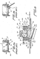
An example of such a conventional or typical cargo air
bag inflation valve assembly is disclosed within
US-A-5,082,244. As disclosed within FIGURE 1, which
corresponds in part to FIGURE 5 of the noted patent, the
air bag is disclosed at 10 and is seen to comprise first
and second oppositely disclosed sheets or plies 16,24 with
an inflatable bladder 22 interposed therebetween. An air
bag inflation valve assembly 28 comprises a flange portion
34 which is welded to an interior portion of the plastic
bladder 22, and a tubular valve body 30 which passes
through a hole provided within the sheet 24 so as to
effectively define a fixture external of the air bag 10 for
facilitating inflation of the internal bladder 22 with
compressed air. The valve body 30 has a passageway 32
defined therethrough, and a valve stem 44 is located within
the passageway 32. The lower end portion of the valve stem
44 comprises a valve closure plate 46 which has an annular
portion 48 which is adapted to be seated upon a valve seat
member 36 of the valve body 30. A spring 50 normally biases
the valve stem 44 to its CLOSED position, and the valve
stem 44 is movable to its OPENED position when a force is
imposed upon the end 52 of the valve stem 44 which is
disposed opposite the valve closure plate 46. An inflation
mechanism 54 includes a main body portion 56 within which
there is provided an internally threaded portion 68 for
threaded engagement with an air hose, not shown, by means
of which compressed air can be supplied for inflating the
bladder 22 through means of an axially oriented passageway
66. An annular member 58 is threadedly mounted upon a lower
end portion of the body portion 56 and has a plurality of
detent balls 72 mounted thereon. A collar member 60 is
slidably mounted upon the annular member 58, and an annular
portion 70 also projects axially downwardly from the body
portion 56 for engaging the upper end portion 52 of the
valve stem 44. When the collar member 60 is slidably moved
downwardly with respect to the annular member 58, the
detent balls 72 are forced radially inwardly so as to
effectively lock the inflation mechanism 54 upon the
inflation valve assembly 28, by engaging annular detent
surface 80 defined between inclined surface portions 38,40,
so as to achieve inflation of the bladder 22.
-
While the above inflation valve assembly 28 has proven
to be operationally satisfactory, it can nevertheless be
appreciated that the assembly 28 does comprise a
substantial number of operative components and is therefore
in fact relatively complex. Another conventional or PRIOR
ART filling nozzle or inflation valve assembly for use in
conjunction with the filling of cargo or dunnage air bags,
sacks, containers, or the like, and which is relatively
simple in structure and operation, is disclosed within
US-A-5,651,403. As can be appreciated from FIGURE 2, which
substantially corresponds to FIGURE 1 of this patent, it is
seen that the entire closure assembly 1 comprises a filling
nozzle 5 with valve holder means 18 for holding or
receiving a closable valve 7, and a flanged member 10 which
includes a cylindrical or tubular portion 11 and a plate-shaped
portion 12 which is adapted to be fixedly secured to
the interior of the inflatable dunnage air bag or
container. The filling nozzle 5 includes a lower portion 47
which is snap-connected onto the flanged member 10 as at
49, and the upper portion of the filling nozzle 5, upon
which the closable valve 7 and valve holder 18 are
disposed, is pivotally mounted upon the flanged member 10
by means of a hinge member 50. When the container or
dunnage air bag is to be closed, the filling nozzle 5
sealingly engages the flanged member 10 and is retained at
such position by means of a snapping hook 30 snap-engaging
a snap- connection 14,31 provided upon the flanged member
10. When the container or dunnage air bag is to be inflated
with compressed air, a bayonet lock 37 is adapted to be
mated with a gripping coupling through which compressed air
may be delivered to the assembly 1.
-
While this system is readily appreciated to be
substantially simpler in construction as compared to the
first system it is nevertheless desirable to construct an
inflation valve assembly which simplifies the overall
structure of the assembly still further. In addition, it is
also desirable to utilize a suitable implement in
conjunction with the valve assembly which not only readily
facilitates the inflation of the dunnage air bag, sack,
container, or the like, but likewise facilitates the
deflation of the dunnage air bag, sack, container, or the
like, so as to not only efficiently secure cargo, but in
addition, to efficiently enable the unloading of the cargo
from the particular cargo holds of the particular truck,
airplane, ship, or railroad transportation facility. These
operational requirements seem to have been met by means of
still another conventional or PRIOR ART air valve mechanism
for an inflatable device which is disclosed within US-A-6,138,711.
-
As disclosed within FIGURES 3a and 3b, which
substantially correspond to FIGURES 3 and 4 of this patent,
the air valve mechanism comprises a valve block 10 which is
seen to include an upper body portion 11, a lower body
portion 13, and a radially outwardly extending annular
mounting flange member 12 interposed between the upper and
lower body portions 11,13 for facilitating the mounting of
the valve mechanism upon an external wall portion of the
object to be inflated. A radially inwardly extending
annular flange member 14 is also interposed between the
upper and lower body portions 11,13, and a mounting or
positioning portion 141 is integral with one side of the
flange member 14 for mounting a valve flap 20 thereon. The
valve flap 20 comprises a deformable rubber flap which is
mounted within the lower body portion 13 beneath the
radially inwardly extending flange member 14 and includes
a folding groove 23 which effectively divides the valve
flap 20 into a fixed flap portion mounted upon the mounting
or positioning portion 141 by means of a fastening device
40, and a free flap portion which is movable between OPEN
and CLOSED positions as seen in FIGURES 3b and 3a,
respectively. A pair of locating plates 131 project
downwardly from substantially diametrically opposite sides
of the lower body portion 13, and it is noted that the
diametrical or chordal extent or distance defined between
the locating plates 131 is less than the diametrical extent
of the valve flap 20. Accordingly, when the valve flap 20
is moved by compressed air from the CLOSED position to the
OPENED position, it must deform in order to pass beyond the
locating plates 131. In a similar manner, in order to move
the valve flap 20 from the OPENED position back to its
CLOSED position, the valve flap 20 is necessarily provided
with a finger rod 21 so as to again cause deformation of
the valve flap 20 and pull the same beyond the locating
plates 131. It can therefore be appreciated that while the
valve mechanism of Lung-Pa appears to be operatively
satisfactory, potential is present for the jamming of the
valve flap 20 within the mechanism. In addition, the valve
mechanism of Lung-Pa obviously does not lend itself to
automatic inflation and deflation operational modes or
techniques in view of the need for operator assistance in
moving the valve flap 20 from the OPENED position to the
CLOSED position.
-
A need therefore exists in the art for a new and
improved cargo air bag inflation and deflation system which
is relatively simple in structure, and which facilitates
both the automatic inflation and deflation of the cargo or
dunnage air bag so as to efficiently enable the securing of
loaded cargo within cargo holds as well as to efficiently
enable the unloading of the secured cargo from the cargo
holds.
-
Accordingly, it is an object of the present invention
to provide a new and improved cargo or dunnage air bag
inflation and deflation system for use in conjunction with
the securing of cargo loads within transportation facility
cargo holds as well as the unloading of the secured cargo
loads from the cargo holds of the transportation facility.
-
Another object of the present invention is to provide
a new and improved cargo or dunnage air bag inflation and
deflation system, for use in conjunction with the securing
of cargo loads within transportation facility cargo holds
as well as the unloading of the secured cargo loads from
the cargo holds of the transportation facility, wherein the
new and improved system overcomes the various operational
disadvantages and drawbacks characteristic of PRIOR ART
dunnage or air bag inflation systems.
-
An additional object of the present invention is to
provide a new and improved cargo or dunnage air bag
inflation and deflation system, for use in conjunction with
the securing of cargo loads within transportation facility
cargo holds as well as the unloading of the secured cargo
loads from the cargo holds of the transportation facility,
wherein the system is relative simple in structure.
-
A further object of the present invention is to
provide a new and improved cargo or dunnage air bag
inflation and deflation system, for use in conjunction with
the securing of cargo loads within transportation facility
cargo holds as well as the unloading of the secured cargo
loads from the cargo holds of the transportation facility,
wherein the system embodies simplified valving structure.
-
A last object of the present invention is to provide
a new and improved cargo or dunnage air bag inflation and
deflation system, for use in conjunction with the securing
of cargo loads within transportation facility cargo holds
as well as the unloading of the secured cargo loads from
the cargo holds of the transportation facility, wherein the
system embodies simplified valving structure as well as an
air gun which is uniquely adapted to be operatively and
fluidically mated with such valving structure so as to be
capable of achieving both inflation of the cargo or dunnage
air bag as well as deflation of the cargo or dunnage air
bag.
-
The foregoing and other objectives are achieved in
accordance with the teachings and principles of the present
invention through the provision of a new and improved cargo
or dunnage air bag inflation and deflation system which
comprises an inflation-deflation valve member, and a cap-type
plug member. The valve member comprises a flapper or
check valve element pivotally mounted within a lower
portion of the valve member so as to permit inflation or
deflation of the cargo or dunnage air bag when the flapper
or check valve element is moved away from its valve seat,
and to substantially maintain the cargo or dunnage air bag
in its inflated state when the flapper or check valve
element is effectively seated upon its valve seat. The cap-type
plug member is removably mounted upon the inflation-deflation
valve member so as to effectively close and seal
the valve assembly when the cap-type plug assembly is
mounted upon the valve member so as to be disposed at its
CLOSED state, and which effectively uncovers the valve
member when the cap-type plug member is disposed at its
OPENED state. More particularly, when the cap-type plug
member is disposed at its OPENED state so as to effectively
uncover the valve member, a gun-type implement is able to
be structurally and fluidically connected to the valve
assembly so as to either enable or facilitate the inflation
of the cargo or dunnage air bag or to enable or facilitate
the deflation of the cargo or dunnage air bag depending
upon whether a fill-nozzle end portion of the gun is
operatively and fluidically connected to the valve member
or whether an exhaust-nozzle end portion of the gun is
operatively and fluidically connected to the valve member.
-
Particular embodiments in accordance with this
invention will now be described with reference to the
accompanying drawings; in which:-
- FIGURE 1 is a cross-sectional view of a first PRIOR
ART cargo air bag inflation valve assembly as mounted upon
an inflatable cargo air bag;
- FIGURE 2 is a cross-sectional view of a second PRIOR
ART cargo air bag inflation valve assembly to be mounted
upon an inflatable cargo air bag;
- FIGURES 3a and 3b are cross-sectional views of a third
PRIOR ART inflation valve assembly to be mounted upon an
object to be inflated, wherein the valve assembly is
respectively disclosed in its CLOSED and OPENED positions;
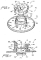
- FIGURE 4 is an exploded perspective view of a first
embodiment of cargo or dunnage air bag inflation-deflation
valve member and cap-type plug assembly in accordance with
present invention;
- FIGURE 5 is an assembled perspective view of the cargo
or dunnage air bag inflation-deflation valve member and
cap-type plug assembly shown in FIGURE 4;
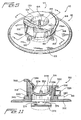
- FIGURE 6 is a cross-sectional view of the cargo or
dunnage air bag inflation-deflation valve member and cap-type
plug assembly shown in FIGURE 5 as taken along the
lines 6-6 of FIGURE 5 and, in addition, shown as mounted
upon an interior portion of an inflatable cargo or dunnage
air bag;
- FIGURE 7 is a cross-sectional view of the cargo or
dunnage air bag inflation-deflation valve member and cap-type
plug assembly shown in FIGURE 5 as taken along the
lines 7-7 of FIGURE 5;
- FIGURE 8 is an exploded perspective view of an
inflation-deflation gun for operative use in conjunction
with the cargo or dunnage air bag inflation-deflation valve
member shown in FIGURES 4-7;
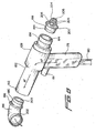
- FIGURE 9 is a side elevational view of the inflation-deflation
gun schematically illustrating the operative use
of each operative end of the gun in conjunction with a
cargo or dunnage air bag inflation-deflation valve member
shown in FIGURES 4-7;
- FIGURE 10 is a cross-sectional view, of the inflation-deflation
gun schematically illustrating the operative use
of each operative end of the gun in con-junction with a
cargo or dunnage air bag inflation-deflation valve member
shown in FIGURES 4-7, as taken along the lines 10-10 of
FIGURE 9; and,
- FIGURE 11 is a cross-sectional view similar to that of
FIGURE 7 showing, however, a second embodiment of a cargo
or dunnage air bag inflation-deflation valve member and
cap-type plug assembly in accordance with the present
invention.
-
-
Referring now to the drawings, and more particularly
to FIGURES 4-7 thereof, a first embodiment of a new and
improved cargo or dunnage air bag inflation-deflation valve
member and cap-type plug assembly, constructed in
accordance with the principles and teachings of the present
invention and showing the cooperative parts thereof, is
disclosed and is generally indicated by the reference
character 110. As can be readily appreciated, the cargo or
dunnage air bag inflation-deflation valve member and cap-type
plug assembly 110 is seen to comprise an inflation-deflation
valve member 112, and a cap-type plug or closure
member 114, which is adapted to be mounted, in a
repetitively removable manner, upon the inflation-deflation
valve member 112 when neither an inflation or deflation
operative cycle is being performed in connection with an
inflatable cargo or dunnage air bag 116, which is shown in
FIGURE 6, so as to sealingly close the inflatable cargo or
dunnage air bag 116 under such non-inflation, non-deflation
operative conditions. The inflation-deflation valve member
112 is seen to comprise an axially central, vertically
upstanding tubular housing or wall portion 118 defining an
axially extending air passageway 120, and a radially
outwardly extending flange portion 122 integrally connected
to the lowermost end portion of the tubular wall or housing
portion 118 as can best be appreciated from FIGURES 6 and
7. More particularly, a wall portion of the air bag 116 is
provided with a hole or aperture 124, and the outer or
external surface 126 of the radially outwardly extending
flange portion 122 of the inflation-deflation valve member
112 is adapted to be heat-sealed or welded to an interior
surface portion of the inflatable bladder of the air bag
116 such that the tubular housing or wall portion 118 of
the inflation-deflation valve member 112 projects outwardly
through the hole or aperture 124 so as to be externally
accessible to a source of high-pressure or compressed air
which is operatively connected to a gun 128 as is disclosed
within FIGURES 8-10 and as will be discussed further
hereinafter.
-
As has been noted hereinbefore, the cap-type plug or
closure member 114 is adapted to be mounted, in a
repetitively removable manner, upon the inflation-deflation
valve member 112 when neither an inflation or deflation
operative cycle is being performed in connection with the
inflatable cargo or dunnage air bag 116 so as to sealingly
close the inflatable cargo or dunnage air bag 116 under
such non-inflation, non-deflation operative conditions.
More particularly, the cap-type plug or closure member 114
is fabricated from a suitable rubber, thermoplastic, or
other relatively compliant material, and it is seen that
the cap-type plug or closure member 114 comprises an upper,
horizontally disposed, annularly configured planar support
member 130, a first radially outer, circumferentially
extending peripheral wall 132 projecting axially downwardly
from an undersurface portion of the upper planar support
member 130 located near the outer peripheral edge portion
thereof, and a second radially inner, circumferentially
extending wall 134 which also projects axially downwardly
from an undersurface portion of the upper planar support
member 130 located near the inner peripheral edge portion
thereof. The second radially inner, circumferentially
extending wall 134 is radially spaced from the first
radially outer, circumferentially extending peripheral wall
132 so as to define an annular space 136 there-between, and
in this manner, as can best be appreciated from FIGURES 6
and 7, when the cap-type plug or closure member 114 is
mounted upon the inflation-deflation valve member 112, the
upwardly extending tubular housing or wall portion 118 of
the inflation-deflation valve member 112 will be disposed
and accommodated within the annular space 136 defined
between the first radially outer and second radially inner
circumferentially extending walls 132,134.
-
The inner peripheral, circumferentially extending
surface portion of the second radially inner
circumferentially extending wall 134 defines a central
recess or pocket 138 which extends axially downwardly from
the upper planar support member 130, and a substantially
horizontally extending structural member 140, having a
substantially circular cross-sectional configuration, is
integrally formed upon a lower end portion of the second
radially inner, circumferentially extending wall 134. In
this manner, the substantially horizontally extending
structural member 140 serves as a bottom end wall which
closes the recess or pocket 138 and thereby effectively
completes the structure of the cap-type plug member 114. In
order to assist in securing the cap-type plug or closure
member 114 upon the upper end portion of the tubular
housing or wall portion 118 of the inflation-deflation
valve member 112 in a snap-fitting manner, it is seen
further, from FIGURES 4,6, and 7, that the outer wall
surface of the tubular housing or wall portion 118 of the
inflation-deflation valve member 112 is integrally provided
with a circumferentially extending convex band or ridge
member 142, while the inner wall surface of the first
radially outer, circumferentially extending peripheral wall
132 of the cap-type plug or closure member 114 is
correspondingly provided with a circumferentially extending
concave recess 144 for accommodating the ridge member 142.
In a similar manner, the inner peripheral wall surface of
the tubular housing or wall portion 118 of the inflation-deflation
valve member 112 is provided with a
circumferentially extending concave recessed region 146,
and the external peripheral wall surface of the second
radially inner, circumferentially extending wall 134 of the
cap-type plug or closure member 114 is correspondingly
provided with a circumferentially extending convex band or
ridge member 148 which is adapted to be accommodated within
the recessed region 146 when the cap-type plug or closure
member 114 is snap-fitted upon the inflation-deflation
valve member 112. It is to be further appreciated that the
substantially horizontally extending structural member 140
comprises an axially central, horizontally disposed planar
section 150 which is integrally connected to the second
radially inner, circumferentially extending wall 134 of the
cap-type plug or closure member 114 by means of an upwardly
inclined annular wall portion 152.
-
In addition, a plurality of radially extending rib
members 154 structurally reinforce the annular wall portion
152, and it is particularly noted that the lower radially
inner ends of the rib members 154 are connected to the
planar section 150, while the upper radially outer ends of
the rib members 154 are connected to the second radially
inner, circumferentially extending wall 134 at elevational
levels which substantially correspond to the location of
the circumferentially extending convex band or ridge member
148 of the cap-type plug or closure member 114. In this
manner, when the cap-type plug or closure member 114 is
snap-fittingly mounted upon the inflation-deflation valve
member 112, and the interior of the cargo or dunnage air
bag 116 is inflated, the air pressure within the inflated
cargo or dunnage air bag 116 will act upon the undersurface
portion of the axially central, horizontally disposed
planar section 150 of the cap-type plug or closure member
114 so as to tend to cause or bias the axially central,
horizontally disposed planar section 150 upwardly.
Correspondingly, forces will be transmitted by means of the
rib members 154 toward the second radially inner,
circumferentially extending wall 134 of the cap-type plug
or closure member 114 so as to effectively ensure the tight
disposition and sealing of the circumferentially extending
convex band or ridge member 148 of the cap-type plug or
closure member 114 within the circumferentially extending
concave recessed region 146 of the inflation-deflation
valve member 112.
-
It is further noted that, in connection with the snap-fitted
mounting of the cap-type plug or closure member 114
upon the inflation-deflation valve member 112, a
substantially upstanding handle or hand-grasping member
156, having a substantially triangularly configured cross-sectional
configuration, as best seen from FIGURE 7, is
integrally formed upon the upper planar support member 130,
and that the handle or member 156 further comprises a
radially outwardly projecting lip portion 158. It can be
appreciated that the member or handle 156, particularly in
conjunction with the lip portion 158, facilitates the
upward lifting, and the downward depression, of the cap-type
plug or closure member 114 with respect to its seated
position upon the inflation-deflation valve member 112
during repetitive dismounting or disassembly, and mounting
or assembly, respectively, of the cap-type plug or closure
member 114 from or upon the inflation-deflation valve
member 112. When the cap-type plug or closure member 114 is
dismounted or disassembled from the inflation-deflation
valve member 112, it is nevertheless desirable to maintain
the cap-type plug or closure member 114 attached to the
inflation-deflation valve member 112 such that the cap-type
plug or closure member 114 does not actually become
separated from the inflation-deflation valve member 112
whereby the cap-type plug or closure member 114 could then
be misplaced or lost.
-
Accordingly, it is further seen that the inflation-deflation
valve member 112 is provided with a plurality of
circumferentially spaced lug members 160 which are
integrally formed at the junction of the inner periphery of
the flange portion 122 and the lower end portion of the
tubular housing or wall portion 118, and that one of the
lug members 160 is provided with a through-aperture 162. A
tether member 164 is integrally provided upon the upper
planar support member 130 and is attached thereto at a
proximal end portion 166 which is located substantially
diametrically opposite the handle or hand-grasping member
156. The free or distal end portion of the tether member
164 is provided with a substantially triangularly-configured
head section 168 which is adapted to be inserted
through the aperture 162 defined within the noted lug
member 160. Accordingly, when the cap-type plug or closure
member 114 is to be initially mounted or assembled upon the
inflation-deflation valve member 112, the head section 168
of the tether member 164 is inserted through the aperture
162 of the noted lug member 160 whereby the base portion
170 of the head section 168, after being compressed and
forced through the aperture 162, will effectively prevent
passage of the triangular head section 168 back through the
aperture 162 in a reverse direction or retrograde manner.
Therefore, the cap-type plug or closure member 114 is
securely attached to the inflation-deflation valve member
112 and can be subsequently sealingly positioned upon the
inflation-deflation valve member 112 when desired, that is,
for example, either for cargo or dunnage air bag storage
purposes, or subsequent to the completion of an air bag
inflation procedure, operation, or cycle in order to
maintain the cargo or dunnage air bag in its inflated
condition or state.
-
Continuing further, and in accordance with another
unique feature of the present invention, a flapper valve or
check valve element 172 is operatively associated with the
lower end of the air passageway 120 defined within and
extending axially through the vertically upstanding tubular
housing or wall portion 118 of the inflation-deflation
valve member 112. More particularly, the flapper valve or
check valve element 172 comprises, in effect, a plate-type
member which is integrally formed with the inflation-deflation
valve member 112, and as can best be appreciated
from FIGURES 6 and 7, a proximal end portion of the flapper
valve or check valve element 172 is integrally connected to
a lower, inner peripheral region of the vertically
upstanding tubular housing or wall portion 118 by means of
a pair of arcuately spaced living hinge mechanisms 174,174.
As noted within FIGURE 6, the air passageway 120, defined
within and extending axially through the vertically
upstanding tubular housing or wall portion 118 of the
inflation-deflation valve member 112, has a predetermined
diametrical extent D, and the f lapper valve or check valve
component 172 likewise has a predetermined diametrical or
cross-sectional extent L wherein the diametrical or cross-sectional
extent L of the flapper valve or check valve
element 172 is slightly greater than the diametrical extent
D of the air passageway 120.
-
The reason for this is that when the interior of the
dunnage or cargo air bag 116 is pressurized and inflated,
it is desirable that the air pressure within the dunnage or
cargo air bag 116 will tend to close the flapper valve or
check valve element 172 with respect to the lower end
portion of the air passageway 120 such that the flapper
valve or check valve element 172 is positioned upon its
valve seat 176 which is defined by means of the annular
wall portion of the inflation-deflation valve member 112
which is formed at the juncture of the vertically
upstanding tubular housing or wall portion 118 and the
radially outwardly extending flange portion 122. In this
manner, the seating of the flapper valve or check valve
element 172 upon its valve seat 176 effectively prevents
any massive leakage of the pressurized air out from the
interior portion of the dunnage or cargo air bag prior to
the operator having the opportunity to sealingly close the
air passageway 120 of the inflation-deflation valve member
112 by sealingly mounting the cap-type plug or closure
member 114 thereon. However, it is likewise desirable that
the flapper valve or check valve element 172 does not
become trapped or otherwise stuck within the lower end
portion of the air passageway 120 so as to always be
capable of freely performing its valving functions in
connection with the inflation of the dunnage or cargo air
bag 116, the deflation of the dunnage or cargo air bag 116,
and the maintenance of the inflated state or condition of
the dunnage or cargo air bag 116. Accordingly, it can be
appreciated that when the flapper valve or check valve
element 172 is moved toward its CLOSED position, the outer
periphery of the flapper valve or check valve element 172
will abut or be disposed in contact with the valve seat
portion 176 of the inflation-deflation valve member 112,
however, the f lapper valve or check valve element 172 will
not actually enter or be disposed internally within the
lower end portion of the air passageway 120.
-
With reference now being made to FIGURES 8-10, the new
and improved air gun implement 128, as constructed in
accordance with the principles and teachings of the present
invention, and which is adapted to be used in conjunction
with the inflation-deflation valve member 112 for achieving
inflation and deflation of the dunnage or cargo air bag
116, will now be discussed and described. More
particularly, the air gun implement 128 may comprise, for
example, a VORTEC Model 2100/BPS type gun which is
available from ITW VORTEC in Cincinnati, OHIO, USA, and is
seen to include an upstanding handle 178 to which an air
hose 180 is operatively connected. A trigger member 181 is
reciprocably mounted upon the upper end portion of the
handle 178 so as to control a suitable valve mechanism, not
shown, between a CLOSED state at which the incoming
pressurized air from hose 180 is effectively prevented from
flowing through the air gun implement 128, and an OPENED
state at which the incoming pressurized air from hose 180
is permitted to flow through the air gun implement 128. A
barrel section 182 of the air gun implement 128 is
integrally mounted atop the handle 178, and an air flow-through
passageway 184, having a predetermined internal
diametrical extent, is defined within the barrel section
182 so as to permit air flow therethrough as shown by means
of the fluid flow arrows AF illustrated in FIGURE 8.
-
As viewed in FIGURES 8-10, the left open end portion
of the barrel section 182 of the air gun implement 128 is
adapted to have a tubular fill nozzle member 186 fixedly
mounted therein, while the right open end portion of the
barrel section 182 of the air gun implement 128 is
similarly adapted to have a tubular exhaust nozzle member
188 fixedly mounted therein. The upstream end portion 190
of the fill nozzle member 186, as considered in the
direction of air flow as denoted by means of the fluid flow
arrows AF, has a predetermined external diametrical extent
which is slightly smaller than the predetermined internal
diametrical extent of the barrel flow-through passageway
184 so as to permit the same to be disposed internally
within the downstream end portion 192 of the barrel section
182, while the downstream end portion 194 of the exhaust
nozzle member 188 similarly has a predetermined external
diametrical extent which is likewise slightly smaller than
the predetermined internal diametrical extent of the barrel
flow-through passageway 184 so as to permit the same to be
disposed internally within the upstream end portion 196 of
the barrel section 182. The upstream end portion 190 of the
fill nozzle member 186 is provided with an annular flange
198 which is adapted to abut, engage, and be seated upon
the open end wall of the downstream end portion 192 of the
barrel section 182 when the fill nozzle member 186 is
mounted within the downstream end portion 192 of the barrel
section 182, as can best be appreciated from FIGURES 8 and
10, and the downstream end portion 194 of the exhaust
nozzle member 188 is similarly provided with an annular
flange 200 which is likewise adapted to abut, engage, and
be seated upon the open end wall of the upstream end
portion 196 of the barrel section 182 when the exhaust
nozzle member 188 is mounted within the upstream end
portion 196 of the barrel section 182.
-
In a similar manner, the downstream end portion 202 of
the fill nozzle member 186 has a predetermined internal
diametrical extent which is slightly larger than the
external diametrical extent of the vertically upstanding
tubular housing or wall portion 118 of the inflation-deflation
valve member 112 so as to permit the air gun
implement 128, and in particular, the fill nozzle member
186 thereof, to be fluidically connected to the inflation-deflation
valve member 112 as illustrated within the left
side portion of FIGURE 10. As a result of such fluidic
connection defined between the fill nozzle member 186 of
the air gun implement 128 and the inflation-deflation valve
member 112, and upon actuation of the trigger member 181 of
the air gun implement 128, high-pressure air from air hose
180 will flow through the passageway 184 of the air gun
implement 128 and the passageway 203 of the fill nozzle
member 186 thereby impinging upon the flapper valve or
check valve element 172 so as to thereby unseat the same
from its valve seat 176 and permit inflation of the dunnage
or cargo air bag 116. Alternatively, it is likewise noted
that the upstream end portion 204 of the exhaust nozzle
member 188 has a predetermined external diametrical extent
which is slightly less than the internal diametrical extent
of the vertically upstanding tubular housing or wall
portion 118 of the inflation-deflation valve member 112 so
as to permit the air gun implement 128, and in particular,
the exhaust nozzle member 188 thereof, to be fluidically
connected to the inflation-deflation valve member 112 as
illustrated within the right side portion of FIGURE 10.
-
More particularly, the upstream end portion 204 of the
exhaust nozzle member 188 comprises a nosepiece 206 which
is integrally connected to the annular flange member 200 by
means of a plurality of circumferentially spaced spiderlegs
208. consequently, when it is desired to deflate the
dunnage or cargo air bag 116, the exhaust nozzle member 188
is mated with, inserted into, and internally disposed
within the inflation-deflation valve member 112. As can
best be appreciated from FIGURES 9 and 10, the nosepiece
206 will therefore engage the flapper valve or check valve
member 172 thereby unseating the valve element 172, and
maintaining the same away, from its valve seat 176 so as to
establish fluidic communication between the interior of the
dunnage or cargo air bag 116 and the passageway 210 of the
exhaust nozzle member 188 as well as with the flow-through
passageway 184 of the air gun implement 128. Accordingly,
upon actuation of the trigger member 181 of the air gun
implement 128, high pressure air from air hose 180 will
flow through passageway 184 of air gun implement 128, as
well as through passageway 203 of fill nozzle member 186,
so as to exhaust to atmosphere, while at the same time, or
concomitantly therewith, air will be sucked out of or
exhausted from the interior of the dunnage or cargo air bag
116 so as to likewise be exhausted past flapper valve or
check valve element 172, between spider-legs 208, through
exhaust nozzle passageway 10, gun barrel passageway 184,
and fill nozzle passageway 203.
-
With reference lastly being made to FIGURE 11, a
second embodiment of a new and improved cargo or dunnage
air bag inflation-deflation valve member and cap-type plug
assembly, constructed in accordance with the principles and
teachings of the present invention and showing the
cooperative parts thereof, is disclosed and is generally
indicated by the reference character 310. It is to be noted
that the structural components comprising the second
embodiment of the dunnage or cargo air bag inflation-deflation
valve member and cap-type plug assembly 310 are
substantially the same as those of the first embodiment of
the dunnage or cargo air bag inflation-deflation valve
member and cap-type plug assembly 110, except as will be
noted hereinafter, and therefore, a detailed description of
such second embodiment of the dunnage or cargo air bag
inflation-deflation valve member and cap-type plug assembly
310 will be omitted for brevity purposes. Accordingly, it
is further noted in conjunction with the description of the
second embodiment of the dunnage or cargo air bag
inflation-deflation valve member and cap-type plug assembly
310 that the various structural components thereof, which
are similar to the various structural components of the
first embodiment of the dunnage or cargo air bag inflation-deflation
valve member and cap-type plug assembly 110 are
denoted by means of corresponding reference characters
except that they are within the 300 series. More
particularly, as can be seen from FIGURE 11, the only
significant difference between the second embodiment of the
dunnage or cargo air bag inflation-deflation valve member
and cap-type plug assembly 310 and that of the first
embodiment of the dunnage or cargo air bag inflation-deflation
valve member and cap-type plug assembly 110
resides in the fact that in lieu of the cap-type plug or
closure member 114 being connected to the inflation-deflation
valve member 112 by means of tether 164, an
annular ring member 333 is adapted to be mounted upon the
external peripheral surface of the vertically upstanding
tubular housing or wall portion 318 of the inflation-deflation
valve member 312, and an external peripheral
portion of the radially outer, circumferentially extending
peripheral wall 332 of the cap-type plug or closure member
314 is integrally connected to the annular ring member 333
by means of a living hinge element 335. In this manner, as
was the case of the first embodiment of the dunnage or
cargo air bag inflation-deflation valve member and cap-type
plug assembly 110, the cap-type plug or closure member 314
is securely fixed to the inflation-deflation valve member
312 so as not to be separated therefrom and thereby
misplaced or lost.
-
Thus, it may be seen that in accordance with the
principles and teachings of the present invention, there
has been developed a new and improved inflation-deflation
valve member and cap-type plug assembly wherein the same
comprises a relatively simple flapper valve or check valve
element incorporated within the inflation-deflation valve
member. In addition, a new and improved air gun implement
has a fill nozzle member and an exhaust valve member
operatively mounted upon opposite ends thereof so as to be
able to fluidically and structurally interact with the
flapper valve or check valve element and thereby achieve
inflation and deflation of the dunnage or cargo air bag.