EP1367750A1 - Testing network communications - Google Patents

Testing network communications Download PDF

Info

Publication number
EP1367750A1
EP1367750A1 EP02254839A EP02254839A EP1367750A1 EP 1367750 A1 EP1367750 A1 EP 1367750A1 EP 02254839 A EP02254839 A EP 02254839A EP 02254839 A EP02254839 A EP 02254839A EP 1367750 A1 EP1367750 A1 EP 1367750A1
Authority
EP
European Patent Office
Prior art keywords
tester
test data
addresses
test
communications
Prior art date
Legal status (The legal status is an assumption and is not a legal conclusion. Google has not performed a legal analysis and makes no representation as to the accuracy of the status listed.)
Withdrawn
Application number
EP02254839A
Other languages
German (de)
French (fr)
Inventor
James Holmes Elliott
Martin Curran-Gray
Gordon Old
Kevin Douglas Mccall
Current Assignee (The listed assignees may be inaccurate. Google has not performed a legal analysis and makes no representation or warranty as to the accuracy of the list.)
Agilent Technologies Inc
Original Assignee
Agilent Technologies Inc
Priority date (The priority date is an assumption and is not a legal conclusion. Google has not performed a legal analysis and makes no representation as to the accuracy of the date listed.)
Filing date
Publication date
Priority claimed from EP02253794A external-priority patent/EP1367749A1/en
Application filed by Agilent Technologies Inc filed Critical Agilent Technologies Inc
Priority to EP02254839A priority Critical patent/EP1367750A1/en
Priority to JP2003134807A priority patent/JP2004032725A/en
Priority to CN03123787A priority patent/CN1462132A/en
Priority to US10/448,540 priority patent/US20030223376A1/en
Publication of EP1367750A1 publication Critical patent/EP1367750A1/en
Withdrawn legal-status Critical Current

Links

Images

Classifications

    • HELECTRICITY
    • H04ELECTRIC COMMUNICATION TECHNIQUE
    • H04LTRANSMISSION OF DIGITAL INFORMATION, e.g. TELEGRAPHIC COMMUNICATION
    • H04L43/00Arrangements for monitoring or testing data switching networks
    • H04L43/50Testing arrangements
    • HELECTRICITY
    • H04ELECTRIC COMMUNICATION TECHNIQUE
    • H04JMULTIPLEX COMMUNICATION
    • H04J3/00Time-division multiplex systems
    • H04J3/02Details
    • H04J3/14Monitoring arrangements
    • HELECTRICITY
    • H04ELECTRIC COMMUNICATION TECHNIQUE
    • H04JMULTIPLEX COMMUNICATION
    • H04J3/00Time-division multiplex systems
    • H04J3/16Time-division multiplex systems in which the time allocation to individual channels within a transmission cycle is variable, e.g. to accommodate varying complexity of signals, to vary number of channels transmitted
    • H04J3/1605Fixed allocated frame structures
    • H04J3/1611Synchronous digital hierarchy [SDH] or SONET
    • HELECTRICITY
    • H04ELECTRIC COMMUNICATION TECHNIQUE
    • H04JMULTIPLEX COMMUNICATION
    • H04J2203/00Aspects of optical multiplex systems other than those covered by H04J14/05 and H04J14/07
    • H04J2203/0001Provisions for broadband connections in integrated services digital network using frames of the Optical Transport Network [OTN] or using synchronous transfer mode [STM], e.g. SONET, SDH
    • H04J2203/0062Testing
    • HELECTRICITY
    • H04ELECTRIC COMMUNICATION TECHNIQUE
    • H04LTRANSMISSION OF DIGITAL INFORMATION, e.g. TELEGRAPHIC COMMUNICATION
    • H04L69/00Network arrangements, protocols or services independent of the application payload and not provided for in the other groups of this subclass
    • H04L69/30Definitions, standards or architectural aspects of layered protocol stacks
    • H04L69/32Architecture of open systems interconnection [OSI] 7-layer type protocol stacks, e.g. the interfaces between the data link level and the physical level
    • H04L69/322Intralayer communication protocols among peer entities or protocol data unit [PDU] definitions
    • H04L69/323Intralayer communication protocols among peer entities or protocol data unit [PDU] definitions in the physical layer [OSI layer 1]

Definitions

  • This invention relates to methods and apparatus for testing communication in a network, for example Ethernet tributary data streams which are merged for transmission over SONET or SDH (Synchronous Digital Hierarchy) networks.
  • a network for example Ethernet tributary data streams which are merged for transmission over SONET or SDH (Synchronous Digital Hierarchy) networks.
  • a third option is to use existing SONET/SDH networks to carry payload comprising packet data, collected and distributed for example via tributary data streams implemented using Ethernet technology. This involves a smaller capital outlay, continues to generate (or even increase) revenue from existing network installations, and does not affect continuity of service for existing customers whose traffic is carried over the SONET/SDH network.
  • a tester for testing communication in a network which carries data frames between communications ports having respective addresses comprising:
  • a tester for testing communication in a network which carries data frames between communications ports having respective addresses comprising:
  • a tester for testing communication in a network which carries data frames between communications ports having respective addresses comprising:
  • This equipment receives tributary signals in their native formats (in the present case Ethernet frames) and either creates SONET/SDH frames by combining the tributary signals from multiple sources (terminal multiplexer) or inserts portions of a tributary signal into respective sections of the payload envelope of successive existing frames (add-drop multiplexer).
  • the multiplexers 16 and 18 are interconnected over SONET/SDH links either directly or via digital crossconnect equipment 20.
  • the details of SONET/SDH frame structure and of operation of equipment such as terminal multiplexers, add-drop multiplexers and cross-connects are well know to those skilled in the art and need not be discussed here.
  • test signals Ethernet data frames
  • a test set 22 connected to the OADM 16 may be used to inject test frames into the network 10 for transmission to another test set 24 connected to the terminal multiplexer 18.
  • testing of a system including Ethernet components is complicated by the need to specify one or more port addresses for each Ethernet component.
  • the addressing scheme by which data frames are routed to their intended destination over an Ethernet LAN involves the allocation to each Ethernet interface equipment (plug-in card or integral circuitry) of a globally unique 12-digit (6-byte) hexadecimal station address such as 08:00:07:A9:B2:FC.
  • a test engineer needs to transmit test data over the path from OADM 16 via the SONET/SDH network 10 to the terminal multiplexer 18, it has previously been necessary for the engineer to specify several such addresses for the test sets 22 and 24 at each end of the path. Given the format of these addresses this is a tedious task which is prone to error.
  • a predefined set of Ethernet station addresses are permanently stored and used selectively in both the test sets 22 and 24 to determine the destination addresses of Ethernet frames transmitted by the test sets. These station addresses are drawn from those allocated in accordance with Ethernet practice to the manufacturer of the test sets. Typically the set of addresses is the same for all examples of the same test set model, but different for different models. Selection of particular combinations of addresses in each test set is co-ordinated by the test sets in accordance with user selection of one of several predefined test modes, as described below. In addition, to maintain full flexibility of operation the user is able to configure all Ethernet addresses and related parameters individually, to cater for circumstances where the predefined test modes are not appropriate.
  • the Ethernet ports 26 are coupled to a processor 28 which co-ordinates operation of the test set 22 in accordance with software program instructions stored in a memory 30.
  • Test data to be transmitted via the Ethernet ports 26 are generated in a test data generator 32, for example using a pseudo-random binary sequence (PRBS) generator, and assembled with appropriate Ethernet MAC headers (described below) and check data to produce Ethernet frames.
  • PRBS pseudo-random binary sequence
  • test data in Ethernet frames received via the Ethernet ports 26 are extracted by the processor 28 from the frames and supplied to a test data analyser 34 for validation.
  • the functional requirements of the user of the test set and the results of tests performed are communicated via a user interface 36 (e.g. a display and input device such as a keyboard) controlled by the processor 28.
  • a user interface 36 e.g. a display and input device such as a keyboard
  • the Ethernet frames assembled by the test data generator 32 have a format shown in Figure 3, which in most respects conforms to the format of normal Ethernet frames.
  • Each such frame starts with Media Access Control (MAC) information, such as a preamble, start-of-frame delimiter, destination address, source address and frame length/type indicator.
  • MAC Media Access Control
  • the client data or payload comprises PRBS test data generated by the test data generator 32, followed by three fields of four bytes each of test set data 38. These three fields contain:
  • test sets 22 and 24 provide four principal predefined test modes: Loopback (2-port), End-to-end, Loopback (1-port) and Loop-thru.
  • Each test set stores the same overall set of Ethernet addresses which can be selectively allocated to different ones of the interface ports 26 in the test set and selectively included in Ethernet frames transmitted by different ports 26 in that or another test set. For the purposes of this description four of these addresses will be identified as Address A, Address B, Address X and Address Y.
  • test Set 1 originating set
  • Test Set 2 receiving/loop-back set
  • Addresses A and B are associated with the test set's ports 1 and 2
  • Addresses X and Y are associated with those ports.
  • the selection of addresses for inclusion as destination address in frames transmitted from each port for each of the predefined test modes is specified in the table below.
  • this test mode requires two Ethernet ports to be provided for testing at the network element 18, and the provision of two duplex links within the SONET/SDH network.
  • VPN Virtual Private Network
  • VPN Virtual Private Network
  • test set 22 configured as Test Set 1
  • test set 24 configured as Test Set 2.
  • the test set 22 transmits from its port 1 Ethernet frames containing Address X of port 1 of the test set 24 as the destination address; likewise it transmits from port 2 frames containing Address Y of port 2 of the test set 24 as the destination address.
  • frames transmitted from ports 1 and 2 of the test set 24 are addressed respectively to Addresses A and B of ports 1 and 2 of the test set 22.
  • the two test sets can exchange Ethernet frames over the network and check them for correct operation of the network.
  • Loopback (1-port)/Loop-thru modes are intended for use together, with a test set that is configured as Test Set 1 (the test set 22 in Figure 6) in Loopback (1-port) mode, and the test set that is configured as Test Set 2 (the test set 24) being in Loop-thru mode.
  • the destination address for Ethernet frames sent from port 1 of the test set 22 is the same as in End-to-End mode, i.e. Address X of port 1 of the test set 24.
  • the test set 24 is not arranged for independent generation of its own Ethernet frames.
  • the test set 22 receives back on port 1 the frames it has transmitted from that port.
  • a loopback test can be accomplished using just one port on each test set and with a single duplex link in the SONET/SDH network, irrespective of the specific implementation of Ethernet in use (e.g. with auto-negotiation).
  • additional ports on the test sets 22 and 24 can be used to send additional test frames on a round trip through different paths across the network, for example between the ports 2 of the test sets as indicated in dashed line in Figure 6.
  • the test set 24 retransmits all frames it receives.
  • a problem can arise if that switch is reset or is in 'learn' mode (i.e. discovering the identity of other Ethernet devices to which it is connected).
  • any frame received on any port of the switch will be transmitted on all the switch's other ports (so-called flooding) in an attempt to ensure that it will find its intended destination despite the absence of precise information in the switch about how to route the frame.
  • flooding in an attempt to ensure that it will find its intended destination despite the absence of precise information in the switch about how to route the frame.
  • there is an absence of the normal filtering which ensures that a port on the test set 24 receives only frames intended for it.
  • each port of the test set 24 receiving flooded frames from the switch will swap the source and destination addresses of all these flooded frames and return them to the switch.
  • the switch will then see traffic on all ports with misleading apparent source addresses, which will confuse the switch's control software and prevent it from resolving its table of destination addresses versus ports.
  • test set 24 can be provided with two options for operation in Loop-thru mode:
  • test set data 38 included in each Ethernet frame generated by the test sets 22 and 24 include an identification of the physical identity of the source Ethernet port which transmitted that frame.
  • the tests sets 22 and 24 are arranged to look for this identifier in each received Ethernet frame, and extract it when it is found.
  • the extracted identifier is used to control the display of test results on the user interface 36 ( Figure 2), to provide a more meaningful indication of frame source than is possible with Ethernet addresses alone.
  • a user is typically required to consult a table associating Ethernet addresses to individual pieces of test equipment and specific Ethernet ports in them in order to make use of displayed source addresses. Given the length and format of such addresses, this is difficult, time-consuming and prone to misreading.
  • the data stream identifiers are extracted by the processor 28 and associated with the source addresses in the frames. This association enables the test set 24 to display the frame source information on its user interface 36 as "Far end port 1" or "Far end port 2" as appropriate.
  • the "Far end” designation can be determined from the presence in the source address fields of the predefined addresses A and B which are known to both test sets although actively in use at the time only in the test set 22. References to the source of frames generated by the test set 24 (with source addresses X and Y) can likewise be displayed as "Near end port 1" or "Near end port 2".
  • the presence of the data stream identifiers enables a meaningful indication of the frame source information to be provided even if the addressing of the Ethernet test frames has been changed, for example in accordance with a user's specific requirements.

Abstract

A tester (22) for testing communication links in a network which carries data frames between communications ports having respective station addresses includes a plurality of communications ports (1,2,3,4) and a test data generator (32) for generating test data frames to be transmitted via the communications ports. A store (30) holds a plurality of sets of predefined station addresses to be associated with the communications ports. A selector (36) receives an indication of user selection of one of a plurality of test modes of the tester, and selects in accordance with that indication a respective one of the sets of predefined station addresses for association with the communications ports. The selector may also receive an indication of user selection of one of several test modes, and select a respective mode of operation of the communications ports and of the test data generator. In one mode of operation the source and destination station addresses contained in a received data frame are exchanged, and the modified data frame with the exchanged addresses is transmitted back into the network. The test data generator can include a source identifier for determining identity of a tester which transmitted the received test data frames and identity of a communications port via which the test data frames were transmitted; in particular the test data generator may be operative to include within each test data frame it generates an indication of the identity of the communications port from wich the frame is to be transmitted, distinct from the station address of that port.

Description

Technical Field
This invention relates to methods and apparatus for testing communication in a network, for example Ethernet tributary data streams which are merged for transmission over SONET or SDH (Synchronous Digital Hierarchy) networks.
Background Art
Recent years have seen a continuing increase world-wide in the volume of data-related (as distinct from voice-related) telecommunications traffic traversing communications networks. Various approaches are available to accommodate this expanding demand for communications bandwidth. One is to build entirely new networks designed specifically to handle large volumes of data. However, this is not a good economic solution for operators with existing large installed networks which must continue to operated to maximise revenue. Another approach is to install a new packet data network (e.g. using Internet Protocol- IP - or Ethernet or a combination of them), to replace the existing high-capacity SONET/SDH systems used for transmission of voice traffic. To ensure continued service for voice traffic this requires installation of the packet network in relatively large sections which can then be substituted for sections of the SONET/SDH network, so a large initial capital outlay is required.
A third option is to use existing SONET/SDH networks to carry payload comprising packet data, collected and distributed for example via tributary data streams implemented using Ethernet technology. This involves a smaller capital outlay, continues to generate (or even increase) revenue from existing network installations, and does not affect continuity of service for existing customers whose traffic is carried over the SONET/SDH network.
However, installation, testing and maintenance of such composite systems pose new challenges. Typically the staff involved will be those previously engaged in installing and maintaining the SONET/SDH transmission network, and they will have little or no experience of the rather different operating characteristics of packet networks such as Ethernet.
It is an object of this invention to provide methods and apparatus which facilitate the testing of packet networks which are used in conjunction with other kinds of network technology, such as SONET/SDH.
Disclosure of Invention
According to one aspect of this invention there is provided a tester for testing communication in a network which carries data frames between communications ports having respective addresses, comprising:
  • a plurality of communication ports;
  • a test data generator for generating test data frames to be transmitted via the communications ports;
  • a store for storing a plurality of sets of predefined addresses to be associated with the communications ports; and
  • a selector for receiving an indication of user selection of one of a plurality of test modes of the tester, and for selecting in accordance with that indication a respective one of the sets of predefined addresses for association with the communications ports.
  • According to another aspect of this invention there is provided a tester for testing communication in a network which carries data frames between communications ports having respective addresses, each frame containing an indication of the addresses of the source and the intended destination of the frame, comprising:
  • at least one communications port;
  • a receiver for receiving a data frame arriving at the communications port;
  • circuitry for exchanging the source and destination addresses contained in the received data frame; and
  • a transmitter for transmitting the data frame with the exchanged addresses into the network.
  • According to a further aspect of this invention there is provided a tester for testing communication in a network which carries data frames between communications ports having respective addresses, comprising:
  • a receiver for receiving test data frames transmitted through a network; and
  • a source identifier for determining identity of a tester which transmitted the received test data frames and identity of a communications port via which the test data frames were transmitted.
  • According to another aspect of this invention there is provided a tester for testing communication in a network which carries data frames between communications ports having respective addresses, comprising:
  • a plurality of communications ports;
  • a test data generator for generating test data frames to be transmitted via the communications ports;
  • a store for storing a plurality of test modes of the tester; and
  • a selector for receiving an indication of user selection of one of the test modes, and for selecting in accordance with that indication a respective mode of operation of the communications ports and of the test data generator.
  • Brief Description of Drawings
    A method and apparatus in accordance with this invention, for testing Ethernet equipment providing tributary links to SONET or SDH transmission systems, will now be described, by way of example, with reference to the accompanying drawings, in which:
    Figure 1
    is a schematic block diagram of a SONET/SDH network with tributary data streams from Ethernet local-area networks (LANs);
    Figure 2
    is a schematic block diagram of a test set for testing the network shown in Figure 1;
    Figure 3
    shows the format of an Ethernet data frame generated by the test set of Figure 2;
    Figure 4
    is a schematic diagram of a test set as shown in Figure 2 providing a first, "2-port loopback" mode of testing a network such as that shown in Figure 1;
    Figure 5
    is a schematic diagram of two test sets as shown in Figure 2 providing a second, "end-to-end" mode of testing; and
    Figure 6
    is a schematic diagram of two test sets as shown in Figure 2 providing a third, "1-port loopback/loop-thru" mode of testing.
    Best Mode for Carrying Out the Invention. & Industrial Applicability
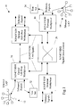
    Figure 1 shows an example of a data communications network 10 for transmitting data frames between two Ethernet LANs 12 and 14 via a transmission system 16 which uses SONET or SDH technology. Each Ethernet LAN has multiple stations or nodes (for example, workstations, file servers, print servers, printers and other appliances) connected in a star topology to one or more hubs or Ethernet switches. One of the hubs in each LAN 12 and 14 also has a connection to SONET or SDH access or aggregation equipment such as an optical add-drop multiplexer (OADM) 16 or a terminal multiplexer 18. This equipment receives tributary signals in their native formats (in the present case Ethernet frames) and either creates SONET/SDH frames by combining the tributary signals from multiple sources (terminal multiplexer) or inserts portions of a tributary signal into respective sections of the payload envelope of successive existing frames (add-drop multiplexer). The multiplexers 16 and 18 are interconnected over SONET/SDH links either directly or via digital crossconnect equipment 20. The details of SONET/SDH frame structure and of operation of equipment such as terminal multiplexers, add-drop multiplexers and cross-connects are well know to those skilled in the art and need not be discussed here.
    The installation and maintenance of a system such as the network 10 shown in Figure 1 frequently involves the transmission of test signals (Ethernet data frames) over selected paths in the network in order to confirm that the network equipment (links, multiplexers, cross-connects etc.) comprising those paths is operating correctly. For example, a test set 22 connected to the OADM 16 may be used to inject test frames into the network 10 for transmission to another test set 24 connected to the terminal multiplexer 18. However, testing of a system including Ethernet components is complicated by the need to specify one or more port addresses for each Ethernet component. The addressing scheme by which data frames are routed to their intended destination over an Ethernet LAN involves the allocation to each Ethernet interface equipment (plug-in card or integral circuitry) of a globally unique 12-digit (6-byte) hexadecimal station address such as 08:00:07:A9:B2:FC. Thus if a test engineer needs to transmit test data over the path from OADM 16 via the SONET/SDH network 10 to the terminal multiplexer 18, it has previously been necessary for the engineer to specify several such addresses for the test sets 22 and 24 at each end of the path. Given the format of these addresses this is a tedious task which is prone to error. Furthermore, there is no evident association of the addresses with connections between the test sets and the network, and no permanent association of the addresses with specific paths or equipment in the network. Accordingly interpreting the results of tests expressed in terms of Ethernet interface addresses has been difficult and time-consuming, and this significantly complicates and slows the process of analysing the results to determine the cause and location of a network fault.
    A predefined set of Ethernet station addresses are permanently stored and used selectively in both the test sets 22 and 24 to determine the destination addresses of Ethernet frames transmitted by the test sets. These station addresses are drawn from those allocated in accordance with Ethernet practice to the manufacturer of the test sets. Typically the set of addresses is the same for all examples of the same test set model, but different for different models. Selection of particular combinations of addresses in each test set is co-ordinated by the test sets in accordance with user selection of one of several predefined test modes, as described below. In addition, to maintain full flexibility of operation the user is able to configure all Ethernet addresses and related parameters individually, to cater for circumstances where the predefined test modes are not appropriate.
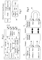
    Figure 2 shows, by way of example, the principal functionality of the test set 22 (and 24) for implementing the present invention. Referring to Figure 2, a set of Ethernet interface ports 26 (optical or electrical, 10Mb/s, 100Mb/s, 1Gb/s and/or 10Gb/s) is provided for connection to the network elements of the network 10 such as the OADM 16 and the terminal multiplexer 18. Four interface ports are shown, but a larger number may be provided if desired. Each Ethernet interface port comprises a transmit output Tx (e.g. containing a laser in the case of an optical port) and a receive input Rx (e.g. containing a photodiode receiver). The Ethernet ports 26 are coupled to a processor 28 which co-ordinates operation of the test set 22 in accordance with software program instructions stored in a memory 30. Test data to be transmitted via the Ethernet ports 26 are generated in a test data generator 32, for example using a pseudo-random binary sequence (PRBS) generator, and assembled with appropriate Ethernet MAC headers (described below) and check data to produce Ethernet frames. Likewise test data in Ethernet frames received via the Ethernet ports 26 are extracted by the processor 28 from the frames and supplied to a test data analyser 34 for validation. The functional requirements of the user of the test set and the results of tests performed are communicated via a user interface 36 (e.g. a display and input device such as a keyboard) controlled by the processor 28. The arrangement of functionality as shown in Figure 2 is illustrative only, and the details of practical implementation may vary. For example, most or all of the functionality of the test data analyser 34 may be provided by software algorithms stored in the memory 30 and executed by the processor 28.
    The Ethernet frames assembled by the test data generator 32 have a format shown in Figure 3, which in most respects conforms to the format of normal Ethernet frames. Each such frame starts with Media Access Control (MAC) information, such as a preamble, start-of-frame delimiter, destination address, source address and frame length/type indicator. The client data or payload comprises PRBS test data generated by the test data generator 32, followed by three fields of four bytes each of test set data 38. These three fields contain:
    • an identifier for the test data stream of which the frame is a part, comprising the physical port number (as distinct from station address) of the Ethernet port which transmitted the frame;
    • a sequence number for the frame within that stream; and
    • a cyclic redundancy check (CRC) code for the values within the test set data bytes 38. The client data are padded as necessary to the minimum specified length for an Ethernet frame, and followed by a frame check sequence (FCS) comprising a 32-bit CRC code.
    The test sets 22 and 24 provide four principal predefined test modes: Loopback (2-port), End-to-end, Loopback (1-port) and Loop-thru. Each test set stores the same overall set of Ethernet addresses which can be selectively allocated to different ones of the interface ports 26 in the test set and selectively included in Ethernet frames transmitted by different ports 26 in that or another test set. For the purposes of this description four of these addresses will be identified as Address A, Address B, Address X and Address Y.
    In many test configurations one (originating) test set will be generating and transmitting test data frames which will traverse the network under test to a remote test point. There they are either received and immediately validated in a second test set, or returned by a loop-back cable or a second test set to the originating set for validation. Each test set 22 and 24 can be configured as an originating set (Test Set 1) or a receiving/loop-back set (Test Set 2). When the Test Set 1 configuration is selected, Addresses A and B are associated with the test set's ports 1 and 2; when the Test Set 2 configuration is selected, Addresses X and Y are associated with those ports. The selection of addresses for inclusion as destination address in frames transmitted from each port for each of the predefined test modes is specified in the table below.
    Figure 00060001
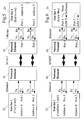
    Loopback 2-port) mode. In this mode, shown in Figure 4, only one test set 22 is used and loopback cables 40 connect Ethernet ports 1 and 2 on the remote network element (e.g. terminal multiplexer) 18, so that Ethernet frames received on either port are directed back immediately through the other port. The loopback cables 40 likewise interconnect other pairs of ports on the network element 18, such as port 3 with port 4, and port 5 with port 6. As can be seen from the table above, as a result of the selection of loopback (2-port) mode, the test set 22 transmits from its port 1 Ethernet frames containing Address B as the destination address; likewise it transmits from port 2 frames containing Address A as the destination address. Additional pairs of ports are mutually addressed in the same way, e.g. frames from port 3 contain the address of port 4 as destination, and frames from port 4 contain the address of port 3 as destination. This addressing together with the loopback cables 40 ensure that test frames transmitted by the test set 22 should be received back by it (although on another port), for validation and accumulation of test results.
    It can be seen that this test mode requires two Ethernet ports to be provided for testing at the network element 18, and the provision of two duplex links within the SONET/SDH network. In some cases it may also be necessary to invoke the use of Virtual Private Network (VPN) arrangements, to allow the system to accept Ethernet frames from the test set 22 for transport to the network element 18 even though there is no Ethernet receiving node with a relevant destination address coupled to that network element. These requirements can arise with certain Ethernet implementations, as a result of the inherent duplex nature of Ethernet systems, the presence of protocol layer 2 switching, the requirements of auto-negotiation and the use of Ethernet MAC addresses as described above. In some situations compliance with these requirements is undesirable or infeasible, such as where the network resources allocated to a particular path between test end points include only one SONET/SDH duplex link. To cater for these situations another test mode is provided as described below with reference to Loopback (1-port) and Loop-thru.
    End-to-end mode. In this mode, as shown in Figure 5, two test sets 22 and 24 are used, with the test set 22 configured as Test Set 1 and the test set 24 configured as Test Set 2. The test set 22 transmits from its port 1 Ethernet frames containing Address X of port 1 of the test set 24 as the destination address; likewise it transmits from port 2 frames containing Address Y of port 2 of the test set 24 as the destination address. Complementarily, frames transmitted from ports 1 and 2 of the test set 24 are addressed respectively to Addresses A and B of ports 1 and 2 of the test set 22. Thus the two test sets can exchange Ethernet frames over the network and check them for correct operation of the network.
    Loopback (1-port)/Loop-thru modes. These two modes are intended for use together, with a test set that is configured as Test Set 1 (the test set 22 in Figure 6) in Loopback (1-port) mode, and the test set that is configured as Test Set 2 (the test set 24) being in Loop-thru mode. The destination address for Ethernet frames sent from port 1 of the test set 22 is the same as in End-to-End mode, i.e. Address X of port 1 of the test set 24. However, the test set 24 is not arranged for independent generation of its own Ethernet frames. Instead it is arranged to retransmit on the same port the frames it receives, after having exchanged or swapped the source and destination addresses they contain and recalculated and updated each frame's FCS. Thus the frames it receives have Address A as source address and Address X as destination address, and it retransmits these frames with Address X as source address and Address A as destination address. Accordingly the test set 22 receives back on port 1 the frames it has transmitted from that port.
    With test sets configured in Loopback (1-port)/Loop-thru modes, a loopback test can be accomplished using just one port on each test set and with a single duplex link in the SONET/SDH network, irrespective of the specific implementation of Ethernet in use (e.g. with auto-negotiation). If desired, additional ports on the test sets 22 and 24 can be used to send additional test frames on a round trip through different paths across the network, for example between the ports 2 of the test sets as indicated in dashed line in Figure 6.
    In the implementation of the Loop-thru mode described above, the test set 24 retransmits all frames it receives. However, in the case where there is an Ethernet switch located in the network path to the test set 24 a problem can arise if that switch is reset or is in 'learn' mode (i.e. discovering the identity of other Ethernet devices to which it is connected). In these circumstances any frame received on any port of the switch will be transmitted on all the switch's other ports (so-called flooding) in an attempt to ensure that it will find its intended destination despite the absence of precise information in the switch about how to route the frame. In other words, there is an absence of the normal filtering which ensures that a port on the test set 24 receives only frames intended for it. Accordingly each port of the test set 24 receiving flooded frames from the switch will swap the source and destination addresses of all these flooded frames and return them to the switch. The switch will then see traffic on all ports with misleading apparent source addresses, which will confuse the switch's control software and prevent it from resolving its table of destination addresses versus ports.
    In order to avoid this problem, the test set 24 can be provided with two options for operation in Loop-thru mode:
  • Option 1: return with swapped addresses all frames received (as described above);
  • Option 2: return with swapped addresses only those frames addressed to the receiving port. In option 2 the test set 24 is arranged to return only those frames whose destination address matches the port address on which the frames are received. This avoids the potential flooding problem. If the switch floods all its output ports with a frame, only the test set's port with an address matching the address in the frame will return that frame, and the switch can continue to resolve its switching table.
  • Referring again to Figure 3 and as indicated above, the test set data 38 included in each Ethernet frame generated by the test sets 22 and 24 include an identification of the physical identity of the source Ethernet port which transmitted that frame. The tests sets 22 and 24 are arranged to look for this identifier in each received Ethernet frame, and extract it when it is found. The extracted identifier is used to control the display of test results on the user interface 36 (Figure 2), to provide a more meaningful indication of frame source than is possible with Ethernet addresses alone. Although it is known to extract and display Ethernet source addresses in test equipment, interpretation of this information is not easy. A user is typically required to consult a table associating Ethernet addresses to individual pieces of test equipment and specific Ethernet ports in them in order to make use of displayed source addresses. Given the length and format of such addresses, this is difficult, time-consuming and prone to misreading.
    In contrast, the test sets 22 and 24 can extract a more meaningful indication of equipment identity for display on the interface 36. For example, if End-to-End mode is in use, then the test set 22 is set to be Test Set 1. The processor 28 then configures the Ethernet ports 1 and 2 with the Addresses A and B respectively. Frames for transmission from those ports are constructed to have Addresses X and Y as destinations, as described above, and the identities of ports 1 and 2 are included in the data stream identifier of the test set bytes 38.
    When the frames are received by the test set 24, the data stream identifiers (port numbers) are extracted by the processor 28 and associated with the source addresses in the frames. This association enables the test set 24 to display the frame source information on its user interface 36 as "Far end port 1" or "Far end port 2" as appropriate. The "Far end" designation can be determined from the presence in the source address fields of the predefined addresses A and B which are known to both test sets although actively in use at the time only in the test set 22. References to the source of frames generated by the test set 24 (with source addresses X and Y) can likewise be displayed as "Near end port 1" or "Near end port 2".
    The presence of the data stream identifiers enables a meaningful indication of the frame source information to be provided even if the addressing of the Ethernet test frames has been changed, for example in accordance with a user's specific requirements.
    The example above has been described in the context of the use of Ethernet tributary streams, and the conventional terminology such as "data frame" and "station address" has accordingly been used. The invention may also be used in the context of other kinds of packet data networks, and the terminology used herein should therefore be understood to embrace also analogous concepts and features in such other kinds of networks for which alternative terminology is conventionally used (e.g. packets and network addresses instead of frames and station addresses).

    Claims (10)

    1. A tester for testing communication in a network which carries data frames between communications ports having respective addresses, comprising:
      a plurality of communications ports;
      a test data generator for generating test data frames to be transmitted via the communications ports;
      a store for storing a plurality of sets of predefined addresses to be associated with the communications ports; and
      a selector for receiving an indication of user selection of one of a plurality of test modes of the tester, and for selecting in accordance with that indication a respective one of the sets of predefined addresses for association with the communications ports.
    2. A tester according to claim 1, wherein the tester has a plurality of user-selectable operational configurations, and the sets of predefined addresses are also selected in an indication of user selection of an operational configuration.
    3. A tester according to claim 2, wherein the association of predefined addresses with the communications ports is as follows:
      Figure 00100001
    4. A tester for testing communication in a network which carries data frames between communications ports having respective addresses, each frame containing an indication of the addresses of the source and the intended destination of the frame, comprising:
      at least one communications port;
      a receiver for receiving a data frame arriving at the communications port;
      circuitry for exchanging the source and destination addresses contained in the received data frame; and
      a transmitter for transmitting the data frame with the exchanged addresses into the network.
    5. A tester according to claim 4, wherein the data frames transmitted with exchanged addresses are restricted to frames received with destination addresses matching an address of the communications port on which they were received.
    6. A tester for testing communication in a network which carries data frames between communications ports having respective addresses, comprising:
      a receiver for receiving test data frames transmitted through a network; and
      a source identifier for determining identity of a tester which transmitted the received test data frames and identity of a communications port via which the test data frames were transmitted.
    7. A tester according to claim 6, wherein the identity of the communications port via which the test data frames were transmitted is determined by reference to data additional to the respective address of the communications port.
    8. A tester according to claim 7, including:
      a plurality of communications ports; and
      a test data generator for generating test data frames to be transmitted via the communications ports, the test data generator being operative to include within each test data frame it generates an indication of the identity of the communications port from which the frame is to be transmitted, distinct from the address of that port.
    9. A tester for testing communication in a network which carries data frames between communications ports having respective addresses, comprising:
      a plurality of communications ports;
      a test data generator for generating test data frames to be transmitted via the communications ports;
      a store for storing a plurality of test modes of the tester; and
      a selector for receiving an indication of user selection of one of the test modes, and for selecting in accordance with that indication a respective mode of operation of the communications ports and of the test data generator.
    10. A tester according to claim 9, wherein the plurality of test modes includes at least two of:
      a mode in which test data frames are transmitted from a first communications port of the tester via the network to a second communications port of the tester;
      a mode in which test data frames are transmitted from a first communications port of the tester to a respective port of a second tester coupled to the network; and
      a mode in which test data frames are transmitted from a first communications port of the tester via the network and a second tester to the first communications port of the tester.
    EP02254839A 2002-05-30 2002-07-10 Testing network communications Withdrawn EP1367750A1 (en)

    Priority Applications (4)

    Application Number Priority Date Filing Date Title
    EP02254839A EP1367750A1 (en) 2002-05-30 2002-07-10 Testing network communications
    JP2003134807A JP2004032725A (en) 2002-05-30 2003-05-13 Test apparatus for network communication
    CN03123787A CN1462132A (en) 2002-05-30 2003-05-21 Testing network communication
    US10/448,540 US20030223376A1 (en) 2002-05-30 2003-05-29 Testing network communications

    Applications Claiming Priority (3)

    Application Number Priority Date Filing Date Title
    EP02253794A EP1367749A1 (en) 2002-05-30 2002-05-30 Apparatus for testing communications in a network which carries data frames
    EP02253794 2002-05-30
    EP02254839A EP1367750A1 (en) 2002-05-30 2002-07-10 Testing network communications

    Publications (1)

    Publication Number Publication Date
    EP1367750A1 true EP1367750A1 (en) 2003-12-03

    Family

    ID=29421906

    Family Applications (1)

    Application Number Title Priority Date Filing Date
    EP02254839A Withdrawn EP1367750A1 (en) 2002-05-30 2002-07-10 Testing network communications

    Country Status (4)

    Country Link
    US (1) US20030223376A1 (en)
    EP (1) EP1367750A1 (en)
    JP (1) JP2004032725A (en)
    CN (1) CN1462132A (en)

    Cited By (14)

    * Cited by examiner, † Cited by third party
    Publication number Priority date Publication date Assignee Title
    GB2400770B (en) * 2003-04-17 2006-03-22 Agilent Technologies Inc Testing network communications
    EP1814258A2 (en) * 2006-01-30 2007-08-01 Juniper Networks, Inc. Determining connectivity status for unnumbered interfaces of a target network device
    CN100396024C (en) * 2005-11-03 2008-06-18 华为技术有限公司 Testing device and testing method for exchanging network board
    US8339973B1 (en) 2010-09-07 2012-12-25 Juniper Networks, Inc. Multicast traceroute over MPLS/BGP IP multicast VPN
    US8472346B1 (en) 2007-06-08 2013-06-25 Juniper Networks, Inc. Failure detection for tunneled label-switched paths
    US8797886B1 (en) 2006-01-30 2014-08-05 Juniper Networks, Inc. Verification of network paths using two or more connectivity protocols
    US8902780B1 (en) 2012-09-26 2014-12-02 Juniper Networks, Inc. Forwarding detection for point-to-multipoint label switched paths
    US8953460B1 (en) 2012-12-31 2015-02-10 Juniper Networks, Inc. Network liveliness detection using session-external communications
    US9258234B1 (en) 2012-12-28 2016-02-09 Juniper Networks, Inc. Dynamically adjusting liveliness detection intervals for periodic network communications
    US9769017B1 (en) 2014-09-26 2017-09-19 Juniper Networks, Inc. Impending control plane disruption indication using forwarding plane liveliness detection protocols
    US10116544B2 (en) 2016-06-21 2018-10-30 Juniper Networks, Inc. Extended ping protocol for determining status for remote interfaces without requiring network reachability
    US10374936B2 (en) 2015-12-30 2019-08-06 Juniper Networks, Inc. Reducing false alarms when using network keep-alive messages
    US10397085B1 (en) 2016-06-30 2019-08-27 Juniper Networks, Inc. Offloading heartbeat responses message processing to a kernel of a network device
    US11750441B1 (en) 2018-09-07 2023-09-05 Juniper Networks, Inc. Propagating node failure errors to TCP sockets

    Families Citing this family (57)

    * Cited by examiner, † Cited by third party
    Publication number Priority date Publication date Assignee Title
    EP1533949B1 (en) * 2003-11-19 2006-12-27 Sony Deutschland GmbH Communication subsystem controlled information dissemination
    US20050259589A1 (en) * 2004-05-24 2005-11-24 Metrobility Optical Systems Inc. Logical services loopback
    US20050281392A1 (en) * 2004-06-18 2005-12-22 Covaro Networks, Inc. System and method for connection performance analysis
    CN100388692C (en) * 2004-06-22 2008-05-14 中兴通讯股份有限公司 Multi-mouth switching device and testing method for network exchanger
    US7408883B2 (en) * 2004-09-01 2008-08-05 Nettest, Inc. Apparatus and method for performing a loopback test in a communication system
    US7505418B1 (en) * 2004-11-01 2009-03-17 Empirix Inc. Network loopback using a virtual address
    US7239969B2 (en) 2004-11-09 2007-07-03 Guide Technology, Inc. System and method of generating test signals with injected data-dependent jitter (DDJ)
    WO2006063361A2 (en) 2004-12-08 2006-06-15 Guide Technology Periodic jitter (pj) measurement methodology
    CN100421392C (en) * 2004-12-15 2008-09-24 华为技术有限公司 System for realizing SDH logic test and its method
    CN100361460C (en) * 2005-03-14 2008-01-09 华为技术有限公司 On-line detector and method of communicator service
    US20060271670A1 (en) * 2005-05-31 2006-11-30 Blomquist Scott A System and method for partitioning network analysis
    CN100446480C (en) * 2005-08-05 2008-12-24 华为技术有限公司 Method for carrying out test on router
    US20070076632A1 (en) * 2005-10-05 2007-04-05 Hewlett-Packard Development Company, L.P. Network port for tracing a connection topology
    CN100517256C (en) * 2005-10-24 2009-07-22 鸿富锦精密工业(深圳)有限公司 IEEE1394 interface function detection device and method
    EP1885083A1 (en) 2006-08-03 2008-02-06 Acterna, LLC Triple play services tester
    US8004961B1 (en) * 2006-09-28 2011-08-23 National Semiconductor Corporation Independently configurable port redirection in a multi-port ethernet physical layer
    CN100592691C (en) * 2007-01-10 2010-02-24 中国电信股份有限公司 Automatic comparison method and system for the consistency test of the network management interface information model
    US8255188B2 (en) * 2007-11-07 2012-08-28 Guidetech, Inc. Fast low frequency jitter rejection methodology
    US8131927B2 (en) * 2007-11-30 2012-03-06 Hitachi, Ltd. Fast accessible compressed thin provisioning volume
    US7843771B2 (en) * 2007-12-14 2010-11-30 Guide Technology, Inc. High resolution time interpolator
    US7764621B1 (en) * 2007-12-28 2010-07-27 Ciena Corporation Packet loopback methods and replacing a destination address with a source address
    US8218540B1 (en) 2007-12-28 2012-07-10 World Wide Packets, Inc. Modifying a duplicated packet and forwarding encapsulated packets
    CN101299685B (en) * 2008-03-18 2010-12-15 华为技术有限公司 Method and system for testing switching network as well as test initiation module
    US8149730B1 (en) 2009-05-12 2012-04-03 Juniper Networks, Inc. Methods and apparatus related to packet generation and analysis
    US8174991B1 (en) * 2009-06-29 2012-05-08 Juniper Networks, Inc. Methods and apparatus related to analysis of test packets
    EP2341661B1 (en) * 2010-01-04 2012-03-21 Alcatel Lucent Neighbour discovery for ethernet private line on user network interfaces
    US8661292B2 (en) 2010-05-14 2014-02-25 Jds Uniphase Corporation Network communication at unaddressed network devices
    US8705395B2 (en) 2010-06-15 2014-04-22 Jds Uniphase Corporation Method for time aware inline remote mirroring
    US8798077B2 (en) 2010-12-29 2014-08-05 Juniper Networks, Inc. Methods and apparatus for standard protocol validation mechanisms deployed over a switch fabric system
    US8780896B2 (en) 2010-12-29 2014-07-15 Juniper Networks, Inc. Methods and apparatus for validation of equal cost multi path (ECMP) paths in a switch fabric system
    US8891385B2 (en) * 2011-01-04 2014-11-18 Alcatel Lucent Validating ethernet virtual connection service
    US9065723B2 (en) * 2011-04-04 2015-06-23 Jds Uniphase Corporation Unaddressed device communication from within an MPLS network
    US8861370B2 (en) * 2011-09-21 2014-10-14 Nxp B.V. System and method for testing a communications network having a central bus guardian (CBG) to detect a faulty condition associated with the CBG
    US9160644B1 (en) * 2011-11-09 2015-10-13 Marvell Israel (M.I.S.L) Ltd. Packet processor bandwidth verification methods and systems
    US9397895B2 (en) 2011-12-13 2016-07-19 Viavi Solutions Inc. Method and system for collecting topology information
    US9253062B2 (en) * 2011-12-23 2016-02-02 Ixia Byte by byte received data integrity check
    EP2629457A1 (en) 2012-02-15 2013-08-21 JDS Uniphase Corporation Method and System For Network Monitoring Using Signature Packets
    US9769078B2 (en) 2013-11-05 2017-09-19 Cisco Technology, Inc. Dynamic flowlet prioritization
    US9674086B2 (en) 2013-11-05 2017-06-06 Cisco Technology, Inc. Work conserving schedular based on ranking
    US9888405B2 (en) 2013-11-05 2018-02-06 Cisco Technology, Inc. Networking apparatuses and packet statistic determination methods employing atomic counters
    US9655232B2 (en) 2013-11-05 2017-05-16 Cisco Technology, Inc. Spanning tree protocol (STP) optimization techniques
    US10951522B2 (en) 2013-11-05 2021-03-16 Cisco Technology, Inc. IP-based forwarding of bridged and routed IP packets and unicast ARP
    US9825857B2 (en) 2013-11-05 2017-11-21 Cisco Technology, Inc. Method for increasing Layer-3 longest prefix match scale
    US9502111B2 (en) 2013-11-05 2016-11-22 Cisco Technology, Inc. Weighted equal cost multipath routing
    US10778584B2 (en) 2013-11-05 2020-09-15 Cisco Technology, Inc. System and method for multi-path load balancing in network fabrics
    US9374294B1 (en) 2013-11-05 2016-06-21 Cisco Technology, Inc. On-demand learning in overlay networks
    EP3066796B1 (en) 2013-11-05 2020-01-01 Cisco Technology, Inc. Network fabric overlay
    US9397946B1 (en) 2013-11-05 2016-07-19 Cisco Technology, Inc. Forwarding to clusters of service nodes
    US9876711B2 (en) 2013-11-05 2018-01-23 Cisco Technology, Inc. Source address translation in overlay networks
    US10313222B2 (en) 2015-07-13 2019-06-04 International Business Machines Corporation Diagnosis of a network adapter during network operation
    KR102262081B1 (en) * 2015-09-08 2021-06-07 현대자동차주식회사 Compliance test apparatus and method of communication node
    FR3060792B1 (en) * 2016-12-19 2018-12-07 Safran Electronics & Defense DATA LOADING DEVICE IN COMPUTERIZED DATA PROCESSING UNITS FROM A DATA SOURCE
    CN108199929A (en) * 2018-02-28 2018-06-22 上海市信息网络有限公司 Measuring instrument, network intelligence instrument system and network intelligence test method
    CN110687363A (en) * 2018-07-04 2020-01-14 佛山市顺德区顺达电脑厂有限公司 SFP port test fixture
    US10715410B2 (en) * 2018-07-18 2020-07-14 Google Llc Connectivity verification testing and topology discovery
    JP6969585B2 (en) * 2019-03-29 2021-11-24 オムロン株式会社 Master unit, arithmetic processing unit, programmable logic controller, network, and information processing method
    CN115913960A (en) * 2021-08-02 2023-04-04 北京车和家信息技术有限公司 Time-sensitive network verification equipment, method, device, system and medium

    Citations (7)

    * Cited by examiner, † Cited by third party
    Publication number Priority date Publication date Assignee Title
    EP0924901A2 (en) * 1997-12-22 1999-06-23 Nortel Networks Corporation Gigabit ethernet interface to synchronous network (Sonet) ring
    US6044400A (en) * 1995-03-25 2000-03-28 Lucent Technologies Inc. Switch monitoring system having a data collection device using filters in parallel orientation and filter counter for counting combination of filtered events
    US6098028A (en) * 1996-03-19 2000-08-01 Digital Lightwave, Inc. Communication line test apparatus with an improved graphical user interface
    EP1098491A2 (en) * 1999-11-08 2001-05-09 Agilent Technologies Inc. System and method for identifying related protocol data units
    EP1109360A1 (en) * 1999-12-17 2001-06-20 Nec Corporation ATM test equipment operable as source and responder for conducting multiple tests
    US6308218B1 (en) * 1997-09-17 2001-10-23 Sony Corporation Address look-up mechanism in a multi-port bridge for a local area network
    WO2001095561A2 (en) * 2000-06-05 2001-12-13 Exfo Protocol Inc. Hand-held electronic tester for telecommunications networks

    Family Cites Families (4)

    * Cited by examiner, † Cited by third party
    Publication number Priority date Publication date Assignee Title
    US5060226A (en) * 1990-07-05 1991-10-22 Phoenix Microsystems, Inc. Telecommunications network test system
    US5805571A (en) * 1996-03-19 1998-09-08 Zwan; Bryan J. Dynamic communication line analyzer apparatus and method
    US6816987B1 (en) * 2000-03-25 2004-11-09 Broadcom Corporation Apparatus and method for built-in self-test of a data communications system
    US6996758B1 (en) * 2001-11-16 2006-02-07 Xilinx, Inc. Apparatus for testing an interconnecting logic fabric

    Patent Citations (7)

    * Cited by examiner, † Cited by third party
    Publication number Priority date Publication date Assignee Title
    US6044400A (en) * 1995-03-25 2000-03-28 Lucent Technologies Inc. Switch monitoring system having a data collection device using filters in parallel orientation and filter counter for counting combination of filtered events
    US6098028A (en) * 1996-03-19 2000-08-01 Digital Lightwave, Inc. Communication line test apparatus with an improved graphical user interface
    US6308218B1 (en) * 1997-09-17 2001-10-23 Sony Corporation Address look-up mechanism in a multi-port bridge for a local area network
    EP0924901A2 (en) * 1997-12-22 1999-06-23 Nortel Networks Corporation Gigabit ethernet interface to synchronous network (Sonet) ring
    EP1098491A2 (en) * 1999-11-08 2001-05-09 Agilent Technologies Inc. System and method for identifying related protocol data units
    EP1109360A1 (en) * 1999-12-17 2001-06-20 Nec Corporation ATM test equipment operable as source and responder for conducting multiple tests
    WO2001095561A2 (en) * 2000-06-05 2001-12-13 Exfo Protocol Inc. Hand-held electronic tester for telecommunications networks

    Cited By (19)

    * Cited by examiner, † Cited by third party
    Publication number Priority date Publication date Assignee Title
    GB2400770B (en) * 2003-04-17 2006-03-22 Agilent Technologies Inc Testing network communications
    CN100396024C (en) * 2005-11-03 2008-06-18 华为技术有限公司 Testing device and testing method for exchanging network board
    EP1814258A2 (en) * 2006-01-30 2007-08-01 Juniper Networks, Inc. Determining connectivity status for unnumbered interfaces of a target network device
    EP1814258A3 (en) * 2006-01-30 2008-02-27 Juniper Networks, Inc. Determining connectivity status for unnumbered interfaces of a target network device
    US8117301B2 (en) 2006-01-30 2012-02-14 Juniper Networks, Inc. Determining connectivity status for unnumbered interfaces of a target network device
    US8797886B1 (en) 2006-01-30 2014-08-05 Juniper Networks, Inc. Verification of network paths using two or more connectivity protocols
    US8472346B1 (en) 2007-06-08 2013-06-25 Juniper Networks, Inc. Failure detection for tunneled label-switched paths
    US8339973B1 (en) 2010-09-07 2012-12-25 Juniper Networks, Inc. Multicast traceroute over MPLS/BGP IP multicast VPN
    US8902780B1 (en) 2012-09-26 2014-12-02 Juniper Networks, Inc. Forwarding detection for point-to-multipoint label switched paths
    US9258234B1 (en) 2012-12-28 2016-02-09 Juniper Networks, Inc. Dynamically adjusting liveliness detection intervals for periodic network communications
    US9781058B1 (en) 2012-12-28 2017-10-03 Juniper Networks, Inc. Dynamically adjusting liveliness detection intervals for periodic network communications
    US8953460B1 (en) 2012-12-31 2015-02-10 Juniper Networks, Inc. Network liveliness detection using session-external communications
    US9407526B1 (en) 2012-12-31 2016-08-02 Juniper Networks, Inc. Network liveliness detection using session-external communications
    US9769017B1 (en) 2014-09-26 2017-09-19 Juniper Networks, Inc. Impending control plane disruption indication using forwarding plane liveliness detection protocols
    US10374936B2 (en) 2015-12-30 2019-08-06 Juniper Networks, Inc. Reducing false alarms when using network keep-alive messages
    US10116544B2 (en) 2016-06-21 2018-10-30 Juniper Networks, Inc. Extended ping protocol for determining status for remote interfaces without requiring network reachability
    US10397085B1 (en) 2016-06-30 2019-08-27 Juniper Networks, Inc. Offloading heartbeat responses message processing to a kernel of a network device
    US10951506B1 (en) 2016-06-30 2021-03-16 Juniper Networks, Inc. Offloading heartbeat responses message processing to a kernel of a network device
    US11750441B1 (en) 2018-09-07 2023-09-05 Juniper Networks, Inc. Propagating node failure errors to TCP sockets

    Also Published As

    Publication number Publication date
    JP2004032725A (en) 2004-01-29
    CN1462132A (en) 2003-12-17
    US20030223376A1 (en) 2003-12-04

    Similar Documents

    Publication Publication Date Title
    EP1367750A1 (en) Testing network communications
    US20040208129A1 (en) Testing network communications
    US7043541B1 (en) Method and system for providing operations, administration, and maintenance capabilities in packet over optics networks
    US8200802B2 (en) Methods and systems for provisioning and maintaining a circuit in a data network
    US7548540B2 (en) Dynamic discovery of ISO layer-2 topology
    US6477566B1 (en) Method and system of providing improved network management data between a plurality of network elements and a management system for increasing a flow and decreasing an amount of data transfer
    US7433362B2 (en) System and method for SONET NSAP addressing
    US20040165534A1 (en) Operations, administration and maintenance (OAM) systems and methods for packet switched data networks
    US20050259589A1 (en) Logical services loopback
    KR101573195B1 (en) Network element for switching time division multiplex signals
    US7986619B2 (en) Packet network system
    US6891793B1 (en) Network system
    US8064347B2 (en) System and method for redundant switched communications
    US6404740B1 (en) System for testing internal connectivity in ATM switching equipment
    US7391734B2 (en) Method and system for obtaining logical performance data for a circuit in a data network
    US8169920B2 (en) Management interface and tool for benchmarking optical network topologies
    EP1367749A1 (en) Apparatus for testing communications in a network which carries data frames
    US7266110B1 (en) Apparatus and method for hybrid telecommunications switching
    CN114422420B (en) Route information processing method and network data management system
    EP2898630B1 (en) Network services testing with pluggable transceivers
    EP1921804B1 (en) Method and system for transmitting connectivity fault management messages in ethernet, and a node device
    EP1791308B1 (en) Method and system for communication using a partial Designated Transit List (DTL)
    CN112910682A (en) Link detection method and switch controller
    Kaplan et al. A transition architecture to SONET networks
    Chathnath Challenges in testing resilient packet ring

    Legal Events

    Date Code Title Description
    PUAI Public reference made under article 153(3) epc to a published international application that has entered the european phase

    Free format text: ORIGINAL CODE: 0009012

    AK Designated contracting states

    Kind code of ref document: A1

    Designated state(s): AT BE BG CH CY CZ DE DK EE ES FI FR GB GR IE IT LI LU MC NL PT SE SK TR

    AX Request for extension of the european patent

    Extension state: AL LT LV MK RO SI

    17P Request for examination filed

    Effective date: 20040603

    17Q First examination report despatched

    Effective date: 20040708

    AKX Designation fees paid

    Designated state(s): DE FR GB

    17Q First examination report despatched

    Effective date: 20040708

    RAP1 Party data changed (applicant data changed or rights of an application transferred)

    Owner name: AGILENT TECHNOLOGIES, INC.

    STAA Information on the status of an ep patent application or granted ep patent

    Free format text: STATUS: THE APPLICATION IS DEEMED TO BE WITHDRAWN

    18D Application deemed to be withdrawn

    Effective date: 20070124