EP1368233B1 - Carton, blank, methods and apparatus for making a carton - Google Patents
Carton, blank, methods and apparatus for making a carton Download PDFInfo
- Publication number
- EP1368233B1 EP1368233B1 EP02704183.9A EP02704183A EP1368233B1 EP 1368233 B1 EP1368233 B1 EP 1368233B1 EP 02704183 A EP02704183 A EP 02704183A EP 1368233 B1 EP1368233 B1 EP 1368233B1
- Authority
- EP
- European Patent Office
- Prior art keywords
- panel
- edges
- edge
- fold
- substantially parallel
- Prior art date
- Legal status (The legal status is an assumption and is not a legal conclusion. Google has not performed a legal analysis and makes no representation as to the accuracy of the status listed.)
- Expired - Lifetime
Links
Images


Classifications
-
- B—PERFORMING OPERATIONS; TRANSPORTING
- B65—CONVEYING; PACKING; STORING; HANDLING THIN OR FILAMENTARY MATERIAL
- B65B—MACHINES, APPARATUS OR DEVICES FOR, OR METHODS OF, PACKAGING ARTICLES OR MATERIALS; UNPACKING
- B65B7/00—Closing containers or receptacles after filling
- B65B7/16—Closing semi-rigid or rigid containers or receptacles not deformed by, or not taking-up shape of, contents, e.g. boxes or cartons
- B65B7/20—Closing semi-rigid or rigid containers or receptacles not deformed by, or not taking-up shape of, contents, e.g. boxes or cartons by folding-down preformed flaps
-
- B—PERFORMING OPERATIONS; TRANSPORTING
- B65—CONVEYING; PACKING; STORING; HANDLING THIN OR FILAMENTARY MATERIAL
- B65D—CONTAINERS FOR STORAGE OR TRANSPORT OF ARTICLES OR MATERIALS, e.g. BAGS, BARRELS, BOTTLES, BOXES, CANS, CARTONS, CRATES, DRUMS, JARS, TANKS, HOPPERS, FORWARDING CONTAINERS; ACCESSORIES, CLOSURES, OR FITTINGS THEREFOR; PACKAGING ELEMENTS; PACKAGES
- B65D5/00—Rigid or semi-rigid containers of polygonal cross-section, e.g. boxes, cartons or trays, formed by folding or erecting one or more blanks made of paper
- B65D5/02—Rigid or semi-rigid containers of polygonal cross-section, e.g. boxes, cartons or trays, formed by folding or erecting one or more blanks made of paper by folding or erecting a single blank to form a tubular body with or without subsequent folding operations, or the addition of separate elements, to close the ends of the body
- B65D5/06—Rigid or semi-rigid containers of polygonal cross-section, e.g. boxes, cartons or trays, formed by folding or erecting one or more blanks made of paper by folding or erecting a single blank to form a tubular body with or without subsequent folding operations, or the addition of separate elements, to close the ends of the body with end-closing or contents-supporting elements formed by folding inwardly a wall extending from, and continuously around, an end of the tubular body
- B65D5/061—Rectangular containers having a body with gusset-flaps folded inwardly beneath the closure flaps
-
- B—PERFORMING OPERATIONS; TRANSPORTING
- B65—CONVEYING; PACKING; STORING; HANDLING THIN OR FILAMENTARY MATERIAL
- B65D—CONTAINERS FOR STORAGE OR TRANSPORT OF ARTICLES OR MATERIALS, e.g. BAGS, BARRELS, BOTTLES, BOXES, CANS, CARTONS, CRATES, DRUMS, JARS, TANKS, HOPPERS, FORWARDING CONTAINERS; ACCESSORIES, CLOSURES, OR FITTINGS THEREFOR; PACKAGING ELEMENTS; PACKAGES
- B65D5/00—Rigid or semi-rigid containers of polygonal cross-section, e.g. boxes, cartons or trays, formed by folding or erecting one or more blanks made of paper
- B65D5/42—Details of containers or of foldable or erectable container blanks
- B65D5/4266—Folding lines, score lines, crease lines
-
- Y—GENERAL TAGGING OF NEW TECHNOLOGICAL DEVELOPMENTS; GENERAL TAGGING OF CROSS-SECTIONAL TECHNOLOGIES SPANNING OVER SEVERAL SECTIONS OF THE IPC; TECHNICAL SUBJECTS COVERED BY FORMER USPC CROSS-REFERENCE ART COLLECTIONS [XRACs] AND DIGESTS
- Y10—TECHNICAL SUBJECTS COVERED BY FORMER USPC
- Y10S—TECHNICAL SUBJECTS COVERED BY FORMER USPC CROSS-REFERENCE ART COLLECTIONS [XRACs] AND DIGESTS
- Y10S229/00—Envelopes, wrappers, and paperboard boxes
- Y10S229/93—Fold detail
- Y10S229/931—Fold includes slit or aperture
Description
- The present disclosure pertains to a carton, a blank for producing a carton, and methods and apparatuses for erecting, closing and sealing a carton. More particularly, the present invention pertains to a carton which can be rapidly and automatically erected and, after filling, automatically and rapidly closed and sealed. The present disclosure further pertains to methods and apparatuses for erecting, closing, and sealing cartons of different sizes without adjustment of the apparatuses to accommodate the different sizes. The present invention is particularly suited for corrugated cartons.
- Numerous businesses need to ship large quantities of goods and utilize cartons, particularly corrugated cartons, to hold the goods during shipment. Consequently, such businesses desire to be able to rapidly erect, fill, close, and seal their shipping cartons.
Figure 1 illustrates a typicalprior art carton 10 havingside surfaces 12 andend surfaces 14.Carton 10 also includes a bottom surface (not shown).Closure panels 16 extend upwardly fromside surfaces 12, whileclosure panels 18 extend upwardly fromend surfaces 14.Figure 2 depicts a carton blank 20 from which acarton 10 might be erected. Carton blank 20 includes the panels 12-18 shown inFigure 1 and alsobottom panels top panels sealing strip 26 which extends from one panel, such as theoutermost end panel 14 as illustrated inFigure 2 , so that when the carton is erected,strip 26 can be sealed to theadjacent side panel 12, as illustrated inFigure 1 . To enable the necessary folds,panels slots 19, and likewisepanels slots 25. Consequently, it is time consuming and expensive to form blank 20. - Erecting
carton 10 from blank 20 requiresfolding panels panels bottom panels 22, and sealing thesealing strip 26 to the adjacent panel. The several folds must be performed in sequence, and so require significant time. - Once
carton 10 is filled with goods,panels 18 are folded inwardly to overlie those goods, and thenpanels 16 are folded overpanels 18 and the goods to close the carton. The carton then might be sealed, for example by applying a tape along the junction of the twopanels 16.Figure 3 depicts the resulting closedcarton 10. The fourseparate closure panels panels 18 folded beforepanels 16. Consequently, a significant time is required to closecarton 10. The junction of the twotop panels 16 must then be sealed. - While these various operations might be mechanized, still the large number of steps results in the operations being time consuming. In addition, different sizes of cartons require different equipment sizes in order to perform the operations mechanically. This requires either different apparatuses for different carton sizes, or an apparatus which is adjustable in size, then necessitating the adjustment of the size each time the carton size changes. In addition to being time consuming, these approaches are expensive.
-
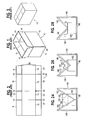
Figure 9 depicts acarton 162 havingside panels end panels top panels side panels panels end panels Panels end panels fold lines panel fold lines 152 which extend from a point substantially at the center of the panel upper edgeopposite fold line panel fold line panel panels fold lines fold line 152 and causingtop panels carton 162, as depicted inFigures 10 and 11 . Continued such pressure will bringcarton 162 to its closed condition, depicted inFigure 12 . - The necessity to make a 180° fold in each
fold line 152 has limited the applicability of this type of carton. By way of example, United States Patent No.2,439,435 shows such a carton used for moisture-proof packaging. However, to permit the 180° folds that are necessary, the carton of this patent is made of paper board. United States Patent No.5,143,281 shows such a carton made of cardboard having a foil to provide a liquid-tight package. United States Patent No.5,078,315 likewise shows a liquid containing package having 180° folds. This package is formed of a laminate of paper, thermal plastic, and possibly aluminum foil. United States Patent No.2,810,506 shows a carton with 180° folds which is made of a sheet material. United States Patent No.5,056,707 similarly shows a carton made of a sheet material coated with thermoplastics to permit containing of liquids. All of thin material can readily be folded 180°. However, cartons made of such thin materials are unsuitable for heavy duty cartons used for shipping. - United States Patent No.
915,579 shows a shipping container made of a corrugated material and utilizing 180° folds on end flaps. However, the end flaps are first crushed to permit such folding. This, of course, destroys the corrugations and weakens the materials. United States Patent No.2,926,777 US5692672 upon which the preamble of claim 1 is based andUS3302849 upon which the preamble ofclaim 6 is based. - In one aspect, the present invention is a corrugated carton including top panels joined by fold-in panels that fold 180° on fold lines uniquely designed to facilitate that folding. In a second aspect, the present invention is a blank for producing such a corrugated carton. Further aspects of the present invention are methods of and apparatuses for erecting, closing, and sealing a corrugated carton. The carton blank has 180° fold lines that include compressed area at each end and a slit joining the compressed areas. The apparatus for erecting the carton includes a vacuum source for holding the carton stationary as it is erected. The carton closing apparatus includes a V-shaped member that closes the carton top regardless of the carton size. The apparatus for sealing the carton has a second V-shaped member and a sealing arm that is pivotally suspended to bring a sealing wheel into contact with the carton. The carton can be erected, closed, and sealed by hand, if desired, and such manual operations are more readily done with the carton of the present invention than with the prior art carton of
Figure 1 . All the panels that close the carton can be folded into place at the same time by simply pressing on any one of the panels. - These and other aspects and advantages of the present invention are more apparent from the following detailed description and claims, particularly when considered in conjunction with the accompanying drawings in which like parts bear like reference numerals: In the drawings:
-
Figure 1 depicts an open prior art carton; -
Figure 2 depicts a carton blank from which the carton ofFigure 1 can be erected; -
Figure 3 depicts the carton ofFigure 1 closed; -
Figure 4 depicts a first preferred embodiment of a carton blank in accordance with the present invention; -
Figure 5 is an enlarged fragmentary view of area 5-5 ofFigure 4 ; -
Figure 6 is a sectional view taken on line 6-6 ofFigure 5 ; -
Figure 7 is a sectional view taken on line 7-7 ofFigure 5 ; -
Figure 8 is a fragmentary view of a 180° fold as made in a carton blank in accordance with the present invention; -
Figures 9-13 depict a carton in accordance with the present invention in various degrees of closing; -
Figures 14-21 illustrate preferred embodiments of a method of and an apparatus for erecting a carton in accordance with the present invention; -
Figure 22 depicts a second preferred embodiment of a carton blank in accordance with the present invention; -
Figures 23-28 illustrate preferred embodiments of methods and apparatuses for closing and sealing a carton in accordance with the present invention; and -
Figure 29 depicts an alternative embodiment of a carton in accordance with the present invention. -
Figure 4 depicts a preferred embodiment of a carton blank 30 from which a carton in accordance with the present invention can be erected.Blank 30 includes afirst side panel 32 having afirst end edge 34, asecond end edge 36, atop edge 38 and abottom edge 40. End edges 34 and 36 are substantially parallel with each other, whiletop edge 38 andbottom edge 40 are substantially parallel with each other and substantially perpendicular toedges Blank 30 further includes afirst end panel 42 having afirst side edge 44, asecond side edge 46, atop edge 48, and abottom edge 50. Carton blank 30 also includes asecond side panel 52 having afirst end edge 54, a second end edge 56, atop edge 58, and abottom edge 60.Carton 30 further includes asecond end panel 62 having afirst side edge 64, asecond side edge 66, a top edge 68, and abottom edge 70.Edges edge 34, whileedges edge 38, and edges 50, 60, and 70 are extensions ofedge 40. - Carton blank 30 also includes a first
top panel 72 having afirst side edge 74, a second side edge 76, a first end edge 78, and a second end edge 80.Edges 74 and 76 are substantially parallel withedge 38, and edges 78 and 80 are extensions ofedges bottom panel 82 having afirst side edge 84, asecond side edge 86, afirst end edge 88, and asecond end edge 90.Edges edge 38, whileedges edges panel 92 having afirst end edge 94, a second end edge 96, a first side edge 98, and a second side edge 100.Edges 94 and 96 are extensions ofedges 74 and 76, respectively, while edges 98 and 100 are extensions ofedges panel 102 having afirst end edge 104, a second end edge 106, afirst side edge 108, and asecond side edge 110.Edges 104 and 106 are extensions ofedges edges edges top panel 112 having afirst side edge 114, a second side edge 116, afirst end edge 118, and asecond end edge 120.Edges 114 and 116 are extensions ofedges 94 and 96, respectively, whileedges edges 54 and 56, respectively. Carton blank 30 includes a second bottom panel 122 having afirst side edge 124, asecond side edge 126, a first end edge 128, and a second end edge 130.Edges edges 104 and 106, respectively, while edges 128 and 130 are extensions ofedges 54 and 56, respectively. Carton blank additionally includes a third fold-inpanel 132 having afirst end edge 134, asecond end edge 136, afirst side edge 138, and asecond side edge 140.Edges edges 114 and 116, respectively, whileedges edges panel 142 having afirst end edge 144, asecond end edge 146, afirst side edge 148 and asecond side edge 150.Edges edges edges edges -
First end panel 42 extends fromfirst side panel 32, withfirst side edge 44 offirst end panel 42 joined tosecond side edge 36 offirst side panel 32 to define a 90° fold line.Second side panel 52 extends fromfirst end panel 42, withfirst end edge 54 joined tosecond side edge 46 to define a 180° fold line.Second end panel 62 extends fromsecond side panel 52, withfirst side edge 64 joined to second end edge 56 to define a 90° fold line. Firsttop panel 72 extends fromfirst side panel 32, withfirst side edge 74 joined totop edge 38 to define a 90° fold line. Firstbottom panel 82 extends fromfirst side panel 32, withfirst side edge 84 joined tobottom edge 40 to define a 90° fold line. First fold-inpanel 92 extends fromfirst end panel 42, withfirst end edge 94 joined totop edge 48 to define a 90° fold line and with first side edge 98 joined to second end edge 80 to define a 180° fold line. Second fold-inpanel 102 extends fromfirst end panel 42, withfirst end edge 104 joined tobottom edge 50 to define a 90° fold line and withfirst side edge 108 joined tosecond end edge 90 to define a 180° fold line. Secondtop panel 112 extends fromsecond side panel 52, withfirst side edge 114 joined totop edge 58 to define a 90° fold line and withfirst end edge 118 joined to second side edge 100 of first fold-inpanel 92 to define a 180° fold line. Second bottom panel 122 extends fromsecond side panel 52, withfirst side edge 124 joined tobottom edge 60 to define a 90° fold line and with first end edge 128 joined tosecond side edge 110 of second fold-inpanel 102 to define a 180° fold line. Third fold-inpanel 132 extends fromsecond end panel 62, withfirst end edge 134 joined to top edge 68 to define a 90° fold line and withfirst side edge 138 joined tosecond end edge 120 oftop panel 112 to define a 180° fold line. Fourth fold-inpanel 142 extends fromsecond end panel 62, withfirst end edge 144 joined tobottom edge 70 to define a 90° fold line and withfirst side edge 148 joined to second end edge 130 of bottom panel 122 to define a 180° fold line. - Each fold-in
panel fold lines 152 which extend from a point on thesecond end edge first end edge - Preferably, carton blank 30 also includes a
sealing strip 154, for example extending from third fold-inpanel 132,second end panel 62, and fourth fold-inpanel 142 as depicted inFigure 4 .Sealing strip 154 includes fold lines which are extensions of the 90° fold lines defined byedges 68 and 134 andedges edges strip 154 is sealed topanels Figure 15 . Alternatively, sealingstrip 154 can be omitted, andpanels panels Figure 22 . -
Figures 5-8 show the form of the 180° fold lines. Each 180° fold line includes first and secondcompressed areas 156 which extend from opposite ends of the 180° fold line for a distance in the order of about two inches and which are joined by aslit 158. Eachcompressed area 156 is preferably oval in shape with a maximum width in the order of from about ⅜ inch to about ½ inch for standard packing carton corrugated panels. As can be seen inFigure 6 , eachcompressed area 156 extends into the material of carton blank 30 a substantial distance, while leaving the adjacent panel portions joined. Preferably, aprotrusion 160 extends from the undersurface of carton blank 30, substantially along the center line of eachcompressed area 156 to define a fold line. As can be seen inFigure 7 , each slit 158 extends throughcarton blank 30. -
Figure 8 illustrate the manner in which carton blank 30 can be folded 180° as a result of the 180° fold lines formed bycompressed areas 156 and slits 158. As can be seen inFigure 8 , as a result ofcompressed areas 156, the 180° fold is readily made without unduly stressing the carton blank material. -
Figures 9-13 illustrate the manner in which acarton 162 formed from carton blank 30 can be closed after the carton has been erected and filled. InFigure 9 ,carton 162 is illustrated withtop panels panels Figure 10 illustratescarton 162 when fold-inpanels Top panels Figure 11 depictscarton 162 with the fold-inpanels 152 further folded in and withtop panels Figure 12 illustratescarton 162 full closed.Figure 13 shows theclosed carton 162 withtop panels tape 164.Carton 162 can be closed and sealed with the method and apparatus of the present invention. Alternatively, if desired,carton 162 can be closed and sealed, as well as erected, manually. Manual erecting and closing ofcarton 162 can be done rapidly by simply pressing on any one of the bottom panels to erect the carton and any one of the top panels to close the carton. Pressing on any one of the bottom panels or of the top panels causes all of the bottom panels or the top panels to fold inwardly, closing the bottom or the top. -
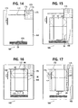
Figures 14-21 illustrate anapparatus 166 for erectingcarton 162 fromcarton blank 30.Apparatus 166 includes an erectingsurface 168. A number ofcarton blanks 30 are provided adjacent one end of erectingsurface 168, preferably standing on edge as illustrated inFigure 14 . When acarton 162 is to be erected, one of thecarton blanks 30 is released from the stack and falls onto erectingsurface 168 as depicted inFigure 15 . Carton blank 30 is then supported on erectingsurface 168 withend panel 62 overlying a portion ofside panel 32, with third and fourth fold-inpanels top panel 72 and firstbottom panel 82 respectively, and with sealingstrip 154 sealed toside panel 32,top panel 72 andbottom panel 82. If desired, rather than the singlepiece carton blank 30 ofFigure 4 , the carton blank could be formed of twoblanks 169 as illustrated inFigure 22 . The twoblanks 169 are then positioned one over the other, with one rotated 180° with respect to the other, and the sealing strip of each blank is sealed to the other blank. This construction provides a carton blank 30 just as illustrated inFigure 15 . - A
first actuator 170 is provided adjacent one end of erectingsurface 168, and asecond actuator 174 is provided adjacent one side of the erecting surface, as depicted inFigure 14 . Avacuum belt 175 having a number ofopenings 176 defines an erecting position adjacent the corner of erectingsurface 168 remote fromactuators Openings 176 are connected to a vacuum source (not shown). As illustrated inFigure 16 ,first actuator 170 advances the carton blank 30 until the joined edges 34 and 66 abut against astop member 172 adjacent the end of erectingsurface 168opposite actuator 170.Second actuator 174 then advances the blank 30 in a direction perpendicular to that ofactuator 170 so that one corner of blank 170 overlies theopenings 176 at a portion ofvacuum belt 175, as depicts inFigure 17 . Suction is then applied throughopenings 174, firmly holding inplace bottom panel 82, which is beneath fourth fold-inpanel 142.First actuator 170 advances further, causing the carton blank to fold 90° on the fold lines defined by the respective joined edges 36-42, 80-98, 90-108, 46-54, 100-118, 110-128, 56-64, 120-138, and 130-148, bringing the partially erected carton to the position depicted inFigure 18 . As illustrated inFigure 19 ,second actuator 174 then advances the carton blank in its direction of travel while suction is continued throughopenings 176, causing the carton blank to fold 90° on the fold lines defined by the respective joined edges 38-74, 40-84, 48-94, 50-104, 58-114, 60-124, 68-134, and 70-144. This erects thecarton 162 and positions it over several of theopenings 176 ofvacuum belt 175, as depicted inFigure 19. Figure 20 illustratesvacuum belt 175 movingcarton 162 over a sealingunit 178, for example a tape sealing unit, which sealsbottom panels 82 and 122 together, completing the erection ofcarton 162.Figure 21 then depicts the erectedcarton 162 being conveyed for filling while asecond carton blank 30 is released onto erectingsurface 168. -
Figures 23-28 illustrate the closing of the filledcarton 162. Filled cartons are conveyed by afirst conveyor 180 to aconveyor 182 ofcarton closing apparatus 184. A pair of upwardly extendingframe member 186 pivotally support a V-shaped centeringmember 188 aboveconveyor 182. As seen inFigure 24 , centeringmember 188 includes a pair ofarms 190 which have their upper ends pivotally mounted to the upper ends offrame members 186. The lower ends ofarms 190 are connected together at a point above substantially the center ofconveyor 182. As the filledcontainer 162 progresses onconveyor 182, it enters the central opening betweenarms 190 of centeringmember 188. Ascontainer 162 progresses further,arms 190 contact thetop panels carton 162. The initial contact assures thatcarton 162 is substantially centered onconveyor 182. Further movement ofcontainer 162 onconveyor 182 bringscarton 162 into a more narrow portion of the central opening of centeringmember 188, as depicted inFigure 25 . This causesarms 190 to forcetop panels panels Figures 10, 11 and26 . Continued movement ofcarton 162 onconveyor 182 results in full closing oftop panel Figures 27 and28 , providing the closed carton ofFigure 12 . - The V-shaped form of centering
member 188 allowscarton closing apparatus 184 to be used with cartons of various sizes. Regardless of the height or width of the carton, itstop panels arms 190 and be closed as the carton progresses onconveyor 182. - Once the
carton 162 is fully closed, as depicted inFigure 27 , the carton can be sealed by sealingapparatus 192. As depicted inFigure 23 , sealingapparatus 192 includes aconveyor 194 to which the closed cartons are transferred fromconveyor 182.Figure 23 depicts aclosed carton 162a onconveyor 194.Closing apparatus 192 includes a pair offrame members 196 which pivotally support a centeringmember 198, similar to centeringmember 188. Again, centeringmember 198 assures thatcarton 162a is substantially centered onconveyor 194.Support members 196 further pivotallysupport sealing arm 200 above the central opening of centeringmember 198.Sealing arm 200 rotatably supports areel 202 of tape or other suitable sealing material.Sealing arm 200 terminates in afirst sealing roller 204 and pivotally supports anarm 206 which supports asecond sealing roller 208.Tape 210 fromreel 202 wraps aroundrollers leading end panel 62 ofcarton 162a, as depicted inFigure 23 . Ascarton 162a progresses onconveyor 194, sealingarm 200 pivots upwardly, bringing sealingrollers closed carton 162. This applies tape along the junction oftop panels carton 162a, as illustrated inFigure 25 . Further movement ofcarton 162a onconveyor 194 results inrollers second end panel 42 ofcarton 162a, as depicted inFigure 27 . The sealing mechanism can include a blade or other suitable means which is actuated by movement of thearm 206 to the position ofFigure 27 to cut the tape oncecarton 162a is fully sealed. -
Figure 29 depicts an alternative embodiment ofcarton 162b having astrip 212 of sealing tape afixed totop panel 112 so that whentop panels panel 72, sealing the carton. With this embodiment, sealingapparatus 192 is not necessary. - The present invention is thus seen to provide an improved carton blank that can be readily erected closed, and sealed.
Claims (10)
- A blank for producing a carton, said blank comprising:a first side panel having substantially parallel first and second end edges and substantially parallel top and bottom edges extending substantially perpendicular to the end edges;a first end panel having first and second side edges substantially parallel with the first side panel end edges, and having substantially parallel top and bottom edges, said first end panel extending from said first side panel with the first end panel first side edge joined to the first side panel second end edge to define a first 90° fold line and with the first end panel top and bottom edges being extensions of the first side panel top and bottom edges respectively;a second side panel having first and second end edges substantially parallel with the first side panel end edges, and having substantially parallel top and bottom edges, said second side panel extending from said first end panel with the second side panel first end edge joined to the first end panel second side edge to define a first 180° fold line parallel with the first 90° fold line and with the second side panel top and bottom edges being extensions of the first end panel top and bottom edges respectively;a second end panel having first and second side edges substantially parallel with the first side panel end edges, and having substantially parallel top and bottom edges, said second end panel extending from said second side panel with the second end panel first side edge joined to the second side panel second end edge to define a second 90° fold line and with the second end panel top and bottom edges being extensions of the second side panel top and bottom edges respectively;a first top panel having first and second side edges substantially parallel with the first side panel top edge, and having substantially parallel first and second end edges, said first top panel extending from said first side panel with the first top panel first side edge joined to the first side panel top edge to define a third 90° fold line and with the first top panel first and second end edges being extensions of the first side panel first and second end edges respectively;a first bottom panel having first and second side edges substantially parallel with the first side panel bottom edge, and having substantially parallel first and second end edges, said first bottom panel extending from said first side panel with the first bottom panel first side edge joined to the first side panel bottom edge to define a fourth 90° fold line and with the first bottom panel first and second end edges being extensions of the first side panel first and second end edges respectively;a first fold-in panel having first and second end edges substantially parallel with the first end panel top edge, and having substantially parallel first and second side edges, said first fold-in panel extending from said first end panel with the first fold-in panel first end edge joined to the first end panel top edge to define a fifth 90° fold line, with the first fold-in panel side edges being extensions of the first end panel first and second side edges respectively, and with the first fold-in panel first side edge joined to the first top panel second end edge to define a second 180° fold line;a second fold-in panel having first and second end edges substantially parallel with the first end panel bottom edge, and having substantially parallel first and second side edges, said second fold-in panel extending from said first end panel with the second fold-in panel first end edge joined to the first end panel bottom edge to define a sixth 90° fold line, with the second fold-in panel first and second side edges being extensions of the first end panel first and second side edges respectively, and with the second fold-in panel first side edge joined to the first bottom panel second end edge to define a third 180° fold line;a second top panel having first and second side edges substantially parallel with the second side panel top edge, and having substantially parallel first and second end edges, said second top panel extending from said second side panel with the second top panel first side edge joined to the second side panel top edge to define a seventh 90° fold line, with the second top panel first and second end edges being extensions of the second side panel first and second end edges respectively, and with the second top panel first end edge joined to the first fold-in panel second side edge to define a fourth 180° fold line;a second bottom panel having first and second side edges substantially parallel with the second side panel bottom edge, and having substantially parallel first and second end edges, said second bottom panel extending from said second side panel with the second bottom panel first side edge joined to the second side panel bottom edge to define an eighth 90° fold line, with the second bottom panel first and second end edges being extensions of the second side panel first and second end edges respectively, and with the second bottom panel first end edge joined to the second fold-in panel second side edge to define a fifth 180° fold line;a third fold-in panel having first and second end edges substantially parallel with the second end panel top edge, and having substantially parallel first and second side edges, said third fold-in panel extending from said second end panel with the third fold-in panel first end edge joined to the second end panel top edge to define a ninth 90° fold line, with the third fold-in panel first and second side edges being extensions of the second end panel first and second side edges respectively, and with the third fold-in panel first side edge joined to the second top panel second end edge to define a sixth 180° fold line; anda fourth fold-in panel having first and second end edges substantially parallel with the second end panel bottom edge, and having substantially parallel first and second side edges, said fourth fold-in panel extending from said second end panel with the fourth fold-in panel first end edge joined to the second end panel bottom edge to define a tenth 90° fold line, with the fourth fold-in panel first and second side edges being extensions of the second bottom panel first and second side edges respectively, and with the fourth fold-in panel first side edge joined to the second bottom panel second end edge to define a seventh 180° fold line;each fold-in panel having 180° fold lines extending from a point on the second end edge of such panel substantially midway between the first and second side edges thereof to points at the intersections of the first end edge thereof and the first and second side edges thereof, characterised in that the blank is corrugated andeach 180° fold line comprises a first compressed area extending from a first end of the 180° fold line, a second compressed area extending from a second end of the 180° fold line, and a slit joining the first and second compressed areas.
- A blank as claimed in claim 1, further comprising a sealing strip for sealing the blank as a carton.
- A blank as claimed in claim 1, wherein each compressed area provides a protrusion extending from the surface of the blank opposite the compressed area to define the fold line.
- A blank as claimed in claim 1, wherein each compressed area is oval in shape.
- A carton erected from the blank of claim 1.
- A blank for producing a carton when joined with a like blank, said blank comprising:a side panel having substantially parallel first and second end edges and substantially parallel top and bottom edges extending substantially perpendicular to the end edges;an end panel having first and second side edges substantially parallel with the side panel end edges, and having substantially parallel top and bottom edges, said end panel extending from said side panel with the end panel first side edge joined to the side panel second end edge to define a first 90° fold line and with the end panel top and bottom edges being extensions of the side panel top and bottom edges respectively;a top panel having first and second side edges substantially parallel with the side panel top edge, and having substantially parallel first and second end edges, said top panel extending from said side panel with the top panel first side edge joined to the side panel top edge to define a second 90° fold line and with the top panel first and second end edges being extensions of the side panel first and second end edges respectively;a bottom panel having first and second side edges substantially parallel with the side panel bottom edge, and having substantially parallel first and second end edges, said bottom panel extending from said side panel with the bottom panel first side edge joined to the side panel bottom edge to define a third 90° fold line and with the bottom panel first and second end edges being extensions of the side panel first and second end edges respectively;a first fold-in panel having first and second end edges substantially parallel with the end panel top edge, and having substantially parallel first and second side edges, said first fold-in panel extending from said end panel with the first fold-in panel first end edge joined to the end panel top edge to define a fourth 90° fold line, with the first fold-in panel first and second side edges being extensions of the end panel first and second side edges respectively, and with the first fold-in panel first side edge joined to the top panel second end edge to define a first 180° fold line;a second fold-in panel having first and second end edges substantially parallel with the end panel bottom edge and substantially parallel first and second side edges, said second fold-in panel extending from said end panel with the second fold-in panel first end edge joined to the end panel bottom edge to define a fifth 90° fold line, with the second fold-in panel first and second side edges being extensions of the end panel first and second side edges respectively, and with the second fold-in panel first side edge joined to the bottom panel second end edge to define a second 180° fold line;each fold-in panel having 180° fold lines extending from a point on the second end edge of such panel substantially midway between the first and second side edges thereof to points at the intersections of the first end edge thereof and the first and second side edges thereof, characterised in that the blank is corrugated andeach 180° fold line comprises a first compressed area extending from a first end of the 180° fold line, a second compressed area extending from a second end of the 180° fold line, and a slit joining the first and second compressed areas.
- A blank as claimed in claim 6, further comprising a sealing strip for sealing the blank as a carton.
- A blank as claimed in claim 6, wherein each compressed area provides a protrusion extending from the surface of the blank opposite the compressed area to define the fold line.
- A blank as claimed in claim 6, wherein each compressed area is oval in shape.
- A carton erected from a pair of the blanks of claim 6.
Applications Claiming Priority (3)
| Application Number | Priority Date | Filing Date | Title |
|---|---|---|---|
| US799611 | 2001-03-07 | ||
| US09/799,611 US6467682B2 (en) | 2000-03-07 | 2001-03-07 | Carton, a blank for producing a carton, and methods and apparatus for erecting, closing, and sealing a carton |
| PCT/US2002/001638 WO2002072425A1 (en) | 2001-03-07 | 2002-01-23 | Carton, blank, methods and apparatus for making a carton |
Publications (3)
| Publication Number | Publication Date |
|---|---|
| EP1368233A1 EP1368233A1 (en) | 2003-12-10 |
| EP1368233A4 EP1368233A4 (en) | 2011-02-23 |
| EP1368233B1 true EP1368233B1 (en) | 2013-07-31 |
Family
ID=25176341
Family Applications (1)
| Application Number | Title | Priority Date | Filing Date |
|---|---|---|---|
| EP02704183.9A Expired - Lifetime EP1368233B1 (en) | 2001-03-07 | 2002-01-23 | Carton, blank, methods and apparatus for making a carton |
Country Status (7)
| Country | Link |
|---|---|
| US (4) | US6467682B2 (en) |
| EP (1) | EP1368233B1 (en) |
| JP (1) | JP3886456B2 (en) |
| CN (1) | CN1253348C (en) |
| AU (1) | AU2002237880B2 (en) |
| CA (1) | CA2440408A1 (en) |
| WO (1) | WO2002072425A1 (en) |
Families Citing this family (29)
| Publication number | Priority date | Publication date | Assignee | Title |
|---|---|---|---|---|
| DE10237544A1 (en) * | 2002-08-16 | 2004-03-04 | Tetra Laval Holdings & Finance S.A. | Packaging, cutting for the same and processes for their production |
| US7455006B2 (en) * | 2002-11-05 | 2008-11-25 | Zsolt Toth | Modular/configurable die for a rotary die cutter |
| EP1638863A4 (en) | 2003-04-29 | 2009-04-29 | New Dominion Packaging Company | One sheet, open ended package for light bulbs and the like and method of making such package |
| US7175586B2 (en) * | 2005-03-21 | 2007-02-13 | Vijuk Equipment, Inc. | Methods of forming outserts |
| FR2883842B3 (en) * | 2005-04-04 | 2007-04-06 | Smurfit Socar Packaging Soc Pa | NEW FLAT RACKS IN A SEMI-RIGID MATERIAL, FLANS DECOUPES AND REFOULES FOR THE PRODUCTION OF THESE CAISSES AND USE THEREOF. |
| US7510517B2 (en) * | 2005-09-23 | 2009-03-31 | Prototype Equipment Corporation | Case erector apparatus |
| US20070194093A1 (en) * | 2006-02-22 | 2007-08-23 | Graphic Packaging International, Inc. | Flat blank carton |
| WO2007120722A2 (en) * | 2006-04-10 | 2007-10-25 | Meadwestvaco Corporation | Biaxially oriented polylactic acid based containers and methods of making the same |
| US7891543B2 (en) * | 2007-06-01 | 2011-02-22 | Target Brands, Inc. | Reclosable gable top carton |
| US7500594B1 (en) | 2008-02-25 | 2009-03-10 | Zsolt Toth | Carton and blank for producing a carton |
| KR101135498B1 (en) | 2010-06-03 | 2012-04-13 | 삼성에스디아이 주식회사 | Rechargeable battery and can of the same |
| WO2013071080A1 (en) | 2011-11-10 | 2013-05-16 | Packsize, Llc | Elevated converting machine with outfeed guide |
| US10363766B2 (en) | 2013-03-15 | 2019-07-30 | G&K-Vijuk Intern. Corp. | Information item forming machine with visual inspection unit and method for forming and sorting informational items |
| JP6127858B2 (en) * | 2013-09-17 | 2017-05-17 | 王子ホールディングス株式会社 | Packaging box |
| CN104669678A (en) * | 2013-12-03 | 2015-06-03 | 钟志刚 | Processing method of one-piece customized packing container with variable proportion and volume |
| CA2874260A1 (en) * | 2014-09-22 | 2016-03-22 | Zsolt Design Engineering, Inc. | Carton and blank for producing various cartons and methods of using such cartons |
| CN104925326B (en) * | 2015-06-16 | 2016-11-23 | 长江大学 | A kind of pneumatic controllable adjustment packaging facilities |
| US10850469B2 (en) | 2016-06-16 | 2020-12-01 | Packsize Llc | Box forming machine |
| CN106043883A (en) * | 2016-08-08 | 2016-10-26 | 沂南县华星包装印刷有限公司 | Die for processing carton and carton manufactured through die |
| CN106586169A (en) * | 2016-12-21 | 2017-04-26 | 黄九如 | Recyclable adhesive-tape-free lock bottom lock cover anti-theft package |
| CN107031954A (en) * | 2017-06-08 | 2017-08-11 | 苏州工业园区安派思包装有限公司 | It is a kind of it is complete cover gapless can multiple tearing opening antitheft logistics express delivery carton |
| US11247427B2 (en) | 2018-04-05 | 2022-02-15 | Avercon BVBA | Packaging machine infeed, separation, and creasing mechanisms |
| US11305903B2 (en) * | 2018-04-05 | 2022-04-19 | Avercon BVBA | Box template folding process and mechanisms |
| DE102018110639A1 (en) * | 2018-05-03 | 2019-11-07 | Krones Aktiengesellschaft | Method and device for closing cardboard outer packaging |
| DE112019003075T5 (en) | 2018-06-21 | 2021-03-25 | Packsize Llc | PACKAGING DEVICE AND SYSTEMS |
| CN108657549A (en) * | 2018-06-26 | 2018-10-16 | 李春浩 | A kind of multifunctional circulation case |
| USD911652S1 (en) * | 2018-07-17 | 2021-02-23 | Christopher E. Boyea | Transformative extender |
| USD900423S1 (en) * | 2018-07-17 | 2020-10-27 | Christopher E. Boyea | Extender for a receptacle |
| US11167875B2 (en) | 2019-06-04 | 2021-11-09 | International Paper Company | Quick close shipping container |
Family Cites Families (93)
| Publication number | Priority date | Publication date | Assignee | Title |
|---|---|---|---|---|
| US327224A (en) | 1885-09-29 | Eobeet w | ||
| US2439735A (en) | 1948-04-13 | homrighous | ||
| US630789A (en) | 1899-02-17 | 1899-08-08 | F W Bird & Son | Paper box. |
| US671322A (en) * | 1900-08-23 | 1901-04-02 | Andrew Peter Johnson | Funnel. |
| US681322A (en) | 1900-12-15 | 1901-08-27 | Frank H Houghland | Box. |
| US671759A (en) | 1901-01-04 | 1901-04-09 | Robert P Brown | Paper box. |
| US915579A (en) | 1903-09-14 | 1909-03-16 | Sefton Mfg Company | Packing or shipping box. |
| US916544A (en) | 1908-09-21 | 1909-03-30 | Sefton Mfg Company | Packing or shipping box. |
| US1468333A (en) * | 1921-03-02 | 1923-09-18 | Combination Machine Company | Method and apparatus for sealing cartons |
| US1587038A (en) | 1922-02-26 | 1926-06-01 | Sandor Nicholas | Electric-light container |
| US1772106A (en) * | 1928-06-28 | 1930-08-05 | Charles C Miller | Box |
| US1896721A (en) | 1931-12-11 | 1933-02-07 | Ottawa River Paper Company | Combination shipping case and display stand |
| US2070747A (en) | 1933-02-02 | 1937-02-16 | Gerh Arehns Mek Verkst Ab | Receptacle |
| US1930348A (en) | 1933-04-01 | 1933-10-10 | Parrott Loretta | Desk |
| US2034594A (en) | 1933-12-30 | 1936-03-17 | Chicago Label & Box Co | Carton |
| US2037428A (en) | 1935-03-08 | 1936-04-14 | Kitchener K Newsom | Box |
| US2134130A (en) | 1935-10-17 | 1938-10-25 | Robert Gair Co Inc | Convertible shipping container |
| US2178091A (en) | 1936-06-27 | 1939-10-31 | Robert Gair Co Inc | Shipping display and dispensing container |
| US2232088A (en) | 1938-01-18 | 1941-02-18 | Harry F Waters | Container |
| US2357535A (en) | 1940-06-13 | 1944-09-05 | American Paper Bottle Co | Container fabricating machine |
| US2336763A (en) | 1941-03-06 | 1943-12-14 | Oswego Falls Corp | Container |
| US2390909A (en) | 1942-01-15 | 1945-12-11 | Jr Julius A Zinn | Carton |
| US2439435A (en) * | 1944-07-07 | 1948-04-13 | Chicago Carton Co | Moistureproof packaging |
| US2521989A (en) | 1949-10-17 | 1950-09-12 | Donald W Mcpherson | Carton |
| US2736998A (en) * | 1950-08-17 | 1956-03-06 | Lever Brothers Ltd | Packaging machines |
| US2799442A (en) * | 1953-11-18 | 1957-07-16 | Robert Gair Co Inc | Box with automatic closure |
| US2810506A (en) | 1954-11-12 | 1957-10-22 | David E Kessler | One-piece convertible container |
| US2874891A (en) | 1956-08-24 | 1959-02-24 | Growers Container Corp | Container and method of making same |
| US2926777A (en) | 1957-03-28 | 1960-03-01 | Gibraltar Corrugated Paper Com | Combined shipping and display cases |
| US2956483A (en) * | 1957-08-27 | 1960-10-18 | Redington Co F B | Magazine structure and carton opening device for packaging machines |
| US2966100A (en) * | 1957-11-08 | 1960-12-27 | Redington Co F B | Carton erecting and expanding mechanism |
| US2999342A (en) * | 1959-04-22 | 1961-09-12 | Gen Corrugated Machinery Compa | Mechanism for applying and pressing adhesive tape to perpendicularly related faces of traveling cartons |
| US3153309A (en) * | 1960-05-23 | 1964-10-20 | Lever Brothers Ltd | Packaging machine |
| US3282018A (en) * | 1961-03-10 | 1966-11-01 | Newnham Ind Pty Ltd | Apparatus for applying adhesive tape to cartons |
| BE567723A (en) | 1961-09-07 | |||
| US3163350A (en) | 1962-03-05 | 1964-12-29 | Julius A Zinn | Carton |
| US3236022A (en) * | 1962-08-24 | 1966-02-22 | Loveshaw Corp | Automatic carton closing machine |
| US3197112A (en) | 1963-04-03 | 1965-07-27 | Jagenberg Werke Ag | Liquid tight prismatic container of paper, cardboard or the like |
| US3302849A (en) * | 1963-05-06 | 1967-02-07 | Continental Can Co | Single and mutiple blank cartons |
| US3237838A (en) | 1963-05-06 | 1966-03-01 | Continental Can Co | Single and multi-blank cartons |
| US3232516A (en) | 1963-11-08 | 1966-02-01 | Ex Cell O Corp | Paperboard container |
| US3175750A (en) | 1964-02-20 | 1965-03-30 | Ind Res And Dev Corp | Carton with handle and pouring spout |
| US3244353A (en) | 1964-04-07 | 1966-04-05 | Flintkote Co | Reclosable corrugated carton |
| US3248039A (en) | 1964-07-21 | 1966-04-26 | Waldorf Paper Prod Co | Container |
| US3466843A (en) | 1967-03-24 | 1969-09-16 | George J Mumper | Carton closing and taping machine |
| FR1568223A (en) * | 1968-03-19 | 1969-05-23 | ||
| US3581977A (en) | 1968-05-22 | 1971-06-01 | George Kirsky | Litter boxes |
| US3899120A (en) | 1974-06-03 | 1975-08-12 | Owens Illinois Inc | Paperboard blank with crushed offset flap edges and method for forming same |
| US4063679A (en) * | 1976-04-21 | 1977-12-20 | Potlatch Corporation | Carton with triangular sides |
| USRE30921E (en) * | 1977-05-24 | 1982-05-04 | Apparatus for setting up folded cartons | |
| US4127977A (en) * | 1977-10-11 | 1978-12-05 | Smw Packaging Corporation | Carton handling and erecting machine |
| ZA785712B (en) * | 1977-10-11 | 1980-05-28 | Cundell Corrugated Ltd | Carton erecting apparatus |
| SE424165B (en) * | 1978-09-15 | 1982-07-05 | Sundpacma Ab | MACHINE DEVICE FOR PRESSURE AND CLOSING OF SLOT CORDS |
| US4224781A (en) * | 1979-01-18 | 1980-09-30 | Sundpacma Aktiebolag | Apparatus for handling of unsealed slit boxes |
| US4498893A (en) * | 1982-01-28 | 1985-02-12 | Bemis Company, Inc. | Case erector and bottom sealer apparatus |
| US4428499A (en) | 1982-05-10 | 1984-01-31 | Container Corporation Of America | Sift proof liner for outer container |
| US4515579A (en) * | 1982-10-20 | 1985-05-07 | Marq Packaging Systems, Inc. | Programmable case set-up and bottom sealing machine |
| US4578054A (en) * | 1983-11-17 | 1986-03-25 | Herrin Robert M | Carton erection and sealing apparatus |
| DE3429761A1 (en) * | 1984-08-13 | 1986-02-27 | Focke & Co (GmbH & Co), 2810 Verden | DEVICE FOR UPRATING FOLDING BOXES |
| JPS6169544A (en) | 1984-09-13 | 1986-04-10 | 十條製紙株式会社 | Crease line structure of end surface section |
| AR243127A1 (en) | 1984-12-19 | 1993-07-30 | Tetra Pak Internat Ab | Package for liquids and device for making it |
| SE451126B (en) | 1985-04-09 | 1987-09-07 | Tetra Pak Ab | BOTTLE CONSTRUCTION AT PACKAGING CONTAINER |
| JPH027774Y2 (en) | 1985-06-26 | 1990-02-23 | ||
| US4909432A (en) | 1986-02-02 | 1990-03-20 | Jujo Paper Co., Ltd. | Paper container for liquid |
| JPS62130019U (en) | 1986-02-12 | 1987-08-17 | ||
| US4662150A (en) * | 1986-02-28 | 1987-05-05 | Stone Container Corporation | Apparatus for erecting and loading a paperboard carton manually |
| US4678456A (en) * | 1986-03-24 | 1987-07-07 | Nigrelli Sr Biagio | Carton opening apparatus |
| US4795085A (en) | 1987-04-29 | 1989-01-03 | Sam Wein | Folding box construction |
| US4732275A (en) | 1987-06-26 | 1988-03-22 | International Paper Company | Openable and reclosable carton |
| US4785993A (en) | 1987-12-07 | 1988-11-22 | Elopak Systems A.G. | Low stress flat end closure arrangement for thermoplastic coated paperboard carton |
| AU620321B2 (en) | 1987-12-11 | 1992-02-20 | Schouw Packing A/S | A packaging container, in particular for dry, tricklable products |
| US4858822A (en) * | 1988-08-29 | 1989-08-22 | Carousel Investment Corporation | Prefabricated gift box |
| GB8901319D0 (en) | 1989-01-21 | 1989-03-15 | Elopak Systems | Packaging |
| US5102382A (en) * | 1989-08-25 | 1992-04-07 | Recot, Inc. | Method and apparatus for closing bottom end flaps of a carton |
| GB8924079D0 (en) * | 1989-10-26 | 1989-12-13 | Tetra Pak Ab | Apparatus for erecting tubular carton blanks |
| US4955177A (en) * | 1989-10-27 | 1990-09-11 | The Loveshaw Corporation | Carton flap folding apparatus |
| SE500697C2 (en) | 1990-03-13 | 1994-08-08 | Tetra Laval Holdings & Finance | Packaging containers and material for manufacture thereof |
| US5186706A (en) * | 1990-09-10 | 1993-02-16 | Hartness International, Inc. | Carton erecting machine |
| DE4102021C2 (en) | 1991-01-24 | 1995-01-05 | Pkl Verpackungssysteme Gmbh | Process for producing a folding box pack from a liquid-tight, heat-sealable, coated cardboard composite material |
| US5115625A (en) * | 1991-01-31 | 1992-05-26 | Sabel Engineering Corporation | In-line bottom loading case packer |
| SE502398C2 (en) | 1991-03-07 | 1995-10-16 | Tetra Laval Holdings & Finance | Edge reinforced packaging container |
| US5106359A (en) * | 1991-09-16 | 1992-04-21 | Lott Michael E | Carton formation system |
| US5323586A (en) * | 1991-12-16 | 1994-06-28 | Minnesota Mining And Manufacturing Company | Box closing and taping machine |
| US5372569A (en) * | 1992-10-29 | 1994-12-13 | Imbx Corporation | Method and apparatus for positioning collapsed slotted boxes in a box erector |
| JP2584720Y2 (en) * | 1992-12-25 | 1998-11-05 | 四国化工機株式会社 | Blank supply device |
| US5511362A (en) | 1993-11-24 | 1996-04-30 | Nippon Flute Co., Ltd. | Box sealing method and apparatus |
| NZ297315A (en) * | 1994-10-03 | 1997-09-22 | Riverwood Int Corp | Device for erecting carton from a collapsed carrier sleeve: upper flaps of carton ride over a cam surface whilst the lower flaps ride under the cam surface |
| US5704886A (en) * | 1995-06-02 | 1998-01-06 | International Paper Company | Method and apparatus for scoring paperboard package sheets |
| US5692672A (en) | 1996-09-03 | 1997-12-02 | Jefferson Smurfit Corporation | Container end closure arrangement |
| US6067773A (en) | 1997-07-15 | 2000-05-30 | 3M Innovative Properties Company | Semi-automatic random box sealer |
| US5839254A (en) | 1998-01-06 | 1998-11-24 | Tien Heng Machinery Co. Ltd. | Folding and delivery device for double-layered carton sealing machine |
| US6106450A (en) * | 1998-06-01 | 2000-08-22 | Georgia-Pacific Corporation | Apparatus and method for set-up of a non-rectangular container from a knocked-down-flat (KDF) precursor |
| US6080095A (en) * | 1999-03-31 | 2000-06-27 | Tien Heng Machinery Co., Ltd. | Carton-shaping machine |
-
2001
- 2001-03-07 US US09/799,611 patent/US6467682B2/en not_active Expired - Lifetime
-
2002
- 2002-01-23 AU AU2002237880A patent/AU2002237880B2/en not_active Ceased
- 2002-01-23 WO PCT/US2002/001638 patent/WO2002072425A1/en active Application Filing
- 2002-01-23 CA CA002440408A patent/CA2440408A1/en not_active Abandoned
- 2002-01-23 EP EP02704183.9A patent/EP1368233B1/en not_active Expired - Lifetime
- 2002-01-23 CN CNB028059786A patent/CN1253348C/en not_active Expired - Fee Related
- 2002-01-23 JP JP2002571357A patent/JP3886456B2/en not_active Expired - Fee Related
- 2002-08-30 US US10/231,270 patent/US6668525B2/en not_active Expired - Lifetime
-
2003
- 2003-01-02 US US10/334,712 patent/US6886311B2/en not_active Expired - Lifetime
-
2004
- 2004-04-28 US US10/833,092 patent/US6951530B2/en not_active Expired - Fee Related
Also Published As
| Publication number | Publication date |
|---|---|
| EP1368233A1 (en) | 2003-12-10 |
| US20030104911A1 (en) | 2003-06-05 |
| US6886311B2 (en) | 2005-05-03 |
| US6668525B2 (en) | 2003-12-30 |
| CN1494502A (en) | 2004-05-05 |
| US6467682B2 (en) | 2002-10-22 |
| US20020194822A1 (en) | 2002-12-26 |
| JP2004526639A (en) | 2004-09-02 |
| AU2002237880B2 (en) | 2007-09-06 |
| US20040198576A1 (en) | 2004-10-07 |
| CA2440408A1 (en) | 2002-09-19 |
| US6951530B2 (en) | 2005-10-04 |
| WO2002072425A1 (en) | 2002-09-19 |
| EP1368233A4 (en) | 2011-02-23 |
| CN1253348C (en) | 2006-04-26 |
| US20010046930A1 (en) | 2001-11-29 |
| JP3886456B2 (en) | 2007-02-28 |
Similar Documents
| Publication | Publication Date | Title |
|---|---|---|
| EP1368233B1 (en) | Carton, blank, methods and apparatus for making a carton | |
| AU2002237880A1 (en) | Carton, blank, methods and apparatus for making a carton | |
| US7516599B2 (en) | Methods and apparatus for manufacture of a reclosable plastic carton | |
| JP2004526639A5 (en) | ||
| EP2001755B1 (en) | Multi-ply carton having reclosable opening feature | |
| EP0673843B1 (en) | Paperboard container and method for fabricating the same | |
| US20020060240A1 (en) | Carton blank, carton and method | |
| WO1995001282A1 (en) | Semi-rigid cereal carton | |
| US2757851A (en) | Containers | |
| WO2005042358A1 (en) | Multi-sided package with easily openable lid | |
| KR950704161A (en) | CARTON WITH RECLOSABLE CORNER POUR OPENING | |
| JPH0669814B2 (en) | Flat top lid for liquid containers | |
| CA1209389A (en) | Packaging elements and methods | |
| US3662945A (en) | Carton end closure | |
| JP3138006B2 (en) | Container forming method | |
| US2469535A (en) | Container | |
| US6896174B2 (en) | Single piece packaging container | |
| WO1981001127A1 (en) | Container with foldable gable top,and blank for constructing same | |
| US4979666A (en) | Articulated tray apparatus | |
| WO2009014711A1 (en) | Container with reclosable pour spout | |
| AU538752B2 (en) | Container and blank for constructing same | |
| GB1571885A (en) | Packages | |
| NZ193238A (en) | Two containers held together by top opening flaps | |
| JPH03256831A (en) | Cutting of corrugated cardboard case |
Legal Events
| Date | Code | Title | Description |
|---|---|---|---|
| PUAI | Public reference made under article 153(3) epc to a published international application that has entered the european phase |
Free format text: ORIGINAL CODE: 0009012 |
|
| 17P | Request for examination filed |
Effective date: 20030829 |
|
| AK | Designated contracting states |
Kind code of ref document: A1 Designated state(s): AT BE CH CY DE DK ES FI FR GB GR IE IT LI LU MC NL PT SE TR |
|
| AX | Request for extension of the european patent |
Extension state: AL LT LV MK RO SI |
|
| A4 | Supplementary search report drawn up and despatched |
Effective date: 20110126 |
|
| 17Q | First examination report despatched |
Effective date: 20110713 |
|
| GRAP | Despatch of communication of intention to grant a patent |
Free format text: ORIGINAL CODE: EPIDOSNIGR1 |
|
| GRAS | Grant fee paid |
Free format text: ORIGINAL CODE: EPIDOSNIGR3 |
|
| GRAA | (expected) grant |
Free format text: ORIGINAL CODE: 0009210 |
|
| AK | Designated contracting states |
Kind code of ref document: B1 Designated state(s): AT BE CH CY DE DK ES FI FR GB GR IE IT LI LU MC NL PT SE TR |
|
| REG | Reference to a national code |
Ref country code: CH Ref legal event code: EP Ref country code: GB Ref legal event code: FG4D |
|
| REG | Reference to a national code |
Ref country code: AT Ref legal event code: REF Ref document number: 624444 Country of ref document: AT Kind code of ref document: T Effective date: 20130815 |
|
| REG | Reference to a national code |
Ref country code: IE Ref legal event code: FG4D |
|
| REG | Reference to a national code |
Ref country code: DE Ref legal event code: R096 Ref document number: 60245314 Country of ref document: DE Effective date: 20130919 |
|
| REG | Reference to a national code |
Ref country code: AT Ref legal event code: MK05 Ref document number: 624444 Country of ref document: AT Kind code of ref document: T Effective date: 20130731 |
|
| REG | Reference to a national code |
Ref country code: NL Ref legal event code: VDEP Effective date: 20130731 |
|
| PG25 | Lapsed in a contracting state [announced via postgrant information from national office to epo] |
Ref country code: CY Free format text: LAPSE BECAUSE OF FAILURE TO SUBMIT A TRANSLATION OF THE DESCRIPTION OR TO PAY THE FEE WITHIN THE PRESCRIBED TIME-LIMIT Effective date: 20130619 Ref country code: AT Free format text: LAPSE BECAUSE OF FAILURE TO SUBMIT A TRANSLATION OF THE DESCRIPTION OR TO PAY THE FEE WITHIN THE PRESCRIBED TIME-LIMIT Effective date: 20130731 Ref country code: PT Free format text: LAPSE BECAUSE OF FAILURE TO SUBMIT A TRANSLATION OF THE DESCRIPTION OR TO PAY THE FEE WITHIN THE PRESCRIBED TIME-LIMIT Effective date: 20131202 Ref country code: BE Free format text: LAPSE BECAUSE OF FAILURE TO SUBMIT A TRANSLATION OF THE DESCRIPTION OR TO PAY THE FEE WITHIN THE PRESCRIBED TIME-LIMIT Effective date: 20130731 Ref country code: SE Free format text: LAPSE BECAUSE OF FAILURE TO SUBMIT A TRANSLATION OF THE DESCRIPTION OR TO PAY THE FEE WITHIN THE PRESCRIBED TIME-LIMIT Effective date: 20130731 |
|
| PG25 | Lapsed in a contracting state [announced via postgrant information from national office to epo] |
Ref country code: NL Free format text: LAPSE BECAUSE OF FAILURE TO SUBMIT A TRANSLATION OF THE DESCRIPTION OR TO PAY THE FEE WITHIN THE PRESCRIBED TIME-LIMIT Effective date: 20130731 Ref country code: FI Free format text: LAPSE BECAUSE OF FAILURE TO SUBMIT A TRANSLATION OF THE DESCRIPTION OR TO PAY THE FEE WITHIN THE PRESCRIBED TIME-LIMIT Effective date: 20130731 Ref country code: GR Free format text: LAPSE BECAUSE OF FAILURE TO SUBMIT A TRANSLATION OF THE DESCRIPTION OR TO PAY THE FEE WITHIN THE PRESCRIBED TIME-LIMIT Effective date: 20131101 |
|
| PG25 | Lapsed in a contracting state [announced via postgrant information from national office to epo] |
Ref country code: CY Free format text: LAPSE BECAUSE OF FAILURE TO SUBMIT A TRANSLATION OF THE DESCRIPTION OR TO PAY THE FEE WITHIN THE PRESCRIBED TIME-LIMIT Effective date: 20130731 |
|
| PG25 | Lapsed in a contracting state [announced via postgrant information from national office to epo] |
Ref country code: DK Free format text: LAPSE BECAUSE OF FAILURE TO SUBMIT A TRANSLATION OF THE DESCRIPTION OR TO PAY THE FEE WITHIN THE PRESCRIBED TIME-LIMIT Effective date: 20130731 |
|
| PG25 | Lapsed in a contracting state [announced via postgrant information from national office to epo] |
Ref country code: IT Free format text: LAPSE BECAUSE OF FAILURE TO SUBMIT A TRANSLATION OF THE DESCRIPTION OR TO PAY THE FEE WITHIN THE PRESCRIBED TIME-LIMIT Effective date: 20130731 Ref country code: ES Free format text: LAPSE BECAUSE OF FAILURE TO SUBMIT A TRANSLATION OF THE DESCRIPTION OR TO PAY THE FEE WITHIN THE PRESCRIBED TIME-LIMIT Effective date: 20130731 |
|
| PLBE | No opposition filed within time limit |
Free format text: ORIGINAL CODE: 0009261 |
|
| STAA | Information on the status of an ep patent application or granted ep patent |
Free format text: STATUS: NO OPPOSITION FILED WITHIN TIME LIMIT |
|
| 26N | No opposition filed |
Effective date: 20140502 |
|
| REG | Reference to a national code |
Ref country code: DE Ref legal event code: R097 Ref document number: 60245314 Country of ref document: DE Effective date: 20140502 |
|
| PG25 | Lapsed in a contracting state [announced via postgrant information from national office to epo] |
Ref country code: LU Free format text: LAPSE BECAUSE OF FAILURE TO SUBMIT A TRANSLATION OF THE DESCRIPTION OR TO PAY THE FEE WITHIN THE PRESCRIBED TIME-LIMIT Effective date: 20140123 Ref country code: MC Free format text: LAPSE BECAUSE OF FAILURE TO SUBMIT A TRANSLATION OF THE DESCRIPTION OR TO PAY THE FEE WITHIN THE PRESCRIBED TIME-LIMIT Effective date: 20130731 |
|
| REG | Reference to a national code |
Ref country code: CH Ref legal event code: PL |
|
| PG25 | Lapsed in a contracting state [announced via postgrant information from national office to epo] |
Ref country code: CH Free format text: LAPSE BECAUSE OF NON-PAYMENT OF DUE FEES Effective date: 20140131 Ref country code: LI Free format text: LAPSE BECAUSE OF NON-PAYMENT OF DUE FEES Effective date: 20140131 |
|
| REG | Reference to a national code |
Ref country code: FR Ref legal event code: ST Effective date: 20140930 |
|
| REG | Reference to a national code |
Ref country code: IE Ref legal event code: MM4A |
|
| PG25 | Lapsed in a contracting state [announced via postgrant information from national office to epo] |
Ref country code: FR Free format text: LAPSE BECAUSE OF NON-PAYMENT OF DUE FEES Effective date: 20140131 |
|
| PG25 | Lapsed in a contracting state [announced via postgrant information from national office to epo] |
Ref country code: IE Free format text: LAPSE BECAUSE OF NON-PAYMENT OF DUE FEES Effective date: 20140123 |
|
| PG25 | Lapsed in a contracting state [announced via postgrant information from national office to epo] |
Ref country code: TR Free format text: LAPSE BECAUSE OF FAILURE TO SUBMIT A TRANSLATION OF THE DESCRIPTION OR TO PAY THE FEE WITHIN THE PRESCRIBED TIME-LIMIT Effective date: 20130731 |
|
| PGFP | Annual fee paid to national office [announced via postgrant information from national office to epo] |
Ref country code: DE Payment date: 20190108 Year of fee payment: 18 Ref country code: GB Payment date: 20190123 Year of fee payment: 18 |
|
| REG | Reference to a national code |
Ref country code: DE Ref legal event code: R119 Ref document number: 60245314 Country of ref document: DE |
|
| GBPC | Gb: european patent ceased through non-payment of renewal fee |
Effective date: 20200123 |
|
| PG25 | Lapsed in a contracting state [announced via postgrant information from national office to epo] |
Ref country code: GB Free format text: LAPSE BECAUSE OF NON-PAYMENT OF DUE FEES Effective date: 20200123 Ref country code: DE Free format text: LAPSE BECAUSE OF NON-PAYMENT OF DUE FEES Effective date: 20200801 |