EP1372502B1 - Verankerungselement - Google Patents
Verankerungselement Download PDFInfo
- Publication number
- EP1372502B1 EP1372502B1 EP02718105A EP02718105A EP1372502B1 EP 1372502 B1 EP1372502 B1 EP 1372502B1 EP 02718105 A EP02718105 A EP 02718105A EP 02718105 A EP02718105 A EP 02718105A EP 1372502 B1 EP1372502 B1 EP 1372502B1
- Authority
- EP
- European Patent Office
- Prior art keywords
- head
- anchoring element
- element according
- bore
- shank
- Prior art date
- Legal status (The legal status is an assumption and is not a legal conclusion. Google has not performed a legal analysis and makes no representation as to the accuracy of the status listed.)
- Expired - Lifetime
Links
Images
Classifications
-
- A—HUMAN NECESSITIES
- A61—MEDICAL OR VETERINARY SCIENCE; HYGIENE
- A61B—DIAGNOSIS; SURGERY; IDENTIFICATION
- A61B17/00—Surgical instruments, devices or methods, e.g. tourniquets
- A61B17/56—Surgical instruments or methods for treatment of bones or joints; Devices specially adapted therefor
- A61B17/58—Surgical instruments or methods for treatment of bones or joints; Devices specially adapted therefor for osteosynthesis, e.g. bone plates, screws, setting implements or the like
- A61B17/68—Internal fixation devices, including fasteners and spinal fixators, even if a part thereof projects from the skin
- A61B17/70—Spinal positioners or stabilisers ; Bone stabilisers comprising fluid filler in an implant
- A61B17/7001—Screws or hooks combined with longitudinal elements which do not contact vertebrae
- A61B17/7035—Screws or hooks, wherein a rod-clamping part and a bone-anchoring part can pivot relative to each other
-
- A—HUMAN NECESSITIES
- A61—MEDICAL OR VETERINARY SCIENCE; HYGIENE
- A61B—DIAGNOSIS; SURGERY; IDENTIFICATION
- A61B17/00—Surgical instruments, devices or methods, e.g. tourniquets
- A61B17/56—Surgical instruments or methods for treatment of bones or joints; Devices specially adapted therefor
- A61B17/58—Surgical instruments or methods for treatment of bones or joints; Devices specially adapted therefor for osteosynthesis, e.g. bone plates, screws, setting implements or the like
- A61B17/68—Internal fixation devices, including fasteners and spinal fixators, even if a part thereof projects from the skin
- A61B17/70—Spinal positioners or stabilisers ; Bone stabilisers comprising fluid filler in an implant
- A61B17/7001—Screws or hooks combined with longitudinal elements which do not contact vertebrae
- A61B17/7032—Screws or hooks with U-shaped head or back through which longitudinal rods pass
-
- A—HUMAN NECESSITIES
- A61—MEDICAL OR VETERINARY SCIENCE; HYGIENE
- A61B—DIAGNOSIS; SURGERY; IDENTIFICATION
- A61B17/00—Surgical instruments, devices or methods, e.g. tourniquets
- A61B17/56—Surgical instruments or methods for treatment of bones or joints; Devices specially adapted therefor
- A61B17/58—Surgical instruments or methods for treatment of bones or joints; Devices specially adapted therefor for osteosynthesis, e.g. bone plates, screws, setting implements or the like
- A61B17/68—Internal fixation devices, including fasteners and spinal fixators, even if a part thereof projects from the skin
- A61B17/70—Spinal positioners or stabilisers ; Bone stabilisers comprising fluid filler in an implant
- A61B17/7001—Screws or hooks combined with longitudinal elements which do not contact vertebrae
- A61B17/7035—Screws or hooks, wherein a rod-clamping part and a bone-anchoring part can pivot relative to each other
- A61B17/7037—Screws or hooks, wherein a rod-clamping part and a bone-anchoring part can pivot relative to each other wherein pivoting is blocked when the rod is clamped
-
- A—HUMAN NECESSITIES
- A61—MEDICAL OR VETERINARY SCIENCE; HYGIENE
- A61B—DIAGNOSIS; SURGERY; IDENTIFICATION
- A61B17/00—Surgical instruments, devices or methods, e.g. tourniquets
- A61B17/56—Surgical instruments or methods for treatment of bones or joints; Devices specially adapted therefor
- A61B17/58—Surgical instruments or methods for treatment of bones or joints; Devices specially adapted therefor for osteosynthesis, e.g. bone plates, screws, setting implements or the like
- A61B17/68—Internal fixation devices, including fasteners and spinal fixators, even if a part thereof projects from the skin
- A61B17/84—Fasteners therefor or fasteners being internal fixation devices
- A61B17/86—Pins or screws or threaded wires; nuts therefor
- A61B17/8685—Pins or screws or threaded wires; nuts therefor comprising multiple separate parts
Definitions
- the invention relates to an anchoring element with a threaded portion and a trained as a spherical segment portion head having screw and a receiving part for connecting the screw with a rod according to the preamble of claim 1.
- an anchoring element is in particular in spine surgery, but also in trauma surgery at other bones used.
- Such an anchoring element is for example from the DE 43 07 576 C1 known.
- the threaded portion of the screw and its head are integrally formed. Since the surgeon needs a variety of lengths of screws, he must always have different sets of such screws in stock. This makes a considerable stock inventory necessary with the result of considerable costs.
- an anchoring element which has a screw and a receiving part for connecting the screw to a rod.
- the receiving part has a first region with a substantially U-shaped cross section for receiving the rod to be inserted and at its other end a region for receiving the head.
- a member exerting pressure on the rod is provided in the form of a cap which is screwed onto the receiving part.
- the screw has a threaded portion and a head.
- the head of the screw is formed in two parts and has a screw shaft side lower part and a terminal shell.
- the lower part has a widened collar or edge and the upper part is designed on one side spherical segment.
- the object of the invention is to eliminate this disadvantage.
- the anchoring element has a cylindrically shaped receiving part 1 with a first end 2 and an opposite second end 3.
- the two ends extend perpendicular to a symmetry or longitudinal axis 4.
- Coaxially to the longitudinal axis 4 is provided from the first end 2 of extending first coaxial bore 5, which extends up to a predetermined distance from the second end 3 out ,
- a second bore is provided whose diameter is smaller than the diameter of the first bore.
- the second bore is formed as an opening whose edge is formed as a hollow-spherical segment-shaped portion whose center is directed towards the first end 2.
- the receiving part 1 has a U-shaped recess 7 extending perpendicular to the longitudinal axis 3 with two free legs 8, 9 ending at the first end 2. Adjacent to the first end 2, the legs have an internal thread 10 , The bottom of the U-shaped recess extends up to a predetermined distance from the second end 3. Adjacent to the first end 2, the legs 8, 9 on the outside a portion 11 whose outer diameter is smaller than the outer diameter of the adjacent portion of the receiving part.
- the co-operating with the receiving part 1 screw 12 has a trained as a bone screw threaded portion 13 and one in the in Fig. 1 shown assembled representation associated with spherical segment-shaped head 15.
- the head has a radius which is dimensioned so that the head at the in Fig. 1 shown receptacle of the head 15 in the second bore 6 to a hohlkugelsegementförmigen wall section formed there, wherein the hollow spherical segment-shaped portion is formed so that the center 16 of the ball is so far offset to the first end 2, that the portion forms an abutment and the Ball or the head 15 is held in the hollow spherical segment-shaped portion of the second bore 6.
- a pressure element 17 which is cylindrical and has an outer diameter which is just so large that the pressure element in the first bore 5 is insertable and in this back and forth in the axial direction.
- the pressure element 17 On his, the second end 3 facing Underside, the pressure element 17 has a hollow spherical segment-shaped portion symmetrical to the longitudinal axis 4, the radius of which corresponds to the radius of the head 5.
- the pressure element has a transverse to the longitudinal axis 4 extending U-shaped recess 18, the free legs extend to the first end 2 out.
- the lateral diameter of this U-shaped recess is chosen so that a male member 19 can be inserted into the recess and is guided laterally in this.
- the depth of the hollow spherical segment-shaped recess is chosen so that it ends at a distance from the second end 3, which is greater than the distance corresponding to the radius of the head 15 from the center 16 to the first end 2 seen.
- a coaxial bore 20 whose diameter is smaller than the diameter of the male member 19 is.
- the pressure element 17 is adjoined by a nut 22, which has an external thread 23 matching the internal thread 10 and additionally an internal thread 24.
- the inner dimension of the nut 22 is chosen so that the inner width is smaller than the diameter of the portion 21 and larger than the diameter of the rod 19 and thus the U-shaped recess 18.
- an inner nut 25 is provided with an internal thread 24 matching external thread.
- a sleeve 26 is provided which encloses the free end adjacent the first end 2, which is seated in the assembled state on the annular portion 11, as this in Fig. 1 is shown.
- the nut 22 has a slot and the inner nut 25 has a hexagonal opening for each separate engagement of screwdrivers.
- the head 15 is formed as a flattened at its end facing the first end 2 end ball and has a coaxial with the longitudinal axis 4 bore 27.
- the diameter of the bore 27 is equal to the outer diameter of the shaft 14 and formed so that the shaft is frictionally inserted into the bore.
- the thus formed hollow spherical segment-shaped element on its side opposite the flattened side with circumferentially spaced from each other and extending parallel to the longitudinal axis 4 and extending to the flattened side opposite end reaching cutouts 28, 29 is provided. This ensures that the first end 2 facing away from the edge 30 is formed resiliently for insertion of the shaft 14 resiliently outwardly.
- the shaft 14 has known engagement possibilities such as a hexagon socket. Then the operator shortens the shaft 14 to the desired length and first sets the receiving part with the second bore on the shaft 14 and then guides the head from the first end 2 ago on the shaft 14, so that the shaft 14 from the resilient edge 30th is introduced into the bore 27 and the head of the shaft in the in Fig. 1 includes manner shown.
- the head 15 and the shaft 14 are frictionally engaged connected with each other.
- the pressure element 17 is inserted and pressed by screwing the nut 22 so on the head 15 that this undergoes a desired rotational stabilization.
- the sleeve 26 is applied and then the rod 19 is fixed by means of the inner nut 25.
- the rod 19 exerts an additional pressure on the head 15 via the pressure element 17.
- the slotted head 15 is, on the one hand, immovably connected or jammed with the shaft 14, at the same time the head is locked in its rotational position.
- the second embodiment shown differs from the previously described embodiment by a modified head 31.
- This has, as in the first embodiment in the circumferential direction mutually offset cutouts 28 which terminate freely at the first end facing away from the first edge 34 and a distance from the first end 2 facing edge 32 have.
- a cutout 33 which extends completely from the edge 32 to the opposite edge 34, with the result that the thus formed spherical segment is compressible by a certain extent by the width of the cutout 33.
- the width of the slot 33 thus formed is selected so that the head 31 is first so far compressible that he in the in Fig. 3 shown direction from the second end 2 forth in the first bore 5 hineindrückbar and that then the shaft 14 is inserted into the head in the same manner as described above and is held in the same manner in the jammed position.
- the shank 14 of the screw preferably has the in the 4 and 5 shown cylindrical shape or a in the 6 and 7 shown polygonal shape. In the latter, the cross-section is octagonal. Another preferred embodiment is in Fig. 8 shown.
- the shaft is cylindrical here and has a rough surface, which facilitates the engagement between ball 15 and shaft.
- FIG. 9 shown further embodiment is in all features that the receiving part 1, the pressure element 17, the rod 19 and the screws 22 and 25 relate to the previous embodiments match.
- the head 15 is formed as a spherical segment, which corresponds in its outer dimensions to the two preceding spherical segments, but has no cutouts 28 or 33. Instead, the ball segment on the inside of its bore 27 on an internal thread.
- a shaft 35 is provided with a thread which is formed to match the internal thread of the head.
- the bore is formed as a blind bore, which ends at the end facing the free end 2 or there has a stop, so that the screw is only as far screwed into the position shown in which it does not protrude from the spherical segment on its flattened side , As in Fig. 9 is shown, the internal thread of the head 15 and the corresponding external thread of the shaft 35 are formed in the direction preferably opposite to the direction of the thread of the threaded portion 13 of the bone screw.
- the operation is carried out in the same manner as in the first embodiment described, wherein after shortening the Shaft 35 of the head 15 is inserted from the first end 2 of the receiving part 1 ago in the bore 5 and screwed onto the introduced from the second end 3 forth shaft 35.
- the shaft 37 is formed in a portion adjacent to the end of the bone thread portion as a shaft rod.
- the outer surface of the shaft has circumferentially extending wave troughs 38 and intermediate wave crests 39.
- the troughs 38 have seen in the circumferential direction a circular section-shaped cross-section and its diameter at half height or depth is significantly larger than the corresponding diameter of the wave crest 39, so that the wave crests 39 are pointed in relation to the bottom of the troughs 38.
- the head 15 is formed as a spherical segment, which corresponds in its outer dimensions to the aforementioned spherical segments, but which has no cutouts 28 or 33.
- the spherical segment of the head 15 has circumferentially extending shafts with wave troughs 40 and wave crests 41, which respectively correspond to the wave crests 39 and the wave troughs 38 of the shank 37.
- the shortening of the corrugated shaft 37 is simpler in this embodiment than the shortening of the shaft 35 with the thread according to Fig. 9 because the troughs 38 allow easy cutting, while the shaft 35 with the thread according to Fig. 9 Care must be taken that the thread is not destroyed.
- the head 15 is inserted from the first end 2 of the receiving part 1 in the bore 5 and pressed onto the shaft 37. In this case, the shafts of the shaft 37 and the corresponding bore 27 of the head 15 cooperate, so that the shaft is held.
- the head 15 is held by a respective integrally formed with the receiving part 1 edge.
- Such an abutment can also be formed in other ways, for example, it is possible to drill the first bore 5 completely through the receiving part 1 therethrough and then adjacent to the second end to clamp a head 15 receiving retaining element.
- the receiving part always has the nut 22 and an inner nut 25 and a sleeve 26.
- This fixation can also be designed differently in a known manner.
- only an inner nut can also be provided.
- the head 15 no cutouts 28, 33.
- head 15 and shaft 35 are as in FIG Fig. 9 shown representation matching thread on.
- the head 15 has in addition the extending over the entire length cutout 33 so that as in the Fig. 3
- the head without screwed-in shaft can be inserted from the edge 3 by compression into the receiving part and then receives on the shaft 35, which can also be introduced from the end 3, by screwing in and being connected thereto.
- the slot leads to the placement of the pressure elements or when exerting pressure on the head 15 that at the same time the head and the shaft 35 are compressed more firmly than without such a slot.
Landscapes
- Health & Medical Sciences (AREA)
- Orthopedic Medicine & Surgery (AREA)
- Life Sciences & Earth Sciences (AREA)
- Surgery (AREA)
- Neurology (AREA)
- Heart & Thoracic Surgery (AREA)
- Engineering & Computer Science (AREA)
- Biomedical Technology (AREA)
- Nuclear Medicine, Radiotherapy & Molecular Imaging (AREA)
- Medical Informatics (AREA)
- Molecular Biology (AREA)
- Animal Behavior & Ethology (AREA)
- General Health & Medical Sciences (AREA)
- Public Health (AREA)
- Veterinary Medicine (AREA)
- Surgical Instruments (AREA)
- Dowels (AREA)
Description
- Die Erfindung betrifft ein Verankerungselement mit einer einen Gewindeabschnitt und einen als kugelsegmentförmigen Abschnitt ausgebildeten Kopf aufweisenden Schraube und einem Aufnahmeteil zum Verbinden der Schraube mit einem Stab nach dem Oberbegriff des Patentanspruches 1. Ein derartiges Verankerungselement wird insbesondere in der Wirbelsäulenchirurgie, aber auch in der Unfallchirurgie bei anderen Knochen eingesetzt.
- Ein solches Verankerungselement ist beispielsweise aus der
DE 43 07 576 C1 bekannt. Bei derartigen bekannten Verankerungselementen und Schrauben sind der Gewindeabschnitt der Schraube und ihr Kopf einstückig ausgebildet. Da der Chirurg verschiedenste Längen der Schrauben benötigt, muß er immer verschiedene Sätze solcher Schrauben vorrätig haben. Das macht ein erhebliches Vorratslager notwendig mit der Folge erheblicher Kosten. - Aus der
WO 01/03593 A1 - Aufgabe der Erfindung ist es, diesen Nachteil zu beseitigen.
- Diese Aufgabe wird durch das in Patentanspruch 1 gekennzeichnete Verankerungselement gelöst. Dadurch wird es möglich, daß der Chirurg bei der Anwendung den Gewindeabschnitt vor oder nach dem Implantieren auf eine gewünschte Länge kürzt und dann diesen mit dem Kopf und dem Aufnahmeteil verbindet. Auf diese Weise wird die Vorratshaltung wesentlich verkleinert, und gleichzeitig erhöhen sich die Möglichkeiten für den Chirurgen, feinere Justierungen vorzunehmen, da die Schrauben auf jedes Längenmaß kürzbar sind.
- Weiterbildungen der Erfindung sind in den Unteransprüchen gekennzeichnet.
- Weitere Merkmale und Zweckmäßigkeiten der Erfindung ergeben sich aus der Beschreibung von Ausführungsbeispielen anhand der Figuren.
- Von den Figuren zeigen:
- Fig. 1
- eine Seitenansicht einer ersten Ausführungsform in geschnittener Darstellung;
- Fig. 2
- die in
Fig. 1 gezeigte Ausführungsform in Explosionsdarstellung; - Fig. 3
- eine entsprechende Explosionsdarstellung einer zweiten Ausführungsform;
- Fig. 4
- eine Seitenansicht der ersten in den beiden Ausführungsformen verwendeten Knochenschraube;
- Fig. 5
- eine Draufsicht auf die Knochenschraube in
Fig. 4 ; - Fig. 6
- eine Seitenansicht einer zweiten Ausführungsform der in den ersten beiden Ausführungsbeispielen verwendeten Knochenschraube;
- Fig. 7
- eine Draufsicht auf die in
Fig. 6 gezeigte Knochenschraube; - Fig. 8
- eine Seitenansicht einer dritten Ausführungsform einer in den ersten beiden Ausführungsbeispielen gezeigten Knochenschraube;
- Fig. 9
- eine Seitenansicht einer weiteren Ausführungsform in Schnittdarstellung;
- Fig. 10
- eine Seitenansicht einer weiteren Ausführungsform in Schnittdarstellung; und
- Fig. 11
- eine vergrößerte Darstellung des Details X von
Fig. 10 . - Bei der in den
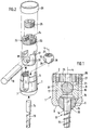
Fig. 1 und 2 gezeigten ersten Ausführungsform weist das Verankerungselement ein zylindrisch ausgebildetes Aufnahmeteil 1 mit einem ersten Ende 2 und einem gegenüberliegenden zweiten Ende 3 auf. Die beiden Enden erstrecken sich senkrecht zu einer Symmetrie- bzw. Längsachse 4. Koaxial zu der Längsachse 4 ist eine von dem ersten Ende 2 aus sich erstreckende erste koaxiale Bohrung 5 vorgesehen, die sich bis zu einem vorbestimmten Abstand von dem zweiten Ende 3 hin erstreckt. An dem zweiten Ende 3 ist eine zweite Bohrung vorgesehen, deren Durchmesser kleiner als der Durchmesser der ersten Bohrung ist. In dem gezeigten Ausführungsbeispiel ist die zweite Bohrung als eine Öffnung ausgebildet, deren Rand als hohlkugelsegementförmiger Abschnitt geformt ist, dessen Mittelpunkt zum ersten Ende 2 hin gerichtet ist. - Das Aufnahmeteil 1 weist ausgehend von dem ersten Ende 2 eine sich senkrecht zur Längsachse 3 erstreckende U-förmige Ausnehmung 7 auf mit zwei zum ersten Ende 2 hin endenden freien Schenkeln 8, 9. Angrenzend an das erste Ende 2 weisen die Schenkel ein Innengewinde 10 auf. Der Grund der U-förmigen Ausnehmung erstreckt sich bis zu einem vorgegebenen Abstand von dem zweiten Ende 3 hin. Angrenzend an das erste Ende 2 weisen die Schenkel 8, 9 außen einen Abschnitt 11 auf, dessen Außendurchmesser kleiner ist als der Außendurchmesser des angrenzenden Abschnittes des Aufnahmeteiles.
- Die mit dem Aufnahmeteil 1 zusammenwirkende Schraube 12 weist einen als Knochenschraube ausgebildeten Gewindeabschnitt 13 und einen in der in
Fig. 1 gezeigten montierten Darstellung damit verbundenen kugelsegmentförmigen Kopf 15 auf. Der Kopf weist einen Radius auf, der so bemessen ist, daß der Kopf bei der inFig. 1 gezeigten Aufnahme des Kopfes 15 in der zweiten Bohrung 6 zu einem dort gebildeten hohlkugelsegementförmigen Wandabschnitt paßt, wobei der hohlkugelsegmentförmige Abschnitt so ausgebildet ist, daß der Mittelpunkt 16 der Kugel so weit zum ersten Ende 2 hin versetzt ist, daß der Abschnitt ein Widerlager bildet und die Kugel bzw. der Kopf 15 in dem hohlkugelsegmentförmigen Abschnitt der zweiten Bohrung 6 gehalten wird. - Es ist ferner ein Druckelement 17 vorgesehen, welches zylindrisch ausgebildet ist und einen Außendurchmesser aufweist, der gerade so groß ist, daß das Druckelement in die erste Bohrung 5 einführbar und in dieser in Axialrichtung hin- und herbewegbar ist. Auf seiner, dem zweiten Ende 3 zugewandten Unterseite weist das Druckelement 17 einen zur Längsachse 4 symmetrisch ausgebildeten hohlkugelsegmentförmigen Abschnitt auf, dessen Radius dem Radius des Kopfes 5 entspricht. Das Druckelement weist eine sich quer zur Längsachse 4 erstreckende U-förmige Ausnehmung 18 auf, deren freie Schenkel sich zum ersten Ende 2 hin erstrecken. Der seitliche Durchmesser dieser U-förmigen Ausnehmung ist so gewählt, daß ein aufzunehmender Stab 19 in die Ausnehmung einsetzbar ist und in dieser seitlich geführt ist. Die Tiefe der hohlkugelsegmentförmigen Ausnehmung ist so gewählt, daß sie in einem Abstand von dem zweiten Ende 3 endet, der größer ist als der dem Radius des Kopfes 15 entsprechenden Abstandes von dem Mittelpunkt 16 zum ersten Ende 2 hin gesehen. Am Grund der U-förmigen Ausnehmung 18 schließt sich eine koaxiale Bohrung 20 an, deren Durchmesser kleiner als der Durchmesser des aufzunehmenden Stabes 19 ist.
- Wie aus
Fig. 1 ersichtlich ist, weist die U-förmige Ausnehmung 18 an ihrem zum ersten Ende 2 hin gerichteten Ende einen Abschnitt 21 auf, dessen innere Weite größer als der Durchmesser der U-förmigen Ausnehmung 18 ist. - Auf der dem ersten Ende 2 zugewandten Seite schließt sich an das Druckelement 17 eine Mutter 22 an, die ein zu dem Innengewinde 10 passendes Außengewinde 23 und zusätzlich ein Innengewinde 24 aufweist. Die Innenabmessung der Mutter 22 ist so gewählt, daß die innere Weite kleiner als der Durchmesser des Abschnittes 21 ist und größer als der Durchmesser des Stabes 19 und damit der U-förmigen Ausnehmung 18 ist. Ferner ist eine Innenmutter 25 mit einem zum Innengewinde 24 passenden Außengewinde vorgesehen. Schließlich ist eine das freie Ende angrenzend an das erste Ende 2 umfassende Hülse 26 vorgesehen, die im zusammengesetzten Zustand auf dem ringförmigen Abschnitt 11 aufsitzt, wie dieser in
Fig. 1 gezeigt ist. - Wie am besten aus
Fig. 2 zu ersehen ist, weist die Mutter 22 einen Schlitz und die Innenmutter 25 eine Sechskantöffnung zum jeweiligen getrennten Angreifen von Schraubendrehern auf. - Wie am besten aus
Fig. 2 zu ersehen ist, ist der Kopf 15 als eine an ihrem dem ersten Ende 2 zuzuwendenden Ende abgeflachte Kugel ausgebildet und weist eine zu der Längsachse 4 koaxiale Bohrung 27 auf. Der Durchmesser der Bohrung 27 ist gleich dem Außendurchmesser des Schaftes 14 und so ausgebildet, daß der Schaft in die Bohrung reibschlüssig einschiebbar ist. Wie ausFig. 2 ersichtlich ist, ist das so geformte hohlkugelsegmentförmige Element auf seiner dem abgeflachten Ende gegenüberliegenden Seite mit in Umfangsrichtung einen Abstand zueinander aufweisenden und sich parallel zur Längsachse 4 erstreckenden und bis zu dem der abgeflachten Seite gegenüberliegenden Ende reichenden Ausschnitten 28, 29 versehen. Dadurch wird erreicht, daß der dem ersten Ende 2 abgewandte Rand 30 zum Einführen des Schaftes 14 federnd nach außen nachgebbar ausgebildet ist. - Im Betrieb wird zunächst die Schraube 12 in den Knochen bzw. den Wirbel eingeschraubt. Zu diesem Zweck weist der Schaft 14 bekannte Eingriffsmöglichkeiten wie etwa einen Innensechskant auf. Dann kürzt der Operateur den Schaft 14 auf die gewünschte Länge und setzt zunächst das Aufnahmeteil mit der zweiten Bohrung auf den Schaft 14 und führt dann den Kopf von dem ersten Ende 2 her auf den Schaft 14, so daß der Schaft 14 vom federnd nachgebenden Rand 30 her in die Bohrung 27 eingeführt wird und der Kopf den Schaft in der in
Fig. 1 gezeigten Weise einschließt. Der Kopf 15 und der Schaft 14 sind reibschlüssig miteinander verbunden. Anschließend wird das Druckelement 17 eingesetzt und durch Einschrauben der Mutter 22 so auf den Kopf 15 gedrückt, daß dieser eine gewünschte Drehstabilisierung erfährt. Die Hülse 26 wird aufgebracht und dann wird mit Hilfe der Innenmutter 25 der Stab 19 fixiert. Der Stab 19 übt über das Druckelement 17 einen zusätzlichen Druck auf den Kopf 15 aus. - Durch den vom ersten Ende 2 her gesehen ausgeübten Druck auf den Kopf 15 wird der geschlitzte Kopf 15 einerseits mit dem Schaft 14 bewegungsfest verbunden bzw. verklemmt, gleichzeitig wird der Kopf in seiner Drehstellung arretiert.
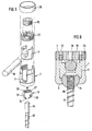
- Die in
Fig. 3 gezeigte zweite Ausführungsform unterscheidet sich von der zuvor beschriebenen Ausführungsform durch einen abgewandelten Kopf 31. Dieser weist wie bei der ersten Ausführungsform in Umfangsrichtung zueinander versetzte Ausschnitte 28 auf, die an dem dem ersten Ende abgewandten Rand 34 frei enden und einen Abstand von dem dem ersten Ende 2 zugewandten Rand 32 aufweisen. Es ist jedoch ein Ausschnitt 33 vorgesehen, der sich vollständig von dem Rand 32 bis zum gegenüberliegenden Rand 34 erstreckt, mit der Folge, daß das so gebildete Kugelsegment um ein durch die Breite des Ausschnittes 33 bestimmtes Ausmaß zusammendrückbar ist. Die Breite des so gebildeten Schlitzes 33 ist so gewählt, daß der Kopf 31 zunächst so weit zusammendrückbar ist, daß er in der inFig. 3 gezeigten Richtung vom zweiten Ende 2 her in die erste Bohrung 5 hineindrückbar ist und daß dann der Schaft 14 in den Kopf in der gleichen Weise wie oben beschrieben einschiebbar ist und auf die gleiche Weise in verklemmter Position gehalten wird. - Der Schaft 14 der Schraube hat vorzugsweise die in den
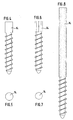
Fig. 4 und 5 gezeigte zylindrische Form oder auch eine in denFig. 6 und 7 gezeigte mehreckige Form. In letzterer ist der Querschnitt achteckig ausgebildet. Eine weitere bevorzugte Ausführungsform ist inFig. 8 gezeigt. Der Schaft ist hier zylindrisch ausgebildet und weist eine rauhe Oberfläche auf, die das Ineingriffbringen zwischen Kugel 15 und Schaft erleichtert. - Die in
Fig. 9 gezeigte weitere Ausführungsform stimmt in allen Merkmalen, die das Aufnahmeteil 1, das Druckelement 17, den Stab 19 und die Schrauben 22 und 25 betreffen, mit den vorhergehenden Ausführungsbeispielen überein. Der einzige Unterschied besteht darin, daß der Kopf 15 als ein Kugelsegment ausgebildet ist, welches in seinen äußeren Abmessungen den beiden vorhergehenden Kugelsegmenten entspricht, jedoch keine Ausschnitte 28 oder 33 aufweist. Statt dessen weist das Kugelsegment auf der Innenseite seiner Bohrung 27 ein Innengewinde auf. Anstelle des Schaftes 14 ist ein Schaft 35 mit einem Gewinde vorgesehen, welches zu dem Innengewinde des Kopfes passend ausgebildet ist. Die Bohrung ist als eine Sackbohrung ausgebildet, die an dem dem freien Ende 2 zugewandten Ende endet oder dort einen Anschlag aufweist, so daß die Schraube nur so weit in die gezeigte Stellung einschraubbar ist, in der sie nicht aus dem Kugelsegment an dessen abgeflachter Seite heraussteht. Wie inFig. 9 gezeigt ist, sind das Innengewinde des Kopfes 15 und das entsprechende Außengewinde des Schaftes 35 in der Richtung vorzugsweise entgegengesetzt zur Richtung des Gewindes des Gewindeabschnittes 13 der Knochenschraube ausgebildet. - Der Betrieb erfolgt in gleicher Weise wie bei dem zuerst beschriebenen Ausführungsbeispiel, wobei nach dem Kürzen des Schaftes 35 der Kopf 15 vom ersten Ende 2 des Aufnahmeteils 1 her in die Bohrung 5 eingeführt und auf den vom zweiten Ende 3 her eingeführten Schaft 35 aufgeschraubt wird.
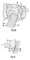
- Die in den
Figuren 10 und 11 gezeigte weitere Auführungsform stimmt in allen Merkmalen, die das Aufnahmeteil 1, das Druckelement 17, den Stab 19 und die Schrauben 22 und 25 betreffen, mit den vorhergehenden Ausführungsbeispielen überein. Anstelle des Schafts 35 und des Kopfes 15 der Ausführungsform nachFig. 9 , welche die zusammenwirkenden Gewinde aufweist, ist bei dieser Ausführungsform der Schaft 37 in einem Abschnitt angrenzend an das dem Knochengewindeabschnitt gegenüberliegenden Ende als Wellenstab ausgebildet. Die Außenfläche des Schaftes weist in Umfangsrichtung verlaufende Wellentäler 38 und dazwischenliegende Wellenkämme 39 auf. Die Wellentäler 38 haben in Umfangsrichtung gesehen einen kreisabschnittförmigen Querschnitt und ihr Durchmesser auf halber Höhe bzw. Tiefe ist deutlich größer als der entsprechende Durchmesser des Wellenbergs 39, so dass die Wellenberge 39 spitz sind im Verhältnis zu dem Grund der Wellentäler 38. Der Kopf 15 ist als ein Kugelsegment ausgebildet, welches in seinen äußeren Abmessungen den zuvor genannten Kugelsegmenten entspricht, das jedoch keine Ausschnitte 28 oder 33 aufweist. Auf der Innenseite seiner Bohrung 27 weist das Kugelsegment des Kopfes 15 in Umfangsrichtung verlaufende Wellen mit Wellentälern 40 und Wellenkämmen 41 auf, die jeweils den Wellenkämmen 39 bzw. den Wellentälern 38 des Schaftes 37 entsprechen. Zwischen den Wellentälern 38 und den Wellenkämmen 39 des Schaftes einerseits und den entsprechenden Wellenkämmen 40 und Wellentälern 41 andererseits ist ein kleiner Zwischenraum, so daß der Schaft in das Kugelsegment einführbar ist. - Der Betrieb erfolgt in ähnlicher Weise wie bei dem Ausführungsbeispiel gemäß
Fig. 9 . Das Kürzen des gewellten Schaftes 37 ist jedoch bei dieser Ausführungsform einfacher als das Kürzen des Schaftes 35 mit dem Gewinde gemäßFig. 9 , da die Wellentäler 38 ein leichtes Abschneiden ermöglichen, während bei dem Schaft 35 mit dem Gewinde gemäßFig. 9 darauf geachtet werden muß, daß das Gewinde nicht zerstört wird. Nach dem Kürzen des Schaftes 37 wird der Kopf 15 von dem ersten Ende 2 des Aufnahmeteils 1 in die Bohrung 5 eingeführt und auf den Schaft 37 aufgedrückt. Dabei wirken die Wellen des Schaftes 37 und die entsprechenden der Bohrung 27 des Kopfes 15 zusammen, so daß der Schaft gehalten wird. - In den oben beschriebenen Ausführungsbeispielen wird der Kopf 15 jeweils durch einen mit dem Aufnahmeteil 1 einstückig ausgebildeten Rand gehalten. Ein solches Widerlager kann auch auf andere Weise gebildet werden, beispielsweise ist es möglich, die erste Bohrung 5 vollständig durch das Aufnahmeteil 1 hindurch zu bohren und dann angrenzend an das zweite Ende ein den Kopf 15 aufnehmendes Halteelement einzuspannen.
- In den oben beschriebenen Ausführungsbeispielen weist das Aufnahmeteil stets die Mutter 22 und eine Innenmutter 25 sowie eine Hülse 26 auf. Diese Fixierung kann in bekannter Weise auch anders ausgebildet sein. Insbesondere kann gegebenenfalls auch lediglich eine Innenmutter vorgesehen sein.
- Bei dem oben unter Bezugnahme auf
Fig. 9 beschriebenen Ausführungsbeispiel weist der Kopf 15 keine Ausschnitte 28, 33 auf. In einer weiteren Ausführungsform weisen Kopf 15 und Schaft 35 wie bei der inFig. 9 gezeigten Darstellung zueinander passende Gewinde auf. Der Kopf 15 weist jedoch zusätzlich den sich über die gesamte Länge erstreckenden Ausschnitt 33, so daß wie bei der inFig. 3 gezeigten Ausführungsform der Kopf ohne eingeschraubten Schaft von dem Rand 3 aus durch Zusammendrücken in das Aufnahmeteil einschiebbar ist und dann auf den ebenfalls vom Ende 3 her einführbaren Schaft 35 durch Einschrauben aufnimmt und mit diesem verbunden wird. Der Schlitz führt beim Aufsetzen der Druckelemente bzw. beim Ausüben des Druckes auf den Kopf 15 dazu, daß gleichzeitig der Kopf und der Schaft 35 fester zusammengedrückt werden als ohne einen solchen Schlitz. - In einer weiteren Ausführungsform können zusätzlich noch Ausschnitte 28 in der in
Fig. 3 gezeigten Weise vorgesehen sein, um so ein noch stärkeres Anpressen an den Gewindeschaft 35 zu bewirken.
Claims (10)
- Verankerungselement mit einer einen Schaft mit Gewindeabschnitt (13) und einen als kugelsegmentförmiger Abschnitt ausgebildeten Kopf (15) aufweisenden Schraube (12) und einem Aufnahmeteil (1) zum Verbinden der Schraube (12) mit einem Stab (19), wobei das Aufnahmeteil (1)
ein erstes Ende (2) und ein diesem gegenüberliegendes zweites Ende (3), eine durch die beiden Enden (2, 3) gehende Längsachse (4),
eine zur Längsachse (4) koaxiale Bohrung (5), einen in einem an das erste Ende (2) angrenzenden ersten Bereich mit einem im wesentlichen U-förmigen Querschnitt (7) mit zwei freien ein Gewinde aufweisenden Schenkeln (8, 9) zur Aufnahme des einzusetzenden Stabes (19), einen an das andere Ende (3) angrenzenden Bereich zur Aufnahme des Kopfes (15) und
ein auf den Stab (19) bzw. auf den Kopf (15) Druck ausübendes Element (22, 17) aufweist,
dadurch gekennzeichnet, daß
der Gewindeabschnitt (13) und der Kopf (15) als separate Teile ausgebildet sind und daß
der Kopf (15) auf seiner dem Gewindeabschnitt (13) zugewandten Seite einen federnd nachgebenden Rand aufweist, wobei durch einen vom ersten Ende (2) her auf den Kopf (15) ausgeübten Druck der Kopf durch den federnden Rand einerseits mit dem Schaft verklemmt und gleichzeitig der Kopf in seiner Drehstellung arretiert wird. - Verankerungselement nach Anspruch 1, dadurch gekennzeichnet, daß der Gewindeabschnitt (13) an dem kopfseitigen Ende einen Schaft (14) aufweist.
- Verankerungselement nach einem der Ansprüche 1 bis 3, dadurch gekennzeichnet, daß der dem Gewindeabschnitt zugewandte Rand (34) eine oder mehrere zur Symmetrieachse (4) parallel gerichtete und umfangsmäßig verteilte Durchbrechungen bzw. Ausnehmungen (28, 29, 33) aufweist.
- Verankerungselement nach Anspruch 4, dadurch gekennzeichnet, daß eine Durchbrechung (33) sich in Richtung parallel zur Symmetrieachse (4) gesehen über die gesamte Wandlänge erstreckt.
- Verankerungselement nach einem der Ansprüche 1 bis 5, dadurch gekennzeichnet, daß der Kopf (15) eine zur Symmetrieachse koaxiale Bohrung (27) aufweist.
- Verankerungselement nach Anspruch 6, dadurch gekennzeichnet, daß die Bohrung (27) zylindrisch ausgebildet ist.
- Verankerungselement nach einem der Ansprüche 2 bis 7, dadurch gekennzeichnet, daß der Schaft (14) eine rauhe Oberfläche aufweist.
- Verankerungselement nach einem der Ansprüche 2 bis 8, dadurch gekennzeichnet, daß der Schaft (14) mehreckig ausgebildet ist.
- Verankerungselement nach einem der Ansprüche 1 bis 6, dadurch gekennzeichnet, daß der Kopf (15) in der Bohrung ein Innengewinde und der Schaft (35) ein dazu passendes Außengewinde aufweist.
- Verankerungselement nach einem der Ansprüche 1 bis 6, dadurch gekennzeichnet, daß der Kopf (15) in der Bohrung in Umfangsrichtung gewellt ausgebildet ist und der Schaft (37) an seiner Außenseite eine entsprechende Wellung aufweist.
Applications Claiming Priority (3)
| Application Number | Priority Date | Filing Date | Title |
|---|---|---|---|
| DE10115014 | 2001-03-27 | ||
| DE10115014A DE10115014A1 (de) | 2001-03-27 | 2001-03-27 | Verankerungselement |
| PCT/EP2002/001284 WO2002076314A1 (de) | 2001-03-27 | 2002-02-07 | Verankerungselement |
Publications (2)
| Publication Number | Publication Date |
|---|---|
| EP1372502A1 EP1372502A1 (de) | 2004-01-02 |
| EP1372502B1 true EP1372502B1 (de) | 2008-04-16 |
Family
ID=7679218
Family Applications (1)
| Application Number | Title | Priority Date | Filing Date |
|---|---|---|---|
| EP02718105A Expired - Lifetime EP1372502B1 (de) | 2001-03-27 | 2002-02-07 | Verankerungselement |
Country Status (6)
| Country | Link |
|---|---|
| US (2) | US6835196B2 (de) |
| EP (1) | EP1372502B1 (de) |
| JP (1) | JP4098089B2 (de) |
| KR (1) | KR100815218B1 (de) |
| DE (2) | DE10115014A1 (de) |
| WO (1) | WO2002076314A1 (de) |
Families Citing this family (300)
| Publication number | Priority date | Publication date | Assignee | Title |
|---|---|---|---|---|
| US20060241602A1 (en) * | 2000-06-06 | 2006-10-26 | Jackson Roger P | Hooked transverse connector for spinal implant system |
| US7833250B2 (en) | 2004-11-10 | 2010-11-16 | Jackson Roger P | Polyaxial bone screw with helically wound capture connection |
| US20060025771A1 (en) * | 2000-08-23 | 2006-02-02 | Jackson Roger P | Helical reverse angle guide and advancement structure with break-off extensions |
| US7837716B2 (en) * | 2000-08-23 | 2010-11-23 | Jackson Roger P | Threadform for medical implant closure |
| US20060083603A1 (en) * | 2000-08-23 | 2006-04-20 | Jackson Roger P | Reverse angled threadform with anti-splay clearance |
| US6743231B1 (en) | 2000-10-02 | 2004-06-01 | Sulzer Spine-Tech Inc. | Temporary spinal fixation apparatuses and methods |
| US6726689B2 (en) | 2002-09-06 | 2004-04-27 | Roger P. Jackson | Helical interlocking mating guide and advancement structure |
| US8377100B2 (en) | 2000-12-08 | 2013-02-19 | Roger P. Jackson | Closure for open-headed medical implant |
| FR2823095B1 (fr) | 2001-04-06 | 2004-02-06 | Ldr Medical | Dispositif d'osteosynthese du rachis et procede de mise en place |
| US8353932B2 (en) * | 2005-09-30 | 2013-01-15 | Jackson Roger P | Polyaxial bone anchor assembly with one-piece closure, pressure insert and plastic elongate member |
| US10258382B2 (en) | 2007-01-18 | 2019-04-16 | Roger P. Jackson | Rod-cord dynamic connection assemblies with slidable bone anchor attachment members along the cord |
| US8292926B2 (en) | 2005-09-30 | 2012-10-23 | Jackson Roger P | Dynamic stabilization connecting member with elastic core and outer sleeve |
| US7862587B2 (en) | 2004-02-27 | 2011-01-04 | Jackson Roger P | Dynamic stabilization assemblies, tool set and method |
| US10729469B2 (en) | 2006-01-09 | 2020-08-04 | Roger P. Jackson | Flexible spinal stabilization assembly with spacer having off-axis core member |
| GB2393189B (en) * | 2001-07-19 | 2005-06-15 | Trikon Holdings Ltd | Depositing a tantalum film |
| DE10136129A1 (de) * | 2001-07-27 | 2003-02-20 | Biedermann Motech Gmbh | Knochenschraube und Befestigungswerkzeug für diese |
| DE10157814B4 (de) * | 2001-11-27 | 2004-12-02 | Biedermann Motech Gmbh | Verschlußeinrichtung zum Sichern eines stabförmigen Elements in einem mit einem Schaft verbundenen Halteelement |
| DE10164323C1 (de) * | 2001-12-28 | 2003-06-18 | Biedermann Motech Gmbh | Verschlußeinrichtung zum Sichern eines stabförmigen Elements in einem mit einem Schaft verbundenen Halteelement |
| US7066937B2 (en) * | 2002-02-13 | 2006-06-27 | Endius Incorporated | Apparatus for connecting a longitudinal member to a bone portion |
| US7879075B2 (en) * | 2002-02-13 | 2011-02-01 | Zimmer Spine, Inc. | Methods for connecting a longitudinal member to a bone portion |
| US11224464B2 (en) | 2002-05-09 | 2022-01-18 | Roger P. Jackson | Threaded closure with inwardly-facing tool engaging concave radiused structures and axial through-aperture |
| US8876868B2 (en) | 2002-09-06 | 2014-11-04 | Roger P. Jackson | Helical guide and advancement flange with radially loaded lip |
| US8257402B2 (en) | 2002-09-06 | 2012-09-04 | Jackson Roger P | Closure for rod receiving orthopedic implant having left handed thread removal |
| US8282673B2 (en) | 2002-09-06 | 2012-10-09 | Jackson Roger P | Anti-splay medical implant closure with multi-surface removal aperture |
| DE10246177A1 (de) | 2002-10-02 | 2004-04-22 | Biedermann Motech Gmbh | Verankerungselement |
| FR2845269B1 (fr) * | 2002-10-07 | 2005-06-24 | Spine Next Sa | Systeme de fixation a plaque |
| US7780664B2 (en) | 2002-12-10 | 2010-08-24 | Depuy Products, Inc. | Endosteal nail |
| DE10260222B4 (de) * | 2002-12-20 | 2008-01-03 | Biedermann Motech Gmbh | Rohrförmiges Element für ein in der Wirbelsäulen- oder der Knochenchirurgie zu verwendendes Implantat und Implantat mit einem solchen Element |
| US7887539B2 (en) | 2003-01-24 | 2011-02-15 | Depuy Spine, Inc. | Spinal rod approximators |
| US20040186473A1 (en) * | 2003-03-21 | 2004-09-23 | Cournoyer John R. | Spinal fixation devices of improved strength and rigidity |
| US8052724B2 (en) * | 2003-06-18 | 2011-11-08 | Jackson Roger P | Upload shank swivel head bone screw spinal implant |
| US6964666B2 (en) | 2003-04-09 | 2005-11-15 | Jackson Roger P | Polyaxial bone screw locking mechanism |
| US6716214B1 (en) | 2003-06-18 | 2004-04-06 | Roger P. Jackson | Polyaxial bone screw with spline capture connection |
| US7621918B2 (en) | 2004-11-23 | 2009-11-24 | Jackson Roger P | Spinal fixation tool set and method |
| US8540753B2 (en) | 2003-04-09 | 2013-09-24 | Roger P. Jackson | Polyaxial bone screw with uploaded threaded shank and method of assembly and use |
| US7473267B2 (en) * | 2003-04-25 | 2009-01-06 | Warsaw Orthopedic, Inc. | System and method for minimally invasive posterior fixation |
| US20050177164A1 (en) * | 2003-05-02 | 2005-08-11 | Carmen Walters | Pedicle screw devices, systems and methods having a preloaded set screw |
| US20050182401A1 (en) * | 2003-05-02 | 2005-08-18 | Timm Jens P. | Systems and methods for spine stabilization including a dynamic junction |
| US20050182400A1 (en) * | 2003-05-02 | 2005-08-18 | Jeffrey White | Spine stabilization systems, devices and methods |
| US7615068B2 (en) * | 2003-05-02 | 2009-11-10 | Applied Spine Technologies, Inc. | Mounting mechanisms for pedicle screws and related assemblies |
| US7377923B2 (en) | 2003-05-22 | 2008-05-27 | Alphatec Spine, Inc. | Variable angle spinal screw assembly |
| US7776067B2 (en) | 2005-05-27 | 2010-08-17 | Jackson Roger P | Polyaxial bone screw with shank articulation pressure insert and method |
| US8377102B2 (en) | 2003-06-18 | 2013-02-19 | Roger P. Jackson | Polyaxial bone anchor with spline capture connection and lower pressure insert |
| US7967850B2 (en) | 2003-06-18 | 2011-06-28 | Jackson Roger P | Polyaxial bone anchor with helical capture connection, insert and dual locking assembly |
| US20100211114A1 (en) * | 2003-06-18 | 2010-08-19 | Jackson Roger P | Polyaxial bone anchor with shelf capture connection |
| US7204838B2 (en) * | 2004-12-20 | 2007-04-17 | Jackson Roger P | Medical implant fastener with nested set screw and method |
| US8814911B2 (en) | 2003-06-18 | 2014-08-26 | Roger P. Jackson | Polyaxial bone screw with cam connection and lock and release insert |
| US7766915B2 (en) * | 2004-02-27 | 2010-08-03 | Jackson Roger P | Dynamic fixation assemblies with inner core and outer coil-like member |
| US8366753B2 (en) | 2003-06-18 | 2013-02-05 | Jackson Roger P | Polyaxial bone screw assembly with fixed retaining structure |
| US8092500B2 (en) | 2007-05-01 | 2012-01-10 | Jackson Roger P | Dynamic stabilization connecting member with floating core, compression spacer and over-mold |
| US8398682B2 (en) | 2003-06-18 | 2013-03-19 | Roger P. Jackson | Polyaxial bone screw assembly |
| US7322981B2 (en) | 2003-08-28 | 2008-01-29 | Jackson Roger P | Polyaxial bone screw with split retainer ring |
| US8926670B2 (en) | 2003-06-18 | 2015-01-06 | Roger P. Jackson | Polyaxial bone screw assembly |
| US8257398B2 (en) | 2003-06-18 | 2012-09-04 | Jackson Roger P | Polyaxial bone screw with cam capture |
| AU2006235961A1 (en) * | 2003-06-18 | 2006-11-30 | Roger P. Jackson | Polyaxial bone screw with spline capture connection |
| US8137386B2 (en) | 2003-08-28 | 2012-03-20 | Jackson Roger P | Polyaxial bone screw apparatus |
| US7087057B2 (en) | 2003-06-27 | 2006-08-08 | Depuy Acromed, Inc. | Polyaxial bone screw |
| US7291151B2 (en) * | 2003-07-25 | 2007-11-06 | Traiber, S.A. | Vertebral fixation device for the treatment of spondylolisthesis |
| DE50313414D1 (de) | 2003-08-08 | 2011-02-24 | Synthes Gmbh | Klemmvorrichtung |
| FR2859095B1 (fr) * | 2003-09-01 | 2006-05-12 | Ldr Medical | Implant d'ancrage osseux a tete polyaxiale et procede de mise en place de l'implant |
| AU2003258438B2 (en) * | 2003-09-08 | 2009-07-09 | Synthes Gmbh | Longitudinal support |
| FR2860138A1 (fr) | 2003-09-26 | 2005-04-01 | Stryker Spine | Assemblage et procede de fixation d'os |
| US7967826B2 (en) | 2003-10-21 | 2011-06-28 | Theken Spine, Llc | Connector transfer tool for internal structure stabilization systems |
| US7588575B2 (en) | 2003-10-21 | 2009-09-15 | Innovative Spinal Technologies | Extension for use with stabilization systems for internal structures |
| US11419642B2 (en) | 2003-12-16 | 2022-08-23 | Medos International Sarl | Percutaneous access devices and bone anchor assemblies |
| US7527638B2 (en) | 2003-12-16 | 2009-05-05 | Depuy Spine, Inc. | Methods and devices for minimally invasive spinal fixation element placement |
| US7179261B2 (en) | 2003-12-16 | 2007-02-20 | Depuy Spine, Inc. | Percutaneous access devices and bone anchor assemblies |
| US20060161260A1 (en) * | 2003-12-23 | 2006-07-20 | Gareth Thomas | Total wrist prosthesis |
| EP1699371A4 (de) * | 2003-12-30 | 2008-09-24 | Depuy Spine Sarl | Knochenankeranordnungen |
| US20050154393A1 (en) * | 2003-12-30 | 2005-07-14 | Thomas Doherty | Bone anchor assemblies and methods of manufacturing bone anchor assemblies |
| US7195633B2 (en) * | 2004-01-08 | 2007-03-27 | Robert J. Medoff | Fracture fixation system |
| US7678137B2 (en) * | 2004-01-13 | 2010-03-16 | Life Spine, Inc. | Pedicle screw constructs for spine fixation systems |
| US7993373B2 (en) * | 2005-02-22 | 2011-08-09 | Hoy Robert W | Polyaxial orthopedic fastening apparatus |
| US7160300B2 (en) | 2004-02-27 | 2007-01-09 | Jackson Roger P | Orthopedic implant rod reduction tool set and method |
| US8066739B2 (en) | 2004-02-27 | 2011-11-29 | Jackson Roger P | Tool system for dynamic spinal implants |
| US8152810B2 (en) | 2004-11-23 | 2012-04-10 | Jackson Roger P | Spinal fixation tool set and method |
| AU2004317551B2 (en) | 2004-02-27 | 2008-12-04 | Roger P. Jackson | Orthopedic implant rod reduction tool set and method |
| US7789896B2 (en) * | 2005-02-22 | 2010-09-07 | Jackson Roger P | Polyaxial bone screw assembly |
| DE102004010380A1 (de) | 2004-03-03 | 2005-09-22 | Biedermann Motech Gmbh | Verankerungselement und Stabilisierungseinrichtung zur dynamischen Stabilisierung von Wirbeln bzw. Knochen mit einem solchen Verankerungselement |
| US7214227B2 (en) * | 2004-03-22 | 2007-05-08 | Innovative Spinal Technologies | Closure member for a medical implant device |
| US7686833B1 (en) * | 2004-04-02 | 2010-03-30 | Muhanna Nabil L | Ball jointed pedicle screw and rod system |
| US7503924B2 (en) | 2004-04-08 | 2009-03-17 | Globus Medical, Inc. | Polyaxial screw |
| US8475495B2 (en) | 2004-04-08 | 2013-07-02 | Globus Medical | Polyaxial screw |
| WO2005102195A1 (en) | 2004-04-20 | 2005-11-03 | Allez Spine, Llc | Pedicle screw assembly |
| DE102004027881B4 (de) * | 2004-05-28 | 2006-06-01 | Aesculap Ag & Co. Kg | Knochenschraube und Osteosynthesevorrichtung |
| US7744635B2 (en) * | 2004-06-09 | 2010-06-29 | Spinal Generations, Llc | Spinal fixation system |
| US7938848B2 (en) * | 2004-06-09 | 2011-05-10 | Life Spine, Inc. | Spinal fixation system |
| US8021398B2 (en) * | 2004-06-09 | 2011-09-20 | Life Spine, Inc. | Spinal fixation system |
| US7857834B2 (en) * | 2004-06-14 | 2010-12-28 | Zimmer Spine, Inc. | Spinal implant fixation assembly |
| US7186255B2 (en) * | 2004-08-12 | 2007-03-06 | Atlas Spine, Inc. | Polyaxial screw |
| US20060058787A1 (en) * | 2004-08-24 | 2006-03-16 | Stryker Spine | Spinal implant assembly |
| US7651502B2 (en) | 2004-09-24 | 2010-01-26 | Jackson Roger P | Spinal fixation tool set and method for rod reduction and fastener insertion |
| JP2008517733A (ja) * | 2004-10-25 | 2008-05-29 | アルファスパイン インコーポレイテッド | ペディクルねじシステムおよび、該システムの組立/設置法 |
| US7604655B2 (en) * | 2004-10-25 | 2009-10-20 | X-Spine Systems, Inc. | Bone fixation system and method for using the same |
| US7691129B2 (en) | 2004-10-27 | 2010-04-06 | Felix Brent A | Spinal stabilizing system |
| US7513905B2 (en) * | 2004-11-03 | 2009-04-07 | Jackson Roger P | Polyaxial bone screw |
| US7572279B2 (en) * | 2004-11-10 | 2009-08-11 | Jackson Roger P | Polyaxial bone screw with discontinuous helically wound capture connection |
| CA2586361A1 (en) | 2004-11-10 | 2006-05-18 | Roger P. Jackson | Helical guide and advancement flange with break-off extensions |
| US8926672B2 (en) * | 2004-11-10 | 2015-01-06 | Roger P. Jackson | Splay control closure for open bone anchor |
| US9216041B2 (en) | 2009-06-15 | 2015-12-22 | Roger P. Jackson | Spinal connecting members with tensioned cords and rigid sleeves for engaging compression inserts |
| US8444681B2 (en) | 2009-06-15 | 2013-05-21 | Roger P. Jackson | Polyaxial bone anchor with pop-on shank, friction fit retainer and winged insert |
| US8308782B2 (en) | 2004-11-23 | 2012-11-13 | Jackson Roger P | Bone anchors with longitudinal connecting member engaging inserts and closures for fixation and optional angulation |
| EP1814470B1 (de) * | 2004-11-23 | 2011-12-14 | Roger P. Jackson | Polyaxiale knochenschraube mit mehrteiliger schaftfixierung |
| US9393047B2 (en) | 2009-06-15 | 2016-07-19 | Roger P. Jackson | Polyaxial bone anchor with pop-on shank and friction fit retainer with low profile edge lock |
| US9980753B2 (en) | 2009-06-15 | 2018-05-29 | Roger P Jackson | pivotal anchor with snap-in-place insert having rotation blocking extensions |
| WO2006057837A1 (en) | 2004-11-23 | 2006-06-01 | Jackson Roger P | Spinal fixation tool attachment structure |
| US9168069B2 (en) | 2009-06-15 | 2015-10-27 | Roger P. Jackson | Polyaxial bone anchor with pop-on shank and winged insert with lower skirt for engaging a friction fit retainer |
| US7875065B2 (en) | 2004-11-23 | 2011-01-25 | Jackson Roger P | Polyaxial bone screw with multi-part shank retainer and pressure insert |
| WO2006058221A2 (en) | 2004-11-24 | 2006-06-01 | Abdou Samy M | Devices and methods for inter-vertebral orthopedic device placement |
| US7306606B2 (en) * | 2004-12-15 | 2007-12-11 | Orthopaedic Innovations, Inc. | Multi-axial bone screw mechanism |
| US7901437B2 (en) | 2007-01-26 | 2011-03-08 | Jackson Roger P | Dynamic stabilization member with molded connection |
| US8403962B2 (en) * | 2005-02-22 | 2013-03-26 | Roger P. Jackson | Polyaxial bone screw assembly |
| US7476239B2 (en) * | 2005-05-10 | 2009-01-13 | Jackson Roger P | Polyaxial bone screw with compound articulation |
| US10076361B2 (en) | 2005-02-22 | 2018-09-18 | Roger P. Jackson | Polyaxial bone screw with spherical capture, compression and alignment and retention structures |
| US20240008902A1 (en) * | 2005-02-22 | 2024-01-11 | Roger P. Jackson | Pivotal bone anchor assembly with cannulated shank having a planar top surface and method of assembly |
| US7951172B2 (en) | 2005-03-04 | 2011-05-31 | Depuy Spine Sarl | Constrained motion bone screw assembly |
| US7951175B2 (en) * | 2005-03-04 | 2011-05-31 | Depuy Spine, Inc. | Instruments and methods for manipulating a vertebra |
| US7794481B2 (en) * | 2005-04-22 | 2010-09-14 | Warsaw Orthopedic, Inc. | Force limiting coupling assemblies for spinal implants |
| US7951171B2 (en) * | 2005-05-04 | 2011-05-31 | K2M, Inc. | Polyaxial surgical rod fixation assembly |
| US7951198B2 (en) * | 2005-05-10 | 2011-05-31 | Acumed Llc | Bone connector with pivotable joint |
| EP1883359A2 (de) * | 2005-05-25 | 2008-02-06 | AlpineSpine LLC | Niedrigprofil-pedikelschraube und stangenanordnung |
| EP1741396B1 (de) * | 2005-07-08 | 2009-09-23 | BIEDERMANN MOTECH GmbH | Knochenverankerungsvorrichtung |
| US7766946B2 (en) * | 2005-07-27 | 2010-08-03 | Frank Emile Bailly | Device for securing spinal rods |
| US7717943B2 (en) | 2005-07-29 | 2010-05-18 | X-Spine Systems, Inc. | Capless multiaxial screw and spinal fixation assembly and method |
| JP5084195B2 (ja) * | 2005-08-03 | 2012-11-28 | ビーダーマン・モテーク・ゲゼルシャフト・ミット・ベシュレンクタ・ハフツング | 骨固着装置 |
| US7625394B2 (en) * | 2005-08-05 | 2009-12-01 | Warsaw Orthopedic, Inc. | Coupling assemblies for spinal implants |
| US7905909B2 (en) | 2005-09-19 | 2011-03-15 | Depuy Products, Inc. | Bone stabilization system including multi-directional threaded fixation element |
| US8105368B2 (en) | 2005-09-30 | 2012-01-31 | Jackson Roger P | Dynamic stabilization connecting member with slitted core and outer sleeve |
| US7686835B2 (en) * | 2005-10-04 | 2010-03-30 | X-Spine Systems, Inc. | Pedicle screw system with provisional locking aspects |
| US7927359B2 (en) * | 2005-10-06 | 2011-04-19 | Paradigm Spine, Llc | Polyaxial screw |
| US20070118117A1 (en) * | 2005-10-20 | 2007-05-24 | Ebi, L.P. | Bone fixation assembly |
| US7722651B2 (en) | 2005-10-21 | 2010-05-25 | Depuy Spine, Inc. | Adjustable bone screw assembly |
| GB0521582D0 (en) | 2005-10-22 | 2005-11-30 | Depuy Int Ltd | An implant for supporting a spinal column |
| US8100946B2 (en) | 2005-11-21 | 2012-01-24 | Synthes Usa, Llc | Polyaxial bone anchors with increased angulation |
| US7704271B2 (en) | 2005-12-19 | 2010-04-27 | Abdou M Samy | Devices and methods for inter-vertebral orthopedic device placement |
| WO2007075454A1 (en) * | 2005-12-19 | 2007-07-05 | Synthes (U.S.A) | Polyaxial bone anchor with headless pedicle screw |
| KR200410476Y1 (ko) * | 2005-12-21 | 2006-03-07 | (주)베리안 | 척추경 나사못 |
| EP2055251B1 (de) | 2005-12-23 | 2011-08-17 | BIEDERMANN MOTECH GmbH | Knochenverankerungselement |
| WO2007081986A2 (en) | 2006-01-10 | 2007-07-19 | Life Spine, Inc. | Pedicle screw constructs and spinal rod attachment assemblies |
| GB0600662D0 (en) | 2006-01-13 | 2006-02-22 | Depuy Int Ltd | Spinal support rod kit |
| US8348952B2 (en) | 2006-01-26 | 2013-01-08 | Depuy International Ltd. | System and method for cooling a spinal correction device comprising a shape memory material for corrective spinal surgery |
| SE529853C2 (sv) * | 2006-03-30 | 2007-12-11 | Atlas Copco Tools Ab | Monteringsanordning för fastsättning av ett element på ett rörformigt organ |
| EP1839606B1 (de) * | 2006-03-31 | 2008-11-26 | BIEDERMANN MOTECH GmbH | Verriegelungsaufbau zur Sicherung eines Stabelements in einem Aufnahmeteil zur Verwendung in der Wirbensäulenchirurgie oder Traumatologie, Knochenverankerungsvorrichtung mit einem solchen Verriegelungsaufbau und Werkzeug dafür |
| WO2007114834A1 (en) | 2006-04-05 | 2007-10-11 | Dong Myung Jeon | Multi-axial, double locking bone screw assembly |
| US7758584B2 (en) | 2006-04-11 | 2010-07-20 | Synthes Usa, Llc | Minimally invasive fixation system |
| US20080015576A1 (en) * | 2006-04-28 | 2008-01-17 | Whipple Dale E | Large diameter bone anchor assembly |
| US8361129B2 (en) | 2006-04-28 | 2013-01-29 | Depuy Spine, Inc. | Large diameter bone anchor assembly |
| US8133262B2 (en) | 2006-04-28 | 2012-03-13 | Depuy Spine, Inc. | Large diameter bone anchor assembly |
| EP2078506A4 (de) * | 2006-06-05 | 2011-11-09 | Traiber S L | Vorrichtung zur befestigung von wirbeln und werkzeug zur anbringung der vorrichtung |
| US8277485B2 (en) * | 2006-06-07 | 2012-10-02 | Spinadyne, Inc. | Pedicle screw system |
| WO2008008511A2 (en) | 2006-07-14 | 2008-01-17 | Laszlo Garamszegi | Pedicle screw assembly with inclined surface seat |
| US8388660B1 (en) | 2006-08-01 | 2013-03-05 | Samy Abdou | Devices and methods for superior fixation of orthopedic devices onto the vertebral column |
| EP1891904B1 (de) * | 2006-08-24 | 2013-12-25 | Biedermann Technologies GmbH & Co. KG | Knochenverankerungsvorrichtung |
| US7918857B2 (en) | 2006-09-26 | 2011-04-05 | Depuy Spine, Inc. | Minimally invasive bone anchor extensions |
| US8016862B2 (en) * | 2006-09-27 | 2011-09-13 | Innovasis, Inc. | Spinal stabilizing system |
| US8162990B2 (en) | 2006-11-16 | 2012-04-24 | Spine Wave, Inc. | Multi-axial spinal fixation system |
| ES2385440T3 (es) * | 2006-11-22 | 2012-07-24 | Biedermann Technologies Gmbh & Co. Kg | Dispositivo de anclaje de huesos |
| US8636783B2 (en) | 2006-12-29 | 2014-01-28 | Zimmer Spine, Inc. | Spinal stabilization systems and methods |
| US8366745B2 (en) | 2007-05-01 | 2013-02-05 | Jackson Roger P | Dynamic stabilization assembly having pre-compressed spacers with differential displacements |
| US8475498B2 (en) | 2007-01-18 | 2013-07-02 | Roger P. Jackson | Dynamic stabilization connecting member with cord connection |
| US8012177B2 (en) | 2007-02-12 | 2011-09-06 | Jackson Roger P | Dynamic stabilization assembly with frusto-conical connection |
| WO2008119006A1 (en) * | 2007-03-27 | 2008-10-02 | Alpinespine Llc | Pedicle screw system configured to receive a straight or a curved rod |
| US7922725B2 (en) | 2007-04-19 | 2011-04-12 | Zimmer Spine, Inc. | Method and associated instrumentation for installation of spinal dynamic stabilization system |
| US10383660B2 (en) | 2007-05-01 | 2019-08-20 | Roger P. Jackson | Soft stabilization assemblies with pretensioned cords |
| US8197517B1 (en) | 2007-05-08 | 2012-06-12 | Theken Spine, Llc | Frictional polyaxial screw assembly |
| US7942909B2 (en) | 2009-08-13 | 2011-05-17 | Ortho Innovations, Llc | Thread-thru polyaxial pedicle screw system |
| US7942910B2 (en) | 2007-05-16 | 2011-05-17 | Ortho Innovations, Llc | Polyaxial bone screw |
| US7942911B2 (en) | 2007-05-16 | 2011-05-17 | Ortho Innovations, Llc | Polyaxial bone screw |
| US7947065B2 (en) | 2008-11-14 | 2011-05-24 | Ortho Innovations, Llc | Locking polyaxial ball and socket fastener |
| US8197518B2 (en) | 2007-05-16 | 2012-06-12 | Ortho Innovations, Llc | Thread-thru polyaxial pedicle screw system |
| US7951173B2 (en) | 2007-05-16 | 2011-05-31 | Ortho Innovations, Llc | Pedicle screw implant system |
| EP2160158A4 (de) | 2007-05-31 | 2013-06-26 | Roger P Jackson | Dynamisches stabilisationsverbindungselement mit vorgespanntem festen kern |
| US20090005815A1 (en) * | 2007-06-28 | 2009-01-01 | Scott Ely | Dynamic stabilization system |
| CN102525627B (zh) * | 2007-07-19 | 2014-12-10 | 新特斯有限责任公司 | 用于将骨锚互连到杆上的夹具 |
| US9439681B2 (en) | 2007-07-20 | 2016-09-13 | DePuy Synthes Products, Inc. | Polyaxial bone fixation element |
| DE602008004916D1 (de) | 2007-07-20 | 2011-03-24 | Synthes Gmbh | Mehrachsiges Knochenfixierungselement |
| WO2009029928A1 (en) * | 2007-08-31 | 2009-03-05 | University Of South Florida | Translational manipulation polyaxial screw head |
| US8414588B2 (en) | 2007-10-04 | 2013-04-09 | Depuy Spine, Inc. | Methods and devices for minimally invasive spinal connection element delivery |
| US8911477B2 (en) | 2007-10-23 | 2014-12-16 | Roger P. Jackson | Dynamic stabilization member with end plate support and cable core extension |
| US20090105756A1 (en) | 2007-10-23 | 2009-04-23 | Marc Richelsoph | Spinal implant |
| GB0720762D0 (en) | 2007-10-24 | 2007-12-05 | Depuy Spine Sorl | Assembly for orthopaedic surgery |
| AU2008341062B2 (en) | 2007-12-21 | 2014-12-18 | Smith & Nephew, Inc. | Multiple portal guide |
| US9826992B2 (en) * | 2007-12-21 | 2017-11-28 | Smith & Nephew, Inc. | Multiple portal guide |
| EP2074957B1 (de) * | 2007-12-31 | 2013-04-17 | Spinelab AG | Pedikelschraube mit einer Verschlusseinrichtung zur Befestigung eines Stabes zur Stabilisierung der Wirbelsäule |
| US8007522B2 (en) | 2008-02-04 | 2011-08-30 | Depuy Spine, Inc. | Methods for correction of spinal deformities |
| US9277940B2 (en) | 2008-02-05 | 2016-03-08 | Zimmer Spine, Inc. | System and method for insertion of flexible spinal stabilization element |
| US9060813B1 (en) | 2008-02-29 | 2015-06-23 | Nuvasive, Inc. | Surgical fixation system and related methods |
| US8608746B2 (en) * | 2008-03-10 | 2013-12-17 | DePuy Synthes Products, LLC | Derotation instrument with reduction functionality |
| US8709015B2 (en) | 2008-03-10 | 2014-04-29 | DePuy Synthes Products, LLC | Bilateral vertebral body derotation system |
| WO2009124196A2 (en) * | 2008-04-03 | 2009-10-08 | Life Spine, Inc. | Top loading polyaxial spine screw assembly with one step lockup |
| JP5451748B2 (ja) * | 2008-04-22 | 2014-03-26 | ジンテス ゲゼルシャフト ミット ベシュレンクテル ハフツング | 短縮タブを備えた骨固定要素 |
| ES2368016T3 (es) * | 2008-04-22 | 2011-11-11 | Biedermann Motech Gmbh | Instrumento para montar un dispositivo de anclaje óseo. |
| US10973556B2 (en) * | 2008-06-17 | 2021-04-13 | DePuy Synthes Products, Inc. | Adjustable implant assembly |
| US20100010540A1 (en) * | 2008-07-09 | 2010-01-14 | Gi-Hoon Park | Device for vertebral stabilization |
| JP2012529969A (ja) | 2008-08-01 | 2012-11-29 | ロジャー・ピー・ジャクソン | スリーブ付き張力付与りコードを備える長手方向接続部材 |
| WO2010028287A2 (en) | 2008-09-05 | 2010-03-11 | Synthes Usa, Llc | Bone fixation assembly |
| ES2387512T3 (es) * | 2008-09-05 | 2012-09-25 | Biedermann Technologies Gmbh & Co. Kg | Dispositivo de estabilización para huesos, en particular para la columna vertebral |
| US9603629B2 (en) * | 2008-09-09 | 2017-03-28 | Intelligent Implant Systems Llc | Polyaxial screw assembly |
| US9241739B2 (en) | 2008-09-12 | 2016-01-26 | DePuy Synthes Products, Inc. | Spinal stabilizing and guiding fixation system |
| EP2339975B1 (de) | 2008-09-29 | 2015-03-25 | Synthes GmbH | Polyaxiale bodenladungsschraube und stangenanordnung |
| US8382809B2 (en) * | 2008-10-17 | 2013-02-26 | Omni Surgical | Poly-axial pedicle screw implements and lock screw therefor |
| WO2010062736A1 (en) | 2008-11-03 | 2010-06-03 | Synthes Usa, Llc | Uni-planar bone fixation assembly |
| US8696717B2 (en) * | 2008-11-05 | 2014-04-15 | K2M, Inc. | Multi-planar, taper lock screw with additional lock |
| US8377101B2 (en) * | 2008-11-05 | 2013-02-19 | K2M, Inc. | Multi-planar taper lock screw with increased rod friction |
| US8075603B2 (en) | 2008-11-14 | 2011-12-13 | Ortho Innovations, Llc | Locking polyaxial ball and socket fastener |
| US8574274B2 (en) | 2008-12-02 | 2013-11-05 | Eminent Spine Llc | Pedicle screw fixation system and method for use of same |
| US20100160978A1 (en) * | 2008-12-23 | 2010-06-24 | John Carbone | Bone screw assembly with non-uniform material |
| US20100249846A1 (en) * | 2009-03-25 | 2010-09-30 | Simonson Peter M | Variable height, multi-axial bone screw assembly |
| WO2010120989A1 (en) | 2009-04-15 | 2010-10-21 | Synthes Usa, Llc | Revision connector for spinal constructs |
| KR101767274B1 (ko) | 2009-05-20 | 2017-08-10 | 신세스 게엠바하 | 환자-장착 견인 장치 |
| US11229457B2 (en) | 2009-06-15 | 2022-01-25 | Roger P. Jackson | Pivotal bone anchor assembly with insert tool deployment |
| US8998959B2 (en) | 2009-06-15 | 2015-04-07 | Roger P Jackson | Polyaxial bone anchors with pop-on shank, fully constrained friction fit retainer and lock and release insert |
| US9668771B2 (en) | 2009-06-15 | 2017-06-06 | Roger P Jackson | Soft stabilization assemblies with off-set connector |
| EP2757988A4 (de) | 2009-06-15 | 2015-08-19 | Jackson Roger P | Polyaxialer knochenanker mit einem aufsatzschaft und einem flügeleinsatz mit einer durch reibung eingepassten kompressiven spannzange |
| US11464549B2 (en) | 2009-06-15 | 2022-10-11 | Roger P. Jackson | Pivotal bone anchor assembly with horizontal tool engagement grooves and insert with upright arms having flared outer portions |
| JP5654584B2 (ja) | 2009-06-17 | 2015-01-14 | ジンテス ゲゼルシャフト ミット ベシュレンクテル ハフツング | 脊柱構築用の修正コネクタ |
| US8876869B1 (en) | 2009-06-19 | 2014-11-04 | Nuvasive, Inc. | Polyaxial bone screw assembly |
| AU2010303934B2 (en) | 2009-10-05 | 2014-03-27 | Roger P. Jackson | Polyaxial bone anchor with non-pivotable retainer and pop-on shank, some with friction fit |
| US8361123B2 (en) | 2009-10-16 | 2013-01-29 | Depuy Spine, Inc. | Bone anchor assemblies and methods of manufacturing and use thereof |
| US9050146B2 (en) | 2009-11-10 | 2015-06-09 | Nuvasive, Inc. | Method and apparatus for performing spinal surgery |
| US8764806B2 (en) | 2009-12-07 | 2014-07-01 | Samy Abdou | Devices and methods for minimally invasive spinal stabilization and instrumentation |
| US8636655B1 (en) | 2010-01-19 | 2014-01-28 | Ronald Childs | Tissue retraction system and related methods |
| US8535318B2 (en) | 2010-04-23 | 2013-09-17 | DePuy Synthes Products, LLC | Minimally invasive instrument set, devices and related methods |
| US10603083B1 (en) | 2010-07-09 | 2020-03-31 | Theken Spine, Llc | Apparatus and method for limiting a range of angular positions of a screw |
| US9084634B1 (en) | 2010-07-09 | 2015-07-21 | Theken Spine, Llc | Uniplanar screw |
| KR101120413B1 (ko) | 2010-08-13 | 2012-03-16 | (주)투앤알바이오메드 | 척추로드의 설치위치의 조절이 가능한 척추고정나사 |
| EP2611373B1 (de) | 2010-08-30 | 2015-11-04 | Zimmer Spine, Inc. | Polyaxiale pedikelschraube |
| EP3409226A1 (de) * | 2010-09-03 | 2018-12-05 | International Spinal Innovations, LLC | Polyaxiale winkelverankerungsanordnung mit höhenverstellung und geteiltem verschluss |
| JP2013540468A (ja) | 2010-09-08 | 2013-11-07 | ロジャー・ピー・ジャクソン | 弾性部および非弾性部を有する動的固定化部材 |
| GB2502449A (en) | 2010-11-02 | 2013-11-27 | Roger P Jackson | Polyaxial bone anchor with pop-on shank and pivotable retainer |
| EP2460484A1 (de) * | 2010-12-01 | 2012-06-06 | FACET-LINK Inc. | Winkelvariable Knochenschauben-Fixationsanordnung |
| US9198692B1 (en) | 2011-02-10 | 2015-12-01 | Nuvasive, Inc. | Spinal fixation anchor |
| US9387013B1 (en) | 2011-03-01 | 2016-07-12 | Nuvasive, Inc. | Posterior cervical fixation system |
| WO2012128825A1 (en) | 2011-03-24 | 2012-09-27 | Jackson Roger P | Polyaxial bone anchor with compound articulation and pop-on shank |
| US9307972B2 (en) | 2011-05-10 | 2016-04-12 | Nuvasive, Inc. | Method and apparatus for performing spinal fusion surgery |
| AU2012262698B2 (en) | 2011-05-27 | 2016-07-21 | Synthes Gmbh | Minimally invasive spinal fixation system including vertebral alignment features |
| US9005249B2 (en) | 2011-07-11 | 2015-04-14 | Life Spine, Inc. | Spinal rod connector assembly |
| US9655655B2 (en) * | 2011-08-16 | 2017-05-23 | Aesculap Implant Systems, Llc | Two step locking screw assembly |
| US8845728B1 (en) | 2011-09-23 | 2014-09-30 | Samy Abdou | Spinal fixation devices and methods of use |
| US20130103092A1 (en) * | 2011-10-25 | 2013-04-25 | Warsaw Orthopedic, Inc. | Pre-assembled spinal construct and method of use |
| ES2523402T3 (es) * | 2011-10-28 | 2014-11-25 | Biedermann Technologies Gmbh & Co. Kg | Sistema de bloqueo para un dispositivo de anclaje óseo poliaxial |
| WO2013082576A1 (en) | 2011-12-01 | 2013-06-06 | Eminent Spine Llc | Bone screw |
| EP2606841B1 (de) * | 2011-12-23 | 2016-03-09 | Biedermann Technologies GmbH & Co. KG | Polyaxiale Knochenverankerungsvorrichtung |
| US8911479B2 (en) | 2012-01-10 | 2014-12-16 | Roger P. Jackson | Multi-start closures for open implants |
| US20130211467A1 (en) * | 2012-02-10 | 2013-08-15 | Warsaw Orthopedic, Inc. | Connector and fastener system |
| US20130226240A1 (en) | 2012-02-22 | 2013-08-29 | Samy Abdou | Spinous process fixation devices and methods of use |
| US9271759B2 (en) * | 2012-03-09 | 2016-03-01 | Institute Of Musculoskeletal Science And Education, Ltd. | Pedicle screw assembly with locking cap |
| JP2013229362A (ja) * | 2012-04-24 | 2013-11-07 | Toshiba Corp | ポリマー避雷器 |
| EP2668919B1 (de) | 2012-05-31 | 2015-08-12 | Biedermann Technologies GmbH & Co. KG | Polyaxiale Knochenverankerungsvorrichtung |
| US9011450B2 (en) | 2012-08-08 | 2015-04-21 | DePuy Synthes Products, LLC | Surgical instrument |
| US9198767B2 (en) | 2012-08-28 | 2015-12-01 | Samy Abdou | Devices and methods for spinal stabilization and instrumentation |
| US9782204B2 (en) | 2012-09-28 | 2017-10-10 | Medos International Sarl | Bone anchor assemblies |
| US9320617B2 (en) | 2012-10-22 | 2016-04-26 | Cogent Spine, LLC | Devices and methods for spinal stabilization and instrumentation |
| US8911478B2 (en) | 2012-11-21 | 2014-12-16 | Roger P. Jackson | Splay control closure for open bone anchor |
| CN103040517A (zh) * | 2012-12-27 | 2013-04-17 | 苏州欣荣博尔特医疗器械有限公司 | 脊柱单摆螺钉 |
| US10058354B2 (en) | 2013-01-28 | 2018-08-28 | Roger P. Jackson | Pivotal bone anchor assembly with frictional shank head seating surfaces |
| US8852239B2 (en) | 2013-02-15 | 2014-10-07 | Roger P Jackson | Sagittal angle screw with integral shank and receiver |
| EP2964116A4 (de) * | 2013-03-08 | 2016-11-23 | Anand K Agarwal | Pedikelschraubenanordnung |
| US9259247B2 (en) | 2013-03-14 | 2016-02-16 | Medos International Sarl | Locking compression members for use with bone anchor assemblies and methods |
| US9724145B2 (en) | 2013-03-14 | 2017-08-08 | Medos International Sarl | Bone anchor assemblies with multiple component bottom loading bone anchors |
| US20140277155A1 (en) | 2013-03-14 | 2014-09-18 | K2M, Inc. | Taper lock hook |
| US9775660B2 (en) | 2013-03-14 | 2017-10-03 | DePuy Synthes Products, Inc. | Bottom-loading bone anchor assemblies and methods |
| US9707096B2 (en) | 2013-03-14 | 2017-07-18 | K2M, Inc. | Spinal fixation device |
| US10342582B2 (en) | 2013-03-14 | 2019-07-09 | DePuy Synthes Products, Inc. | Bone anchor assemblies and methods with improved locking |
| US10292832B2 (en) | 2013-03-14 | 2019-05-21 | Ohio State Innovation Foundation | Spinal fixation device |
| US20140277153A1 (en) | 2013-03-14 | 2014-09-18 | DePuy Synthes Products, LLC | Bone Anchor Assemblies and Methods With Improved Locking |
| US9453526B2 (en) | 2013-04-30 | 2016-09-27 | Degen Medical, Inc. | Bottom-loading anchor assembly |
| DE102014219270A1 (de) * | 2013-10-01 | 2015-04-16 | Silony Medical International AG | Polyaxialknochenschraube für chirurgisch medizinische Zwecke und Osteosynthesevorrichtung |
| US9044273B2 (en) | 2013-10-07 | 2015-06-02 | Intelligent Implant Systems, Llc | Polyaxial plate rod system and surgical procedure |
| US9566092B2 (en) | 2013-10-29 | 2017-02-14 | Roger P. Jackson | Cervical bone anchor with collet retainer and outer locking sleeve |
| US9717533B2 (en) | 2013-12-12 | 2017-08-01 | Roger P. Jackson | Bone anchor closure pivot-splay control flange form guide and advancement structure |
| US10030694B2 (en) * | 2013-12-17 | 2018-07-24 | Ingersoll-Rand Company | Adjustable joints |
| US9451993B2 (en) | 2014-01-09 | 2016-09-27 | Roger P. Jackson | Bi-radial pop-on cervical bone anchor |
| US9766484B2 (en) | 2014-01-24 | 2017-09-19 | Cisco Technology, Inc. | Electro-optical modulator using waveguides with overlapping ridges |
| JP2017511192A (ja) | 2014-04-10 | 2017-04-20 | メダクタ・インターナショナル・ソシエテ・アノニム | 手術用インプラントを適切な位置に固定するための固定装置、およびこの固定装置のアンカー手段への取り付けプロセス |
| US9597119B2 (en) | 2014-06-04 | 2017-03-21 | Roger P. Jackson | Polyaxial bone anchor with polymer sleeve |
| US10064658B2 (en) | 2014-06-04 | 2018-09-04 | Roger P. Jackson | Polyaxial bone anchor with insert guides |
| GB2543468B (en) | 2014-08-13 | 2021-11-03 | Nuvasive Inc | Minimally disruptive retractor and associated methods for spinal surgery |
| US10543021B2 (en) | 2014-10-21 | 2020-01-28 | Roger P. Jackson | Pivotal bone anchor assembly having an open ring positioner for a retainer |
| US9924975B2 (en) | 2014-10-21 | 2018-03-27 | Roger P. Jackson | Bone anchor having a snap-fit assembly |
| US10149702B2 (en) | 2015-01-12 | 2018-12-11 | Imds Llc | Polyaxial screw and rod system |
| US10327908B2 (en) | 2015-09-18 | 2019-06-25 | K2M, Inc. | Corpectomy device and methods of use thereof |
| US10857003B1 (en) | 2015-10-14 | 2020-12-08 | Samy Abdou | Devices and methods for vertebral stabilization |
| US10973557B2 (en) * | 2015-10-15 | 2021-04-13 | Seth K. WILLIAMS | Spinal rod implant extension |
| CN105213009A (zh) * | 2015-10-30 | 2016-01-06 | 北京市富乐科技开发有限公司 | 微创双螺塞螺钉 |
| CN105581831B (zh) * | 2015-12-24 | 2017-03-15 | 建湖县人民医院 | 一种新型组合式椎弓根钉棒锁定系统 |
| AU2017222593B9 (en) | 2016-02-26 | 2021-04-22 | Medos International Sarl | Polyaxial bone fixation element |
| US10744000B1 (en) | 2016-10-25 | 2020-08-18 | Samy Abdou | Devices and methods for vertebral bone realignment |
| US10973648B1 (en) | 2016-10-25 | 2021-04-13 | Samy Abdou | Devices and methods for vertebral bone realignment |
| US10485596B2 (en) | 2016-12-06 | 2019-11-26 | Medos International Sàrl | Longitudinally-adjustable bone anchors and related methods |
| CN106725791B (zh) * | 2017-03-01 | 2023-11-28 | 常州凯耀医疗器械有限公司 | 脊柱矫形固定系统 |
| US11648037B2 (en) | 2017-05-03 | 2023-05-16 | Advance Research System, Llc | Extension-ready spinal support system with vascular-safe pedicle screw |
| WO2018204676A1 (en) | 2017-05-03 | 2018-11-08 | Advance Research System, Llc | Extension ready spinal support systems |
| US11026730B2 (en) | 2017-05-10 | 2021-06-08 | Medos International Sarl | Bone anchors with drag features and related methods |
| DE102017116755A1 (de) | 2017-07-25 | 2019-01-31 | Silony Medical International AG | Knochenanker für trianguläre Iliosakralostheosynthese |
| US10507043B1 (en) | 2017-10-11 | 2019-12-17 | Seaspine Orthopedics Corporation | Collet for a polyaxial screw assembly |
| US11179248B2 (en) | 2018-10-02 | 2021-11-23 | Samy Abdou | Devices and methods for spinal implantation |
| US20220133360A1 (en) * | 2019-02-27 | 2022-05-05 | Lenkbar Llc | Spinal Fixation Assembly |
| WO2021127251A1 (en) * | 2019-12-17 | 2021-06-24 | Jackson Roger P | Bone anchor assembly with closed ring retainer and internal snap ring |
| EP3949882B1 (de) | 2020-08-05 | 2023-10-11 | Biedermann Technologies GmbH & Co. KG | Knochenverankerungsvorrichtung |
Family Cites Families (21)
| Publication number | Priority date | Publication date | Assignee | Title |
|---|---|---|---|---|
| US1410480A (en) * | 1919-07-02 | 1922-03-21 | Flannery Bolt Co | Stay-bolt structure |
| US5167664A (en) * | 1991-08-26 | 1992-12-01 | Zimmer, Inc. | Ratcheting bone screw |
| US5501684A (en) * | 1992-06-25 | 1996-03-26 | Synthes (U.S.A.) | Osteosynthetic fixation device |
| US5545165A (en) * | 1992-10-09 | 1996-08-13 | Biedermann Motech Gmbh | Anchoring member |
| US5527314A (en) * | 1993-01-04 | 1996-06-18 | Danek Medical, Inc. | Spinal fixation system |
| DE4307576C1 (de) * | 1993-03-10 | 1994-04-21 | Biedermann Motech Gmbh | Knochenschraube |
| FR2720923B1 (fr) | 1994-06-10 | 1997-04-18 | Sra Sarl | Vis pour ostéosynthèse. |
| DE4425357C2 (de) * | 1994-07-18 | 1996-07-04 | Harms Juergen | Verankerungselement |
| US5961517A (en) * | 1994-07-18 | 1999-10-05 | Biedermann; Lutz | Anchoring member and adjustment tool therefor |
| DE59504219D1 (de) * | 1995-02-17 | 1998-12-17 | Sulzer Orthopaedie Ag | Verbindungssystem für Pedikelschrauben |
| DE19507141B4 (de) * | 1995-03-01 | 2004-12-23 | Harms, Jürgen, Prof. Dr.med. | Arretierwerkzeug |
| DE19509332C1 (de) * | 1995-03-15 | 1996-08-14 | Harms Juergen | Verankerungselement |
| DE29710484U1 (de) * | 1997-06-16 | 1998-10-15 | Howmedica Gmbh | Aufnahmeteil für ein Haltebauteil eines Wirbelsäulenimplantats |
| EP0933065A1 (de) | 1998-02-02 | 1999-08-04 | Sulzer Orthopädie AG | Schwenkbares Befestigungssystem an einer Knochenschraube |
| US5997538A (en) * | 1998-03-23 | 1999-12-07 | New York Society For The Ruptured And Crippled Maintaining The Hospital For Special Surgery | Rotationally ratcheting bone screw |
| FR2786088B1 (fr) | 1998-11-24 | 2001-04-06 | Dimso Sa | Dispositif d'osteosynthese rachidienne a bague de serrage |
| ATE243003T1 (de) | 1999-07-07 | 2003-07-15 | Synthes Ag | Knochenschraube mit axial zweistückigem schraubenfkopf |
| DE19936286C2 (de) | 1999-08-02 | 2002-01-17 | Lutz Biedermann | Knochenschraube |
| DE10055888C1 (de) * | 2000-11-10 | 2002-04-25 | Biedermann Motech Gmbh | Knochenschraube |
| DE10064571C2 (de) * | 2000-12-22 | 2003-07-10 | Juergen Harms | Fixierelement |
| EP1741396B1 (de) * | 2005-07-08 | 2009-09-23 | BIEDERMANN MOTECH GmbH | Knochenverankerungsvorrichtung |
-
2001
- 2001-03-27 DE DE10115014A patent/DE10115014A1/de not_active Withdrawn
-
2002
- 2002-01-07 US US10/040,703 patent/US6835196B2/en not_active Expired - Lifetime
- 2002-02-07 KR KR1020027015594A patent/KR100815218B1/ko active IP Right Grant
- 2002-02-07 JP JP2002574833A patent/JP4098089B2/ja not_active Expired - Lifetime
- 2002-02-07 DE DE50212107T patent/DE50212107D1/de not_active Expired - Lifetime
- 2002-02-07 WO PCT/EP2002/001284 patent/WO2002076314A1/de active IP Right Grant
- 2002-02-07 EP EP02718105A patent/EP1372502B1/de not_active Expired - Lifetime
-
2004
- 2004-12-27 US US11/023,114 patent/US20050171542A1/en not_active Abandoned
Also Published As
| Publication number | Publication date |
|---|---|
| KR20030011336A (ko) | 2003-02-07 |
| DE10115014A1 (de) | 2002-10-24 |
| KR100815218B1 (ko) | 2008-03-19 |
| EP1372502A1 (de) | 2004-01-02 |
| US20050171542A1 (en) | 2005-08-04 |
| US20020143341A1 (en) | 2002-10-03 |
| DE50212107D1 (de) | 2008-05-29 |
| JP4098089B2 (ja) | 2008-06-11 |
| WO2002076314A1 (de) | 2002-10-03 |
| JP2004518515A (ja) | 2004-06-24 |
| US6835196B2 (en) | 2004-12-28 |
Similar Documents
| Publication | Publication Date | Title |
|---|---|---|
| EP1372502B1 (de) | Verankerungselement | |
| EP1681024B1 (de) | Knochenverankerungselement | |
| DE10157814B4 (de) | Verschlußeinrichtung zum Sichern eines stabförmigen Elements in einem mit einem Schaft verbundenen Halteelement | |
| EP1323391B1 (de) | Verschlusseinrichtung zum Sichern eines Stabes in einem Aufnahmeteil insbesondere einer Polyaxial-Knochenschraube | |
| EP1306057B1 (de) | Knochenfixationseinrichtung | |
| EP1261288B1 (de) | Verbindungselement für knochen- oder wirbelstäbe | |
| EP1457161B1 (de) | Verankerungselement zur Verwendung in der Wirbelsäulen- oder Knochenchirurgie und Verfahren zu seiner Herstellung | |
| EP1219256B1 (de) | Fixierelement | |
| EP1105057B1 (de) | Knochenschraube | |
| EP1316295B1 (de) | Element mit einem Schaft und einem damit verbundenen Halteelement zum Verbinden mit einem Stab | |
| DE102005021879B4 (de) | Orthopädisches Verankerungselement und Osteosynthesevorrichtung | |
| EP1426016B1 (de) | Element mit einem Schaft und einem damit verbundenen Halteelement zum Verbinden mit einem Stab | |
| DE3936703C2 (de) | ||
| EP1246578B1 (de) | Knochenschraube | |
| EP1219255B1 (de) | Schraube zum Verbinden mit einem Stab | |
| EP1408859B1 (de) | Verbindungselement | |
| EP3100691B1 (de) | Uniplanares knochenverankerungselement | |
| EP1452146B1 (de) | Kompressionsknochenschraube | |
| EP1539006B1 (de) | Intramedullärer osteosynthese-nagel zum versorgen von röhrenknochenfrakturen | |
| WO2003053265A1 (de) | Modularer knochennagel | |
| DE102004014036A1 (de) | Vorrichtung zum intraoperablen Reponieren und Retinieren von Knochenbruchfragmenten |
Legal Events
| Date | Code | Title | Description |
|---|---|---|---|
| PUAI | Public reference made under article 153(3) epc to a published international application that has entered the european phase |
Free format text: ORIGINAL CODE: 0009012 |
|
| 17P | Request for examination filed |
Effective date: 20021025 |
|
| AK | Designated contracting states |
Kind code of ref document: A1 Designated state(s): AT BE CH CY DE DK ES FI FR GB GR IE IT LI LU MC NL PT SE TR |
|
| 17Q | First examination report despatched |
Effective date: 20061016 |
|
| GRAP | Despatch of communication of intention to grant a patent |
Free format text: ORIGINAL CODE: EPIDOSNIGR1 |
|
| GRAS | Grant fee paid |
Free format text: ORIGINAL CODE: EPIDOSNIGR3 |
|
| GRAA | (expected) grant |
Free format text: ORIGINAL CODE: 0009210 |
|
| AK | Designated contracting states |
Kind code of ref document: B1 Designated state(s): CH DE FR GB LI |
|
| RBV | Designated contracting states (corrected) |
Designated state(s): CH DE FR GB LI |
|
| REG | Reference to a national code |
Ref country code: CH Ref legal event code: EP |
|
| REF | Corresponds to: |
Ref document number: 50212107 Country of ref document: DE Date of ref document: 20080529 Kind code of ref document: P |
|
| REG | Reference to a national code |
Ref country code: CH Ref legal event code: NV Representative=s name: NOVAGRAAF INTERNATIONAL SA |
|
| ET | Fr: translation filed | ||
| PLBE | No opposition filed within time limit |
Free format text: ORIGINAL CODE: 0009261 |
|
| STAA | Information on the status of an ep patent application or granted ep patent |
Free format text: STATUS: NO OPPOSITION FILED WITHIN TIME LIMIT |
|
| 26N | No opposition filed |
Effective date: 20090119 |
|
| REG | Reference to a national code |
Ref country code: CH Ref legal event code: PFA Owner name: BIEDERMANN MOTECH GMBH Free format text: BIEDERMANN MOTECH GMBH#BERTHA-VON-SUTTNER-STRASSE 23#78054 VS-SCHWENNINGEN (DE) -TRANSFER TO- BIEDERMANN MOTECH GMBH#BERTHA-VON-SUTTNER-STRASSE 23#78054 VS-SCHWENNINGEN (DE) |
|
| REG | Reference to a national code |
Ref country code: DE Ref legal event code: R082 Ref document number: 50212107 Country of ref document: DE Representative=s name: PRUEFER & PARTNER GBR, DE |
|
| REG | Reference to a national code |
Ref country code: DE Ref legal event code: R081 Ref document number: 50212107 Country of ref document: DE Owner name: BIEDERMANN TECHNOLOGIES GMBH & CO. KG, DE Free format text: FORMER OWNER: BIEDERMANN MOTECH GMBH, 78054 VILLINGEN-SCHWENNINGEN, DE Effective date: 20121128 Ref country code: DE Ref legal event code: R082 Ref document number: 50212107 Country of ref document: DE Representative=s name: PRUEFER & PARTNER GBR, DE Effective date: 20121128 Ref country code: DE Ref legal event code: R082 Ref document number: 50212107 Country of ref document: DE Representative=s name: PRUEFER & PARTNER MBB PATENTANWAELTE RECHTSANW, DE Effective date: 20121128 |
|
| REG | Reference to a national code |
Ref country code: CH Ref legal event code: PUE Owner name: BIEDERMANN TECHNOLOGIES GMBH AND CO. KG, DE Free format text: FORMER OWNER: BIEDERMANN MOTECH GMBH AND CO. KG, DE Ref country code: CH Ref legal event code: PFA Owner name: BIEDERMANN MOTECH GMBH AND CO. KG, DE Free format text: FORMER OWNER: BIEDERMANN MOTECH GMBH, DE |
|
| REG | Reference to a national code |
Ref country code: CH Ref legal event code: PFA Owner name: BIEDERMANN MOTECH GMBH AND CO. KG, DE Free format text: FORMER OWNER: BIEDERMANN MOTECH GMBH, DE Ref country code: CH Ref legal event code: PUE Owner name: BIEDERMANN TECHNOLOGIES GMBH AND CO. KG, DE Free format text: FORMER OWNER: BIEDERMANN MOTECH GMBH AND CO. KG, DE |
|
| REG | Reference to a national code |
Ref country code: GB Ref legal event code: 732E Free format text: REGISTERED BETWEEN 20130307 AND 20130313 |
|
| REG | Reference to a national code |
Ref country code: FR Ref legal event code: CD Owner name: BIEDERMANN TECHNOLOGIES GMBH & CO.KG, DE Effective date: 20130329 Ref country code: FR Ref legal event code: TP Owner name: BIEDERMANN TECHNOLOGIES GMBH & CO.KG, DE Effective date: 20130329 |
|
| REG | Reference to a national code |
Ref country code: FR Ref legal event code: PLFP Year of fee payment: 15 |
|
| REG | Reference to a national code |
Ref country code: FR Ref legal event code: PLFP Year of fee payment: 16 |
|
| REG | Reference to a national code |
Ref country code: FR Ref legal event code: PLFP Year of fee payment: 17 |
|
| PGFP | Annual fee paid to national office [announced via postgrant information from national office to epo] |
Ref country code: CH Payment date: 20210225 Year of fee payment: 20 Ref country code: FR Payment date: 20210222 Year of fee payment: 20 |
|
| PGFP | Annual fee paid to national office [announced via postgrant information from national office to epo] |
Ref country code: GB Payment date: 20210225 Year of fee payment: 20 Ref country code: DE Payment date: 20210225 Year of fee payment: 20 |
|
| REG | Reference to a national code |
Ref country code: DE Ref legal event code: R071 Ref document number: 50212107 Country of ref document: DE |
|
| REG | Reference to a national code |
Ref country code: CH Ref legal event code: PL |
|
| REG | Reference to a national code |
Ref country code: GB Ref legal event code: PE20 Expiry date: 20220206 |
|
| PG25 | Lapsed in a contracting state [announced via postgrant information from national office to epo] |
Ref country code: GB Free format text: LAPSE BECAUSE OF EXPIRATION OF PROTECTION Effective date: 20220206 |
|
| P01 | Opt-out of the competence of the unified patent court (upc) registered |
Effective date: 20230525 |