EP1374779A2 - Prosthesis removal cutting guide and cutting tool - Google Patents
Prosthesis removal cutting guide and cutting tool Download PDFInfo
- Publication number
- EP1374779A2 EP1374779A2 EP03253925A EP03253925A EP1374779A2 EP 1374779 A2 EP1374779 A2 EP 1374779A2 EP 03253925 A EP03253925 A EP 03253925A EP 03253925 A EP03253925 A EP 03253925A EP 1374779 A2 EP1374779 A2 EP 1374779A2
- Authority
- EP
- European Patent Office
- Prior art keywords
- tool
- guide
- prosthesis
- bone
- removal
- Prior art date
- Legal status (The legal status is an assumption and is not a legal conclusion. Google has not performed a legal analysis and makes no representation as to the accuracy of the status listed.)
- Granted
Links
Images


Classifications
-
- A—HUMAN NECESSITIES
- A61—MEDICAL OR VETERINARY SCIENCE; HYGIENE
- A61B—DIAGNOSIS; SURGERY; IDENTIFICATION
- A61B17/00—Surgical instruments, devices or methods, e.g. tourniquets
- A61B17/16—Bone cutting, breaking or removal means other than saws, e.g. Osteoclasts; Drills or chisels for bones; Trepans
- A61B17/17—Guides or aligning means for drills, mills, pins or wires
- A61B17/1739—Guides or aligning means for drills, mills, pins or wires specially adapted for particular parts of the body
- A61B17/1742—Guides or aligning means for drills, mills, pins or wires specially adapted for particular parts of the body for the hip
- A61B17/175—Guides or aligning means for drills, mills, pins or wires specially adapted for particular parts of the body for the hip for preparing the femur for hip prosthesis insertion
Definitions
- the present invention relates generally to the field of orthopaedics, and more particularly, to an implant for use in arthroplasty.
- Joint replacement surgery is quite common and it enables many individuals to function properly when they otherwise would not be possible to do so. Such patients of joint replacement surgery typically suffer from osteoarthritis or rheumatoid arthritis. Artificial joints usually comprise metallic, ceramic and/or plastic components that are fixed to existing bone.
- Total joint arthroplasty is a well-known surgical procedure by which a diseased and/or damaged joint is replaced with a prosthetic joint.
- the ends or distal portions of the bone adjacent the joint are resected or a portion of the distal part of the bone is removed and the artificial joint is secured thereto.
- the prosthetic joint when a prosthetic joint is utilized without bone cement, often the prosthetic joint includes an outer porous coating, which provides over time for bony ingrowth within the porous portion of the prosthesis. Whether the implant is secured with interdigitated cement or bony ingrowth, the removal of the prosthesis from the bone may be quite difficult.
- tools for example, in the form of hand tools such as Moreland instruments or Dremel type-cutting instruments are used.
- a need does exist for improved method and instrumentation to assist in the removal of a joint implant which provides for more accurate placement of the tools during the cutting procedure, and that provides for a procedure that also may be less time consuming than the current manual freehand approach.
- the present invention is directed to a revision cutting guide and method, which is utilized with a cutting tool to create a precise resection of bone adjacent to the existing prosthesis.
- the cutting guide provides for an accurate cut both in the outlined shape and the proximity of the cut to the current implant.
- the tool is so guided such that the cuts are quite accurate and may be made quite rapidly. Therefore, a minimum amount of material is removed and the time to perform the revision surgery is minimized.
- a kit for removal of bone adjacent to an implanted prosthesis.
- the kit includes a guide for cooperation with the prosthesis and a tool.
- the tool is constrainable by the guide for removal of the bone.
- a guide for guiding a tool for use in removal of bone adjacent to a prosthesis.
- the guide includes a first portion thereof cooperable with the tool and a second portion. The second portion is co-operable with the prosthesis.
- a tool adapted for use with a guide for removal of bone adjacent to an implanted prosthesis is provided.
- the tool is constrainable by the guide for removal of the bone.
- a method for removing an implanted prosthesis to prepare a patient for total joint revision arthroplasty includes the steps of providing a guide defining an opening therein, placing the guide in cooperation with the prosthesis, providing a tool adapted for cooperation with the opening, inserting the tool at least partially within the opening, causing the tool to move relatively to the prosthesis, advancing the tool within the opening at least partially around the periphery of the prosthesis, and extracting the prosthesis from the patient.
- the technical advantages of the present invention include a more accurate imprint or location of the cuts around the implanted prosthesis stem to be removed.
- the guide includes channels positioned about the outer periphery of the guide, which conform to a path slightly outside of the outer periphery of the implant to be removed. The tool is moved about the pocket to provide for cuts outside the prosthesis that are very close to the prosthesis, well defined and accurate.
- the present invention provides for improved accuracy cuts and minimal removal of bone when making cuts to loosen the prosthesis for its removal.
- the tool includes channels, which guide the tool in a spaced apart relationship to the prosthesis.
- the guide includes a first guide feature which cooperates with a prosthesis feature such that the guide and the prosthesis are aligned such that the movement of the tool along the channels provides for an accurate space from the prosthesis cut such that the tool does not contact the prosthesis and cause damage to the tool.
- a further technical advantage of the present invention includes reduced damage and minimal removal of bone during the removal cuts performed by the tool.
- the guide includes channels which may be aligned with the periphery of the tool and the guide, has a feature which may be aligned with a feature on the prosthesis such that if the tool is moved about the channels of the guide the cutting tool accurately cuts a minimal path adjacent to the prosthesis such that the amount of bone loss during prosthesis removal is minimized.
- the guide includes a plurality of spaced-apart channels which occupy most of the cross sectional area of the guide such that when the guide, in cooperation with the tool, is used to form the pockets for the implant, only a quick and simple use of an osteotome to remove the small portions of the material remaining after the utilization of the tool and the guide can be quickly accomplished. Therefore, with the rapid use of the guide and the tool, as well as, a minimal use of the osteotome, the pocket may be prepared very quickly and accurately.
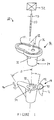
- FIG. 1 shows a kit 10 which can be used for removal of bone 12 adjacent to an implanted prosthesis 14.
- the kit 10 includes a guide 16 for cooperation with the prosthesis 14 and a tool 20.
- the tool 20 is constrainable by the guide 16 for removal of the bone 12.
- the guide 16 may include a first portion 22 of the guide 16, which is co-operable with the tool 20.
- the guide 16 may further include a second portion 24, which is co-operable with the prosthesis 14.
- first portion 22 of the guide 16 may have any shape suitable to provide for the guiding of the tool; for example, the first portion 22 may be in the form of a channel. The tool 20 may be guided within the channel 22.
- the second portion 24 of the guide 16 may have any shape or configuration capable of cooperating with the prosthesis 14.
- the second portion 24 of the guide 16 may include an external taper 26 co-operable with an internal taper 30 on the prosthesis 14.
- the channel 22 may have any suitable shape, preferably, the channel 22 has a shape so that it may guide the tool 20 in a path adjacent and slightly spaced from the prosthesis 14.
- the channel 22 will correspondingly, preferably, have a generally arcuate shape.
- the guide 16 will include a guide orientation feature 32 which, is used to angularly orient the guide 16 with respect to the prosthesis 14.
- the guide orientation feature 32 may cooperate, for example, with a prosthesis orientation feature 34 located on the prosthesis 14.
- the first portion 22 may include a first channel 36 which is adapted for cooperation with the tool 20 for removal of a first portion 40 of the bone 12 adjacent a first portion 42 of the prosthesis 14.
- the guide 16 may further include a second channel 44 adapted for cooperation with the tool 20 for removal of a second portion 46 of the bone 12 at a location adjacent a second portion 50 of the prosthesis 14.
- the tool 20 may be a hand tool that is manipulated by the surgeon
- the kit 10, as shown in FIG. 1 may further include a power source 52 to move the tool 20 with respect to the prosthesis 14 so that the tool 20 may be utilized to remove the portions 40 and 46 of the long bone 12.
- the power source 52 may be any electrical, pneumatic or hydraulic power source capable of reciprocating, rotating or other motion causing the tool 20 to move.
- the power source 52 is compatible with an operating room environment and has a capability of being sterilized or capability of avoiding contamination to the operating room.
- a purpose of the guide of the present invention is to guide or position the tool with respect to the implanted prosthesis, which is to be removed.
- the guide is designed such that the tool is caused to move in a path parallel to and very slightly spaced from the outer periphery of the prosthesis.
- the shape of the prosthesis may very widely depending on the size of the patient, the particular anatomical joint, and the manufacturer and type of prosthesis.
- a guide that is customized for a particular size and shape of the prosthesis.
- Such a guide can be designed to assure that the tool path width is minimized and that the tool is accurately positioned in a minimal apart space relationship from the prosthesis to be removed such that a minimal amount of the patients bone is sacrificed in the removal of the prosthesis.
- the guide 16 as shown in FIGS. 1 through 5, is designed to remove the proximal portion of a total hip system sold by DePuy Orthopaedics Inc under the trade mark S-ROM.
- This total hip system includes a sleeve which is a separate component from the remainder of the total hip system and which sleeve may be separately removed from the patient during revision total joint arthroplasty.
- the guide 16, as shown in FIGS. 1 through 4 is particularly well suited for the removal of the sleeve of the DePuy S-ROM total hip system.
- a femur portion or hip stem 54 is shown as a part of an artificial hip joint.
- the hip stem 54 includes a stem 56, which is attached to arm or neck 60 and ball or head 62.
- Stem 56, arm 60 and ball 62 can be constructed in a variety of ways known to the prior art. Particularly, preferred constructions of these components are disclosed in US-3820167, US-3943576, US-3996625 and US-4077070.
- Femur portion 54 also includes collar 14.
- the collar 14 includes a body 64 having outer surfaces 66.
- the outer surfaces may be coated with a material, which provides for bony ingrowth.
- One such coating is marketed by DePuy Orthopaedics, Inc under the trade mark POROCOAT. This coating is more fully disclosed in US-3855638.
- the collar 14 also includes walled aperture 70 for receiving the stem 56.
- the walls of aperture 70 taper inwardly from the top to the bottom of the collar 14 and mate with a complimentary taper on the outside of stem 56. The slopes of these tapers are chosen so that the stem and collar lock together as the stem is pushed into the collar.
- the stem is provided with pins 72, which are received in recesses or prosthesis orientation features 34, formed in the collar 14. The pins in recesses prevent rotation of the stem 56 within aperture 70.
- Outer surface 66 of collar 14 is contoured to mate with inner surfaces 74 of the hard bone portion 76 of bone 12. That is, outer surface 66 is given a shape such that, when collar 14 is implanted in a suitably prepared bone, e.g., the upper part of the femur for the hip prosthesis, a substantial fraction of the hard bones inner surface 74 is in close proximity to or in contact with the prosthesis' outer surface 66.
- the sleeve 14 includes the body 64 with outer periphery 66, which closely conforms to inner surface 74 of the cortical bone 76 of the long bone 12.
- the body 64 includes a first portion 42 at which outer surface 66 has a generally frusto-conical shape.
- the second portion 50 of the prosthesis 14 has a shape, which is a generally wedge shaped having opposed generally parallel faces 80 connected to each other by curved portions 82.
- the frustoconical first portion 42 may be defined by angle ⁇ extending from axis 84 to outer surface 66 of the first portion 42.
- the wedge shaped second portion 50 of the prosthesis sleeve 14 may be defined by angle ⁇ from the sleeve centreline 84 to the curved portion 82 of the outer surface 66 of the second portion 50 of the prosthesis 14.
- the prosthesis orientation feature 34 may be in the form of opposed first recess 86 and second recess 90.
- the recesses 86 and 90 include opposed walls 92 and an arcuate portion 94.
- the guide 16 includes the second portion 24 which mates and cooperates with internal taper 30 of the aperture 70 of the sleeve 14.
- the second portion 24 includes an external taper, which preferably mates with internal taper 30 of the sleeve 14.
- the second portion 24 preferably includes a guide orientation feature 32 in the form, for example, a protrusion which mates with stem alignment feature or recess 34.
- the guide orientation feature may have any suitable shape and may, for example, have an external periphery which closely conforms to the periphery of the recess 34.
- the guide 16 may utilize a single channel, or, as shown in FIG. 3, a plurality of channels 22 may be used.
- a first channel 36 may be positioned in first portion 96 of plate portion 97 of the guide 16.
- a second channel 44 may be positioned in second portion 98 of the plate portion 97 of the guide 16.
- the first portion 96 of the plate portion 97 of the guide 16 corresponds to the first portion 42 of the sleeve 14, and the second portion 98 of the plate portion 97 of the guide 16 corresponds to the second portion 50 of the sleeve 14.
- the first channel 36 and the second channel 44 have a channel with SW, which is sized for rotating fit with the tool diameter TD of the tool 20.
- the slot with SW of the channels 36 and 44 are sized slightly larger than the tool diameter TD of the tool 20 so that tool 20 may provide an accurate cut of the bone 12.
- the first channel 36 preferably forms an angle ⁇ with prosthesis axis 84 which angle ⁇ is preferably the same as angle ⁇ of the outer surface 66 of the body 64 of the sleeve 14, so that a minimal amount of bone is removed by the guide 16.
- the second channel 44 forms an angle ⁇ with the prosthesis centreline 84 and the angle 84 is preferably is the same as angle ⁇ of the outer surface 66 of the body 64 in the second portion 50 of the sleeve 14. It should be appreciated that the angle ⁇ and the angle ⁇ are not a constant angle, but vary depending on the portion of outer surface 66 of the sleeve 14.
- ⁇ is different in the portion of the outer surface 66 of the sleeve than that of the faces 80 from that of ⁇ in the arcuate portions 82 of the second portion 50 of the sleeve 14.
- the angles ⁇ and ⁇ of the sleeve 14 and the guide 16 are equal at the corresponding positions along the sleeve 14 and the guide 16.
- the plate portion 97 of the guide 16 has a thickness PT sufficient to provide for strength to control the location of the tool 20.
- the guide 16 is made of a suitable durable material, for example a metal, for example tool steel or any material that may be sterilized using commercially available sterilization equipment.
- the first channel 36 and the second channel 44 are spaced from each other by, for example, lands 99.
- the plate portion 97 of the guide 16 may include a construction and removal hole 93, which is preferably positioned concentric with prosthesis centreline 84 to provide for easy removal of the guide 16 after the cuts have been made by the tool 20.
- the construction and removal hole 93 may include internal threads not shown which may be compatible with threads (not shown) in a slap hammer type device (not shown).
- the hip stem 54 is shown with the sleeve 14 installed and the hip stem positioned in long bone 14. As can be shown by FIG. 6, the hip stem 54, when installed, may result in the removal of a large portion cancellous bone 91 within the long bone 12. A portion of the cancellous bone 91 may still remain.
- the tool must remove bone from between outer surface 66 of the sleeve 14 and outer periphery 89 of the cortical bone 76 of the long bone 12. As bone thickness BT between the outer surface 66 of the sleeve 14 and outer periphery 89 of the cortical bone 76 becomes smaller, the corresponding tool required to remove the prosthesis should be smaller.
- the guide 16 is shown positioned on sleeve 14 with the sleeve 14 in position in long bone 12.
- the tool 20 has a tool diameter TD to provide for a portion of the long bone 12 to remain after the removal of the sleeve 14 requires that the tool diameter TD be considerably less than the bone thickness BT between the sleeve 14 and the cortical bone 76.
- the tool diameter TD must be considerably smaller than the bone thickness BT. For example, and as shown in FIG.
- the second channel 44 of the guide 16 forms an angle ⁇ with the centreline 84 of the sleeve 14 such that the tool 20 is very closely spaced from both the distal and proximal ends of the sleeve 14 to minimize the removal of bone from the long bone 12.
- the sleeve 14 may be available in a variety of sizes.
- a particular sized guide 16 preferably, is uniquely designed to be compatible with that particular sleeve.
- the channels for the guide will be correspondingly designed to closely conform with the outer periphery of the particularly sized sleeve.
- Such series of guides 16 will provide for a minimal bone removal regardless of the size of the sleeve.
- the tool 20 may have any suitable size and shape; but preferably, as previously mentioned, the tool 20 preferably has a thickness or diameter as small as practically possible to minimize the bone removed.
- the tool 20 includes a shank 102 as well as a cutting surface 104 extending from an end of the shank 102.
- the tool 20 may any suitable shape and may, as shown in FIG. 4, have a general elongated cylindrical shape and may be designed for rotational operation or, it should be appreciated that the tool 20 may be adapted for oscillating operation and may be in the form of a generally planer blade.
- the tool 20 may be made of any suitable, durable material and may, for example, be made of a metal, for example an alloy steel, for example tool steel.
- the cutting surface 104 may be integral with the shank 102 or be made of a separate component, and for example, a different material, such as carbide.
- the tool 20 should be made of a material that is sterilizable, for example, a metal.
- the tool 20 may be caused to move by the manual operation by the surgeon or may, as shown in FIG. 4, be connected to a power source 52, for example, a rotational power source which may be either electrical, pneumatic, or hydraulic.
- a power source 52 for example, a rotational power source which may be either electrical, pneumatic, or hydraulic.
- the power source 52 is suitable for use in an operating room. Such power sources are readily available.
- the method includes a first step 110 of providing a guide defining an opening in the guide.
- the method further includes a second step 112 of placing the guide in cooperation with the prosthesis.
- the method includes a third step 116 of providing a tool adapted for cooperation with the opening.
- the method also includes a fourth step 116 of inserting the tool at least partially within the opening.
- the method includes a fifth step 112 of causing the tool to move relative to the prosthesis.
- the method also includes a sixth step 122 of advancing the tool within the opening at least partially around the periphery of the prosthesis, and a seventh step 124 of extracting the prosthesis from the patient.
Abstract
Description
- The present invention relates generally to the field of orthopaedics, and more particularly, to an implant for use in arthroplasty.
- Joint replacement surgery is quite common and it enables many individuals to function properly when they otherwise would not be possible to do so. Such patients of joint replacement surgery typically suffer from osteoarthritis or rheumatoid arthritis. Artificial joints usually comprise metallic, ceramic and/or plastic components that are fixed to existing bone.
- Such joint replacement surgery is otherwise known as total joint arthroplasty. Total joint arthroplasty is a well-known surgical procedure by which a diseased and/or damaged joint is replaced with a prosthetic joint. In a typical total joint arthroplasty, the ends or distal portions of the bone adjacent the joint are resected or a portion of the distal part of the bone is removed and the artificial joint is secured thereto.
- For many patients suffering from osteoarthritis or rheumatoid arthritis, the procedure of total joint arthroplasty results in a prosthetic joint, which serves the patient through his or her entire life. Unfortunately, for a variety of reasons, some patients having total joint arthroplasty are not as fortunate, and the prosthetic joint must be replaced. Such a procedure to replace a prosthetic joint with a replacement prosthetic joint is called revision total joint arthroplasty. For such replacement surgery, the original or primary implant must be removed from the body or severed from the bone.
- Proper implantation of an implant during total joint arthroplasty frequently suggests that the joint be firmly secured to the adjoining bone. For example, when utilizing bone cement to secure the original prosthetic joint, pressure is applied when utilizing the cement to cause the cement to interdigitate or move somewhat in to the cancellous bone around the joint.
- Alternatively, when a prosthetic joint is utilized without bone cement, often the prosthetic joint includes an outer porous coating, which provides over time for bony ingrowth within the porous portion of the prosthesis. Whether the implant is secured with interdigitated cement or bony ingrowth, the removal of the prosthesis from the bone may be quite difficult. Typically, to remove the prosthesis, tools, for example, in the form of hand tools such as Moreland instruments or Dremel type-cutting instruments are used.
- These cutting instruments are utilized by the surgeon in a free hand procedure in which the tools are manually moved near the periphery of the prosthesis until the prosthesis and the bone are separated from each other. Since this procedure is done manually and freehand with no additional tools to assist in the placement and movement of the hand tools around the bone, the result is often that excess bone is removed from the implant. Generally, good surgical procedure requires and suggests that only the minimal amount of bone be removed from the patient. Furthermore, to implant replacement prosthesis, bone must remain to secure the replacement prosthesis to the bone.
- A need does exist for improved method and instrumentation to assist in the removal of a joint implant which provides for more accurate placement of the tools during the cutting procedure, and that provides for a procedure that also may be less time consuming than the current manual freehand approach.
- The present invention is directed to a revision cutting guide and method, which is utilized with a cutting tool to create a precise resection of bone adjacent to the existing prosthesis. The cutting guide provides for an accurate cut both in the outlined shape and the proximity of the cut to the current implant. The tool is so guided such that the cuts are quite accurate and may be made quite rapidly. Therefore, a minimum amount of material is removed and the time to perform the revision surgery is minimized.
- According to one embodiment of the present invention, a kit is provided for removal of bone adjacent to an implanted prosthesis. The kit includes a guide for cooperation with the prosthesis and a tool. The tool is constrainable by the guide for removal of the bone.
- According to another embodiment of the present invention, a guide is provided for guiding a tool for use in removal of bone adjacent to a prosthesis. The guide includes a first portion thereof cooperable with the tool and a second portion. The second portion is co-operable with the prosthesis.
- According to yet another embodiment of the present invention, a tool adapted for use with a guide for removal of bone adjacent to an implanted prosthesis is provided. The tool is constrainable by the guide for removal of the bone.
- According to a further embodiment of the present invention, there is provided a method for removing an implanted prosthesis to prepare a patient for total joint revision arthroplasty. The method includes the steps of providing a guide defining an opening therein, placing the guide in cooperation with the prosthesis, providing a tool adapted for cooperation with the opening, inserting the tool at least partially within the opening, causing the tool to move relatively to the prosthesis, advancing the tool within the opening at least partially around the periphery of the prosthesis, and extracting the prosthesis from the patient.
- The technical advantages of the present invention include a more accurate imprint or location of the cuts around the implanted prosthesis stem to be removed. For example, according to one aspect of the present invention, the guide includes channels positioned about the outer periphery of the guide, which conform to a path slightly outside of the outer periphery of the implant to be removed. The tool is moved about the pocket to provide for cuts outside the prosthesis that are very close to the prosthesis, well defined and accurate. Thus, the present invention provides for improved accuracy cuts and minimal removal of bone when making cuts to loosen the prosthesis for its removal.
- Another technical advantage of the present invention reduces damage to the tool caused by the tool being in contact in cutting the hardened prosthesis. For example, according to one aspect of the present invention the tool includes channels, which guide the tool in a spaced apart relationship to the prosthesis.
- Further, according to a another aspect of the present invention, the guide includes a first guide feature which cooperates with a prosthesis feature such that the guide and the prosthesis are aligned such that the movement of the tool along the channels provides for an accurate space from the prosthesis cut such that the tool does not contact the prosthesis and cause damage to the tool.
- A further technical advantage of the present invention includes reduced damage and minimal removal of bone during the removal cuts performed by the tool. For example, according to one aspect of the present invention, the guide includes channels which may be aligned with the periphery of the tool and the guide, has a feature which may be aligned with a feature on the prosthesis such that if the tool is moved about the channels of the guide the cutting tool accurately cuts a minimal path adjacent to the prosthesis such that the amount of bone loss during prosthesis removal is minimized.
- The technical advantages of the present invention further include the ability to form the removal cuts to remove the implant in a much greater speed. For example, according to one aspect of the present invention, the guide includes a plurality of spaced-apart channels which occupy most of the cross sectional area of the guide such that when the guide, in cooperation with the tool, is used to form the pockets for the implant, only a quick and simple use of an osteotome to remove the small portions of the material remaining after the utilization of the tool and the guide can be quickly accomplished. Therefore, with the rapid use of the guide and the tool, as well as, a minimal use of the osteotome, the pocket may be prepared very quickly and accurately.
- Embodiments of the invention will now be described by way of example with reference to the accompanying drawings, in which:
- FIG. 1 is an exploded perspective view of a kit according to the present invention, including a guide and tool is shown in cooperation with a femoral component of a hip prosthesis in accordance with an embodiment of the present invention;
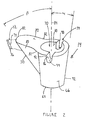
- FIG. 2 is an enlarged perspective view of a femoral component of a hip prosthesis with which the kit of FIG. 1 may be used;
- FIG. 3 is an enlarged perspective view of the guide of FIG. 1 ; and
- FIG. 4 is an enlarged perspective view of the tool of FIG. 1.
- FIG. 5 is a perspective view of a femoral hip stem prosthesis assembly with which the kit of FIG. 1 may be used;
- FIG. 6 is a plan view partially in cross section of the femoral hip stem prosthesis assembly of FIG. 5;
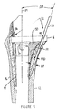
- FIG. 7 is a plan view, partially in cross section, of the femoral hip stem prosthesis assembly of FIG. 6 installed in a femur with the stem removed the guide of FIG. 3 installed; and
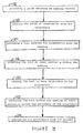
- FIG. 8 is a process flow chart for a method of removing an implanted prosthesis according to an embodiment of the present invention.
-
- Referring to the drawings, FIG. 1 shows a
kit 10 which can be used for removal ofbone 12 adjacent to an implantedprosthesis 14. Thekit 10 includes aguide 16 for cooperation with theprosthesis 14 and atool 20. Thetool 20 is constrainable by theguide 16 for removal of thebone 12. Theguide 16 may include afirst portion 22 of theguide 16, which is co-operable with thetool 20. Theguide 16 may further include asecond portion 24, which is co-operable with theprosthesis 14. - While it should be appreciated with the first portion, 22 of the
guide 16 may have any shape suitable to provide for the guiding of the tool; for example, thefirst portion 22 may be in the form of a channel. Thetool 20 may be guided within thechannel 22. - The
second portion 24 of theguide 16 may have any shape or configuration capable of cooperating with theprosthesis 14. For example, thesecond portion 24 of theguide 16 may include anexternal taper 26 co-operable with aninternal taper 30 on theprosthesis 14. - While the
channel 22 may have any suitable shape, preferably, thechannel 22 has a shape so that it may guide thetool 20 in a path adjacent and slightly spaced from theprosthesis 14. For example, if theprosthesis 14 has a generally arcuate periphery, thechannel 22 will correspondingly, preferably, have a generally arcuate shape. - Preferably, and as shown in FIG. 1, the
guide 16 will include aguide orientation feature 32 which, is used to angularly orient theguide 16 with respect to theprosthesis 14. Theguide orientation feature 32 may cooperate, for example, with aprosthesis orientation feature 34 located on theprosthesis 14. - While it should be appreciated that the present invention may be practised with a
solitary channel 22, as shown in FIG. 1, thefirst portion 22 may include afirst channel 36 which is adapted for cooperation with thetool 20 for removal of afirst portion 40 of thebone 12 adjacent afirst portion 42 of theprosthesis 14. - The
guide 16 may further include asecond channel 44 adapted for cooperation with thetool 20 for removal of asecond portion 46 of thebone 12 at a location adjacent asecond portion 50 of theprosthesis 14. - While it should be appreciated that the
tool 20 may be a hand tool that is manipulated by the surgeon, thekit 10, as shown in FIG. 1, may further include apower source 52 to move thetool 20 with respect to theprosthesis 14 so that thetool 20 may be utilized to remove theportions long bone 12. Thepower source 52 may be any electrical, pneumatic or hydraulic power source capable of reciprocating, rotating or other motion causing thetool 20 to move. Preferably, thepower source 52 is compatible with an operating room environment and has a capability of being sterilized or capability of avoiding contamination to the operating room. - A purpose of the guide of the present invention is to guide or position the tool with respect to the implanted prosthesis, which is to be removed. Preferably, the guide is designed such that the tool is caused to move in a path parallel to and very slightly spaced from the outer periphery of the prosthesis. The shape of the prosthesis may very widely depending on the size of the patient, the particular anatomical joint, and the manufacturer and type of prosthesis.
- Differences in patient anatomy and physical condition, as well as differences in surgical techniques and surgeon preferences, necessitate prostheses having a wide variety of shapes and sizes. Consequently, it may be desirable to have a guide that is customized for a particular size and shape of the prosthesis. Such a guide can be designed to assure that the tool path width is minimized and that the tool is accurately positioned in a minimal apart space relationship from the prosthesis to be removed such that a minimal amount of the patients bone is sacrificed in the removal of the prosthesis.
- The
guide 16, as shown in FIGS. 1 through 5, is designed to remove the proximal portion of a total hip system sold by DePuy Orthopaedics Inc under the trade mark S-ROM. This total hip system includes a sleeve which is a separate component from the remainder of the total hip system and which sleeve may be separately removed from the patient during revision total joint arthroplasty. Theguide 16, as shown in FIGS. 1 through 4, is particularly well suited for the removal of the sleeve of the DePuy S-ROM total hip system. - Referring now to FIG. 5, a femur portion or hip stem 54 is shown as a part of an artificial hip joint. The hip stem 54 includes a
stem 56, which is attached to arm orneck 60 and ball orhead 62.Stem 56,arm 60 andball 62 can be constructed in a variety of ways known to the prior art. Particularly, preferred constructions of these components are disclosed in US-3820167, US-3943576, US-3996625 and US-4077070. -
Femur portion 54 also includescollar 14. Thecollar 14 includes abody 64 havingouter surfaces 66. The outer surfaces may be coated with a material, which provides for bony ingrowth. One such coating is marketed by DePuy Orthopaedics, Inc under the trade mark POROCOAT. This coating is more fully disclosed in US-3855638. - The
collar 14 also includeswalled aperture 70 for receiving thestem 56. The walls ofaperture 70 taper inwardly from the top to the bottom of thecollar 14 and mate with a complimentary taper on the outside ofstem 56. The slopes of these tapers are chosen so that the stem and collar lock together as the stem is pushed into the collar. To further securestem 56 tocollar 14, the stem is provided withpins 72, which are received in recesses or prosthesis orientation features 34, formed in thecollar 14. The pins in recesses prevent rotation of thestem 56 withinaperture 70. -
Outer surface 66 ofcollar 14 is contoured to mate withinner surfaces 74 of thehard bone portion 76 ofbone 12. That is,outer surface 66 is given a shape such that, whencollar 14 is implanted in a suitably prepared bone, e.g., the upper part of the femur for the hip prosthesis, a substantial fraction of the hard bonesinner surface 74 is in close proximity to or in contact with the prosthesis'outer surface 66. - Referring now to FIG. 2, the collar or
sleeve 14 is shown in greater detail. Thesleeve 14 includes thebody 64 withouter periphery 66, which closely conforms toinner surface 74 of thecortical bone 76 of thelong bone 12. - The
body 64, as shown in FIG. 2, includes afirst portion 42 at whichouter surface 66 has a generally frusto-conical shape. Thesecond portion 50 of theprosthesis 14 has a shape, which is a generally wedge shaped having opposed generally parallel faces 80 connected to each other bycurved portions 82. The frustoconicalfirst portion 42 may be defined by angle α extending fromaxis 84 toouter surface 66 of thefirst portion 42. - The wedge shaped
second portion 50 of theprosthesis sleeve 14 may be defined by angle β from thesleeve centreline 84 to thecurved portion 82 of theouter surface 66 of thesecond portion 50 of theprosthesis 14. - As shown in FIG. 2, the
prosthesis orientation feature 34 may be in the form of opposed first recess 86 andsecond recess 90. Therecesses 86 and 90 include opposedwalls 92 and anarcuate portion 94. - Referring now to FIG. 3, the
guide 16 is shown in greater detail. Theguide 16 includes thesecond portion 24 which mates and cooperates withinternal taper 30 of theaperture 70 of thesleeve 14. Thesecond portion 24 includes an external taper, which preferably mates withinternal taper 30 of thesleeve 14. Thesecond portion 24 preferably includes aguide orientation feature 32 in the form, for example, a protrusion which mates with stem alignment feature orrecess 34. The guide orientation feature may have any suitable shape and may, for example, have an external periphery which closely conforms to the periphery of therecess 34. - The
guide 16 may utilize a single channel, or, as shown in FIG. 3, a plurality ofchannels 22 may be used. For example, and as shown in FIG. 3, afirst channel 36 may be positioned infirst portion 96 ofplate portion 97 of theguide 16. Further, asecond channel 44 may be positioned insecond portion 98 of theplate portion 97 of theguide 16. Thefirst portion 96 of theplate portion 97 of theguide 16 corresponds to thefirst portion 42 of thesleeve 14, and thesecond portion 98 of theplate portion 97 of theguide 16 corresponds to thesecond portion 50 of thesleeve 14. - The
first channel 36 and thesecond channel 44 have a channel with SW, which is sized for rotating fit with the tool diameter TD of thetool 20. The slot with SW of thechannels tool 20 so thattool 20 may provide an accurate cut of thebone 12. - The
first channel 36 preferably forms an angle αα withprosthesis axis 84 which angle αα is preferably the same as angle α of theouter surface 66 of thebody 64 of thesleeve 14, so that a minimal amount of bone is removed by theguide 16. Similarly, thesecond channel 44 forms an angle ββ with theprosthesis centreline 84 and theangle 84 is preferably is the same as angle β of theouter surface 66 of thebody 64 in thesecond portion 50 of thesleeve 14. It should be appreciated that the angle ββ and the angle β are not a constant angle, but vary depending on the portion ofouter surface 66 of thesleeve 14. For example, β is different in the portion of theouter surface 66 of the sleeve than that of thefaces 80 from that of β in thearcuate portions 82 of thesecond portion 50 of thesleeve 14. Preferably, however, the angles β and ββ of thesleeve 14 and theguide 16 are equal at the corresponding positions along thesleeve 14 and theguide 16. - The
plate portion 97 of theguide 16 has a thickness PT sufficient to provide for strength to control the location of thetool 20. Theguide 16 is made of a suitable durable material, for example a metal, for example tool steel or any material that may be sterilized using commercially available sterilization equipment. - To provide for structural integrity of the
plate portion 97, thefirst channel 36 and thesecond channel 44 are spaced from each other by, for example, lands 99. Also, optionally, theplate portion 97 of theguide 16 may include a construction andremoval hole 93, which is preferably positioned concentric withprosthesis centreline 84 to provide for easy removal of theguide 16 after the cuts have been made by thetool 20. - Referring again to FIG. 3, the construction and
removal hole 93 may include internal threads not shown which may be compatible with threads (not shown) in a slap hammer type device (not shown). - Referring now to FIG. 6, the
hip stem 54 is shown with thesleeve 14 installed and the hip stem positioned inlong bone 14. As can be shown by FIG. 6, thehip stem 54, when installed, may result in the removal of a large portioncancellous bone 91 within thelong bone 12. A portion of thecancellous bone 91 may still remain. - It should be appreciated that the tool must remove bone from between
outer surface 66 of thesleeve 14 andouter periphery 89 of thecortical bone 76 of thelong bone 12. As bone thickness BT between theouter surface 66 of thesleeve 14 andouter periphery 89 of thecortical bone 76 becomes smaller, the corresponding tool required to remove the prosthesis should be smaller. - Referring now to FIG. 7, the
guide 16 is shown positioned onsleeve 14 with thesleeve 14 in position inlong bone 12. As can be seen in FIG. 7, thetool 20 has a tool diameter TD to provide for a portion of thelong bone 12 to remain after the removal of thesleeve 14 requires that the tool diameter TD be considerably less than the bone thickness BT between thesleeve 14 and thecortical bone 76. In fact, because of the arcuate nature of the long bone, particularly adjacent,second portion 50 of theprosthesis sleeve 14 the tool diameter TD must be considerably smaller than the bone thickness BT. For example, and as shown in FIG. 7, thesecond channel 44 of theguide 16 forms an angle ββ with thecentreline 84 of thesleeve 14 such that thetool 20 is very closely spaced from both the distal and proximal ends of thesleeve 14 to minimize the removal of bone from thelong bone 12. - Referring again to FIG. 7, it should be appreciated that to accommodate different sizes of the patient and the correspondingly different sizes of the
long bone 12, thesleeve 14 may be available in a variety of sizes. For each particular size ofsleeve 14, a particularsized guide 16, preferably, is uniquely designed to be compatible with that particular sleeve. Correspondingly, the channels for the guide will be correspondingly designed to closely conform with the outer periphery of the particularly sized sleeve. Such series ofguides 16 will provide for a minimal bone removal regardless of the size of the sleeve. - Referring now to FIG. 4, the
tool 20 is shown in greater detail. Thetool 20 may have any suitable size and shape; but preferably, as previously mentioned, thetool 20 preferably has a thickness or diameter as small as practically possible to minimize the bone removed. Thetool 20 includes ashank 102 as well as a cuttingsurface 104 extending from an end of theshank 102. - The
tool 20 may any suitable shape and may, as shown in FIG. 4, have a general elongated cylindrical shape and may be designed for rotational operation or, it should be appreciated that thetool 20 may be adapted for oscillating operation and may be in the form of a generally planer blade. - The
tool 20 may be made of any suitable, durable material and may, for example, be made of a metal, for example an alloy steel, for example tool steel. The cuttingsurface 104 may be integral with theshank 102 or be made of a separate component, and for example, a different material, such as carbide. - It should be appreciated that the
tool 20 should be made of a material that is sterilizable, for example, a metal. - The
tool 20 may be caused to move by the manual operation by the surgeon or may, as shown in FIG. 4, be connected to apower source 52, for example, a rotational power source which may be either electrical, pneumatic, or hydraulic. Preferably, thepower source 52 is suitable for use in an operating room. Such power sources are readily available. - Referring now to FIG. 8, a method for removing a prosthesis is shown. The method includes a
first step 110 of providing a guide defining an opening in the guide. The method further includes asecond step 112 of placing the guide in cooperation with the prosthesis. The method includes athird step 116 of providing a tool adapted for cooperation with the opening. The method also includes afourth step 116 of inserting the tool at least partially within the opening. - Further, the method includes a
fifth step 112 of causing the tool to move relative to the prosthesis. The method also includes asixth step 122 of advancing the tool within the opening at least partially around the periphery of the prosthesis, and aseventh step 124 of extracting the prosthesis from the patient.
Claims (17)
- A kit for removal of bone adjacent to an implanted prosthesis, said kit comprising:a guide for cooperation with the prosthesis; anda tool constrainable by said guide for removal of the bone.
- The kit of claim 1, wherein said guide comprises:a first portion thereof co-operable with said tool; anda second portion co-operable with the prosthesis. The kit of claim 2, wherein the first portion of said guide defines a channel there through, said tool guidable within the channel.
- The kit of claim 2, wherein the second portion of said guide comprises an external taper co-operable with an internal taper on the prosthesis.
- The kit of claim 3, wherein the channel has a generally arcuate shape.
- The kit of claim 2, wherein said guide comprises a guide orientation feature for cooperation with a prosthesis orientation feature on the prosthesis.
- The kit of claim 3, wherein said first mentioned channel is adapted for cooperation with the tool for removal of a first portion of bone adjacent a first portion of the prosthesis; and further comprising a second channel adapted for cooperation with the tool for removal of a second portion of bone adjacent a second portion of the prosthesis.
- The kit of claim 1, further comprising a power source to move the tool with respect to the prosthesis.
- The kit of claim 1, wherein said tool comprises one of a reciprocating tool or a rotating tool.
- A guide for guiding a tool for use in removal of bone adjacent to a prosthesis, said guide comprising: a first portion thereof co-operable with said tool; and a second portion co-operable with the prosthesis.
- The guide of claim 9, wherein the first portion of said guide defines a channel there through, the tool guidable within the channel.
- The guide of claim 9, wherein the second portion of said guide comprises an external taper co-operable with an internal taper on the prosthesis.
- The guide of claim 10, wherein the channel has a generally arcuate shape.
- The guide of claim 9, wherein said guide comprises a first orientation feature for cooperation with the orientation feature on the prosthesis.
- The guide of claim 10, wherein said first mentioned channel is adapted for cooperation with the tool for removal of a first portion of bone adjacent a first portion of the prosthesis; and further comprising a second channel adapted for cooperation with the tool for removal of a second portion of bone adjacent a second portion of the prosthesis.
- A tool adapted for use with a guide for removal of bone adjacent to an implanted prosthesis, said tool constrainable by the guide for removal of the bone.
- The tool of claim 15, wherein the tool is adapted for one of rotating operation and reciprocating operation.
- The tool of claim 16, wherein the tool is a rotating burr tool.
Applications Claiming Priority (2)
| Application Number | Priority Date | Filing Date | Title |
|---|---|---|---|
| US176934 | 2002-06-21 | ||
| US10/176,934 US7935118B2 (en) | 2002-06-21 | 2002-06-21 | Prosthesis removal cutting guide, cutting tool and method |
Publications (3)
| Publication Number | Publication Date |
|---|---|
| EP1374779A2 true EP1374779A2 (en) | 2004-01-02 |
| EP1374779A3 EP1374779A3 (en) | 2005-03-30 |
| EP1374779B1 EP1374779B1 (en) | 2008-12-31 |
Family
ID=29717851
Family Applications (1)
| Application Number | Title | Priority Date | Filing Date |
|---|---|---|---|
| EP03253925A Expired - Lifetime EP1374779B1 (en) | 2002-06-21 | 2003-06-20 | Prosthesis removal cutting guide and cutting tool |
Country Status (5)
| Country | Link |
|---|---|
| US (2) | US7935118B2 (en) |
| EP (1) | EP1374779B1 (en) |
| AT (1) | ATE418921T1 (en) |
| AU (2) | AU2003204784B2 (en) |
| DE (1) | DE60325532D1 (en) |
Families Citing this family (14)
| Publication number | Priority date | Publication date | Assignee | Title |
|---|---|---|---|---|
| US8025663B2 (en) * | 2003-12-30 | 2011-09-27 | Depuy Products, Inc. | Augments for surgical instruments |
| US7534271B2 (en) * | 2004-01-22 | 2009-05-19 | Smith + Nephew | Femoral hip prosthesis and method of implantation |
| US8273088B2 (en) * | 2005-07-08 | 2012-09-25 | Depuy Spine, Inc. | Bone removal tool |
| US8052687B2 (en) * | 2006-09-29 | 2011-11-08 | Depuy Products, Inc. | Calcar planar |
| FR2910804B1 (en) * | 2007-01-02 | 2010-03-12 | Michel Isidori | BONE GUIDING AND MODELING DEVICE FOR THE PREPARATION OF BONE SITES IN SURGERY |
| WO2009046152A1 (en) * | 2007-10-01 | 2009-04-09 | Smith & Nephew, Inc. | Modular necks for orthopaedic devices |
| FR2946861B1 (en) * | 2009-06-18 | 2012-07-27 | Jean Claude Cartillier | HIP PROSTHESIS. |
| US9265510B2 (en) * | 2012-02-06 | 2016-02-23 | Zimmer, Inc. | Cone lock quick connect mechanism |
| WO2014043093A1 (en) * | 2012-09-14 | 2014-03-20 | DePuy Synthes Products, LLC | Multihole drill sleeve with protection sleeve |
| US9603720B2 (en) * | 2013-08-26 | 2017-03-28 | Scott Kelley | Osteotome guide configured to attach to an implanted femoral component |
| US9867628B2 (en) * | 2013-11-07 | 2018-01-16 | Zimmer, Inc. | Device for extraction of prosthetic implants |
| US10182830B2 (en) * | 2016-04-05 | 2019-01-22 | Arthrology Consulting, Llc | Modular total knee arthroplasty system and method |
| WO2019213025A1 (en) * | 2018-05-02 | 2019-11-07 | MAP Medical Solutions, LLC | Joint revision surgery apparatus |
| US11191651B1 (en) | 2019-06-05 | 2021-12-07 | Rivera Surgical LLC | Implant removal tool |
Citations (6)
| Publication number | Priority date | Publication date | Assignee | Title |
|---|---|---|---|---|
| US5403321A (en) * | 1993-12-15 | 1995-04-04 | Smith & Nephew Richards Inc. | Radiolucent drill guide |
| EP0962190A2 (en) * | 1998-06-01 | 1999-12-08 | JOHNSON & JOHNSON ORTHOPAEDICS, INC. | Calcar milling guide and system |
| US6139551A (en) * | 1995-06-07 | 2000-10-31 | Sdgi Holdings, Inc. | Anterior spinal instrumentation and method for implantation and revision |
| US6179877B1 (en) * | 1992-11-20 | 2001-01-30 | Dennis W. Burke | Centering device for femoral implant and method and apparatus for implementation thereof |
| US6187012B1 (en) * | 1999-07-08 | 2001-02-13 | Medidea, Llc | Prosthetic element removal apparatus and methods |
| WO2003034955A1 (en) * | 2001-10-19 | 2003-05-01 | Biomet Merck Gmbh | Femoral prosthesis |
Family Cites Families (162)
| Publication number | Priority date | Publication date | Assignee | Title |
|---|---|---|---|---|
| US1630239A (en) | 1924-05-09 | 1927-05-24 | Roy S Binkley | Antrum burr |
| US3820167A (en) | 1968-06-18 | 1974-06-28 | K Sivash | Artificial hip joint |
| US3943576A (en) | 1971-10-14 | 1976-03-16 | Sivash Konstantin Mitrofanovic | Artificial hip joint made from two different surgical alloys |
| US4077070A (en) | 1968-06-18 | 1978-03-07 | Sivash Konstantin Mitrofanovic | Artificial hip joint |
| CA962806A (en) | 1970-06-04 | 1975-02-18 | Ontario Research Foundation | Surgical prosthetic device |
| DE2236141B2 (en) | 1972-07-22 | 1976-07-08 | Fa. Waldemar Link, 2000 Hamburg | PARTIAL DENTURE FOR A HUMAN ANKLE |
| US3835858A (en) * | 1972-09-05 | 1974-09-17 | Weck & Co Inc Edward | Surgical air drill |
| GB1446593A (en) | 1973-01-12 | 1976-08-18 | Nat Res Dev | Endoprosthetic ankle joint devices |
| FR2220235A1 (en) | 1973-03-09 | 1974-10-04 | Anvar | Arthroplastic pin prosthesis - has front feet fitting in cavities in ankle bone and rear one in calcaneum |
| US3867932A (en) | 1974-01-18 | 1975-02-25 | Donald R Huene | Assembly for inserting rigid shafts into fractured bones |
| US3872519A (en) | 1974-04-04 | 1975-03-25 | Nicholas J Giannestras | Total ankle prosthesis |
| US3886599A (en) | 1974-07-25 | 1975-06-03 | Schlein Louis Charles | Surgically implantable total ankle prosthesis |
| US3889300A (en) | 1974-08-28 | 1975-06-17 | Wright Mfg | Articulated two-part prosthesis replacing the ankle joint |
| US3996625A (en) | 1975-02-28 | 1976-12-14 | United States Surgical Corporation | Artificial hip joint with novel stem |
| US3975778A (en) | 1975-07-14 | 1976-08-24 | Newton Iii St Elmo | Total ankle arthroplasty |
| US3987500A (en) | 1976-01-28 | 1976-10-26 | Schlein Allen P | Surgically implantable total ankle prosthesis |
| US4021864A (en) | 1976-04-14 | 1977-05-10 | The Regents Of The University Of California | Ankle prosthesis |
| US4069518A (en) | 1976-08-31 | 1978-01-24 | Groth Jr Harry E | Total ankle prosthesis |
| GB1579773A (en) | 1977-07-18 | 1980-11-26 | Nat Res Dev | Endoprosthetic bone joint devices |
| US4470158A (en) | 1978-03-10 | 1984-09-11 | Biomedical Engineering Corp. | Joint endoprosthesis |
| US4952214A (en) * | 1981-08-20 | 1990-08-28 | Ohio Medical Instrument Co., Inc. | Arcuate osteotomy blade, blade guide, and cutting method |
| US5147364A (en) * | 1981-08-20 | 1992-09-15 | Ohio Medical Instrument Company | Osteotomy saw/file, cutting guide and method |
| US4551863A (en) | 1981-09-28 | 1985-11-12 | Murray William M | Femoral component and method |
| US4567885A (en) | 1981-11-03 | 1986-02-04 | Androphy Gary W | Triplanar knee resection system |
| US4450591A (en) | 1981-12-10 | 1984-05-29 | Rappaport Mark J | Internal anti-proratory plug assembly and process of installing the same |
| US4524766A (en) | 1982-01-07 | 1985-06-25 | Petersen Thomas D | Surgical knee alignment method and system |
| US4421112A (en) | 1982-05-20 | 1983-12-20 | Minnesota Mining And Manufacturing Company | Tibial osteotomy guide assembly and method |
| US4530114A (en) | 1982-07-16 | 1985-07-23 | Slobodan Tepic | Total hip joint prostheses |
| US4467801A (en) | 1983-03-09 | 1984-08-28 | Wright Manufacturing Company | Method and apparatus for shaping a proximal tibial surface |
| US4474177A (en) | 1983-03-09 | 1984-10-02 | Wright Manufacturing Company | Method and apparatus for shaping a distal femoral surface |
| FR2543821A3 (en) | 1983-04-08 | 1984-10-12 | Viladot Perice Antonio | Endo-orthesis for flat feet |
| US4672957A (en) | 1983-10-04 | 1987-06-16 | South African Inventions Development Corporation | Surgical device |
| US4846839A (en) | 1984-02-09 | 1989-07-11 | Joint Medical Products Corporation | Apparatus for affixing a prosthesis to bone |
| US4721104A (en) | 1985-12-02 | 1988-01-26 | Dow Corning Wright Corporation | Femoral surface shaping apparatus for posterior-stabilized knee implants |
| US4708139A (en) | 1986-02-24 | 1987-11-24 | Dunbar Iv William H | Arthroscopic drill guide |
| US4703751A (en) | 1986-03-27 | 1987-11-03 | Pohl Kenneth P | Method and apparatus for resecting a distal femoral surface |
| US4719908A (en) | 1986-08-15 | 1988-01-19 | Osteonics Corp. | Method and apparatus for implanting a prosthetic device |
| US4790852A (en) | 1986-09-15 | 1988-12-13 | Joint Medical Products Corporation | Sleeves for affixing artificial joints to bone |
| US4755185A (en) | 1987-01-27 | 1988-07-05 | Boehringer Mannheim Corporation | Prosthetic joint |
| US5002547A (en) | 1987-02-07 | 1991-03-26 | Pfizer Hospital Products Group, Inc. | Apparatus for knee prosthesis |
| US4885603A (en) | 1987-04-02 | 1989-12-05 | Brother Kogyo Kabushiki Kaisha | Image recording apparatus for producing glossy image medium |
| FR2615726A1 (en) | 1987-06-01 | 1988-12-02 | Landos Applic Orthopediques Fs | Prosthetic fixation element with anchoring stud |
| FR2616059A1 (en) | 1987-06-05 | 1988-12-09 | Sorem Soc Realisa Elect Mec | Apparatus for reduction and/or containment of a fractured bone |
| US4815902A (en) | 1987-07-01 | 1989-03-28 | Petersen Manufacturing Co., Inc. | Stepped fluted drill |
| US5011496A (en) | 1988-02-02 | 1991-04-30 | Joint Medical Products Corporation | Prosthetic joint |
| US4865603A (en) | 1988-02-04 | 1989-09-12 | Joint Medical Products Corporation | Metallic prosthetic devices having micro-textured outer surfaces |
| GB8802671D0 (en) | 1988-02-05 | 1988-03-02 | Goodfellow J W | Orthopaedic joint components tools & methods |
| US4979949A (en) | 1988-04-26 | 1990-12-25 | The Board Of Regents Of The University Of Washington | Robot-aided system for surgery |
| US5484437A (en) | 1988-06-13 | 1996-01-16 | Michelson; Gary K. | Apparatus and method of inserting spinal implants |
| US4892093A (en) | 1988-10-28 | 1990-01-09 | Osteonics Corp. | Femoral cutting guide |
| US4968316A (en) | 1988-12-12 | 1990-11-06 | Hergenroeder Patrick T | Arthroscopic ankle joint distraction method |
| US4926847A (en) * | 1988-12-27 | 1990-05-22 | Johnson & Johnson Orthopaedics, Inc. | Surgical cutting block |
| US4952213A (en) | 1989-02-03 | 1990-08-28 | Boehringer Mannheim Corporation | Tibial cutting guide |
| US5234433A (en) | 1989-09-26 | 1993-08-10 | Kirschner Medical Corporation | Method and instrumentation for unicompartmental total knee arthroplasty |
| US5122144A (en) | 1989-09-26 | 1992-06-16 | Kirschner Medical Corporation | Method and instrumentation for unicompartmental total knee arthroplasty |
| US5167619A (en) | 1989-11-17 | 1992-12-01 | Sonokineticss Group | Apparatus and method for removal of cement from bone cavities |
| SE8904036L (en) | 1989-11-29 | 1991-05-30 | Volvo Ab | LED PROTES, IN PARTICULAR, FOOT LEADER |
| US5171244A (en) | 1990-01-08 | 1992-12-15 | Caspari Richard B | Methods and apparatus for arthroscopic prosthetic knee replacement |
| US5246444A (en) | 1990-01-08 | 1993-09-21 | Schreiber Saul N | Osteotomy device and method |
| US5035699A (en) | 1990-01-09 | 1991-07-30 | Dow Corning Wright | Patella track cutter and guide |
| US5163940A (en) | 1991-03-04 | 1992-11-17 | American Cyanamid Company | Surgical drill guide for tibia |
| US5100408A (en) | 1991-03-07 | 1992-03-31 | Smith & Nephew Richards Inc. | Femoral instrumentation for long stem surgery |
| US5053037A (en) | 1991-03-07 | 1991-10-01 | Smith & Nephew Richards Inc. | Femoral instrumentation for long stem surgery |
| FR2676917B1 (en) | 1991-05-29 | 1993-08-27 | Omci | ANKLE PROSTHESIS. |
| US5449360A (en) | 1991-08-23 | 1995-09-12 | Schreiber; Saul N. | Osteotomy device and method |
| FR2680968B1 (en) | 1991-09-05 | 1993-12-17 | Procom Sa | IMPLANT FOR SUB-ASTRAGALIAN ARTHRORISA. |
| FR2684291B1 (en) | 1991-12-03 | 1994-03-04 | Ysebaert | ANKLE PROSTHESIS. |
| US5344423A (en) | 1992-02-06 | 1994-09-06 | Zimmer, Inc. | Apparatus and method for milling bone |
| GB9202561D0 (en) | 1992-02-07 | 1992-03-25 | Howmedica | Orthopaedic instrument |
| US5520695A (en) | 1992-02-14 | 1996-05-28 | Johnson & Johnson Professional, Inc. | Instruments for use in knee replacement surgery |
| IT228979Y1 (en) | 1992-03-09 | 1998-06-05 | Giannini Sandro | BIODEGRADABLE PROSTHESIS FOR READY FOOT CORRECTION. |
| US5257995A (en) * | 1992-03-13 | 1993-11-02 | Midas Rex Pneumatic Tools, Inc. | Apparatus for removing a prosthesis from a bone |
| US5290291A (en) * | 1992-03-16 | 1994-03-01 | Hall Surgical, Division Of Zimmer, Inc. | Method for implant removal |
| US5295992A (en) | 1992-03-16 | 1994-03-22 | Othy, Inc. | Patella cutting system |
| US5326365A (en) | 1992-04-10 | 1994-07-05 | Alvine Franklin G | Ankle implant |
| US5207712A (en) | 1992-05-07 | 1993-05-04 | Michael Cohen | Absorbable joint implants for the lesser digits and metatarsal phalangeal joints in the surgical correction of the foot |
| US5190547A (en) | 1992-05-15 | 1993-03-02 | Midas Rex Pneumatic Tools, Inc. | Replicator for resecting bone to match a pattern |
| US5342368A (en) | 1992-07-08 | 1994-08-30 | Petersen Thomas D | Intramedullary universal proximal tibial resector guide |
| CA2144173C (en) | 1992-09-09 | 2003-08-26 | Charles A. Rockwood | Bone cutting apparatus and method |
| US5312411A (en) | 1992-10-27 | 1994-05-17 | Smith & Nephew Richards, Inc. | Uni-compartmental femoral knee instruments and prosthesis |
| WO1994012123A1 (en) | 1992-11-20 | 1994-06-09 | Burke Dennis W | Improved femoral implant collar and installation apparatus |
| US5409489A (en) | 1993-01-12 | 1995-04-25 | Sioufi; Georges | Surgical instrument for cone-shaped sub-trochanteric rotational osteotomy |
| FR2700462B1 (en) | 1993-01-19 | 1995-04-21 | Medimplant | Apparatus for implanting a joint prosthesis. |
| US5312412A (en) | 1993-02-03 | 1994-05-17 | Whipple Terry L | Fixation alignment guide for surgical use |
| JP3672330B2 (en) * | 1993-04-05 | 2005-07-20 | トヨタ自動車株式会社 | Damping structure |
| US5474559A (en) * | 1993-07-06 | 1995-12-12 | Zimmer, Inc. | Femoral milling instrumentation for use in total knee arthroplasty with optional cutting guide attachment |
| US5364402A (en) | 1993-07-29 | 1994-11-15 | Intermedics Orthopedics, Inc. | Tibial spacer saw guide |
| JP2711802B2 (en) | 1994-02-10 | 1998-02-10 | ナカシマプロペラ株式会社 | Intramedullary nail |
| US5908424A (en) * | 1994-05-16 | 1999-06-01 | Zimmer, Inc, By Said Stalcup, Dietz, Bays And Vanlaningham | Tibial milling guide system |
| US5496324A (en) | 1994-06-20 | 1996-03-05 | Zimmer, Inc. | Proximal body milling apparatus |
| US5484446A (en) | 1994-06-27 | 1996-01-16 | Zimmer, Inc. | Alignment guide for use in orthopaedic surgery |
| USD376202S (en) * | 1994-07-11 | 1996-12-03 | Zimmer, Inc. | Orthopaedic bone cutting guide |
| US5540692A (en) | 1994-07-13 | 1996-07-30 | Midas Rex Pneumatic Tools, Inc. | Replicator for resecting bone to match a pattern |
| US5810827A (en) | 1994-09-02 | 1998-09-22 | Hudson Surgical Design, Inc. | Method and apparatus for bony material removal |
| US5755803A (en) | 1994-09-02 | 1998-05-26 | Hudson Surgical Design | Prosthetic implant |
| US5643272A (en) | 1994-09-02 | 1997-07-01 | Hudson Surgical Design, Inc. | Method and apparatus for tibial resection |
| US5534005A (en) | 1994-10-05 | 1996-07-09 | Smith & Nephew Richards, Inc. | Surgical milling system |
| US5584839A (en) | 1994-12-12 | 1996-12-17 | Gieringer; Robert E. | Intraarticular drill guide and arthroscopic methods |
| US5910143A (en) | 1994-12-16 | 1999-06-08 | Exactech, Inc. | Intramedullary alignment guide tool |
| DE19501550A1 (en) | 1995-01-19 | 1996-07-25 | Dieter Prof Dr Med Wessinghage | Bone preparing device for prosthetic implants |
| FR2730157B1 (en) | 1995-02-08 | 1997-07-04 | Bouvet Jean Claude | ANKLE PROSTHESIS |
| US5624444A (en) | 1995-02-10 | 1997-04-29 | Wixon; Richard | Femoral resection instrumentation including three-dimensional jig and method of use |
| US5683397A (en) * | 1995-02-15 | 1997-11-04 | Smith & Nephew, Inc. | Distal femoral cutting guide apparatus for use in knee joint replacement surgery |
| US5562674A (en) | 1995-02-27 | 1996-10-08 | Zimmer, Inc. | Intramedullary rod with guide member locator |
| US5593411A (en) | 1995-03-13 | 1997-01-14 | Zimmer, Inc. | Orthopaedic milling guide for milling intersecting planes |
| US5766259A (en) | 1995-03-14 | 1998-06-16 | Sammarco; Giacomo J. | Total ankle prosthesis and method |
| US5634927A (en) | 1995-07-06 | 1997-06-03 | Zimmer, Inc. | Sizing plate and drill guide assembly for orthopaedic knee instrumentation |
| US5613970A (en) | 1995-07-06 | 1997-03-25 | Zimmer, Inc. | Orthopaedic instrumentation assembly having an offset bushing |
| US5613971A (en) | 1995-08-11 | 1997-03-25 | Depuy Inc. | Ratcheting tibial and femoral guide |
| US5601563A (en) | 1995-08-25 | 1997-02-11 | Zimmer, Inc. | Orthopaedic milling template with attachable cutting guide |
| US5709689A (en) * | 1995-09-25 | 1998-01-20 | Wright Medical Technology, Inc. | Distal femur multiple resection guide |
| US5733290A (en) | 1995-12-21 | 1998-03-31 | Johnson & Johnson Professional, Inc. | Quick-release tibial alignment handle |
| US6267785B1 (en) * | 1996-02-01 | 2001-07-31 | Medidea, Llc | Apparatus for positioning a prosthetic element to achieve a desired orientation for cementation |
| US5653714A (en) | 1996-02-22 | 1997-08-05 | Zimmer, Inc. | Dual slide cutting guide |
| WO1997030648A1 (en) | 1996-02-23 | 1997-08-28 | Midwest Orthopedic Research Foundation | Device and method for distal femur cutting and prothesis measuring |
| FR2747302B1 (en) | 1996-04-11 | 1998-09-11 | Tornier Sa | ANKLE PROSTHESIS |
| US5769854A (en) | 1996-08-23 | 1998-06-23 | Osteonics Corp. | Instrument system for preparing a distal femur for a posteriorly stabilized femoral component of a knee prosthesis |
| US5725592A (en) * | 1996-10-29 | 1998-03-10 | Hayes Medical, Inc. | Modular prosthesis having neck component connected to stem component through cavity in body component |
| US5743910A (en) | 1996-11-14 | 1998-04-28 | Xomed Surgical Products, Inc. | Orthopedic prosthesis removal instrument |
| CA2225375A1 (en) * | 1996-12-23 | 1998-06-23 | Mark Manasas | Alignment guide for insertion of fluted or keyed orthopedic components |
| AU737097B2 (en) * | 1997-01-28 | 2001-08-09 | New York Society For The Relief Of The Ruptured And Crippled, Maintaining The Hospital For Special Surgery | Method and apparatus for femoral resection |
| US6090114A (en) | 1997-02-10 | 2000-07-18 | Stryker Howmedica Osteonics Corp. | Tibial plateau resection guide |
| FR2759900B1 (en) | 1997-02-26 | 1999-06-11 | Sem Sa | SYSTEM FOR REPLACING THE ANKLE JOINT |
| FR2760353B1 (en) | 1997-03-10 | 1999-07-02 | Tornier Sa | ANKLE PROSTHESIS |
| FR2760354B1 (en) | 1997-03-10 | 1999-07-02 | Tornier Sa | PARTIAL ANKLE PROSTHESIS |
| US5938665A (en) | 1997-08-25 | 1999-08-17 | Depuy Orthopaedics, Inc. | Low friction saw slot |
| US6488687B1 (en) | 1997-09-18 | 2002-12-03 | Medidea, Llc | Joint replacement method and apparatus |
| US5916220A (en) | 1998-02-02 | 1999-06-29 | Medidea, Llc | Bone cutting guide and method to accommodate different-sized implants |
| US6322564B1 (en) * | 1998-06-18 | 2001-11-27 | Depuy Orthopaedics, Inc. | Proximal alignment insertion guide and method therefor |
| DE59811929D1 (en) | 1998-06-29 | 2004-10-14 | Plus Endoprothetik Ag Rotkreuz | DEVICE FOR INSERTING A KNEE PROSTHESIS |
| US6277121B1 (en) | 1998-09-09 | 2001-08-21 | Brian D. Burkinshaw | Patella reaming system |
| US6106529A (en) | 1998-12-18 | 2000-08-22 | Johnson & Johnson Professional, Inc. | Epicondylar axis referencing drill guide |
| EP1191889B1 (en) | 1999-05-07 | 2011-07-13 | University Of Virginia Patent Foundation | System for fusing a spinal region |
| IT1310371B1 (en) | 1999-05-13 | 2002-02-13 | Ist Ortopedici Rizzoli | HUMAN ARTICULATION PROSTHESIS DEVICE, IN PARTICULAR TIBOTARSIC PARTICULATION AND RELATED METHOD OF IMPLANTATION. |
| US6368324B1 (en) * | 1999-09-24 | 2002-04-09 | Medtronic Xomed, Inc. | Powered surgical handpiece assemblies and handpiece adapter assemblies |
| US6673116B2 (en) | 1999-10-22 | 2004-01-06 | Mark A. Reiley | Intramedullary guidance systems and methods for installing ankle replacement prostheses |
| EP1223896B1 (en) | 1999-10-22 | 2006-01-11 | Mark A. Reiley | Ankle replacement system |
| FR2800601B1 (en) | 1999-11-05 | 2002-01-04 | Europ Foot Platform | ANKLE PROSTHESIS |
| AU2001241612B2 (en) | 2000-02-22 | 2005-04-07 | Warsaw Orthopedic, Inc. | Instruments and techniques for disc space preparation |
| US6342057B1 (en) | 2000-04-28 | 2002-01-29 | Synthes (Usa) | Remotely aligned surgical drill guide |
| US6520964B2 (en) | 2000-05-01 | 2003-02-18 | Std Manufacturing, Inc. | System and method for joint resurface repair |
| FR2808994B1 (en) | 2000-05-22 | 2003-03-21 | Transysteme Sarl | JOINT PROSTHESIS |
| US6361506B1 (en) | 2000-07-20 | 2002-03-26 | Sulzer Orthopedics Inc. | Incremental varus/valgus and flexion/extension measuring instrument |
| US6355045B1 (en) | 2000-12-28 | 2002-03-12 | Depuy Orthopaedics, Inc. | Method and apparatus for surgically preparing a tibia for implantation of a prosthetic implant component which has an offset stem |
| US6554838B2 (en) | 2001-05-31 | 2003-04-29 | Howmedica Osteonics Corp. | Method and apparatus for implanting a prosthetic device |
| US6482209B1 (en) | 2001-06-14 | 2002-11-19 | Gerard A. Engh | Apparatus and method for sculpting the surface of a joint |
| US20040162619A1 (en) * | 2001-08-27 | 2004-08-19 | Zimmer Technology, Inc. | Tibial augments for use with knee joint prostheses, method of implanting the tibial augment, and associated tools |
| USD473307S1 (en) | 2001-12-19 | 2003-04-15 | T. Derek V. Cooke | Knee prosthesis |
| US7090677B2 (en) * | 2002-02-12 | 2006-08-15 | Medicine Lodge, Inc. | Surgical milling instrument for shaping a bone cavity |
| ES2278028T3 (en) | 2002-03-08 | 2007-08-01 | WALDEMAR LINK GMBH & CO. KG | ENDOPROTESIS OF TIBIOTARSIAN ARTICULATION. |
| US6863691B2 (en) | 2002-04-29 | 2005-03-08 | Timothy J. Short | Ankle implant |
| US7240588B1 (en) * | 2002-06-17 | 2007-07-10 | Teleflex Medical Incorporated | Method of making a tool for extracting a broken screw |
| US7025790B2 (en) | 2002-06-27 | 2006-04-11 | Concepts In Medicine Iii, L.L.C. | Ankle joint prosthesis and its method of implantation |
| US6939380B2 (en) | 2002-12-23 | 2005-09-06 | Depuy Products, Inc. | Mobile talar component for total ankle replacement implant |
| US7011687B2 (en) | 2003-01-06 | 2006-03-14 | Depuy Products, Inc. | Ankle prosthesis with a front loading bearing and associated method |
| US7011664B2 (en) * | 2003-01-31 | 2006-03-14 | Zimmer Technology, Inc. | Resection guide alignment apparatus |
| US20040167631A1 (en) | 2003-02-21 | 2004-08-26 | Kenny Luchesi | Fixation surface for ankle prosthesis |
| US20040186585A1 (en) | 2003-03-21 | 2004-09-23 | Lawrence Feiwell | Sphere-on-sphere ankle prosthesis |
| DK1658023T3 (en) | 2003-08-27 | 2007-06-11 | Link Waldemar Gmbh Co | Ankle joint endoprosthesis |
| CA2541442C (en) | 2003-10-02 | 2011-08-30 | Concepts In Medicine Iii, Llc | Ankle joint prosthesis |
| US20050288792A1 (en) | 2004-06-23 | 2005-12-29 | Landes Mark D | Modular ankle prosthesis and associated method |
| WO2006023824A2 (en) | 2004-08-19 | 2006-03-02 | Kinetikos Medical Incorporated | Ankle prosthesis and method of curved resection |
-
2002
- 2002-06-21 US US10/176,934 patent/US7935118B2/en active Active
-
2003
- 2003-06-19 AU AU2003204784A patent/AU2003204784B2/en not_active Expired
- 2003-06-20 EP EP03253925A patent/EP1374779B1/en not_active Expired - Lifetime
- 2003-06-20 DE DE60325532T patent/DE60325532D1/en not_active Expired - Lifetime
- 2003-06-20 AT AT03253925T patent/ATE418921T1/en not_active IP Right Cessation
-
2009
- 2009-06-22 AU AU2009202497A patent/AU2009202497B2/en not_active Expired
-
2011
- 2011-05-02 US US13/098,995 patent/US8545507B2/en not_active Expired - Lifetime
Patent Citations (6)
| Publication number | Priority date | Publication date | Assignee | Title |
|---|---|---|---|---|
| US6179877B1 (en) * | 1992-11-20 | 2001-01-30 | Dennis W. Burke | Centering device for femoral implant and method and apparatus for implementation thereof |
| US5403321A (en) * | 1993-12-15 | 1995-04-04 | Smith & Nephew Richards Inc. | Radiolucent drill guide |
| US6139551A (en) * | 1995-06-07 | 2000-10-31 | Sdgi Holdings, Inc. | Anterior spinal instrumentation and method for implantation and revision |
| EP0962190A2 (en) * | 1998-06-01 | 1999-12-08 | JOHNSON & JOHNSON ORTHOPAEDICS, INC. | Calcar milling guide and system |
| US6187012B1 (en) * | 1999-07-08 | 2001-02-13 | Medidea, Llc | Prosthetic element removal apparatus and methods |
| WO2003034955A1 (en) * | 2001-10-19 | 2003-05-01 | Biomet Merck Gmbh | Femoral prosthesis |
Also Published As
| Publication number | Publication date |
|---|---|
| AU2003204784B2 (en) | 2009-04-23 |
| US20030236525A1 (en) | 2003-12-25 |
| US7935118B2 (en) | 2011-05-03 |
| AU2009202497B2 (en) | 2010-08-26 |
| AU2009202497A1 (en) | 2009-07-16 |
| ATE418921T1 (en) | 2009-01-15 |
| EP1374779B1 (en) | 2008-12-31 |
| DE60325532D1 (en) | 2009-02-12 |
| AU2003204784A1 (en) | 2004-01-22 |
| US20110208199A1 (en) | 2011-08-25 |
| US8545507B2 (en) | 2013-10-01 |
| EP1374779A3 (en) | 2005-03-30 |
Similar Documents
| Publication | Publication Date | Title |
|---|---|---|
| US8545507B2 (en) | Prosthesis removal cutting guide, cutting tool and method | |
| US11857205B2 (en) | Void filling joint prosthesis and associated instruments | |
| US11160564B2 (en) | Reciprocating rasps for use in an orthopaedic surgical procedure | |
| US9861376B2 (en) | Oscillating rasp for use in an orthopaedic surgical procedure | |
| EP1570816B1 (en) | Punch and implant | |
| US8961521B2 (en) | Reciprocating rasps for use in an orthopaedic surgical procedure | |
| US20060015112A1 (en) | Apparatus and method for preparing bone for anti-rotational implantation of an orthopedic endoprosthesis | |
| EP1396231B1 (en) | Tool for preparation of a bone cavity for arthroplasty | |
| AU2013231180B2 (en) | Method for surgically implanting a glenoid component |
Legal Events
| Date | Code | Title | Description |
|---|---|---|---|
| PUAI | Public reference made under article 153(3) epc to a published international application that has entered the european phase |
Free format text: ORIGINAL CODE: 0009012 |
|
| AK | Designated contracting states |
Kind code of ref document: A2 Designated state(s): AT BE BG CH CY CZ DE DK EE ES FI FR GB GR HU IE IT LI LU MC NL PT RO SE SI SK TR |
|
| AX | Request for extension of the european patent |
Extension state: AL LT LV MK |
|
| PUAL | Search report despatched |
Free format text: ORIGINAL CODE: 0009013 |
|
| AK | Designated contracting states |
Kind code of ref document: A3 Designated state(s): AT BE BG CH CY CZ DE DK EE ES FI FR GB GR HU IE IT LI LU MC NL PT RO SE SI SK TR |
|
| AX | Request for extension of the european patent |
Extension state: AL LT LV MK |
|
| 17P | Request for examination filed |
Effective date: 20050621 |
|
| AKX | Designation fees paid |
Designated state(s): AT BE BG CH CY CZ DE DK EE ES FI FR GB GR HU IE IT LI LU MC NL PT RO SE SI SK TR |
|
| 17Q | First examination report despatched |
Effective date: 20051006 |
|
| GRAP | Despatch of communication of intention to grant a patent |
Free format text: ORIGINAL CODE: EPIDOSNIGR1 |
|
| GRAS | Grant fee paid |
Free format text: ORIGINAL CODE: EPIDOSNIGR3 |
|
| GRAA | (expected) grant |
Free format text: ORIGINAL CODE: 0009210 |
|
| AK | Designated contracting states |
Kind code of ref document: B1 Designated state(s): AT BE BG CH CY CZ DE DK EE ES FI FR GB GR HU IE IT LI LU MC NL PT RO SE SI SK TR |
|
| REG | Reference to a national code |
Ref country code: CH Ref legal event code: NV Representative=s name: E. BLUM & CO. AG PATENT- UND MARKENANWAELTE VSP Ref country code: GB Ref legal event code: FG4D Ref country code: CH Ref legal event code: EP |
|
| REF | Corresponds to: |
Ref document number: 60325532 Country of ref document: DE Date of ref document: 20090212 Kind code of ref document: P |
|
| REG | Reference to a national code |
Ref country code: IE Ref legal event code: FG4D |
|
| PG25 | Lapsed in a contracting state [announced via postgrant information from national office to epo] |
Ref country code: SI Free format text: LAPSE BECAUSE OF FAILURE TO SUBMIT A TRANSLATION OF THE DESCRIPTION OR TO PAY THE FEE WITHIN THE PRESCRIBED TIME-LIMIT Effective date: 20081231 Ref country code: NL Free format text: LAPSE BECAUSE OF FAILURE TO SUBMIT A TRANSLATION OF THE DESCRIPTION OR TO PAY THE FEE WITHIN THE PRESCRIBED TIME-LIMIT Effective date: 20081231 Ref country code: FI Free format text: LAPSE BECAUSE OF FAILURE TO SUBMIT A TRANSLATION OF THE DESCRIPTION OR TO PAY THE FEE WITHIN THE PRESCRIBED TIME-LIMIT Effective date: 20081231 |
|
| NLV1 | Nl: lapsed or annulled due to failure to fulfill the requirements of art. 29p and 29m of the patents act | ||
| PG25 | Lapsed in a contracting state [announced via postgrant information from national office to epo] |
Ref country code: EE Free format text: LAPSE BECAUSE OF FAILURE TO SUBMIT A TRANSLATION OF THE DESCRIPTION OR TO PAY THE FEE WITHIN THE PRESCRIBED TIME-LIMIT Effective date: 20081231 Ref country code: ES Free format text: LAPSE BECAUSE OF FAILURE TO SUBMIT A TRANSLATION OF THE DESCRIPTION OR TO PAY THE FEE WITHIN THE PRESCRIBED TIME-LIMIT Effective date: 20090411 Ref country code: RO Free format text: LAPSE BECAUSE OF FAILURE TO SUBMIT A TRANSLATION OF THE DESCRIPTION OR TO PAY THE FEE WITHIN THE PRESCRIBED TIME-LIMIT Effective date: 20081231 Ref country code: BE Free format text: LAPSE BECAUSE OF FAILURE TO SUBMIT A TRANSLATION OF THE DESCRIPTION OR TO PAY THE FEE WITHIN THE PRESCRIBED TIME-LIMIT Effective date: 20081231 |
|
| PG25 | Lapsed in a contracting state [announced via postgrant information from national office to epo] |
Ref country code: AT Free format text: LAPSE BECAUSE OF FAILURE TO SUBMIT A TRANSLATION OF THE DESCRIPTION OR TO PAY THE FEE WITHIN THE PRESCRIBED TIME-LIMIT Effective date: 20081231 Ref country code: PT Free format text: LAPSE BECAUSE OF FAILURE TO SUBMIT A TRANSLATION OF THE DESCRIPTION OR TO PAY THE FEE WITHIN THE PRESCRIBED TIME-LIMIT Effective date: 20090601 Ref country code: CZ Free format text: LAPSE BECAUSE OF FAILURE TO SUBMIT A TRANSLATION OF THE DESCRIPTION OR TO PAY THE FEE WITHIN THE PRESCRIBED TIME-LIMIT Effective date: 20081231 Ref country code: SE Free format text: LAPSE BECAUSE OF FAILURE TO SUBMIT A TRANSLATION OF THE DESCRIPTION OR TO PAY THE FEE WITHIN THE PRESCRIBED TIME-LIMIT Effective date: 20090331 |
|
| PG25 | Lapsed in a contracting state [announced via postgrant information from national office to epo] |
Ref country code: SK Free format text: LAPSE BECAUSE OF FAILURE TO SUBMIT A TRANSLATION OF THE DESCRIPTION OR TO PAY THE FEE WITHIN THE PRESCRIBED TIME-LIMIT Effective date: 20081231 |
|
| PG25 | Lapsed in a contracting state [announced via postgrant information from national office to epo] |
Ref country code: DK Free format text: LAPSE BECAUSE OF FAILURE TO SUBMIT A TRANSLATION OF THE DESCRIPTION OR TO PAY THE FEE WITHIN THE PRESCRIBED TIME-LIMIT Effective date: 20081231 |
|
| PLBE | No opposition filed within time limit |
Free format text: ORIGINAL CODE: 0009261 |
|
| STAA | Information on the status of an ep patent application or granted ep patent |
Free format text: STATUS: NO OPPOSITION FILED WITHIN TIME LIMIT |
|
| 26N | No opposition filed |
Effective date: 20091001 |
|
| PG25 | Lapsed in a contracting state [announced via postgrant information from national office to epo] |
Ref country code: MC Free format text: LAPSE BECAUSE OF NON-PAYMENT OF DUE FEES Effective date: 20090630 Ref country code: BG Free format text: LAPSE BECAUSE OF FAILURE TO SUBMIT A TRANSLATION OF THE DESCRIPTION OR TO PAY THE FEE WITHIN THE PRESCRIBED TIME-LIMIT Effective date: 20090331 |
|
| PG25 | Lapsed in a contracting state [announced via postgrant information from national office to epo] |
Ref country code: GR Free format text: LAPSE BECAUSE OF FAILURE TO SUBMIT A TRANSLATION OF THE DESCRIPTION OR TO PAY THE FEE WITHIN THE PRESCRIBED TIME-LIMIT Effective date: 20090401 |
|
| PG25 | Lapsed in a contracting state [announced via postgrant information from national office to epo] |
Ref country code: IT Free format text: LAPSE BECAUSE OF FAILURE TO SUBMIT A TRANSLATION OF THE DESCRIPTION OR TO PAY THE FEE WITHIN THE PRESCRIBED TIME-LIMIT Effective date: 20081231 |
|
| PG25 | Lapsed in a contracting state [announced via postgrant information from national office to epo] |
Ref country code: LU Free format text: LAPSE BECAUSE OF NON-PAYMENT OF DUE FEES Effective date: 20090620 |
|
| PG25 | Lapsed in a contracting state [announced via postgrant information from national office to epo] |
Ref country code: HU Free format text: LAPSE BECAUSE OF FAILURE TO SUBMIT A TRANSLATION OF THE DESCRIPTION OR TO PAY THE FEE WITHIN THE PRESCRIBED TIME-LIMIT Effective date: 20090701 |
|
| PG25 | Lapsed in a contracting state [announced via postgrant information from national office to epo] |
Ref country code: TR Free format text: LAPSE BECAUSE OF FAILURE TO SUBMIT A TRANSLATION OF THE DESCRIPTION OR TO PAY THE FEE WITHIN THE PRESCRIBED TIME-LIMIT Effective date: 20081231 |
|
| PG25 | Lapsed in a contracting state [announced via postgrant information from national office to epo] |
Ref country code: CY Free format text: LAPSE BECAUSE OF FAILURE TO SUBMIT A TRANSLATION OF THE DESCRIPTION OR TO PAY THE FEE WITHIN THE PRESCRIBED TIME-LIMIT Effective date: 20081231 |
|
| REG | Reference to a national code |
Ref country code: FR Ref legal event code: PLFP Year of fee payment: 14 |
|
| REG | Reference to a national code |
Ref country code: FR Ref legal event code: PLFP Year of fee payment: 15 |
|
| REG | Reference to a national code |
Ref country code: FR Ref legal event code: PLFP Year of fee payment: 16 |
|
| PGFP | Annual fee paid to national office [announced via postgrant information from national office to epo] |
Ref country code: IE Payment date: 20220510 Year of fee payment: 20 Ref country code: GB Payment date: 20220428 Year of fee payment: 20 Ref country code: FR Payment date: 20220510 Year of fee payment: 20 Ref country code: DE Payment date: 20220505 Year of fee payment: 20 |
|
| PGFP | Annual fee paid to national office [announced via postgrant information from national office to epo] |
Ref country code: CH Payment date: 20220702 Year of fee payment: 20 |
|
| REG | Reference to a national code |
Ref country code: DE Ref legal event code: R071 Ref document number: 60325532 Country of ref document: DE |
|
| REG | Reference to a national code |
Ref country code: CH Ref legal event code: PL |
|
| REG | Reference to a national code |
Ref country code: GB Ref legal event code: PE20 Expiry date: 20230619 |
|
| REG | Reference to a national code |
Ref country code: IE Ref legal event code: MK9A |
|
| PG25 | Lapsed in a contracting state [announced via postgrant information from national office to epo] |
Ref country code: IE Free format text: LAPSE BECAUSE OF EXPIRATION OF PROTECTION Effective date: 20230620 Ref country code: GB Free format text: LAPSE BECAUSE OF EXPIRATION OF PROTECTION Effective date: 20230619 |