EP1376480A2 - Key lock device - Google Patents
Key lock device Download PDFInfo
- Publication number
- EP1376480A2 EP1376480A2 EP20030019327 EP03019327A EP1376480A2 EP 1376480 A2 EP1376480 A2 EP 1376480A2 EP 20030019327 EP20030019327 EP 20030019327 EP 03019327 A EP03019327 A EP 03019327A EP 1376480 A2 EP1376480 A2 EP 1376480A2
- Authority
- EP
- European Patent Office
- Prior art keywords
- key
- cylinder
- signal transmitting
- receiving means
- holding member
- Prior art date
- Legal status (The legal status is an assumption and is not a legal conclusion. Google has not performed a legal analysis and makes no representation as to the accuracy of the status listed.)
- Granted
Links
Images


Classifications
-
- G—PHYSICS
- G07—CHECKING-DEVICES
- G07C—TIME OR ATTENDANCE REGISTERS; REGISTERING OR INDICATING THE WORKING OF MACHINES; GENERATING RANDOM NUMBERS; VOTING OR LOTTERY APPARATUS; ARRANGEMENTS, SYSTEMS OR APPARATUS FOR CHECKING NOT PROVIDED FOR ELSEWHERE
- G07C9/00—Individual registration on entry or exit
- G07C9/00174—Electronically operated locks; Circuits therefor; Nonmechanical keys therefor, e.g. passive or active electrical keys or other data carriers without mechanical keys
- G07C9/00944—Details of construction or manufacture
-
- B—PERFORMING OPERATIONS; TRANSPORTING
- B60—VEHICLES IN GENERAL
- B60R—VEHICLES, VEHICLE FITTINGS, OR VEHICLE PARTS, NOT OTHERWISE PROVIDED FOR
- B60R25/00—Fittings or systems for preventing or indicating unauthorised use or theft of vehicles
- B60R25/01—Fittings or systems for preventing or indicating unauthorised use or theft of vehicles operating on vehicle systems or fittings, e.g. on doors, seats or windscreens
- B60R25/04—Fittings or systems for preventing or indicating unauthorised use or theft of vehicles operating on vehicle systems or fittings, e.g. on doors, seats or windscreens operating on the propulsion system, e.g. engine or drive motor
-
- B—PERFORMING OPERATIONS; TRANSPORTING
- B60—VEHICLES IN GENERAL
- B60R—VEHICLES, VEHICLE FITTINGS, OR VEHICLE PARTS, NOT OTHERWISE PROVIDED FOR
- B60R25/00—Fittings or systems for preventing or indicating unauthorised use or theft of vehicles
- B60R25/20—Means to switch the anti-theft system on or off
- B60R25/2063—Ignition switch geometry
-
- B—PERFORMING OPERATIONS; TRANSPORTING
- B60—VEHICLES IN GENERAL
- B60R—VEHICLES, VEHICLE FITTINGS, OR VEHICLE PARTS, NOT OTHERWISE PROVIDED FOR
- B60R25/00—Fittings or systems for preventing or indicating unauthorised use or theft of vehicles
- B60R25/20—Means to switch the anti-theft system on or off
- B60R25/24—Means to switch the anti-theft system on or off using electronic identifiers containing a code not memorised by the user
-
- G—PHYSICS
- G07—CHECKING-DEVICES
- G07C—TIME OR ATTENDANCE REGISTERS; REGISTERING OR INDICATING THE WORKING OF MACHINES; GENERATING RANDOM NUMBERS; VOTING OR LOTTERY APPARATUS; ARRANGEMENTS, SYSTEMS OR APPARATUS FOR CHECKING NOT PROVIDED FOR ELSEWHERE
- G07C9/00—Individual registration on entry or exit
- G07C9/00174—Electronically operated locks; Circuits therefor; Nonmechanical keys therefor, e.g. passive or active electrical keys or other data carriers without mechanical keys
- G07C2009/00579—Power supply for the keyless data carrier
- G07C2009/00603—Power supply for the keyless data carrier by power transmission from lock
-
- G—PHYSICS
- G07—CHECKING-DEVICES
- G07C—TIME OR ATTENDANCE REGISTERS; REGISTERING OR INDICATING THE WORKING OF MACHINES; GENERATING RANDOM NUMBERS; VOTING OR LOTTERY APPARATUS; ARRANGEMENTS, SYSTEMS OR APPARATUS FOR CHECKING NOT PROVIDED FOR ELSEWHERE
- G07C9/00—Individual registration on entry or exit
- G07C9/00174—Electronically operated locks; Circuits therefor; Nonmechanical keys therefor, e.g. passive or active electrical keys or other data carriers without mechanical keys
- G07C2009/00753—Electronically operated locks; Circuits therefor; Nonmechanical keys therefor, e.g. passive or active electrical keys or other data carriers without mechanical keys operated by active electrical keys
- G07C2009/00769—Electronically operated locks; Circuits therefor; Nonmechanical keys therefor, e.g. passive or active electrical keys or other data carriers without mechanical keys operated by active electrical keys with data transmission performed by wireless means
- G07C2009/00777—Electronically operated locks; Circuits therefor; Nonmechanical keys therefor, e.g. passive or active electrical keys or other data carriers without mechanical keys operated by active electrical keys with data transmission performed by wireless means by induction
-
- G—PHYSICS
- G07—CHECKING-DEVICES
- G07C—TIME OR ATTENDANCE REGISTERS; REGISTERING OR INDICATING THE WORKING OF MACHINES; GENERATING RANDOM NUMBERS; VOTING OR LOTTERY APPARATUS; ARRANGEMENTS, SYSTEMS OR APPARATUS FOR CHECKING NOT PROVIDED FOR ELSEWHERE
- G07C9/00—Individual registration on entry or exit
- G07C9/00174—Electronically operated locks; Circuits therefor; Nonmechanical keys therefor, e.g. passive or active electrical keys or other data carriers without mechanical keys
- G07C2009/00968—Electronically operated locks; Circuits therefor; Nonmechanical keys therefor, e.g. passive or active electrical keys or other data carriers without mechanical keys shape of the data carrier
- G07C2009/00984—Electronically operated locks; Circuits therefor; Nonmechanical keys therefor, e.g. passive or active electrical keys or other data carriers without mechanical keys shape of the data carrier fob
-
- Y—GENERAL TAGGING OF NEW TECHNOLOGICAL DEVELOPMENTS; GENERAL TAGGING OF CROSS-SECTIONAL TECHNOLOGIES SPANNING OVER SEVERAL SECTIONS OF THE IPC; TECHNICAL SUBJECTS COVERED BY FORMER USPC CROSS-REFERENCE ART COLLECTIONS [XRACs] AND DIGESTS
- Y10—TECHNICAL SUBJECTS COVERED BY FORMER USPC
- Y10T—TECHNICAL SUBJECTS COVERED BY FORMER US CLASSIFICATION
- Y10T70/00—Locks
- Y10T70/70—Operating mechanism
- Y10T70/7051—Using a powered device [e.g., motor]
- Y10T70/7062—Electrical type [e.g., solenoid]
- Y10T70/7068—Actuated after correct combination recognized [e.g., numerical, alphabetical, or magnet[s] pattern]
- Y10T70/7073—Including use of a key
- Y10T70/7079—Key rotated [e.g., Eurocylinder]
-
- Y—GENERAL TAGGING OF NEW TECHNOLOGICAL DEVELOPMENTS; GENERAL TAGGING OF CROSS-SECTIONAL TECHNOLOGIES SPANNING OVER SEVERAL SECTIONS OF THE IPC; TECHNICAL SUBJECTS COVERED BY FORMER USPC CROSS-REFERENCE ART COLLECTIONS [XRACs] AND DIGESTS
- Y10—TECHNICAL SUBJECTS COVERED BY FORMER USPC
- Y10T—TECHNICAL SUBJECTS COVERED BY FORMER US CLASSIFICATION
- Y10T70/00—Locks
- Y10T70/70—Operating mechanism
- Y10T70/7441—Key
- Y10T70/778—Operating elements
- Y10T70/7791—Keys
- Y10T70/7876—Bow or head
-
- Y—GENERAL TAGGING OF NEW TECHNOLOGICAL DEVELOPMENTS; GENERAL TAGGING OF CROSS-SECTIONAL TECHNOLOGIES SPANNING OVER SEVERAL SECTIONS OF THE IPC; TECHNICAL SUBJECTS COVERED BY FORMER USPC CROSS-REFERENCE ART COLLECTIONS [XRACs] AND DIGESTS
- Y10—TECHNICAL SUBJECTS COVERED BY FORMER USPC
- Y10T—TECHNICAL SUBJECTS COVERED BY FORMER US CLASSIFICATION
- Y10T70/00—Locks
- Y10T70/70—Operating mechanism
- Y10T70/7441—Key
- Y10T70/778—Operating elements
- Y10T70/7791—Keys
- Y10T70/7904—Magnetic features
Definitions
- the present invention concerns a key lock device for use in vehicles and, more in particular, it relates to a key lock device capable of inhibiting unauthorized use of a duplicate or counterfeit key.
- the coils provided on the key are wound around a shaft-shaped core combined between a key shank and a grip portion of the key and put into contact at two positions with an annular core for coils provided on the key cylinder upon insertion of the key into the key cylinder to establish a magnetic circuit.
- the key shank portion and the grip portion are intervened by the shaft-shaped core, it is difficult to integrally combine the key shank and the grip portion at high strength, and if it is intended to ensure sufficient strength and rigidity for the combined portion, there is a problem that the size of the grip portion is enlarged or the coil assembling work is made troublesome.
- the intensity of radiowave signals induced by electro-magnetic coupling between the coils greatly depends on a positional accuracy between the key coils and the cylinder coils when the key is inserted into the cylinder lock, it is desirable that an aimed accuracy in assembling the coils can be obtained easily. Furthermore, since the coils and other relevant parts are incorporated in a restricted narrow space, it is desirable that the structure is made as compact as possible.
- a further object of the present invention is to provide a key lock device capable of easily obtaining an aimed assembling accuracy for coils and constituting them in a compact structure.
- a key lock device comprising:
- the signal transmitting/ receiving means provided on the key is housed in a hollow space formed by recessing a portion of a key blank for the grip portion of the key.
- the grip portion of the key is formed by resin molding the key blank together with the signal transmitting/receiving means provided on the key.
- both of the coiled antennas of the signal transmitting/receiving means provided on the key cylinder and on the key, respectively, are situated coaxially to each other and magnetic fluxes generated through them by electro-magnetic coupling flow on a common axial line between both of the coiled antennas, so that the conversion efficiency from the radiowave into the electric power can be improved.
- the integrity and rigidity of the grip portion with the key shank can be strengthened.
- a key lock device comprising:
- the holding member is incorporated to the inside of a hollow space formed by recessing a portion of a key blank for the grip portion of the key.
- the holding member has an aperture formed therein for insertion of the key shank, and the holding member and the key are integrated to each other by inserting the key shank through the aperture.
- a key lock device comprising:
- the coiled antenna of the signal transmitting/receiving means provided on the key cylinder is wound around a bobbin to which based ends of connection pins for a connector are secured, and the coiled antenna, the bobbin and the connector are integrally molded together with the case member.
- the coiled antenna of the signal transmitting/receiving means provided on the key cylinder is insert mold in the cover member disposed at the periphery of a key insertion hole of the cylinder lock, the positional accuracy of the coils relative to the key insertion hole is enhanced and the coil portion can be protected reliably.
- the coils are wound around the bobbin to which the base ends of the connecting pins for the connector are secured and insert molded together with the bobbin, and the connector to the connection pins is molded integrally to form the cover member, the constitution can be simplified and made compact.
- Fig. 1 is a front elevational view illustrating a main portion of a key lock device for use in an automobile, to which the present invention is applied.
- a key 1 used for ignition switch operation comprises a key shank 4 and a key grip portion 5 formed as a key blank integrated therewith.
- the key shank 4 is adapted to be inserted into a key hole 3a of a key cylinder 3 disposed to a steering column or a cylinder housing 2.
- the key grip portion 5 is formed by insert-molding of a key blank portion 4a.
- the key cylinder 3 has a "LOCK” position for fixing a steering wheel, an "OFF” position for turning off ignition, an "ACC” position for enabling operation of various car-mounted equipments, an "ON” position for turning on the ignition switch and a “ST” position for driving a starter motor.
- the key cylinder 3 is connected to a mechanical contact (not illustrated) which opens or closes in accordance with the rotational position of the key 1 and to a locking mechanism which engages a steering shaft.
- the key lock device is adapted to transmit/receive radiowave signals between the key cylinder 3 and the key 1 when the key 1 is inserted into the key cylinder 3 and rotated to the "ON" position, compare a code signal generated from the key 1 with a private code stored previously in an electronic circuit of the automobile and, if the codes coincide with each other, judge that the key is an authentic one to permit the operation of the engine.
- cylinder coils 6 are disposed so as to externally and coaxially surround the key cylinder 3 at the front inlet end of a key hole 3a, whereas a transponder 7 is disposed to the grip portion 5 of the key 1, by which radiowave signals are transmitted/received between each of the cylinder coils 6 and the transponder 7.
- the transponder 7 as the signal transmitting/receiving means provided on the key 1 comprises a coiled antenna 7a, a transmitting/receiving circuit 7b electrically connected with the antenna 7a, and an electronic circuit such as an IC chip 7c connected with the transmitting/receiving circuit 7b.
- the transponder 7 is incorporated in a glass tube closed at both ends each in a rounded shape (refer to Fig. 5).
- a controller 8 is connected to the cylinder coils 6 as a portion of the signal transmitting/receiving means provided on the vehicle body and the controller 8 has at the inside a transmitting/ receiving circuit 8a electrically connected with the cylinder coils 6, a control circuit 8b connected with the transmitting/receiving circuit 8a and a memory circuit 8c connected with the control circuit 8b. Further, the control circuit 8b is connected to an ON position detection switch SW associated operatively with the key cylinder 3.
- the key lock device when the key shank 4 is inserted into the key hole 3a of the key cylinder 3 and rotated to the "ON" position, closure of the ON position detection switch SW is detected by the control circuit 8b, by which the controller 8 is actuated, and a radiowave is transmitted by way of the transmitting/receiving circuit 8a from the cylinder coils 6.
- the coiled antenna 7a in the transponder 7 receives the radiowaves, an electromotive force is induced to the antenna 7a by the electro-magnetic induction effect.
- This electric power is converted into a DC current and supplied to the transmitting/receiving circuit 7b and the IC chip 7c, to actuate both of the circuits 7b and 7c.
- the antenna 7a transmits a radiowave signal in accordance with an inherent code stored previously in the IC chip 7c.
- the cylinder coils 6 When the cylinder coils 6 receive the inherent code signal transmitted from the antenna 7a, it is inputted by way of the transmitting/receiving circuit 8a to the control circuit 8b.
- the control circuit 8b compares the inherent code signal from the antenna 7a with a private code stored previously in the memory circuit 8c. Then, when the inherent code coincides with the private code, a permission signal is outputted from the controller 8 to an engine control circuit not illustrated, to permit the operation of the engine.
- the engine control circuit has a function of actuating, for example, a starter circuit, a fuel circuit or an ignition circuit. On the other hand, if the codes do not coincide to each other, the operation of the engine is not enabled.
- the engine enabled state remains effective at least till the withdrawal of the key 1, this state may be alternatively held for a certain period of time after the withdrawal of the key 1 or held until a door is locked after a driver gets off the car. This will be useful for saving electric power since it is no more necessary to conduct code comparison, for example, upon restarting after the withdrawal of the key 1.
- a key blank 4a is integrally formed at one end of a key shank 4 of the key 1.
- the key blank 4a has an enlarged width so as to facilitate gripping upon rotational operation of the key 1.
- An intermediate portion of the key blank 4a is partially recessed to form a trapezoidal housing aperture 11 which is narrowed toward the key shank 4.
- a holding member 12 made of a synthetic resin is housed within a hollow space defined by the housing aperture 11.
- a longitudinal hole 9 is disposed near the end of the key blank 4 on the side opposite to the key shank 4 for allowing a key holder to pass therethrough.
- the holding member 12 has a main portion 12a housed in the housing aperture 11 and flanges 12b each extending sideways on one surface (upper surface) of the main portion 12a beyond the lateral side edge 9 of the housing aperture 11.
- a holding aperture 12c through which the transponder 7 can be inserted is perforated to the main portion 12a of the holding member 12 in a longitudinal direction of the holding member 12.
- the holding aperture 12c is formed at a position to be aligned with the axial center of the key shank 4 in a state in which the holding member 12 is attached to the housing aperture 11.
- axial ridges 12d are disposed on the inner circumferential surface of the holding aperture 12c, each at a position of equally dividing (for instance, dividing by three) the circumference, respectively.
- the ridge 12d protrudes to such an extent as capable of resiliently supporting the transponder 7 by the resiliency of the material of the holding member 12 itself upon inserting the transponder 7 into the holding aperture 12c (refer to an arrow A in Fig. 5).
- a plurality of vertical ridges 12e are also disposed on the lateral side of the main portion 12a of the holding member 12 at appropriate positions (for example, each two ridges on one side).
- the ridge 12e also protrudes to such an extent as capable of resiliently abutting the main portion 12a against the inner surface of the housing aperture 11 by the resiliency of the material of the holding member 12 itself upon insertion into the housing aperture 11 (refer to an arrow B in Fig. 5).
- the transponder 7 When the key 1 having the structure described above is assembled, the transponder 7 is at first inserted into the holding aperture 12c of the holding member 12 in the direction of the arrow A in Fig. 5. Then, the transponder 7 is held in a press-fitting state in the holding aperture 12c under the effect of each of the ridges 12d. Then, the main part 12a of the holding member 12 holding the transponder 7 is inserted into the housing aperture 11 of the key blank 4a, with the flanged portion 12b being at the back, in the direction of the arrow B in Fig. 5. Then, the main portion 12a is held in a press-fitting state in the housing aperture 11 under the effect of each of the ridges 12e.
- the position for the flanges 12b is determined such that the flanges 12b abut against the upper surface of the key blank 4a with the axial centers for the holding aperture 12c and the key shank 4 being aligned with each other. That is, when the holding member 12 is mounted to the key blank 4a, the coiled antenna 7a in the transponder 7 is positioned coaxially with the key shank 4.
- the transponder 7 is held resiliently in the holding member 12 being raised from the inner circumferential wall by the ridges 12d, it is protected from external forces and has increased shock resistance. Further, since the grip portion 5 is formed by resin molding the outer surface of the key blank 4a so as to cover the transponder 7 together with the holding member 12, the transponder 7 can be fixed securely within the grip portion 5.
- the coiled antenna 7a of the transponder 7 and the cylinder coils 6 are opposed coaxially to each other.
- the electro-magnetic coupling can be maximized and, accordingly, such positioning of the transponder 7 relative to the cylinder coils 6 is advantageous, in view electro-magnetic conversion efficiency, by which radiowave communication can be conducted satisfactorily with respect to the cylinder coils 6.
- Fig. 6 is a view, corresponding to Fig. 1, illustrating a second embodiment of a key lock device according to the present invention
- Fig. 7 is a cross sectional view corresponding to Fig. 4, in which corresponding portions to those of the first embodiment carry same reference numerals, for which duplicate explanation will be omitted.
- a key blank 4a formed integrally with a key shank 4 has such a length as the free end thereof is aligned with an outer end of a transponder 7.
- the circumference of the transponder 7 is entirely surrounded with the housing aperture 11.
- a housing recess 13 is formed as a U-shaped configuration so as to surround the transponder 7 on three sides in the second embodiment.
- a holding member 14 for holding the transponder 7 is formed such that a main portion 14a is housed tightly in the housing recess 13, and flanges 14b are disposed, as shown in Fig. 7, so as to seize between them the inner circumferential edges on both surfaces of the housing recess 13.
- a holding structure for the transponder 7 by a holding aperture 14c and ridges 14d of the holding member 14 is similar to that in the first embodiment.
- a key blank 4a made of metal is present along both lateral sides of the transponder 7 and a grip portion 5 is molded integrally by resin molding the key blank 4a, so that stresses can be prevented from exerting on the transponder 7 upon rotation of the key 1.
- the second embodiment is assembled by press-fitting the transponder 7 in the holding member 14, engaging grooves each formed between a pair of flanges 14b disposed on each lateral side to opposing side edges of the housing recess 13 at the open end and then inserting the holding member to the bottom of the housing recess 13 (rightmost end in Fig. 6). Subsequently, by resin molding the key blank 4a together with the holding member 14, a grip portion 5 of the same shape as in the first embodiment is molded integrally.
- the axial centers of the holding aperture 14c and the key blank 4a are aligned with each other, and the positioning of the transponder 7 relative to the cylinder coils 6 is advantageous in view of the electro-magnetic conversion in the same manner as in the first embodiment.
- the coiled antenna on the key and the cylinder coils on the key cylinder are positioned coaxially with each other the efficiency of the radiowave communication between both of them can be optimized. Further, since the coiled antenna on the key is housed within the hollow space formed by recessing the base portion of the key main body, the efficiency for the assembling operation is satisfactory. Further, since the grip portion is formed by applying resin molding covering the base portion of the key blank housing the transponder to reduce the stresses exerting on the transponder upon rotation of the key, strength and rigidity can be ensured without taking any special shape and the size of the grip portion can be decreased easily.
- Fig. 8 and Fig. 9 illustrate a third embodiment of the key 1 according to the present invention.
- a key shank 4 and a key blank 4a are orthogonal to each other in a T-shaped configuration.
- a holding member 15 has an insertion aperture 15c for holding a transponder 7 and an insertion aperture 15e formed in parallel with the holding aperture 15c for inserting the key shank 4.
- a grip portion 5 is formed, for example, by the steps of inserting to hold the transponder 7 in the insertion aperture 15c, inserting the key shank 4 through the insertion aperture 15e with one end of the holding member 15 being abutted against the key blank 4a at a joined portion with the key shank 4 and insert molding the joined portion of the key shank 4 and the key blank 4a together with the holding member 15.
- a holding structure for the transponder 7 by the holding aperture 15c and the ridges 15d of the holding member 15 is similar with both of the first and the second embodiments.
- Fig. 10 and Fig. 11 illustrate a fourth embodiment of the key 1 according to the present invention.
- a key shank 4 and a key blank 4a are orthogonal to each other in a T-shaped configuration also in this fourth embodiment.
- a holding member 16 housing a transponder 7 is secured to a rear end (leftmost end) of the key blank 4a by means of heat caulking or the like and then a grip portion 5 is formed by resin molding.
- the transponder 7 is not surrounded by the metal key blank 4a, undesired effects on the electro-magnetic coupling can be reduced. In this instance, a required torsional strength can be ensured by forming the grip portion 5 with a synthetic resin material of high rigidity.
- a holding structure of the transponder 7 to the holding member 16 is similar to each of the first to third embodiments.
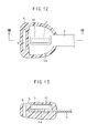
- Fig. 12 and Fig. 13 show a fifth embodiment of the present invention, in which a holding member 17 housing a transponder 7 is disposed along one of the surfaces of a key blank 4a.
- a holding member 17 housing a transponder 7 is disposed along one of the surfaces of a key blank 4a.
- the axial lines of the transponder 7 and a key shank 4 are not coaxial with each other in this embodiment, the strength of the grip portion 5 can be improved.
- a holding structure of the transponder 7 to the holding member 17 is similar with each of the first to third embodiments.
- the transponder as the signal transmitting/receiving means provided on the key is disposed to the grip portion of the key being housed in the inside of the holding member, stresses exerting on the transponder upon rotational operation of the key can be reduced, so that the strength and the rigidity can be improved without adopting any special shape, to easily decrease the size of the grip portion.
- the efficiency for the assembling operation can be improved further.
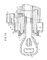
- Fig. 14 to Fig. 16 illustrate a sixth embodiment according to the present invention, in which corresponding components with those in the previous embodiments carry the same reference numerals for which duplicate explanations will be omitted.
- Fig. 14 is a side elevational cross sectional view illustrating a main portion of a key lock device for an ignition switch of an automobile to which the present invention is applied.
- a key 1 comprises a key shank 4 to be inserted in a cylinder lock 3 which is disposed in a housing 2 secured to a steering column and a grip portion 5 formed by insert molding a key blank 4a integrated to one end of the key shank 4.
- the cylinder lock 3 is made rotatable when mechanical codes coincide with respect to the key 1 upon insertion of the key 1 and it is connected with a mechanical contact that turns ON and OFF and the locking mechanism 5 that engages the steering shaft in accordance with the rotational position of the key 1.
- the key lock device is adapted to transmit and receive radiowave signals between the cylinder lock 3 and the key 1 to each other upon insertion of the key 1 into the cylinder lock 3, compare the code signal transmitted from the key 1 with a private code stored previously in the automobile and, if both of the codes coincide between them, judge that the inserted key is an authentic one thereby permitting the operation of the engine.
- coils 6 are disposed as a signal transmitting/ receiving means provided on the cylinder lock so as to externally and coaxially surround the cylinder lock 3 at the end of the key insertion hole and a transponder 7 as the signal transmitting/receiving means provided on the key is buried in the grip portion 5 of the key 1.
- the transponder 7 provided on the key 1 comprises a coiled antenna 7a, a transmitting/ receiving circuit 7b electrically connected with the antenna 7a, and an electronic circuit such as an IC chip 7c connected with the transmitting/receiving circuit 7b.
- the transponder 7 is housed in a glass tube closed at both ends each in a rounded shape.
- a controller 8 is connected to the key coils 6 disposed on the vehicle body and the controller 8 has at the inside a transmitting/receiving circuit 8a electrically connected with the cylinder coils 6, a control circuit 8b connected with the transmitting/receiving circuit 8a and a memory circuit 8c connected with the control circuit 8b. Further, the control circuit 8b is connected to an ON position detection switch SW associated operatively with the key cylinder 3.
- the key lock device when the key shank 4 is inserted into the key hole 3a of the key cylinder 3 and rotated to the "ON" position, closure of the ON position detection switch SW is detected by the control circuit 8b, by which the controller 8 is actuated, and a radiowave signal is transmitted by way of the transmitting/receiving circuit 8a from the cylinder coils 6.
- the antenna 7a in the transponder 7 receives the radiowave signal, an electromotive force is induced to the antenna 7a by the electro-magnetic induction.
- This electric power is converted into a DC current and supplied to the transmitting/ receiving circuit 7b and the IC chip 7c, to actuate both of the circuits 7b and 7c.
- the antenna 7a transmits a radiowave signal in accordance with an inherent code stored previously in the IC chip 7c.
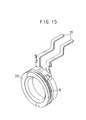
- the coils 6 are insert molded in the cover member 18 mounted to the end of the key insertion hole of the cylinder lock 3. As shown in Fig. 15, the coils 6 are wound around a bobbin 20 to which base ends of connection pins 19 for lead wires are previously secured by press fitting and they are insert-molded together with the bobbin 11 and the connection pins 19 in the cover member 18. In this case, the axial outer end face and the radial inner circumferential surface of the bobbin 20 are exposed directly and joined at the radial outer circumferential surface and the axial inner end face integrally with the cover member 18. This can reduce the axial size and the radial size of the cover member 18 as small as possible.
- a receptacle 21 for receiving a plug (not illustrated), to which lead wires from the controller 8 are connected, is molded integrally to the cover member 18 at the periphery of free ends of the connection pins.
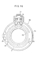
- the bobbin 20 is positioned coaxially with the cylinder lock 3 by direct fitting of the inner circumferential surface of the bobbin 20 to the outer circumferential surface of a cylinder cap 22 fitted to the end of the cylinder lock 3 at the key insertion hole. Then, the inner surface of a flange 23 extended radially outwardly from the axial inner end of the bobbin 20 abuts against the axial outer end of the housing 2 to determine axial positioning.
- protrusions 25 that are formed on the inner circumferential surface of a diametrically enlarged portion 24 extended from the outer circumferential edge of the flange 23 so as to surround the end of the housing 2 abut against the outer circumferential surface of the housing 2 to provide radial positioning (refer to Fig. 16).
- the cover member 18 is fixed to the housing 2 by securing an axially protruding stay 26 with machine screws.
Landscapes
- Engineering & Computer Science (AREA)
- Mechanical Engineering (AREA)
- Manufacturing & Machinery (AREA)
- Physics & Mathematics (AREA)
- General Physics & Mathematics (AREA)
- Lock And Its Accessories (AREA)
Abstract
Description
- The present invention concerns a key lock device for use in vehicles and, more in particular, it relates to a key lock device capable of inhibiting unauthorized use of a duplicate or counterfeit key.
- Various antitheft devices for automobiles have been proposed so far and it has been known a vehicle key lock device of such a structure as described, for example, in Japanese Patent Publication No. 15141/1992. In the proposed device, coils are provided on both of a key and a key cylinder that is disposed to a vehicle body for operating an ignition switch, and a magnetic circuit is established between both of the coils upon insertion of the key into the key cylinder to transmit and receive electric signals between each of the coils thereby judging whether the inserted key is an authentic one or not.
- In this prior art device, when a radiowave signal generated from the coils of the key cylinder is received by coils on the key, it is converted into an electric power to generate a code signal by the electric power. Since the key lock device of such a structure needs no electric cell on the key, the size and the cost of the device can be reduced. However, in the key lock device of the structure described above, it is still desirable that the efficiency of converting the radiowave signal into the electric power is made as high as possible.
- Further, in the key lock device of the structure described above, the coils provided on the key are wound around a shaft-shaped core combined between a key shank and a grip portion of the key and put into contact at two positions with an annular core for coils provided on the key cylinder upon insertion of the key into the key cylinder to establish a magnetic circuit. In this structure, since the key shank portion and the grip portion are intervened by the shaft-shaped core, it is difficult to integrally combine the key shank and the grip portion at high strength, and if it is intended to ensure sufficient strength and rigidity for the combined portion, there is a problem that the size of the grip portion is enlarged or the coil assembling work is made troublesome.
- Further, in the key lock device of the structure described above, since the intensity of radiowave signals induced by electro-magnetic coupling between the coils greatly depends on a positional accuracy between the key coils and the cylinder coils when the key is inserted into the cylinder lock, it is desirable that an aimed accuracy in assembling the coils can be obtained easily. Furthermore, since the coils and other relevant parts are incorporated in a restricted narrow space, it is desirable that the structure is made as compact as possible.
- In view of the foregoing problems in the prior art it is a primary object of the present invention to provide a key lock device capable of reducing the size of the device and improving a conversion efficiency from a radiowave signal into an electric power.
- It is another object of the present invention to provide a key lock device adapted such that the strength of a key can be improved without enlarging the size of a key grip portion or without complicating assembling operation of signal transmitting/ receiving means.
- A further object of the present invention is to provide a key lock device capable of easily obtaining an aimed assembling accuracy for coils and constituting them in a compact structure.
- According to the present invention, the foregoing primary object can be attained by providing a key lock device comprising:
- a signal transmitting/receiving means provided on a key having a key shank and a grip portion and a signal transmitting/receiving means provided on a key cylinder, in which
- radiowave signals are transmitted and received between both of the signal transmitting/receiving means to each other upon insertion of the key into the key cylinder, to judge whether the inserted key is an authentic one or not, wherein
- the signal transmitting/receiving means provided on the key cylinder has a coiled antenna wound coaxially around the key cylinder,
- the signal transmitting/receiving means provided on the key has a coiled antenna housed integrally in the grip portion of the key such that it situates coaxially with the coiled antenna of the signal transmitting/receiving means provided on the key cylinder when the key shank is inserted into the key cylinder.
-
- In a preferred embodiment, the signal transmitting/ receiving means provided on the key is housed in a hollow space formed by recessing a portion of a key blank for the grip portion of the key.
- In another preferred embodiment, the grip portion of the key is formed by resin molding the key blank together with the signal transmitting/receiving means provided on the key.
- In the above-mentioned constitution, since both of the coiled antennas of the signal transmitting/receiving means provided on the key cylinder and on the key, respectively, are situated coaxially to each other and magnetic fluxes generated through them by electro-magnetic coupling flow on a common axial line between both of the coiled antennas, so that the conversion efficiency from the radiowave into the electric power can be improved.
- Further, when the signal transmitting/receiving means is housed in the hollow space formed by recessing a portion of the key blank, the integrity and rigidity of the grip portion with the key shank can be strengthened.
- According to the present invention, another object can be attained by providing a key lock device comprising:
- a signal transmitting/receiving means provided on a key having a key shank and a grip portion and
- a signal transmitting/receiving means provided on a key cylinder, in which
- radiowave signals are transmitted and received between both of the signal transmitting/receiving means to each other upon insertion of the key into the key cylinder, to judge whether the inserted key is an authentic one or not wherein
- the signal transmitting/receiving means provided on the key cylinder has a coiled antenna wound coaxially around the key cylinder,
- the grip portion of the key has a holding member formed integrally at the inside thereof, and the signal transmitting/ recording means provided on the key is housed to the inside of the holding member.
-
- In a preferred embodiment, the holding member is incorporated to the inside of a hollow space formed by recessing a portion of a key blank for the grip portion of the key.
- In another preferred embodiment, the holding member has an aperture formed therein for insertion of the key shank, and the holding member and the key are integrated to each other by inserting the key shank through the aperture.
- In the above-mentioned constitution, since the signal transmitting/receiving means provided on the key is housed to the inside of the holding member, external forces which may exert on the signal transmitting/recording means can be reduced and the efficiency for the assembling operation of the key can be improved.
- According to the present invention, the further object can be attained by providing a key lock device comprising:
- a signal transmitting/receiving means provided on a key having a key shank and a grip portion and
- a signal transmitting/receiving means provided on a key cylinder, in which
- radiowave signals are transmitted and received between both of the signal transmitting/receiving means to each other upon insertion of the key into the key cylinder, to judge whether the inserted key is an authentic one or not, wherein
- the signal transmitting/receiving means provided on the key cylinder has a coiled antenna wound coaxially around the key cylinder, and
- the coiled antenna of the signal transmitting/receiving means provided on the key cylinder is insert molded in a cover member that is disposed, at a front end of the cylinder lock, coaxially with an axial line for the insertion of the key.
-
- In a preferred embodiment, the coiled antenna of the signal transmitting/receiving means provided on the key cylinder is wound around a bobbin to which based ends of connection pins for a connector are secured, and the coiled antenna, the bobbin and the connector are integrally molded together with the case member.
- With the above-mentioned constitution, since the coiled antenna of the signal transmitting/receiving means provided on the key cylinder is insert mold in the cover member disposed at the periphery of a key insertion hole of the cylinder lock, the positional accuracy of the coils relative to the key insertion hole is enhanced and the coil portion can be protected reliably. In particular, since the coils are wound around the bobbin to which the base ends of the connecting pins for the connector are secured and insert molded together with the bobbin, and the connector to the connection pins is molded integrally to form the cover member, the constitution can be simplified and made compact.
-
- Fig. 1 is a partially cut away front elevational view for a main portion of a key lock device to which the present invention is applied;
- Fig. 2 is a schematic circuit diagram in a key lock device to which the present invention is applied;
- Fig. 3 is a cross sectional view taken along line III-III in Fig. 1;
- Fig. 4 is a cross sectional view taken along line IV-IV in Fig. 1;
- Fig. 5 is an exploded perspective view for a main portion of the key according to the present invention;
- Fig. 6 is a view, corresponding to Fig. 1, illustrating a second embodiment according to the present invention;
- Fig. 7 is a cross sectional view taken along line VII-VII;
- Fig. 8 is a partially cut away front elevational view for a main portion of a key illustrating a third embodiment according to the present invention;
- Fig. 9 is a cross sectional view taken along line IX-IX in Fig. 8;
- Fig. 10 is a partially cut away front elevational view for a main portion of a key illustrating a fourth embodiment according to the present invention;
- Fig. 11 is a cross sectional view taken along line XI-XI in Fig. 10;
- Fig. 12 is a partially cut away front elevational view for a main portion of a key illustrating a fifth embodiment according to the present invention;
- Fig. 13 is a cross sectional view taken along line XIII-XIII in Fig. 12;
- Fig. 14 is a side elevational cross sectional view for a main portion of a key lock device illustrating a sixth embodiment according to the present invention;
- Fig. 15 is a perspective view for a coil bobbin element used in the embodiment shown in Fig. 14, and
- Fig. 16 is a side elevational view of a cover member shown in Fig. 15 in which coils are insert-molded.
-
- Preferred embodiments of the present invention will now be explained more specifically with reference to the accompanying drawings.
- Fig. 1 is a front elevational view illustrating a main portion of a key lock device for use in an automobile, to which the present invention is applied. In Fig. 1, a
key 1 used for ignition switch operation comprises akey shank 4 and akey grip portion 5 formed as a key blank integrated therewith. Thekey shank 4 is adapted to be inserted into akey hole 3a of akey cylinder 3 disposed to a steering column or acylinder housing 2. Thekey grip portion 5 is formed by insert-molding of a keyblank portion 4a. - In the same manner as in the known automobile ignition switch, the
key cylinder 3 has a "LOCK" position for fixing a steering wheel, an "OFF" position for turning off ignition, an "ACC" position for enabling operation of various car-mounted equipments, an "ON" position for turning on the ignition switch and a "ST" position for driving a starter motor. Thekey cylinder 3 is connected to a mechanical contact (not illustrated) which opens or closes in accordance with the rotational position of thekey 1 and to a locking mechanism which engages a steering shaft. - The key lock device is adapted to transmit/receive radiowave signals between the
key cylinder 3 and the key 1 when thekey 1 is inserted into thekey cylinder 3 and rotated to the "ON" position, compare a code signal generated from the key 1 with a private code stored previously in an electronic circuit of the automobile and, if the codes coincide with each other, judge that the key is an authentic one to permit the operation of the engine. As the means for this purpose, cylinder coils 6 are disposed so as to externally and coaxially surround thekey cylinder 3 at the front inlet end of akey hole 3a, whereas atransponder 7 is disposed to thegrip portion 5 of thekey 1, by which radiowave signals are transmitted/received between each of the cylinder coils 6 and thetransponder 7. - As shown in Fig. 2, the
transponder 7 as the signal transmitting/receiving means provided on thekey 1 comprises acoiled antenna 7a, a transmitting/receivingcircuit 7b electrically connected with theantenna 7a, and an electronic circuit such as an IC chip 7c connected with the transmitting/receivingcircuit 7b. Thetransponder 7 is incorporated in a glass tube closed at both ends each in a rounded shape (refer to Fig. 5). A controller 8 is connected to the cylinder coils 6 as a portion of the signal transmitting/receiving means provided on the vehicle body and the controller 8 has at the inside a transmitting/ receivingcircuit 8a electrically connected with the cylinder coils 6, acontrol circuit 8b connected with the transmitting/receivingcircuit 8a and amemory circuit 8c connected with thecontrol circuit 8b. Further, thecontrol circuit 8b is connected to an ON position detection switch SW associated operatively with thekey cylinder 3. - In the thus constituted key lock device, when the
key shank 4 is inserted into thekey hole 3a of thekey cylinder 3 and rotated to the "ON" position, closure of the ON position detection switch SW is detected by thecontrol circuit 8b, by which the controller 8 is actuated, and a radiowave is transmitted by way of the transmitting/receivingcircuit 8a from the cylinder coils 6. When the coiledantenna 7a in thetransponder 7 receives the radiowaves, an electromotive force is induced to theantenna 7a by the electro-magnetic induction effect. This electric power is converted into a DC current and supplied to the transmitting/receivingcircuit 7b and the IC chip 7c, to actuate both of thecircuits 7b and 7c. Then, theantenna 7a transmits a radiowave signal in accordance with an inherent code stored previously in the IC chip 7c. - When the cylinder coils 6 receive the inherent code signal transmitted from the
antenna 7a, it is inputted by way of the transmitting/receivingcircuit 8a to thecontrol circuit 8b. Thecontrol circuit 8b compares the inherent code signal from theantenna 7a with a private code stored previously in thememory circuit 8c. Then, when the inherent code coincides with the private code, a permission signal is outputted from the controller 8 to an engine control circuit not illustrated, to permit the operation of the engine. The engine control circuit has a function of actuating, for example, a starter circuit, a fuel circuit or an ignition circuit. On the other hand, if the codes do not coincide to each other, the operation of the engine is not enabled. - While it may suffice that the engine enabled state remains effective at least till the withdrawal of the
key 1, this state may be alternatively held for a certain period of time after the withdrawal of the key 1 or held until a door is locked after a driver gets off the car. This will be useful for saving electric power since it is no more necessary to conduct code comparison, for example, upon restarting after the withdrawal of thekey 1. - A key blank 4a is integrally formed at one end of a
key shank 4 of thekey 1. The key blank 4a has an enlarged width so as to facilitate gripping upon rotational operation of thekey 1. An intermediate portion of the key blank 4a is partially recessed to form atrapezoidal housing aperture 11 which is narrowed toward thekey shank 4. A holdingmember 12 made of a synthetic resin is housed within a hollow space defined by thehousing aperture 11. Alongitudinal hole 9 is disposed near the end of the key blank 4 on the side opposite to thekey shank 4 for allowing a key holder to pass therethrough. - As shown in Fig. 3 illustrating a cross section taken along line III-III in Fig. 1 and also in Fig. 4 illustrating a cross section taken along line IV-IV in Fig. 1, the holding
member 12 has amain portion 12a housed in thehousing aperture 11 andflanges 12b each extending sideways on one surface (upper surface) of themain portion 12a beyond thelateral side edge 9 of thehousing aperture 11. A holdingaperture 12c through which thetransponder 7 can be inserted is perforated to themain portion 12a of the holdingmember 12 in a longitudinal direction of the holdingmember 12. The holdingaperture 12c is formed at a position to be aligned with the axial center of thekey shank 4 in a state in which the holdingmember 12 is attached to thehousing aperture 11. - As best shown in Fig. 4,
axial ridges 12d are disposed on the inner circumferential surface of the holdingaperture 12c, each at a position of equally dividing (for instance, dividing by three) the circumference, respectively. Theridge 12d protrudes to such an extent as capable of resiliently supporting thetransponder 7 by the resiliency of the material of the holdingmember 12 itself upon inserting thetransponder 7 into the holdingaperture 12c (refer to an arrow A in Fig. 5). - A plurality of
vertical ridges 12e are also disposed on the lateral side of themain portion 12a of the holdingmember 12 at appropriate positions (for example, each two ridges on one side). Theridge 12e also protrudes to such an extent as capable of resiliently abutting themain portion 12a against the inner surface of thehousing aperture 11 by the resiliency of the material of the holdingmember 12 itself upon insertion into the housing aperture 11 (refer to an arrow B in Fig. 5). - When the key 1 having the structure described above is assembled, the
transponder 7 is at first inserted into the holdingaperture 12c of the holdingmember 12 in the direction of the arrow A in Fig. 5. Then, thetransponder 7 is held in a press-fitting state in the holdingaperture 12c under the effect of each of theridges 12d. Then, themain part 12a of the holdingmember 12 holding thetransponder 7 is inserted into thehousing aperture 11 of the key blank 4a, with theflanged portion 12b being at the back, in the direction of the arrow B in Fig. 5. Then, themain portion 12a is held in a press-fitting state in thehousing aperture 11 under the effect of each of theridges 12e. In this embodiment, the position for theflanges 12b is determined such that theflanges 12b abut against the upper surface of the key blank 4a with the axial centers for the holdingaperture 12c and thekey shank 4 being aligned with each other. That is, when the holdingmember 12 is mounted to the key blank 4a, thecoiled antenna 7a in thetransponder 7 is positioned coaxially with thekey shank 4. - As described above, since the
transponder 7 is held resiliently in the holdingmember 12 being raised from the inner circumferential wall by theridges 12d, it is protected from external forces and has increased shock resistance. Further, since thegrip portion 5 is formed by resin molding the outer surface of the key blank 4a so as to cover thetransponder 7 together with the holdingmember 12, thetransponder 7 can be fixed securely within thegrip portion 5. - When the thus constituted
key 1 is inserted into thekey hole 3a of thekey cylinder 3, thecoiled antenna 7a of thetransponder 7 and the cylinder coils 6 are opposed coaxially to each other. When magnetic fluxes are generated in a direction passing through the axial center of the coiledantenna 7a, the electro-magnetic coupling can be maximized and, accordingly, such positioning of thetransponder 7 relative to the cylinder coils 6 is advantageous, in view electro-magnetic conversion efficiency, by which radiowave communication can be conducted satisfactorily with respect to the cylinder coils 6. - Fig. 6 is a view, corresponding to Fig. 1, illustrating a second embodiment of a key lock device according to the present invention and Fig. 7 is a cross sectional view corresponding to Fig. 4, in which corresponding portions to those of the first embodiment carry same reference numerals, for which duplicate explanation will be omitted.
- In the second embodiment, a key blank 4a formed integrally with a
key shank 4 has such a length as the free end thereof is aligned with an outer end of atransponder 7. In the first embodiment, the circumference of thetransponder 7 is entirely surrounded with thehousing aperture 11. However, ahousing recess 13 is formed as a U-shaped configuration so as to surround thetransponder 7 on three sides in the second embodiment. Then, a holdingmember 14 for holding thetransponder 7 is formed such that amain portion 14a is housed tightly in thehousing recess 13, andflanges 14b are disposed, as shown in Fig. 7, so as to seize between them the inner circumferential edges on both surfaces of thehousing recess 13. A holding structure for thetransponder 7 by a holdingaperture 14c andridges 14d of the holdingmember 14 is similar to that in the first embodiment. - Also in the second embodiment, a key blank 4a made of metal is present along both lateral sides of the
transponder 7 and agrip portion 5 is molded integrally by resin molding the key blank 4a, so that stresses can be prevented from exerting on thetransponder 7 upon rotation of thekey 1. - The second embodiment is assembled by press-fitting the
transponder 7 in the holdingmember 14, engaging grooves each formed between a pair offlanges 14b disposed on each lateral side to opposing side edges of thehousing recess 13 at the open end and then inserting the holding member to the bottom of the housing recess 13 (rightmost end in Fig. 6). Subsequently, by resin molding the key blank 4a together with the holdingmember 14, agrip portion 5 of the same shape as in the first embodiment is molded integrally. Also in the second embodiment, the axial centers of the holdingaperture 14c and the key blank 4a are aligned with each other, and the positioning of thetransponder 7 relative to the cylinder coils 6 is advantageous in view of the electro-magnetic conversion in the same manner as in the first embodiment. - As has been described above according to the preferred embodiments of the present invention, since the coiled antenna on the key and the cylinder coils on the key cylinder are positioned coaxially with each other the efficiency of the radiowave communication between both of them can be optimized. Further, since the coiled antenna on the key is housed within the hollow space formed by recessing the base portion of the key main body, the efficiency for the assembling operation is satisfactory. Further, since the grip portion is formed by applying resin molding covering the base portion of the key blank housing the transponder to reduce the stresses exerting on the transponder upon rotation of the key, strength and rigidity can be ensured without taking any special shape and the size of the grip portion can be decreased easily.
- Fig. 8 and Fig. 9 illustrate a third embodiment of the key 1 according to the present invention. In the third embodiment, a
key shank 4 and a key blank 4a are orthogonal to each other in a T-shaped configuration. A holdingmember 15 has aninsertion aperture 15c for holding atransponder 7 and aninsertion aperture 15e formed in parallel with the holdingaperture 15c for inserting thekey shank 4. In the third embodiment, agrip portion 5 is formed, for example, by the steps of inserting to hold thetransponder 7 in theinsertion aperture 15c, inserting thekey shank 4 through theinsertion aperture 15e with one end of the holdingmember 15 being abutted against the key blank 4a at a joined portion with thekey shank 4 and insert molding the joined portion of thekey shank 4 and the key blank 4a together with the holdingmember 15. A holding structure for thetransponder 7 by the holdingaperture 15c and theridges 15d of the holdingmember 15 is similar with both of the first and the second embodiments. - Fig. 10 and Fig. 11 illustrate a fourth embodiment of the key 1 according to the present invention. A
key shank 4 and a key blank 4a are orthogonal to each other in a T-shaped configuration also in this fourth embodiment. A holdingmember 16 housing atransponder 7 is secured to a rear end (leftmost end) of the key blank 4a by means of heat caulking or the like and then agrip portion 5 is formed by resin molding. In this embodiment, since thetransponder 7 is not surrounded by the metal key blank 4a, undesired effects on the electro-magnetic coupling can be reduced. In this instance, a required torsional strength can be ensured by forming thegrip portion 5 with a synthetic resin material of high rigidity. A holding structure of thetransponder 7 to the holdingmember 16 is similar to each of the first to third embodiments. - Fig. 12 and Fig. 13 show a fifth embodiment of the present invention, in which a holding
member 17 housing atransponder 7 is disposed along one of the surfaces of a key blank 4a. Although the axial lines of thetransponder 7 and akey shank 4 are not coaxial with each other in this embodiment, the strength of thegrip portion 5 can be improved. Further, also in this embodiment, a holding structure of thetransponder 7 to the holdingmember 17 is similar with each of the first to third embodiments. - As has been described above, in the modified embodiments according to the present invention, since the transponder as the signal transmitting/receiving means provided on the key is disposed to the grip portion of the key being housed in the inside of the holding member, stresses exerting on the transponder upon rotational operation of the key can be reduced, so that the strength and the rigidity can be improved without adopting any special shape, to easily decrease the size of the grip portion. Particularly, in the embodiment having the holding member having the key shank insertion aperture, the efficiency for the assembling operation can be improved further.
- Fig. 14 to Fig. 16 illustrate a sixth embodiment according to the present invention, in which corresponding components with those in the previous embodiments carry the same reference numerals for which duplicate explanations will be omitted.
- Fig. 14 is a side elevational cross sectional view illustrating a main portion of a key lock device for an ignition switch of an automobile to which the present invention is applied.
- In Fig. 14, a
key 1 comprises akey shank 4 to be inserted in acylinder lock 3 which is disposed in ahousing 2 secured to a steering column and agrip portion 5 formed by insert molding a key blank 4a integrated to one end of thekey shank 4. - In the same way as the embodiments described previously, the
cylinder lock 3 is made rotatable when mechanical codes coincide with respect to the key 1 upon insertion of thekey 1 and it is connected with a mechanical contact that turns ON and OFF and thelocking mechanism 5 that engages the steering shaft in accordance with the rotational position of thekey 1. - The key lock device is adapted to transmit and receive radiowave signals between the
cylinder lock 3 and the key 1 to each other upon insertion of the key 1 into thecylinder lock 3, compare the code signal transmitted from the key 1 with a private code stored previously in the automobile and, if both of the codes coincide between them, judge that the inserted key is an authentic one thereby permitting the operation of the engine. For this purpose, coils 6 are disposed as a signal transmitting/ receiving means provided on the cylinder lock so as to externally and coaxially surround thecylinder lock 3 at the end of the key insertion hole and atransponder 7 as the signal transmitting/receiving means provided on the key is buried in thegrip portion 5 of thekey 1. - As shown already in Fig. 2, the
transponder 7 provided on thekey 1 comprises acoiled antenna 7a, a transmitting/ receivingcircuit 7b electrically connected with theantenna 7a, and an electronic circuit such as an IC chip 7c connected with the transmitting/receivingcircuit 7b. Thetransponder 7 is housed in a glass tube closed at both ends each in a rounded shape. A controller 8 is connected to thekey coils 6 disposed on the vehicle body and the controller 8 has at the inside a transmitting/receivingcircuit 8a electrically connected with the cylinder coils 6, acontrol circuit 8b connected with the transmitting/receivingcircuit 8a and amemory circuit 8c connected with thecontrol circuit 8b. Further, thecontrol circuit 8b is connected to an ON position detection switch SW associated operatively with thekey cylinder 3. - In the thus constituted key lock device, when the
key shank 4 is inserted into thekey hole 3a of thekey cylinder 3 and rotated to the "ON" position, closure of the ON position detection switch SW is detected by thecontrol circuit 8b, by which the controller 8 is actuated, and a radiowave signal is transmitted by way of the transmitting/receivingcircuit 8a from the cylinder coils 6. When theantenna 7a in thetransponder 7 receives the radiowave signal, an electromotive force is induced to theantenna 7a by the electro-magnetic induction. This electric power is converted into a DC current and supplied to the transmitting/ receivingcircuit 7b and the IC chip 7c, to actuate both of thecircuits 7b and 7c. Then, theantenna 7a transmits a radiowave signal in accordance with an inherent code stored previously in the IC chip 7c. - When the cylinder coils 6 receive the inherent code signal transmitted from the
antenna 7a, it is inputted by way of the transmitting/receivingcircuit 8a to thecontrol circuit 8b. Thecontrol circuit 8b compares the inherent code signal from theantenna 7a with a private code stored previously in thememory circuit 8c. Then, when the inherent code coincides with the private code, a permission signal is outputted from the controller 8 to an engine control circuit not illustrated, to permit the operation of the engine. On the other hand, if the codes do not coincide to each other, the operation of the engine is not enabled. - The
coils 6 are insert molded in thecover member 18 mounted to the end of the key insertion hole of thecylinder lock 3. As shown in Fig. 15, thecoils 6 are wound around abobbin 20 to which base ends of connection pins 19 for lead wires are previously secured by press fitting and they are insert-molded together with thebobbin 11 and the connection pins 19 in thecover member 18. In this case, the axial outer end face and the radial inner circumferential surface of thebobbin 20 are exposed directly and joined at the radial outer circumferential surface and the axial inner end face integrally with thecover member 18. This can reduce the axial size and the radial size of thecover member 18 as small as possible. Areceptacle 21 for receiving a plug (not illustrated), to which lead wires from the controller 8 are connected, is molded integrally to thecover member 18 at the periphery of free ends of the connection pins. - In the
cover member 18, thebobbin 20 is positioned coaxially with thecylinder lock 3 by direct fitting of the inner circumferential surface of thebobbin 20 to the outer circumferential surface of acylinder cap 22 fitted to the end of thecylinder lock 3 at the key insertion hole. Then, the inner surface of aflange 23 extended radially outwardly from the axial inner end of thebobbin 20 abuts against the axial outer end of thehousing 2 to determine axial positioning. Further,protrusions 25 that are formed on the inner circumferential surface of a diametricallyenlarged portion 24 extended from the outer circumferential edge of theflange 23 so as to surround the end of thehousing 2 abut against the outer circumferential surface of thehousing 2 to provide radial positioning (refer to Fig. 16). Thecover member 18 is fixed to thehousing 2 by securing anaxially protruding stay 26 with machine screws. - In this way, a high coaxial accuracy can be attained between the inserting axial line of the
key 1 and thecoils 6 by merely mounting thecover member 18 to the end of thecylinder lock 3 at the key insertion hole. In addition, since thecoils 6 and the connection portion for coil conductors and the connection pins 10 are completely buried in a synthetic resin material, thecoils 6 can be protected substantially completely. - In the modified embodiment according to the present invention, since the coils are insert-molded in the cover member disposed to the periphery of the key insertion hole of the
cylinder 6, the positional accuracy of the coils relative to the key insertion hole can be improved. In addition, water proofness, injury resistance and vibration proofness of the coil portion can be increased. Particularly, when the base portions of the connection pins are secured to the bobbin around which the coils are wound and insert molded together with the coils, and the lead connection port for the connection pins is molded integrally to the cover member, the structure can be much simplified and made compact.
Claims (3)
- A key lock device comprising:a signal transmitting/receiving means (7) provided on a key (1) having a key shank (4) and a grip portion (5) and a signal transmitting/receiving means (6) provided on a key cylinder (3), in whichradiowave signals are transmitted and received between both of the signal transmitting/receiving means (6, 7) to each other upon insertion of the key (1) into the key cylinder (3), to judge whether the inserted key is an authentic one or not, andthe signal transmitting/receiving means provided on the key cylinder (3) has a coiled antenna (6) wound coaxially around the key cylinder (3), characterized in thatthe signal transmitting/receiving means (7) provided on the key (1) has a coiled antenna (7a) integrally in the grip portion (5) of the key (1) such that it situates coaxially with the coiled antenna (6) of the signal transmitting/receiving means provided on the key cylinder (3) when the key shank (4) is inserted into the key cylinder,the grip portion (5) of the key (1) has a holding member (12) formed integrally at the inside thereof, and the signal transmitting/receiving means (7) provided on the key (1) is housed to the inside of the holding member (12), andthe signal transmitting/receiving means (7) provided on the key (1) is housed in a housing aperture (11) formed by recessing a portion of a key blank (4a) for the grip portion (5) of the key (1).
- A key lock device as defined in claim 1, wherein the grip portion (5) of the key (1) is formed by resin molding the key blank (4a) together with the signal transmitting/receiving means (7) provided on the key (1).
- A key lock device as defined in claim 1, wherein the holding member (15) has an aperture (15e) for inserting the key shank (4), and the holding member (15) and the key are integrated to each other by inserting the key shank (4) through the aperture (15e).
Applications Claiming Priority (7)
| Application Number | Priority Date | Filing Date | Title |
|---|---|---|---|
| JP9566694A JP3410545B2 (en) | 1994-04-07 | 1994-04-07 | Key device |
| JP9566694 | 1994-04-07 | ||
| JP9566594A JP3318111B2 (en) | 1994-04-07 | 1994-04-07 | Key device |
| JP9566594 | 1994-04-07 | ||
| JP33212894 | 1994-12-12 | ||
| JP33212894A JP3187269B2 (en) | 1994-12-12 | 1994-12-12 | Lock device |
| EP19950104896 EP0685620B1 (en) | 1994-04-07 | 1995-04-01 | Key lock device |
Related Parent Applications (1)
| Application Number | Title | Priority Date | Filing Date |
|---|---|---|---|
| EP19950104896 Division EP0685620B1 (en) | 1994-04-07 | 1995-04-01 | Key lock device |
Publications (3)
| Publication Number | Publication Date |
|---|---|
| EP1376480A2 true EP1376480A2 (en) | 2004-01-02 |
| EP1376480A3 EP1376480A3 (en) | 2004-09-01 |
| EP1376480B1 EP1376480B1 (en) | 2006-08-09 |
Family
ID=27307881
Family Applications (2)
| Application Number | Title | Priority Date | Filing Date |
|---|---|---|---|
| EP20030019327 Expired - Lifetime EP1376480B1 (en) | 1994-04-07 | 1995-04-01 | Key lock device |
| EP19950104896 Expired - Lifetime EP0685620B1 (en) | 1994-04-07 | 1995-04-01 | Key lock device |
Family Applications After (1)
| Application Number | Title | Priority Date | Filing Date |
|---|---|---|---|
| EP19950104896 Expired - Lifetime EP0685620B1 (en) | 1994-04-07 | 1995-04-01 | Key lock device |
Country Status (3)
| Country | Link |
|---|---|
| US (1) | US5632168A (en) |
| EP (2) | EP1376480B1 (en) |
| DE (2) | DE69532099T2 (en) |
Cited By (1)
| Publication number | Priority date | Publication date | Assignee | Title |
|---|---|---|---|---|
| EP1728695A1 (en) * | 2005-06-02 | 2006-12-06 | HONDA LOCK MFG. Co., LTD. | Operation device for vehicle ignition switch |
Families Citing this family (54)
| Publication number | Priority date | Publication date | Assignee | Title |
|---|---|---|---|---|
| US6035677A (en) | 1993-08-26 | 2000-03-14 | Strattec Security Corporation | Key assembly for vehicle ignition locks |
| US6427504B1 (en) | 1993-08-26 | 2002-08-06 | Strattec Security Corporation | Key assembly for vehicle ignition locks |
| AU693200B2 (en) * | 1994-05-20 | 1998-06-25 | Kabushiki Kaisha Tokai-Rika-Denki-Seisakusho | Key provided with built-in transmitter element |
| JPH07317394A (en) * | 1994-05-27 | 1995-12-05 | Tokai Rika Co Ltd | Card key equipped with transmitting element |
| DE19520211A1 (en) * | 1994-06-03 | 1996-02-01 | Strattec Security Corp | Electronic locking arrangement for a lock system |
| US5819564A (en) * | 1994-12-01 | 1998-10-13 | Nissan Motor Co., Ltd. | Key plate structure for automobile |
| DE19505190A1 (en) * | 1995-02-16 | 1996-08-22 | Marquardt Gmbh | Electronic key |
| JPH09100666A (en) * | 1995-10-05 | 1997-04-15 | Tokai Rika Co Ltd | Key cylinder |
| JP4080535B2 (en) * | 1996-02-29 | 2008-04-23 | コーニンクレッカ フィリップス エレクトロニクス エヌ ヴイ | System with lock and key working together according to transponder principle and key and lock for such system |
| US6308542B1 (en) * | 1996-10-11 | 2001-10-30 | Ortech Co. | Key assemblies and methods of making same |
| DE19644308C2 (en) * | 1996-10-24 | 1998-11-12 | Keso Gmbh | Flat key |
| US5826449A (en) * | 1996-11-12 | 1998-10-27 | The Whitaker Corporation | Electrical ignition key assembly |
| NL1005914C2 (en) * | 1997-04-28 | 1998-10-29 | Sgt Exploitatie Bv | Device for storing and / or treating chemicals. |
| IL121777A (en) * | 1997-09-16 | 2000-11-21 | Chen Zoor Yosi | Door lock system |
| US6442986B1 (en) | 1998-04-07 | 2002-09-03 | Best Lock Corporation | Electronic token and lock core |
| US5974844A (en) * | 1998-05-04 | 1999-11-02 | Ilco Unican Corp. | Combination key and transponder carrier |
| DE19906578B4 (en) * | 1999-02-17 | 2012-09-20 | Aug. Winkhaus Gmbh & Co. Kg | Key for a lock cylinder |
| DE19918162C2 (en) * | 1999-04-22 | 2001-03-15 | Opel Adam Ag | System for controlling functions of a vehicle, in particular a motor vehicle, primarily central locking and / or anti-theft alarm system, by remote control |
| DE10057005A1 (en) * | 1999-11-18 | 2001-08-23 | Siemens Automotive Corp Lp | Electronic locking system |
| DE19962219C2 (en) * | 1999-12-22 | 2002-01-17 | Siemens Ag | Component with a transponder, in particular an actuating part for a motor vehicle |
| US6457337B1 (en) * | 2000-06-14 | 2002-10-01 | Motorola, Inc. | Key, lock, and key and lock system |
| US6523380B1 (en) * | 2000-11-15 | 2003-02-25 | Strattec Security Corporation | Overmolded key including an ornamental element and method of making same |
| DE10131280A1 (en) * | 2001-06-28 | 2003-01-23 | Buga Schliessysteme Ag | Coded cylinder lock key has a decoding unit and two antennae cooperating with one in the lock housing |
| US7334443B2 (en) * | 2002-02-22 | 2008-02-26 | Master Lock Company Llc | Radio frequency electronic lock |
| JP2003253934A (en) * | 2002-03-06 | 2003-09-10 | Tokai Rika Co Ltd | Electronic key system |
| US7158008B2 (en) * | 2002-03-29 | 2007-01-02 | Datakey Electronincs, Inc. | Electronic key system and method |
| EP1371797A1 (en) * | 2002-05-13 | 2003-12-17 | European Community | Multi-purpose seal with a lock |
| US20040145449A1 (en) * | 2003-01-17 | 2004-07-29 | Kabushiki Kaisha Moric | Key operated antitheft device |
| JP2004270607A (en) * | 2003-03-11 | 2004-09-30 | Asahi Denso Co Ltd | Engine control system |
| JP4409194B2 (en) * | 2003-04-02 | 2010-02-03 | 朝日電装株式会社 | Engine control devices such as small propulsion boats |
| JP4705317B2 (en) * | 2003-04-16 | 2011-06-22 | 株式会社東海理化電機製作所 | Switch device, security system |
| JP4342207B2 (en) * | 2003-04-22 | 2009-10-14 | アイシン精機株式会社 | Vehicle door handle device |
| US7119667B2 (en) * | 2004-06-28 | 2006-10-10 | Delphi Technologies, Inc. | Integrated electronic security system for vehicle |
| JP4548206B2 (en) * | 2005-04-27 | 2010-09-22 | 株式会社デンソー | Wireless transceiver and manufacturing method thereof |
| JP4548205B2 (en) * | 2005-04-27 | 2010-09-22 | 株式会社デンソー | Wireless transceiver and manufacturing method thereof |
| SE528602C2 (en) * | 2005-06-10 | 2006-12-27 | Assa Ab | Key and way of producing such key |
| US7380428B2 (en) * | 2005-12-12 | 2008-06-03 | Kaba Ilco Corp. | Separable transponder key assembly |
| CN101816010A (en) * | 2007-07-19 | 2010-08-25 | 数据匙电子有限公司 | RF token and receptacle system and method |
| WO2009029864A1 (en) * | 2007-08-29 | 2009-03-05 | Datakey Electronics, Inc. | Data carrier system and method |
| JP4856686B2 (en) * | 2008-10-03 | 2012-01-18 | 株式会社東海理化電機製作所 | Electric steering lock device and motor damping structure |
| USD649894S1 (en) | 2008-12-30 | 2011-12-06 | Atek Products, Llc | Electronic token and data carrier |
| WO2010088556A1 (en) | 2009-01-30 | 2010-08-05 | Datakey Electronics, Inc. | Data carrier system having a compact footprint and methods of manufacturing the same |
| USD649895S1 (en) | 2009-01-30 | 2011-12-06 | Atek Products, Llc | Electronic token and data carrier |
| USD649896S1 (en) | 2009-01-30 | 2011-12-06 | Atek Products, Llc | Electronic token and data carrier receptacle |
| USD649486S1 (en) | 2009-07-09 | 2011-11-29 | ATEK Products , LLC | Electronic token and data carrier |
| JP2011027085A (en) | 2009-07-29 | 2011-02-10 | Honda Lock Mfg Co Ltd | Engine start/stop switch device |
| CN101936094A (en) * | 2010-08-20 | 2011-01-05 | 宁波永发集团有限公司 | Electronic spring mechanical lock core double-control safety box |
| FR2964241B1 (en) * | 2010-08-25 | 2012-08-17 | Schneider Electric Ind Sas | DEVICE FOR DETECTING AND REPORTING THE CHANGE OF STATUS OF A PUSH BUTTON |
| US8511122B1 (en) * | 2011-06-13 | 2013-08-20 | Joseph A. Mendoza | Remote key device |
| WO2013165958A1 (en) * | 2012-04-30 | 2013-11-07 | Kaba Ilco Corp. | Chipless key head and adapter for an electronic key |
| EP2877659A4 (en) * | 2012-07-25 | 2016-04-13 | Master Lock Co | Integrated antenna coil in a metallic body |
| DE102016101286A1 (en) * | 2015-12-14 | 2017-06-14 | Huf Hülsbeck & Fürst Gmbh & Co. Kg | Conditional access device |
| EP3182424A1 (en) * | 2015-12-14 | 2017-06-21 | Huf Hülsbeck & Fürst GmbH & Co. KG | Access authorization device |
| IT201800005348A1 (en) * | 2018-05-14 | 2019-11-14 | Improved commutator. |
Citations (3)
| Publication number | Priority date | Publication date | Assignee | Title |
|---|---|---|---|---|
| DE8911016U1 (en) * | 1989-09-14 | 1989-10-26 | Volkswagen Ag, 3180 Wolfsburg, De | |
| DE4317119A1 (en) * | 1993-05-21 | 1994-11-24 | Audi Ag | Anti-theft device as an immobiliser on a motor vehicle |
| US5433096A (en) * | 1993-08-26 | 1995-07-18 | Strattec Security Corporation | Key assembly for vehicle ignition locks |
Family Cites Families (13)
| Publication number | Priority date | Publication date | Assignee | Title |
|---|---|---|---|---|
| FR2518618B1 (en) * | 1981-12-17 | 1985-06-07 | Laperche Sa | ELECTRONICALLY CONTROLLED SAFETY BLOCK FOR LOCK |
| DE3501482A1 (en) * | 1985-01-18 | 1986-07-24 | Egon 5352 Zülpich Gelhard | DEVICE FOR CONTACTLESS COUPLING OF THE CONTROL AND POWER CURRENTS BETWEEN THE ELECTRONICS ON THE LOCKING CYLINDER AND THE ELECTRONICS IN THE KEY WITH AN ELECTRONIC / MECHANICAL LOCKING DEVICE |
| US4849749A (en) * | 1986-02-28 | 1989-07-18 | Honda Lock Manufacturing Co., Ltd. | Electronic lock and key switch having key identifying function |
| CA1308565C (en) * | 1987-01-20 | 1992-10-13 | Ford Motor Company Of Canada, Limited | Programmable key and improved lock assembly |
| JP2520698B2 (en) * | 1988-07-11 | 1996-07-31 | 株式会社アルファ | Optical electronic controller |
| GB8908386D0 (en) * | 1989-04-13 | 1989-06-01 | Chubb Lips Nederland Bv | Locks |
| US5117097A (en) * | 1990-02-27 | 1992-05-26 | Kabushiki Kaisha Tokai Rika Denki Seisakusho | Key system for a vehicle |
| JP2577487B2 (en) * | 1990-05-08 | 1997-01-29 | 日産自動車株式会社 | Automotive bumper mounting structure |
| EP0525730B1 (en) * | 1991-08-02 | 1995-11-02 | Kabushiki Kaisha Tokai Rika Denki Seisakusho | Cylinder lock and key |
| DE4234361A1 (en) * | 1992-03-06 | 1993-09-23 | Winkhaus Fa August | A CONNECTABLE ELECTRONIC LOCKING CYLINDER |
| DE4207161A1 (en) * | 1992-03-06 | 1993-09-09 | Winkhaus Fa August | ELECTRONIC LOCKING CYLINDER |
| US5398532A (en) * | 1993-01-14 | 1995-03-21 | Briggs & Stratton Corporation | Modular wiring harness for electronic vehicle ignition lock |
| JP2565632Y2 (en) * | 1993-06-08 | 1998-03-18 | 株式会社東海理化電機製作所 | Key cylinder device |
-
1995
- 1995-03-31 US US08/415,047 patent/US5632168A/en not_active Expired - Lifetime
- 1995-04-01 DE DE1995632099 patent/DE69532099T2/en not_active Expired - Lifetime
- 1995-04-01 EP EP20030019327 patent/EP1376480B1/en not_active Expired - Lifetime
- 1995-04-01 EP EP19950104896 patent/EP0685620B1/en not_active Expired - Lifetime
- 1995-04-01 DE DE1995635167 patent/DE69535167T2/en not_active Expired - Lifetime
Patent Citations (3)
| Publication number | Priority date | Publication date | Assignee | Title |
|---|---|---|---|---|
| DE8911016U1 (en) * | 1989-09-14 | 1989-10-26 | Volkswagen Ag, 3180 Wolfsburg, De | |
| DE4317119A1 (en) * | 1993-05-21 | 1994-11-24 | Audi Ag | Anti-theft device as an immobiliser on a motor vehicle |
| US5433096A (en) * | 1993-08-26 | 1995-07-18 | Strattec Security Corporation | Key assembly for vehicle ignition locks |
Non-Patent Citations (1)
| Title |
|---|
| "ignition-key transponders" AUTOMOTIVE ENGINEERING, vol. 101, no. 12, 1 December 1993 (1993-12-01), page 16, XP000417562 WARRENDALE US * |
Cited By (1)
| Publication number | Priority date | Publication date | Assignee | Title |
|---|---|---|---|---|
| EP1728695A1 (en) * | 2005-06-02 | 2006-12-06 | HONDA LOCK MFG. Co., LTD. | Operation device for vehicle ignition switch |
Also Published As
| Publication number | Publication date |
|---|---|
| DE69535167D1 (en) | 2006-09-21 |
| EP0685620A1 (en) | 1995-12-06 |
| US5632168A (en) | 1997-05-27 |
| DE69532099D1 (en) | 2003-12-18 |
| DE69532099T2 (en) | 2004-08-26 |
| EP0685620B1 (en) | 2003-11-12 |
| EP1376480B1 (en) | 2006-08-09 |
| DE69535167T2 (en) | 2007-06-28 |
| EP1376480A3 (en) | 2004-09-01 |
Similar Documents
| Publication | Publication Date | Title |
|---|---|---|
| EP1376480B1 (en) | Key lock device | |
| EP1445158B1 (en) | Engine switch device | |
| JP2007009414A (en) | Anti-theft system for vehicle | |
| KR100229916B1 (en) | Key identifying apparatus | |
| US6181025B1 (en) | Integral interrogator-coil circuit | |
| US5727408A (en) | Signal processing device with magnetism antenna and key device with the signal processing device | |
| JP3158010B2 (en) | Vehicle identification device | |
| EP1439101B1 (en) | Key operated antitheft device | |
| JP3187269B2 (en) | Lock device | |
| JP3597802B2 (en) | Key device | |
| JP3410545B2 (en) | Key device | |
| JP4685730B2 (en) | Shift device | |
| JP4302555B2 (en) | Key device | |
| JP3432275B2 (en) | Key device | |
| JP3151128B2 (en) | Vehicle key device | |
| JP3318111B2 (en) | Key device | |
| JP3328119B2 (en) | Assembly structure of vehicle key device | |
| JP3332748B2 (en) | Key device | |
| JP3979910B2 (en) | Immobilizer | |
| JP3280220B2 (en) | Transmitter / receiver antenna coil | |
| JP3009596B2 (en) | Key device | |
| JP2002083527A (en) | Ignition switch | |
| JP3745001B2 (en) | Vehicle key device | |
| JP6570171B2 (en) | Engine starter | |
| JPH08144589A (en) | Key device |
Legal Events
| Date | Code | Title | Description |
|---|---|---|---|
| PUAI | Public reference made under article 153(3) epc to a published international application that has entered the european phase |
Free format text: ORIGINAL CODE: 0009012 |
|
| 17P | Request for examination filed |
Effective date: 20030827 |
|
| AC | Divisional application: reference to earlier application |
Ref document number: 0685620 Country of ref document: EP Kind code of ref document: P |
|
| AK | Designated contracting states |
Kind code of ref document: A2 Designated state(s): DE FR GB |
|
| PUAL | Search report despatched |
Free format text: ORIGINAL CODE: 0009013 |
|
| AK | Designated contracting states |
Kind code of ref document: A3 Designated state(s): DE FR GB |
|
| RIC1 | Information provided on ipc code assigned before grant |
Ipc: 7B 60R 25/04 B Ipc: 7G 07C 9/00 A |
|
| AKX | Designation fees paid |
Designated state(s): DE FR GB |
|
| 17Q | First examination report despatched |
Effective date: 20050415 |
|
| GRAP | Despatch of communication of intention to grant a patent |
Free format text: ORIGINAL CODE: EPIDOSNIGR1 |
|
| GRAS | Grant fee paid |
Free format text: ORIGINAL CODE: EPIDOSNIGR3 |
|
| GRAA | (expected) grant |
Free format text: ORIGINAL CODE: 0009210 |
|
| AC | Divisional application: reference to earlier application |
Ref document number: 0685620 Country of ref document: EP Kind code of ref document: P |
|
| AK | Designated contracting states |
Kind code of ref document: B1 Designated state(s): DE FR GB |
|
| REG | Reference to a national code |
Ref country code: GB Ref legal event code: FG4D |
|
| REF | Corresponds to: |
Ref document number: 69535167 Country of ref document: DE Date of ref document: 20060921 Kind code of ref document: P |
|
| ET | Fr: translation filed | ||
| PLBE | No opposition filed within time limit |
Free format text: ORIGINAL CODE: 0009261 |
|
| STAA | Information on the status of an ep patent application or granted ep patent |
Free format text: STATUS: NO OPPOSITION FILED WITHIN TIME LIMIT |
|
| 26N | No opposition filed |
Effective date: 20070510 |
|
| PGFP | Annual fee paid to national office [announced via postgrant information from national office to epo] |
Ref country code: GB Payment date: 20130327 Year of fee payment: 19 |
|
| PGFP | Annual fee paid to national office [announced via postgrant information from national office to epo] |
Ref country code: DE Payment date: 20130327 Year of fee payment: 19 |
|
| PGFP | Annual fee paid to national office [announced via postgrant information from national office to epo] |
Ref country code: FR Payment date: 20130625 Year of fee payment: 19 |
|
| REG | Reference to a national code |
Ref country code: DE Ref legal event code: R119 Ref document number: 69535167 Country of ref document: DE |
|
| GBPC | Gb: european patent ceased through non-payment of renewal fee |
Effective date: 20140401 |
|
| REG | Reference to a national code |
Ref country code: FR Ref legal event code: ST Effective date: 20141231 |
|
| PG25 | Lapsed in a contracting state [announced via postgrant information from national office to epo] |
Ref country code: GB Free format text: LAPSE BECAUSE OF NON-PAYMENT OF DUE FEES Effective date: 20140401 Ref country code: DE Free format text: LAPSE BECAUSE OF NON-PAYMENT OF DUE FEES Effective date: 20141101 |
|
| REG | Reference to a national code |
Ref country code: DE Ref legal event code: R119 Ref document number: 69535167 Country of ref document: DE Effective date: 20141101 |
|
| PG25 | Lapsed in a contracting state [announced via postgrant information from national office to epo] |
Ref country code: FR Free format text: LAPSE BECAUSE OF NON-PAYMENT OF DUE FEES Effective date: 20140430 |