EP1380732A2 - Method and apparatus for desulphating a NOx trap - Google Patents
Method and apparatus for desulphating a NOx trap Download PDFInfo
- Publication number
- EP1380732A2 EP1380732A2 EP03103761A EP03103761A EP1380732A2 EP 1380732 A2 EP1380732 A2 EP 1380732A2 EP 03103761 A EP03103761 A EP 03103761A EP 03103761 A EP03103761 A EP 03103761A EP 1380732 A2 EP1380732 A2 EP 1380732A2
- Authority
- EP
- European Patent Office
- Prior art keywords
- trap
- engine
- temperature
- control apparatus
- engine control
- Prior art date
- Legal status (The legal status is an assumption and is not a legal conclusion. Google has not performed a legal analysis and makes no representation as to the accuracy of the status listed.)
- Granted
Links
Images


Classifications
-
- F—MECHANICAL ENGINEERING; LIGHTING; HEATING; WEAPONS; BLASTING
- F01—MACHINES OR ENGINES IN GENERAL; ENGINE PLANTS IN GENERAL; STEAM ENGINES
- F01N—GAS-FLOW SILENCERS OR EXHAUST APPARATUS FOR MACHINES OR ENGINES IN GENERAL; GAS-FLOW SILENCERS OR EXHAUST APPARATUS FOR INTERNAL COMBUSTION ENGINES
- F01N3/00—Exhaust or silencing apparatus having means for purifying, rendering innocuous, or otherwise treating exhaust
- F01N3/08—Exhaust or silencing apparatus having means for purifying, rendering innocuous, or otherwise treating exhaust for rendering innocuous
- F01N3/0807—Exhaust or silencing apparatus having means for purifying, rendering innocuous, or otherwise treating exhaust for rendering innocuous by using absorbents or adsorbents
- F01N3/0828—Exhaust or silencing apparatus having means for purifying, rendering innocuous, or otherwise treating exhaust for rendering innocuous by using absorbents or adsorbents characterised by the absorbed or adsorbed substances
- F01N3/0842—Nitrogen oxides
-
- F—MECHANICAL ENGINEERING; LIGHTING; HEATING; WEAPONS; BLASTING
- F01—MACHINES OR ENGINES IN GENERAL; ENGINE PLANTS IN GENERAL; STEAM ENGINES
- F01N—GAS-FLOW SILENCERS OR EXHAUST APPARATUS FOR MACHINES OR ENGINES IN GENERAL; GAS-FLOW SILENCERS OR EXHAUST APPARATUS FOR INTERNAL COMBUSTION ENGINES
- F01N13/00—Exhaust or silencing apparatus characterised by constructional features ; Exhaust or silencing apparatus, or parts thereof, having pertinent characteristics not provided for in, or of interest apart from, groups F01N1/00 - F01N5/00, F01N9/00, F01N11/00
- F01N13/009—Exhaust or silencing apparatus characterised by constructional features ; Exhaust or silencing apparatus, or parts thereof, having pertinent characteristics not provided for in, or of interest apart from, groups F01N1/00 - F01N5/00, F01N9/00, F01N11/00 having two or more separate purifying devices arranged in series
-
- F—MECHANICAL ENGINEERING; LIGHTING; HEATING; WEAPONS; BLASTING
- F01—MACHINES OR ENGINES IN GENERAL; ENGINE PLANTS IN GENERAL; STEAM ENGINES
- F01N—GAS-FLOW SILENCERS OR EXHAUST APPARATUS FOR MACHINES OR ENGINES IN GENERAL; GAS-FLOW SILENCERS OR EXHAUST APPARATUS FOR INTERNAL COMBUSTION ENGINES
- F01N3/00—Exhaust or silencing apparatus having means for purifying, rendering innocuous, or otherwise treating exhaust
- F01N3/08—Exhaust or silencing apparatus having means for purifying, rendering innocuous, or otherwise treating exhaust for rendering innocuous
- F01N3/0807—Exhaust or silencing apparatus having means for purifying, rendering innocuous, or otherwise treating exhaust for rendering innocuous by using absorbents or adsorbents
- F01N3/0814—Exhaust or silencing apparatus having means for purifying, rendering innocuous, or otherwise treating exhaust for rendering innocuous by using absorbents or adsorbents combined with catalytic converters, e.g. NOx absorption/storage reduction catalysts
-
- F—MECHANICAL ENGINEERING; LIGHTING; HEATING; WEAPONS; BLASTING
- F01—MACHINES OR ENGINES IN GENERAL; ENGINE PLANTS IN GENERAL; STEAM ENGINES
- F01N—GAS-FLOW SILENCERS OR EXHAUST APPARATUS FOR MACHINES OR ENGINES IN GENERAL; GAS-FLOW SILENCERS OR EXHAUST APPARATUS FOR INTERNAL COMBUSTION ENGINES
- F01N3/00—Exhaust or silencing apparatus having means for purifying, rendering innocuous, or otherwise treating exhaust
- F01N3/08—Exhaust or silencing apparatus having means for purifying, rendering innocuous, or otherwise treating exhaust for rendering innocuous
- F01N3/0807—Exhaust or silencing apparatus having means for purifying, rendering innocuous, or otherwise treating exhaust for rendering innocuous by using absorbents or adsorbents
- F01N3/0828—Exhaust or silencing apparatus having means for purifying, rendering innocuous, or otherwise treating exhaust for rendering innocuous by using absorbents or adsorbents characterised by the absorbed or adsorbed substances
- F01N3/0864—Oxygen
-
- F—MECHANICAL ENGINEERING; LIGHTING; HEATING; WEAPONS; BLASTING
- F02—COMBUSTION ENGINES; HOT-GAS OR COMBUSTION-PRODUCT ENGINE PLANTS
- F02D—CONTROLLING COMBUSTION ENGINES
- F02D37/00—Non-electrical conjoint control of two or more functions of engines, not otherwise provided for
- F02D37/02—Non-electrical conjoint control of two or more functions of engines, not otherwise provided for one of the functions being ignition
-
- F—MECHANICAL ENGINEERING; LIGHTING; HEATING; WEAPONS; BLASTING
- F02—COMBUSTION ENGINES; HOT-GAS OR COMBUSTION-PRODUCT ENGINE PLANTS
- F02D—CONTROLLING COMBUSTION ENGINES
- F02D41/00—Electrical control of supply of combustible mixture or its constituents
- F02D41/02—Circuit arrangements for generating control signals
- F02D41/021—Introducing corrections for particular conditions exterior to the engine
- F02D41/0235—Introducing corrections for particular conditions exterior to the engine in relation with the state of the exhaust gas treating apparatus
- F02D41/027—Introducing corrections for particular conditions exterior to the engine in relation with the state of the exhaust gas treating apparatus to purge or regenerate the exhaust gas treating apparatus
- F02D41/0275—Introducing corrections for particular conditions exterior to the engine in relation with the state of the exhaust gas treating apparatus to purge or regenerate the exhaust gas treating apparatus the exhaust gas treating apparatus being a NOx trap or adsorbent
- F02D41/028—Desulfurisation of NOx traps or adsorbent
-
- F—MECHANICAL ENGINEERING; LIGHTING; HEATING; WEAPONS; BLASTING
- F02—COMBUSTION ENGINES; HOT-GAS OR COMBUSTION-PRODUCT ENGINE PLANTS
- F02D—CONTROLLING COMBUSTION ENGINES
- F02D41/00—Electrical control of supply of combustible mixture or its constituents
- F02D41/02—Circuit arrangements for generating control signals
- F02D41/14—Introducing closed-loop corrections
- F02D41/1438—Introducing closed-loop corrections using means for determining characteristics of the combustion gases; Sensors therefor
- F02D41/1439—Introducing closed-loop corrections using means for determining characteristics of the combustion gases; Sensors therefor characterised by the position of the sensor
- F02D41/1441—Plural sensors
-
- F—MECHANICAL ENGINEERING; LIGHTING; HEATING; WEAPONS; BLASTING
- F01—MACHINES OR ENGINES IN GENERAL; ENGINE PLANTS IN GENERAL; STEAM ENGINES
- F01N—GAS-FLOW SILENCERS OR EXHAUST APPARATUS FOR MACHINES OR ENGINES IN GENERAL; GAS-FLOW SILENCERS OR EXHAUST APPARATUS FOR INTERNAL COMBUSTION ENGINES
- F01N2570/00—Exhaust treating apparatus eliminating, absorbing or adsorbing specific elements or compounds
- F01N2570/04—Sulfur or sulfur oxides
-
- F—MECHANICAL ENGINEERING; LIGHTING; HEATING; WEAPONS; BLASTING
- F01—MACHINES OR ENGINES IN GENERAL; ENGINE PLANTS IN GENERAL; STEAM ENGINES
- F01N—GAS-FLOW SILENCERS OR EXHAUST APPARATUS FOR MACHINES OR ENGINES IN GENERAL; GAS-FLOW SILENCERS OR EXHAUST APPARATUS FOR INTERNAL COMBUSTION ENGINES
- F01N2570/00—Exhaust treating apparatus eliminating, absorbing or adsorbing specific elements or compounds
- F01N2570/16—Oxygen
-
- F—MECHANICAL ENGINEERING; LIGHTING; HEATING; WEAPONS; BLASTING
- F02—COMBUSTION ENGINES; HOT-GAS OR COMBUSTION-PRODUCT ENGINE PLANTS
- F02D—CONTROLLING COMBUSTION ENGINES
- F02D2200/00—Input parameters for engine control
- F02D2200/02—Input parameters for engine control the parameters being related to the engine
- F02D2200/08—Exhaust gas treatment apparatus parameters
- F02D2200/0802—Temperature of the exhaust gas treatment apparatus
-
- F—MECHANICAL ENGINEERING; LIGHTING; HEATING; WEAPONS; BLASTING
- F02—COMBUSTION ENGINES; HOT-GAS OR COMBUSTION-PRODUCT ENGINE PLANTS
- F02D—CONTROLLING COMBUSTION ENGINES
- F02D2200/00—Input parameters for engine control
- F02D2200/02—Input parameters for engine control the parameters being related to the engine
- F02D2200/08—Exhaust gas treatment apparatus parameters
- F02D2200/0818—SOx storage amount, e.g. for SOx trap or NOx trap
-
- F—MECHANICAL ENGINEERING; LIGHTING; HEATING; WEAPONS; BLASTING
- F02—COMBUSTION ENGINES; HOT-GAS OR COMBUSTION-PRODUCT ENGINE PLANTS
- F02D—CONTROLLING COMBUSTION ENGINES
- F02D41/00—Electrical control of supply of combustible mixture or its constituents
- F02D41/02—Circuit arrangements for generating control signals
- F02D41/021—Introducing corrections for particular conditions exterior to the engine
- F02D41/0235—Introducing corrections for particular conditions exterior to the engine in relation with the state of the exhaust gas treating apparatus
- F02D41/027—Introducing corrections for particular conditions exterior to the engine in relation with the state of the exhaust gas treating apparatus to purge or regenerate the exhaust gas treating apparatus
- F02D41/0275—Introducing corrections for particular conditions exterior to the engine in relation with the state of the exhaust gas treating apparatus to purge or regenerate the exhaust gas treating apparatus the exhaust gas treating apparatus being a NOx trap or adsorbent
-
- F—MECHANICAL ENGINEERING; LIGHTING; HEATING; WEAPONS; BLASTING
- F02—COMBUSTION ENGINES; HOT-GAS OR COMBUSTION-PRODUCT ENGINE PLANTS
- F02D—CONTROLLING COMBUSTION ENGINES
- F02D41/00—Electrical control of supply of combustible mixture or its constituents
- F02D41/02—Circuit arrangements for generating control signals
- F02D41/14—Introducing closed-loop corrections
- F02D41/1401—Introducing closed-loop corrections characterised by the control or regulation method
- F02D41/1408—Dithering techniques
-
- F—MECHANICAL ENGINEERING; LIGHTING; HEATING; WEAPONS; BLASTING
- F02—COMBUSTION ENGINES; HOT-GAS OR COMBUSTION-PRODUCT ENGINE PLANTS
- F02D—CONTROLLING COMBUSTION ENGINES
- F02D41/00—Electrical control of supply of combustible mixture or its constituents
- F02D41/02—Circuit arrangements for generating control signals
- F02D41/14—Introducing closed-loop corrections
- F02D41/1438—Introducing closed-loop corrections using means for determining characteristics of the combustion gases; Sensors therefor
- F02D41/1444—Introducing closed-loop corrections using means for determining characteristics of the combustion gases; Sensors therefor characterised by the characteristics of the combustion gases
- F02D41/1446—Introducing closed-loop corrections using means for determining characteristics of the combustion gases; Sensors therefor characterised by the characteristics of the combustion gases the characteristics being exhaust temperatures
-
- F—MECHANICAL ENGINEERING; LIGHTING; HEATING; WEAPONS; BLASTING
- F02—COMBUSTION ENGINES; HOT-GAS OR COMBUSTION-PRODUCT ENGINE PLANTS
- F02D—CONTROLLING COMBUSTION ENGINES
- F02D41/00—Electrical control of supply of combustible mixture or its constituents
- F02D41/02—Circuit arrangements for generating control signals
- F02D41/18—Circuit arrangements for generating control signals by measuring intake air flow
- F02D41/187—Circuit arrangements for generating control signals by measuring intake air flow using a hot wire flow sensor
-
- Y—GENERAL TAGGING OF NEW TECHNOLOGICAL DEVELOPMENTS; GENERAL TAGGING OF CROSS-SECTIONAL TECHNOLOGIES SPANNING OVER SEVERAL SECTIONS OF THE IPC; TECHNICAL SUBJECTS COVERED BY FORMER USPC CROSS-REFERENCE ART COLLECTIONS [XRACs] AND DIGESTS
- Y02—TECHNOLOGIES OR APPLICATIONS FOR MITIGATION OR ADAPTATION AGAINST CLIMATE CHANGE
- Y02T—CLIMATE CHANGE MITIGATION TECHNOLOGIES RELATED TO TRANSPORTATION
- Y02T10/00—Road transport of goods or passengers
- Y02T10/10—Internal combustion engine [ICE] based vehicles
- Y02T10/12—Improving ICE efficiencies
Definitions
- This invention relates to exhaust after-treatment and, more particularly, to a method and apparatus for removing contaminants accumulated in a NO x trap.
- Lean burn engines usually operate at an air/fuel ratio (A/F) ⁇ 18 to obtain improved fuel economy.
- A/F air/fuel ratio
- TWC three-way catalyst
- A/F 14.65
- This NO x conversion occurs within an optimum temperature window of approximately 300°C to 400°C.
- the trap is preferably located underbody so that during hard, wide-open throttle (WOT) driving, the trap temperature does not exceed 800°C.
- WOT wide-open throttle
- the temperature of the three-way catalyst should not exceed approximately 1000°C.
- a fuel pump 10 pumps fuel from a tank 12 through a fuel line 14 to a set of injectors 16 which inject fuel into an internal combustion engine 18.
- the fuel injectors 16 are of conventional design and are positioned to inject fuel into their associated cylinder in precise quantities as determined by an electronic engine controller (EEC) 20.
- EEC electronic engine controller
- the fuel tank 12 contains liquid fuels, such as gasoline, methanol or a combination of fuel types.
- the EEC 20 comprises a microcomputer including a central processor unit (CPU) 54, read only memory (ROM) 56 for storing control programs, random access memory (RAM) 58, for temporary data storage which may also be used for counters or timers, and keep-alive memory (KAM) 60 for storing learned values.
- Data is input and output over I/O ports generally indicated at 62, and communicated internally over a conventional data bus generally indicated at 64.
- the EEC 20 transmits a fuel injector signal to the injectors 16 via signal line 64.
- the fuel injector signal is varied over time by EEC 20 to maintain an air/fuel ratio determined by the EEC 20.
- An indicator lamp generally indicated at 66 is controlled by the EEC 20 to provide an indication of the condition of the NO x trap 32 as determined by input data from the various sensors.
Abstract

Description
- This invention relates to exhaust after-treatment and, more particularly, to a method and apparatus for removing contaminants accumulated in a NOx trap.
- Lean burn engines usually operate at an air/fuel ratio (A/F) ≥ 18 to obtain improved fuel economy. However, the usual three-way catalyst (TWC) is most efficient at approximately stoichiometry, (A/F=14.65). Accordingly, it has been proposed to locate a NOx trap downstream of the TWC to store NOx during lean A/F operation and subsequently converting the NOx to N2 and O2 by operating the engine at a rich A/F. This NOx conversion occurs within an optimum temperature window of approximately 300°C to 400°C. The trap is preferably located underbody so that during hard, wide-open throttle (WOT) driving, the trap temperature does not exceed 800°C. The temperature of the three-way catalyst should not exceed approximately 1000°C.
- When operating with fuel containing contaminants such as sulphur, an accumulation of the contaminants in the trap causes a decrease in the amount of NOx the trap can absorb. The contaminants must be "burned" off or desorbed at temperatures ≥ 675°C and with an A/F ≤ 14.65 (rich). A previous method of raising the temperature of the trap from its usual operating temperature of approximately 300°C to 400°C to a temperature of at least 675°C, employs secondary air injection. This approach to SOx purging or desulphation of contaminants is expensive.
- Another approach to the problem employs a split exhaust manifold, separated TWC, or separated exhaust pipes, as proposed in US-A-5,758,493.
- US-A-5,657,625 proposes desulphating a NOx trap by simultaneously supplying a rich mixture to one set or bank of cylinders while the remaining cylinders are supplied with a weak mixture. In this way, oxidants produced by one set of cylinders react in the exhaust system with reductants produced by the other set of cylinders to raise the temperature of the exhaust gases.
- Reference is made to European Patent Application 98306144.1 (Publication No. 0 899 430) which contains the same disclosure as the present application but claims a method of engine operation comprising a sequence of the following steps estimating the amount of contaminant accumulated in a NOx trap located in the exhaust path of the engine; varying the A/F of the mixture supplied to the cylinders of the engine when the estimated amount of contaminant reaches a threshold amount to raise the temperature of the trap to a predetermined temperature sufficient to purge the NOx trap of contaminants; purging the trap of contaminant when said predetermined temperature is reached; and terminating the purging of said trap when a predetermined purge criteria is met; characterised in that the step of varying the A/F of the mixture supplied to the cylinders of the engine comprises supplying the engine cylinders with a mixture having an A/F that alternates in time between a rich value and a lean value, the frequency and the amplitude of the deviations of the A/F from its mean value being such as to heat the NOx trap to said predetermined temperature.
- According to the present invention, there is provided an engine control apparatus comprising:
- a NOx trap located in the exhaust passage of a multi-cylinder engine ;
- a catalytic converter located in said exhaust passage upstream of said NOx trap, the catalytic converter having a lower oxygen storage capacity than said NOx trap; and
- a computer programmed to:
- estimate when the trap should be purged of accumulated SOx,
- adjust the A/F of the mixture supplied to the engine to raise the temperature of the trap (32) to a purge temperature, and
- bias toward a rich A/F when the trap reaches said purge temperature to purge the trap of SOx.
-
- The invention will now be described, by way of example, with reference to the accompanying drawings, in which:
- Figure 1 shows a block diagram of the trap desulphation system of the present invention;
- Figure 2 is a graph of NOx trap midbed temperature vs. the A/F amplitude vs. the A/F modulation period;
- Figure 3 is a graph comparing NOx trap midbed temperature vs. A/F amplitude with and without a three way catalyst in the exhaust path; and
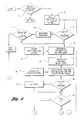
- Figures 4a and 4b are a flowchart of the trap desulphation method of the present invention.
-
- Referring now to the drawings and initially to Figure 1, a block diagram of the present invention is shown. A
fuel pump 10 pumps fuel from atank 12 through afuel line 14 to a set ofinjectors 16 which inject fuel into aninternal combustion engine 18. Thefuel injectors 16 are of conventional design and are positioned to inject fuel into their associated cylinder in precise quantities as determined by an electronic engine controller (EEC) 20. Thefuel tank 12 contains liquid fuels, such as gasoline, methanol or a combination of fuel types. - An exhaust system 22, comprising one or more exhaust pipes and an exhaust flange seen at 24, transports exhaust gas produced from combustion of an air/fuel mixture in the engine to a conventional three-way catalytic converter (TWC) 26. The
converter 26 contains catalyst material that chemically alters the exhaust gas to generate a catalysed exhaust gas. A heated exhaust gas oxygen (HEGO)sensor 28, detects the oxygen content of the exhaust gas generated by theengine 18, and transmits a representative signal overconductor 30 to theEEC 20. A NOx trap 32 is located downstream of theconverter 26 for trapping nitric oxide contained in the exhaust gas exiting the converter. A HEGOsensor 34 detects the oxygen content of the exhaust gas upstream of thetrap 32 while aHEGO sensor 36 detects the oxygen content of the exhaust gas downstream of thetrap 32. Thesensor respective conductors EEC 20. The NOx trap 32 contains atemperature sensor 42 for measuring the midbed temperature which is provided to theEEC 20 over theconductor 44. - Alternatively, the midbed temperature may be estimated using a computer model.
- Still other sensors, indicated generally at 46, provide additional information about engine performance to the
EEC 20, such as crankshaft position, angular velocity, throttle position, air temperature, etc. overconductor 50. The information from these sensors is used by theEEC 20 to control engine operation. - A mass
air flow sensor 48 positioned at the air intake ofengine 18 detects the amount of air inducted into an induction system of the engine and supplies an air flow signal overconductor 52 to theEEC 20. The air flow signal is utilised byEEC 20 to calculate a value that is indicative of the air mass flowing into the induction system. - The
EEC 20 comprises a microcomputer including a central processor unit (CPU) 54, read only memory (ROM) 56 for storing control programs, random access memory (RAM) 58, for temporary data storage which may also be used for counters or timers, and keep-alive memory (KAM) 60 for storing learned values. Data is input and output over I/O ports generally indicated at 62, and communicated internally over a conventional data bus generally indicated at 64. TheEEC 20 transmits a fuel injector signal to theinjectors 16 viasignal line 64. The fuel injector signal is varied over time byEEC 20 to maintain an air/fuel ratio determined by theEEC 20. An indicator lamp generally indicated at 66 is controlled by theEEC 20 to provide an indication of the condition of the NOx trap 32 as determined by input data from the various sensors. - The program stored in
ROM 58 implements an air/fuel strategy where the engine is operated in lean mode or relatively high air to fuel ratio (A/F) for fuel economy under certain engine speed/load conditions. The TWC 26 operates at temperatures between 400°C and 1000°C for good efficiency and durability. Thetrap 32 operates in a window of 300°C to 400°C for good efficiency. If the fuel contains sulphur, sulphur tends to deposit in the trap, reducing its NOx trapping efficiency and the ultimate conversion of NOx to harmless nitrogen and oxygen within the trap. To purge the trap of sulphur, the trap must be heated to approximately 650°C. The purging operation typically requires 3 to 10 minutes at that temperature. During the lean mode, NOx and SOx accumulates in the NOx trap. After substantially total sorption of thetrap 32, the purging operation is carried out. After purging is completed the EEC usually returns to the lean mode of operation. - An exotherm of sufficient temperature rise is created in the
trap 16 by modulation of the air-fuel mixture supplied to the engine cylinders through manipulation of the fuel injection quantities.A/F Modulation Schedule Stroke Cyl. 1 P E I C P E I C P E I C P E I C P E I C Cylinder 1 L L L L L L L L L L R R R R R R R R R R Cylinder 2 L L L L L L L L L L R R R R R R R R R R Cylinder 3 L L L L L L L L L L R R R R R R R R R R Cylinder 4 L L L L L L L L L L R R R R R R R R R R < - - - - - - - - τ - - - - - - - - - > - Table 1 shows an example of a typical fuel injection pattern. For this pattern, all cylinders are operated lean (L) for 10 events and all cylinders are operated rich (R) for 10 events. The resulting modulation period is equal to 20 engine events. The period can be chosen to be a fixed number of events or a fixed time τ. For the latter case, the number of engine events varies with engine speed (rpm). Typical periods may vary from two engine events to several seconds. The engine events are designated at P for power stroke, E for exhaust stroke, I for intake stroke, and C for compression stroke. The engine events are referenced to TDC of
cylinder number 1. The engine cylinder firing order is 1342. - Figures 2 and 3 demonstrate the attainment of midterm temperatures near 700° C within a lean NOx trap through the application of the A/F modulation technique. These results were obtained using a laboratory pulse flame combustor where the inlet gas to the NOx trap was preheated and controlled to 350° C. In both instances the A/F amplitude was varied between 0 and either 4 or 5 A/F units. For example, given a mean A/F of 14.5 (i.e., stoichiometry), an A/F amplitude of 4 units results in modulation between a lean A/F of 18.5 and a rich A/F of 10.5. Figure 2 illustrates the effect of A/F modulation amplitude and frequency on the exothermic temperature rise for a NOx trap with no TWC located upstream from the trap. The highest rate of exothermic temperature rise was obtained with a modulation period of 1 second (τ=1.0). For a fixed A/F modulation period of 1 second, Figure 3 compares the case where there is no TWC upstream of the NOx trap (graph A) to the case where a TWC and NOx trap are placed in series (graph B). Without an upstream TWC, a NOx midbed temperature of approximately 650° C is achieved for an A/F modulation amplitude of 2. With a TWC positioned upstream of the NOx trap, an A/F modulation amplitude of 4.5 was required in order to raise the NOx trap temperature to the desox (desulphation) temperature of 650° C. With the TWC positioned upstream of the NOx trap, larger A/F amplitudes are required in order to exceed the oxygen storage capacity of the TWC and hence create lean and rich breakthrough into the NOx trap. By judicious selection of the A/F amplitude and frequency, a portion of the exothermic temperature rise can be made to take place directly in the NOx trap rather than totally in the upstream TWC. Although symmetric modulation was discussed above, asymmetric modulation, in which the half-periods of the lean and rich modulation events are different, may be used in generating the exotherm.
- The system design forces HC, CO, AND O2 breakthrough in the TWC. This permits chemical energy to be transported from the exit of the TWC, through the exhaust pipe, to the trap. The design objective for the trap is to promote chemical reactions of HC, CO, and O2, which create an exotherm in the trap and raise its temperature. Preferably, breakthrough in the trap is minimised. The system design meets the following conditions: The combination of engine mass air flow and A/F modulation saturates the oxygen storage capacity of the TWC and approximately saturates the oxygen storage capacity of the trap. The rate at which the TWC and trap O2 storage sites fill with O2 is proportional to the product of engine mass air flow and the O2 concentration. For lean A/F, the O2 concentration is proportional to the difference between the exhaust A/F ratio and the stoichiometric A/F (typically 14.5).
- The A/F ratio modulation period τ may be chosen to be large with respect to the time necessary to fill the O2 storage sites in the TWC and small with respect to the time necessary to fill the O2 storage sites in the trap. The filling time is inversely proportional to the engine mass flow rate and the O2 concentration. The latter is proportional to the A/F ratio modulation span.
- The oxygen storage capacity of the TWC and trap can be varied through well known methods. The concentration of cerium in the washcoat can be changed and the physical size of the TWC and trap can be changed. Increasing both parameters tends to increase the oxygen storage. The oxygen storage capacity of the trap (C2) is significantly greater than the oxygen storage capacity of the TWC (C1). C1 is minimised so that most of the exotherm occurs in the trap rather than the TWC.
- During the desulphation process, the A/F ratio and spark advance are controlled. The A/F ratio span determines the exotherm in the trap, as discussed. However, the spark advance is preferably controlled to avoid power surges and sags during the desulphation. During the lean A/F desulphation event, the spark advance is adjusted to MBT. During the rich desulphation event, the spark advance is retarded. The desulphation process is started with lean modulation, to store oxygen in the trap. After the trap's oxygen storage capacity is attained, the A/F is switch rich. During the rich half of the event, a catalytic exotherm is generated in the trap, raising its temperature. After the temperature reaches the desired temperature, say 650° C, and remains at the desired temperature for a prescribed time during which the A/F is biased rich, the desulphation event is terminated.
- Referring now to Figure 4, a flowchart of the desulphation process is shown. When desox entry conditions exit as determined by the
block 70, a rich flag RFLG, and timers DESOXTMR and TOTTMR are reset and the A/F is set to stoichiometric as indicated ininitialisation block 72. Desox entry conditions may be based on the difference between lean to rich switching times of the upstream and downstream HEGO sensors as described in. copending application FMC0769 filed , assigned to the assignee of the present invention. Other well known criteria for estimating when the trap must be purged of SOx may also be used. Atblock 74 the trap temperature LNTTMP is compared with a predetermined desired desox temperature DESOXTMP of, for example, 650°C. LNTTMP may be obtained from a thermocouple or modelled. After the comparison step atblock 74, the amplitude and frequency of A/F modulation is determined atblock 76 based on engine speed and load and LNTTMP as input fromblock 78. The engine speed and load are the open loop components used in determining the modulation of the A/F necessary to arrive at the desired exotherm. The trap temperature provides a feedback component used in trimming the value of the amplitude and frequency determined from speed and load. Atblock 80 the desired spark timing to balance the engine torque for the respective lean and rich modulation periods is determined from previously obtained experimental data stored in look up tables. At block 82 the required number of rich cylinder events (NRCER) and lean cylinder events (NLCER) is determined based on the frequency of the A/F modulation and the engine speed. The required number of event determined at block 82 are adjusted to achieve a desired A/F of approximately stoichiometry as indicated by the rear ego signal input provided fromblock 84. If the trap temperature is below the desired desox temperature DESOXTMP as determined atblock 86, then the rich flag RFLG is checked atblock 90. The first time through this DESOX loop the flag is reset atblock 72 and accordingly a lean A/F is applied to all cylinders as indicated atblock 92. The spark timing is set atblock 94, to the value determined atblock 80, and a counter (NLCE) is incremented atblock 94 to record the number of lean cylinder events that have occurred. This number is compared atblock 98 with the number of lean cylinder events required (NLCER) as determined in block 82. When the events counted are equal to or greater than the number required, the rich flag RFLG is set and the counter (NLCE) is reset atblock 100. Until this occurs RFLG and a counter (NRCE) for counting the number of rich cylinder events are reset atblock 102 each lean cylinder event. - When the rich flag RFLG is set at
block 100, a rich A/F mixture will be supplied to all cylinders the next time though the loop, as indicated atblock 104. The rich spark timing value is set atblock 106 and the counter NRCE is incremented atblock 108 and compared atblock 110 with the number of cylinder events required (NRCER). The rich flag is set atblock 112 until the number of cylinder event is equal to or greater than the number required. At that time the flag RFLG and the counter NRCE are reset atblock 102. Thus, when purge mode entry conditions are met, the amplitude of the A/F is modulated to raise the temperature of the trap to the desired SOx purging temperature DESOXTMR. When the trap temperature is equal to or greater than DESOXTMP as determined atblock 86, the A/F is biased to the rich side as indicated atblock 88. This biasing may be accomplished by increasing the number of rich cylinder events relative to the number of lean cylinder events or otherwise supplying a relatively rich mixture to the engine over each modulation period to thereby purge the trap. This relatively rich A/F mixture is supplied for a time interval DESOXTIM. A timer DESOXTMR is incremented atblock 114 each time through the loop while the trap temperature is equal to or greater than DESOXTMP, as determined atblock 74, and compared with DESOXTIM at block 118. When the trap temperature has been equal to or greater than DESOXTMP for the time interval DESOXTIM the program is exited at 120. - At block 122 a check is made to determined whether the entry conditions still exists. If not the program is exited prior to expiration of DESOXTIM. If so, a timer TOTTMR is incremented each time through the loop at
block 124 and compared with fixed maximum time MAXTIM atblock 126. When MAXTIM is exceeded, trap damage is assumed and a diagnostic code is set atblock 128 and the program is exited. The indicator lamp 66(Figure 1) is illuminated to provide an indication that the damage code has been set. - Thus, there is described a control system design where modulation of A/F mixture supplied to the engine cylinders is provided to produce substantial exotherms in a lean NOx trap situated downstream of a conventional TWC, thereby raising the temperature of the trap and allowing a purging of SOx from the trap.
Claims (11)
- An engine control apparatus comprising:a NOx trap (32) located in the exhaust passage of a multi-cylinder engine (18);a catalytic converter (26) located in said exhaust passage upstream of said NOx trap (32), the catalytic converter (26) having a lower oxygen storage capacity than said NOx trap (32); anda computer (20) programmed to:estimate when the trap (32) should be purged of accumulated SOx,adjust the A/F of the mixture supplied to the engine (18) to raise the temperature of the trap (32) to a purge temperature, andbias toward a rich A/F when the trap (32) reaches said purge temperature to purge the trap of SOx.
- An engine control apparatus as claimed in claim 1, further comprising at least one exhaust gas oxygen sensor (28, 34, 36) located in said exhaust passage.
- An engine control apparatus as claimed in claims 1 or 2, wherein said apparatus further comprises an exhaust gas oxygen sensor (28) located upstream of said catalytic converter (26) .
- An engine control apparatus as claimed in any of the preceding claims, wherein said apparatus further comprises fuel injectors (16) which inject fuel into said multi-cylinder engine (18).
- An engine control apparatus as claimed in any of the preceding claims, wherein said NOx trap (32) contains a temperature sensor (42).
- An engine control apparatus as claimed in any of claims 1 to 4, wherein said computer (20) is further programmed to estimate temperature of said NOx trap.
- An engine control apparatus as claimed in any of the preceding claims, wherein said catalytic converter (26) has a washcoat including cerium.
- An engine control apparatus as claimed in any of the preceding claims, wherein said computer (20) is further programmed to adjust ignition timing during said purging of said NOx trap (32) .
- An engine control apparatus as claimed in any of the preceding claims, further comprising a mass air flow sensor (48) positioned at an air intake of the engine (18).
- An engine control apparatus as claimed in any of the preceding claims, wherein said purging from said trap (32) includes purging NOx.
- An engine control apparatus as claimed in any of the preceding claims, wherein said computer (20) is further programmed to bias toward a lean A/F after the trap is purged.
Applications Claiming Priority (3)
| Application Number | Priority Date | Filing Date | Title |
|---|---|---|---|
| US08/921,074 US5974788A (en) | 1997-08-29 | 1997-08-29 | Method and apparatus for desulfating a nox trap |
| US921074 | 1997-08-29 | ||
| EP98306144A EP0899430B1 (en) | 1997-08-29 | 1998-07-31 | Method for desulphating a NOx trap |
Related Parent Applications (1)
| Application Number | Title | Priority Date | Filing Date |
|---|---|---|---|
| EP98306144A Division EP0899430B1 (en) | 1997-08-29 | 1998-07-31 | Method for desulphating a NOx trap |
Publications (3)
| Publication Number | Publication Date |
|---|---|
| EP1380732A2 true EP1380732A2 (en) | 2004-01-14 |
| EP1380732A3 EP1380732A3 (en) | 2006-07-26 |
| EP1380732B1 EP1380732B1 (en) | 2009-08-19 |
Family
ID=25444878
Family Applications (3)
| Application Number | Title | Priority Date | Filing Date |
|---|---|---|---|
| EP03103761A Expired - Lifetime EP1380732B1 (en) | 1997-08-29 | 1998-07-31 | Method and apparatus for desulphating a NOx trap |
| EP03103762A Withdrawn EP1378645A3 (en) | 1997-08-29 | 1998-07-31 | Method and apparatus for purging a NOx trap |
| EP98306144A Expired - Lifetime EP0899430B1 (en) | 1997-08-29 | 1998-07-31 | Method for desulphating a NOx trap |
Family Applications After (2)
| Application Number | Title | Priority Date | Filing Date |
|---|---|---|---|
| EP03103762A Withdrawn EP1378645A3 (en) | 1997-08-29 | 1998-07-31 | Method and apparatus for purging a NOx trap |
| EP98306144A Expired - Lifetime EP0899430B1 (en) | 1997-08-29 | 1998-07-31 | Method for desulphating a NOx trap |
Country Status (4)
| Country | Link |
|---|---|
| US (2) | US5974788A (en) |
| EP (3) | EP1380732B1 (en) |
| JP (2) | JPH11148399A (en) |
| DE (2) | DE69841081D1 (en) |
Families Citing this family (189)
| Publication number | Priority date | Publication date | Assignee | Title |
|---|---|---|---|---|
| GB2324052A (en) * | 1997-04-11 | 1998-10-14 | Ford Motor Co | Heating of a storage trap |
| US5974788A (en) * | 1997-08-29 | 1999-11-02 | Ford Global Technologies, Inc. | Method and apparatus for desulfating a nox trap |
| US6148612A (en) * | 1997-10-13 | 2000-11-21 | Denso Corporation | Engine exhaust gas control system having NOx catalyst |
| EP0915244B1 (en) * | 1997-11-10 | 2003-08-06 | Mitsubishi Jidosha Kogyo Kabushiki Kaisha | Exhaust gas purifying apparatus of internal combustion engine |
| DE19813654A1 (en) * | 1998-03-27 | 1999-09-30 | Degussa | Method for operating an exhaust gas purification system containing a sulfur trap and a nitrogen oxide storage catalytic converter |
| SE514288C2 (en) * | 1998-05-27 | 2001-02-05 | Volvo Ab | Apparatus and process for sulfur regeneration of NOx adsorbent catalyst |
| DE19827195A1 (en) * | 1998-06-18 | 1999-12-23 | Volkswagen Ag | Process for the de-sulfation of a NOx storage catalytic converter |
| US6244046B1 (en) * | 1998-07-17 | 2001-06-12 | Denso Corporation | Engine exhaust purification system and method having NOx occluding and reducing catalyst |
| DE59914174D1 (en) * | 1998-08-05 | 2007-03-15 | Volkswagen Ag | Control of a NOx storage catalyst |
| DE19850786A1 (en) * | 1998-08-05 | 2000-02-17 | Volkswagen Ag | Regulation of a NOx storage catalytic converter |
| US6233925B1 (en) * | 1998-08-28 | 2001-05-22 | Toyota Jidosha Kabushiki Kaisha | Exhaust discharge control device for internal combustion engine |
| JP3370957B2 (en) * | 1998-09-18 | 2003-01-27 | トヨタ自動車株式会社 | Exhaust gas purification device for internal combustion engine |
| JP3632483B2 (en) * | 1999-02-05 | 2005-03-23 | マツダ株式会社 | Engine control device |
| JP4158268B2 (en) * | 1999-03-17 | 2008-10-01 | 日産自動車株式会社 | Engine exhaust purification system |
| JP3649034B2 (en) * | 1999-03-25 | 2005-05-18 | 日産自動車株式会社 | Engine exhaust purification system |
| US6293092B1 (en) * | 1999-04-12 | 2001-09-25 | General Motors Corporation | NOx adsorber system regeneration fuel control |
| DE19920515C2 (en) * | 1999-05-05 | 2003-03-20 | Daimler Chrysler Ag | Emission control system with nitrogen oxide adsorber and Desulfatisierungsverfahren this |
| DE19921972A1 (en) * | 1999-05-12 | 2000-11-16 | Volkswagen Ag | Process for desulfurizing a nitrogen oxides storage catalyst arranged in an exhaust gas channel of an IC engine comprises using operating parameters to raise the exhaust gas temperature and guarantee the working modulus of the engine |
| US6244043B1 (en) * | 1999-05-19 | 2001-06-12 | Ford Global Technologies, Inc. | Emission control device air/fuel ratio control system |
| DE19922962C2 (en) * | 1999-05-19 | 2003-02-27 | Daimler Chrysler Ag | Method for the periodic desulfurization of a nitrogen oxide or sulfur oxide storage of an emission control system |
| DE19923481A1 (en) * | 1999-05-21 | 2000-11-23 | Volkswagen Ag | Desulfurizing a nitrogen oxides storage catalyst arranged in the exhaust gas channel of an IC engine comprises adjusting the engine to a lean working modulus until a threshold value for lambda is reached in a first phase |
| GB2350697A (en) * | 1999-05-29 | 2000-12-06 | Ford Global Tech Inc | Purging of a NOx trap in an internal combustion engine |
| EP1059428B1 (en) * | 1999-06-08 | 2005-12-14 | Honda Giken Kogyo Kabushiki Kaisha | Exhaust gas purifying apparatus and controller for internal combustion engine |
| DE19928725A1 (en) * | 1999-06-23 | 2000-12-28 | Daimler Chrysler Ag | Process for desulfurizing nitrogen oxide adsorber of internal combustion engine exhaust gas purification device comprises determining carbon monoxide content of exhaust gas stream leaving the |
| EP1065351B1 (en) | 1999-07-02 | 2004-03-03 | Mitsubishi Jidosha Kogyo Kabushiki Kaisha | Exhaust gas purifying apparatus of internal combustion engine |
| DE19935341A1 (en) * | 1999-07-28 | 2001-02-01 | Volkswagen Ag | Method for controlling an exhaust gas temperature of a lean-burn internal combustion engine during desulfurization of a catalytic converter |
| JP3613083B2 (en) * | 1999-08-09 | 2005-01-26 | 株式会社日立製作所 | Exhaust purification control device |
| JP2001050086A (en) * | 1999-08-09 | 2001-02-23 | Denso Corp | Air-fuel ratio control unit for internal combustion engine |
| DE19939988A1 (en) * | 1999-08-24 | 2001-03-15 | Daimler Chrysler Ag | Method for operating a diesel engine |
| IT1310465B1 (en) * | 1999-09-07 | 2002-02-18 | Magneti Marelli Spa | SELF-ADAPTIVE METHOD OF CONTROL OF AN EXHAUST SYSTEM FOR INTERNAL COMBUSTION ENGINES WITH COMMAND IGNITION. |
| GB9921376D0 (en) * | 1999-09-10 | 1999-11-10 | Johnson Matthey Plc | Improving catalyst performance |
| DE19960430B4 (en) * | 1999-12-15 | 2005-04-14 | Daimlerchrysler Ag | Emission control system with nitrogen oxide storage catalyst and sulfur oxide trap and operating method for this |
| DE19961165A1 (en) * | 1999-12-17 | 2001-08-02 | Volkswagen Ag | Process for the desulfurization of a NO¶x¶ storage catalytic converter arranged in an exhaust gas duct of an internal combustion engine |
| US6427437B1 (en) | 2000-03-17 | 2002-08-06 | Ford Global Technologies, Inc. | Method for improved performance of an engine emission control system |
| US6360529B1 (en) | 2000-03-17 | 2002-03-26 | Ford Global Technologies, Inc. | Method and apparatus for enabling lean engine operation upon engine start-up |
| US6360530B1 (en) | 2000-03-17 | 2002-03-26 | Ford Global Technologies, Inc. | Method and apparatus for measuring lean-burn engine emissions |
| US6487849B1 (en) | 2000-03-17 | 2002-12-03 | Ford Global Technologies, Inc. | Method and apparatus for controlling lean-burn engine based upon predicted performance impact and trap efficiency |
| US6434930B1 (en) | 2000-03-17 | 2002-08-20 | Ford Global Technologies, Inc. | Method and apparatus for controlling lean operation of an internal combustion engine |
| US6843051B1 (en) | 2000-03-17 | 2005-01-18 | Ford Global Technologies, Llc | Method and apparatus for controlling lean-burn engine to purge trap of stored NOx |
| US6327847B1 (en) * | 2000-03-17 | 2001-12-11 | Ford Global Technologies, Inc. | Method for improved performance of a vehicle |
| US6374597B1 (en) | 2000-03-17 | 2002-04-23 | Ford Global Technologies, Inc. | Method and apparatus for accessing ability of lean NOx trap to store exhaust gas constituent |
| US6487850B1 (en) | 2000-03-17 | 2002-12-03 | Ford Global Technologies, Inc. | Method for improved engine control |
| US6477832B1 (en) | 2000-03-17 | 2002-11-12 | Ford Global Technologies, Inc. | Method for improved performance of a vehicle having an internal combustion engine |
| US6708483B1 (en) | 2000-03-17 | 2004-03-23 | Ford Global Technologies, Llc | Method and apparatus for controlling lean-burn engine based upon predicted performance impact |
| US6499293B1 (en) | 2000-03-17 | 2002-12-31 | Ford Global Technologies, Inc. | Method and system for reducing NOx tailpipe emissions of a lean-burn internal combustion engine |
| US6810659B1 (en) | 2000-03-17 | 2004-11-02 | Ford Global Technologies, Llc | Method for determining emission control system operability |
| US6308515B1 (en) | 2000-03-17 | 2001-10-30 | Ford Global Technologies, Inc. | Method and apparatus for accessing ability of lean NOx trap to store exhaust gas constituent |
| US6629453B1 (en) | 2000-03-17 | 2003-10-07 | Ford Global Technologies, Llc | Method and apparatus for measuring the performance of an emissions control device |
| US6438944B1 (en) | 2000-03-17 | 2002-08-27 | Ford Global Technologies, Inc. | Method and apparatus for optimizing purge fuel for purging emissions control device |
| US6860100B1 (en) * | 2000-03-17 | 2005-03-01 | Ford Global Technologies, Llc | Degradation detection method for an engine having a NOx sensor |
| US6594989B1 (en) | 2000-03-17 | 2003-07-22 | Ford Global Technologies, Llc | Method and apparatus for enhancing fuel economy of a lean burn internal combustion engine |
| US6308697B1 (en) | 2000-03-17 | 2001-10-30 | Ford Global Technologies, Inc. | Method for improved air-fuel ratio control in engines |
| US6481199B1 (en) | 2000-03-17 | 2002-11-19 | Ford Global Technologies, Inc. | Control for improved vehicle performance |
| US6539704B1 (en) | 2000-03-17 | 2003-04-01 | Ford Global Technologies, Inc. | Method for improved vehicle performance |
| JP2001289093A (en) * | 2000-03-31 | 2001-10-19 | Hitachi Ltd | Exhaust control device for cylinder fuel injection engine |
| DE10025034A1 (en) * | 2000-05-20 | 2001-11-22 | Dmc2 Degussa Metals Catalysts | Operation of petrol engine with new three-way catalyst having leading and trailing lambda sensors, avoids monitoring with second sensor until its rich-running output voltage reduces |
| JP4250856B2 (en) * | 2000-05-24 | 2009-04-08 | 三菱自動車工業株式会社 | In-cylinder internal combustion engine |
| JP3687495B2 (en) * | 2000-06-26 | 2005-08-24 | 日産自動車株式会社 | Exhaust gas purification device for internal combustion engine |
| DE10035525A1 (en) * | 2000-07-21 | 2002-02-07 | Bosch Gmbh Robert | Process for operating a catalyst |
| US6418711B1 (en) | 2000-08-29 | 2002-07-16 | Ford Global Technologies, Inc. | Method and apparatus for estimating lean NOx trap capacity |
| DE10043098A1 (en) * | 2000-09-01 | 2002-07-11 | Volkswagen Ag | Process for NOx regeneration of a NOx storage catalytic converter |
| DE10043687A1 (en) * | 2000-09-04 | 2002-03-14 | Bosch Gmbh Robert | Coordination of various exhaust gas temperature requirements and appropriate heating or cooling measures |
| DE10045939B4 (en) * | 2000-09-16 | 2016-05-04 | Caterpillar Inc. | Sensor for determining the concentration of sulfur compounds in a liquid |
| US6691507B1 (en) | 2000-10-16 | 2004-02-17 | Ford Global Technologies, Llc | Closed-loop temperature control for an emission control device |
| DE10054005A1 (en) | 2000-11-01 | 2002-05-08 | Daimler Chrysler Ag | The system to clean exhaust gas emissions from an IC motor has a nitrogen oxide accumulator, and desulfurizing operating in full and partial modes according to registered temperatures |
| US6422003B1 (en) | 2000-11-15 | 2002-07-23 | General Motors Corporation | NOX catalyst exhaust feedstream control system |
| DE10113382A1 (en) * | 2001-03-20 | 2002-10-10 | Audi Ag | Method for heating a downstream catalyst in an exhaust gas system of an internal combustion engine |
| JP2002364415A (en) * | 2001-06-07 | 2002-12-18 | Mazda Motor Corp | Exhaust emission control device for engine |
| US6650991B2 (en) | 2001-06-19 | 2003-11-18 | Ford Global Technologies, Llc | Closed-loop method and system for purging a vehicle emission control |
| US6553754B2 (en) | 2001-06-19 | 2003-04-29 | Ford Global Technologies, Inc. | Method and system for controlling an emission control device based on depletion of device storage capacity |
| US6691020B2 (en) | 2001-06-19 | 2004-02-10 | Ford Global Technologies, Llc | Method and system for optimizing purge of exhaust gas constituent stored in an emission control device |
| US6694244B2 (en) | 2001-06-19 | 2004-02-17 | Ford Global Technologies, Llc | Method for quantifying oxygen stored in a vehicle emission control device |
| US6615577B2 (en) | 2001-06-19 | 2003-09-09 | Ford Global Technologies, Llc | Method and system for controlling a regeneration cycle of an emission control device |
| US6502387B1 (en) | 2001-06-19 | 2003-01-07 | Ford Global Technologies, Inc. | Method and system for controlling storage and release of exhaust gas constituents in an emission control device |
| US6453666B1 (en) | 2001-06-19 | 2002-09-24 | Ford Global Technologies, Inc. | Method and system for reducing vehicle tailpipe emissions when operating lean |
| US6487853B1 (en) | 2001-06-19 | 2002-12-03 | Ford Global Technologies. Inc. | Method and system for reducing lean-burn vehicle emissions using a downstream reductant sensor |
| US6467259B1 (en) | 2001-06-19 | 2002-10-22 | Ford Global Technologies, Inc. | Method and system for operating dual-exhaust engine |
| US6490860B1 (en) | 2001-06-19 | 2002-12-10 | Ford Global Technologies, Inc. | Open-loop method and system for controlling the storage and release cycles of an emission control device |
| US6604504B2 (en) | 2001-06-19 | 2003-08-12 | Ford Global Technologies, Llc | Method and system for transitioning between lean and stoichiometric operation of a lean-burn engine |
| US6546718B2 (en) | 2001-06-19 | 2003-04-15 | Ford Global Technologies, Inc. | Method and system for reducing vehicle emissions using a sensor downstream of an emission control device |
| US6463733B1 (en) | 2001-06-19 | 2002-10-15 | Ford Global Technologies, Inc. | Method and system for optimizing open-loop fill and purge times for an emission control device |
| US6539706B2 (en) | 2001-06-19 | 2003-04-01 | Ford Global Technologies, Inc. | Method and system for preconditioning an emission control device for operation about stoichiometry |
| JP4117120B2 (en) * | 2001-07-13 | 2008-07-16 | 株式会社日立製作所 | Control device for internal combustion engine |
| US7198952B2 (en) * | 2001-07-18 | 2007-04-03 | Toyota Jidosha Kabushiki Kaisha | Catalyst deterioration detecting apparatus and method |
| US20050042763A1 (en) * | 2002-08-06 | 2005-02-24 | Southwest Research Institute | Testing using diesel exhaust produced by a non-engine based test system |
| US7741127B2 (en) * | 2001-08-06 | 2010-06-22 | Southwest Research Institute | Method for producing diesel exhaust with particulate material for testing diesel engine aftertreatment devices |
| CN100489280C (en) | 2001-08-06 | 2009-05-20 | 西南研究会 | Method and apparatus for testing catalytic converter durability |
| US6983645B2 (en) * | 2002-08-06 | 2006-01-10 | Southwest Research Institute | Method for accelerated aging of catalytic converters incorporating engine cold start simulation |
| US20040007056A1 (en) * | 2001-08-06 | 2004-01-15 | Webb Cynthia C. | Method for testing catalytic converter durability |
| US7175422B2 (en) * | 2001-08-06 | 2007-02-13 | Southwest Research Institute | Method for accelerated aging of catalytic converters incorporating injection of volatilized lubricant |
| US6803236B2 (en) * | 2001-08-10 | 2004-10-12 | Delphi Technologies, Inc. | Diagnostic system for monitoring catalyst performance |
| US7276212B2 (en) | 2001-10-01 | 2007-10-02 | Engelhard Corporation | Exhaust articles for internal combustion engines |
| DE10151250A1 (en) * | 2001-10-17 | 2003-05-08 | Bayer Ag | Process for determining a complex correlation pattern from process and plant data |
| US6553757B1 (en) * | 2001-11-19 | 2003-04-29 | Ford Global Technologies, Llc | NOx purge air/fuel ratio selection |
| DE10158568A1 (en) * | 2001-11-29 | 2003-06-26 | Bosch Gmbh Robert | Process and plant for the regeneration, in particular desulfation, of a storage catalytic converter during exhaust gas cleaning |
| DE10160704B4 (en) * | 2001-12-11 | 2013-07-18 | Volkswagen Ag | Method for operating exhaust gas purification devices |
| JP2003232246A (en) * | 2002-02-08 | 2003-08-22 | Denso Corp | Air-fuel ratio control device for internal combustion engine |
| US6964157B2 (en) * | 2002-03-28 | 2005-11-15 | Ricardo, Inc | Exhaust emission control system and method for removal and storage of vehicle exhaust gas nitrogen oxides during cold operation |
| DE10220337B4 (en) * | 2002-05-07 | 2006-04-20 | Siemens Ag | A method of operating an internal combustion engine equipped with a three-way catalytic converter |
| JP3972726B2 (en) * | 2002-05-16 | 2007-09-05 | 日産自動車株式会社 | Exhaust gas purification device for internal combustion engine |
| US6568177B1 (en) | 2002-06-04 | 2003-05-27 | Ford Global Technologies, Llc | Method for rapid catalyst heating |
| US7168239B2 (en) | 2002-06-04 | 2007-01-30 | Ford Global Technologies, Llc | Method and system for rapid heating of an emission control device |
| US6758185B2 (en) | 2002-06-04 | 2004-07-06 | Ford Global Technologies, Llc | Method to improve fuel economy in lean burn engines with variable-displacement-like characteristics |
| US6715462B2 (en) | 2002-06-04 | 2004-04-06 | Ford Global Technologies, Llc | Method to control fuel vapor purging |
| US6725830B2 (en) | 2002-06-04 | 2004-04-27 | Ford Global Technologies, Llc | Method for split ignition timing for idle speed control of an engine |
| US6769398B2 (en) | 2002-06-04 | 2004-08-03 | Ford Global Technologies, Llc | Idle speed control for lean burn engine with variable-displacement-like characteristic |
| US6735938B2 (en) | 2002-06-04 | 2004-05-18 | Ford Global Technologies, Llc | Method to control transitions between modes of operation of an engine |
| US6868827B2 (en) * | 2002-06-04 | 2005-03-22 | Ford Global Technologies, Llc | Method for controlling transitions between operating modes of an engine for rapid heating of an emission control device |
| US6736121B2 (en) | 2002-06-04 | 2004-05-18 | Ford Global Technologies, Llc | Method for air-fuel ratio sensor diagnosis |
| US6736120B2 (en) | 2002-06-04 | 2004-05-18 | Ford Global Technologies, Llc | Method and system of adaptive learning for engine exhaust gas sensors |
| US6745747B2 (en) | 2002-06-04 | 2004-06-08 | Ford Global Technologies, Llc | Method for air-fuel ratio control of a lean burn engine |
| US7299137B2 (en) | 2002-08-06 | 2007-11-20 | Southwest Research Institute | Method for drive cycle simulation using non-engine based test system |
| US7412335B2 (en) * | 2002-08-06 | 2008-08-12 | Southwest Research Institute | Component evaluations using non-engine based test system |
| US7212926B2 (en) * | 2002-08-06 | 2007-05-01 | Southwest Research Institute | Testing using a non-engine based test system and exhaust product comprising alternative fuel exhaust |
| JP2004068700A (en) * | 2002-08-06 | 2004-03-04 | Toyota Motor Corp | Exhaust gas purification method |
| DE10238771B4 (en) * | 2002-08-23 | 2009-01-22 | Umicore Ag & Co. Kg | Process for desulfating a nitrogen oxide storage catalyst |
| JP3925357B2 (en) * | 2002-08-30 | 2007-06-06 | いすゞ自動車株式会社 | Control method of exhaust gas purification system |
| DE10240977A1 (en) * | 2002-09-05 | 2004-03-18 | Robert Bosch Gmbh | Method for operating an internal combustion engine and internal combustion engine itself |
| DE10246505A1 (en) * | 2002-10-05 | 2004-04-15 | Robert Bosch Gmbh | Method for operating an internal combustion engine and the internal combustion engine itself |
| US6832473B2 (en) * | 2002-11-21 | 2004-12-21 | Delphi Technologies, Inc. | Method and system for regenerating NOx adsorbers and/or particulate filters |
| JP4385593B2 (en) * | 2002-12-10 | 2009-12-16 | トヨタ自動車株式会社 | Exhaust gas purification device for internal combustion engine |
| US6854264B2 (en) * | 2003-03-27 | 2005-02-15 | Ford Global Technologies, Llc | Computer controlled engine adjustment based on an exhaust flow |
| US7003944B2 (en) * | 2003-03-27 | 2006-02-28 | Ford Global Technologies, Llc | Computing device to generate even heating in exhaust system |
| US6766641B1 (en) | 2003-03-27 | 2004-07-27 | Ford Global Technologies, Llc | Temperature control via computing device |
| US7146799B2 (en) * | 2003-03-27 | 2006-12-12 | Ford Global Technologies, Llc | Computer controlled engine air-fuel ratio adjustment |
| DE10320890B4 (en) * | 2003-05-09 | 2013-01-31 | Robert Bosch Gmbh | Heating of catalysts in the operation of internal combustion engines with direct injection |
| JP2004353552A (en) * | 2003-05-29 | 2004-12-16 | Denso Corp | Catalyst early warming-up control device of internal combustion engine |
| JP2005009391A (en) * | 2003-06-18 | 2005-01-13 | Mitsubishi Motors Corp | Exhaust emission control device for internal combustion engine |
| FR2856732B1 (en) * | 2003-06-30 | 2007-02-16 | Volkswagen Ag | METHOD AND DEVICE FOR INFLUENCING THE TEMPERATURE OF A CATALYTIC SYSTEM |
| JP4016905B2 (en) * | 2003-08-08 | 2007-12-05 | トヨタ自動車株式会社 | Control device for internal combustion engine |
| DE10341930A1 (en) * | 2003-09-11 | 2005-04-21 | Audi Ag | A method for heating a in an exhaust system of a diesel internal combustion engine of a vehicle, in particular a motor vehicle, arranged catalyst and / or particulate filter on Desulfatisierungs- and / or Entrußungstemperatur and catalyst, in particular nitrogen oxide storage catalytic converter for exhaust systems of internal combustion engines |
| US20050072138A1 (en) * | 2003-10-01 | 2005-04-07 | White Vincent A. | Method and apparatus for improved catalytic converter performance |
| JP4062231B2 (en) * | 2003-10-16 | 2008-03-19 | トヨタ自動車株式会社 | Exhaust gas purification device for internal combustion engine |
| US7181905B2 (en) * | 2003-12-02 | 2007-02-27 | Ford Global Technologies, Llc | Lean-burn engine exhaust air-fuel and temperature management strategy for improved catalyst durability |
| US7284368B2 (en) * | 2003-12-02 | 2007-10-23 | Ford Global Technologies Llc | Computer device to control operation during catalyst desulfurization to preserve catalytic function |
| US7263433B2 (en) | 2003-12-02 | 2007-08-28 | Ford Global Technologies, Llc | Computer device to calculate emission control device functionality |
| SE0400904D0 (en) * | 2004-04-02 | 2004-04-02 | Volvo Technology Corp | Apparatus and method for removing sulfur from a hydrocarbon fuel |
| JP4232690B2 (en) | 2004-05-24 | 2009-03-04 | トヨタ自動車株式会社 | Fuel addition control method and exhaust purification device applied to exhaust purification device of internal combustion engine |
| US7111451B2 (en) * | 2004-09-16 | 2006-09-26 | Delphi Technologies, Inc. | NOx adsorber diagnostics and automotive exhaust control system utilizing the same |
| US7743606B2 (en) | 2004-11-18 | 2010-06-29 | Honeywell International Inc. | Exhaust catalyst system |
| US7182075B2 (en) | 2004-12-07 | 2007-02-27 | Honeywell International Inc. | EGR system |
| US7434386B2 (en) * | 2004-12-23 | 2008-10-14 | Caterpillar Inc. | System for monitoring exhaust gas concentrations |
| US7165399B2 (en) | 2004-12-29 | 2007-01-23 | Honeywell International Inc. | Method and system for using a measure of fueling rate in the air side control of an engine |
| US7275374B2 (en) | 2004-12-29 | 2007-10-02 | Honeywell International Inc. | Coordinated multivariable control of fuel and air in engines |
| US7591135B2 (en) | 2004-12-29 | 2009-09-22 | Honeywell International Inc. | Method and system for using a measure of fueling rate in the air side control of an engine |
| US7467614B2 (en) | 2004-12-29 | 2008-12-23 | Honeywell International Inc. | Pedal position and/or pedal change rate for use in control of an engine |
| US7328577B2 (en) | 2004-12-29 | 2008-02-12 | Honeywell International Inc. | Multivariable control for an engine |
| US7481046B2 (en) * | 2005-02-28 | 2009-01-27 | Ford Global Technologies, Llc | Method of desulfating a NOx storage and conversion device |
| US7752840B2 (en) | 2005-03-24 | 2010-07-13 | Honeywell International Inc. | Engine exhaust heat exchanger |
| US7469177B2 (en) | 2005-06-17 | 2008-12-23 | Honeywell International Inc. | Distributed control architecture for powertrains |
| US7389773B2 (en) * | 2005-08-18 | 2008-06-24 | Honeywell International Inc. | Emissions sensors for fuel control in engines |
| US7155334B1 (en) | 2005-09-29 | 2006-12-26 | Honeywell International Inc. | Use of sensors in a state observer for a diesel engine |
| US7765792B2 (en) | 2005-10-21 | 2010-08-03 | Honeywell International Inc. | System for particulate matter sensor signal processing |
| US7357125B2 (en) | 2005-10-26 | 2008-04-15 | Honeywell International Inc. | Exhaust gas recirculation system |
| US7412823B2 (en) * | 2005-12-02 | 2008-08-19 | Eaton Corporation | LNT desulfation strategy |
| US7669408B2 (en) * | 2005-12-02 | 2010-03-02 | Eaton Corporation | LNT desulfation strategy with reformer temperature management |
| US7415389B2 (en) | 2005-12-29 | 2008-08-19 | Honeywell International Inc. | Calibration of engine control systems |
| DE102006012656A1 (en) * | 2006-03-20 | 2007-09-27 | Siemens Ag | Method and device for operating an internal combustion engine |
| US7325394B2 (en) * | 2006-04-27 | 2008-02-05 | Ford Global Technologies Llc | System and method for desulfating a NOx trap |
| DE102006048905A1 (en) * | 2006-10-17 | 2008-04-30 | Robert Bosch Gmbh | Method for desulfurization of a storage catalyst and apparatus for carrying out the method |
| US7654076B2 (en) * | 2006-11-07 | 2010-02-02 | Cummins, Inc. | System for controlling absorber regeneration |
| US8240129B2 (en) * | 2006-12-20 | 2012-08-14 | Cummins Inc. | System and method for diagnosing operation of a NOx adsorber catalyst |
| US8061124B2 (en) * | 2006-12-20 | 2011-11-22 | Cummins, Inc. | Dynamic rich time capability for aftertreatment systems |
| DE102007044937B4 (en) * | 2007-09-20 | 2010-03-25 | Continental Automotive Gmbh | Method and device for operating an internal combustion engine |
| US7997063B2 (en) * | 2007-10-29 | 2011-08-16 | Ford Global Technologies, Llc | Controlled air-fuel ratio modulation air fuel sensor input |
| JP4930722B2 (en) * | 2007-12-25 | 2012-05-16 | トヨタ自動車株式会社 | Control device for internal combustion engine |
| DE102008005882B4 (en) * | 2008-01-24 | 2014-02-06 | Continental Automotive Gmbh | Method and device for operating an internal combustion engine |
| KR100986071B1 (en) | 2008-06-09 | 2010-10-07 | 현대자동차주식회사 | System for purifying exhaust gas of vehicle and control method thereof |
| WO2010003903A2 (en) * | 2008-07-08 | 2010-01-14 | Basf Se | Method for removing compounds containing sulfur from fuels |
| US8060290B2 (en) | 2008-07-17 | 2011-11-15 | Honeywell International Inc. | Configurable automotive controller |
| JP5057096B2 (en) * | 2008-10-07 | 2012-10-24 | 三菱自動車工業株式会社 | Engine control device |
| US8620461B2 (en) | 2009-09-24 | 2013-12-31 | Honeywell International, Inc. | Method and system for updating tuning parameters of a controller |
| US8459010B2 (en) * | 2010-02-26 | 2013-06-11 | General Electric Company | System and method for controlling nitrous oxide emissions of an internal combustion engine and regeneration of an exhaust treatment device |
| US8504175B2 (en) | 2010-06-02 | 2013-08-06 | Honeywell International Inc. | Using model predictive control to optimize variable trajectories and system control |
| US9677493B2 (en) | 2011-09-19 | 2017-06-13 | Honeywell Spol, S.R.O. | Coordinated engine and emissions control system |
| US9650934B2 (en) | 2011-11-04 | 2017-05-16 | Honeywell spol.s.r.o. | Engine and aftertreatment optimization system |
| US20130111905A1 (en) | 2011-11-04 | 2013-05-09 | Honeywell Spol. S.R.O. | Integrated optimization and control of an engine and aftertreatment system |
| HUE025999T2 (en) * | 2012-04-05 | 2016-04-28 | Delphi Int Operations Luxembourg Sarl | Lean nox trap desulfation process |
| EP3051367B1 (en) | 2015-01-28 | 2020-11-25 | Honeywell spol s.r.o. | An approach and system for handling constraints for measured disturbances with uncertain preview |
| EP3056706A1 (en) | 2015-02-16 | 2016-08-17 | Honeywell International Inc. | An approach for aftertreatment system modeling and model identification |
| EP3091212A1 (en) | 2015-05-06 | 2016-11-09 | Honeywell International Inc. | An identification approach for internal combustion engine mean value models |
| EP3734375B1 (en) | 2015-07-31 | 2023-04-05 | Garrett Transportation I Inc. | Quadratic program solver for mpc using variable ordering |
| US10272779B2 (en) | 2015-08-05 | 2019-04-30 | Garrett Transportation I Inc. | System and approach for dynamic vehicle speed optimization |
| US10415492B2 (en) | 2016-01-29 | 2019-09-17 | Garrett Transportation I Inc. | Engine system with inferential sensor |
| US10124750B2 (en) | 2016-04-26 | 2018-11-13 | Honeywell International Inc. | Vehicle security module system |
| US10036338B2 (en) | 2016-04-26 | 2018-07-31 | Honeywell International Inc. | Condition-based powertrain control system |
| EP3548729B1 (en) | 2016-11-29 | 2023-02-22 | Garrett Transportation I Inc. | An inferential flow sensor |
| US11057213B2 (en) | 2017-10-13 | 2021-07-06 | Garrett Transportation I, Inc. | Authentication system for electronic control unit on a bus |
| JP7283043B2 (en) * | 2018-09-18 | 2023-05-30 | 三菱自動車工業株式会社 | Exhaust control device for internal combustion engine |
Citations (5)
| Publication number | Priority date | Publication date | Assignee | Title |
|---|---|---|---|---|
| EP0580389A1 (en) * | 1992-07-24 | 1994-01-26 | Toyota Jidosha Kabushiki Kaisha | Exhaust gas purification apparatus for an internal combustion engine |
| EP0627548A1 (en) * | 1993-05-31 | 1994-12-07 | Toyota Jidosha Kabushiki Kaisha | An exhaust gas purification device for an engine |
| EP0636770A1 (en) * | 1993-01-19 | 1995-02-01 | Toyota Jidosha Kabushiki Kaisha | Exhaust gas cleaning device for an internal combustion engine |
| US5657625A (en) * | 1994-06-17 | 1997-08-19 | Mitsubishi Jidosha Kogyo Kabushiki Kaisha | Apparatus and method for internal combustion engine control |
| WO1998046868A1 (en) * | 1997-04-11 | 1998-10-22 | Ford Global Technologies, Inc. | Heating of a storage trap |
Family Cites Families (21)
| Publication number | Priority date | Publication date | Assignee | Title |
|---|---|---|---|---|
| US3696618A (en) | 1971-04-19 | 1972-10-10 | Universal Oil Prod Co | Control system for an engine system |
| US3708980A (en) | 1971-07-26 | 1973-01-09 | Gen Motors Corp | Internal combustion engine and method of operation |
| US3927525A (en) | 1973-05-25 | 1975-12-23 | Gen Motors Corp | Engine with exhaust manifold converter-reactor |
| US4036014A (en) | 1973-05-30 | 1977-07-19 | Nissan Motor Co., Ltd. | Method of reducing emission of pollutants from multi-cylinder engine |
| GB1490746A (en) | 1973-11-08 | 1977-11-02 | Nissan Motor | Method of and a system for reducing the quantities of noxious gases emitted into the atmosphere from an internal combustion engine |
| JPS50145707A (en) | 1974-05-15 | 1975-11-22 | ||
| JPS50148716A (en) | 1974-05-21 | 1975-11-28 | ||
| US4106448A (en) | 1975-03-03 | 1978-08-15 | Nippon Soken, Inc. | Internal combustion engine and method of operation |
| JPS5548089Y2 (en) | 1977-08-18 | 1980-11-11 | ||
| US4261170A (en) | 1977-09-26 | 1981-04-14 | Mitsubishi Jidosha Kogyo Kabushiki Kaisha | Exhaust-gas purifier |
| DE3614251C1 (en) | 1986-04-26 | 1987-01-29 | F & O Electronic Systems | Method for exhaust gas detoxification of an internal combustion engine using a catalytic system and device for carrying out the method |
| US5250268A (en) | 1990-03-09 | 1993-10-05 | Volkswagen Ag | Catalytic cleaning arrangement for exhaust from an internal combustion engine |
| US5077970A (en) * | 1990-06-11 | 1992-01-07 | Ford Motor Company | Method of on-board detection of automotive catalyst degradation |
| JPH04175418A (en) | 1990-11-07 | 1992-06-23 | Ebara Corp | Catalyst incorporating silencer |
| EP0625633B1 (en) | 1992-12-03 | 2000-03-15 | Toyota Jidosha Kabushiki Kaisha | Exhaust gas cleaning apparatus for internal combustion engines |
| JPH06272542A (en) | 1993-03-17 | 1994-09-27 | Hitachi Ltd | Apparatus and method for controlling exhaust emission of internal combustion engine |
| US5771685A (en) * | 1996-10-16 | 1998-06-30 | Ford Global Technologies, Inc. | Method for monitoring the performance of a NOx trap |
| US5746049A (en) * | 1996-12-13 | 1998-05-05 | Ford Global Technologies, Inc. | Method and apparatus for estimating and controlling no x trap temperature |
| US5758493A (en) * | 1996-12-13 | 1998-06-02 | Ford Global Technologies, Inc. | Method and apparatus for desulfating a NOx trap |
| US5832722A (en) * | 1997-03-31 | 1998-11-10 | Ford Global Technologies, Inc. | Method and apparatus for maintaining catalyst efficiency of a NOx trap |
| US5974788A (en) * | 1997-08-29 | 1999-11-02 | Ford Global Technologies, Inc. | Method and apparatus for desulfating a nox trap |
-
1997
- 1997-08-29 US US08/921,074 patent/US5974788A/en not_active Expired - Lifetime
-
1998
- 1998-07-31 EP EP03103761A patent/EP1380732B1/en not_active Expired - Lifetime
- 1998-07-31 DE DE69841081T patent/DE69841081D1/en not_active Expired - Lifetime
- 1998-07-31 EP EP03103762A patent/EP1378645A3/en not_active Withdrawn
- 1998-07-31 EP EP98306144A patent/EP0899430B1/en not_active Expired - Lifetime
- 1998-07-31 DE DE1998621171 patent/DE69821171T2/en not_active Expired - Lifetime
- 1998-08-24 JP JP10254603A patent/JPH11148399A/en active Pending
-
1999
- 1999-09-14 US US09/396,162 patent/US6199373B1/en not_active Expired - Lifetime
-
2005
- 2005-01-19 JP JP2005011609A patent/JP2005163794A/en active Pending
Patent Citations (5)
| Publication number | Priority date | Publication date | Assignee | Title |
|---|---|---|---|---|
| EP0580389A1 (en) * | 1992-07-24 | 1994-01-26 | Toyota Jidosha Kabushiki Kaisha | Exhaust gas purification apparatus for an internal combustion engine |
| EP0636770A1 (en) * | 1993-01-19 | 1995-02-01 | Toyota Jidosha Kabushiki Kaisha | Exhaust gas cleaning device for an internal combustion engine |
| EP0627548A1 (en) * | 1993-05-31 | 1994-12-07 | Toyota Jidosha Kabushiki Kaisha | An exhaust gas purification device for an engine |
| US5657625A (en) * | 1994-06-17 | 1997-08-19 | Mitsubishi Jidosha Kogyo Kabushiki Kaisha | Apparatus and method for internal combustion engine control |
| WO1998046868A1 (en) * | 1997-04-11 | 1998-10-22 | Ford Global Technologies, Inc. | Heating of a storage trap |
Also Published As
| Publication number | Publication date |
|---|---|
| EP0899430B1 (en) | 2004-01-21 |
| EP0899430A3 (en) | 2000-11-29 |
| EP1378645A2 (en) | 2004-01-07 |
| EP0899430A2 (en) | 1999-03-03 |
| EP1380732B1 (en) | 2009-08-19 |
| DE69821171D1 (en) | 2004-02-26 |
| JP2005163794A (en) | 2005-06-23 |
| US6199373B1 (en) | 2001-03-13 |
| JPH11148399A (en) | 1999-06-02 |
| DE69821171T2 (en) | 2004-11-18 |
| DE69841081D1 (en) | 2009-10-01 |
| EP1378645A3 (en) | 2006-07-26 |
| EP1380732A3 (en) | 2006-07-26 |
| US5974788A (en) | 1999-11-02 |
Similar Documents
| Publication | Publication Date | Title |
|---|---|---|
| EP0899430B1 (en) | Method for desulphating a NOx trap | |
| US5758493A (en) | Method and apparatus for desulfating a NOx trap | |
| US6516612B1 (en) | Exhaust gas purification device for an engine and A/F ratio control for early activating a NOx trapping catalyst | |
| US6289672B1 (en) | Exhaust gas purification device for an internal combustion engine | |
| US6679050B1 (en) | Exhaust emission control device for internal combustion engine | |
| KR100318001B1 (en) | Exhaust gas purifying device for cylinder injection internal combustion engine | |
| US20060154784A1 (en) | Method to improve fuel economy in lean burn engines with variable-displacement-like characteristics | |
| US20040118107A1 (en) | Exhaust emission aftertreatment | |
| US6244047B1 (en) | Method of purging lean NOx trap | |
| US5732550A (en) | Current supply control system of electrically heated catalytic converter of internal combustion engine | |
| WO1998012423A1 (en) | Engine control device | |
| EP1650419B1 (en) | Air/Fuel ratio control method | |
| US8997458B2 (en) | Air/fuel ratio control device for internal-combustion engine | |
| US6561166B2 (en) | Purge fuel canister measurement method and system | |
| GB2380694A (en) | A method and system for controlling an engine operating over a range of operating conditions. | |
| EP0897741B1 (en) | Exhaust gas purification system of internal combustion engine | |
| US5557929A (en) | Control system for internal combustion engine equipped with exhaust gas purifying catalyst | |
| GB2380432A (en) | A emission control system for an engine and method therefor. | |
| JP4127585B2 (en) | Exhaust gas purification device for internal combustion engine | |
| Hepburn et al. | Method and apparatus for desulfating a no x trap | |
| JP3843847B2 (en) | Air-fuel ratio control device for internal combustion engine | |
| JP3952109B2 (en) | Exhaust gas purification device for internal combustion engine | |
| EP1183090B1 (en) | Method of operating an internal combustion engine | |
| GB2380425A (en) | A method and system for controlling an internal combustion engine. | |
| JP3470405B2 (en) | Air-fuel ratio controller for lean-burn engines |
Legal Events
| Date | Code | Title | Description |
|---|---|---|---|
| PUAI | Public reference made under article 153(3) epc to a published international application that has entered the european phase |
Free format text: ORIGINAL CODE: 0009012 |
|
| 17P | Request for examination filed |
Effective date: 20031010 |
|
| AC | Divisional application: reference to earlier application |
Ref document number: 0899430 Country of ref document: EP Kind code of ref document: P |
|
| AK | Designated contracting states |
Kind code of ref document: A2 Designated state(s): DE FR GB |
|
| RAP1 | Party data changed (applicant data changed or rights of an application transferred) |
Owner name: FORD GLOBAL TECHNOLOGIES, LLC. |
|
| PUAL | Search report despatched |
Free format text: ORIGINAL CODE: 0009013 |
|
| AK | Designated contracting states |
Kind code of ref document: A3 Designated state(s): DE FR GB |
|
| RIC1 | Information provided on ipc code assigned before grant |
Ipc: F02D 37/02 20060101ALN20060621BHEP Ipc: F02D 41/02 20060101ALI20060621BHEP Ipc: F01N 3/08 20060101AFI20060621BHEP Ipc: F02D 41/14 20060101ALI20060621BHEP |
|
| AKX | Designation fees paid |
Designated state(s): DE FR GB |
|
| 17Q | First examination report despatched |
Effective date: 20080215 |
|
| GRAP | Despatch of communication of intention to grant a patent |
Free format text: ORIGINAL CODE: EPIDOSNIGR1 |
|
| GRAS | Grant fee paid |
Free format text: ORIGINAL CODE: EPIDOSNIGR3 |
|
| GRAA | (expected) grant |
Free format text: ORIGINAL CODE: 0009210 |
|
| AC | Divisional application: reference to earlier application |
Ref document number: 0899430 Country of ref document: EP Kind code of ref document: P |
|
| AK | Designated contracting states |
Kind code of ref document: B1 Designated state(s): DE FR GB |
|
| REG | Reference to a national code |
Ref country code: GB Ref legal event code: FG4D |
|
| REF | Corresponds to: |
Ref document number: 69841081 Country of ref document: DE Date of ref document: 20091001 Kind code of ref document: P |
|
| PLBE | No opposition filed within time limit |
Free format text: ORIGINAL CODE: 0009261 |
|
| STAA | Information on the status of an ep patent application or granted ep patent |
Free format text: STATUS: NO OPPOSITION FILED WITHIN TIME LIMIT |
|
| 26N | No opposition filed |
Effective date: 20100520 |
|
| PGFP | Annual fee paid to national office [announced via postgrant information from national office to epo] |
Ref country code: FR Payment date: 20120712 Year of fee payment: 15 |
|
| REG | Reference to a national code |
Ref country code: FR Ref legal event code: ST Effective date: 20140331 |
|
| PG25 | Lapsed in a contracting state [announced via postgrant information from national office to epo] |
Ref country code: FR Free format text: LAPSE BECAUSE OF NON-PAYMENT OF DUE FEES Effective date: 20130731 |
|
| REG | Reference to a national code |
Ref country code: DE Ref legal event code: R082 Ref document number: 69841081 Country of ref document: DE Representative=s name: DOERFLER, THOMAS, DR.-ING., DE |
|
| PGFP | Annual fee paid to national office [announced via postgrant information from national office to epo] |
Ref country code: GB Payment date: 20170626 Year of fee payment: 20 |
|
| PGFP | Annual fee paid to national office [announced via postgrant information from national office to epo] |
Ref country code: DE Payment date: 20170726 Year of fee payment: 20 |
|
| REG | Reference to a national code |
Ref country code: DE Ref legal event code: R071 Ref document number: 69841081 Country of ref document: DE |
|
| REG | Reference to a national code |
Ref country code: GB Ref legal event code: PE20 Expiry date: 20180730 |
|
| PG25 | Lapsed in a contracting state [announced via postgrant information from national office to epo] |
Ref country code: GB Free format text: LAPSE BECAUSE OF EXPIRATION OF PROTECTION Effective date: 20180730 |