EP1382894A2 - Vorrichtung zur Wanddurchführung von Rohrleitungen, Schläuchen oder elektrischen Kabeln für Kraftfahrzeuge - Google Patents
Vorrichtung zur Wanddurchführung von Rohrleitungen, Schläuchen oder elektrischen Kabeln für Kraftfahrzeuge Download PDFInfo
- Publication number
- EP1382894A2 EP1382894A2 EP03009688A EP03009688A EP1382894A2 EP 1382894 A2 EP1382894 A2 EP 1382894A2 EP 03009688 A EP03009688 A EP 03009688A EP 03009688 A EP03009688 A EP 03009688A EP 1382894 A2 EP1382894 A2 EP 1382894A2
- Authority
- EP
- European Patent Office
- Prior art keywords
- coupling
- wall
- coupling halves
- holder
- coupling half
- Prior art date
- Legal status (The legal status is an assumption and is not a legal conclusion. Google has not performed a legal analysis and makes no representation as to the accuracy of the status listed.)
- Granted
Links
Images


Classifications
-
- B—PERFORMING OPERATIONS; TRANSPORTING
- B60—VEHICLES IN GENERAL
- B60R—VEHICLES, VEHICLE FITTINGS, OR VEHICLE PARTS, NOT OTHERWISE PROVIDED FOR
- B60R16/00—Electric or fluid circuits specially adapted for vehicles and not otherwise provided for; Arrangement of elements of electric or fluid circuits specially adapted for vehicles and not otherwise provided for
- B60R16/02—Electric or fluid circuits specially adapted for vehicles and not otherwise provided for; Arrangement of elements of electric or fluid circuits specially adapted for vehicles and not otherwise provided for electric constitutive elements
- B60R16/0207—Wire harnesses
- B60R16/0215—Protecting, fastening and routing means therefor
- B60R16/0222—Grommets
-
- B—PERFORMING OPERATIONS; TRANSPORTING
- B60—VEHICLES IN GENERAL
- B60T—VEHICLE BRAKE CONTROL SYSTEMS OR PARTS THEREOF; BRAKE CONTROL SYSTEMS OR PARTS THEREOF, IN GENERAL; ARRANGEMENT OF BRAKING ELEMENTS ON VEHICLES IN GENERAL; PORTABLE DEVICES FOR PREVENTING UNWANTED MOVEMENT OF VEHICLES; VEHICLE MODIFICATIONS TO FACILITATE COOLING OF BRAKES
- B60T17/00—Component parts, details, or accessories of power brake systems not covered by groups B60T8/00, B60T13/00 or B60T15/00, or presenting other characteristic features
- B60T17/04—Arrangements of piping, valves in the piping, e.g. cut-off valves, couplings or air hoses
-
- F—MECHANICAL ENGINEERING; LIGHTING; HEATING; WEAPONS; BLASTING
- F16—ENGINEERING ELEMENTS AND UNITS; GENERAL MEASURES FOR PRODUCING AND MAINTAINING EFFECTIVE FUNCTIONING OF MACHINES OR INSTALLATIONS; THERMAL INSULATION IN GENERAL
- F16L—PIPES; JOINTS OR FITTINGS FOR PIPES; SUPPORTS FOR PIPES, CABLES OR PROTECTIVE TUBING; MEANS FOR THERMAL INSULATION IN GENERAL
- F16L37/00—Couplings of the quick-acting type
- F16L37/08—Couplings of the quick-acting type in which the connection between abutting or axially overlapping ends is maintained by locking members
- F16L37/084—Couplings of the quick-acting type in which the connection between abutting or axially overlapping ends is maintained by locking members combined with automatic locking
- F16L37/088—Couplings of the quick-acting type in which the connection between abutting or axially overlapping ends is maintained by locking members combined with automatic locking by means of a split elastic ring
-
- F—MECHANICAL ENGINEERING; LIGHTING; HEATING; WEAPONS; BLASTING
- F16—ENGINEERING ELEMENTS AND UNITS; GENERAL MEASURES FOR PRODUCING AND MAINTAINING EFFECTIVE FUNCTIONING OF MACHINES OR INSTALLATIONS; THERMAL INSULATION IN GENERAL
- F16L—PIPES; JOINTS OR FITTINGS FOR PIPES; SUPPORTS FOR PIPES, CABLES OR PROTECTIVE TUBING; MEANS FOR THERMAL INSULATION IN GENERAL
- F16L5/00—Devices for use where pipes, cables or protective tubing pass through walls or partitions
- F16L5/02—Sealing
- F16L5/027—Sealing by means of a joint of the quick-acting type
-
- F—MECHANICAL ENGINEERING; LIGHTING; HEATING; WEAPONS; BLASTING
- F16—ENGINEERING ELEMENTS AND UNITS; GENERAL MEASURES FOR PRODUCING AND MAINTAINING EFFECTIVE FUNCTIONING OF MACHINES OR INSTALLATIONS; THERMAL INSULATION IN GENERAL
- F16L—PIPES; JOINTS OR FITTINGS FOR PIPES; SUPPORTS FOR PIPES, CABLES OR PROTECTIVE TUBING; MEANS FOR THERMAL INSULATION IN GENERAL
- F16L5/00—Devices for use where pipes, cables or protective tubing pass through walls or partitions
- F16L5/02—Sealing
- F16L5/14—Sealing for double-walled or multi-channel pipes
Definitions
- the invention relates to a device for wall penetration of pipes, hoses or electrical cables - hereinafter referred to collectively as lines - for motor vehicles the preamble of claim 1.
- the invention has for its object a device for Wall ducting of pipes, hoses or electrical cables to create the respect their assembly is further simplified.
- the first coupling halves of the line couplings in each case by a holder to combine at least one group into at least two first coupling halves and the like to hold bundled coupling halves in plugs which are arranged in openings in a wall.
- the first coupling halves with the help of the holder can be in the vehicle Module to be installed, including its cables, pre-assembled, tested and outside the vehicle be prepared for assembly.
- this work is as well the subsequent assembly of the coupling halves in the wall openings easier.
- the assembly of the Coupling halves in the wall openings is particularly facilitated when there is no visual contact with the Wall openings when installing the lines is possible. Because one for each coupling half own opening in the wall of the body, this opening is usually as circular opening easy to install, easy to seal and otherwise different Easy to adapt vehicle variants with a different number of lines.
- the plugs are made of rubber-elastic material and in groups are summarized.
- the rubber-elastic material Coupling halves in an advantageous manner vibration isolated from the wall, so that the Lines kept decoupled from the body of the vehicle vibration and through the Wall are passed. Pressure fluctuations and other vibrations in the lines thus no longer a vibration excitation of the wall, which is clear in the interior of the vehicle would be heard.
- the manufacture and assembly of the Plug simplified because all the plugs required for a wall duct are combined into one part can be. At the same time, however, the individual sealing of each coupling half is guaranteed that a separate plug is provided in each wall opening. If, as further suggested, the Stopper are provided with a shoulder that with a provided on the first coupling half Interlocking together, no other means are required to stop the the first coupling halves in the wall opening securely and sealed.
- the device for wall bushing shown in FIG. 1 is used to carry out a bundle 2 of Lines 4, here hydraulic lines, through a wall 3 of a body not shown Motor vehicle.
- the lines 4 are provided with line couplings 5, each consisting of a first Coupling half 6 and a second coupling half 7 exist. Sections 4a, 4b of the lines 4 are each connected to the coupling halves 6, 7.
- the first coupling halves 6 are through a holder 8 summarized.
- the first coupling halves 6 are in the wall 3 by rubber-elastic plugs 9 sealed and vibration isolated.
- the first Coupling halves 6 are laterally provided with flats 10, which between projections 11 of the holder 8th are included, so that the first coupling halves 6 are held in the holder 8 against rotation.
- Fig. 3 shows a line 4 with a line coupling 5 in the assembled state in section.
- the first Section 4a of line 4 - here a hose section - is through with the first coupling half 6 Plugged in connected.
- the second section 4b of the line 4 - here a pipe section - is through the second Coupling half 7, which in the present example is designed as a union nut, with the first Coupling half 6 connected.
- the wall 3 has openings 12, only one of which is shown here by way of example.
- the plug 9 buttoned which with the adjacent plug 9 'for the sake of Ease of assembly is connected via a web 13.
- the plug 9 is through a circumferential nose 14, which engages behind the opening 12, held in the opening 12.
- the first coupling half 6 is received with a cylindrical region 15 in the plug 9 in such a way that the plug 9 forms a seal between the wall 3 and the first coupling half 6. End of the cylindrical region 15, a circumferential nose 16 is provided, which is provided in the stopper Paragraph 17 engages. In this way, the first coupling half 6 is held in place in the stopper 9.
- the holder 8 is connected exclusively to the first coupling half 6 and has an opening 18 Inclusion of the first coupling half 6.
- the projections 11 are formed on the edge of the opening 18, which support the flats 10 of the first coupling half 6 and thus the first coupling half 6 secure against twisting.
- the snap ring 20 (in Fig. 5 in Top view) consists of a resilient material and has a gap.
- the snap ring 20 When inserting the the first coupling half 6 in the opening 18 of the holder 8, the snap ring 20 is supported by a Slant 21 compressed in the opening 18 and pressed into the groove 19. Reaches the first Coupling half 6 in the holder 8 their end position, the snap ring 20 can expand again and reach behind a shoulder 22 which is provided at the end of the opening 18. In this position the Snap ring 20, the first coupling half 6 and the holder 8 by positive locking.
- the snap ring 18 is bevelled on the outside corresponding to the bevel 21 to insert the Coupling half 6 and the associated compression of the snap ring 20 to facilitate.
- Fig. 4 shows the individual components of the wall bushing 1 without the wall 3 again in Overview in an exploded view.
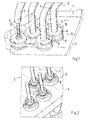
- Fig. 6 shows a second embodiment of the device for the wall lead-through of the lines 4 a wall of a body of a motor vehicle, not shown here.
- the lines 4 are again provided with line couplings, of which only the first coupling halves 6a are shown here.
- two first coupling halves 6 are by one Holder 8a combined into a group; a total of 2 holders 8a are necessary to make one out of four Lines 4 summarize existing line bundle in groups of lines 4.
- the first coupling halves 6a are through in the wall rubber-elastic plug 9 kept sealed and vibration-isolated, the present Embodiment corresponding to the first coupling halves 6a also in a group of two Stopper 9 are summarized. There is no need for groups to start from Coupling halves 6a have the same number as the group of plugs 9; the group size oriented are rather the circumstances of the assembly of the respective components.
- first coupling halves 6a there is an anti-rotation device for each of the line couplings 5 separate plug 9 is provided, each in its own opening 12 (see FIG. 3) in the wall 3 is held.
- disks 23 are rotationally fixed, for example by soldering held, the discs 23 each carry a nose 24.
- Each nose 24 engages in a corresponding one
- a recess 25 is provided in the holder 8a, so that the first coupling halves 6a in the holder 8a are held against rotation.
- FIG. 7 shows a main section through one of the first coupling halves 6a of the second Embodiment. It can be clearly seen that the nose 24 engages in the recess 25.
- the further construction of the coupling halves 6a corresponds to the first embodiment, in particular the Locking the coupling halves 6a in the holder 8a with the help of the snap ring 20 and the locking of the Coupling halves 6a in the plug 9 by circumferential lugs 16 formed on the coupling halves 6a, which engage behind a paragraph 17 provided in the plug 9.
Abstract
Description
- Fig. 1
- eine Vorderansicht einer erfindungsgemäßen Vorrichtung zur Wanddurchführung,
- Fig. 2
- eine Rückansicht der Vorrichtung zur Wanddurchführung,
- Fig. 3
- einen Schnitt nach der Ebene X der Fig. 1,
- Fig. 4
- eine Explosionsdarstellung der Vorrichtung zur Wanddurchführung ohne Wandung,
- Fig. 5
- eine Aufsicht auf einen Sprengring,
- Fig. 6
- ein zweites Ausführungsbeispiel der Vorrichtung zur Wanddurchführung,
- Fig. 7
- einen Hauptschnitt zu Fig. 6,
- Fig. 8
- eine Explosionsdarstellung von oben zu Fig. 6, und
- Fig. 9
- eine Explosionsdarstellung von unten zu Fig. 6.
Claims (4)
- Vorrichtung zur Wanddurchführung von Rohrleitungen, Schläuchen oder elektrischen Kabeln für Kraftfahrzeuge, wobei die Rohrleitungen, Schläuchen oder elektrischen Kabel im Bereich der Wanddurchführung jeweils eine Kupplung aufweisen, die Kupplung aus zwei Kupplungshälften besteht und jeweils erste Kupplungshälften in der Vorrichtung zur Wanddurchführung gemeinsam gehalten sind,
dadurch gekennzeichnet, dassjeweils wenigstens zwei erste Kupplungshälften durch eine Halterung zusammengefasst sind,Stopfen zur Aufnahme der ersten Kupplungshälften in Öffnungen einer Wandung angeordnet sind, unddie ersten Kupplungshälften in den Stopfen gehalten sind. - Vorrichtung nach Anspruch 1, dadurch gekennzeichnet, dass die Stopfen aus gummielastischem Material bestehen und in Gruppen zusammengefasst sind.
- Vorrichtung nach Anspruch 1, dadurch gekennzeichnet, dass die Stopfen einen Absatz aufweisen, der mit einem an der ersten Kupplungshälfte vorgesehenen Vorsprung rastend zusammenwirkt.
- Vorrichtung nach Anspruch 1, dadurch gekennzeichnet, dass in einer Öffnung, die in der Halterung zur Aufnahme einer ersten Kupplungshälfte vorgesehen ist, sowie in der ersten Kupplungshälfte korrespondierende Nuten vorgesehen sind, und in der in der Nut der ersten Kupplungshälfte ein Sprengring eingelegt ist.
Applications Claiming Priority (2)
| Application Number | Priority Date | Filing Date | Title |
|---|---|---|---|
| DE10233127 | 2002-07-20 | ||
| DE10233127A DE10233127C1 (de) | 2002-07-20 | 2002-07-20 | Vorrichtung zur Wanddurchführung von Rohrleitungen, Schläuchen oder elektrischen Kabeln für Kraftfahrzeuge |
Publications (3)
| Publication Number | Publication Date |
|---|---|
| EP1382894A2 true EP1382894A2 (de) | 2004-01-21 |
| EP1382894A3 EP1382894A3 (de) | 2004-03-31 |
| EP1382894B1 EP1382894B1 (de) | 2009-08-19 |
Family
ID=29432741
Family Applications (1)
| Application Number | Title | Priority Date | Filing Date |
|---|---|---|---|
| EP03009688A Expired - Lifetime EP1382894B1 (de) | 2002-07-20 | 2003-04-30 | Vorrichtung zur Wanddurchführung von Rohrleitungen, Schläuchen oder elektrischen Kabeln für Kraftfahrzeuge |
Country Status (3)
| Country | Link |
|---|---|
| US (1) | US7083202B2 (de) |
| EP (1) | EP1382894B1 (de) |
| DE (2) | DE10233127C1 (de) |
Cited By (3)
| Publication number | Priority date | Publication date | Assignee | Title |
|---|---|---|---|---|
| DE202009009807U1 (de) | 2009-07-17 | 2009-09-24 | Wiska Hoppmann & Mulsow Gmbh | Manipulationssichere Kabeldurchführung |
| EP2055535B2 (de) † | 2007-10-30 | 2014-10-22 | LEONI Bordnetz-Systeme GmbH | Kabelsatz, insbesondere ein Hochvoltkabelsatz für ein Kraftfahrzeug, sowie eine Vorrichtung zur Durchführung eines elektrischen Kabels und zur Anbindung einer Abschirmung des Kabels |
| DE102013214611A1 (de) * | 2013-07-26 | 2015-01-29 | Bayerische Motoren Werke Aktiengesellschaft | Kupplungssystem zum Ausbilden zumindest einer in einem Fahrzeug angeordneten fluidführenden Leitung |
Families Citing this family (37)
| Publication number | Priority date | Publication date | Assignee | Title |
|---|---|---|---|---|
| US7029238B1 (en) * | 1998-11-23 | 2006-04-18 | Mykrolis Corporation | Pump controller for precision pumping apparatus |
| US8172546B2 (en) | 1998-11-23 | 2012-05-08 | Entegris, Inc. | System and method for correcting for pressure variations using a motor |
| DE102004023242B4 (de) * | 2004-05-07 | 2007-06-14 | Airbus Deutschland Gmbh | Anschlußelement zum Verbinden von zwei Leitungselementen eines durch ein Trennelement zur Kabine eines Flugzeugs geführten Leitungssystems |
| US20060038074A1 (en) | 2004-05-07 | 2006-02-23 | Buhr Theo D | Connecting element for connecting a conduit system to cooling aggregates in aircraft cabins |
| DE102004033567A1 (de) * | 2004-07-09 | 2006-01-26 | Leybold Optics Gmbh | Verbingungssystem und Verfahren zur Durchführung von elektrischer Leistung und Fluid |
| WO2006057957A2 (en) | 2004-11-23 | 2006-06-01 | Entegris, Inc. | System and method for a variable home position dispense system |
| DE102005055046A1 (de) * | 2005-11-16 | 2007-05-24 | J. Eberspächer GmbH & Co. KG | Übersprecher für eine Abgasanlage |
| US8753097B2 (en) | 2005-11-21 | 2014-06-17 | Entegris, Inc. | Method and system for high viscosity pump |
| JP5339914B2 (ja) | 2005-11-21 | 2013-11-13 | インテグリス・インコーポレーテッド | 低減された形状要因を有するポンプのためのシステムと方法 |
| US7850431B2 (en) | 2005-12-02 | 2010-12-14 | Entegris, Inc. | System and method for control of fluid pressure |
| WO2007067339A2 (en) * | 2005-12-02 | 2007-06-14 | Entegris, Inc. | Fixed volume valve system |
| US8083498B2 (en) | 2005-12-02 | 2011-12-27 | Entegris, Inc. | System and method for position control of a mechanical piston in a pump |
| CN101356372B (zh) | 2005-12-02 | 2012-07-04 | 恩特格里公司 | 用于在泵中进行压力补偿的系统和方法 |
| US8025486B2 (en) | 2005-12-02 | 2011-09-27 | Entegris, Inc. | System and method for valve sequencing in a pump |
| US7878765B2 (en) | 2005-12-02 | 2011-02-01 | Entegris, Inc. | System and method for monitoring operation of a pump |
| KR20080073778A (ko) * | 2005-12-02 | 2008-08-11 | 엔테그리스, 아이엔씨. | O링 없는 로우 프로파일 피팅 및 피팅 조립체 |
| CN101356488B (zh) | 2005-12-02 | 2012-05-16 | 恩特格里公司 | 与泵控制器对接的i/o系统、方法和设备 |
| US7897196B2 (en) | 2005-12-05 | 2011-03-01 | Entegris, Inc. | Error volume system and method for a pump |
| DE102006002565A1 (de) * | 2006-01-05 | 2007-07-12 | Alfred Kärcher Gmbh & Co. Kg | Kupplungsteil für Steckverbinderanordnung |
| DE102006002564A1 (de) * | 2006-01-05 | 2007-07-12 | Alfred Kärcher Gmbh & Co. Kg | Steckteil für Steckverbinderanordnung |
| TWI402423B (zh) | 2006-02-28 | 2013-07-21 | Entegris Inc | 用於一幫浦操作之系統及方法 |
| US7494265B2 (en) * | 2006-03-01 | 2009-02-24 | Entegris, Inc. | System and method for controlled mixing of fluids via temperature |
| US7684446B2 (en) * | 2006-03-01 | 2010-03-23 | Entegris, Inc. | System and method for multiplexing setpoints |
| SE530620C2 (sv) * | 2006-12-01 | 2008-07-22 | Nordhydraulic Ab | Parkeringsorgan för hydraulisk koppling |
| SE530621C2 (sv) * | 2006-12-01 | 2008-07-22 | Nordhydraulic Ab | Hydraulisk anslutning |
| DE202007012400U1 (de) * | 2007-04-19 | 2008-08-21 | Voss Automotive Gmbh | Anschlussvorrichtung für Medienleitungen im Bereich einer Wandungsdurchführung sowie Wandungselement |
| WO2009041865A1 (en) * | 2007-09-26 | 2009-04-02 | Volvo Lastvagnar Ab | A drive unit for a heavy vehicle |
| DE102008014291A1 (de) | 2008-03-14 | 2009-09-24 | Agco Gmbh | Schwingungsentkopplungsvorrichtung für Hydraulik |
| DE202008005929U1 (de) * | 2008-04-29 | 2009-09-03 | Voss Automotive Gmbh | Anschlussvorrichtung für Medienleitungen im Bereich einer Wandungsdurchführung sowie Wandungselement |
| DE102008029468B4 (de) * | 2008-06-20 | 2011-01-13 | Airbus Operations Gmbh | Schnittstellenelement, Flugzeuginnenausstattungsbauteil und Verfahren zur Montage eines Flugzeuginnenausstattungsbauteils |
| FR2938039A1 (fr) * | 2008-10-31 | 2010-05-07 | Peugeot Citroen Automobiles Sa | Ensemble de raccordement. |
| US20110103882A1 (en) * | 2009-11-03 | 2011-05-05 | Mcdavid Bradford A | Pipe flange guide shroud |
| US8511717B2 (en) * | 2011-06-30 | 2013-08-20 | Harley-Davidson Motor Company Group, LLC | Poka-yoke for a set of hydraulic fittings |
| KR101211637B1 (ko) * | 2011-12-12 | 2012-12-18 | 주식회사 화승알앤에이 | 다방향 커넥터를 구비하는 이중관 열교환기 및 이를 구비하는 차량용 냉방 장치 |
| DE102018205611A1 (de) * | 2018-04-13 | 2019-10-17 | Volkswagen Aktiengesellschaft | Gehäuse mit einem Kabeldurchführungselement und Verfahren zur Befestigung eines Sensorkabels an einem Gehäuse einer Kraftfahrzeuglenkung |
| US11293430B2 (en) * | 2020-01-22 | 2022-04-05 | DropWater Solutions | Smart pump controller |
| US11792885B2 (en) | 2020-01-22 | 2023-10-17 | DropWater Solutions | Wireless mesh for fluid distribution network |
Citations (1)
| Publication number | Priority date | Publication date | Assignee | Title |
|---|---|---|---|---|
| DE3226475A1 (de) | 1982-07-15 | 1984-01-19 | Daimler-Benz Ag, 7000 Stuttgart | Abdichtende wanddurchfuehrung fuer rohrleitungen, schlaeuche oder elektrische kabel fuer kraftfahrzeuge |
Family Cites Families (11)
| Publication number | Priority date | Publication date | Assignee | Title |
|---|---|---|---|---|
| US3869152A (en) * | 1974-03-27 | 1975-03-04 | Gen Motors Corp | Tube mounting assembly |
| US3869153A (en) * | 1974-07-22 | 1975-03-04 | Gen Motors Corp | Double tube mounting assembly |
| US4482172A (en) * | 1981-07-09 | 1984-11-13 | Eaton Corporation | Dual sealing fluid connector |
| US4630847A (en) * | 1984-10-05 | 1986-12-23 | Colder Products Company | Multiple tube connector |
| US4893845A (en) * | 1988-04-18 | 1990-01-16 | Proprietary Technology, Inc. | Firewall heater line adapter |
| DE4138064C1 (de) * | 1991-11-19 | 1993-05-06 | Kreuzer Gmbh + Co Ohg, 8039 Puchheim, De | |
| JP3508381B2 (ja) * | 1996-04-26 | 2004-03-22 | 東海ゴム工業株式会社 | 集束ホース用ワンタッチ接続装置 |
| US5730121A (en) * | 1996-07-19 | 1998-03-24 | Hawkins, Jr.; Albert D. | Emergency air system |
| US5951059A (en) * | 1996-07-24 | 1999-09-14 | Tokai Rubber Industries Ltd. | Tube connector device having connector holder made of elastomer |
| US6520545B2 (en) * | 2000-12-08 | 2003-02-18 | Sartorius Ag | Fluid connection adapter assembly |
| US6609732B1 (en) * | 2002-02-01 | 2003-08-26 | General Motors Corporation | Quick connect multi-hose connector |
-
2002
- 2002-07-20 DE DE10233127A patent/DE10233127C1/de not_active Expired - Fee Related
-
2003
- 2003-04-30 EP EP03009688A patent/EP1382894B1/de not_active Expired - Lifetime
- 2003-04-30 DE DE50311821T patent/DE50311821D1/de not_active Expired - Lifetime
- 2003-07-21 US US10/622,643 patent/US7083202B2/en not_active Expired - Lifetime
Patent Citations (1)
| Publication number | Priority date | Publication date | Assignee | Title |
|---|---|---|---|---|
| DE3226475A1 (de) | 1982-07-15 | 1984-01-19 | Daimler-Benz Ag, 7000 Stuttgart | Abdichtende wanddurchfuehrung fuer rohrleitungen, schlaeuche oder elektrische kabel fuer kraftfahrzeuge |
Cited By (4)
| Publication number | Priority date | Publication date | Assignee | Title |
|---|---|---|---|---|
| EP2055535B2 (de) † | 2007-10-30 | 2014-10-22 | LEONI Bordnetz-Systeme GmbH | Kabelsatz, insbesondere ein Hochvoltkabelsatz für ein Kraftfahrzeug, sowie eine Vorrichtung zur Durchführung eines elektrischen Kabels und zur Anbindung einer Abschirmung des Kabels |
| DE202009009807U1 (de) | 2009-07-17 | 2009-09-24 | Wiska Hoppmann & Mulsow Gmbh | Manipulationssichere Kabeldurchführung |
| DE102010031345A1 (de) | 2009-07-17 | 2011-01-20 | Wiska Hoppmann & Mulsow Gmbh | Manipulationssichere Kabeldurchführung |
| DE102013214611A1 (de) * | 2013-07-26 | 2015-01-29 | Bayerische Motoren Werke Aktiengesellschaft | Kupplungssystem zum Ausbilden zumindest einer in einem Fahrzeug angeordneten fluidführenden Leitung |
Also Published As
| Publication number | Publication date |
|---|---|
| US20040037627A1 (en) | 2004-02-26 |
| EP1382894B1 (de) | 2009-08-19 |
| DE50311821D1 (de) | 2009-10-01 |
| US7083202B2 (en) | 2006-08-01 |
| DE10233127C1 (de) | 2003-12-11 |
| EP1382894A3 (de) | 2004-03-31 |
Similar Documents
| Publication | Publication Date | Title |
|---|---|---|
| DE10233127C1 (de) | Vorrichtung zur Wanddurchführung von Rohrleitungen, Schläuchen oder elektrischen Kabeln für Kraftfahrzeuge | |
| EP3329566B1 (de) | Explosionsgeschützte anordnung und verfahren zu deren herstellung | |
| WO2016141921A1 (de) | Kabelabdichtung | |
| DE4434202A1 (de) | Kabeldurchführungsleiste | |
| EP1134472B1 (de) | Dichtungselement für eine Vorrichtung zur brandgesicherten Durchführung von Leitungen u.dgl. durch in Wänden befindliche Öffnungen hindurch | |
| DE102010017266A1 (de) | Elektrische Verteilereinrichtung | |
| DE102015007404A1 (de) | Leitungsaufnehmer | |
| DE102015112284A1 (de) | Explosionsgeschützte Anordnung und Verfahren zu deren Herstellung | |
| EP1867024A1 (de) | Leitungsdurchführungsvorrichtung | |
| DE102006043575B3 (de) | Solarsteckverbinder mit einem Kabeladapter zur Anpassung an Kabel mit unterschiedlichen Durchmessern | |
| EP2447583B1 (de) | Dichtvorrichtung | |
| EP2735058B1 (de) | Kabelanschlussbauteil | |
| EP2688169A1 (de) | Kabeldurchführung | |
| WO2012045430A2 (de) | Kabelabschlusseinrichtung | |
| EP0695008B1 (de) | Universelle Kabelklemmvorrichtung | |
| DE10349440B4 (de) | Dichte Wanddurchführung mit Zugentlastung | |
| EP1289087A2 (de) | Verschluss- und Abdichtelement | |
| DE19908657C1 (de) | Vorrichtung zum Abdecken und Abdichten eines Kabeldurchführungsdurchbruches in einer Wand eines Schaltschrankes | |
| DE102014012335A1 (de) | Elektrisches Gerät | |
| CH710076B1 (de) | Rahmenvorrichtung für eine Fasermanagementeinheit. | |
| EP1484544A1 (de) | Leitungsdurchführung für die Installation von einer durch eine Wand hindurchführende Sanitärleitung | |
| DE102016104477A1 (de) | Brauseschlauch | |
| DE102008011978A1 (de) | Verschraubung für abgedichtete Leitungsdurchführungen | |
| EP0584616A2 (de) | Anordnung für Mehrfachkabeleinführungen bei Kabelmuffen | |
| DE19743185A1 (de) | Vorrichtung zum Anschließen von Rohrleitungen |
Legal Events
| Date | Code | Title | Description |
|---|---|---|---|
| PUAI | Public reference made under article 153(3) epc to a published international application that has entered the european phase |
Free format text: ORIGINAL CODE: 0009012 |
|
| AK | Designated contracting states |
Kind code of ref document: A2 Designated state(s): AT BE BG CH CY CZ DE DK EE ES FI FR GB GR HU IE IT LI LU MC NL PT RO SE SI SK TR |
|
| AX | Request for extension of the european patent |
Extension state: AL LT LV MK |
|
| PUAL | Search report despatched |
Free format text: ORIGINAL CODE: 0009013 |
|
| RIC1 | Information provided on ipc code assigned before grant |
Ipc: 7F 16L 5/08 B Ipc: 7F 16L 5/02 A Ipc: 7F 16L 5/06 B |
|
| AK | Designated contracting states |
Kind code of ref document: A3 Designated state(s): AT BE BG CH CY CZ DE DK EE ES FI FR GB GR HU IE IT LI LU MC NL PT RO SE SI SK TR |
|
| AX | Request for extension of the european patent |
Extension state: AL LT LV MK |
|
| 17P | Request for examination filed |
Effective date: 20040930 |
|
| AKX | Designation fees paid |
Designated state(s): DE ES FR GB IT SE |
|
| 17Q | First examination report despatched |
Effective date: 20071016 |
|
| RAP1 | Party data changed (applicant data changed or rights of an application transferred) |
Owner name: DR. ING. H.C. F. PORSCHE AKTIENGESELLSCHAFT |
|
| RAP1 | Party data changed (applicant data changed or rights of an application transferred) |
Owner name: DR. ING. H.C. F. PORSCHE AKTIENGESELLSCHAFT |
|
| GRAC | Information related to communication of intention to grant a patent modified |
Free format text: ORIGINAL CODE: EPIDOSCIGR1 |
|
| GRAP | Despatch of communication of intention to grant a patent |
Free format text: ORIGINAL CODE: EPIDOSNIGR1 |
|
| GRAS | Grant fee paid |
Free format text: ORIGINAL CODE: EPIDOSNIGR3 |
|
| GRAA | (expected) grant |
Free format text: ORIGINAL CODE: 0009210 |
|
| AK | Designated contracting states |
Kind code of ref document: B1 Designated state(s): DE ES FR GB IT SE |
|
| REG | Reference to a national code |
Ref country code: GB Ref legal event code: FG4D Free format text: NOT ENGLISH |
|
| REF | Corresponds to: |
Ref document number: 50311821 Country of ref document: DE Date of ref document: 20091001 Kind code of ref document: P |
|
| PG25 | Lapsed in a contracting state [announced via postgrant information from national office to epo] |
Ref country code: SE Free format text: LAPSE BECAUSE OF FAILURE TO SUBMIT A TRANSLATION OF THE DESCRIPTION OR TO PAY THE FEE WITHIN THE PRESCRIBED TIME-LIMIT Effective date: 20090819 Ref country code: ES Free format text: LAPSE BECAUSE OF FAILURE TO SUBMIT A TRANSLATION OF THE DESCRIPTION OR TO PAY THE FEE WITHIN THE PRESCRIBED TIME-LIMIT Effective date: 20091130 |
|
| PLBE | No opposition filed within time limit |
Free format text: ORIGINAL CODE: 0009261 |
|
| STAA | Information on the status of an ep patent application or granted ep patent |
Free format text: STATUS: NO OPPOSITION FILED WITHIN TIME LIMIT |
|
| 26N | No opposition filed |
Effective date: 20100520 |
|
| GBPC | Gb: european patent ceased through non-payment of renewal fee |
Effective date: 20100430 |
|
| REG | Reference to a national code |
Ref country code: FR Ref legal event code: TP |
|
| PG25 | Lapsed in a contracting state [announced via postgrant information from national office to epo] |
Ref country code: IT Free format text: LAPSE BECAUSE OF FAILURE TO SUBMIT A TRANSLATION OF THE DESCRIPTION OR TO PAY THE FEE WITHIN THE PRESCRIBED TIME-LIMIT Effective date: 20090819 Ref country code: GB Free format text: LAPSE BECAUSE OF NON-PAYMENT OF DUE FEES Effective date: 20100430 |
|
| PGFP | Annual fee paid to national office [announced via postgrant information from national office to epo] |
Ref country code: FR Payment date: 20110510 Year of fee payment: 9 |
|
| REG | Reference to a national code |
Ref country code: FR Ref legal event code: ST Effective date: 20121228 |
|
| PG25 | Lapsed in a contracting state [announced via postgrant information from national office to epo] |
Ref country code: FR Free format text: LAPSE BECAUSE OF NON-PAYMENT OF DUE FEES Effective date: 20120430 |
|
| PGFP | Annual fee paid to national office [announced via postgrant information from national office to epo] |
Ref country code: DE Payment date: 20160405 Year of fee payment: 14 |
|
| REG | Reference to a national code |
Ref country code: DE Ref legal event code: R119 Ref document number: 50311821 Country of ref document: DE |
|
| PG25 | Lapsed in a contracting state [announced via postgrant information from national office to epo] |
Ref country code: DE Free format text: LAPSE BECAUSE OF NON-PAYMENT OF DUE FEES Effective date: 20171103 |