EP1383344B1 - Measurement of blurring in video sequences - Google Patents
Measurement of blurring in video sequences Download PDFInfo
- Publication number
- EP1383344B1 EP1383344B1 EP03254657A EP03254657A EP1383344B1 EP 1383344 B1 EP1383344 B1 EP 1383344B1 EP 03254657 A EP03254657 A EP 03254657A EP 03254657 A EP03254657 A EP 03254657A EP 1383344 B1 EP1383344 B1 EP 1383344B1
- Authority
- EP
- European Patent Office
- Prior art keywords
- video sequence
- blurring
- edge
- test video
- frame
- Prior art date
- Legal status (The legal status is an assumption and is not a legal conclusion. Google has not performed a legal analysis and makes no representation as to the accuracy of the status listed.)
- Expired - Lifetime
Links
- 238000005259 measurement Methods 0.000 title description 15
- 238000012360 testing method Methods 0.000 claims abstract description 41
- 238000012545 processing Methods 0.000 claims abstract description 12
- 238000000034 method Methods 0.000 claims abstract description 11
- 238000013139 quantization Methods 0.000 claims description 14
- 238000001914 filtration Methods 0.000 claims description 6
- 230000007704 transition Effects 0.000 claims description 5
- 238000013459 approach Methods 0.000 description 8
- 238000011156 evaluation Methods 0.000 description 7
- 238000007906 compression Methods 0.000 description 4
- 230000001771 impaired effect Effects 0.000 description 4
- 230000006835 compression Effects 0.000 description 3
- 230000000903 blocking effect Effects 0.000 description 2
- 238000004364 calculation method Methods 0.000 description 2
- 230000001419 dependent effect Effects 0.000 description 2
- 238000001514 detection method Methods 0.000 description 2
- 238000010586 diagram Methods 0.000 description 2
- 238000012986 modification Methods 0.000 description 2
- 230000004048 modification Effects 0.000 description 2
- 230000000007 visual effect Effects 0.000 description 2
- 238000012935 Averaging Methods 0.000 description 1
- 238000007476 Maximum Likelihood Methods 0.000 description 1
- 238000004458 analytical method Methods 0.000 description 1
- 238000005311 autocorrelation function Methods 0.000 description 1
- 230000000694 effects Effects 0.000 description 1
- 230000008030 elimination Effects 0.000 description 1
- 238000003379 elimination reaction Methods 0.000 description 1
- 238000010191 image analysis Methods 0.000 description 1
- 238000007689 inspection Methods 0.000 description 1
- 238000007781 pre-processing Methods 0.000 description 1
- 230000008569 process Effects 0.000 description 1
- 238000013442 quality metrics Methods 0.000 description 1
- 238000001228 spectrum Methods 0.000 description 1
- 230000007480 spreading Effects 0.000 description 1
Images


Classifications
-
- H—ELECTRICITY
- H04—ELECTRIC COMMUNICATION TECHNIQUE
- H04N—PICTORIAL COMMUNICATION, e.g. TELEVISION
- H04N17/00—Diagnosis, testing or measuring for television systems or their details
-
- H—ELECTRICITY
- H04—ELECTRIC COMMUNICATION TECHNIQUE
- H04N—PICTORIAL COMMUNICATION, e.g. TELEVISION
- H04N17/00—Diagnosis, testing or measuring for television systems or their details
- H04N17/004—Diagnosis, testing or measuring for television systems or their details for digital television systems
-
- H—ELECTRICITY
- H04—ELECTRIC COMMUNICATION TECHNIQUE
- H04N—PICTORIAL COMMUNICATION, e.g. TELEVISION
- H04N5/00—Details of television systems
- H04N5/14—Picture signal circuitry for video frequency region
- H04N5/20—Circuitry for controlling amplitude response
- H04N5/205—Circuitry for controlling amplitude response for correcting amplitude versus frequency characteristic
- H04N5/208—Circuitry for controlling amplitude response for correcting amplitude versus frequency characteristic for compensating for attenuation of high frequency components, e.g. crispening, aperture distortion correction
-
- H—ELECTRICITY
- H04—ELECTRIC COMMUNICATION TECHNIQUE
- H04N—PICTORIAL COMMUNICATION, e.g. TELEVISION
- H04N5/00—Details of television systems
- H04N5/14—Picture signal circuitry for video frequency region
- H04N5/21—Circuitry for suppressing or minimising disturbance, e.g. moiré or halo
Definitions
- the present invention relates to video quality of service, and more particularly to the measurement of blurring in video sequences due to video processing.
- DCT block Discrete Cosine Transform
- noise originated from quantization of DCT components is not independent in the spatial domain, but contributes to blocking errors and high frequency noise around edges.
- Blur distortion in MPEG and H.263 video sequences is caused by DCT quantization. When the quantization truncates the high frequency DCT coefficients completely, the loss appears as blur in the video sequence. Because quantization level changes across block boundaries, the resulting blur as well as quantization noise vary accordingly.
- a single-ended blur estimation scheme was proposed by Jiuhuai Lu in the Proceedings SPIE 4301 - Machine Vision Applications in Industrial Inspection - San Jose, California, January 2001 in a paper entitled "Image Analysis for Video Artifact Estimation and Measurement ".
- the scheme has several steps, including pre-processing to eliminate artifacts that produce spurious edges, evaluation point selection to choose appropriate places for blur estimation, blur estimating at each selected evaluation point and averaging to provide a frame-based blur estimate.
- edges of blocking boundaries may be reduced by simple lowpass filtering.
- the evaluation point selection determines a set of image edge points on the basis of edge intensity and connectivity to eliminate blurring due to other than quantization in compression.
- a statistical approach is used to estimate the extent of picture blur by extracting an edge profile spread at the selected edge points using a norm of the edge gradient as follows:
- the edge profile p is centered at point (x,y) being evaluated and is equally spaced.
- An autocorrelation of the edge profile is obtained and used to obtain the edge profile spread.
- the edge profile is corrected if it has a tilted baseline before computing the autocorrelation function.
- the blur estimation of the video picture or frame is the average of the edge profile spread at all chosen evaluation points.
- an apparatus for estimating blurring due to video processing as claimed in claim 5.
- the present invention provides for measurement of blurring in video sequences by filtering a test video sequence with both an edge definition filter and an edge enhancement filter.
- the output from the edge definition filter together with block size information is used to determine those blocks within each frame of the test video sequence that contain a valid image edge.
- the output from the edge enhancement filter together with the block size information is used with the valid image edge blocks to select edge points. Normals to the valid image edges at the edge points as a function of the edge enhancement filter output are used to estimate a blurring value for each frame of the test video sequence.
- a reference blurring value is generated from a reference video sequence corresponding to the test video sequence, the reference blurring value either being generated at a source and transmitted with the test video sequence or being generated at a receiver together with the test video sequence.
- the reference blurring value is compared with the blurring value for the test video sequence to determine a relative blurring value.
- Fig. 1 is a block diagram view of a single-ended blurring estimation algorithm according to the present invention.
- Fig. 2 is a graphic view illustrating the selection of valid blocks within a video frame for applying the blurring estimation algorithm according to the present invention.
- Fig. 3 is a graphic view illustrating the selection of valid edge points within a selected block for applying the blurring estimation algorithm according to the present invention.
- Fig. 4 is a block diagram view of a double-ended blurring estimation algorithm according to the present invention.
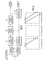
- Fig. 5 is a plan view of a blurring map output showing blurring value over time/frame number for a blurred frame according to the present invention.
- Fig. 6 is a plan view of a blurring map output showing blurring value over time/frame number for a compressed frame according to the present invention.
- Fig. 7 is a graphic view of single-ended blur values for two different video sequences with increasing blurring artifacts introduced as achieved according to the present invention.
- the luminance component (Y) of a test video image is input to both an edge definition filter, such as a Canny filter 12 , and an edge enhancement filter, such as a Sobel filter 14 .
- the Canny filter 12 produces a map having zeros at all points except edge points, which are ones.
- the Sobel filter 14 provides edge enhancement with values varying between zero and one (normalized).
- the output from the Canny filter 12 is input to a detector block 16 for finding valid "edge" blocks, i.e., quantization blocks or predetermined blocks that have a bona fide image edge.
- the output from the Sobel filter 14 is input to a blockiness removal block 18 for removing edges that are related to quantization blocks for compressed video sequences, i.e., are not bona fide image edges. Also input to the detector block 16 and the blockiness removal block 18 is information about the size of the blocks and any offset required for spatial alignment, if necessary.
- the outputs from the detector and blockiness removal blocks 16 , 18 are input to a selector block 20 for selecting valid image edge points.
- the output from the blockiness removal block 18 also is input to a map generator 22 .
- the output from the selector block 20 is input to a blur calculation block 24 which provides a blurring value, either on a frame basis or on a video sequence basis or both.
- the blurring value also is input to the map generator 22 to produce a weighted blurring map for display.
- the basic idea is to find the strongest edges and/or lines in an image, or frame, of a video sequence, then to look at the edge profile at these points to see how spread the edges are, thus giving an indication of the blurring of the image. Large spreading at these points indicates that the frame is strongly blurred, while a narrow spread suggests that the image is sharp.
- Both the luminance frame (Y) and the blockiness size and any offset are inputs.
- the blockiness information allows the removal of quantization block boundaries, where appropriate, so that only true image edges are used and provides a scaling in which blocks containing valid image edges may be found.
- the blockiness size and offset may be either directly obtained from information in a decoder, or by running a blockiness detection algorithm, such as that described in U.S. Patent Application Serial No.
- the removal of edges in the blockiness removal block 18 may be achieved by replacing the output from the Sobel filter 14 at block boundaries with a Sobel output interpolated from nearest neighbors.
- the detection of blocks that contain valid image edges uses the output from the Canny filter 12 as shown in Fig. 2 .
- the image is divided into individual blocks, using either the default block size or the block size determined by the blockiness size and offset input.
- a block is classed as containing an image edge if the number of transitions from zero to one around the boundary of the block equals two, as shown in Fig. 2 at A.
- Blocks that contain more that two transitions, such as shown at C are likely to be textures, and therefore not so useful for blurring estimation, while blocks with less than two transitions, such as B, are likely to be flat, also inappropriate for blurring estimation.
- Each valid block from the selection block 16 is further tested as shown in Fig. 3 to detect valid edge points that may be used for the blurriness estimation.
- the (x,y) location of a peak value of the Sobel edge map with blockiness removed within a "safe", i.e., central, area of each valid block is determined.
- the peak Sobel value is denoted S(0).
- the direction of the edge at this point is calculated from the x and y outputs of the Sobel edge map at this point.
- the profile of the edge is then taken normal to the edge direction.
- a number of points N typically 3-4 on either side of the valid point, are interpolated using a weighted four-point interpolation.
- S(-N)... S(N) form the profile of the edge centered at point (0).
- Blurring values for an entire video sequence or a specific section of the video sequence may also be calculated.
- the mean of the frame blurring values provides a good indication of sequence blurring.
- Other more complex methods, such as Minkowski summation or min-max calculation, may also be used.
- a blurring map is also provided.
- the blurring map indicates the areas in the image where the blurring is most visible. It is obtained by weighting the blockiness removed Sobel map with the frame blurring measure. Either a linear or a non-linear weighting may be used, depending upon the application for which the map is used. The linear weighting has been tested successfully, as shown in Fig. 5 , for blurring in an uncompressed video image.
- Fig. 6 is a corresponding view of blurring in a compressed video image.
- the non-linear weighting may be achieved in a number of ways, such as by using a non-linear "S" curve or by performing a local weighting near the valid points based on the estimated strength of the edge at each valid point.
- a reduced-reference blurring measurement works in a very similar way to the single-ended blurring measurement described above.
- the single-ended blurring is calculated on a reference frame, with the resulting blurring value being passed along with a test frame, perhaps using a different channel or the video header.
- the single-ended measurement is performed on the test frame to produce a test blurring value.
- the test blurring value is compared with the reference blurring value in order to determine the amount of blurring introduced into the test frame.
- both linear and non-linear methods may be used to perform this comparison. A simple subtraction of the reference and test blurring values provides good results.
- double-ended blurring measurement may be performed by performing separate single-ended measurements on both the reference and test videos and then comparing the results.
- An alternative is to perfrom the Canny filtering and valid edge block selection using the reference video only. This approach offers computational as well as potential accuracy improvements. Further modifications may also be made, such as using the same valid edge points for both the reference and test frames prior to the blurring estimation. Since the double-ended measurement provides a relative estimate of the blurring between the reference and test videos, this approach is typically more consistent across different types of video since it is not as source dependent as the single-ended approach.
- the reference luminance frame (Y_ref) is input to the Canny filter 12 while the test or impaired luminance frame (Y_imp) is input to the Sobel filter 14 .
- the selection of valid image edge blocks by the selection block 16 is determined by Y_ref and the blockiness size and offset information, while the impaired Sobel edge map from the blockiness removal block 18 is determined by Y_imp and the blockiness size and offset information.
- the determination of valid edge points, the frame blurring estimation and the weighted blurring map are computed as in the single-ended approach for both Y_ref and Y_imp, with the Y_ref output from the Sobel filter 14 bypassing the blockiness removal block 18 , as indicated by the dotted lines.
- comparison block 26 that compares the reference blurring value with the impaired blurring value to determine a relative blurring estimate.
- Fig. 7 shows the results produced by the present invention when blurring is gradually introduced over a period of time/frames for two different video sequences.
- the present invention provides a blurring measurement for a video sequence by selecting blocks in the image that have valid edges based on a Canny filtered output for the video sequence and removing block boundaries from the video sequence using a Sobel filter, by selecting valid edge points centrally located within the selected valid edge blocks, by estimating spread normal to the edge, and by determining an average for the image or sequence or portion of sequence based on histograms of the estimated spread. Also a blurring map is generated from the block boundary corrected Sobel output weighted by the blurring estimate.
Abstract
Description
- The present invention relates to video quality of service, and more particularly to the measurement of blurring in video sequences due to video processing.
- A number of different factors influence the visual quality of a digital video sequence. Numerous subjective studies have shown that the amount of blurring in the video sequence is one of the factors that has the strongest influence on overall visual quality. Therefore the ability to objectively measure the amount of blurring in the video sequence is a key element in a video quality metric. A codec developer or compression service provider may use this information to modify the compression process and make informed decisions regarding the various tradeoffs needed to deliver quality digital video services.
- Although studies have been done in blur identification, most blur identification approaches, such as spectrum, bispectrum and maximum likelihood based approaches, were developed under the assumption of uniform blur or under the restriction of only tolerating the existence of white Gaussian noise. The blurring effect resulting from block Discrete Cosine Transform (DCT) based compression may vary from one block to another due to different quantization parameters used for coding different macroblocks. Additionally noise originated from quantization of DCT components is not independent in the spatial domain, but contributes to blocking errors and high frequency noise around edges. Blur distortion in MPEG and H.263 video sequences is caused by DCT quantization. When the quantization truncates the high frequency DCT coefficients completely, the loss appears as blur in the video sequence. Because quantization level changes across block boundaries, the resulting blur as well as quantization noise vary accordingly.
- A single-ended blur estimation scheme was proposed by Jiuhuai Lu in the Proceedings SPIE 4301 - Machine Vision Applications in Industrial Inspection - San Jose, California, January 2001 in a paper entitled "Image Analysis for Video Artifact Estimation and Measurement". The scheme has several steps, including pre-processing to eliminate artifacts that produce spurious edges, evaluation point selection to choose appropriate places for blur estimation, blur estimating at each selected evaluation point and averaging to provide a frame-based blur estimate. For blur estimation edges of blocking boundaries may be reduced by simple lowpass filtering. The evaluation point selection determines a set of image edge points on the basis of edge intensity and connectivity to eliminate blurring due to other than quantization in compression. Finally a statistical approach is used to estimate the extent of picture blur by extracting an edge profile spread at the selected edge points using a norm of the edge gradient as follows:
- 1) compute the gradient vector at the current evaluation point,
- 2) sample the edge image e(x,y) along both sides of the gradient vector centered at the evaluation point,
- 3) set the data series of the sampled edge values as the edge profile at the evaluation point,
- 4) compute the edge profile spread.
- The edge profile p is centered at point (x,y) being evaluated and is equally spaced. An autocorrelation of the edge profile is obtained and used to obtain the edge profile spread. The edge profile is corrected if it has a tilted baseline before computing the autocorrelation function. The blur estimation of the video picture or frame is the average of the edge profile spread at all chosen evaluation points. This disclosed technique is general and does not provide specific details for providing an accurate and robust measurement, and only applies to single-ended applications, not to double-ended or reduced-reference applications.
- What is desired is to provide an accurate, robust, repeatable and computationally feasible method of measuring blurring in video sequences for use in any application that requires video quality measurement.
- According to a first aspect of the invention, there is provided a method of estimating blurring due to video processing as claimed in
claim 1. - According to a second aspect of the invention, there is provided an apparatus for estimating blurring due to video processing, as claimed in claim 5.
- Further embodiments of the invention are included in the dependent claims.
- Accordingly the present invention provides for measurement of blurring in video sequences by filtering a test video sequence with both an edge definition filter and an edge enhancement filter. The output from the edge definition filter together with block size information is used to determine those blocks within each frame of the test video sequence that contain a valid image edge. The output from the edge enhancement filter together with the block size information, after elimination of block boundary edges induced by video processing if appropriate, is used with the valid image edge blocks to select edge points. Normals to the valid image edges at the edge points as a function of the edge enhancement filter output are used to estimate a blurring value for each frame of the test video sequence.
- For reduced-reference or full reference applications a reference blurring value is generated from a reference video sequence corresponding to the test video sequence, the reference blurring value either being generated at a source and transmitted with the test video sequence or being generated at a receiver together with the test video sequence. The reference blurring value is compared with the blurring value for the test video sequence to determine a relative blurring value.
- The objects, advantages and other novel features of the present invention are apparent from the following detailed description when read in conjunction with the appended claims and attached drawing.
-
Fig. 1 is a block diagram view of a single-ended blurring estimation algorithm according to the present invention. -
Fig. 2 is a graphic view illustrating the selection of valid blocks within a video frame for applying the blurring estimation algorithm according to the present invention. -
Fig. 3 is a graphic view illustrating the selection of valid edge points within a selected block for applying the blurring estimation algorithm according to the present invention. -
Fig. 4 is a block diagram view of a double-ended blurring estimation algorithm according to the present invention. -
Fig. 5 is a plan view of a blurring map output showing blurring value over time/frame number for a blurred frame according to the present invention. -
Fig. 6 is a plan view of a blurring map output showing blurring value over time/frame number for a compressed frame according to the present invention. -
Fig. 7 is a graphic view of single-ended blur values for two different video sequences with increasing blurring artifacts introduced as achieved according to the present invention. - Referring to
Fig. 1 for a single-ended measurement of blurring the luminance component (Y) of a test video image is input to both an edge definition filter, such as a Cannyfilter 12, and an edge enhancement filter, such as aSobel filter 14. The Cannyfilter 12 produces a map having zeros at all points except edge points, which are ones. The Sobelfilter 14 provides edge enhancement with values varying between zero and one (normalized). The output from the Cannyfilter 12 is input to adetector block 16 for finding valid "edge" blocks, i.e., quantization blocks or predetermined blocks that have a bona fide image edge. The output from the Sobelfilter 14 is input to ablockiness removal block 18 for removing edges that are related to quantization blocks for compressed video sequences, i.e., are not bona fide image edges. Also input to thedetector block 16 and theblockiness removal block 18 is information about the size of the blocks and any offset required for spatial alignment, if necessary. The outputs from the detector andblockiness removal blocks selector block 20 for selecting valid image edge points. The output from theblockiness removal block 18 also is input to amap generator 22. The output from theselector block 20 is input to ablur calculation block 24 which provides a blurring value, either on a frame basis or on a video sequence basis or both. The blurring value also is input to themap generator 22 to produce a weighted blurring map for display. - The basic idea is to find the strongest edges and/or lines in an image, or frame, of a video sequence, then to look at the edge profile at these points to see how spread the edges are, thus giving an indication of the blurring of the image. Large spreading at these points indicates that the frame is strongly blurred, while a narrow spread suggests that the image is sharp. Both the luminance frame (Y) and the blockiness size and any offset are inputs. The blockiness information allows the removal of quantization block boundaries, where appropriate, so that only true image edges are used and provides a scaling in which blocks containing valid image edges may be found. The blockiness size and offset may be either directly obtained from information in a decoder, or by running a blockiness detection algorithm, such as that described in
U.S. Patent Application Serial No. 09/152,495 filed September 10, 1998 selector block 16. - The removal of edges in the
blockiness removal block 18 may be achieved by replacing the output from the Sobelfilter 14 at block boundaries with a Sobel output interpolated from nearest neighbors. The detection of blocks that contain valid image edges uses the output from the Cannyfilter 12 as shown inFig. 2 . The image is divided into individual blocks, using either the default block size or the block size determined by the blockiness size and offset input. A block is classed as containing an image edge if the number of transitions from zero to one around the boundary of the block equals two, as shown inFig. 2 at A. Blocks that contain more that two transitions, such as shown at C, are likely to be textures, and therefore not so useful for blurring estimation, while blocks with less than two transitions, such as B, are likely to be flat, also inappropriate for blurring estimation. - Each valid block from the
selection block 16 is further tested as shown inFig. 3 to detect valid edge points that may be used for the blurriness estimation. The (x,y) location of a peak value of the Sobel edge map with blockiness removed within a "safe", i.e., central, area of each valid block is determined. The peak Sobel value is denoted S(0). The direction of the edge at this point is calculated from the x and y outputs of the Sobel edge map at this point. The profile of the edge is then taken normal to the edge direction. Along a line normal to the edge direction from the Sobel outputs a number of points N, typically 3-4 on either side of the valid point, are interpolated using a weighted four-point interpolation. This interpolation is necessary since the normal to the gradient generally does not coincide exactly with integer pixel coordinates. The values S(-N)... S(N) form the profile of the edge centered at point (0). The edge profile is normalized to produce Snorm as follows:

- An objective way of determining the spread of Snorm is required. An autocorrelation on Snorm to give Rnorm works successfully. This autocorrelation Rnorm is scaled so that the sum of its coefficients is equal to one. The spread Sp is then calculated by weighting the coefficients Rnorm proportional to the square of their distance from a weighted central location Pprod.


- To calculate the blurring value for an entire image or frame, a histogram of Sp values is taken, and a pth highest percentile is used to indicate the average amount of blurring for the image or frame. Values of p = 40-50% provide good results.
- Blurring values for an entire video sequence or a specific section of the video sequence may also be calculated. The mean of the frame blurring values provides a good indication of sequence blurring. Other more complex methods, such as Minkowski summation or min-max calculation, may also be used.
- As well as outputting a blurring value for each frame, a blurring map is also provided. The blurring map indicates the areas in the image where the blurring is most visible. It is obtained by weighting the blockiness removed Sobel map with the frame blurring measure. Either a linear or a non-linear weighting may be used, depending upon the application for which the map is used. The linear weighting has been tested successfully, as shown in
Fig. 5 , for blurring in an uncompressed video image.Fig. 6 is a corresponding view of blurring in a compressed video image.Figs. 5 and6 in the upper quadrants show the reference and test video images, in the lower left quadrant show the blurring values over time/frame numbers, and in the lower right quadrant show the blurring map with the valid edge points. The non-linear weighting may be achieved in a number of ways, such as by using a non-linear "S" curve or by performing a local weighting near the valid points based on the estimated strength of the edge at each valid point. - A reduced-reference blurring measurement works in a very similar way to the single-ended blurring measurement described above. The single-ended blurring is calculated on a reference frame, with the resulting blurring value being passed along with a test frame, perhaps using a different channel or the video header. At a receiver the single-ended measurement is performed on the test frame to produce a test blurring value. The test blurring value is compared with the reference blurring value in order to determine the amount of blurring introduced into the test frame. Once again both linear and non-linear methods may be used to perform this comparison. A simple subtraction of the reference and test blurring values provides good results.
- Some slight modifications may be performed when performing double-ended blurring measurement, as shown in
Fig. 4 . In its simplest form the double-ended measurement may be made by performing separate single-ended measurements on both the reference and test videos and then comparing the results. An alternative is to perfrom the Canny filtering and valid edge block selection using the reference video only. This approach offers computational as well as potential accuracy improvements. Further modifications may also be made, such as using the same valid edge points for both the reference and test frames prior to the blurring estimation. Since the double-ended measurement provides a relative estimate of the blurring between the reference and test videos, this approach is typically more consistent across different types of video since it is not as source dependent as the single-ended approach. - Therefore as shown in
Fig. 4 the reference luminance frame (Y_ref) is input to theCanny filter 12 while the test or impaired luminance frame (Y_imp) is input to theSobel filter 14. The selection of valid image edge blocks by theselection block 16 is determined by Y_ref and the blockiness size and offset information, while the impaired Sobel edge map from theblockiness removal block 18 is determined by Y_imp and the blockiness size and offset information. The determination of valid edge points, the frame blurring estimation and the weighted blurring map are computed as in the single-ended approach for both Y_ref and Y_imp, with the Y_ref output from theSobel filter 14 bypassing theblockiness removal block 18, as indicated by the dotted lines. What is added is acomparison block 26 that compares the reference blurring value with the impaired blurring value to determine a relative blurring estimate. With the double-ended approach artistic blurring is accounted for so that only undesired blurring due to video processing of the reference video to produce the impaired video is measured. - Finally
Fig. 7 shows the results produced by the present invention when blurring is gradually introduced over a period of time/frames for two different video sequences. - Thus the present invention provides a blurring measurement for a video sequence by selecting blocks in the image that have valid edges based on a Canny filtered output for the video sequence and removing block boundaries from the video sequence using a Sobel filter, by selecting valid edge points centrally located within the selected valid edge blocks, by estimating spread normal to the edge, and by determining an average for the image or sequence or portion of sequence based on histograms of the estimated spread. Also a blurring map is generated from the block boundary corrected Sobel output weighted by the blurring estimate.
Claims (5)
- A method of estimating blurring due to video processing in a test video sequence comprising the steps of:filtering (12) each frame of the test video sequence to produce a filtered output having either a zero or a one at each pixel location within each frame with the ones identifying an edge;detecting (16) quantization or predetermined blocks within each frame of the test video sequence that have two transitions from zero to one of the filtered output around a boundary of the block as having a valid image edge;selecting (20) an edge point centrally located within each detected block as a function of an edge enhanced version of the test video sequence without video processing induced quantization block boundary edges; andestimating (24) a blurring value for the test video sequence in a direction normal to a direction of the valid image edges at the edge points.
- The method as recited in claim 1 further comprising a step of generating (22) a blurring map from the edge enhanced version of the test video sequence without video processing induced block boundary edges and the blurring value.
- The method as recited in claim 1 further comprising the step of comparing (26) the blurring value with a reference blurring value for a reference video sequence transmitted with the test video sequence to obtain a relative blurring value for the test video sequence.
- The method as recited in claim 1 further comprising the steps of:repeating the filtering detecting, selecting and estimating steps for a reference video sequence corresponding to the test video sequence to produce a reference blurring value; andcomparing the blurring value with the reference blurring value to obtain a relative blurring value for the test video sequence.
- An apparatus for estimating blurring due to video processing in a test video sequence characterized by:means (12) for filtering each frame of the test video sequence to produce a filtered output having either a zero or a one at each pixel location within each frame with the ones identifying an edge;means (16) for detecting quantization or predetermined blocks within each frame of the test video sequence that have two transitions from zero to one of the filtered output around a boundary of a block as blocks having a valid image edge;means (20) for selecting an edge point centrally located within each detected block as a function of an edge enhanced version of the test video sequence without video processing induced quantization block boundary edges; andmeans (24) for estimating a blurring value for the test video sequence in a direction normal to a direction of the valid image edges at the edge points.
Applications Claiming Priority (2)
| Application Number | Priority Date | Filing Date | Title |
|---|---|---|---|
| US198944 | 2002-07-18 | ||
| US10/198,944 US7099518B2 (en) | 2002-07-18 | 2002-07-18 | Measurement of blurring in video sequences |
Publications (3)
| Publication Number | Publication Date |
|---|---|
| EP1383344A2 EP1383344A2 (en) | 2004-01-21 |
| EP1383344A3 EP1383344A3 (en) | 2006-05-17 |
| EP1383344B1 true EP1383344B1 (en) | 2010-10-27 |
Family
ID=29780221
Family Applications (1)
| Application Number | Title | Priority Date | Filing Date |
|---|---|---|---|
| EP03254657A Expired - Lifetime EP1383344B1 (en) | 2002-07-18 | 2003-07-15 | Measurement of blurring in video sequences |
Country Status (6)
| Country | Link |
|---|---|
| US (1) | US7099518B2 (en) |
| EP (1) | EP1383344B1 (en) |
| JP (1) | JP4101132B2 (en) |
| CN (1) | CN1324906C (en) |
| AT (1) | ATE486462T1 (en) |
| DE (1) | DE60334659D1 (en) |
Cited By (1)
| Publication number | Priority date | Publication date | Assignee | Title |
|---|---|---|---|---|
| CN102014296A (en) * | 2010-12-10 | 2011-04-13 | 北京中科大洋科技发展股份有限公司 | Video consistency monitoring technology based on self-adaptive edge matching and local stream processing algorithm |
Families Citing this family (33)
| Publication number | Priority date | Publication date | Assignee | Title |
|---|---|---|---|---|
| GB0224357D0 (en) * | 2002-10-19 | 2002-11-27 | Eastman Kodak Co | Image processing |
| GB0314162D0 (en) * | 2003-06-18 | 2003-07-23 | British Telecomm | Edge analysis in video quality assessment |
| GB0314161D0 (en) * | 2003-06-18 | 2003-07-23 | British Telecomm | Edge analysis in video quality assessment |
| US20050280892A1 (en) * | 2004-05-28 | 2005-12-22 | Nobuyuki Nagasawa | Examination method and examination apparatus |
| US7233349B2 (en) * | 2004-09-01 | 2007-06-19 | Videotek, Inc. | Video timing display indicator |
| US7136536B2 (en) * | 2004-12-22 | 2006-11-14 | Telefonaktiebolaget L M Ericsson (Publ) | Adaptive filter |
| WO2006107858A2 (en) * | 2005-04-04 | 2006-10-12 | Spirent Communications Of Rockville, Inc. | Reduced-reference visual communication quality assessment using data hiding |
| JP4585456B2 (en) * | 2006-01-23 | 2010-11-24 | 株式会社東芝 | Blur conversion device |
| US8331436B2 (en) * | 2006-05-01 | 2012-12-11 | Georgia Tech Research Corporation | Expert system and method for elastic encoding of video according to regions of interest |
| US8488915B2 (en) * | 2006-05-01 | 2013-07-16 | Georgia Tech Research Corporation | Automatic video quality measurement system and method based on spatial-temporal coherence metrics |
| US8055102B1 (en) * | 2006-11-08 | 2011-11-08 | Marvell International Ltd. | Local edge count heuristic for vector interpolator |
| CA2674164A1 (en) * | 2006-12-28 | 2008-07-17 | Thomson Licensing | Detecting block artifacts in coded images and video |
| US7844127B2 (en) * | 2007-03-30 | 2010-11-30 | Eastman Kodak Company | Edge mapping using panchromatic pixels |
| US8594451B2 (en) * | 2007-03-30 | 2013-11-26 | Omnivision Technologies, Inc. | Edge mapping incorporating panchromatic pixels |
| WO2008124743A1 (en) * | 2007-04-09 | 2008-10-16 | Tektronix, Inc. | Systems and methods for spatially isolated artifact dissection, classification and measurement |
| US9131213B2 (en) * | 2007-09-07 | 2015-09-08 | Evertz Microsystems Ltd. | Method of generating a blockiness indicator for a video signal |
| US20090079862A1 (en) * | 2007-09-25 | 2009-03-26 | Micron Technology, Inc. | Method and apparatus providing imaging auto-focus utilizing absolute blur value |
| JP5093083B2 (en) * | 2007-12-18 | 2012-12-05 | ソニー株式会社 | Image processing apparatus and method, and program |
| US8111929B2 (en) * | 2008-02-29 | 2012-02-07 | Interra Systems Inc. | Method and system to detect and quantify blockiness in video files |
| US8794520B2 (en) * | 2008-09-30 | 2014-08-05 | Hand Held Products, Inc. | Method and apparatus for operating indicia reading terminal including parameter determination |
| US8628015B2 (en) * | 2008-10-31 | 2014-01-14 | Hand Held Products, Inc. | Indicia reading terminal including frame quality evaluation processing |
| US8681875B2 (en) * | 2008-11-25 | 2014-03-25 | Stmicroelectronics Asia Pacific Pte., Ltd. | Apparatus and method for coding block boundary detection using interpolated autocorrelation |
| JP5136474B2 (en) * | 2009-03-13 | 2013-02-06 | ソニー株式会社 | Image processing apparatus and method, learning apparatus and method, and program |
| US9497468B2 (en) | 2009-03-13 | 2016-11-15 | Thomson Licensing | Blur measurement in a block-based compressed image |
| WO2010107411A1 (en) * | 2009-03-17 | 2010-09-23 | Utc Fire & Security Corporation | Region-of-interest video quality enhancement for object recognition |
| JP5363656B2 (en) * | 2009-10-10 | 2013-12-11 | トムソン ライセンシング | Method and apparatus for calculating video image blur |
| US8630504B2 (en) * | 2012-01-16 | 2014-01-14 | Hiok Nam Tay | Auto-focus image system |
| WO2013107037A1 (en) * | 2012-01-20 | 2013-07-25 | Thomson Licensing | Blur measurement |
| US8749641B1 (en) * | 2013-05-01 | 2014-06-10 | Google Inc. | Detecting media source quality to determine introduced phenomenon |
| US9584852B2 (en) * | 2014-08-28 | 2017-02-28 | International Business Machines Corporation | Synchronizing two or more display devices to augment user experience |
| EP3144883A1 (en) * | 2015-09-16 | 2017-03-22 | Thomson Licensing | Method and apparatus for sharpening a video image using an indication of blurring |
| US11800056B2 (en) | 2021-02-11 | 2023-10-24 | Logitech Europe S.A. | Smart webcam system |
| US11800048B2 (en) | 2021-02-24 | 2023-10-24 | Logitech Europe S.A. | Image generating system with background replacement or modification capabilities |
Family Cites Families (16)
| Publication number | Priority date | Publication date | Assignee | Title |
|---|---|---|---|---|
| IL70213A (en) * | 1983-11-13 | 1988-02-29 | Paul Fenster | Digital fluorographic image enhancement system |
| US4673276A (en) * | 1984-02-24 | 1987-06-16 | Canon Kabushiki Kaisha | Blur detecting device for a camera |
| US4804831A (en) * | 1985-10-30 | 1989-02-14 | Canon Kabushiki Kaisha | Focus detecting apparatus independent of object image contrast |
| DE3542484A1 (en) * | 1985-11-30 | 1987-07-02 | Ant Nachrichtentech | METHOD FOR DETECTING EDGE STRUCTURES IN AN IMAGE SIGNAL |
| US5706417A (en) * | 1992-05-27 | 1998-01-06 | Massachusetts Institute Of Technology | Layered representation for image coding |
| KR100209409B1 (en) * | 1995-03-20 | 1999-07-15 | 전주범 | Object-based encoding method and apparatus using an object warping |
| US5710829A (en) * | 1995-04-27 | 1998-01-20 | Lucent Technologies Inc. | System and method for focused-based image segmentation for video signals |
| KR100209132B1 (en) * | 1996-07-11 | 1999-07-15 | 전주범 | Method for coding contour in block based object coding system |
| EP0940996B1 (en) * | 1998-03-02 | 2002-02-13 | Koninklijke KPN N.V. | A method, an arrangement, an ASIC and their use for objective assessment of video quality |
| GB9805035D0 (en) | 1998-03-10 | 1998-05-06 | Nds Ltd | Estimating the difference in picture quality between two versions of a video signal |
| US6330372B1 (en) * | 1999-09-13 | 2001-12-11 | Intel Corporation | Compression edge adaptive video and image sharpening and scaling |
| US6600517B1 (en) * | 2000-03-07 | 2003-07-29 | Koninklijke Philips Electronics N.V. | System and method for improving the sharpness of a video image |
| JP2002139761A (en) * | 2000-11-02 | 2002-05-17 | Olympus Optical Co Ltd | Camera having shake notifying function |
| US7003174B2 (en) * | 2001-07-02 | 2006-02-21 | Corel Corporation | Removal of block encoding artifacts |
| US7053953B2 (en) * | 2001-12-21 | 2006-05-30 | Eastman Kodak Company | Method and camera system for blurring portions of a verification image to show out of focus areas in a captured archival image |
| US6888564B2 (en) * | 2002-05-24 | 2005-05-03 | Koninklijke Philips Electronics N.V. | Method and system for estimating sharpness metrics based on local edge kurtosis |
-
2002
- 2002-07-18 US US10/198,944 patent/US7099518B2/en not_active Expired - Fee Related
-
2003
- 2003-07-15 AT AT03254657T patent/ATE486462T1/en not_active IP Right Cessation
- 2003-07-15 EP EP03254657A patent/EP1383344B1/en not_active Expired - Lifetime
- 2003-07-15 DE DE60334659T patent/DE60334659D1/en not_active Expired - Lifetime
- 2003-07-18 CN CNB031555136A patent/CN1324906C/en not_active Expired - Fee Related
- 2003-07-18 JP JP2003276520A patent/JP4101132B2/en not_active Expired - Fee Related
Cited By (2)
| Publication number | Priority date | Publication date | Assignee | Title |
|---|---|---|---|---|
| CN102014296A (en) * | 2010-12-10 | 2011-04-13 | 北京中科大洋科技发展股份有限公司 | Video consistency monitoring technology based on self-adaptive edge matching and local stream processing algorithm |
| CN102014296B (en) * | 2010-12-10 | 2012-12-26 | 北京中科大洋科技发展股份有限公司 | Video consistency monitoring technology based on self-adaptive edge matching and local stream processing algorithm |
Also Published As
| Publication number | Publication date |
|---|---|
| JP4101132B2 (en) | 2008-06-18 |
| EP1383344A3 (en) | 2006-05-17 |
| EP1383344A2 (en) | 2004-01-21 |
| US7099518B2 (en) | 2006-08-29 |
| CN1487749A (en) | 2004-04-07 |
| DE60334659D1 (en) | 2010-12-09 |
| US20040013315A1 (en) | 2004-01-22 |
| CN1324906C (en) | 2007-07-04 |
| ATE486462T1 (en) | 2010-11-15 |
| JP2004056828A (en) | 2004-02-19 |
Similar Documents
| Publication | Publication Date | Title |
|---|---|---|
| EP1383344B1 (en) | Measurement of blurring in video sequences | |
| Ong et al. | A no-reference quality metric for measuring image blur | |
| Cvejic et al. | A similarity metric for assessment of image fusion algorithms | |
| Farias et al. | No-reference video quality metric based on artifact measurements | |
| Wang et al. | Blind image quality assessment for measuring image blur | |
| Muijs et al. | A no-reference blocking artifact measure for adaptive video processing | |
| US20030219172A1 (en) | Method and system for estimating sharpness metrics based on local edge kurtosis | |
| Ferzli et al. | A no-reference objective image sharpness metric based on just-noticeable blur and probability summation | |
| JP2004521580A (en) | How to measure digital video quality | |
| JP2003501850A (en) | Method and apparatus for estimating digital image quality without using reference image | |
| Liu et al. | A perceptually relevant approach to ringing region detection | |
| US8036485B2 (en) | Systems and methods for measuring loss of detail in a video codec block | |
| Ong et al. | No-reference JPEG-2000 image quality metric | |
| KR100658105B1 (en) | Detection of gaussian noise in video signals | |
| Nevriyanto et al. | Image enhancement using the image sharpening, contrast enhancement, and Standard Median Filter (Noise Removal) with pixel-based and human visual system-based measurements | |
| Kerouh et al. | A perceptual blind blur image quality metric | |
| KR100555866B1 (en) | Apparatus and method for smoothing signal by pattern adaptive filtering | |
| Hofbauer et al. | Visual quality indices and lowquality images | |
| Ryu et al. | No-reference sharpness metric based on inherent sharpness | |
| EP1289318A1 (en) | Method and system for measuring perceptual distortion in images | |
| KR20060058703A (en) | Block artifacts detection | |
| Boztoprak | An alternative image quality assessment method for blurred images | |
| Katajamäki et al. | Objective quality potential measures of natural color images | |
| Lee et al. | New full-reference visual quality assessment based on human visual perception | |
| Qadri et al. | Frequency domain blockiness measurement for image quality assessment |
Legal Events
| Date | Code | Title | Description |
|---|---|---|---|
| PUAI | Public reference made under article 153(3) epc to a published international application that has entered the european phase |
Free format text: ORIGINAL CODE: 0009012 |
|
| AK | Designated contracting states |
Kind code of ref document: A2 Designated state(s): AT BE BG CH CY CZ DE DK EE ES FI FR GB GR HU IE IT LI LU MC NL PT RO SE SI SK TR |
|
| AX | Request for extension of the european patent |
Extension state: AL LT LV MK |
|
| PUAL | Search report despatched |
Free format text: ORIGINAL CODE: 0009013 |
|
| AK | Designated contracting states |
Kind code of ref document: A3 Designated state(s): AT BE BG CH CY CZ DE DK EE ES FI FR GB GR HU IE IT LI LU MC NL PT RO SE SI SK TR |
|
| AX | Request for extension of the european patent |
Extension state: AL LT LV MK |
|
| 17P | Request for examination filed |
Effective date: 20060710 |
|
| AKX | Designation fees paid |
Designated state(s): AT BE BG CH CY CZ DE DK EE ES FI FR GB GR HU IE IT LI LU MC NL PT RO SE SI SK TR |
|
| 17Q | First examination report despatched |
Effective date: 20080731 |
|
| GRAP | Despatch of communication of intention to grant a patent |
Free format text: ORIGINAL CODE: EPIDOSNIGR1 |
|
| RIN1 | Information on inventor provided before grant (corrected) |
Inventor name: LI, BEI Inventor name: OSBERGER, WILFRIED M. |
|
| GRAS | Grant fee paid |
Free format text: ORIGINAL CODE: EPIDOSNIGR3 |
|
| GRAA | (expected) grant |
Free format text: ORIGINAL CODE: 0009210 |
|
| AK | Designated contracting states |
Kind code of ref document: B1 Designated state(s): AT BE BG CH CY CZ DE DK EE ES FI FR GB GR HU IE IT LI LU MC NL PT RO SE SI SK TR |
|
| REG | Reference to a national code |
Ref country code: GB Ref legal event code: FG4D |
|
| REG | Reference to a national code |
Ref country code: CH Ref legal event code: EP |
|
| REG | Reference to a national code |
Ref country code: IE Ref legal event code: FG4D |
|
| REF | Corresponds to: |
Ref document number: 60334659 Country of ref document: DE Date of ref document: 20101209 Kind code of ref document: P |
|
| REG | Reference to a national code |
Ref country code: NL Ref legal event code: VDEP Effective date: 20101027 |
|
| PG25 | Lapsed in a contracting state [announced via postgrant information from national office to epo] |
Ref country code: SE Free format text: LAPSE BECAUSE OF FAILURE TO SUBMIT A TRANSLATION OF THE DESCRIPTION OR TO PAY THE FEE WITHIN THE PRESCRIBED TIME-LIMIT Effective date: 20101027 Ref country code: SI Free format text: LAPSE BECAUSE OF FAILURE TO SUBMIT A TRANSLATION OF THE DESCRIPTION OR TO PAY THE FEE WITHIN THE PRESCRIBED TIME-LIMIT Effective date: 20101027 Ref country code: AT Free format text: LAPSE BECAUSE OF FAILURE TO SUBMIT A TRANSLATION OF THE DESCRIPTION OR TO PAY THE FEE WITHIN THE PRESCRIBED TIME-LIMIT Effective date: 20101027 Ref country code: FI Free format text: LAPSE BECAUSE OF FAILURE TO SUBMIT A TRANSLATION OF THE DESCRIPTION OR TO PAY THE FEE WITHIN THE PRESCRIBED TIME-LIMIT Effective date: 20101027 Ref country code: NL Free format text: LAPSE BECAUSE OF FAILURE TO SUBMIT A TRANSLATION OF THE DESCRIPTION OR TO PAY THE FEE WITHIN THE PRESCRIBED TIME-LIMIT Effective date: 20101027 Ref country code: PT Free format text: LAPSE BECAUSE OF FAILURE TO SUBMIT A TRANSLATION OF THE DESCRIPTION OR TO PAY THE FEE WITHIN THE PRESCRIBED TIME-LIMIT Effective date: 20110228 Ref country code: BG Free format text: LAPSE BECAUSE OF FAILURE TO SUBMIT A TRANSLATION OF THE DESCRIPTION OR TO PAY THE FEE WITHIN THE PRESCRIBED TIME-LIMIT Effective date: 20110127 |
|
| PG25 | Lapsed in a contracting state [announced via postgrant information from national office to epo] |
Ref country code: GR Free format text: LAPSE BECAUSE OF FAILURE TO SUBMIT A TRANSLATION OF THE DESCRIPTION OR TO PAY THE FEE WITHIN THE PRESCRIBED TIME-LIMIT Effective date: 20110128 Ref country code: BE Free format text: LAPSE BECAUSE OF FAILURE TO SUBMIT A TRANSLATION OF THE DESCRIPTION OR TO PAY THE FEE WITHIN THE PRESCRIBED TIME-LIMIT Effective date: 20101027 |
|
| PG25 | Lapsed in a contracting state [announced via postgrant information from national office to epo] |
Ref country code: ES Free format text: LAPSE BECAUSE OF FAILURE TO SUBMIT A TRANSLATION OF THE DESCRIPTION OR TO PAY THE FEE WITHIN THE PRESCRIBED TIME-LIMIT Effective date: 20110207 Ref country code: CZ Free format text: LAPSE BECAUSE OF FAILURE TO SUBMIT A TRANSLATION OF THE DESCRIPTION OR TO PAY THE FEE WITHIN THE PRESCRIBED TIME-LIMIT Effective date: 20101027 Ref country code: EE Free format text: LAPSE BECAUSE OF FAILURE TO SUBMIT A TRANSLATION OF THE DESCRIPTION OR TO PAY THE FEE WITHIN THE PRESCRIBED TIME-LIMIT Effective date: 20101027 |
|
| PG25 | Lapsed in a contracting state [announced via postgrant information from national office to epo] |
Ref country code: RO Free format text: LAPSE BECAUSE OF FAILURE TO SUBMIT A TRANSLATION OF THE DESCRIPTION OR TO PAY THE FEE WITHIN THE PRESCRIBED TIME-LIMIT Effective date: 20101027 Ref country code: SK Free format text: LAPSE BECAUSE OF FAILURE TO SUBMIT A TRANSLATION OF THE DESCRIPTION OR TO PAY THE FEE WITHIN THE PRESCRIBED TIME-LIMIT Effective date: 20101027 Ref country code: DK Free format text: LAPSE BECAUSE OF FAILURE TO SUBMIT A TRANSLATION OF THE DESCRIPTION OR TO PAY THE FEE WITHIN THE PRESCRIBED TIME-LIMIT Effective date: 20101027 |
|
| PLBE | No opposition filed within time limit |
Free format text: ORIGINAL CODE: 0009261 |
|
| STAA | Information on the status of an ep patent application or granted ep patent |
Free format text: STATUS: NO OPPOSITION FILED WITHIN TIME LIMIT |
|
| 26N | No opposition filed |
Effective date: 20110728 |
|
| REG | Reference to a national code |
Ref country code: DE Ref legal event code: R097 Ref document number: 60334659 Country of ref document: DE Effective date: 20110728 |
|
| PG25 | Lapsed in a contracting state [announced via postgrant information from national office to epo] |
Ref country code: IT Free format text: LAPSE BECAUSE OF FAILURE TO SUBMIT A TRANSLATION OF THE DESCRIPTION OR TO PAY THE FEE WITHIN THE PRESCRIBED TIME-LIMIT Effective date: 20101027 |
|
| PG25 | Lapsed in a contracting state [announced via postgrant information from national office to epo] |
Ref country code: MC Free format text: LAPSE BECAUSE OF NON-PAYMENT OF DUE FEES Effective date: 20110731 |
|
| REG | Reference to a national code |
Ref country code: CH Ref legal event code: PL |
|
| REG | Reference to a national code |
Ref country code: FR Ref legal event code: ST Effective date: 20120330 |
|
| REG | Reference to a national code |
Ref country code: IE Ref legal event code: MM4A |
|
| PG25 | Lapsed in a contracting state [announced via postgrant information from national office to epo] |
Ref country code: LI Free format text: LAPSE BECAUSE OF NON-PAYMENT OF DUE FEES Effective date: 20110731 Ref country code: CH Free format text: LAPSE BECAUSE OF NON-PAYMENT OF DUE FEES Effective date: 20110731 Ref country code: FR Free format text: LAPSE BECAUSE OF NON-PAYMENT OF DUE FEES Effective date: 20110801 |
|
| PG25 | Lapsed in a contracting state [announced via postgrant information from national office to epo] |
Ref country code: IE Free format text: LAPSE BECAUSE OF NON-PAYMENT OF DUE FEES Effective date: 20110715 |
|
| PG25 | Lapsed in a contracting state [announced via postgrant information from national office to epo] |
Ref country code: LU Free format text: LAPSE BECAUSE OF NON-PAYMENT OF DUE FEES Effective date: 20110715 Ref country code: CY Free format text: LAPSE BECAUSE OF EXPIRATION OF PROTECTION Effective date: 20101027 |
|
| PG25 | Lapsed in a contracting state [announced via postgrant information from national office to epo] |
Ref country code: TR Free format text: LAPSE BECAUSE OF FAILURE TO SUBMIT A TRANSLATION OF THE DESCRIPTION OR TO PAY THE FEE WITHIN THE PRESCRIBED TIME-LIMIT Effective date: 20101027 |
|
| PG25 | Lapsed in a contracting state [announced via postgrant information from national office to epo] |
Ref country code: HU Free format text: LAPSE BECAUSE OF FAILURE TO SUBMIT A TRANSLATION OF THE DESCRIPTION OR TO PAY THE FEE WITHIN THE PRESCRIBED TIME-LIMIT Effective date: 20101027 |
|
| PGFP | Annual fee paid to national office [announced via postgrant information from national office to epo] |
Ref country code: GB Payment date: 20170727 Year of fee payment: 15 Ref country code: DE Payment date: 20170727 Year of fee payment: 15 |
|
| REG | Reference to a national code |
Ref country code: DE Ref legal event code: R119 Ref document number: 60334659 Country of ref document: DE |
|
| GBPC | Gb: european patent ceased through non-payment of renewal fee |
Effective date: 20180715 |
|
| PG25 | Lapsed in a contracting state [announced via postgrant information from national office to epo] |
Ref country code: DE Free format text: LAPSE BECAUSE OF NON-PAYMENT OF DUE FEES Effective date: 20190201 Ref country code: GB Free format text: LAPSE BECAUSE OF NON-PAYMENT OF DUE FEES Effective date: 20180715 |