EP1385579B1 - Portable gas powered positive pressure breathing apparatus - Google Patents
Portable gas powered positive pressure breathing apparatus Download PDFInfo
- Publication number
- EP1385579B1 EP1385579B1 EP02744135A EP02744135A EP1385579B1 EP 1385579 B1 EP1385579 B1 EP 1385579B1 EP 02744135 A EP02744135 A EP 02744135A EP 02744135 A EP02744135 A EP 02744135A EP 1385579 B1 EP1385579 B1 EP 1385579B1
- Authority
- EP
- European Patent Office
- Prior art keywords
- pressure
- valve
- chamber
- inlet
- outlet
- Prior art date
- Legal status (The legal status is an assumption and is not a legal conclusion. Google has not performed a legal analysis and makes no representation as to the accuracy of the status listed.)
- Expired - Lifetime
Links
Images


Classifications
-
- A—HUMAN NECESSITIES
- A61—MEDICAL OR VETERINARY SCIENCE; HYGIENE
- A61M—DEVICES FOR INTRODUCING MEDIA INTO, OR ONTO, THE BODY; DEVICES FOR TRANSDUCING BODY MEDIA OR FOR TAKING MEDIA FROM THE BODY; DEVICES FOR PRODUCING OR ENDING SLEEP OR STUPOR
- A61M16/00—Devices for influencing the respiratory system of patients by gas treatment, e.g. mouth-to-mouth respiration; Tracheal tubes
- A61M16/20—Valves specially adapted to medical respiratory devices
- A61M16/201—Controlled valves
- A61M16/207—Membrane valves with pneumatic amplification stage, i.e. having master and slave membranes
-
- A—HUMAN NECESSITIES
- A61—MEDICAL OR VETERINARY SCIENCE; HYGIENE
- A61M—DEVICES FOR INTRODUCING MEDIA INTO, OR ONTO, THE BODY; DEVICES FOR TRANSDUCING BODY MEDIA OR FOR TAKING MEDIA FROM THE BODY; DEVICES FOR PRODUCING OR ENDING SLEEP OR STUPOR
- A61M16/00—Devices for influencing the respiratory system of patients by gas treatment, e.g. mouth-to-mouth respiration; Tracheal tubes
- A61M16/08—Bellows; Connecting tubes ; Water traps; Patient circuits
- A61M16/0816—Joints or connectors
- A61M16/0841—Joints or connectors for sampling
-
- A—HUMAN NECESSITIES
- A61—MEDICAL OR VETERINARY SCIENCE; HYGIENE
- A61M—DEVICES FOR INTRODUCING MEDIA INTO, OR ONTO, THE BODY; DEVICES FOR TRANSDUCING BODY MEDIA OR FOR TAKING MEDIA FROM THE BODY; DEVICES FOR PRODUCING OR ENDING SLEEP OR STUPOR
- A61M16/00—Devices for influencing the respiratory system of patients by gas treatment, e.g. mouth-to-mouth respiration; Tracheal tubes
- A61M16/20—Valves specially adapted to medical respiratory devices
- A61M16/208—Non-controlled one-way valves, e.g. exhalation, check, pop-off non-rebreathing valves
- A61M16/209—Relief valves
-
- A—HUMAN NECESSITIES
- A61—MEDICAL OR VETERINARY SCIENCE; HYGIENE
- A61M—DEVICES FOR INTRODUCING MEDIA INTO, OR ONTO, THE BODY; DEVICES FOR TRANSDUCING BODY MEDIA OR FOR TAKING MEDIA FROM THE BODY; DEVICES FOR PRODUCING OR ENDING SLEEP OR STUPOR
- A61M16/00—Devices for influencing the respiratory system of patients by gas treatment, e.g. mouth-to-mouth respiration; Tracheal tubes
- A61M16/20—Valves specially adapted to medical respiratory devices
- A61M16/208—Non-controlled one-way valves, e.g. exhalation, check, pop-off non-rebreathing valves
Definitions
- the present invention relates to an apparatus for use in respiratory therapy and more particularly to a portable system for use in supplying a continuous and/or dual level positive airway pressure treatment to a patient in respiratory distress and method.
- oxygen or O 2 includes air and oxygen enriched air as well as purified O 2 .
- pulmonary edema i.e., the effusion of serous fluid into the lungs, and certain other respiratory ailments are generally treated by forcing breathable gas, normally oxygen (O 2 ) into the lungs and maintaining the pressure within the lungs at a level, e.g., 1 to 20 centimetres of water above atmospheric.
- O 2 normally oxygen
- the O 2 can be supplied directly to the lungs through an endotracheal tube, one end of which is inserted into the lungs through the individual's mouth, i.e., intubation.
- the invasive technique of intubation requires considerable skill and can cause serious injury to the patient. Also, the recovery time of intubated patients may be considerable.
- a patient may be fitted with a breathing appliance such as a face mask which is equipped with an inlet for receiving oxygen under pressure and an inhalation/exhalation valve for exhausting exhaled air to the atmosphere.
- a breathing appliance such as a face mask which is equipped with an inlet for receiving oxygen under pressure and an inhalation/exhalation valve for exhausting exhaled air to the atmosphere.
- the respiratory departments of many hospitals have relatively sophisticated equipment for supplying oxygen at continuous and/or dual level pressure to such appliances. However, such equipment is neither readily portable nor simple to operate and often is not available in emergency rooms.
- Portable systems are currently available for use in emergency rooms by nurses and in the field by emergency rescue personnel, e.g., paramedics, for the continuous positive airway pressure ("CPAP") procedure.
- CPAP continuous positive airway pressure
- portable systems conventionally rely on a spring loaded check valve located in or near the face mask to set the maximum pressure in the mask.
- the check valve serves to bypass the oxygen stream to the atmosphere during the patient's exhalation phase.
- the flow rate is normally adjusted to accommodate a patient's peak inhalation flow rate, e.g., 75 to 100 liters per minute (l/m).
- a patient typically inhales around 10 to 12 1/m with each exhalation phase exceeding the time duration of the inhalation phase by a factor of two or more.
- U.S. Patent No. 5,148,802 and related Patent Nos. 5,433,193 and 5,632,269 while not directed to portable CPAP systems for use by emergency rescue personnel, disclose a sophisticated system ("'802 system") employing the CPAP treatment for individuals suffering from sleep apnea.
- the '802 system which is designed to keep the individual's airway continuously open during sleep, employs a sensitive flow sensor and complicated electronic circuitry to determine when the user is exhaling and lowers the applied pressure during the expiratory phase.
- the '802 system is expensive and, as with many complicated electronic devices, would be subject to failure if mishandled.
- U.S. 4,838,257 discloses a CPAP system having a demand regulator powered by a pressurised source of gas and at least one adjustable back pressure regulator for setting the pressure in the reference chamber of the system at a selected level above atmospheric pressure.
- the control of the system is by a pilot valve via the flow restrictor and actuator. It is an electromagnetic control and the apparatus requires electrical power.
- a continuous positive airway pressure apparatus for supplying breathable gas (O 2 ) from a pressurized source to an individual's breathing appliance in accordance with the present invention includes a demand pressure regulator for supplying O 2 to the patient's breathing appliance, e.g., a face mask, only when demanded.
- the system includes a demand regulator with a supply inlet port adapted to be connected to the pressurized source, an outlet port adapted to be connected to the appliance's inlet, a reference chamber and a valve assembly responsive to the reference chamber/appliance inlet pressure differential for connecting and disconnecting the inlet port to and from the outlet port.
- the demand regulator is powered by the pressurized source.
- the apparatus further includes at least one adjustable back pressure regulator connected to the pressurized source and the reference chamber for setting the pressure in the reference chamber (and inlet to the breathing appliance) at a selected level above atmospheric pressure.
- the valve assembly comprises a first or main valve connected between the inlet and outlet ports and a main valve controller responsive to the difference in the pressure in the reference chamber and the representative appliance inlet pressure for causing the main valve to open and connect the inlet port to the outlet port when the representative appliance inlet pressure falls below the pressure in the reference chamber and for causing the main valve to close to disconnect the inlet from the outlet port when the representative of the breathing appliance inlet pressure rises to the pressure in the reference chamber.
- the main valve comprises a diaphragm valve with first and second actuating chambers disposed on opposite sides of the diaphragm, the area of the diaphragm exposed to the second chamber being smaller than the area of the diaphragm exposed to the first chamber.
- the main valve will remain closed when the pressure in the two actuating chambers is substantially the same and will open when the pressure in the first chamber falls below the pressure in the second chamber by a preset amount.
- the main valve controller comprises a second valve, the second valve being a diaphragm valve adapted to open when the pressure in the reference chamber is greater than the representative appliance inlet pressure.
- the system may include an additional manually adjustable or fixed back pressure regulator with one regulator controlling the back pressure during inhalation and the other controlling the back pressure during exhalation and connected to the reference chamber to act in parallel or series to create bi-level pressures.
- the system may also include a nebulizer outlet for supplying low flow O 2 to a nebulizer during the patient's inhalation phase.
- a preferred patient valve to be attached to or incorporated in the breathing appliance may be used with the adjustable back pressure regulator/demand valve.
- the improved patient valve maintains the pressure in the patient's airway very close to the selected back pressure during inhalation and exhalation regardless of the magnitude of the selected pressure level.
- the improved patient valve is particularly advantageous where the reference back pressure remains the same during the entire breathing cycle.
- a method of treating a patient suffering from pulmonary edema or other respiratory ailment using the apparatus of present invention includes the following steps:
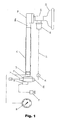
- a demand oxygen regulator 10 is powered by a pressurized O 2 source 11 through an inlet port 12.
- An adjustable back pressure regulator 14 receives pressurized O 2 on conduit or line 15 through a flow restrictor 16.
- a pressure gauge 18 provides a measure of the pressure within the outlet 22 of a demand oxygen regulator 10.
- O 2 is supplied from the demand oxygen regulator outlet 22, to a mask 20, via an inlet 58a of a balanced inhalation/exhalation patient valve 58 attached to or incorporated into the mask, and a conventional hose or tube 25.
- the inlet 58a is hereinafter sometimes referred to as the breathing appliance inlet.
- Low flow O 2 is also supplied to a nebulizer 26 from a nebulizer outlet 28, a nebulizer shut off valve 30 (incorporated in the pressure regulator as will be described in more detail) and line 27.
- the output of the nebulizer is combined with the O 2 delivered to the patient's mask through the tube 25, 29 in a conventional manner.
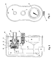
- the demand oxygen regulator 10, back pressure regulator 14 and pressure gauge 18 are mounted within a housing 32.
- the pressure gauge 18 is placed in fluid communication with the outlet 22 via line 31.
- Line 33 connects the outlet of a nebulizer valve (to be described) to the outlet 28.
- Line 34 connects a supply inlet 36 of the demand regulator 10 to the O 2 inlet nipple 12.
- the demand O 2 regulator 10 includes a demand valve 40, a maximum pressure relief valve 38 and an anti-suffocation valve 39.
- the valves 38 and 39 are mounted in a housing 42 which is secured to the demand valve housing by bolts, for example.
- the upstream interior section of the housing 41, 42 forms the outlet port 46 for the demand valve, as will be discussed in more detail in connection with Figs. 7 and 8 .
- the relief and anti-suffocation valves are conventional poppet valves with the valves 38 and 39 opening when the pressure in demand valve outlet 46 reaches a preset maximum value or falls below atmospheric pressure, respectively.
- the demand valve 40 includes the supply inlet 36, the outlet port 46, a reference pressure inlet 48 and a nebulizer valve outlet 50. The internal components of the demand valve 40 will be described in conjunction with Figs. 7 and 8 .
- the back pressure regulator valve 14 is a conventional poppet valve with a top housing section 14a, a lower housing section 14b, an inlet 14c connected to the pressurized source via restrictor 16 ( Fig. 3 ), an atmospheric outlet port 14d, and a valve plate 14e which is biased against seat 14f by spring 14g.
- An axially moveable plunger 14h responds to the rotation of knob 14i to adjust the compressive force applied by the spring to the valve plate 14e which in turn restricts the flow in line 15 from the O 2 source 11 to adjust the back pressure at inlet 14c, e.g., 1 to 20 cm H 2 O to establish the desired reference pressure in line 15a, 15 to the demand valve as will be described in connection with Figs. 7 and 8 .
- the nebulizer 26, as shown in FIG. 6 includes a container 26a for liquid medication 26b. Pressurized O 2 leaving nozzle 26c educts vaporized medication into stream 26d which enters the tube 29 adjacent the face mask during the inhalation phase of the patient's breathing cycle.
- the demand valve 40 includes a main or first diaphragm valve 52 in which first and second chambers 52a and 52b are disposed on opposite sides of a moveable diaphragm 52c.
- the diaphragm 52c closes against a seat 52d disconnecting pressurized passage 36a and the inlet 30 from passage 46a when the pressures in chambers 52a and 52b are equal due to the greater exposed surface area on the top versus the bottom side of the diaphragm.
- a second diaphragm valve 54 which controls the operation of the main valve, has a pressure reference chamber 54a (open to the reference pressure inlet 48) and a second chamber 54b disposed on opposite sides of a sensing diaphragm 54c.
- the second valve also includes a normally closed spring biased paddle assembly comprising a pivotal arm 54d biased by spring 54e to normally close pilot valve orifice 54f.
- the nebulizer (third) valve 30 includes chambers 30a and 30b, disposed on opposite sides of diaphragm 30c.
- the diaphragm 30c serves to close the nebulizer valve outlet 50 when the pressure in chambers 30a and 30b are equal due to the area of the diaphragm exposed to chamber 30b being greater than the area exposed to chamber 30a.
- a passageway 36b connects the chamber 30a to the inlet 36 as illustrated.
- a passageway 36c connects the upper chamber 52a, the pilot valve orifice 54f and inner chamber 30a to the pressurized source via a flow restrictor 36d.
- Passageway 36e connects the lower chamber 54b of valve 54 to an outlet chamber 46c of the demand valve, which chamber extends above the outlet port and circumferentially around a nozzle 46b.
- the pressure regulator 14 having been preset to the desired positive mask pressure, provides that reference pressure e.g., 1 to 20 cm H 2 O via line 15a to the reference chamber 54a.
- the main valve 52 is closed disconnecting the passage 46a and nozzle 46b from the inlet.
- demand valve outlet port 46 and outlet chamber 46c falls slightly below the reference pressure in chamber 54a, and as a result, the diaphragm 54c moves downwardly to engage the paddle valve assembly arm 54d, and lift it off of the pilot valve seat 54f. This bleeds the high pressure O 2 in line 36c to the lower pressure chamber 54b and the outlet port.
- the flow restrictor 36d allows the pressure in chamber 52a to drop below the pressure in inlet passage 36a a sufficient amount to cause the main valve 52 to open as is illustrated in FIG. 8 , to initiate the inhalation mode.
- the main valve will remain open as long as the pressure in the mask inlet and outlet chamber 46c remains below the reference pressure.
- the pressure in the outlet port 46 and chamber 54b will rise to the reference pressure thereby releasing the diaphragm 54c from the paddle wheel arm 54d and allowing the spring to close the pilot valve 54f. This action immediately allows the pressure in the line 36c and chambers 52a to rise to a level sufficient to close the main valve as is shown in Fig. 7 .
- the demand valve outlet chamber 46c and nozzle 46b compensate for this loss as is illustrated in Fig. 9 .
- the pressure in outlet chamber 46c is decreased by flow through the nozzle 46b, i.e., aspiration effect, in proportion to the flow rate.
- the nozzle and outlet chamber are designed, as illustrated in Fig. 9 , to cause an increase in the pressure in the demand valve outlet port 46 (and decrease the pressure in the chamber 46c) which pressure increase mirrors the pressure drop across the tubing and mask valve as a function of flow rate. In this manner the resulting mask pressure is maintained almost equal to the adjusted reference pressure regardless of flow rate.
- pressure representative of the breathing appliance inlet pressure includes the pressure in the mask inlet and may include the demand valve outlet port pressure where the pressure loss in the tubing and/or patient valve is not compensated for.
- the operation of the nebulizer valve 30 may best be understood by reference to Fig. 10-12 .
- the inlet pressure, e.g., 50 psi, is applied to both chambers 30a and 30b of the third valve 30 in the static condition, i.e., pilot valve 54f and main valve 52 are closed.
- the diaphragm 30c closes the nebulizer outlet 50 due to the unequal areas of the diaphragm exposed to the opposing chambers.
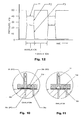
- Fig. 12 is a pressure diagram showing the pressure at various points associated with the nebulizer during inhalation and exhalation.
- Curves P1, P2 and P3 represent the pressure in line 36b, chambers 30b and outlet 50, respectively during the inhalation and exhalation modes as indicated.
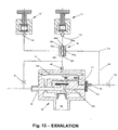
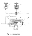
- a bi-level pressure regulator is illustrated in Fig. 13 and 14 configured in the exhalation and inhalation modes, respectively.
- An additional adjustable back pressure regulator 14' and an inhalation/exhalation responsive or selector valve 56 enables an operator to adjust separate reference pressures for the exhalation and inhalation phases of the breathing cycle.
- the valve 56 includes chambers 56a and 56b disposed on opposite sides of a diaphragm 56c.
- the valve has outlet ports 56d and 56e connected to the inlets 14c and 14c' of the pressure regulators 14 and 14' as shown.
- a first inlet port 56f is connected to line 15 and the reference chamber 54a.
- a second inlet 56g is connected to nebulizer outlet, via line 58.
- the pressure P3 ( Fig. 12 ) in line 60 and chamber 56a is low and the valve 56 is open connecting the line 15 and reference chamber to the inlets of both pressure regulators.
- the reference pressure is dictated by the pressure regulator having the lowest pressure setting, i.e., valve 14'.
- the pressure P3 in line 60 rises to force diaphragm 56c against the seat surrounding the outlet 56e thereby connecting only the inlet of the regulator 14 to the line 15 and the reference chamber.
- the reference pressure is set by the regulator 14.
- the exhalation pressure experienced by the patient may be adjusted to any level equal to or below (down to atmospheric pressure) the inhalation pressure.
- a patient's effort required to exhale may be considerably reduced.
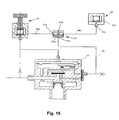
- FIG. 15 and 16 An alternative embodiment of a bi-level system is illustrated in Fig. 15 and 16 .
- This system functions in similar manner with one of the pressure regulators, i.e., regulator 55 being preadjusted at the factory to connect its input 55a to atmosphere via output 55b at a selected pressure, e.g., 10 cm H 2 O.
- a selector diaphragm valve 57 connects the outlet 14d of pressure regulator 14 to atmosphere via line 59a, inlet port 57a, and outlet port 57b during the exhalation mode as is illustrated in Fig. 15 .
- the rise in pressure in line 60 P3, Fig.
- the inhalation pressure will always be a fixed pressure (e.g., 10 cm H 2 O) above the exhalation pressure as set by the manually adjustable pressure regulator 14.
- manually adjustable as used herein is not to be interpreted as limited to a rotatable knob arrangement.
- the term is to be interpreted to include any arrangement which allows the operator to readily change the reference pressure before and during a treatment.
- Figs. 17 and 18 illustrate a cross-sectional schematic view of an improved patient valve arrangement 58 for use with or incorporation into a patient's face mask in accordance with this invention.
- the patient valve 58 comprises an inlet passage 58a terminating in an inhalation check valve 58b that acts to permit flow from the inlet 58a to an inlet/outlet chamber 58c which in turn is adapted to be placed in fluid communication with the patient's airway via a face mask etc.
- a passage 58d conducts gas (O 2 ) from the inlet to a diaphragm chamber 58e.
- This chamber is formed by the upper surface of diaphragm 58f secured at its periphery to the inner wall of valve housing 58j, the upper top central surface 58g of a circular valve member 58h and the interior of an upper section 58i of the generally cylindrically shaped valve housing 58j as illustrated.
- the valve member 58h is secured to and suspended by the radially inner portion of the diaphragm.
- This chamber 58e acts to provide pneumatic damping and pressure balance to the operation of valve member 58h. When the patient exhales, the pressure in the inlet/outlet chamber 58c rises above the pressure in the inlet 58a.
- An important design feature of the valve is the balancing of the effective areas of the diaphragm 58f (and upper surface 58g of the valve member) and the valve seat area 58m.
- the effective area of the diaphragm has a diameter d1 and the median diameter of the valve seat is d2. These two diameters are preferably about equal. This feature allows the exhalation pressure to be maintained at a level almost equal to the inhalation pressure in inlet 58a, regardless of the positive pressure level.
Description
- The present invention relates to an apparatus for use in respiratory therapy and more particularly to a portable system for use in supplying a continuous and/or dual level positive airway pressure treatment to a patient in respiratory distress and method. As used herein the term oxygen or O2 includes air and oxygen enriched air as well as purified O2.
- Individual's suffering from pulmonary edema, i.e., the effusion of serous fluid into the lungs, and certain other respiratory ailments are generally treated by forcing breathable gas, normally oxygen (O2) into the lungs and maintaining the pressure within the lungs at a level, e.g., 1 to 20 centimetres of water above atmospheric. The O2 can be supplied directly to the lungs through an endotracheal tube, one end of which is inserted into the lungs through the individual's mouth, i.e., intubation. The invasive technique of intubation requires considerable skill and can cause serious injury to the patient. Also, the recovery time of intubated patients may be considerable.
- Alternatively, a patient may be fitted with a breathing appliance such as a face mask which is equipped with an inlet for receiving oxygen under pressure and an inhalation/exhalation valve for exhausting exhaled air to the atmosphere. The respiratory departments of many hospitals have relatively sophisticated equipment for supplying oxygen at continuous and/or dual level pressure to such appliances. However, such equipment is neither readily portable nor simple to operate and often is not available in emergency rooms.
- Portable systems are currently available for use in emergency rooms by nurses and in the field by emergency rescue personnel, e.g., paramedics, for the continuous positive airway pressure ("CPAP") procedure. However, such portable systems conventionally rely on a spring loaded check valve located in or near the face mask to set the maximum pressure in the mask. The check valve serves to bypass the oxygen stream to the atmosphere during the patient's exhalation phase. The flow rate is normally adjusted to accommodate a patient's peak inhalation flow rate, e.g., 75 to 100 liters per minute (l/m). A patient typically inhales around 10 to 12 1/m with each exhalation phase exceeding the time duration of the inhalation phase by a factor of two or more.
- As a result, currently available portable systems for use by emergency rescue personnel consume oxygen at a high rate stemming from the fact that they are continuous flow devices that must cater to high demand and waste O2 during the longer expiration phase of the respiratory cycle. Also, this high flow rate creates unwanted additional expiratory work for the patient.
- In a normal respiratory cycle the torso muscles act to expand the lungs and thus draw air into them during the inhalation cycle. Exhalation is accomplished by the muscles relaxing and the elastic recoil of the chest forcing air from the lungs. During positive pressure breathing the muscle action is reversed so that air enters the lungs under pressure and exhalation requires forceful action by the abdominal muscles. Thus, exhalation under conventional CPAP treatment involves a significant amount of exertion for the patient.
- The shock to a patient being suddenly confronted with a significant amount of pressure in his or her airway, e.g., 10 to 20 cm H2O during inhalation/exhalation is another disadvantage of the currently available portable CPAP systems.
-
U.S. Patent No. 5,148,802 and related Patent Nos.5,433,193 and5,632,269 , while not directed to portable CPAP systems for use by emergency rescue personnel, disclose a sophisticated system ("'802 system") employing the CPAP treatment for individuals suffering from sleep apnea. The '802 system, which is designed to keep the individual's airway continuously open during sleep, employs a sensitive flow sensor and complicated electronic circuitry to determine when the user is exhaling and lowers the applied pressure during the expiratory phase. - The '802 system is expensive and, as with many complicated electronic devices, would be subject to failure if mishandled.
-
U.S. 4,838,257 discloses a CPAP system having a demand regulator powered by a pressurised source of gas and at least one adjustable back pressure regulator for setting the pressure in the reference chamber of the system at a selected level above atmospheric pressure. The control of the system is by a pilot valve via the flow restrictor and actuator. It is an electromagnetic control and the apparatus requires electrical power. - There is a need for a simple, inexpensive, reliable, portable and rugged apparatus which can be used by emergency rescue personnel whether in the field or in emergency rooms to ventilate a patient's lungs with oxygen under continuous positive airway pressure.
- A continuous positive airway pressure apparatus for supplying breathable gas (O2) from a pressurized source to an individual's breathing appliance in accordance with the present invention includes a demand pressure regulator for supplying O2 to the patient's breathing appliance, e.g., a face mask, only when demanded. The system includes a demand regulator with a supply inlet port adapted to be connected to the pressurized source, an outlet port adapted to be connected to the appliance's inlet, a reference chamber and a valve assembly responsive to the reference chamber/appliance inlet pressure differential for connecting and disconnecting the inlet port to and from the outlet port. The demand regulator is powered by the pressurized source.
- The apparatus further includes at least one adjustable back pressure regulator connected to the pressurized source and the reference chamber for setting the pressure in the reference chamber (and inlet to the breathing appliance) at a selected level above atmospheric pressure.
- The valve assembly comprises a first or main valve connected between the inlet and outlet ports and a main valve controller responsive to the difference in the pressure in the reference chamber and the representative appliance inlet pressure for causing the main valve to open and connect the inlet port to the outlet port when the representative appliance inlet pressure falls below the pressure in the reference chamber and for causing the main valve to close to disconnect the inlet from the outlet port when the representative of the breathing appliance inlet pressure rises to the pressure in the reference chamber. The main valve comprises a diaphragm valve with first and second actuating chambers disposed on opposite sides of the diaphragm, the area of the diaphragm exposed to the second chamber being smaller than the area of the diaphragm exposed to the first chamber. The main valve will remain closed when the pressure in the two actuating chambers is substantially the same and will open when the pressure in the first chamber falls below the pressure in the second chamber by a preset amount. The main valve controller comprises a second valve, the second valve being a diaphragm valve adapted to open when the pressure in the reference chamber is greater than the representative appliance inlet pressure.
- Further aspects of the invention are set out in the accompanying claims.
- Optionally the system may include an additional manually adjustable or fixed back pressure regulator with one regulator controlling the back pressure during inhalation and the other controlling the back pressure during exhalation and connected to the reference chamber to act in parallel or series to create bi-level pressures. The system may also include a nebulizer outlet for supplying low flow O2 to a nebulizer during the patient's inhalation phase. In addition, a preferred patient valve to be attached to or incorporated in the breathing appliance may be used with the adjustable back pressure regulator/demand valve. The improved patient valve maintains the pressure in the patient's airway very close to the selected back pressure during inhalation and exhalation regardless of the magnitude of the selected pressure level. The improved patient valve is particularly advantageous where the reference back pressure remains the same during the entire breathing cycle.
- A method of treating a patient suffering from pulmonary edema or other respiratory ailment using the apparatus of present invention includes the following steps:
- a) securing a breathing appliance to the patient's airway with the appliance having an inlet and an inhalation/exhalation valve to allow breathable gas passing through the inlet to enter the patient's lungs during the inhalation phase and allow expired air to exit to atmosphere during the exhalation phase and connecting the appliance to the CPAP apparatus of the invention;
- b) providing a pressurized source of O2;
- c)providing at least one reference pressure at a selected value above atmospheric pressure;
- d) monitoring the pressure at the appliance inlet;
- e) comparing the appliance inlet pressure with the reference pressure;
- f) connecting and disconnecting the pressurized source to the mask inlet when the inlet pressure falls below and rises to the reference pressure, respectively; and
- g) varying the selected value of the reference pressure during the treatment.
- The construction and operation of the present invention may best be understood by reference to the following description taken in conjunction with the appended drawings, wherein like components are designated with the same reference numeral in the several figures.
-
-
Fig. 1 is a system schematic of the present invention in an assembled state with a face mask and nebulizer; -
Fig. 2 is a front view of a housing in which the various components of the invention are mounted; -
Fig. 3 is a cross-sectional view of the components demand valve within the housing including a pressure regulator, pressure gauge, a maximum pressure relief valve and an anti-suffocation relief valve; -
Fig. 4 is a cross-sectional view of the demand valve and the two relief valves; -
Fig. 5 is a cross-sectional view of the pressure regulator; -
Fig. 6 is a schematic cross-sectional view of a nebulizer which may be used with the invention; -
Fig. 7 is a cross-sectional schematic view of the demand valve and pressure regulator showing the demand valve as configured during a patient's exhalation phase; -
Fig. 8 is a cross-sectional schematic view of the demand valve and pressure regulator as configured during the inhalation phase; -
Fig. 9 is a pressure diagram illustrating how the pressure at various points in the system changes with the flow rate; -
Figs. 10 and 11 are cross-sectional schematic views of the nebulizer valve configured in the exhalation and inhalation modes, respectively -
Fig. 12 is a pressure diagram showing pressures at several points in the system relevant to the operation of the nebulizer valve; -
Figs. 13 and14 are schematic cross-sectional views of a bi-level controlled demand valve functioning with two independently adjustable pressure regulators in the exhalation and inhalation modes, respectively; -
Figs. 15 and16 are schematic cross-sectional views of a bi-level controlled demand valve with only one field adjustable pressure regulator configured in the exhalation and inhalation modes, respectively; -
Figs. 17 and 18 are schematic cross-sectional views of an improved face mask valve for use with the invention as configured in the exhalation and inhalation modes, respectively; and -
Fig. 19 is a top plan view of the face mask valve showing the angle through which the atmospheric outlet stub can swivel around the housing. - Referring now to the drawings, and particularly to the system schematic of the invention shown in
Fig. 1 , ademand oxygen regulator 10 is powered by a pressurized O2 source 11 through aninlet port 12. An adjustableback pressure regulator 14 receives pressurized O2 on conduit orline 15 through aflow restrictor 16. Apressure gauge 18 provides a measure of the pressure within theoutlet 22 of ademand oxygen regulator 10. O2, at the desired pressure, is supplied from the demandoxygen regulator outlet 22, to amask 20, via aninlet 58a of a balanced inhalation/exhalation patient valve 58 attached to or incorporated into the mask, and a conventional hose ortube 25. Theinlet 58a is hereinafter sometimes referred to as the breathing appliance inlet. - Low flow O2 is also supplied to a
nebulizer 26 from anebulizer outlet 28, a nebulizer shut off valve 30 (incorporated in the pressure regulator as will be described in more detail) andline 27. The output of the nebulizer is combined with the O2 delivered to the patient's mask through thetube - Referring now to
Figs. 2 and 3 thedemand oxygen regulator 10, backpressure regulator 14 andpressure gauge 18 are mounted within ahousing 32. Thepressure gauge 18 is placed in fluid communication with theoutlet 22 vialine 31. Line 33 connects the outlet of a nebulizer valve (to be described) to theoutlet 28.Line 34 connects asupply inlet 36 of thedemand regulator 10 to the O2 inlet nipple 12. - Referring now to
Fig. 4 the demand O2 regulator 10 includes ademand valve 40, a maximumpressure relief valve 38 and ananti-suffocation valve 39. Thevalves housing 42 which is secured to the demand valve housing by bolts, for example. The upstream interior section of thehousing 41, 42 forms theoutlet port 46 for the demand valve, as will be discussed in more detail in connection withFigs. 7 and8 . - The relief and anti-suffocation valves are conventional poppet valves with the
valves demand valve outlet 46 reaches a preset maximum value or falls below atmospheric pressure, respectively. Thedemand valve 40 includes thesupply inlet 36, theoutlet port 46, areference pressure inlet 48 and anebulizer valve outlet 50. The internal components of thedemand valve 40 will be described in conjunction withFigs. 7 and8 . - Referring now to
Fig. 5 the backpressure regulator valve 14 is a conventional poppet valve with atop housing section 14a, alower housing section 14b, aninlet 14c connected to the pressurized source via restrictor 16 (Fig. 3 ), anatmospheric outlet port 14d, and avalve plate 14e which is biased againstseat 14f byspring 14g. An axiallymoveable plunger 14h responds to the rotation ofknob 14i to adjust the compressive force applied by the spring to thevalve plate 14e which in turn restricts the flow inline 15 from the O2 source 11 to adjust the back pressure atinlet 14c, e.g., 1 to 20 cm H2O to establish the desired reference pressure inline 15a, 15 to the demand valve as will be described in connection withFigs. 7 and8 . - The
nebulizer 26, as shown inFIG. 6 , includes a container 26a forliquid medication 26b. Pressurized O2 leaving nozzle 26c educts vaporized medication intostream 26d which enters thetube 29 adjacent the face mask during the inhalation phase of the patient's breathing cycle. - Referring now to
Figs. 7 and8 thedemand valve 40 includes a main orfirst diaphragm valve 52 in which first andsecond chambers 52a and 52b are disposed on opposite sides of amoveable diaphragm 52c. Thediaphragm 52c closes against aseat 52d disconnectingpressurized passage 36a and theinlet 30 from passage 46a when the pressures inchambers 52a and 52b are equal due to the greater exposed surface area on the top versus the bottom side of the diaphragm. Asecond diaphragm valve 54, which controls the operation of the main valve, has a pressure reference chamber 54a (open to the reference pressure inlet 48) and asecond chamber 54b disposed on opposite sides of asensing diaphragm 54c. The second valve also includes a normally closed spring biased paddle assembly comprising apivotal arm 54d biased byspring 54e to normally close pilot valve orifice 54f. - The nebulizer (third)
valve 30 includeschambers diaphragm 30c. Thediaphragm 30c serves to close thenebulizer valve outlet 50 when the pressure inchambers chamber 30b being greater than the area exposed tochamber 30a. Apassageway 36b connects thechamber 30a to theinlet 36 as illustrated. - A
passageway 36c connects the upper chamber 52a, the pilot valve orifice 54f andinner chamber 30a to the pressurized source via aflow restrictor 36d.Passageway 36e connects thelower chamber 54b ofvalve 54 to anoutlet chamber 46c of the demand valve, which chamber extends above the outlet port and circumferentially around anozzle 46b. - In the operation of the system of
Fig. 7 and8 thepressure regulator 14, having been preset to the desired positive mask pressure, provides that reference pressure e.g., 1 to 20 cm H2O via line 15a to the reference chamber 54a. In the exhalation mode themain valve 52 is closed disconnecting the passage 46a andnozzle 46b from the inlet. When the patient begins to inhale the low pressure in the mask inlet, demandvalve outlet port 46 andoutlet chamber 46c falls slightly below the reference pressure in chamber 54a, and as a result, thediaphragm 54c moves downwardly to engage the paddlevalve assembly arm 54d, and lift it off of the pilot valve seat 54f. This bleeds the high pressure O2 inline 36c to thelower pressure chamber 54b and the outlet port. - The
flow restrictor 36d allows the pressure in chamber 52a to drop below the pressure ininlet passage 36a a sufficient amount to cause themain valve 52 to open as is illustrated inFIG. 8 , to initiate the inhalation mode. The main valve will remain open as long as the pressure in the mask inlet andoutlet chamber 46c remains below the reference pressure. When the patient initiates his or her exhalation phase the pressure in theoutlet port 46 andchamber 54b will rise to the reference pressure thereby releasing thediaphragm 54c from thepaddle wheel arm 54d and allowing the spring to close the pilot valve 54f. This action immediately allows the pressure in theline 36c and chambers 52a to rise to a level sufficient to close the main valve as is shown inFig. 7 . - In this manner O2 is supplied to the patient only on demand and at a pressure level which can be determined by the operator prior to and/or during the treatment. This results in a considerable saving of O2 over the O2 consumed by the conventional portable CPAP systems.
- There is a pressure drop across the hose or tubing which connects the mask inlet to the demand valve outlet port as well as in the mask valve itself, which pressure drop is proportional to the O2 flow rate. The demand
valve outlet chamber 46c andnozzle 46b compensate for this loss as is illustrated inFig. 9 . The pressure inoutlet chamber 46c is decreased by flow through thenozzle 46b, i.e., aspiration effect, in proportion to the flow rate. The nozzle and outlet chamber are designed, as illustrated inFig. 9 , to cause an increase in the pressure in the demand valve outlet port 46 (and decrease the pressure in thechamber 46c) which pressure increase mirrors the pressure drop across the tubing and mask valve as a function of flow rate. In this manner the resulting mask pressure is maintained almost equal to the adjusted reference pressure regardless of flow rate. - It is to be noted that the term pressure representative of the breathing appliance inlet pressure includes the pressure in the mask inlet and may include the demand valve outlet port pressure where the pressure loss in the tubing and/or patient valve is not compensated for.
- The operation of the
nebulizer valve 30 may best be understood by reference toFig. 10-12 . The inlet pressure, e.g., 50 psi, is applied to bothchambers third valve 30 in the static condition, i.e., pilot valve 54f andmain valve 52 are closed. In the absence of O2 flow through themain valve 52, e.g., exhalation mode, thediaphragm 30c closes thenebulizer outlet 50 due to the unequal areas of the diaphragm exposed to the opposing chambers. When the pilot and main valves open, at the initiation of inhalation, the pressure (P1) inpassageway 36c decreases immediately, as explained earlier, allowing thediaphragm 30c to open the nebulizer valve. This allows O2 to flow through restrictor 30d (Fig. 10 ), into thenebulizer outlet 50, throughrestrictor 54 to thenebulizer nozzle 26c. -
Fig. 12 is a pressure diagram showing the pressure at various points associated with the nebulizer during inhalation and exhalation. Curves P1, P2 and P3 represent the pressure inline 36b,chambers 30b andoutlet 50, respectively during the inhalation and exhalation modes as indicated. - A bi-level pressure regulator is illustrated in
Fig. 13 and14 configured in the exhalation and inhalation modes, respectively. An additional adjustable back pressure regulator 14' and an inhalation/exhalation responsive orselector valve 56 enables an operator to adjust separate reference pressures for the exhalation and inhalation phases of the breathing cycle. Thevalve 56 includeschambers 56a and 56b disposed on opposite sides of adiaphragm 56c. The valve hasoutlet ports inlets pressure regulators 14 and 14' as shown. A first inlet port 56f is connected to line 15 and the reference chamber 54a. A second inlet 56g is connected to nebulizer outlet, vialine 58. - In the exhalation mode the pressure P3 (
Fig. 12 ) inline 60 and chamber 56a is low and thevalve 56 is open connecting theline 15 and reference chamber to the inlets of both pressure regulators. As a result the reference pressure is dictated by the pressure regulator having the lowest pressure setting, i.e., valve 14'. In the inhalation mode, with the main valve open, the pressure P3 inline 60 rises to forcediaphragm 56c against the seat surrounding theoutlet 56e thereby connecting only the inlet of theregulator 14 to theline 15 and the reference chamber. In this mode the reference pressure is set by theregulator 14. - Where the system is equipped with two independently adjustable pressure regulators, as in
Fig. 13 and14 , the exhalation pressure experienced by the patient may be adjusted to any level equal to or below (down to atmospheric pressure) the inhalation pressure. Thus, a patient's effort required to exhale may be considerably reduced. - An alternative embodiment of a bi-level system is illustrated in
Fig. 15 and16 . This system functions in similar manner with one of the pressure regulators, i.e.,regulator 55 being preadjusted at the factory to connect itsinput 55a to atmosphere via output 55b at a selected pressure, e.g., 10 cm H2O. Aselector diaphragm valve 57 connects theoutlet 14d ofpressure regulator 14 to atmosphere via line 59a,inlet port 57a, andoutlet port 57b during the exhalation mode as is illustrated inFig. 15 . During the inhalation mode (Fig. 16 ) the rise in pressure in line 60 (P3,Fig. 12 ) transmitted throughinlet orifice 57c causesdiaphragm 57d to closeoutlet 57b, connecting the outlet ofpressure regulator 14 to theinlet 55a ofpressure regulator 55. Thus, the inhalation pressure will always be a fixed pressure (e.g., 10 cm H2O) above the exhalation pressure as set by the manuallyadjustable pressure regulator 14. - It is to be noted that the term manually adjustable as used herein is not to be interpreted as limited to a rotatable knob arrangement. The term is to be interpreted to include any arrangement which allows the operator to readily change the reference pressure before and during a treatment.
-
Figs. 17 and 18 illustrate a cross-sectional schematic view of an improvedpatient valve arrangement 58 for use with or incorporation into a patient's face mask in accordance with this invention. Thepatient valve 58 comprises aninlet passage 58a terminating in an inhalation check valve 58b that acts to permit flow from theinlet 58a to an inlet/outlet chamber 58c which in turn is adapted to be placed in fluid communication with the patient's airway via a face mask etc. Apassage 58d conducts gas (O2) from the inlet to adiaphragm chamber 58e. This chamber is formed by the upper surface of diaphragm 58f secured at its periphery to the inner wall ofvalve housing 58j, the upper topcentral surface 58g of acircular valve member 58h and the interior of anupper section 58i of the generally cylindrically shapedvalve housing 58j as illustrated. Thevalve member 58h is secured to and suspended by the radially inner portion of the diaphragm. Thischamber 58e acts to provide pneumatic damping and pressure balance to the operation ofvalve member 58h. When the patient exhales, the pressure in the inlet/outlet chamber 58c rises above the pressure in theinlet 58a. This causes check valve 58b to close, allowing diaphragm 58f andvalve member 58h to move upwardly lifting the valve member off of itsannular seat 58m formed at the upper (terminal) end of the inlet/outlet chamber 56c. Flow is then directed through anexhaust casing 58k which surrounds the valve seat and thence to exhaustport 58n and to atmosphere via passage 58o. The exhaust port, formed inexhaust casing 58k, which is rotatable through an angle of about 300°. with respect to thevalve housing 58j allows the patient's expired air to be directed as desired. - An important design feature of the valve is the balancing of the effective areas of the diaphragm 58f (and
upper surface 58g of the valve member) and thevalve seat area 58m. The effective area of the diaphragm has a diameter d1 and the median diameter of the valve seat is d2. These two diameters are preferably about equal. This feature allows the exhalation pressure to be maintained at a level almost equal to the inhalation pressure ininlet 58a, regardless of the positive pressure level. - There has thus been described a novel apparatus or system for supplying breathable gas such as O2 under the continuous positive airway pressure technique which is portable, rugged, simple to use and very conservative in its use of O2. Various modifications and additions to the disclosed apparatus will occur to those skilled in the art without involving any departing from the scope of the invention as defined in the appended claims.
Claims (21)
- A continuous positive airway pressure apparatus for supplying breathable gas from a pressurized source (11) to an individual's breathing appliance, which appliance has an inlet for receiving the gas and an inhalation/exhalation valve for routing the gas to the individual's lungs and the exhaled air to the atmosphere, the continuous positive airway pressure apparatus comprising:a demand regulator (10) having a supply inlet port (12) adapted to be connected to the pressurized source (11), an outlet port (22) adapted to be connected to the appliance's inlet, a reference chamber (54a) and a valve assembly (40) responsive to the reference chamber pressure and a pressure representative of the appliance inlet pressure for connecting and disconnecting the inlet port (12) to and from the outlet port (22), wherein the demand regulator (10) is powered by the pressurized source; andat least one adjustable back pressure regulator (14) connected to the pressurized source and the reference chamber (54a) for setting the pressure in the reference chamber (54a) at a selected level above atmospheric pressure,characterised in that:the valve assembly (40) comprises a first or main valve (52) connected between the inlet (12) and outlet (22) ports and a second or control valve (54) responsive to the difference in the pressure in the reference chamber (54a) and the representative appliance inlet pressure for causing the main valve (52) to open and connect the inlet port (12) to the outlet port (22) when the representative appliance inlet pressure falls below the pressure in the reference chamber (54a) and for causing the main valve (52) to close to disconnect the inlet (12) from the outlet (22) port when the representative of the breathing appliance inlet pressure rises to the pressure in the reference chamber (54a),the main valve (52) comprises a diaphragm valve with first (52a) and second (52b) actuating chambers disposed on opposite sides of the diaphragm (52c), the area of the diaphragm (52c) exposed to the second chamber (52b) being smaller than the area of the diaphragm exposed to the first chamber (52a) whereby the main valve (52) will remain closed when the pressure in the two actuating chambers is substantially the same and will open when the pressure in the first chamber (52a) falls below the pressure in the second chamber (52b) by a preset amount, andthe second valve (54) comprises a diaphragm valve adapted to open when the pressure in the reference chamber (54a) is greater than the representative appliance inlet pressure.
- The invention of claim 1, wherein the valve assembly (40) includes an outlet chamber (46c) upstream from the outlet port (22), the pressure in the outlet chamber being representative of the pressure in the breathing appliance inlet.
- The invention of either claim 1 or claim 2, wherein the valve assembly (40) includes a pressurized nebulizer outlet (50) and a third valve (30) responsive to the status of the second valve (54) for connecting and disconnecting the nebulizer outlet (50) to the inlet port (12) when the second valve (54) is closed and opened, respectively.
- The invention of claim 3, wherein the third valve (30) is a diaphragm valve and includes a first chamber (30a) and a second chamber (30b) disposed on opposite sides of the diaphragm (30c), the first chamber (30a) being in fluid communication with the first chamber (57a) of the main valve (52), the second chamber (30b) of the third valve (30) being in fluid communication with the nebulizer outlet (50) and with the second chamber (52b) of the main valve (52) through a flow restrictor.
- The invention of any of claims 1-3, wherein the second valve (54) includes a pressure reference chamber (54a) and a second chamber (54b) disposed on opposite sides of a pressure sensing diaphragm (54c), the second chamber being in fluid communication with the outlet port (22).
- The invention of claim 5, wherein the first (52a) and second (52b) chambers of the main valve (52) are connected to the inlet port (12), wherein the connection to the first chamber (52a) includes a restrictor (32d) for restricting the flow rate.
- The invention of claim 6, wherein the second valve (54) further includes a normally closed pilot valve orifice (54f) connected to the first chamber (52a) of the main valve (52), wherein the pilot valve orifice (54f) is configured to selectively allow communication between the first chamber (52a) of the main valve (52) to the second chamber (54b) of the second valve (54) in response to the movement of the pressure sensing diaphragm (54c) as a result of the pressure in the second chamber (54b) of the second valve (54) falling below the pressure in the reference chamber (54a).
- The invention of claim 7, wherein the second valve (54) further includes a pivotal arm (54d) that is biased by a spring (54e), which are configured to normally close pilot valve orifce (54f).
- The invention of any of claims 1-8, wherein said at least one adjustable pressure regulator (14) includes a line (15) with a flow restrictor connected between the pressurized source (11) and the pressure reference chamber (54a) and a first adjustable poppet valve connected between said line upstream from the flow restrictor and atmosphere.
- The invention of any of claims 1-9, wherein said at least one pressure regulator (14) comprises two pressure regulators (14 and 14'), at least one which is manually adjustable and an inhalation/exhalation selector (56), the two pressure regulators in conjunction with the selector (56) being arranged to set the pressure in the pressure reference chamber (54a) at one level during the inhalation phase and at a different level during the exhalation phase.
- The invention of claim 10, wherein the pressure reference chamber (54a) is connected to the pressurized source (11) through a restrictor (16) and wherein each pressure regulator (14, 14') includes a poppet valve, each poppet valve having an inlet and an outlet, the outlets being in fluid communication with the atmosphere, the inlet of one of the poppet valves being in constant fluid communication with the pressure reference chamber (54a) upstream from the restrictor, and further including a fourth valve (57) for placing the inlet of the other poppet valve in fluid communication with the pressure reference chamber (54a), upstream of the restrictor, in response to the closure of the main valve (52).
- The invention of claim 11, wherein both pressure regulators (14, 14') are manually adjustable.
- The invention of either claim 11 or claim 12, wherein the fourth valve is a diaphragm (57d) valve.
- The invention of claim 13, wherein the fourth valve (57) includes first and second chambers disposed on opposite sides of the diaphragm with the first chamber being in fluid communication with the nebulizer outlet and the second chamber being in fluid communication with the reference chamber (54a).
- The invention of claim 10, wherein the other pressure regulator (14') is not manually adjustable by an operator in the field and functions to set the pressure in the pressure reference chamber (54a) at a set pressure above the exhalation reference pressure during the inhalation phase.
- The invention of claim 15, wherein each of the pressure regulators includes a poppet valve and the selector comprises a diaphragm valve.
- The invention of any of claims 1-16, further including a nozzle (46b) disposed upstream of the outlet port (22) and in an educting relationship with the outlet chamber so that the pressure in the outlet chamber varies with the flow rate of gas through the nozzle to compensate for pressure losses between the outlet port and the breathing appliance inlet.
- The invention of any of claims 1-18, further comprising a patient inhalation/exhalation valve (58) for directing breathable gas from a pressure regulated source (11) to a patient's lungs and exhausting the patents expired air to the atmosphere comprising:a housing (58j) having an upper section (58i) and an interior wall, the housing further having an inlet (58a) adapted to be connected to the regulated source (11), an exhaust port (58m) in fluid communication with the atmosphere and an inlet/outlet chamber (58c) adapted to be placed in fluid communication with the patient's lungs;an inhalation valve (58b) disposed between the inlet (58a) and the inlet/outlet chamber (58c);a flexible diaphragm (58f) secured at its periphery to the inner wall of the housing (58j) nd suspending a rigid valve member (58h), the diaphragm and valve member forming a first chamber (58e) with the interior of the upper housing section;the inlet/outlet chamber (58c) terminating at its upper end (58g) in a circular valve seat arranged to engage a lower circular sealing area of the rigid valve member (58h), the valve member and the seat forming an exhalation valve so that when the valve member (58h) is positioned above the seat the exhalation valve is opened connecting the inlet/outlet chamber (58c) to the exhaust port (58m) and when the valve member engages the seat the exhalation valve is closed;the first chamber (58c) being in fluid communication with the housing inlet (58a);the effective area of the diaphragm (58f) and valve member (58h) supported thereby being about equal to the area of the circular valve seat whereby the exhalation pressure is maintained at a level approximately equal to the pressure in the inlet.
- The invention of claim 18 wherein the housing defines an annular exhalation chamber surrounding the valve seat in fluid communication with the exhaust port (58m).
- The invention of claim 19 wherein the exhaust port (58m) is formed in an exhaust casing (581) rotatably mounted on the housing (58j).
- The invention of claim 20 wherein the diameter d1 of the effective area of the diaphragm (58f) and the medium diameter d2 valve member seat is substantially equal.
Applications Claiming Priority (5)
| Application Number | Priority Date | Filing Date | Title |
|---|---|---|---|
| US28871301P | 2001-05-07 | 2001-05-07 | |
| US288713P | 2001-05-07 | ||
| US20544 | 2001-11-29 | ||
| US10/020,544 US7066175B2 (en) | 2001-05-07 | 2001-11-29 | Portable gas powered positive pressure breathing apparatus and method |
| PCT/US2002/014184 WO2002089873A2 (en) | 2001-05-07 | 2002-05-06 | Pressure regulating valve and positive pressure ventilation system |
Publications (3)
| Publication Number | Publication Date |
|---|---|
| EP1385579A2 EP1385579A2 (en) | 2004-02-04 |
| EP1385579A4 EP1385579A4 (en) | 2007-03-21 |
| EP1385579B1 true EP1385579B1 (en) | 2012-09-05 |
Family
ID=26693574
Family Applications (1)
| Application Number | Title | Priority Date | Filing Date |
|---|---|---|---|
| EP02744135A Expired - Lifetime EP1385579B1 (en) | 2001-05-07 | 2002-05-06 | Portable gas powered positive pressure breathing apparatus |
Country Status (7)
| Country | Link |
|---|---|
| US (3) | US7066175B2 (en) |
| EP (1) | EP1385579B1 (en) |
| JP (1) | JP2005508203A (en) |
| AU (1) | AU2002340765B2 (en) |
| CA (1) | CA2446614C (en) |
| MX (1) | MXPA03010124A (en) |
| WO (1) | WO2002089873A2 (en) |
Families Citing this family (81)
| Publication number | Priority date | Publication date | Assignee | Title |
|---|---|---|---|---|
| US7588033B2 (en) | 2003-06-18 | 2009-09-15 | Breathe Technologies, Inc. | Methods, systems and devices for improving ventilation in a lung area |
| FR2858236B1 (en) | 2003-07-29 | 2006-04-28 | Airox | DEVICE AND METHOD FOR SUPPLYING RESPIRATORY GAS IN PRESSURE OR VOLUME |
| AU2004266693B2 (en) | 2003-08-18 | 2011-03-10 | Breathe Technologies, Inc | Method and device for non-invasive ventilation with nasal interface |
| US7100628B1 (en) * | 2003-11-18 | 2006-09-05 | Creare Inc. | Electromechanically-assisted regulator control assembly |
| US7946291B2 (en) * | 2004-04-20 | 2011-05-24 | Novartis Ag | Ventilation systems and methods employing aerosol generators |
| BRPI0509991A (en) * | 2004-04-20 | 2007-10-16 | Aerogen Inc | aerosol delivery apparatus, methods and compositions for pressure-assisted breathing systems |
| US7469698B1 (en) * | 2004-09-14 | 2008-12-30 | Winthrop De Childers | Parameter optimization in sleep apnea treatment apparatus |
| CN101454041B (en) | 2005-09-20 | 2012-12-12 | 呼吸科技公司 | Systems, methods and apparatus for respiratory support of a patient |
| US7762252B2 (en) * | 2006-04-26 | 2010-07-27 | Mine Safety Appliances Company | Devices, systems and methods for operation of breathing apparatuses in multiple modes |
| CN101541365A (en) | 2006-05-18 | 2009-09-23 | 呼吸科技公司 | Tracheostoma tracheotomy method and device |
| JP2009545384A (en) | 2006-08-03 | 2009-12-24 | ブリーズ テクノロジーズ, インコーポレイテッド | Method and apparatus for minimally invasive respiratory assistance |
| WO2008101302A1 (en) * | 2007-02-23 | 2008-08-28 | Resmed Ltd | Demand valve for breathing apparatus |
| WO2008144589A1 (en) | 2007-05-18 | 2008-11-27 | Breathe Technologies, Inc. | Methods and devices for sensing respiration and providing ventilation therapy |
| CN101888868B (en) | 2007-09-26 | 2014-01-22 | 呼吸科技公司 | Methods and devices for treating sleep apnea |
| CN101873875B (en) | 2007-09-26 | 2014-11-12 | 呼吸科技公司 | Methods and devices for providing inspiratory and expiratory flow relief during ventilation therapy |
| US8770193B2 (en) | 2008-04-18 | 2014-07-08 | Breathe Technologies, Inc. | Methods and devices for sensing respiration and controlling ventilator functions |
| US8776793B2 (en) | 2008-04-18 | 2014-07-15 | Breathe Technologies, Inc. | Methods and devices for sensing respiration and controlling ventilator functions |
| US8457706B2 (en) | 2008-05-16 | 2013-06-04 | Covidien Lp | Estimation of a physiological parameter using a neural network |
| CA2734296C (en) | 2008-08-22 | 2018-12-18 | Breathe Technologies, Inc. | Methods and devices for providing mechanical ventilation with an open airway interface |
| US8302602B2 (en) | 2008-09-30 | 2012-11-06 | Nellcor Puritan Bennett Llc | Breathing assistance system with multiple pressure sensors |
| JP5711661B2 (en) | 2008-10-01 | 2015-05-07 | ブリーズ・テクノロジーズ・インコーポレーテッド | Ventilator with biofeedback monitoring and controls to improve patient activity and health |
| US9132250B2 (en) | 2009-09-03 | 2015-09-15 | Breathe Technologies, Inc. | Methods, systems and devices for non-invasive ventilation including a non-sealing ventilation interface with an entrainment port and/or pressure feature |
| WO2010115166A1 (en) | 2009-04-02 | 2010-10-07 | Breathe Technologies, Inc. | Methods, systems and devices for non-invasive open ventilation with gas delivery nozzles in free space |
| GB2468144B (en) * | 2009-02-26 | 2013-01-23 | Grimsey Marine Technology Ltd | Double counterlung breathing apparatus |
| US8434479B2 (en) | 2009-02-27 | 2013-05-07 | Covidien Lp | Flow rate compensation for transient thermal response of hot-wire anemometers |
| US9962512B2 (en) | 2009-04-02 | 2018-05-08 | Breathe Technologies, Inc. | Methods, systems and devices for non-invasive ventilation including a non-sealing ventilation interface with a free space nozzle feature |
| WO2011029074A1 (en) | 2009-09-03 | 2011-03-10 | Breathe Technologies, Inc. | Methods, systems and devices for non-invasive ventilation including a non-sealing ventilation interface with an entrainment port and/or pressure feature |
| US20110067698A1 (en) * | 2009-09-22 | 2011-03-24 | O-Two Medical Technologies Inc. | Handheld device for delivering continuous positive airway pressure |
| US8439036B2 (en) | 2009-12-01 | 2013-05-14 | Covidien Lp | Exhalation valve assembly with integral flow sensor |
| US8469031B2 (en) | 2009-12-01 | 2013-06-25 | Covidien Lp | Exhalation valve assembly with integrated filter |
| US8469030B2 (en) | 2009-12-01 | 2013-06-25 | Covidien Lp | Exhalation valve assembly with selectable contagious/non-contagious latch |
| US8439037B2 (en) | 2009-12-01 | 2013-05-14 | Covidien Lp | Exhalation valve assembly with integrated filter and flow sensor |
| CN106955401B (en) | 2010-03-25 | 2020-11-06 | 瑞思迈巴黎股份有限公司 | Breathable gas inlet control apparatus for respiratory therapy device |
| US20110253147A1 (en) * | 2010-04-19 | 2011-10-20 | Gusky Michael H | Breathing apparatus |
| USD653749S1 (en) | 2010-04-27 | 2012-02-07 | Nellcor Puritan Bennett Llc | Exhalation module filter body |
| USD655809S1 (en) | 2010-04-27 | 2012-03-13 | Nellcor Puritan Bennett Llc | Valve body with integral flow meter for an exhalation module |
| USD655405S1 (en) | 2010-04-27 | 2012-03-06 | Nellcor Puritan Bennett Llc | Filter and valve body for an exhalation module |
| US20120012107A1 (en) * | 2010-07-19 | 2012-01-19 | Mercury Enterprises, Inc. | Apparatus for resuscitation |
| US8783255B2 (en) * | 2010-07-30 | 2014-07-22 | Covidien Lp | Medical device tube having suction lumen and an associated suctioning system |
| CN103096981B (en) | 2010-08-16 | 2015-07-22 | 呼吸科技公司 | Methods, systems and devices using lox to provide ventilatory support |
| US8939152B2 (en) | 2010-09-30 | 2015-01-27 | Breathe Technologies, Inc. | Methods, systems and devices for humidifying a respiratory tract |
| CN103189092B (en) | 2010-10-14 | 2016-08-03 | 文提菲克控股有限公司 | Breather valve device |
| CN102266608B (en) * | 2010-12-31 | 2014-02-26 | 北京谊安医疗系统股份有限公司 | Pressure detection device and breathing machine with same |
| US20120253218A1 (en) * | 2011-01-04 | 2012-10-04 | Rosenthal Richard R | Apparatus and method for eucapnic voluntary hyperventilation testing |
| US9084859B2 (en) | 2011-03-14 | 2015-07-21 | Sleepnea Llc | Energy-harvesting respiratory method and device |
| US9629971B2 (en) | 2011-04-29 | 2017-04-25 | Covidien Lp | Methods and systems for exhalation control and trajectory optimization |
| US9364624B2 (en) | 2011-12-07 | 2016-06-14 | Covidien Lp | Methods and systems for adaptive base flow |
| US9498589B2 (en) | 2011-12-31 | 2016-11-22 | Covidien Lp | Methods and systems for adaptive base flow and leak compensation |
| US8844526B2 (en) | 2012-03-30 | 2014-09-30 | Covidien Lp | Methods and systems for triggering with unknown base flow |
| EP3998097A1 (en) | 2012-04-05 | 2022-05-18 | Fisher & Paykel Healthcare Limited | Respiratory assistance apparatus |
| US9144658B2 (en) | 2012-04-30 | 2015-09-29 | Covidien Lp | Minimizing imposed expiratory resistance of mechanical ventilator by optimizing exhalation valve control |
| US9669172B2 (en) | 2012-07-05 | 2017-06-06 | Resmed Limited | Discreet respiratory therapy system |
| JP5937476B2 (en) * | 2012-09-28 | 2016-06-22 | 帝人ファーマ株式会社 | Oxygen supply equipment |
| DE102012020917A1 (en) * | 2012-10-25 | 2014-04-30 | Dräger Medical GmbH | Elbow for a respiratory mask |
| CA2832687A1 (en) * | 2012-11-26 | 2014-05-26 | Beng Leong Toh | Pulse generator systems for therapy device |
| US9795756B2 (en) | 2012-12-04 | 2017-10-24 | Mallinckrodt Hospital Products IP Limited | Cannula for minimizing dilution of dosing during nitric oxide delivery |
| ES2773718T3 (en) | 2012-12-04 | 2020-07-14 | Mallinckrodt Hospital Products Ip Ltd | Cannula to minimize dissolution of the dosage during administration of nitric oxide |
| USD731049S1 (en) | 2013-03-05 | 2015-06-02 | Covidien Lp | EVQ housing of an exhalation module |
| USD731065S1 (en) | 2013-03-08 | 2015-06-02 | Covidien Lp | EVQ pressure sensor filter of an exhalation module |
| USD744095S1 (en) | 2013-03-08 | 2015-11-24 | Covidien Lp | Exhalation module EVQ internal flow sensor |
| USD692556S1 (en) | 2013-03-08 | 2013-10-29 | Covidien Lp | Expiratory filter body of an exhalation module |
| USD736905S1 (en) | 2013-03-08 | 2015-08-18 | Covidien Lp | Exhalation module EVQ housing |
| USD701601S1 (en) | 2013-03-08 | 2014-03-25 | Covidien Lp | Condensate vial of an exhalation module |
| USD731048S1 (en) | 2013-03-08 | 2015-06-02 | Covidien Lp | EVQ diaphragm of an exhalation module |
| USD693001S1 (en) | 2013-03-08 | 2013-11-05 | Covidien Lp | Neonate expiratory filter assembly of an exhalation module |
| US9981096B2 (en) | 2013-03-13 | 2018-05-29 | Covidien Lp | Methods and systems for triggering with unknown inspiratory flow |
| US9950135B2 (en) | 2013-03-15 | 2018-04-24 | Covidien Lp | Maintaining an exhalation valve sensor assembly |
| CN106535972B (en) | 2014-05-27 | 2019-09-03 | 费雪派克医疗保健有限公司 | Gas mixing and measurement for medical device |
| US9808591B2 (en) | 2014-08-15 | 2017-11-07 | Covidien Lp | Methods and systems for breath delivery synchronization |
| US10406312B2 (en) | 2014-10-21 | 2019-09-10 | Stephen Donald Flynn | CPAP flow driver for using nebulizer with CPAP apparatus |
| US9950129B2 (en) | 2014-10-27 | 2018-04-24 | Covidien Lp | Ventilation triggering using change-point detection |
| US9925346B2 (en) | 2015-01-20 | 2018-03-27 | Covidien Lp | Systems and methods for ventilation with unknown exhalation flow |
| US10905836B2 (en) | 2015-04-02 | 2021-02-02 | Hill-Rom Services Pte. Ltd. | Manifold for respiratory device |
| USD775345S1 (en) | 2015-04-10 | 2016-12-27 | Covidien Lp | Ventilator console |
| USD776278S1 (en) * | 2015-10-30 | 2017-01-10 | Mallinckrodt Hospital Products IP Limited | MRI compatible therapeutic gas injector module |
| WO2017095241A2 (en) | 2015-12-02 | 2017-06-08 | Fisher & Paykel Healthcare Limited | Flow path sensing for flow therapy apparatus |
| US20210205567A1 (en) * | 2016-08-02 | 2021-07-08 | Adel Bougatef | Method and apparatus for providing percussive ventilation therapy to a patient airway |
| US10792449B2 (en) | 2017-10-03 | 2020-10-06 | Breathe Technologies, Inc. | Patient interface with integrated jet pump |
| US11324954B2 (en) | 2019-06-28 | 2022-05-10 | Covidien Lp | Achieving smooth breathing by modified bilateral phrenic nerve pacing |
| US11896767B2 (en) | 2020-03-20 | 2024-02-13 | Covidien Lp | Model-driven system integration in medical ventilators |
| CN114306850B (en) * | 2022-01-21 | 2023-07-18 | 重庆市人民医院 | Oxygen supplying instrument for purifying treatment |
Family Cites Families (66)
| Publication number | Priority date | Publication date | Assignee | Title |
|---|---|---|---|---|
| US2608971A (en) * | 1948-11-17 | 1952-09-02 | Bendix Aviat Corp | Demand valve control mechanism |
| US2608200A (en) * | 1951-05-17 | 1952-08-26 | Richard E Stockman | Oxygen demand regulator, including altitude compensator |
| US2988085A (en) * | 1957-06-17 | 1961-06-13 | Robertshaw Fulton Controls Co | Breathing apparatus |
| US3362404A (en) * | 1964-11-16 | 1968-01-09 | Bennett Respiration Products I | Respiration apparatus for administering intermittent positive pressure breathing therapy |
| US3693653A (en) * | 1971-01-29 | 1972-09-26 | Robert L Cramer | Fluid mixing regulator |
| US3752175A (en) * | 1971-08-20 | 1973-08-14 | Robertshaw Controls Co | Altitude compensating pressure regulator |
| US3795257A (en) * | 1972-03-27 | 1974-03-05 | Robertshaw Controls Co | Demand valve assembly for use with breathing or resuscitation equipment |
| US3834383A (en) * | 1972-12-11 | 1974-09-10 | Puritan Bennett Corp | Respiration apparatus with flow responsive control valve |
| US3859995A (en) * | 1973-07-02 | 1975-01-14 | Westinghouse Electric Corp | Breathing assist apparatus |
| DE2404062C3 (en) * | 1974-01-29 | 1978-04-20 | Draegerwerk Ag, 2400 Luebeck | Breathing gas supply regulators, in particular for high-altitude breathing apparatus |
| US4141356A (en) * | 1976-06-16 | 1979-02-27 | Bourns, Inc. | Respirator system and method |
| US4178940A (en) * | 1977-06-24 | 1979-12-18 | Au Anthony S | Pressure control systems |
| US4186737A (en) * | 1977-11-10 | 1980-02-05 | Airco, Inc. | Drug nebulizing system for medical ventilators of the volume-limited type |
| US4279250A (en) * | 1977-11-10 | 1981-07-21 | Airco, Inc. | Drug nebulizing system for medical ventilators of the volume-limited type |
| US4278110A (en) * | 1979-11-13 | 1981-07-14 | Price Ernest H | Demand responsive flow controller |
| US4667670A (en) | 1982-03-20 | 1987-05-26 | Racal Panorama Limited | Gas flow control valves |
| US4655213A (en) * | 1983-10-06 | 1987-04-07 | New York University | Method and apparatus for the treatment of obstructive sleep apnea |
| FI78514C (en) * | 1983-12-16 | 1989-08-10 | Sicpa Holding Sa | TRANSFERTRYCKPLATTA, FOERFARANDE FOER DESS FRAMSTAELLNING, TRYCKSVAERTA FOER ANVAENDNING I FOERFARANDET SAMT TRANSFERTRYCKNINGSFOERFARANDE FOER ATT TRYCKA TEXTILUNDERLAG MEDELST TRANSFERTRYCKPLATTAN. |
| FR2573311B1 (en) * | 1984-11-20 | 1988-06-24 | Boc Sa Ohmeda | ARTIFICIAL VENTILATION APPARATUS HAVING A VOLUMETRIC INSPIRATORY ASSISTANCE DEVICE |
| GB8511170D0 (en) * | 1985-05-02 | 1985-06-12 | Pneupac Ltd | Resuscitator/ventilator |
| JPS6294175A (en) * | 1985-10-18 | 1987-04-30 | 鳥取大学長 | Respiration synchronous type gas blowing apparatus and method |
| US4648397A (en) * | 1985-10-28 | 1987-03-10 | The United States Of America As Represented By The Secretary Of The Air Force | Electronically compensated pressure dilution demand regulator |
| AU593903B2 (en) * | 1986-05-07 | 1990-02-22 | Peter Joseph Jackson | Pressure regulator |
| US4773411A (en) * | 1986-05-08 | 1988-09-27 | Downs John B | Method and apparatus for ventilatory therapy |
| DE3636669C2 (en) * | 1986-10-28 | 2001-08-16 | Siemens Ag | Arrangement for delivering aerosol to a patient's airways and / or lungs |
| US4784130A (en) * | 1986-12-04 | 1988-11-15 | The John Bunn Company | Flow controller |
| US5360000A (en) * | 1987-03-19 | 1994-11-01 | Puritan-Bennett Corporation | Pneumatic demand oxygen valve |
| US4827964A (en) * | 1987-04-23 | 1989-05-09 | Mine Safety Appliances Company | System for metering of breathing gas for accommodation of breathing demand |
| US4838257A (en) * | 1987-07-17 | 1989-06-13 | Hatch Guy M | Ventilator |
| US4971050A (en) * | 1987-11-03 | 1990-11-20 | Respirator Research Ltd. | Open circuit emergency breathing apparatus and pressure demand valve therefor |
| US4898174A (en) * | 1988-05-03 | 1990-02-06 | Life Support Products, Inc. | Automatic ventilator |
| US5165397A (en) * | 1988-12-15 | 1992-11-24 | Arp Leon J | Method and apparatus for demand oxygen system monitoring and control |
| US5074298A (en) * | 1989-09-01 | 1991-12-24 | E. I. Du Pont De Nemours And Company | Gas flow control system |
| US5632269A (en) * | 1989-09-22 | 1997-05-27 | Respironics Inc. | Breathing gas delivery method and apparatus |
| USRE35295E (en) * | 1989-09-22 | 1996-07-16 | Respironics, Inc. | Sleep apnea treatment apparatus |
| US5239995A (en) * | 1989-09-22 | 1993-08-31 | Respironics, Inc. | Sleep apnea treatment apparatus |
| US5148802B1 (en) * | 1989-09-22 | 1997-08-12 | Respironics Inc | Method and apparatus for maintaining airway patency to treat sleep apnea and other disorders |
| US5000174A (en) * | 1989-10-03 | 1991-03-19 | Cairns & Brother Inc. | Positive pressure breathing assembly and demand regulator therefor |
| US5237987A (en) * | 1990-06-07 | 1993-08-24 | Infrasonics, Inc. | Human lung ventilator system |
| US5245997A (en) * | 1991-12-05 | 1993-09-21 | Respirator Research, Inc. | Valve cartridge assembly for a pressure regulator of supplied air breathing apparatus |
| US5348001A (en) * | 1992-08-12 | 1994-09-20 | American Safety Flight Systems, Inc. | Oxygen breathing controls |
| US5645055A (en) * | 1992-08-12 | 1997-07-08 | Conax Florida Corporation | Oxygen breathing controller |
| GB9224797D0 (en) * | 1992-11-26 | 1993-01-13 | Normalair Garrett Ltd | Air-oxygen mixture controllers for breathing demand regulators |
| GB9301959D0 (en) * | 1993-02-01 | 1993-03-17 | Sabre Safety Ltd | A valve for use in breathing apparatus |
| US5357950A (en) * | 1993-03-02 | 1994-10-25 | Comasec International S.A. | Breath actuated positive pressure demand regulator with override |
| US5685296A (en) * | 1993-07-30 | 1997-11-11 | Respironics Inc. | Flow regulating valve and method |
| BR9304638A (en) * | 1993-12-06 | 1995-07-25 | Intermed Equipamento Medico Ho | Respiratory cycle control system |
| US5794615A (en) * | 1994-06-03 | 1998-08-18 | Respironics, Inc. | Method and apparatus for providing proportional positive airway pressure to treat congestive heart failure |
| US6105575A (en) * | 1994-06-03 | 2000-08-22 | Respironics, Inc. | Method and apparatus for providing positive airway pressure to a patient |
| US5535738A (en) * | 1994-06-03 | 1996-07-16 | Respironics, Inc. | Method and apparatus for providing proportional positive airway pressure to treat sleep disordered breathing |
| US5666945A (en) * | 1995-06-07 | 1997-09-16 | Salter Labs | Pneumatically-operated gas demand apparatus |
| WO1997011734A1 (en) * | 1995-09-28 | 1997-04-03 | Nellcor Puritan Bennett Incorporated | Oxygen-conserving regulator assembly |
| AUPN616795A0 (en) * | 1995-10-23 | 1995-11-16 | Rescare Limited | Ipap duration in bilevel cpap or assisted respiration treatment |
| AUPN973596A0 (en) | 1996-05-08 | 1996-05-30 | Resmed Limited | Control of delivery pressure in cpap treatment or assisted respiration |
| US5787882A (en) * | 1996-06-21 | 1998-08-04 | Computer Assisted Engineering | Demand valve resuscitator |
| US5896857A (en) * | 1996-12-20 | 1999-04-27 | Resmed Limited | Valve for use in a gas delivery system |
| FI105162B (en) * | 1997-02-06 | 2000-06-30 | Instrumentarium Oy | Ventilation ventilator and valve connected to the patient duct of the ventilator |
| US5881725A (en) * | 1997-08-19 | 1999-03-16 | Victor Equipment Company | Pneumatic oxygen conserver |
| US6289890B1 (en) * | 1998-03-20 | 2001-09-18 | Valley Inspired Products, Llc | Portable rescue breathing device |
| AU1210500A (en) * | 1998-10-21 | 2000-05-08 | Airsep Corporation | Combined oxygen regulator and conservation device |
| US6237594B1 (en) * | 1999-09-22 | 2001-05-29 | Salter Labs | Pneumatically-operated gas demand apparatus |
| US6318366B1 (en) * | 1999-09-22 | 2001-11-20 | Salter Labs | Supply valve and diaphragm for a pneumatically-operated gas demand apparatus |
| US6378520B1 (en) * | 1999-10-29 | 2002-04-30 | Salter Labs | Variable pressure and flow control for a pneumatically-operated gas demand apparatus |
| US6612307B2 (en) * | 2000-09-11 | 2003-09-02 | Western/Scott Fetzer Company | Oxygen conserver |
| US6622726B1 (en) * | 2000-10-17 | 2003-09-23 | Newport Medical Instruments, Inc. | Breathing apparatus and method |
| US6571796B2 (en) * | 2001-02-08 | 2003-06-03 | University Of Florida | Tracheal pressure ventilation respiratory system |
-
2001
- 2001-11-29 US US10/020,544 patent/US7066175B2/en not_active Expired - Lifetime
-
2002
- 2002-05-06 EP EP02744135A patent/EP1385579B1/en not_active Expired - Lifetime
- 2002-05-06 AU AU2002340765A patent/AU2002340765B2/en not_active Ceased
- 2002-05-06 MX MXPA03010124A patent/MXPA03010124A/en unknown
- 2002-05-06 CA CA2446614A patent/CA2446614C/en not_active Expired - Fee Related
- 2002-05-06 JP JP2002587004A patent/JP2005508203A/en active Pending
- 2002-05-06 WO PCT/US2002/014184 patent/WO2002089873A2/en active Application Filing
-
2006
- 2006-06-27 US US11/475,373 patent/US7721735B2/en active Active
-
2010
- 2010-04-13 US US12/759,646 patent/US8365728B2/en not_active Expired - Lifetime
Also Published As
| Publication number | Publication date |
|---|---|
| MXPA03010124A (en) | 2005-03-07 |
| CA2446614A1 (en) | 2002-11-14 |
| AU2002340765A2 (en) | 2002-11-18 |
| EP1385579A2 (en) | 2004-02-04 |
| US20100199985A1 (en) | 2010-08-12 |
| US20060243278A1 (en) | 2006-11-02 |
| US20020162553A1 (en) | 2002-11-07 |
| US7721735B2 (en) | 2010-05-25 |
| US8365728B2 (en) | 2013-02-05 |
| JP2005508203A (en) | 2005-03-31 |
| EP1385579A4 (en) | 2007-03-21 |
| US7066175B2 (en) | 2006-06-27 |
| AU2002340765B2 (en) | 2007-10-04 |
| WO2002089873A3 (en) | 2003-12-04 |
| CA2446614C (en) | 2013-04-16 |
| WO2002089873A2 (en) | 2002-11-14 |
Similar Documents
| Publication | Publication Date | Title |
|---|---|---|
| EP1385579B1 (en) | Portable gas powered positive pressure breathing apparatus | |
| AU2002340765A1 (en) | Pressure regulating valve and positive pressure ventilation system | |
| EP2037991B1 (en) | Ventilator adaptable for use with either a dual-limb or a single-limb circuit | |
| JP2005508203A5 (en) | ||
| KR101524100B1 (en) | Breathing-gas delivery and sharing system and method | |
| JP3386138B2 (en) | Oxygen storage regulator device | |
| JP3566970B2 (en) | Mixing oxygen into ventilation system based on blower | |
| US5479920A (en) | Breath actuated medicinal aerosol delivery apparatus | |
| WO2007102866A2 (en) | Ventilator adaptable for use with either a dual-limb or a single-limb circuit | |
| US5787882A (en) | Demand valve resuscitator | |
| EP1850901B1 (en) | Medical breathing apparatus | |
| JPH0417065B2 (en) | ||
| JP2004290673A (en) | Portable assembly for emergency ventilation | |
| US20170304147A1 (en) | Innovations in mechanical ventilators | |
| JP2023518828A (en) | Modular ventilation system for artificial ventilation adapted to time control | |
| JP2018079325A (en) | System for ventilating patients | |
| WO1987002590A1 (en) | Positive-flow, demand responsive, respiratory regulator | |
| CN113058124B (en) | Disposable automatic respirator and use method thereof | |
| US9278235B1 (en) | Adaptive demand oxygen delivery system | |
| US20210213234A1 (en) | High flow oxygen therapy with on-demand humidification and an active exhalation valve | |
| GB2540024A (en) | Ventilator systems and controls |
Legal Events
| Date | Code | Title | Description |
|---|---|---|---|
| PUAI | Public reference made under article 153(3) epc to a published international application that has entered the european phase |
Free format text: ORIGINAL CODE: 0009012 |
|
| 17P | Request for examination filed |
Effective date: 20031104 |
|
| AK | Designated contracting states |
Kind code of ref document: A2 Designated state(s): AT BE CH CY DE DK ES FI FR GB GR IE IT LI LU MC NL PT SE TR |
|
| RIN1 | Information on inventor provided before grant (corrected) |
Inventor name: HAMILTON, ROBERT, M. Inventor name: GAMBONE, ANTHONY, J. |
|
| RAP1 | Party data changed (applicant data changed or rights of an application transferred) |
Owner name: EMERGENT RESPIRATORY PRODUCTS, INC. |
|
| REG | Reference to a national code |
Ref country code: HK Ref legal event code: DE Ref document number: 1062814 Country of ref document: HK |
|
| A4 | Supplementary search report drawn up and despatched |
Effective date: 20070215 |
|
| 17Q | First examination report despatched |
Effective date: 20070723 |
|
| REG | Reference to a national code |
Ref country code: HK Ref legal event code: WD Ref document number: 1062814 Country of ref document: HK |
|
| REG | Reference to a national code |
Ref country code: DE Ref legal event code: R079 Ref document number: 60243660 Country of ref document: DE Free format text: PREVIOUS MAIN CLASS: A62B0009020000 Ipc: A61M0016000000 |
|
| GRAP | Despatch of communication of intention to grant a patent |
Free format text: ORIGINAL CODE: EPIDOSNIGR1 |
|
| GRAC | Information related to communication of intention to grant a patent modified |
Free format text: ORIGINAL CODE: EPIDOSCIGR1 |
|
| GRAC | Information related to communication of intention to grant a patent modified |
Free format text: ORIGINAL CODE: EPIDOSCIGR1 |
|
| RIC1 | Information provided on ipc code assigned before grant |
Ipc: A61M 16/20 20060101ALI20120210BHEP Ipc: A61M 16/00 20060101AFI20120210BHEP |
|
| RTI1 | Title (correction) |
Free format text: PORTABLE GAS POWERED POSITIVE PRESSURE BREATHING APPARATUS |
|
| GRAS | Grant fee paid |
Free format text: ORIGINAL CODE: EPIDOSNIGR3 |
|
| GRAA | (expected) grant |
Free format text: ORIGINAL CODE: 0009210 |
|
| AK | Designated contracting states |
Kind code of ref document: B1 Designated state(s): AT BE CH CY DE DK ES FI FR GB GR IE IT LI LU MC NL PT SE TR |
|
| REG | Reference to a national code |
Ref country code: GB Ref legal event code: FG4D |
|
| REG | Reference to a national code |
Ref country code: CH Ref legal event code: EP |
|
| REG | Reference to a national code |
Ref country code: AT Ref legal event code: REF Ref document number: 573793 Country of ref document: AT Kind code of ref document: T Effective date: 20120915 |
|
| REG | Reference to a national code |
Ref country code: IE Ref legal event code: FG4D |
|
| REG | Reference to a national code |
Ref country code: DE Ref legal event code: R096 Ref document number: 60243660 Country of ref document: DE Effective date: 20121031 |
|
| REG | Reference to a national code |
Ref country code: AT Ref legal event code: MK05 Ref document number: 573793 Country of ref document: AT Kind code of ref document: T Effective date: 20120905 |
|
| REG | Reference to a national code |
Ref country code: NL Ref legal event code: VDEP Effective date: 20120905 |
|
| PG25 | Lapsed in a contracting state [announced via postgrant information from national office to epo] |
Ref country code: CY Free format text: LAPSE BECAUSE OF FAILURE TO SUBMIT A TRANSLATION OF THE DESCRIPTION OR TO PAY THE FEE WITHIN THE PRESCRIBED TIME-LIMIT Effective date: 20120905 Ref country code: AT Free format text: LAPSE BECAUSE OF FAILURE TO SUBMIT A TRANSLATION OF THE DESCRIPTION OR TO PAY THE FEE WITHIN THE PRESCRIBED TIME-LIMIT Effective date: 20120905 Ref country code: FI Free format text: LAPSE BECAUSE OF FAILURE TO SUBMIT A TRANSLATION OF THE DESCRIPTION OR TO PAY THE FEE WITHIN THE PRESCRIBED TIME-LIMIT Effective date: 20120905 |
|
| PG25 | Lapsed in a contracting state [announced via postgrant information from national office to epo] |
Ref country code: GR Free format text: LAPSE BECAUSE OF FAILURE TO SUBMIT A TRANSLATION OF THE DESCRIPTION OR TO PAY THE FEE WITHIN THE PRESCRIBED TIME-LIMIT Effective date: 20121206 Ref country code: SE Free format text: LAPSE BECAUSE OF FAILURE TO SUBMIT A TRANSLATION OF THE DESCRIPTION OR TO PAY THE FEE WITHIN THE PRESCRIBED TIME-LIMIT Effective date: 20120905 |
|
| PG25 | Lapsed in a contracting state [announced via postgrant information from national office to epo] |
Ref country code: NL Free format text: LAPSE BECAUSE OF FAILURE TO SUBMIT A TRANSLATION OF THE DESCRIPTION OR TO PAY THE FEE WITHIN THE PRESCRIBED TIME-LIMIT Effective date: 20120905 Ref country code: BE Free format text: LAPSE BECAUSE OF FAILURE TO SUBMIT A TRANSLATION OF THE DESCRIPTION OR TO PAY THE FEE WITHIN THE PRESCRIBED TIME-LIMIT Effective date: 20120905 Ref country code: ES Free format text: LAPSE BECAUSE OF FAILURE TO SUBMIT A TRANSLATION OF THE DESCRIPTION OR TO PAY THE FEE WITHIN THE PRESCRIBED TIME-LIMIT Effective date: 20121216 |
|
| PG25 | Lapsed in a contracting state [announced via postgrant information from national office to epo] |
Ref country code: PT Free format text: LAPSE BECAUSE OF FAILURE TO SUBMIT A TRANSLATION OF THE DESCRIPTION OR TO PAY THE FEE WITHIN THE PRESCRIBED TIME-LIMIT Effective date: 20130107 |
|
| PLBE | No opposition filed within time limit |
Free format text: ORIGINAL CODE: 0009261 |
|
| STAA | Information on the status of an ep patent application or granted ep patent |
Free format text: STATUS: NO OPPOSITION FILED WITHIN TIME LIMIT |
|
| PG25 | Lapsed in a contracting state [announced via postgrant information from national office to epo] |
Ref country code: DK Free format text: LAPSE BECAUSE OF FAILURE TO SUBMIT A TRANSLATION OF THE DESCRIPTION OR TO PAY THE FEE WITHIN THE PRESCRIBED TIME-LIMIT Effective date: 20120905 |
|
| 26N | No opposition filed |
Effective date: 20130606 |
|
| PG25 | Lapsed in a contracting state [announced via postgrant information from national office to epo] |
Ref country code: IT Free format text: LAPSE BECAUSE OF FAILURE TO SUBMIT A TRANSLATION OF THE DESCRIPTION OR TO PAY THE FEE WITHIN THE PRESCRIBED TIME-LIMIT Effective date: 20120905 |
|
| REG | Reference to a national code |
Ref country code: DE Ref legal event code: R097 Ref document number: 60243660 Country of ref document: DE Effective date: 20130606 |
|
| PG25 | Lapsed in a contracting state [announced via postgrant information from national office to epo] |
Ref country code: MC Free format text: LAPSE BECAUSE OF FAILURE TO SUBMIT A TRANSLATION OF THE DESCRIPTION OR TO PAY THE FEE WITHIN THE PRESCRIBED TIME-LIMIT Effective date: 20120905 |
|
| REG | Reference to a national code |
Ref country code: CH Ref legal event code: PL |
|
| GBPC | Gb: european patent ceased through non-payment of renewal fee |
Effective date: 20130506 |
|
| PG25 | Lapsed in a contracting state [announced via postgrant information from national office to epo] |
Ref country code: LI Free format text: LAPSE BECAUSE OF NON-PAYMENT OF DUE FEES Effective date: 20130531 Ref country code: DE Free format text: LAPSE BECAUSE OF NON-PAYMENT OF DUE FEES Effective date: 20131203 Ref country code: CH Free format text: LAPSE BECAUSE OF NON-PAYMENT OF DUE FEES Effective date: 20130531 |
|
| REG | Reference to a national code |
Ref country code: IE Ref legal event code: MM4A |
|
| REG | Reference to a national code |
Ref country code: DE Ref legal event code: R119 Ref document number: 60243660 Country of ref document: DE Effective date: 20131203 |
|
| REG | Reference to a national code |
Ref country code: FR Ref legal event code: ST Effective date: 20140131 |
|
| PG25 | Lapsed in a contracting state [announced via postgrant information from national office to epo] |
Ref country code: GB Free format text: LAPSE BECAUSE OF NON-PAYMENT OF DUE FEES Effective date: 20130506 Ref country code: IE Free format text: LAPSE BECAUSE OF NON-PAYMENT OF DUE FEES Effective date: 20130506 |
|
| PG25 | Lapsed in a contracting state [announced via postgrant information from national office to epo] |
Ref country code: FR Free format text: LAPSE BECAUSE OF NON-PAYMENT OF DUE FEES Effective date: 20130531 |
|
| PG25 | Lapsed in a contracting state [announced via postgrant information from national office to epo] |
Ref country code: TR Free format text: LAPSE BECAUSE OF FAILURE TO SUBMIT A TRANSLATION OF THE DESCRIPTION OR TO PAY THE FEE WITHIN THE PRESCRIBED TIME-LIMIT Effective date: 20120905 |
|
| PG25 | Lapsed in a contracting state [announced via postgrant information from national office to epo] |
Ref country code: LU Free format text: LAPSE BECAUSE OF NON-PAYMENT OF DUE FEES Effective date: 20130506 |