EP1389977B1 - Apparatus for delivering, repositioning and/or retrieving self-expanding stents - Google Patents
Apparatus for delivering, repositioning and/or retrieving self-expanding stents Download PDFInfo
- Publication number
- EP1389977B1 EP1389977B1 EP02734100A EP02734100A EP1389977B1 EP 1389977 B1 EP1389977 B1 EP 1389977B1 EP 02734100 A EP02734100 A EP 02734100A EP 02734100 A EP02734100 A EP 02734100A EP 1389977 B1 EP1389977 B1 EP 1389977B1
- Authority
- EP
- European Patent Office
- Prior art keywords
- catheter
- stent
- balloon
- distal end
- core catheter
- Prior art date
- Legal status (The legal status is an assumption and is not a legal conclusion. Google has not performed a legal analysis and makes no representation as to the accuracy of the status listed.)
- Expired - Lifetime
Links
- 238000012546 transfer Methods 0.000 claims abstract description 119
- 239000012530 fluid Substances 0.000 claims description 73
- 230000004087 circulation Effects 0.000 claims description 25
- 239000000463 material Substances 0.000 claims description 18
- 230000033001 locomotion Effects 0.000 claims description 17
- 238000007789 sealing Methods 0.000 claims description 3
- 239000013529 heat transfer fluid Substances 0.000 claims 1
- 229910001285 shape-memory alloy Inorganic materials 0.000 abstract description 16
- 230000036760 body temperature Effects 0.000 description 52
- 230000007704 transition Effects 0.000 description 34
- 238000010438 heat treatment Methods 0.000 description 24
- 238000001802 infusion Methods 0.000 description 22
- 238000000034 method Methods 0.000 description 20
- 238000002399 angioplasty Methods 0.000 description 17
- 239000007789 gas Substances 0.000 description 15
- 229910001000 nickel titanium Inorganic materials 0.000 description 14
- HLXZNVUGXRDIFK-UHFFFAOYSA-N nickel titanium Chemical compound [Ti].[Ti].[Ti].[Ti].[Ti].[Ti].[Ti].[Ti].[Ti].[Ti].[Ti].[Ni].[Ni].[Ni].[Ni].[Ni].[Ni].[Ni].[Ni].[Ni].[Ni].[Ni].[Ni].[Ni].[Ni] HLXZNVUGXRDIFK-UHFFFAOYSA-N 0.000 description 14
- 239000000243 solution Substances 0.000 description 14
- 229910045601 alloy Inorganic materials 0.000 description 13
- 239000000956 alloy Substances 0.000 description 13
- 238000001816 cooling Methods 0.000 description 12
- 238000012986 modification Methods 0.000 description 12
- 230000004048 modification Effects 0.000 description 12
- 241000237970 Conus <genus> Species 0.000 description 11
- 239000007787 solid Substances 0.000 description 11
- 208000031481 Pathologic Constriction Diseases 0.000 description 10
- 229940079593 drug Drugs 0.000 description 10
- 239000003814 drug Substances 0.000 description 10
- 230000002829 reductive effect Effects 0.000 description 10
- 208000037804 stenosis Diseases 0.000 description 9
- 239000007788 liquid Substances 0.000 description 8
- 210000004027 cell Anatomy 0.000 description 7
- 230000001976 improved effect Effects 0.000 description 7
- 230000009466 transformation Effects 0.000 description 7
- FAPWRFPIFSIZLT-UHFFFAOYSA-M Sodium chloride Chemical compound [Na+].[Cl-] FAPWRFPIFSIZLT-UHFFFAOYSA-M 0.000 description 6
- 230000015572 biosynthetic process Effects 0.000 description 6
- 210000004204 blood vessel Anatomy 0.000 description 6
- 208000007536 Thrombosis Diseases 0.000 description 5
- 229910052751 metal Inorganic materials 0.000 description 5
- 239000002184 metal Substances 0.000 description 5
- 238000013508 migration Methods 0.000 description 5
- 230000005012 migration Effects 0.000 description 5
- 230000005855 radiation Effects 0.000 description 5
- 239000012781 shape memory material Substances 0.000 description 5
- 230000036262 stenosis Effects 0.000 description 5
- 238000011282 treatment Methods 0.000 description 5
- 230000009286 beneficial effect Effects 0.000 description 4
- 238000010276 construction Methods 0.000 description 4
- 239000002872 contrast media Substances 0.000 description 4
- 239000013078 crystal Substances 0.000 description 4
- 238000013461 design Methods 0.000 description 4
- 239000000835 fiber Substances 0.000 description 4
- 238000011010 flushing procedure Methods 0.000 description 4
- 230000001965 increasing effect Effects 0.000 description 4
- 230000007246 mechanism Effects 0.000 description 4
- 238000002483 medication Methods 0.000 description 4
- 230000003446 memory effect Effects 0.000 description 4
- 230000002085 persistent effect Effects 0.000 description 4
- 239000004033 plastic Substances 0.000 description 4
- 229920003023 plastic Polymers 0.000 description 4
- 230000035755 proliferation Effects 0.000 description 4
- 238000011084 recovery Methods 0.000 description 4
- 230000009467 reduction Effects 0.000 description 4
- 239000011780 sodium chloride Substances 0.000 description 4
- 230000008093 supporting effect Effects 0.000 description 4
- 208000034827 Neointima Diseases 0.000 description 3
- 230000008901 benefit Effects 0.000 description 3
- 210000004369 blood Anatomy 0.000 description 3
- 239000008280 blood Substances 0.000 description 3
- 210000001124 body fluid Anatomy 0.000 description 3
- 239000010839 body fluid Substances 0.000 description 3
- 230000008859 change Effects 0.000 description 3
- 230000001276 controlling effect Effects 0.000 description 3
- 239000012809 cooling fluid Substances 0.000 description 3
- 238000002788 crimping Methods 0.000 description 3
- 238000009792 diffusion process Methods 0.000 description 3
- 238000003780 insertion Methods 0.000 description 3
- 230000037431 insertion Effects 0.000 description 3
- 239000012229 microporous material Substances 0.000 description 3
- 210000000056 organ Anatomy 0.000 description 3
- 230000002028 premature Effects 0.000 description 3
- 238000002360 preparation method Methods 0.000 description 3
- 230000008569 process Effects 0.000 description 3
- 230000002285 radioactive effect Effects 0.000 description 3
- 230000001105 regulatory effect Effects 0.000 description 3
- 230000009885 systemic effect Effects 0.000 description 3
- 238000002604 ultrasonography Methods 0.000 description 3
- 206010002329 Aneurysm Diseases 0.000 description 2
- PXHVJJICTQNCMI-UHFFFAOYSA-N Nickel Chemical compound [Ni] PXHVJJICTQNCMI-UHFFFAOYSA-N 0.000 description 2
- MWUXSHHQAYIFBG-UHFFFAOYSA-N Nitric oxide Chemical compound O=[N] MWUXSHHQAYIFBG-UHFFFAOYSA-N 0.000 description 2
- 239000004698 Polyethylene Substances 0.000 description 2
- 208000027418 Wounds and injury Diseases 0.000 description 2
- 210000000013 bile duct Anatomy 0.000 description 2
- 239000000560 biocompatible material Substances 0.000 description 2
- 210000000601 blood cell Anatomy 0.000 description 2
- 210000000080 chela (arthropods) Anatomy 0.000 description 2
- 239000011248 coating agent Substances 0.000 description 2
- 238000000576 coating method Methods 0.000 description 2
- 230000008602 contraction Effects 0.000 description 2
- 238000007796 conventional method Methods 0.000 description 2
- 239000000110 cooling liquid Substances 0.000 description 2
- 239000000498 cooling water Substances 0.000 description 2
- 230000006378 damage Effects 0.000 description 2
- 230000010339 dilation Effects 0.000 description 2
- 238000012377 drug delivery Methods 0.000 description 2
- 230000002526 effect on cardiovascular system Effects 0.000 description 2
- 230000000694 effects Effects 0.000 description 2
- 230000001747 exhibiting effect Effects 0.000 description 2
- 206010020718 hyperplasia Diseases 0.000 description 2
- 230000006698 induction Effects 0.000 description 2
- 238000002347 injection Methods 0.000 description 2
- 239000007924 injection Substances 0.000 description 2
- 230000002427 irreversible effect Effects 0.000 description 2
- 230000007774 longterm Effects 0.000 description 2
- 230000036961 partial effect Effects 0.000 description 2
- -1 polyethylene Polymers 0.000 description 2
- 229920000573 polyethylene Polymers 0.000 description 2
- 229920000642 polymer Polymers 0.000 description 2
- 239000002861 polymer material Substances 0.000 description 2
- 239000000523 sample Substances 0.000 description 2
- 210000003708 urethra Anatomy 0.000 description 2
- 238000010792 warming Methods 0.000 description 2
- 206010061660 Artery dissection Diseases 0.000 description 1
- 239000004677 Nylon Substances 0.000 description 1
- 229930012538 Paclitaxel Natural products 0.000 description 1
- 239000004809 Teflon Substances 0.000 description 1
- 229920006362 Teflon® Polymers 0.000 description 1
- RTAQQCXQSZGOHL-UHFFFAOYSA-N Titanium Chemical compound [Ti] RTAQQCXQSZGOHL-UHFFFAOYSA-N 0.000 description 1
- 230000001154 acute effect Effects 0.000 description 1
- 210000003484 anatomy Anatomy 0.000 description 1
- 230000003143 atherosclerotic effect Effects 0.000 description 1
- 229910001566 austenite Inorganic materials 0.000 description 1
- 230000000740 bleeding effect Effects 0.000 description 1
- 230000017531 blood circulation Effects 0.000 description 1
- 230000000747 cardiac effect Effects 0.000 description 1
- 230000001413 cellular effect Effects 0.000 description 1
- 238000006243 chemical reaction Methods 0.000 description 1
- 239000003795 chemical substances by application Substances 0.000 description 1
- 230000035602 clotting Effects 0.000 description 1
- 150000001875 compounds Chemical class 0.000 description 1
- 210000004351 coronary vessel Anatomy 0.000 description 1
- 230000008878 coupling Effects 0.000 description 1
- 238000010168 coupling process Methods 0.000 description 1
- 238000005859 coupling reaction Methods 0.000 description 1
- 230000007423 decrease Effects 0.000 description 1
- 230000003247 decreasing effect Effects 0.000 description 1
- 230000001934 delay Effects 0.000 description 1
- 238000002716 delivery method Methods 0.000 description 1
- 230000008021 deposition Effects 0.000 description 1
- 230000000916 dilatatory effect Effects 0.000 description 1
- 201000010099 disease Diseases 0.000 description 1
- 208000037265 diseases, disorders, signs and symptoms Diseases 0.000 description 1
- 230000005611 electricity Effects 0.000 description 1
- 238000005516 engineering process Methods 0.000 description 1
- 210000003238 esophagus Anatomy 0.000 description 1
- 238000000605 extraction Methods 0.000 description 1
- 230000002349 favourable effect Effects 0.000 description 1
- 230000006870 function Effects 0.000 description 1
- 210000001035 gastrointestinal tract Anatomy 0.000 description 1
- 208000019622 heart disease Diseases 0.000 description 1
- 230000001939 inductive effect Effects 0.000 description 1
- 230000002401 inhibitory effect Effects 0.000 description 1
- 208000014674 injury Diseases 0.000 description 1
- 210000000936 intestine Anatomy 0.000 description 1
- 230000002147 killing effect Effects 0.000 description 1
- 238000012423 maintenance Methods 0.000 description 1
- 229910000734 martensite Inorganic materials 0.000 description 1
- 239000012528 membrane Substances 0.000 description 1
- 229910052759 nickel Inorganic materials 0.000 description 1
- 238000012148 non-surgical treatment Methods 0.000 description 1
- 229920001778 nylon Polymers 0.000 description 1
- 229960001592 paclitaxel Drugs 0.000 description 1
- 238000005192 partition Methods 0.000 description 1
- 230000000144 pharmacologic effect Effects 0.000 description 1
- 238000001259 photo etching Methods 0.000 description 1
- 230000000704 physical effect Effects 0.000 description 1
- 229920006254 polymer film Polymers 0.000 description 1
- 229920002635 polyurethane Polymers 0.000 description 1
- 239000004814 polyurethane Substances 0.000 description 1
- 239000000941 radioactive substance Substances 0.000 description 1
- ZAHRKKWIAAJSAO-UHFFFAOYSA-N rapamycin Natural products COCC(O)C(=C/C(C)C(=O)CC(OC(=O)C1CCCCN1C(=O)C(=O)C2(O)OC(CC(OC)C(=CC=CC=CC(C)CC(C)C(=O)C)C)CCC2C)C(C)CC3CCC(O)C(C3)OC)C ZAHRKKWIAAJSAO-UHFFFAOYSA-N 0.000 description 1
- 230000000306 recurrent effect Effects 0.000 description 1
- 230000003014 reinforcing effect Effects 0.000 description 1
- 238000011160 research Methods 0.000 description 1
- 230000002441 reversible effect Effects 0.000 description 1
- 231100000241 scar Toxicity 0.000 description 1
- 238000004904 shortening Methods 0.000 description 1
- QFJCIRLUMZQUOT-HPLJOQBZSA-N sirolimus Chemical compound C1C[C@@H](O)[C@H](OC)C[C@@H]1C[C@@H](C)[C@H]1OC(=O)[C@@H]2CCCCN2C(=O)C(=O)[C@](O)(O2)[C@H](C)CC[C@H]2C[C@H](OC)/C(C)=C/C=C/C=C/[C@@H](C)C[C@@H](C)C(=O)[C@H](OC)[C@H](O)/C(C)=C/[C@@H](C)C(=O)C1 QFJCIRLUMZQUOT-HPLJOQBZSA-N 0.000 description 1
- 229960002930 sirolimus Drugs 0.000 description 1
- 229910001220 stainless steel Inorganic materials 0.000 description 1
- 239000000126 substance Substances 0.000 description 1
- 239000013589 supplement Substances 0.000 description 1
- 230000000153 supplemental effect Effects 0.000 description 1
- RCINICONZNJXQF-MZXODVADSA-N taxol Chemical compound O([C@@H]1[C@@]2(C[C@@H](C(C)=C(C2(C)C)[C@H](C([C@]2(C)[C@@H](O)C[C@H]3OC[C@]3([C@H]21)OC(C)=O)=O)OC(=O)C)OC(=O)[C@H](O)[C@@H](NC(=O)C=1C=CC=CC=1)C=1C=CC=CC=1)O)C(=O)C1=CC=CC=C1 RCINICONZNJXQF-MZXODVADSA-N 0.000 description 1
- 238000002560 therapeutic procedure Methods 0.000 description 1
- 230000002885 thrombogenetic effect Effects 0.000 description 1
- 239000010936 titanium Substances 0.000 description 1
- 229910052719 titanium Inorganic materials 0.000 description 1
- 238000012549 training Methods 0.000 description 1
- 210000001635 urinary tract Anatomy 0.000 description 1
- 238000012800 visualization Methods 0.000 description 1
Images


Classifications
-
- A—HUMAN NECESSITIES
- A61—MEDICAL OR VETERINARY SCIENCE; HYGIENE
- A61F—FILTERS IMPLANTABLE INTO BLOOD VESSELS; PROSTHESES; DEVICES PROVIDING PATENCY TO, OR PREVENTING COLLAPSING OF, TUBULAR STRUCTURES OF THE BODY, e.g. STENTS; ORTHOPAEDIC, NURSING OR CONTRACEPTIVE DEVICES; FOMENTATION; TREATMENT OR PROTECTION OF EYES OR EARS; BANDAGES, DRESSINGS OR ABSORBENT PADS; FIRST-AID KITS
- A61F2/00—Filters implantable into blood vessels; Prostheses, i.e. artificial substitutes or replacements for parts of the body; Appliances for connecting them with the body; Devices providing patency to, or preventing collapsing of, tubular structures of the body, e.g. stents
- A61F2/95—Instruments specially adapted for placement or removal of stents or stent-grafts
-
- A—HUMAN NECESSITIES
- A61—MEDICAL OR VETERINARY SCIENCE; HYGIENE
- A61B—DIAGNOSIS; SURGERY; IDENTIFICATION
- A61B17/00—Surgical instruments, devices or methods, e.g. tourniquets
- A61B17/22—Implements for squeezing-off ulcers or the like on the inside of inner organs of the body; Implements for scraping-out cavities of body organs, e.g. bones; Calculus removers; Calculus smashing apparatus; Apparatus for removing obstructions in blood vessels, not otherwise provided for
- A61B17/221—Gripping devices in the form of loops or baskets for gripping calculi or similar types of obstructions
-
- A—HUMAN NECESSITIES
- A61—MEDICAL OR VETERINARY SCIENCE; HYGIENE
- A61B—DIAGNOSIS; SURGERY; IDENTIFICATION
- A61B17/00—Surgical instruments, devices or methods, e.g. tourniquets
- A61B17/22—Implements for squeezing-off ulcers or the like on the inside of inner organs of the body; Implements for scraping-out cavities of body organs, e.g. bones; Calculus removers; Calculus smashing apparatus; Apparatus for removing obstructions in blood vessels, not otherwise provided for
- A61B17/22031—Gripping instruments, e.g. forceps, for removing or smashing calculi
- A61B2017/22035—Gripping instruments, e.g. forceps, for removing or smashing calculi for retrieving or repositioning foreign objects
-
- A—HUMAN NECESSITIES
- A61—MEDICAL OR VETERINARY SCIENCE; HYGIENE
- A61B—DIAGNOSIS; SURGERY; IDENTIFICATION
- A61B17/00—Surgical instruments, devices or methods, e.g. tourniquets
- A61B17/22—Implements for squeezing-off ulcers or the like on the inside of inner organs of the body; Implements for scraping-out cavities of body organs, e.g. bones; Calculus removers; Calculus smashing apparatus; Apparatus for removing obstructions in blood vessels, not otherwise provided for
- A61B17/221—Gripping devices in the form of loops or baskets for gripping calculi or similar types of obstructions
- A61B2017/2215—Gripping devices in the form of loops or baskets for gripping calculi or similar types of obstructions having an open distal end
-
- A—HUMAN NECESSITIES
- A61—MEDICAL OR VETERINARY SCIENCE; HYGIENE
- A61F—FILTERS IMPLANTABLE INTO BLOOD VESSELS; PROSTHESES; DEVICES PROVIDING PATENCY TO, OR PREVENTING COLLAPSING OF, TUBULAR STRUCTURES OF THE BODY, e.g. STENTS; ORTHOPAEDIC, NURSING OR CONTRACEPTIVE DEVICES; FOMENTATION; TREATMENT OR PROTECTION OF EYES OR EARS; BANDAGES, DRESSINGS OR ABSORBENT PADS; FIRST-AID KITS
- A61F2/00—Filters implantable into blood vessels; Prostheses, i.e. artificial substitutes or replacements for parts of the body; Appliances for connecting them with the body; Devices providing patency to, or preventing collapsing of, tubular structures of the body, e.g. stents
- A61F2/95—Instruments specially adapted for placement or removal of stents or stent-grafts
- A61F2/958—Inflatable balloons for placing stents or stent-grafts
-
- A—HUMAN NECESSITIES
- A61—MEDICAL OR VETERINARY SCIENCE; HYGIENE
- A61F—FILTERS IMPLANTABLE INTO BLOOD VESSELS; PROSTHESES; DEVICES PROVIDING PATENCY TO, OR PREVENTING COLLAPSING OF, TUBULAR STRUCTURES OF THE BODY, e.g. STENTS; ORTHOPAEDIC, NURSING OR CONTRACEPTIVE DEVICES; FOMENTATION; TREATMENT OR PROTECTION OF EYES OR EARS; BANDAGES, DRESSINGS OR ABSORBENT PADS; FIRST-AID KITS
- A61F2/00—Filters implantable into blood vessels; Prostheses, i.e. artificial substitutes or replacements for parts of the body; Appliances for connecting them with the body; Devices providing patency to, or preventing collapsing of, tubular structures of the body, e.g. stents
- A61F2/95—Instruments specially adapted for placement or removal of stents or stent-grafts
- A61F2002/9528—Instruments specially adapted for placement or removal of stents or stent-grafts for retrieval of stents
-
- A—HUMAN NECESSITIES
- A61—MEDICAL OR VETERINARY SCIENCE; HYGIENE
- A61F—FILTERS IMPLANTABLE INTO BLOOD VESSELS; PROSTHESES; DEVICES PROVIDING PATENCY TO, OR PREVENTING COLLAPSING OF, TUBULAR STRUCTURES OF THE BODY, e.g. STENTS; ORTHOPAEDIC, NURSING OR CONTRACEPTIVE DEVICES; FOMENTATION; TREATMENT OR PROTECTION OF EYES OR EARS; BANDAGES, DRESSINGS OR ABSORBENT PADS; FIRST-AID KITS
- A61F2/00—Filters implantable into blood vessels; Prostheses, i.e. artificial substitutes or replacements for parts of the body; Appliances for connecting them with the body; Devices providing patency to, or preventing collapsing of, tubular structures of the body, e.g. stents
- A61F2/95—Instruments specially adapted for placement or removal of stents or stent-grafts
- A61F2002/9534—Instruments specially adapted for placement or removal of stents or stent-grafts for repositioning of stents
-
- A—HUMAN NECESSITIES
- A61—MEDICAL OR VETERINARY SCIENCE; HYGIENE
- A61F—FILTERS IMPLANTABLE INTO BLOOD VESSELS; PROSTHESES; DEVICES PROVIDING PATENCY TO, OR PREVENTING COLLAPSING OF, TUBULAR STRUCTURES OF THE BODY, e.g. STENTS; ORTHOPAEDIC, NURSING OR CONTRACEPTIVE DEVICES; FOMENTATION; TREATMENT OR PROTECTION OF EYES OR EARS; BANDAGES, DRESSINGS OR ABSORBENT PADS; FIRST-AID KITS
- A61F2210/00—Particular material properties of prostheses classified in groups A61F2/00 - A61F2/26 or A61F2/82 or A61F9/00 or A61F11/00 or subgroups thereof
- A61F2210/0014—Particular material properties of prostheses classified in groups A61F2/00 - A61F2/26 or A61F2/82 or A61F9/00 or A61F11/00 or subgroups thereof using shape memory or superelastic materials, e.g. nitinol
- A61F2210/0023—Particular material properties of prostheses classified in groups A61F2/00 - A61F2/26 or A61F2/82 or A61F9/00 or A61F11/00 or subgroups thereof using shape memory or superelastic materials, e.g. nitinol operated at different temperatures whilst inside or touching the human body, heated or cooled by external energy source or cold supply
Definitions
- the present invention generally relates to advanced medical endoluminal devices and methods of minimally invasive treatment of blockages of the blood vessels and other tubular organs. More particularly, the present invention relates to apparatus for delivering, repositioning and/or retrieving self-expanding stents for internal reinforcing of diseased tubular structure and/or for local delivery of pharmacological or radioactive agents having a beneficial advantage of reduction of re-stenosis.
- a stent is a generally longitudinal cylindrical device formed of biocompatible material, such as a metal or plastic, which is used in the treatment of stenosis, strictures, or aneurysms in body blood vessels and other tubular body structures, such as the esophagus, bile ducts, urinary tract, intestines or tracheo-bronchial tree. References hereafter to blood vessels and vessels will be understood to refer to all such tubular body structures.
- a stent is held in a reduced diameter state during its passage through a low profile catheter until delivered to the desired location in the blood vessel, whereupon the stent radially expands to an expanded diameter state in the larger diameter vessel to hold the vessel open.
- radial expansion of the stent may be accomplished by an inflatable balloon attached to a catheter, or the stent may be of the self-expanding type that will radially expand once deployed from the end portion of a delivery catheter.
- Intimal hyperplasia is part of the endothelialization process by which the stent becomes incorporated into the vessel wall as a result of the vessel's reaction to a foreign body, and is characterized by deposition of cell layers covering the stent. It eventually results in formation of a neointima, which coats the stent and buries it completely in the vessel wall.
- Endothelialization generally improves patency rates and the more complete the apposition of the stent to the vessel wall, the more uniform and optimal is the degree of endothelialization.
- a fundamental concern is that the stent be deployed in the correct desired location in the vessel as precisely as possible in the first place. This is important when delivering radiation or medication to a particular location using the stent.
- a stent be deployed in the correct desired position in the blood vessel and, secondly that the stent be as completely apposed to the vessel wall as possible.
- Stents fall into one of two categories based on their mechanism of deployment and radial expansion, namely, balloon-expandable stents and self-expanding stents.
- Balloon-expandable stents are mounted in their reduced diameter state on nylon or polyethylene balloons, usually by manual crimping, while others are available pre-mounted.
- BES Balloon-expandable stents
- U.S. patent 4,733,665 to Palmaz One example of a BES is shown in U.S. patent 4,733,665 to Palmaz .
- BES rely solely on balloon dilation to attain the desired expanded configuration or state. This enables BES to be deployed in a relatively controlled gradual manner.
- BES in general have more strength than self-expanding stents and initially resist deformation as well as recoil. BES behave elastically but eventually yield and become irreversibly, i.e. plastically, deformed under external force.
- BES are less flexible than self-expanding stents and are therefore less capable of being delivered through tortuous vessels and, when a BES is deployed in a tortuous vessel, it often straightens the vessel, forcing the vessel to conform to the shape of the stent rather than vice versa. This generally results in portions of the stent not being completely apposed to the vessel wall which in turn affects endothelialization and overall patency rate.
- BES can generally be deployed in a relatively precise manner at the correct desired location in the vessel since they can be deployed in a controlled gradual manner by gradually controlling the inflation of the balloon.
- SES Self-expanding stents
- shape-memory alloy such as nitinol
- Nitinol is an alloy comprised of approximately 50% nickel and 50% titanium. Nitinol has properties of superelasticity and shape memory. Superelasticity refers to the enhanced ability of material to be deformed without irreversible change in shape. Shape memory is the ability of a material to regain its shape after deformation at a lower temperature. These physical properties of nitinol allow complex device configurations and high expansion ratios enabling percutaneous delivery through low profile access systems.
- Superelasticity and shape memory are based on nitinol's ability to exist in two distinctly different, reversible crystal phases in its solid state at clinically useful temperatures.
- the alignment of crystals at the higher temperature is called the austenite (A) phase; the alignment of crystals at the lower temperature is called the martensite (M) phase.
- A austenite
- M martensite
- In between is a temperature interval of gradual transition between the A and M phases.
- nitinol device Under external force, the shape of a nitinol device can be greatly deformed without irreversible damage. Depending on the temperature at which this external force is applied, superelastic or shape memory effects prevail. In close vicinity to or above the temperature defining transition into the full A state, superelasticity results: as soon as the deforming force is released, the device immediately assumes it original shape. When nitinol is deformed at or below the lower temperature of the complete M transition, the shape memory effect can be exploited. The device retains its deformed shape even after the external force is removed as long as the temperature of the environment stays below the temperature of transition into A phase. Only during heating does the device resume its original shape.
- shape memory effect is essentially a one-way type phenomena in which shape recovery occurs only upon heating the alloy to a temperature defining transition to the full A phase
- a biasing force i.e. an internal stress formed by dislocations introduced by plastic deformation in the alloy
- a two-way shape memory can be imparted to the alloy so that cooling the alloy will induce a shape change.
- One type of self-expanding stent is constructed of wire formed of a shape-memory alloy, such as nitinol, having a transition temperature of about body temperature, i.e. 37°C.
- a shape-memory alloy such as nitinol
- the one-way transition temperature is the temperature of transformation of a nitinol device from its collapsed state into a fully expanded configuration.
- the stent is pre-loaded on a low profile catheter by crimping the stent at room temperature (at which it can be plastically deformed) onto the catheter.
- An outer sheath covers the crimped stent and at least partially thermally insulates the stent as it is delivered to the desired location.
- the sheath Upon reaching the desired location, the sheath is withdrawn and the stent is exposed to body temperature whereupon it is naturally warmed to body temperature and expands to its expanded diameter state in supporting contact with the vessel wall.
- the stent In a fully expanded state within the human body, the stent is capable of exerting considerable radial force on the surrounding structures, which allows mechanical opening of the vessel lumen and maintaining its long-term patentcy for free passage of flow.
- the SES must be heated after release into the body. If shape recovery occurs below body temperature, the device may be cooled during the delivery to prevent expansion inside the delivery catheter. If shape recovery occurs at body temperature, no heating or cooling is necessary during the delivery and deployment, provided delivery is relatively speedy. If, however, a tortuous iliac anatomy or other interference delays prompt deployment of a nitinol stent with these characteristics, premature warming to body temperature could cause expansion in the delivery sheath, increase friction, and interfere with delivery. In this instance, flushing with a cool solution has been suggested.
- SES do not require any special preparation prior to deployment. SES behave elastically throughout their lifetime, and do not become irreversibly deformed. When deployed, the nominal diameter is purposely selected to be greater that the diameter of the vessel. Therefore, once deployed, an SES exerts continuous outward force on the vessel as it tries to expand to its original dimensions. The ability of an SES to continuously exert an outward force on the vessel coupled with the greater flexibility of SES, generally results in optimal wall apposition, thereby optimizing endothelialization and improving patency rates. Nitinol self-expanding stents have been designed having good radial and hoop strength.
- Another drawback in conventional methods for delivering and deploying SES, as compared to BES, is that during deployment while BES are advantageously pressed against the vessel wall with a relatively large outward force by the dilating balloon in the manner of an angioplasty to insure attachment of the BES to the vessel wall, SES must rely solely on the outward force exerted by the expanding SES to provide initial attachment. It is common to supplement the SES placement with a subsequent balloon angioplasty, which requires exchange of the stent delivery system after completion of stent deployment for a balloon catheter.
- Still another drawback in conventional methods for delivering and deploying SES is the possibility that when delivery is protracted, the SES is exposed to body temperature inside the delivery system. The deployment process can then become more difficult the device may open abruptly after being freed from the system and may jump beyond the target as the SE expands during deployment. BES cannot be repositioned or retrieved after deployment and while arrangements have been proposed for enabling the repositioning and/or retrieval of SES formed of two-way shape memory material, no practical workable arrangement has been developed.
- a malpositioned stent often requires an additional stent placement to correct the mistake and achieve the desired results.
- the stents will remain in the vessel for the entire life of the patient.
- the stent In a high percentage of patients, the stent will become the site of recurrent stenosis due to an aggressive neointimal proliferation.
- These patients require repeated interventions, which often include balloon angioplasty and/or additional stent placement.
- stents coated with a drug called rapamycin essentially eliminates re-stenosis.
- Other medications such as nitric oxide and paclitaxel or similar compounds, also have a potential to prevent proliferation of scar tissue by killing such cells.
- radioactive stents to prevent re-stenosis is an additional area of active research, since local radiation has been shown to inhibit the growth of neointima and halt the progression of atherosclerotic disease.
- an optimal stent and associated delivery method should possess and combine all the positive traits mentioned so far in each of the stent categories.
- the stent should be pre-loaded on the delivery apparatus and should not require special preparation. It should be flexible to enhance apposition to the vessel wall. It should provide a controlled gradual deployment without stent migration to ensure deployment of the stent in the correct location.
- the system should have the option of enabling repositioning and/or retrieval of the stent.
- SES can be preloaded on the delivery apparatus, do not require special preparation and are flexible.
- no satisfactory method or apparatus is available for obtaining a controlled gradual deployment of an SES without stent migration, or for repositioning and/or retrieving a SES.
- methods have been suggested in the prior art for delivering SES to a correct location in a precise manner and for repositioning and retrieving SES formed of two-way shape memory material, these prior art arrangements all have drawbacks and have not been adopted in practice.
- a method for delivering, repositioning and/or retrieving an SES formed of a two-way shape memory alloy capable of expansion or collapsing in the radial direction in accordance with changes in temperature is disclosed in U.S. patent 5,037,427 to Harada et al .
- a stent is made of nitinol alloy trained to have two-way shape memory.
- the stent is in an expanded diameter state at about body temperature and in a reduced diameter state at a temperature below body temperature.
- the stent is mounted in the reduced diameter state at the distal end of a catheter over a portion of the catheter having a number of side ports.
- Cooling water supplied through the catheter flows out from the side ports and is brought into contact with the stent during delivery to maintain the stent below body temperature and therefore in the reduced diameter state.
- the supply of the cooling water is stopped and the stent is warmed by the heat of the body and expands into supporting engagement with the wall of the vessel.
- the catheter is then withdrawn.
- the distal end portion of the catheter is inserted into the expanded stent lumen and a cooling fluid is introduced into the catheter and discharged through the side ports at the distal end region into the vessel whereupon the stent is cooled and purportedly collapses onto the distal end portion of the catheter.
- the stent is retrieved by withdrawing the catheter.
- the patent suggests that the position of the stent can also be changed using this technique.
- U.S. Pat. No. 5,746,765 to Kleshinski, Simon, and Rabkin also discloses a stent made from an alloy with two-way shape memory, which expands inside the vessel due to natural heating to body temperature.
- the stent is covered with an elastic sleeve. When the metal frame is softened by decreased temperature, the sleeve overcomes its radial force and promotes its further contraction for easier retrieval.
- U.S. Pat. No. 6,077,298 to Tu et al discloses a retractable stent made from a one-way shape-memory alloy, such as nitinol, that can be deployed into the body by means of dilation with a balloon catheter.
- a radio frequency current within the range of 50 to 2,000 kHz must be applied directly to the stent to provide partial collapse of the stent after it is heated to a temperature above 43°C to 90°C.
- U.S. Pat. No. 5,961,547 to Razavi disclose temporary or retractable stents in the shape of a spiral coil or a double helix.
- these stents are made of different materials, such as metal or plastic, and have differences in the techniques of their deployment (heat-activated, self-expanding or balloon expandable), as well as methods of their retrieval (mechanical straightening vs. softening by increasing temperature vs. latch retraction), all of them have one common feature.
- the stents are connected with a wire extending outside the patient at all times and when they have to be removed, they are simply retracted back into the catheter with or without prior softening of the material.
- U.S. Patent No. 5,941,895 to Myler et al discloses a removable cardiovascular stent with engagement hooks extending perpendicular to the axis of the stent into the vessel lumen.
- the stent retrieval technique requires introduction of an extraction catheter, which is adapted to grasp the engagement hooks of the stent with subsequent stent elongation in axial direction and reduction of its cross-sectional diameter.
- U.S. Patent No. 5,833,707 to McIntyre et al discloses a stent formed from a thin sheet of metal that has been wound around itself into a general cylindrical tight roll and expands inside the body by heating to body temperature.
- This stent is designed for predominant use in the human urethra and is not suitable for cardiovascular applications due to very large metal surface that could be thrombogenic and increased size of the delivery system.
- the stent can be removed from the body with the help of a cannula or pincer grips for grasping the edge of the stent. By rotating the pinched stent, the pincer or cannula causes the stent to telescopically coil into smaller diameter, which can then be retrieved from the urethra.
- U.S. Patent No. 5,562,641 to Flomenblit et al discloses a spiral or cylindrical stent made from alloy with two-way shape memory capabilities.
- the stent expands inside the body by heating to the temperature of 50°C to 80°C with an electric current, injection of hot fluid, external radio frequency irradiation or use of radio frequency antenna inside the catheter.
- the stent can be removed from the body after cooling to a temperature, ranging from -10°C to +20°C, at which the stent partially collapses in diameter and can be grasped with a catheter for retrieval.
- U.S. Patent No. 5,197,978 to Hess discloses a removable heat-recoverable tissue supporting device, especially a stent-like member.
- the stent is delivered and deployed by means of an angioplasty device by mechanical expansion without any control of the temperature of the stent.
- removal means is introduced including a tube portion and a gripping portion. Removal means is introduced by a catheter so that the gripping portion engages a portion of the stent.
- a warm fluid is pumped through tube portion to heat stent above the transition temperature of the alloy to cause the stent to purportedly reduce in diameter.
- the thermal transfer fluid in U.S. Patent No. 5,197,978 is infused directly into the body vessel.
- Another object of the present invention is to provide new and improved apparatus for delivering self-expanding stents to desired locations in body vessels by which the stent can be deployed in a controlled gradual manner to thereby enhance the accuracy of positioning.
- Still another object of the present invention is to provide new and improved apparatus for delivering self-expanding stents to desired locations in body vessels by which the stent can be deployed in a controlled gradual manner safely without infusing a cooling liquid directly into the vessel or otherwise affecting general body temperature or causing systemic affects.
- Yet another object of the present invention is to provide new and improved apparatus for delivering self-expanding stents to desired locations in body vessels which eliminate the possibility of migration of the stent during deployment.
- a further object of the present invention is to provide new and improved apparatus for repositioning and/or retrieving self-expanding stents in and from a body vessel without infusing a cooling or heating liquid directly into the vessel or otherwise affecting general body temperature or causing systemic affects.
- a still further object of the present invention is to provide new and improved apparatus for repositioning and/or retrieving self-expanding stents which eliminates the possibility of migration of the stent during repositioning.
- a still further object of the present invention is to provide new and improved apparatus for providing supplemental balloon angioplasty after stent deployment with the same system, eliminating the need for exchanging catheters.
- an apparatus for delivering a self-expanding stent formed of a shape memory alloy to a desired location in a body vessel by placing the stent in a collapsed condition in contact, or in other local heat transfer relationship, with a thermal transfer device coupled to a catheter assembly, and delivering the stent in its collapsed condition to the region of the desired location in the body vessel while in contact or other local heat transfer relationship with the thermal transfer device.
- the temperature of the thermal transfer device can be controlled in a safe and non-invasive matter so that the expansion of the stent can be controlled (thereby enabling the precise positioning of the stent) by suitably varying the temperature of the thermal transfer device, and therefore the stents, during delivery and/or deployment.
- the main features and principles of the invention are presented in claim 1.
- the temperature of the thermal transfer device is maintained below body temperature during delivery of the stent and at the beginning of deployment to allow precise positioning, while in the case where the stent is made of a shape memory alloy having a transition temperature such that the stent obtains its expanded diameter state at a temperature greater than body temperature, the temperature of the thermal transfer device is increased to the higher temperature after the stent in its collapsed state has been precisely positioned at the desired location whereupon the stent expands to its expanded diameter state.
- the thermal transfer device is constructed such that the temperature of the stent can be controlled quickly, precisely and non-invasively. Specifically, the temperature of the stent can be changed quickly since the stent is in local heat transfer relationship with the thermal transfer device.
- local heat transfer relationship means either the stent contacts the thermal device or the stent and thermal transfer device are sufficiently close, so that heat is transferred between the stent and the thermal transfer device without materially affecting the temperature of the surrounding tissue.
- the stent's temperature can be controlled relatively precisely since the temperature of the stent, which has a low mass, will essentially correspond to the temperature of the thermal transfer device, which has a much higher mass. Moreover, no liquid or gas will be infused directly into the vessel during the entire procedure.
- the thermal transfer device comprises an arrangement itself capable of controlled radial expansion to about the diameter of a stent in its expanded diameter state, and contraction to a collapsed state.
- This feature in some of its embodiments, is not only advantageous with respect to the initial delivery of a self-expanding stent with an option of performing a balloon angioplasty at the same time, but, additionally, makes the arrangement particularly adapted for repositioning and/or retrieving stents formed of two-way shape memory alloys that have already been deployed in a vessel, such as in the repositioning of a misplaced stent, removal of a stent placed for temporary indications, or the removal of a stent that has completed the delivery of medication or radiation to a particular area.
- the thermal transfer device is structured and arranged to be initially positioned in the lumen of the already deployed stent in a collapsed condition, out of contact or other local heat transfer relationship with the deployed stent, and then expanded into contact, or other local heat transfer relationship, with the stent.
- the temperature of the heat transfer device is adjusted so that the temperature of the deployed stent is reduced to that at which the stent obtains a relaxed, flexible state whereupon it separates from the vessel wall.
- the stent can then be drawn into the catheter assembly and either removed from the body or repositioned using the initial delivery process described above.
- the thermal transfer device comprises an inflatable and expandable balloon member, formed of fluid impermeable or micro-porous material and the initial delivery of a stent formed of a shape memory alloy can be assisted in the manner of angioplasty by inflating the balloon to forcibly urge the stent against the vessel walls.
- the catheter assembly includes a capturing device for releasably coupling the stent to the catheter assembly during deployment, as well as for grasping an already-deployed stent for purposes of retrieval and/or repositioning.
- the capturing device prevents the stent from being carried away by the bloodstream or from migrating on the catheter, and is also structured and arranged to assist in drawing the stent in its flexible and pliable condition into the catheter assembly for repositioning and retrieval.
- the thermal transfer device comprises a balloon member connected to a catheter assembly defining a contained chamber having an outer wall, at least a part of which constitutes a thermal transfer material.
- the arrangement further includes apparatus for circulating a thermal transfer fluid from the proximal end region of the catheter assembly into the interior of the chamber and for providing an outflow of the thermal transfer fluid from the interior of the closed chamber to the proximal end region of the catheter assembly.
- the term fluid refers to either a liquid or a gas.
- the temperature of the circulating thermal transfer fluid is controlled either by heating or cooling means situated at the proximal end of the catheter assembly outside of the body, or by heating means situated within the chamber of the thermal transfer device, such as optic fibers for transmitting a laser beam to heat the fluid circulating within the thermal transfer device, an internal ultrasound probe situated within the thermal transfer device, or a spiral resistance heating wire which will be heated by induction of an electric current by applying the power source or magnetic field from an external source.
- the surface of the balloon can be heated for direct heat transfer to the stent.
- resistance heating wires may be situated on the outer surface of an expandable balloon, as can a spiral surface wire which can be heated by induction through the application of a power source or magnetic field from an external source, or externally situated optic fibers for transmitting a laser beam along and around the surface of the balloon.
- the stent is in contact with the heat transfer surface during delivery and depending on the transition temperature of the alloy from which the stent is made, the stent is either cooled, heated, or left at ambient temperature through contact or other local heat transfer relationship.
- the balloon in its collapsed condition is situated in the lumen of the already deployed stent, and then expanded into contact with the stent. Cooling liquid is circulated through the balloon which cools the stent causing it to separate from the vessel wall and to become flexible and pliable so that it can be drawn into the catheter assembly.
- the thermal transfer device comprises an expandable frame formed from a plurality of conductive resistance wires.
- the frame can be expanded by suitable adjustment of the catheter assembly to bow the resistance wires radially outwardly into contact with the stent.
- the wires are heated by connection to an external source of electricity and are in direct contact heat transfer relationship with the stent.
- the stent is formed of a shape memory material having a two-way shape memory. Additionally, in the case where the apparatus is to be used for retrieving and/or repositioning a stent that is already in place, the stent must be formed of a two-way shape memory alloy.
- the stent to be delivered, retrieved and/or repositioned is formed of a two-way shape memory material having or trained to have a second cold memory.
- the stent When released into the vessel or other tubular structure and naturally warmed to first transition temperature at or below body temperature of 37°C, the stent expands and recovers its previously imprinted intended functional shape at or below body temperature.
- the stent In a fully expanded state within the human body, the stent is capable of exerting considerable radial force on the surrounding structures, which allows mechanical opening of the vessel lumen and maintaining its long-term patency for free passage of flow.
- the fully expanded stent When the fully expanded stent is cooled to a temperature in the range of -10°C to +35°C , it becomes compliant, has a reduced stress state, and can be compressed into a reduced diameter, small enough to fit within a low profile delivery system for percutaneous insertion.
- the stent is constructed of a single continuous thermal shape memory wire, can be cut with laser technology, or formed with a photoetching technique from thermal shape memory tubing to create a mesh-like configuration.
- the expansive force and the stiffness along the length of the stent can be modulated by changes in the dimensions of the cell geometry.
- the stent wall thickness is never greater than the wire diameter and both surfaces are smooth.
- the cells of the stent create an open mesh, which is favorable for maintaining the patency of side branches, and also minimizes the length changes, which occur between the collapsed and expanded forms of the device.
- an intraluminal medical device may include a permanent or temporary implantable stent or stent-graft, a permanent or temporary device impregnated with medications or radioactivity for local therapy, or a temporary retrievable/repositionable device.
- the stent can be covered with a graft material or coating.
- the graft material is anchored at each end to an exposed section of the metallic scaffold of the stent.
- the design of the device is such that length changes that occur during delivery can be largely limited to the short uncovered stent segments at either end of the device.
- the stents can also be impregnated with certain medications or provided with a radioactive coating, for local delivery of drugs or radiation to the diseased vessel.
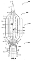
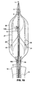
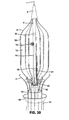
- a first embodiment of apparatus in accordance with the invention comprises a catheter assembly 50A (only the distal end region of which is shown), a thermal transfer device 60A connected to catheter assembly 50A and an associated stent capturing device 70A.
- Catheter assembly 50A comprises a low profile outer core catheter 8, having an inner movable core catheter 3, an inner stent-capturing sheath 19 situated over the outer core catheter 8, and an outer stent-receiving sheath 11.
- the thermal transfer device 60A comprises a frame assembly 62 to which an expandable balloon 4 is connected.
- Balloon 4 has a sleeve-type configuration, i.e., the balloon 4 has an annular cross-section along its entire length. As discussed below, this shape is advantageous since the flow of blood or other body fluid which normally occurs in the vessel will be maintained during inflation of the balloon through the opening 16 in the center of the balloon 4. As described below, the balloon is formed of material having suitable thermal transfer characteristics, i.e. relatively good heat conductivity.
- the frame assembly 62 includes a plurality of scaffolding wires 5, each wire 5 having a distal end molded into a conus 2, which has a tapered configuration for easy percutaneous insertion, and a proximal end 9 molded into the outer core catheter 8.
- the scaffolding wires are preferably formed of a material that exhibits superelastic properties.
- the outer core catheter 8 has a distal end which is situated proximally to the distal end of the inner core catheter 3 so that a projecting portion of the inner core catheter 3 extends beyond the distal end of the outer core catheter 8.
- Each of the scaffolding wires has one end fixed to the distal end of the projecting portion of the inner core catheter 3 at conus 2, another end fixed to the distal end of the outer core catheter 8, and a central region attached to the balloon 4.
- the frame assembly can be formed in other manners, such as by the use of elongate plastic members similarly affixed to the inner and outer core catheters.
- the sleeve-type balloon 4 is formed of a thin elastic sheet material of the type used for conventional balloon angioplasty catheters, such as polyethylene or other polymer film for example, having a thickness of about 25,4 ⁇ m (.001 inches), or other thin flexible biocompatible material having thermal transfer properties, sufficient for the present purpose.
- the balloon In expanded condition the balloon has an outer cylindrical wall 4a, an inner cylindrical wall 4b, and top and bottom walls 4c and 4d, together defining an interior chamber.
- the central regions of each of the six scaffolding wires 5 pass through narrow passages 5a formed in the outer surface of the outer wall 4a of balloon 4, to couple the frame assembly 62 to the balloon 4 as seen in FIG. 1 and as noted above, the frame 5 can be stretched and collapsed by advancing the movable inner core 3 forward while the outer core catheter 8 is fixed thereby radially collapsing balloon 4.
- the inner core catheter 3 has inflow and outflow fluid channels, formed in its wall extending from the proximal end of the catheter assembly to the distal end thereof. Inflow and outflow channels are fluidly connected at their distal ends to the interior chamber of balloon 4 by connecting inflow and outflow tubes 7 and 6 respectively.
- a pump or an infusion apparatus (not shown) is situated at the proximal end of the catheter assembly for circulating a thermal transfer fluid, such as a cold or hot saline liquid or gas (i.e. a fluid) at a temperature sufficient to achieve the transition temperature of the stent, into the chamber of balloon 4 through inflow fluid channel and inflow tube 7 to fill the chamber, and then out from the balloon chamber through outflow tube 6 and outflow fluid channel.
- a thermal transfer fluid such as a cold or hot saline liquid or gas (i.e. a fluid) at a temperature sufficient to achieve the transition temperature of the stent, into the chamber of balloon 4 through inflow fluid channel and inflow tube 7 to fill the chamber, and
- the inflow channel can be connected to a pressurized canister filled with a gas or liquid, hereinafter referred to as a thermal fluid, at a suitable temperature.
- a thermal fluid can also be injected by a syringe or by means of a pressure bag. Thermal fluid fills the balloon chamber and before this liquid or gas warms up inside the balloon, escapes into the outflow channel through outflow tube 6 and then to outside the patient at the other end of the system, where it may be collected in a bag (see FIG. 24a ). This allows persistent local maintenance of a desired temperature of the outer wall 4a of balloon 4 which constitutes a thermal transfer wall of the thermal transfer device.
- the stent-capturing device 70A comprises a plurality of resilient stent-capturing hooks 17 having hook portions 17a and shank portions 17b, molded into the wall of the stent capturing sheath 19 moveably situated over the outer core catheter 8.
- the hook portions 17A are normally spring biased outwardly to the positions shown in FIG. 1 .
- the resilient portions of the hooks 17 can be at least partially covered with a thin membrane 95 to facilitate safe and accurate capturing and holding of the stents as described below.
- the stent-receiving sheath 11 in its retracted position as seen in Figs. 1 and 2 has a flared end region 10.
- the hooks 17 can be opened or closed, i.e., the hook portions 17a moved radially outwardly or inwardly during deployment, retrieval or repositioning of an already deployed stent by advancing or withdrawing, respectively, the stent-receiving sheath 11 whereby the hook portions 17a are controllably engaged by the flared end region 10.
- the end region of the stent-receiving sheath 19 is in a closed condition in sealing engagement within a groove 2a formed in the conus 2.
- the tip assumes its flared configuration for facilitating the reception and subsequent removal of the collapsed stent ( FIG. 11h ).
- the system is introduced into the body with the frame assembly 62 and balloon 4 of thermal transfer device 60A in their collapsed condition and covered by the stent-receiving sheath 11.
- the inner core catheter 3 has a central lumen for receiving a guidewire 1 and two radiopaque markers 15 are provided on the moveable inner core catheter for precise positioning and operation under fluoroscopic guidance.
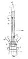
- FIG. 4-7 A first version of a second embodiment of the invention is illustrated in Figs. 4-7 .
- This embodiment is similar to the embodiment of Figs. 1-3 in that it includes a catheter assembly 50B, a thermal transfer device 60B and a stent-capturing device 70B operationally connected thereto.
- the second embodiment differs from the first embodiment mainly in that the thermal transfer device 60B comprises a solid-type balloon 12 rather than the sleeve-type balloon 4 of the first embodiment.
- the thermal transfer device 60B comprises a solid-type balloon 12 rather than the sleeve-type balloon 4 of the first embodiment.
- a transverse cross-section of the sleeve-type balloon 4 is an annulus
- the solid balloon has a circular disk-shaped transverse cross-section.
- the distal end of balloon 12 is sealingly connected to the introducing conus 2 or to the distal end of the inner core catheter 3, while the proximal end of balloon 12 is sealed to the more proximal aspect of the inner core catheter at 18 thereby defining a chamber.
- the balloon 12 is made of the same type of material as in the case of the first embodiment.
- the central region 12a of the balloon constitutes a thermal transfer wall as discussed below.
- the thermal transfer device also includes a frame assembly 62A comprising a plurality of scaffolding wires 5, the distal ends of which are molded in the conus 2 fixed to the distal end of the inner core catheter 3, the proximal ends of which are molded to the outer core catheter 8, and central regions of which extend through passages 5a formed in the outer surface of the balloon 12.
- the second embodiment of the invention shown in Figs. 4-7 also incorporates apparatus for circulating a thermal transfer fluid into and from the interior chamber of balloon 12. While the inner moveable core 3 has a central lumen for the guidewire 1 in the same manner as in the first embodiment, two continuous channels 13 and 14 are provided in the inner core 3. Channels 13 and 14 extend from the proximal end of the inner core catheter 3 and open at respective ports 13a and 14a situated within the chamber of balloon 12. Channel 14 is used for infusion of a thermal fluid into the chamber of balloon 12 while channel 13 is used as an outflow channel.
- a constant circulation of the thermal transfer fluid through the balloon 12 is achieved.
- the thermal fluid can recirculate through a closed circuit pump system.
- Inflow channel 14 and outflow channel 13 can be interchanged so that channel 14 is used for outflow while channel 13 is used for inflow.
- the thermal transfer device 60B can be collapsed in the same manner as thermal transfer device 60A by advancing the moveable core catheter 3 forwardly while holding the outer core 8 fixed.
- the thermal transfer device 60B can be collapsed by fixing the inner core catheter 3 in place and withdrawing the outer core catheter 8.
- the stent-capturing device 70B essentially corresponds to the stent-capturing device 70A.
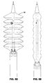
- FIG. 8 , 9 and 10 A second version of the second (solid balloon) embodiment is illustrated in Figs. 8 , 9 and 10 .
- This version essentially differs from the first version of the second embodiment in the construction of the thermal transfer fluid circulation system.
- the proximal end of balloon 12 is sealingly attached to the outer core catheter 8 at 18a and the space between the outer core catheter 8 and the inner movable core catheter 3 functions as an inflow channel for thermal fluid 25 which opens into the chamber defined by balloon 12.
- An outflow channel 13 is formed in inner core catheter 3 which terminates at a port 13a communicating with the balloon chamber. In this manner, one of the two channels in the inner core catheter 3 required in the first version of the second embodiment can be eliminated.
- FIG. 8a A modification of the second version of the second embodiment is shown in FIG. 8a , where the frame wires 5 are paired and interconnected with a single bridging bar 98 in their central portions.
- the stent-capturing sheath 19 with the capturing hooks are eliminated in this modification.
- there are at least four capturing wires 96 which are molded to the inner core catheter 3 at the base of conus 2.
- the capturing wires 96 extend parallel to the frame wires 5, but outside the balloon 12 and pass under the bridging bars 98 between the central portions of the paired frame wires 5.
- the relative motion of the movable core 3 and the outer core catheter 8 promotes opening and closing of the capturing wires 96. When the balloon 12 is expanded, capturing wires 96 open with it.
- the capturing wires 96 stay open and do not follow the collapsing balloon until the angled portion of the capturing wires become engaged with the bridging bars 98, which will facilitate closing of the capturing wires over the balloon.
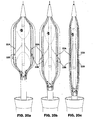
- FIG. 8b demonstrates another modification of the second version of the second embodiment.
- the balloon and frame are similar to the second version of the second embodiment, but the stent-capturing mechanism consists of four capturing wires 96 which are molded to the inner core catheter at the base of the conus 2.
- the capturing wires 96 extend parallel to the frame wires 5, but outside the balloon 12 and pass through the rings 97 attached to the central portions of the frame wires 5.
- the mechanism of opening and closing of the capturing wires 96 is similar to the one described in FIG. 8a with the only difference being that the capturing wires 96 pass through the rings 97 on the frame instead of extending under the bridging bars 98 between the parallel paired wires in FIG. 8a .
- FIG. 8c Yet another modification of the second version of the second embodiment is illustrated in FIG. 8c , where the solid type balloon does not have any metallic frame, but has an inflow channel 25 and an outflow channel 13, and can be expanded and collapsed by relative motion of the inner movable core 3 along the outer core catheter 8 in conjunction with injection of the thermal fluid under pressure.
- the embodiment shown in Figs. 8d and 8e is similar to the embodiment shown in Fig. 8c in that it incorporates a frameless balloon 12 that is expanded to the condition shown in FIG. 8d , and collapsed to the condition shown in FIG. 8e , through the relative motion of the inner movable core catheter within the outer core catheter in conjunction with controlling the circulation of the thermal transfer fluid.
- the stent capturing device e.g. hooks 17, which may be of the type shown in FIG. 8c .
- the embodiment of FIG. 8d includes a balloon 12 formed with an accordion-like wall construction. Specifically, the balloon 12 of the embodiment of FIG.
- FIG. 8d is formed with a wall 5 having a pleated or folded configuration.
- An accordion-like construction of the balloon reduces the stretching force required to collapse the balloon to the condition shown in Fig. 8e .
- This stretching force is generally large in the case where the balloon is formed of a minimally stretchable polymer material, such as PET.
- An accordion-like balloon structure therefore provides the flexibility of utilizing a wide range of materials for the balloon including stretchable polymers, such as polyurethanes, as well as minimally elastic polymers, such as PET. Additionally, the accordion-like structure increases the total thermal transfer area of the balloon.
- this type balloon can be provided with a frame for secure holding, capturing and repositioning/retrieval of the stents, similar to Fig.
- the thermal transfer device 60B comprises a balloon 12 having an outer wall 12a and an inner wall 40 attached to the inner surface of the outer wall 12a of the balloon at equally spaced locations, preferably at the wire sleeves 5a receiving the frame wires 5, as best seen in Fig 9d .
- the inner wall 40 and outer wall 12a of the balloon define an outer chamber 42 between them while the inner wall 40 defines an inner chamber 44.
- the inflow of a thermal fluid into the outer chamber 42 is provided through channel 32.
- the thermal fluid escapes into the inner chamber 44 of the balloon after being transiently trapped between the inner and outer layers of the balloon for more efficient thermal transfer through the outer balloon wall 12a.
- the thermal fluid then escapes into the space between the outer core catheter 8 and the movable core catheter 33 and is collected into an attached bag at the proximal end of the catheter assembly outside the patient. All other components of the system and mechanisms of its delivery/retrieval and operation remain the same as described above in the embodiments of FIGS. 4 , 5 , 6 and 7 .
- the systems comprising the sleeve type balloon ( FIGS. 1-3 ) and the solid type balloons ( FIGS. 4-10 ), provided with the stent-capturing hooks 17, are beneficial for primary delivery, repositioning or removal of stents including stent-graft devices or covered/coated stents.
- a clinical scenario of primary stent delivery and deployment into a focal narrowing 80a of a vessel 80 is shown in stages.
- the stent is formed in accordance with the method of the invention of either a one-way or two-way shape memory alloy having a first transition temperature at or below the body temperature.
- a stent is initially mounted on the thermal transfer device in its collapsed condition and so that the stent is in thermal transfer relationship with the collapsed thermal transfer device.
- the system is provided to the operator in a closed configuration (seen in FIG.11b ) in which the stent-receiving sheath 11 is in a forward position covering the collapsed stent 90, which has already been preloaded or mounted (such as by crimping) in contacting engagement over the collapsed balloon 12 and with the stent capturing hooks 17 secured to it.
- the closed configuration the distal end 11a of the stent-receiving sheath 11 is received in a groove 2a of conus 2 to seal the space within sheath 11 from the entry of blood or other body fluids in vessel 80 during delivery.
- the system is introduced into the vessel and positioned under direct fluoroscopic guidance (with the assistance of positioning markers 15) such that the position 11b of the delivery system with the premounted stent 90 is situated in the area of narrowing 80a of vessel 80 ( FIG.11b ).
- the stent-receiving sheath 11 at least partially thermally insulates the collapsed stent 90 from body heat thereby maintaining the temperature of the stent 90 below body temperature.
- deployment of stent 90 begins when the operator retracts or withdraws the stent-receiving sheath 11 exposing the collapsed stent 90 mounted on the collapsed balloon 12 to the vessel interior and to body heat (see FIG. 24b ).
- the circulation of a cold liquid or gas through the chamber of balloon 12 is started at about the same time as the sheath 11 is withdrawn.
- a cool saline solution is infused from the proximal end of the catheter assembly 50A through inflow channel 14 into the balloon chamber through port 14a and recirculates back through port 13a and outflow channel 13.
- the temperature of the stent 90 is thereby maintained below the transition temperature preventing premature expansion of the stent by the local transfer of thermal energy through the wall of the balloon 12 into the thermal transfer fluid.
- the balloon 12 remains in its collapsed position at this time by maintaining the outflow channel 13 open.
- a precise positioning of stent 90 is enabled by controlling the expansion of stent 90 through the circulation of cooling thermal fluid even after the sheath 11 is retracted and the stent is exposed to body temperature.
- the stent-capturing hooks 17 are opened and disconnected from stent 90 by further withdrawing of the stent-receiving sheath 11 with respect to the stent-capturing sheath 19, and the infusion of the cooling thermal fluid is stopped.
- the opened hooks are withdrawn toward the stent- receiving sheath before the stent expands to avoid interference with the stent as it expands.
- the stent 90 then warms naturally to body temperature through contact with surrounding blood or other body fluids or gas, and expands towards its original predetermined shape ( FIG.11d ).
- the stent is thus deployed into supporting engagement with the wall of vessel 80 and exerts an outward force against the wall to open the focal narrowing 80a of vessel 80.
- Balloon angioplasty of the deployed stent can then be performed if clinically indicated. This can be achieved by closing the outflow channel 13 with a provided stop-cock.
- the balloon is expanded by expansion of the frame assembly 62 and infusion of a contrast material diluted in normal saline through the infusion port 14a, which allows visualization of the balloon under real time radiological control ( FIG.11e ).
- Opening the frame assembly 62 is achieved by moving the outer core catheter 8 forward relative to inner core catheter 3 which helps expansion of the balloon 12.
- High pressure can be achieved inside the balloon 12, which is regulated and controlled by a pressure manometer connected to the inflow channel outside the patient.
- Angioplasty ( FIG.11e ) can be performed sequentially several times if so desired clinically.
- the balloon 12 is then deflated by opening the outflow channel 13 and the frame assembly 62 collapsed by moving the outer catheter 8 back ( FIG.11f ).
- the collapsed balloon is then withdrawn back into the stent-receiving sheath 11 whereupon the system can be removed from the body, leaving the stent in place ( FIG.11g ).
- this system can be used for deployment of stents exhibiting one-way or two-way memory.
- stents which are formed of shape-memory alloys that have a transition temperature greater than body temperature and which therefore expand to their predetermined configurations at temperatures higher than body temperature.
- a stent is delivered in the area of interest in the collapsed state covered with the outer sheath 11 and then exposed by moving the sheath 11 backwards. No infusion of cold thermal transfer fluid is needed to keep the stent in its collapsed state since the temperature of the stent will only rise to body temperature which is below the transition temperature.
- the stent therefore remains mounted on the collapsed balloon 12 secured to the catheter assembly by stent-capturing hooks.
- the stent-capturing hooks 17 are opened by further withdrawing of the stent-receiving sheath 11, releasing the stent 90 and the infusion of a warm solution at least at the transition temperature which is higher than body temperature is started through the inflow channel 14.
- the frame assembly 62 is opened by moving the outer core catheter 8 forward. These maneuvers allow expansion of the mounted stent inside the area of stenosis providing high radial force on the walls of the vessel due to its heating to the transformation or transition temperature. If clinically indicated a primary stent placement can be supplemented with a balloon angioplasty with the help of the same delivery system. This can be achieved by closing the outflow channel and infusion of a diluted contrast material through the inflow channel in the manner described above.
- the stent 90 is formed of a two-way shape memory alloy.
- the alloy may have a first transition temperature equal to or below body temperature, and a second lower transition temperature in the range of between -10°C to +35°C.
- the system is introduced with the balloon 12 in a collapsed state and covered with the stent-receiving outer sheath 11 ( FIG.12b ) and positioned at the desired location such that the collapsed balloon 12 is situated within the lumen of stent 90 that is intended to be retrieved or repositioned.
- the outer sheath 11 is withdrawn, the distal end 11a obtaining a flared configuration, thereby exposing the frame assembly 62A and the collapsed balloon 12 ( FIG.12c ).
- the metallic frame assembly is opened and the outer core catheter 8 advanced while the movable inner core catheter 3 is fixed in place ( FIG.12d ). Expansion of the frame assembly 62A brings the outer wall of balloon 12 into close contact with the stent.
- the infusion of a cold thermal fluid into the chamber of balloon 12 is started through the inflow channel 14 and the balloon 12 is inflated without creating high internal pressure within it due to an open outflow channel 13.
- the diameter of the open wire frame 62A matches the internal diameter of the stent and the cold balloon 12 moves into direct contact with the stent, causing its local cooling to the temperature at or below the second transition temperature, e.g. in the range of -10°C to 35°C, through the thermal transfer wall forming balloon 12.
- the stent becomes soft and pliable at this temperature and reduces at least somewhat in diameter to separate from the wall of vessel 80.
- the next step includes slowly stretching the wire frame 62 to a smaller diameter by moving the outer core catheter 8 backwards and keeping the movable core catheter 3 of the system in the same position. This maneuver causes a slow collapse of the frame assembly ( FIG.12e ). The infusion of cold thermal transfer fluid continues, but the balloon 12 moves away from the wall of the vessel 80 or other tubular structure due to stretching of the wire frame.
- the stent-capturing hooks 17 are maneuvered to close over the collapsed proximal end of the stent by suitable manipulation of the stent-capturing sheath 19 ( FIG.12f ).
- This causes secure fixation of the softened cooled stent to the catheter assembly.
- the stent is then drawn into the stent-receiving sheath 11 with a flared tip 11a and infusion of the cold solution/gas into the balloon 12 is terminated ( FIG.12g ). Collapse of the proximal end of the stent prevents migration of the device and slippage over the balloon due to persistent contact of the distal two thirds of the stent with the vessel wall, even though the entire stent becomes very soft.
- the stent can be then completely removed from the body or repositioned into the proper location ( FIG.12h ) while inside the stent-receiving sheath 11. In this latter case, the stent is then unsheathed ( FIG.12i ), warms to body temperature and then expands into the original shape and diameter after the stent-capturing hooks are released ( FIG.12j and FIG.12k ). The reposition and retrieval system is then removed from the body and the repositioned stent remains in place ( FIG.12l ).
- Stent retrieval is beneficial in patients where the indication for primary stent placement is an acute intimal dissection, where the stents are used as the vehicle for local delivery of medications or radioactive substances, or in the situations when repositioning of misplaced stent is required.
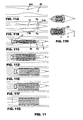
- the catheter assembly may be provided with a sleeve 110 formed, for example, of polymer material, which is advanced over the collapsed stent to cover the stent whereupon the entire system, i.e. the collapsed stent situated over the collapsed balloon, is pulled into the stent-receiving sheath 11.
- the sleeve 110 enables a smooth retraction of the stent and balloon into the sheath avoiding the possibility that the edges of the stent may catch on the wall of the stent receiving sheath 11.
- the sleeve 110 is supported by a stiff wire 112 that extends from the proximal end of the catheter assembly through the wall of sleeve 110 and which terminates at a circular snare 114 passing through and forming the open mouth of sleeve 110.
- the wire 112 is advanced to project the sleeve 110 from the position shown in FIG. 12m to that shown in FIG. 12n where the mouth of sleeve 110 is widened through appropriate manipulation of the wire 112 so that the mouth encircles the proximal end of the stent, and then to the position shown in FIG.
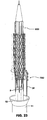
- the stent capturing device 70 comprises several hook members 120 connected to the frame wires 5 at each of the distal and proximal ends of the balloon.
- the hooks at the proximal end of the balloon extend in the proximal direction while the hooks at the distal end of the balloon extend in the distal direction.
- the catheter assembly is positioned at the location of the deployed stent and the frame expanded to bring the outer wall of balloon 12 into close contact with the stent.
- Cold thermal transfer fluid is infused into the chamber of balloon 12 causing the stent to cool to a temperature at or below the second transition temperature.
- the hooks 120 capture the stent as seen in FIG. 12q .
- the balloon and stent, captured by hooks 120 continue to collapse until reaching the condition shown in FIG. 12r . Since the stent is captured by the hooks at both its distal and proximal ends, the stent and balloon need not be withdrawn into the stent receiving sheath but can then be repositioned to the precise desired location in the condition shown in FIG. 12r .
- the flow of cold thermal fluid is discontinued allowing the stent to warm to body temperature and expand fully after releasing the holding hooks.
- the diameter of the stent can be reduced enough for safe repositioning, but the stent does not have to be collapsed completely because it does not have to be withdrawn into a small profile receiving sheath, like it is done for complete retrieval of the device. It is important to note that the stent can be initially delivered using a standard commercially available, modified or specifically designed delivery system used for the regular self-expanding stents.
- the same system can be used for retrieval or repositioning of a stent made from two-way shape memory alloy having a first transition temperature greater than body temperature and therefore a stent expanding to its original shape at higher than body temperature.
- These stents require cooling to a temperature below 37°C in order to exhibit second way memory and partially collapse for safe retrieval, with all other steps similar to the ones described in connection with FIG. 12 . If repositioning of such a stent is required after it has been recovered into the outer sheath, the position of the closed system is adjusted under direct fluoroscopic guidance. The mounted captured stent is unsheathed and stays in the collapsed state without infusion of a cold solution since the first transition temperature is greater than body temperature.
- the stent-capturing hooks are opened by completely withdrawing the stent-receiving sheath 11 , releasing the stent.
- a warm solution is infused into the balloon chamber through the infusion port 14a and the metallic frame 62 is opened by moving the outer core catheter forward along the fixed movable core.
- the steps of repositioning of such a stent are the same as for the primary delivery of the stent with the temperature of transformation, i.e. the transition temperature, higher than body temperature, which is described above and can be supplemented with an angioplasty in the same fashion if so desired clinically.
- a first version of a third embodiment of apparatus in accordance with the invention comprises a thermal transfer device 60C associated with a catheter assembly 50C and including a stent capturing device 70C.
- the thermal transfer device 60C comprises an inflatable and collapsible balloon 20 formed of the same type of material as that from which balloons 4 and 12 are made.
- the balloon 20 has a cloverleaf configuration in the cross sectional view ( FIG.14a ).
- Balloon sectors 20 1 -20 4 merge with each other at the proximal and distal ends of the balloon ( FIG.14 and FIG.15 ) and in the center of the balloon define radial spaces 20 1-4 , 20 1-2 , 20 2-3 and 20 3-4 between them ( FIG.14a ).
- Each of the radial spaces are formed by a pair of opposed radially and axially extending wall members 94 extending between the outer wall of balloon 20 and the inner core catheter 3.
- the distal end of the balloon is attached to the inner core catheter 3 at the attachment of the cone 2 and the proximal end of the balloon is molded to the more proximal portion of the inner core catheter 3 at point 18.
- the thermal transfer device 60C further includes a frame assembly 62C comprising four pairs of scaffolding wires 21, each wire having one end attached to the introducing conus 2, another end molded into the outer core catheter 8 at point 9 and a central region connected to balloon 20 by extending through passages 5a.
- the stent-capturing device 70C comprises capturing wire fingers 23 situated in respective radial spaces 20 1-4 , 20 1-2 , 20 2-3 and 20 3-4 , each of which has one end attached to inner core catheter 3 and extends at an angle from the core catheter 3 between adjacent pairs of radial sectors 20 1 -20 4 .
- a pair of connecting bars or bridging members 22a, 22b extend between each pair of the opposed walls 94 and captures a respective one of the capturing wires between them.
- each capturing wire finger 23 will be engaged by the bridging member 22a to automatically close the capturing wire finger.
- each capturing wire finger 23 will be engaged by a bridging member 22b to automatically open the capturing wire finger.
- inflow and outflow channels 14 and 13 are formed in the inner core catheter 3 having inflow and outflow ports 14a and 13a.
- FIG. 25 shows the proximal end of the system of the first version of the third embodiment shown in FIGS. 13-16 outside the patient, where the stent receiving sheath 11 has a side arm port 28 for flushing of heparinized saline to prevent thrombus formation in the space between the stent receiving sheath 11 and the outer core catheter 8.
- the outer core catheter 8 has a side port 28 for flushing of heparinized saline to prevent thrombus formation between the outer core catheter 8 and the inner movable core catheter 3, which itself has two side ports: one port 29 for inflow of solution/gas into the inflow channel 14 of balloon 20 and the other port 26 for outflow of a solution/gas from the outflow channel 13, which is connected to the bag (not shown).
- the proximal end of the cloverleaf balloon 20 is attached to the outer core catheter 8 at point 18a.
- a second version of the third embodiment of the invention is illustrated wherein the space between the outer core catheter 8 and the movable core catheter 3 is used as an inflow channel 25 for infusion of a thermal solution or gas into the balloon.
- the movable core 3 has a central lumen for the guidewire 1 and channel 13 for outflow of circulating thermal solution or gas. The rest of the design of this system is identical to the system of FIGS. 13-16 .
- FIGS. 20D-F illustrate a modification of the system wherein both inflow and outflow channels 25 and 31 are provided through the space defined between the outer core catheter 8 and the movable core catheter 3.
- the channels are separated by two dividing partitions that extend along the entire length of the catheter.
- FIG. 26 illustrates the proximal end of the system shown in FIGS. 17-20 outside the patient, where the stent receiving sheath 11 has a side arm port 28 for flushing of heparinized saline to prevent thrombus formation in the space between the stent receiving sheath 11 and the outer core catheter 8.
- the outer core catheter 8 has a side arm port 27 for infusion of a thermal fluid into the cloverleaf type balloon.
- the movable core catheter 3 has an opening of an outflow channel 26 from the balloon and is connected to the collecting bag (not shown). A stop-cock is placed on the outflow channel 26 and is closed in cases of performing a balloon angioplasty.
- FIG. 21 a clinical scenario of primary stent deployment using the cloverleaf balloon system of FIGS. 17-20 is shown for deploying a stent made of a shape memory allow having a transition temperature at or below body temperature.
- the collapsed stent covered with the outer sheath is positioned inside the area of focal narrowing of the vessel under fluoroscopic guidance ( FIG.21a ).
- the sheath is then withdrawn exposing the collapsed mounted stent and the infusion of a cold solution or gas is started immediately to control expansion of the stent ( FIG.21b ).
- the collapsed stent is secured with the capturing wires or fingers , which together with the local cooling prevent premature expansion of the device.
- the infusion of a cold thermal fluid is stopped and the metallic frame assembly is expanded by moving forward the outer core catheter along the fixed movable core ( FIG.21c ).
- This allows natural heating of the stent to body temperature and its expansion to the original shape and diameter inside the area of stenosis, providing high radial force on the walls of the vessel and opening the narrowed region of the vessel.
- the primary stent deployment can be supplemented with a balloon angioplasty under high pressure, which is achieved by closing the outflow channel 13 and infusion of a diluted contrast material via the inflow channel ( FIG.21d ).
- the pressure inside the balloon is regulated by the manometer attached to the inflow port outside the patient.
- the balloon is then deflated by stopping the infusion of the contrast material and opening the outflow channel , as well as collapsing the metallic frame by moving the movable core catheter forward along the fixed outer core catheter ( FIG.21e ). This maneuver also causes the stent-capturing fingers or wires to slide out of the cellular spaces in the stent, releasing the stent from the physical restraint ( FIG.21e ). The collapsed metallic frame and deflated balloon are then withdrawn back into the sheath and the entire system is removed from the body, leaving the stent in place ( FIG.21f ).
- the same system can be used for primary deployment of stents having a temperature of transformation higher than body temperature.
- stent is mounted on the balloon and delivered into the desired location inside the body covered with an outer sheath. It is then unsheathed, but does not expand until infusion of a warm solution at higher than body temperature is started via the inflow channel.
- the frame is then opened and the stent expands to its original shape and diameter, which it maintains after discontinuation of the infusion of a warm solution.
- the primary stent deployment can be supplemented with a balloon angioplasty in the same fashion as described above.
- the frame is then collapsed by moving the movable core forward along the fixed outer catheter, which provides sliding of the capturing wires out of the stent.
- the stent stays in place, exhibiting persistent radial force on the walls of the vessel or other tubular organ.
- the delivery system is then safely removed from the body.
- FIG. 22 the steps of 2-way shape memory stent retrieval with the cloverleaf balloon design are shown.
- the closed system is introduced and positioned inside the stent, which has to be removed ( FIG.22a ).
- the outer sheath is then withdrawn back and assumes a flared configuration after detaching from the introducing conus ( FIG.22b ).
- the metallic frame opens by advancing the outer core catheter along the fixed movable core and the cold thermal transfer fluid is infused into the balloon to cool the stent to the desired temperature, which is lower for stents with the first transition temperature at or below body temperature and higher (but still lower than body temperature) for stents with the first transition temperature above body temperature ( FIG.22c ).
- the outer core catheter 8 is then moved back while the movable core catheter 3 remains fixed in the same position, stretching the frame and collapsing the balloon.
- the stent, or at least its proximal end collapses with reduction in diameter of the frame 62c, while the stent-capturing wires 23 stay open nearly touching the vessel wall ( FIG.22d ).
- the stent, or at least its proximal end collapses over the stent capturing wires 23, which protrude through the cells of the stent.
- the stent capturing wires 23 remain open until they meet the cross bars 22 bridging the spaces between the sectors 20 1 -20 4 of balloon 20.
- the above described methods prevent any motion of the delivery system during deployment.
- the entire stent uniformly expands at the same time inside the area of narrowing, exerting radial force on the diseased wall of the vessel and restoring the normal lumen and flow.
- All current self-expanding stents have to be unsheathed gradually, exposing immediately expanding small segments of the device at a time. Persistent pulling back of the sheath during opening of the stent inside the vessel can cause slight forward or backward motion of the device, potentially leading to misplacement of the stent proximal or distal to the area of interest. This problem is eliminated by the system described above.
- FIG. 23 another device 70D for capturing the stent is illustrated.
- the stent As the stent is cooled by the thermal transfer device 60, and partially collapses, it is grabbed on the balloon by a snare loop 30.
- the loose snare loop 30 is advanced around the partially collapsed stent and then tightens into a smaller loop by sliding the thin catheter over it. This maneuver securely fixes the stent to the framed balloon and promotes further mechanical collapse of the stent for easy insertion into the outer sheath 11.
- the material of the balloon can be microporous as shown on Fig.33 .
- the balloon 5 may be formed of any suitable material, such as PET sheet material, in which micropores 200 are formed, such as by a laser.
- the size and number of the micropores can vary depending on the desired diffusion rate.
- a microporous balloon wall allows the cooling fluid to diffuse in very small quantities from inside the chamber to the outer surface of the balloon, providing more efficient transfer of temperature to the stent. This diffusion of the cooling fluid will not have any detectable systemic effect, but can promote fast and safe control of the stent temperature, regulating the crystal state of shape memory material. It is understood that any of the balloons described above can be constructed of microporous material.
- the catheter assembly in any of the above-described embodiments can include a balloon and circulation system of the type shown in Fig. 34 .
- the balloon 5 is attached to the inner core catheter 3 at the distal end and to the outer catheter 8 at the proximal end, with three channels provided inside the inner core catheter 3, i.e, one for a guide wire 1 and two for circulation of the thermal transfer fluid, providing inflow and outflow passages 14a, 13a.
- This embodiment can be utilized with any of the frame and stent-capturing arrangements described above.
- the thermal transfer device may comprise means for directly heating the heat transfer surface of the device.
- FIG. 27 illustrates a solid balloon system with multiple heating electrical resistance wires 34 provided on the surface of the balloon 12 to provide direct heating of the stent when an electrical current is passed through the wires.
- the wires 34 are connected to an electrical source outside the patient. This system can be beneficial for the deployment of stents having transition temperatures above body temperature.
- the outer surface of the solid balloon 12 is provided with an electromagnetic coil 48, which is heated by generation of an electrical current from application of an external magnetic field.
- the electromagnetic balloon can be used for deployment of stents having transition temperatures higher than body temperature by direct heating of the stent or by heating fluid injected into the balloon.
- the same system can be used for retrieval or repositioning of the stents with transformation temperatures greater than body temperature by infusing a cooling solution/gas into the balloon.
- first, second and third embodiments of the invention described above utilize thermal transfer fluid which is heated or cooled at the proximal end of the catheter assembly outside the body, other techniques for heating the thermal fluid may be employed.
- FIG. 29 illustrates a solid balloon system with an electromagnetic coil 49 inside the balloon (as opposed to outside the balloon as shown in FIG. 28 ) to provide heating of the fluid in the balloon chamber after application of an external magnetic field. It is applicable for the deployment, repositioning or retrieval of the stents with first transformation temperatures higher than body temperature.
- FIG. 30 illustrates a thermal transfer device provided with multiple optic fibers 47 inside the balloon for heating of the circulating fluid by a laser beam, which is connected to a source generator system on the proximal end outside the patient.
- the system can be used for the deployment, repositioning or retrieval of stents with first transformation temperatures higher than body temperature.
- optic fibers 46 are situated on the outer surface of the balloon and can be used for direct heating of the mounted stent or for heating of fluid circulating inside the balloon.
- the system can be used for the deployment, repositioning or retrieval of the stents with transition temperature higher than body temperature.
- FIG. 32 demonstrates another system with an ultrasound probe 51 inside the balloon, which provides fast heating of the circulating fluid for the deployment of stents with transition temperatures higher than body temperature.
- An ultrasound generator is connected to the system on the proximal end outside the patient.
- the system can be also used for repositioning or retrieval of the same stents by circulation of cooling thermal fluid inside the balloon.
- All currently available and all future stents and stent-grafts made from Nitinol or other materials with shape memory capabilities can be delivered with the above described systems and after training or heat/mechanical treatment can demonstrate second way memory effect, and can be retrieved from the body or repositioned into the desired location by using the systems that are described in this patent.
Abstract
Description
- The present invention generally relates to advanced medical endoluminal devices and methods of minimally invasive treatment of blockages of the blood vessels and other tubular organs. More particularly, the present invention relates to apparatus for delivering, repositioning and/or retrieving self-expanding stents for internal reinforcing of diseased tubular structure and/or for local delivery of pharmacological or radioactive agents having a beneficial advantage of reduction of re-stenosis.
- A stent is a generally longitudinal cylindrical device formed of biocompatible material, such as a metal or plastic, which is used in the treatment of stenosis, strictures, or aneurysms in body blood vessels and other tubular body structures, such as the esophagus, bile ducts, urinary tract, intestines or tracheo-bronchial tree. References hereafter to blood vessels and vessels will be understood to refer to all such tubular body structures. A stent is held in a reduced diameter state during its passage through a low profile catheter until delivered to the desired location in the blood vessel, whereupon the stent radially expands to an expanded diameter state in the larger diameter vessel to hold the vessel open. As discussed below, radial expansion of the stent may be accomplished by an inflatable balloon attached to a catheter, or the stent may be of the self-expanding type that will radially expand once deployed from the end portion of a delivery catheter.
- Non-diseased vessels that are stented have a tendency to develop more aggressive intimal hyperplasia than diseased vessels. Intimal hyperplasia is part of the endothelialization process by which the stent becomes incorporated into the vessel wall as a result of the vessel's reaction to a foreign body, and is characterized by deposition of cell layers covering the stent. It eventually results in formation of a neointima, which coats the stent and buries it completely in the vessel wall.
- Endothelialization generally improves patency rates and the more complete the apposition of the stent to the vessel wall, the more uniform and optimal is the degree of endothelialization. Of course, a fundamental concern is that the stent be deployed in the correct desired location in the vessel as precisely as possible in the first place. This is important when delivering radiation or medication to a particular location using the stent.
- Therefore, firstly, it is important that a stent be deployed in the correct desired position in the blood vessel and, secondly that the stent be as completely apposed to the vessel wall as possible.
- Stents fall into one of two categories based on their mechanism of deployment and radial expansion, namely, balloon-expandable stents and self-expanding stents.
- Balloon-expandable stents (BES) are mounted in their reduced diameter state on nylon or polyethylene balloons, usually by manual crimping, while others are available pre-mounted. One example of a BES is shown in
U.S. patent 4,733,665 to Palmaz . BES rely solely on balloon dilation to attain the desired expanded configuration or state. This enables BES to be deployed in a relatively controlled gradual manner. BES in general have more strength than self-expanding stents and initially resist deformation as well as recoil. BES behave elastically but eventually yield and become irreversibly, i.e. plastically, deformed under external force. Most BES are less flexible than self-expanding stents and are therefore less capable of being delivered through tortuous vessels and, when a BES is deployed in a tortuous vessel, it often straightens the vessel, forcing the vessel to conform to the shape of the stent rather than vice versa. This generally results in portions of the stent not being completely apposed to the vessel wall which in turn affects endothelialization and overall patency rate. - On the other hand, BES can generally be deployed in a relatively precise manner at the correct desired location in the vessel since they can be deployed in a controlled gradual manner by gradually controlling the inflation of the balloon. This ability to gradually control the expansion of the stent, along with the fact that BES rarely change their position on the balloon during inflation, enable fine adjustments to be made by the operator in the position of the stent within the vessel prior to stent deployment.
- Self-expanding stents (SES) are formed of braided stainless steel wire or shape-memory alloy such as nitinol and are generally delivered to desired locations in the body in a reduced diameter state in a low profile catheter while covered by an outer sheath which partially insulates the SES from body temperature and mechanically restrains them.
- Nitinol is an alloy comprised of approximately 50% nickel and 50% titanium. Nitinol has properties of superelasticity and shape memory. Superelasticity refers to the enhanced ability of material to be deformed without irreversible change in shape. Shape memory is the ability of a material to regain its shape after deformation at a lower temperature. These physical properties of nitinol allow complex device configurations and high expansion ratios enabling percutaneous delivery through low profile access systems.
- Superelasticity and shape memory are based on nitinol's ability to exist in two distinctly different, reversible crystal phases in its solid state at clinically useful temperatures. The alignment of crystals at the higher temperature is called the austenite (A) phase; the alignment of crystals at the lower temperature is called the martensite (M) phase. In between is a temperature interval of gradual transition between the A and M phases.
- Under external force, the shape of a nitinol device can be greatly deformed without irreversible damage. Depending on the temperature at which this external force is applied, superelastic or shape memory effects prevail. In close vicinity to or above the temperature defining transition into the full A state, superelasticity results: as soon as the deforming force is released, the device immediately assumes it original shape. When nitinol is deformed at or below the lower temperature of the complete M transition, the shape memory effect can be exploited. The device retains its deformed shape even after the external force is removed as long as the temperature of the environment stays below the temperature of transition into A phase. Only during heating does the device resume its original shape.
- While the shape memory effect is essentially a one-way type phenomena in which shape recovery occurs only upon heating the alloy to a temperature defining transition to the full A phase, by subjecting the alloy itself to a biasing force, i.e. an internal stress formed by dislocations introduced by plastic deformation in the alloy, a two-way shape memory can be imparted to the alloy so that cooling the alloy will induce a shape change.
- One type of self-expanding stent is constructed of wire formed of a shape-memory alloy, such as nitinol, having a transition temperature of about body temperature, i.e. 37°C. For example, reference is made to
U.S. patent 5,746,765 to Kleshinski et al. The one-way transition temperature is the temperature of transformation of a nitinol device from its collapsed state into a fully expanded configuration. The stent is pre-loaded on a low profile catheter by crimping the stent at room temperature (at which it can be plastically deformed) onto the catheter. An outer sheath covers the crimped stent and at least partially thermally insulates the stent as it is delivered to the desired location. Upon reaching the desired location, the sheath is withdrawn and the stent is exposed to body temperature whereupon it is naturally warmed to body temperature and expands to its expanded diameter state in supporting contact with the vessel wall. In a fully expanded state within the human body, the stent is capable of exerting considerable radial force on the surrounding structures, which allows mechanical opening of the vessel lumen and maintaining its long-term patentcy for free passage of flow. - If an alloy is used for which shape recovery occurs above body temperature, the SES must be heated after release into the body. If shape recovery occurs below body temperature, the device may be cooled during the delivery to prevent expansion inside the delivery catheter. If shape recovery occurs at body temperature, no heating or cooling is necessary during the delivery and deployment, provided delivery is relatively speedy. If, however, a tortuous iliac anatomy or other interference delays prompt deployment of a nitinol stent with these characteristics, premature warming to body temperature could cause expansion in the delivery sheath, increase friction, and interfere with delivery. In this instance, flushing with a cool solution has been suggested.
- SES do not require any special preparation prior to deployment. SES behave elastically throughout their lifetime, and do not become irreversibly deformed. When deployed, the nominal diameter is purposely selected to be greater that the diameter of the vessel. Therefore, once deployed, an SES exerts continuous outward force on the vessel as it tries to expand to its original dimensions. The ability of an SES to continuously exert an outward force on the vessel coupled with the greater flexibility of SES, generally results in optimal wall apposition, thereby optimizing endothelialization and improving patency rates. Nitinol self-expanding stents have been designed having good radial and hoop strength.
- However, while SES are preferable relative to BES in many applications with respect to achieving optimized endothelialization and increased patency rates, currently available methods for delivering and deploying SES are not entirely satisfactory. It has generally not been possible to deploy SES in the correct desired location in a vessel as precisely as in the case of BES with currently available delivery arrangements for the reason that the temperature of the SES rapidly increases to body temperature upon withdrawal of the outer sheath and therefore the stent quickly expands into engagement with the vessel wall. Consequently, there is not always enough time to finely adjust the position of the SES as it quickly expands, and it is not uncommon for the distal end of an SES, which is exposed to body temperature first, and which therefore expands before the rest of the SES, to engage and become attached to the vessel wall in the wrong position and in turn inhibit or prevent further adjustments in the position of the SES in the vessel.
- Another drawback in conventional methods for delivering and deploying SES, as compared to BES, is that during deployment while BES are advantageously pressed against the vessel wall with a relatively large outward force by the dilating balloon in the manner of an angioplasty to insure attachment of the BES to the vessel wall, SES must rely solely on the outward force exerted by the expanding SES to provide initial attachment. It is common to supplement the SES placement with a subsequent balloon angioplasty, which requires exchange of the stent delivery system after completion of stent deployment for a balloon catheter.
- Still another drawback in conventional methods for delivering and deploying SES is the possibility that when delivery is protracted, the SES is exposed to body temperature inside the delivery system. The deployment process can then become more difficult the device may open abruptly after being freed from the system and may jump beyond the target as the SE expands during deployment. BES cannot be repositioned or retrieved after deployment and while arrangements have been proposed for enabling the repositioning and/or retrieval of SES formed of two-way shape memory material, no practical workable arrangement has been developed.
- A malpositioned stent often requires an additional stent placement to correct the mistake and achieve the desired results. The stents will remain in the vessel for the entire life of the patient. In a high percentage of patients, the stent will become the site of recurrent stenosis due to an aggressive neointimal proliferation. These patients require repeated interventions, which often include balloon angioplasty and/or additional stent placement.
- The most striking illustration of these problems is seen in cardiac patients. Stents and balloon angioplasty transformed the care of patients with heart disease. Each year, about 700,000 patients in the U.S. undergo angioplasty, in which a balloon is used to clear an obstruction in a coronary artery and a stent is deployed to keep it open. Yet a disturbingly high 15% to 20% of the procedures fail within six months, due to the aggressive neointimal proliferation. These patients will often undergo further major treatments, which might be repeated several times.
- The need to be able to reposition and/or retrieve stents from a vessel also arises from the fact that heart researchers and stent manufacturers are developing a new generation of stents that not only prop open the vessel, but which deliver drugs to the site of the blockage in an effort to minimize or eliminate neointimal proliferation and keep the vessel open for long periods of time. Studies have shown that stents coated with a drug called rapamycin, essentially eliminates re-stenosis. Other medications, such as nitric oxide and paclitaxel or similar compounds, also have a potential to prevent proliferation of scar tissue by killing such cells. One concern is whether the drugs might work too well, inhibiting not only re-stenosis, but also the necessary growth of the thin layer of neointima. As previously described, this thin layer of cells, which grows over the stent, smoothes its surface (similar to a layer of Teflon), so blood cells can flow over it without damaging themselves. A damaged blood cell initiates a chemical cascade, which results in clot formation. Therefore an exposed bare metallic stent carries a risk of inducing thrombus formation within it.
- The potential of radioactive stents to prevent re-stenosis is an additional area of active research, since local radiation has been shown to inhibit the growth of neointima and halt the progression of atherosclerotic disease.
- One can therefore appreciate the benefit of being able to retrieve a stent used for local drug delivery or radiation treatment, after it has achieved its desired effect. This would eliminate potential risk of thrombus formation at the site of the exposed bare stent.
- In summary, ideally an optimal stent and associated delivery method should possess and combine all the positive traits mentioned so far in each of the stent categories. The stent should be pre-loaded on the delivery apparatus and should not require special preparation. It should be flexible to enhance apposition to the vessel wall. It should provide a controlled gradual deployment without stent migration to ensure deployment of the stent in the correct location. Lastly, in case of a malpositioned stent, or stent which is deployed for the purpose of its temporary effect, such as for local drug delivery, the system should have the option of enabling repositioning and/or retrieval of the stent.
- SES can be preloaded on the delivery apparatus, do not require special preparation and are flexible. However, to date, no satisfactory method or apparatus is available for obtaining a controlled gradual deployment of an SES without stent migration, or for repositioning and/or retrieving a SES. While methods have been suggested in the prior art for delivering SES to a correct location in a precise manner and for repositioning and retrieving SES formed of two-way shape memory material, these prior art arrangements all have drawbacks and have not been adopted in practice.
- A method for delivering, repositioning and/or retrieving an SES formed of a two-way shape memory alloy capable of expansion or collapsing in the radial direction in accordance with changes in temperature is disclosed in
U.S. patent 5,037,427 to Harada et al . According to Harada et al., a stent is made of nitinol alloy trained to have two-way shape memory. The stent is in an expanded diameter state at about body temperature and in a reduced diameter state at a temperature below body temperature. In delivering the stent, the stent is mounted in the reduced diameter state at the distal end of a catheter over a portion of the catheter having a number of side ports. Cooling water supplied through the catheter flows out from the side ports and is brought into contact with the stent during delivery to maintain the stent below body temperature and therefore in the reduced diameter state. When the SES is positioned at the desired location, the supply of the cooling water is stopped and the stent is warmed by the heat of the body and expands into supporting engagement with the wall of the vessel. The catheter is then withdrawn. In retrieving an already-positioned SES using this system, the distal end portion of the catheter is inserted into the expanded stent lumen and a cooling fluid is introduced into the catheter and discharged through the side ports at the distal end region into the vessel whereupon the stent is cooled and purportedly collapses onto the distal end portion of the catheter. The stent is retrieved by withdrawing the catheter. The patent suggests that the position of the stent can also be changed using this technique. -
U.S. Pat. No. 5,746,765 to Kleshinski, Simon, and Rabkin also discloses a stent made from an alloy with two-way shape memory, which expands inside the vessel due to natural heating to body temperature. The stent is covered with an elastic sleeve. When the metal frame is softened by decreased temperature, the sleeve overcomes its radial force and promotes its further contraction for easier retrieval. -
U.S. Pat. No. 6,077,298 to Tu et al . discloses a retractable stent made from a one-way shape-memory alloy, such as nitinol, that can be deployed into the body by means of dilation with a balloon catheter. For the stent retrieval, a radio frequency current within the range of 50 to 2,000 kHz must be applied directly to the stent to provide partial collapse of the stent after it is heated to a temperature above 43°C to 90°C. -
U.S. Pat. No. 5,961,547 to Razavi ,U.S. Pat. No. 5,716,410 to Wang et al .,U.S. Pat. No. 5,449,372 to Schwaltz et al . andU.S. Pat. No. 5,411,549 to Peters disclose temporary or retractable stents in the shape of a spiral coil or a double helix. Although these stents are made of different materials, such as metal or plastic, and have differences in the techniques of their deployment (heat-activated, self-expanding or balloon expandable), as well as methods of their retrieval (mechanical straightening vs. softening by increasing temperature vs. latch retraction), all of them have one common feature. The stents are connected with a wire extending outside the patient at all times and when they have to be removed, they are simply retracted back into the catheter with or without prior softening of the material. -
U.S. Patent No. 5,941,895 to Myler et al . discloses a removable cardiovascular stent with engagement hooks extending perpendicular to the axis of the stent into the vessel lumen. The stent retrieval technique requires introduction of an extraction catheter, which is adapted to grasp the engagement hooks of the stent with subsequent stent elongation in axial direction and reduction of its cross-sectional diameter. -
U.S. Patent No. 5,833,707 to McIntyre et al . discloses a stent formed from a thin sheet of metal that has been wound around itself into a general cylindrical tight roll and expands inside the body by heating to body temperature. This stent is designed for predominant use in the human urethra and is not suitable for cardiovascular applications due to very large metal surface that could be thrombogenic and increased size of the delivery system. The stent can be removed from the body with the help of a cannula or pincer grips for grasping the edge of the stent. By rotating the pinched stent, the pincer or cannula causes the stent to telescopically coil into smaller diameter, which can then be retrieved from the urethra. -
U.S. Patent No. 5,562,641 to Flomenblit et al . discloses a spiral or cylindrical stent made from alloy with two-way shape memory capabilities. The stent expands inside the body by heating to the temperature of 50°C to 80°C with an electric current, injection of hot fluid, external radio frequency irradiation or use of radio frequency antenna inside the catheter. The stent can be removed from the body after cooling to a temperature, ranging from -10°C to +20°C, at which the stent partially collapses in diameter and can be grasped with a catheter for retrieval. -
U.S. Patent No. 5,197,978 to Hess discloses a removable heat-recoverable tissue supporting device, especially a stent-like member. In this solution the stent is delivered and deployed by means of an angioplasty device by mechanical expansion without any control of the temperature of the stent. When it is desired to remove the stent, removal means is introduced including a tube portion and a gripping portion. Removal means is introduced by a catheter so that the gripping portion engages a portion of the stent. Subsequently, a warm fluid is pumped through tube portion to heat stent above the transition temperature of the alloy to cause the stent to purportedly reduce in diameter. However, the thermal transfer fluid inU.S. Patent No. 5,197,978 is infused directly into the body vessel. - Accordingly, it is an object of the present invention to provide new and improved apparatus for delivering stents to desired locations in blood vessels and other tubular body structures.
- Another object of the present invention is to provide new and improved apparatus for delivering self-expanding stents to desired locations in body vessels by which the stent can be deployed in a controlled gradual manner to thereby enhance the accuracy of positioning.
- Still another object of the present invention is to provide new and improved apparatus for delivering self-expanding stents to desired locations in body vessels by which the stent can be deployed in a controlled gradual manner safely without infusing a cooling liquid directly into the vessel or otherwise affecting general body temperature or causing systemic affects.
- Yet another object of the present invention is to provide new and improved apparatus for delivering self-expanding stents to desired locations in body vessels which eliminate the possibility of migration of the stent during deployment.
- A further object of the present invention is to provide new and improved apparatus for repositioning and/or retrieving self-expanding stents in and from a body vessel without infusing a cooling or heating liquid directly into the vessel or otherwise affecting general body temperature or causing systemic affects.
- A still further object of the present invention is to provide new and improved apparatus for repositioning and/or retrieving self-expanding stents which eliminates the possibility of migration of the stent during repositioning.
- A still further object of the present invention is to provide new and improved apparatus for providing supplemental balloon angioplasty after stent deployment with the same system, eliminating the need for exchanging catheters.
- Briefly, in accordance with one aspect of the present invention, these and other objects are attained by providing an apparatus for delivering a self-expanding stent formed of a shape memory alloy to a desired location in a body vessel by placing the stent in a collapsed condition in contact, or in other local heat transfer relationship, with a thermal transfer device coupled to a catheter assembly, and delivering the stent in its collapsed condition to the region of the desired location in the body vessel while in contact or other local heat transfer relationship with the thermal transfer device. According to the invention, the temperature of the thermal transfer device can be controlled in a safe and non-invasive matter so that the expansion of the stent can be controlled (thereby enabling the precise positioning of the stent) by suitably varying the temperature of the thermal transfer device, and therefore the stents, during delivery and/or deployment. The main features and principles of the invention are presented in
claim 1. - For example, in the case where the stent is made of a shape memory alloy having a transition temperature such that the stent from which it is formed is in its expanded diameter state at or slightly below body temperature (37°C), the temperature of the thermal transfer device is maintained below body temperature during delivery of the stent and at the beginning of deployment to allow precise positioning, while in the case where the stent is made of a shape memory alloy having a transition temperature such that the stent obtains its expanded diameter state at a temperature greater than body temperature, the temperature of the thermal transfer device is increased to the higher temperature after the stent in its collapsed state has been precisely positioned at the desired location whereupon the stent expands to its expanded diameter state.
- The thermal transfer device is constructed such that the temperature of the stent can be controlled quickly, precisely and non-invasively. Specifically, the temperature of the stent can be changed quickly since the stent is in local heat transfer relationship with the thermal transfer device. For present purposes, local heat transfer relationship means either the stent contacts the thermal device or the stent and thermal transfer device are sufficiently close, so that heat is transferred between the stent and the thermal transfer device without materially affecting the temperature of the surrounding tissue. The stent's temperature can be controlled relatively precisely since the temperature of the stent, which has a low mass, will essentially correspond to the temperature of the thermal transfer device, which has a much higher mass. Moreover, no liquid or gas will be infused directly into the vessel during the entire procedure.
- In preferred embodiments of the invention, the thermal transfer device comprises an arrangement itself capable of controlled radial expansion to about the diameter of a stent in its expanded diameter state, and contraction to a collapsed state. This feature, in some of its embodiments, is not only advantageous with respect to the initial delivery of a self-expanding stent with an option of performing a balloon angioplasty at the same time, but, additionally, makes the arrangement particularly adapted for repositioning and/or retrieving stents formed of two-way shape memory alloys that have already been deployed in a vessel, such as in the repositioning of a misplaced stent, removal of a stent placed for temporary indications, or the removal of a stent that has completed the delivery of medication or radiation to a particular area. Specifically, for removal and/or repositioning of the stent, the thermal transfer device is structured and arranged to be initially positioned in the lumen of the already deployed stent in a collapsed condition, out of contact or other local heat transfer relationship with the deployed stent, and then expanded into contact, or other local heat transfer relationship, with the stent. The temperature of the heat transfer device is adjusted so that the temperature of the deployed stent is reduced to that at which the stent obtains a relaxed, flexible state whereupon it separates from the vessel wall. The stent can then be drawn into the catheter assembly and either removed from the body or repositioned using the initial delivery process described above.
- In one embodiment, the thermal transfer device comprises an inflatable and expandable balloon member, formed of fluid impermeable or micro-porous material and the initial delivery of a stent formed of a shape memory alloy can be assisted in the manner of angioplasty by inflating the balloon to forcibly urge the stent against the vessel walls.
- In accordance with another aspect of the invention, the catheter assembly includes a capturing device for releasably coupling the stent to the catheter assembly during deployment, as well as for grasping an already-deployed stent for purposes of retrieval and/or repositioning. The capturing device prevents the stent from being carried away by the bloodstream or from migrating on the catheter, and is also structured and arranged to assist in drawing the stent in its flexible and pliable condition into the catheter assembly for repositioning and retrieval.
- In a preferred embodiment, the thermal transfer device comprises a balloon member connected to a catheter assembly defining a contained chamber having an outer wall, at least a part of which constitutes a thermal transfer material. The arrangement further includes apparatus for circulating a thermal transfer fluid from the proximal end region of the catheter assembly into the interior of the chamber and for providing an outflow of the thermal transfer fluid from the interior of the closed chamber to the proximal end region of the catheter assembly. As used herein, the term fluid refers to either a liquid or a gas. The temperature of the circulating thermal transfer fluid is controlled either by heating or cooling means situated at the proximal end of the catheter assembly outside of the body, or by heating means situated within the chamber of the thermal transfer device, such as optic fibers for transmitting a laser beam to heat the fluid circulating within the thermal transfer device, an internal ultrasound probe situated within the thermal transfer device, or a spiral resistance heating wire which will be heated by induction of an electric current by applying the power source or magnetic field from an external source. Alternatively, the surface of the balloon can be heated for direct heat transfer to the stent. For example, resistance heating wires may be situated on the outer surface of an expandable balloon, as can a spiral surface wire which can be heated by induction through the application of a power source or magnetic field from an external source, or externally situated optic fibers for transmitting a laser beam along and around the surface of the balloon. The stent is in contact with the heat transfer surface during delivery and depending on the transition temperature of the alloy from which the stent is made, the stent is either cooled, heated, or left at ambient temperature through contact or other local heat transfer relationship. In capturing an already deployed stent, the balloon in its collapsed condition is situated in the lumen of the already deployed stent, and then expanded into contact with the stent. Cooling liquid is circulated through the balloon which cools the stent causing it to separate from the vessel wall and to become flexible and pliable so that it can be drawn into the catheter assembly.
- In another preferred embodiment, the thermal transfer device comprises an expandable frame formed from a plurality of conductive resistance wires. The frame can be expanded by suitable adjustment of the catheter assembly to bow the resistance wires radially outwardly into contact with the stent. The wires are heated by connection to an external source of electricity and are in direct contact heat transfer relationship with the stent.
- A more complete appreciation of the present invention and many of the attendant advantages thereof will be readily understood by reference to the following detailed description when considered in connection with the accompanying drawings in which:
-
FIG. 1 is a perspective view of a first embodiment of a catheter assembly, including a first version of a hook-type stent capturing device, and an associated sleeve-type thermal transfer device in accordance with the invention, with the thermal transfer device shown in expanded condition; -
FIG. 2 is a perspective view of the first embodiment with the thermal transfer device in a collapsed condition; -
FIG. 3 is a perspective view of the first embodiment, partially broken away to show the hook-type stent capturing device of the catheter assembly for use in accordance with the invention; -
FIG. 4 is a perspective view of a first version of a second embodiment of a catheter assembly and associated solid thermal transfer device in an expanded condition for use in accordance with the invention, with a first version of an arrangement for circulating thermal transfer fluid through the thermal transfer device, and a hook-type stent capturing device; -
FIG. 5 is a perspective view of a first version of the second embodiment, partially broken away to show the first version of the circulation arrangement; -
FIG. 5a is a section view taken along line A-A ofFIG. 5 ; -
FIG. 5b is a section view taken along line B-B ofFIG 5 ; -
FIG. 6 is a transverse section view of the embodiment ofFIG. 5 through the stent-receiving sheath; -
FIG. 7 is a perspective view of the second embodiment with the thermal transfer device in a collapsed condition; -
FIG. 8 is a perspective view of a second version of the second embodiment, with a second version of the thermal transfer fluid circulating arrangement; -
FIG. 8a is perspective view of another version of the second embodiment, with a second version of a stent-capturing device; -
FIG. 8b is a perspective view of still another version of the second embodiment, with a third version of a stent-capturing device; -
FIG. 8c is a perspective view of yet another version of the second embodiment which does not utilize a frame assembly; -
FIG. 8d is a perspective view of another version of the second embodiment with the second version of the thermal transfer fluid circulation arrangement, which incorporates an accordian-like balloon construction shown in its expanded condition. -
FIG. 8e is a perspective view showing the embodiment ofFIG. 8d in a collapsed condition; -
FIG. 9 is a perspective view of the second version of the second embodiment, partially broken away to show the second version of the circulation arrangement; -
FIG. 9a is a section view taken along line A-A ofFIG. 9 ; -
FIG. 9b is a section view taken along line B-B ofFIG. 9 ; -
FIG. 9c is a perspective view of a modification of the second version of the second embodiment, but partially broken away to show the modification of the second version of the circulation arrangement; -
FIG. 9d is a section view taken along line D-D ofFIG. 9c ; -
FIG. 9e is a section view taken along line E-E ofFIG. 9c ; -
FIG. 10 is a perspective view of the second version of the second embodiment, with the thermal transfer device shown in a collapsed condition; -
FIGS. 11(a)-11(g) are seven perspective views showing sequential steps of operation of the first and second versions of the second embodiment of the invention in connection with the deployment of the stent; -
FIG. 11h shows two partial perspective views showing the sequence of withdrawal of the stent-receiving sheath from the conus; -
FIGS. 12(a)-12(l) are twelve perspective views showing sequential steps of operation of the first and second versions of the second embodiment of the invention in connection with repositioning and/or retrieving an already positioned stent; -
FIGS. 12(m)-(p) are perspective views showing the use of a stent-covering sleeve in connection with the retraction of a collapsed stent into a stent-receiving sheath; -
FIGS. 12(q) and 12(r) are perspective views of the second version of the second embodiment of the invention utilizing another version of a stent-capturing device specifically designed for use in repositioning the stent; -
FIG. 13 is a perspective view of a first version of a third embodiment of a catheter assembly, including another version of a stent capturing device, and associated sectored thermal transfer device in its expanded position for use in accordance with the invention, with the first version of a thermal transfer fluid circulation arrangement; -
FIG. 14 is a perspective view of the first version of the third embodiment, partially broken away to show the first version of the circulation arrangement; -
FIG. 14a is a section view taken along line A-A-FIG. 14 ; -
FIG. 14b is a section view taken along line B-B ofFIG. 14 ; -
FIG. 15 is a longitudinal sectional view of the first version of the third embodiment; -
FIGS. 16a-c are three perspective views showing sequential steps of the collapse of the first version of the third embodiment of the thermal transfer device from its expanded diameter condition; -
FIG. 17 is a perspective view of the second version of the third embodiment of the invention, with the second version of the thermal transfer fluid circulation arrangement; -
FIG. 18 is a perspective view of the second version of the third embodiment, partially broken away to show the second version of the circulation arrangement. -
FIG. 18a is a section view taken along line A-A ofFIG. 18 ; -
FIG. 18b is a section view taken along line B-B ofFIG. 18 ; -
FIG. 19 is a longitudinal section view of the second version of the third embodiment; -
FIGS. 20a-20c are three perspective views showing sequential steps of the collapse of the second version of the third embodiment of the thermal transfer device from its expanded diameter condition; -
FIG. 20d is a perspective view of a modification of the second version of the third embodiment, partially broken away to show the modification of the second version of the circulation arrangement; -
FIGS. 20e and 20f are section views of a modification of the second version of the third embodiment taken along lines E-E and F-F respectively inFIG. 20d ; -
FIGS. 21a-21f are six perspective views showing sequential steps of the operation of the second version of the third embodiment of the invention in connection with deploying a stent, and also illustrating the corresponding operation of the catheter assembly at its proximal end; -
FIGS. 22a-22g are seven perspective views showing sequential steps of the operation of the second version of the third embodiment of the invention in connection with retrieving the stent, and also illustrating the corresponding operation of the catheter assembly at its proximal end; -
FIG. 23 is a perspective view of the first embodiment for use in the invention with the thermal transfer device in a collapsed condition and including a snare-type stent capturing device; -
FIG. 24a is an elevation view of the entire third embodiment of the catheter assembly and associated sectored thermal transfer device; -
FIG. 24b is a perspective view of the third embodiment of the invention with a stent pre-mounted on the collapsed thermal transfer device; -
FIG. 25 is a perspective view of the proximal end of the catheter assembly of the first version of the third embodiment of the invention; -
FIG. 26 is a perspective view of the proximal end of the catheter assembly of the second version of the third embodiment of the invention; -
FIG. 27 is a perspective view of a fourth embodiment of the catheter assembly and associated thermal transfer device for use in accordance with the invention; -
FIG. 28 is a perspective view of a fifth embodiment of a catheter assembly and associated thermal transfer device for use in accordance with the invention; -
FIG. 29 is a perspective view of a sixth embodiment of a catheter assembly and associated thermal transfer device for use in accordance with the invention; -
FIG. 30 is a perspective view of a seventh embodiment of a catheter assembly and associated thermal transfer device for use in accordance with the invention; -
FIG. 31 is a perspective view of an eighth embodiment of a catheter assembly and associated thermal transfer device for use in accordance with the invention; -
FIG. 32 is a perspective view of a ninth embodiment of a catheter assembly and associated thermal transfer device for use in accordance with the invention; -
Fig.33 is perspective view of a modified second embodiment of a catheter assembly with a balloon made of a microporous material, allowing diffusion of a thermal fluid to the outer surface of the balloon; -
Fig.34 is a perspective view of a second version of the second embodiment of a balloon assembly with the first version of the thermal fluid circulation arrangement. - Various embodiments of apparatus for delivering a self-expanding stent and/or for retrieving and repositioning an already-positioned self-expanding stent in accordance with the invention are described herein. In all cases, where the apparatus is to be used for delivering a stent, the stent is formed of a shape memory material having a two-way shape memory. Additionally, in the case where the apparatus is to be used for retrieving and/or repositioning a stent that is already in place, the stent must be formed of a two-way shape memory alloy.
- For purposes of describing the invention, except where noted, the stent to be delivered, retrieved and/or repositioned is formed of a two-way shape memory material having or trained to have a second cold memory. When released into the vessel or other tubular structure and naturally warmed to first transition temperature at or below body temperature of 37°C, the stent expands and recovers its previously imprinted intended functional shape at or below body temperature. In a fully expanded state within the human body, the stent is capable of exerting considerable radial force on the surrounding structures, which allows mechanical opening of the vessel lumen and maintaining its long-term patency for free passage of flow. When the fully expanded stent is cooled to a temperature in the range of -10°C to +35°C , it becomes compliant, has a reduced stress state, and can be compressed into a reduced diameter, small enough to fit within a low profile delivery system for percutaneous insertion.
- The stent is constructed of a single continuous thermal shape memory wire, can be cut with laser technology, or formed with a photoetching technique from thermal shape memory tubing to create a mesh-like configuration. The expansive force and the stiffness along the length of the stent can be modulated by changes in the dimensions of the cell geometry. There are no open or sharp edges at either end of the device. This prevents injury to the wall while improving the ability to position, reposition or retrieve the device. Because the wire never overlaps itself, the stent wall thickness is never greater than the wire diameter and both surfaces are smooth. The cells of the stent create an open mesh, which is favorable for maintaining the patency of side branches, and also minimizes the length changes, which occur between the collapsed and expanded forms of the device. The shortening of the stent during its expansion depends on the cell geometry, but usually does not exceed 10% of the length of the stent in its completely expanded state. In a preferred embodiment, an intraluminal medical device may include a permanent or temporary implantable stent or stent-graft, a permanent or temporary device impregnated with medications or radioactivity for local therapy, or a temporary retrievable/repositionable device.
- For the purpose of non-surgical treatment of vascular aneurysms, acutely bleeding vessels, or other perforated tubular organs (GI tract, bile ducts, tracheo-bronchial tree etc.), the stent can be covered with a graft material or coating. The graft material is anchored at each end to an exposed section of the metallic scaffold of the stent. The design of the device is such that length changes that occur during delivery can be largely limited to the short uncovered stent segments at either end of the device. The stents can also be impregnated with certain medications or provided with a radioactive coating, for local delivery of drugs or radiation to the diseased vessel.
- Referring now to the drawings in which like reference characters designate identical or corresponding parts throughout the several views, and more particularly to
Figs. 1-3 , a first embodiment of apparatus in accordance with the invention comprises acatheter assembly 50A (only the distal end region of which is shown), athermal transfer device 60A connected tocatheter assembly 50A and an associatedstent capturing device 70A.Catheter assembly 50A comprises a low profileouter core catheter 8, having an innermovable core catheter 3, an inner stent-capturingsheath 19 situated over theouter core catheter 8, and an outer stent-receivingsheath 11. In this embodiment, thethermal transfer device 60A comprises aframe assembly 62 to which anexpandable balloon 4 is connected.Balloon 4 has a sleeve-type configuration, i.e., theballoon 4 has an annular cross-section along its entire length. As discussed below, this shape is advantageous since the flow of blood or other body fluid which normally occurs in the vessel will be maintained during inflation of the balloon through theopening 16 in the center of theballoon 4. As described below, the balloon is formed of material having suitable thermal transfer characteristics, i.e. relatively good heat conductivity. - The
frame assembly 62 includes a plurality ofscaffolding wires 5, eachwire 5 having a distal end molded into aconus 2, which has a tapered configuration for easy percutaneous insertion, and aproximal end 9 molded into theouter core catheter 8. The scaffolding wires are preferably formed of a material that exhibits superelastic properties. - The
outer core catheter 8 has a distal end which is situated proximally to the distal end of theinner core catheter 3 so that a projecting portion of theinner core catheter 3 extends beyond the distal end of theouter core catheter 8. Each of the scaffolding wires has one end fixed to the distal end of the projecting portion of theinner core catheter 3 atconus 2, another end fixed to the distal end of theouter core catheter 8, and a central region attached to theballoon 4. - It will be seen that by relative movement of the inner and outer core catheters to shorten the projecting portion of the inner core, the
wires 5 will bow or bend and therefore expand the balloon to its expanded condition shown inFIG. 1 . On the other hand, relative movement of the inner and outer core catheters to lengthen the projecting portion of the inner core straightens the wires and collapses the balloon to its collapsed condition as seen inFIG. 2 . The frame assembly can be formed in other manners, such as by the use of elongate plastic members similarly affixed to the inner and outer core catheters. - The sleeve-
type balloon 4 is formed of a thin elastic sheet material of the type used for conventional balloon angioplasty catheters, such as polyethylene or other polymer film for example, having a thickness of about 25,4 µm (.001 inches), or other thin flexible biocompatible material having thermal transfer properties, sufficient for the present purpose. In expanded condition the balloon has an outer cylindrical wall 4a, an inner cylindrical wall 4b, and top and bottom walls 4c and 4d, together defining an interior chamber. The central regions of each of the sixscaffolding wires 5 pass throughnarrow passages 5a formed in the outer surface of the outer wall 4a ofballoon 4, to couple theframe assembly 62 to theballoon 4 as seen inFIG. 1 and as noted above, theframe 5 can be stretched and collapsed by advancing the movableinner core 3 forward while theouter core catheter 8 is fixed thereby radially collapsingballoon 4. - The
inner core catheter 3 has inflow and outflow fluid channels, formed in its wall extending from the proximal end of the catheter assembly to the distal end thereof. Inflow and outflow channels are fluidly connected at their distal ends to the interior chamber ofballoon 4 by connecting inflow andoutflow tubes balloon 4 through inflow fluid channel andinflow tube 7 to fill the chamber, and then out from the balloon chamber throughoutflow tube 6 and outflow fluid channel. The term fluid is used herein in its broad sense and comprises both liquids and gases. - Alternatively, the inflow channel can be connected to a pressurized canister filled with a gas or liquid, hereinafter referred to as a thermal fluid, at a suitable temperature. Thermal fluid can also be injected by a syringe or by means of a pressure bag. Thermal fluid fills the balloon chamber and before this liquid or gas warms up inside the balloon, escapes into the outflow channel through
outflow tube 6 and then to outside the patient at the other end of the system, where it may be collected in a bag (seeFIG. 24a ). This allows persistent local maintenance of a desired temperature of the outer wall 4a ofballoon 4 which constitutes a thermal transfer wall of the thermal transfer device. - As seen in
FIGS.1-3 , the stent-capturingdevice 70A comprises a plurality of resilient stent-capturinghooks 17 having hook portions 17a and shank portions 17b, molded into the wall of thestent capturing sheath 19 moveably situated over theouter core catheter 8. Thehook portions 17A are normally spring biased outwardly to the positions shown inFIG. 1 . The resilient portions of thehooks 17 can be at least partially covered with athin membrane 95 to facilitate safe and accurate capturing and holding of the stents as described below. The stent-receivingsheath 11 in its retracted position as seen inFigs. 1 and2 has a flaredend region 10. Thehooks 17 can be opened or closed, i.e., the hook portions 17a moved radially outwardly or inwardly during deployment, retrieval or repositioning of an already deployed stent by advancing or withdrawing, respectively, the stent-receivingsheath 11 whereby the hook portions 17a are controllably engaged by the flaredend region 10. - As seen in
FIGS. 11b and 11h , when the catheter assembly is introduced into the body, the end region of the stent-receivingsheath 19 is in a closed condition in sealing engagement within a groove 2a formed in theconus 2. When the stent-receiving sheath is withdrawn to expose a preloaded stent or balloon, the tip assumes its flared configuration for facilitating the reception and subsequent removal of the collapsed stent (FIG. 11h ). - As described below in connection with
Figs. 11 and12 , the system is introduced into the body with theframe assembly 62 andballoon 4 ofthermal transfer device 60A in their collapsed condition and covered by the stent-receivingsheath 11. As seen inFIGS. 1-3 theinner core catheter 3 has a central lumen for receiving aguidewire 1 and tworadiopaque markers 15 are provided on the moveable inner core catheter for precise positioning and operation under fluoroscopic guidance. - A first version of a second embodiment of the invention is illustrated in
Figs. 4-7 . This embodiment is similar to the embodiment ofFigs. 1-3 in that it includes acatheter assembly 50B, athermal transfer device 60B and a stent-capturingdevice 70B operationally connected thereto. The second embodiment differs from the first embodiment mainly in that thethermal transfer device 60B comprises a solid-type balloon 12 rather than the sleeve-type balloon 4 of the first embodiment. In other words, while a transverse cross-section of the sleeve-type balloon 4 is an annulus, the solid balloon has a circular disk-shaped transverse cross-section. The distal end ofballoon 12 is sealingly connected to the introducingconus 2 or to the distal end of theinner core catheter 3, while the proximal end ofballoon 12 is sealed to the more proximal aspect of the inner core catheter at 18 thereby defining a chamber. Theballoon 12 is made of the same type of material as in the case of the first embodiment. The central region 12a of the balloon constitutes a thermal transfer wall as discussed below. Like the first embodiment, the thermal transfer device also includes aframe assembly 62A comprising a plurality ofscaffolding wires 5, the distal ends of which are molded in theconus 2 fixed to the distal end of theinner core catheter 3, the proximal ends of which are molded to theouter core catheter 8, and central regions of which extend throughpassages 5a formed in the outer surface of theballoon 12. - The second embodiment of the invention shown in
Figs. 4-7 also incorporates apparatus for circulating a thermal transfer fluid into and from the interior chamber ofballoon 12. While the innermoveable core 3 has a central lumen for theguidewire 1 in the same manner as in the first embodiment, twocontinuous channels inner core 3.Channels inner core catheter 3 and open atrespective ports balloon 12.Channel 14 is used for infusion of a thermal fluid into the chamber ofballoon 12 whilechannel 13 is used as an outflow channel. By suitably connecting the proximal end ofchannel 14 to a pump, or other source of infusion of thermal fluid, and by suitably connecting the proximal end ofchannel 13 to a collecting container, a constant circulation of the thermal transfer fluid through theballoon 12 is achieved. Alternatively, the thermal fluid can recirculate through a closed circuit pump system.Inflow channel 14 andoutflow channel 13 can be interchanged so thatchannel 14 is used for outflow whilechannel 13 is used for inflow. - Referring to
FIG. 7 , as described below in connection withFigs. 11 and12 , thethermal transfer device 60B can be collapsed in the same manner asthermal transfer device 60A by advancing themoveable core catheter 3 forwardly while holding theouter core 8 fixed. Alternatively, thethermal transfer device 60B can be collapsed by fixing theinner core catheter 3 in place and withdrawing theouter core catheter 8. The stent-capturingdevice 70B essentially corresponds to the stent-capturingdevice 70A. - A second version of the second (solid balloon) embodiment is illustrated in
Figs. 8 ,9 and10 . This version essentially differs from the first version of the second embodiment in the construction of the thermal transfer fluid circulation system. The proximal end ofballoon 12 is sealingly attached to theouter core catheter 8 at 18a and the space between theouter core catheter 8 and the innermovable core catheter 3 functions as an inflow channel forthermal fluid 25 which opens into the chamber defined byballoon 12. Anoutflow channel 13 is formed ininner core catheter 3 which terminates at aport 13a communicating with the balloon chamber. In this manner, one of the two channels in theinner core catheter 3 required in the first version of the second embodiment can be eliminated. - A modification of the second version of the second embodiment is shown in
FIG. 8a , where theframe wires 5 are paired and interconnected with asingle bridging bar 98 in their central portions. The stent-capturingsheath 19 with the capturing hooks are eliminated in this modification. Instead, there are at least four capturingwires 96, which are molded to theinner core catheter 3 at the base ofconus 2. The capturingwires 96 extend parallel to theframe wires 5, but outside theballoon 12 and pass under the bridging bars 98 between the central portions of the pairedframe wires 5. The relative motion of themovable core 3 and theouter core catheter 8 promotes opening and closing of the capturingwires 96. When theballoon 12 is expanded, capturingwires 96 open with it. When the balloon is slowly deflated, the capturingwires 96 stay open and do not follow the collapsing balloon until the angled portion of the capturing wires become engaged with the bridging bars 98, which will facilitate closing of the capturing wires over the balloon. -
FIG. 8b demonstrates another modification of the second version of the second embodiment. The balloon and frame are similar to the second version of the second embodiment, but the stent-capturing mechanism consists of four capturingwires 96 which are molded to the inner core catheter at the base of theconus 2. The capturingwires 96 extend parallel to theframe wires 5, but outside theballoon 12 and pass through the rings 97 attached to the central portions of theframe wires 5. The mechanism of opening and closing of the capturingwires 96 is similar to the one described inFIG. 8a with the only difference being that the capturingwires 96 pass through the rings 97 on the frame instead of extending under the bridging bars 98 between the parallel paired wires inFIG. 8a . - Yet another modification of the second version of the second embodiment is illustrated in
FIG. 8c , where the solid type balloon does not have any metallic frame, but has aninflow channel 25 and anoutflow channel 13, and can be expanded and collapsed by relative motion of the innermovable core 3 along theouter core catheter 8 in conjunction with injection of the thermal fluid under pressure. - The embodiment shown in
Figs. 8d and 8e is similar to the embodiment shown inFig. 8c in that it incorporates aframeless balloon 12 that is expanded to the condition shown inFIG. 8d , and collapsed to the condition shown inFIG. 8e , through the relative motion of the inner movable core catheter within the outer core catheter in conjunction with controlling the circulation of the thermal transfer fluid. Not shown for purposes of clarity is the stent capturing device, e.g. hooks 17, which may be of the type shown inFIG. 8c . Unlike the smooth-walled balloon 12 of the embodiment ofFIG. 8c , the embodiment ofFIG. 8d includes aballoon 12 formed with an accordion-like wall construction. Specifically, theballoon 12 of the embodiment ofFIG. 8d is formed with awall 5 having a pleated or folded configuration. An accordion-like construction of the balloon reduces the stretching force required to collapse the balloon to the condition shown inFig. 8e . This stretching force is generally large in the case where the balloon is formed of a minimally stretchable polymer material, such as PET. An accordion-like balloon structure therefore provides the flexibility of utilizing a wide range of materials for the balloon including stretchable polymers, such as polyurethanes, as well as minimally elastic polymers, such as PET. Additionally, the accordion-like structure increases the total thermal transfer area of the balloon. Alternatively this type balloon can be provided with a frame for secure holding, capturing and repositioning/retrieval of the stents, similar toFig. 8a and8b . Other stent-capturing devices may be utilized. The design of the accordion-shaped balloon is advantageous since it significantly decreases the forces required to stretch and collapse a balloon. Referring toFigs. 9c-9e , a modification of the second solid balloon embodiment of the invention is illustrated. In this embodiment, thethermal transfer device 60B comprises aballoon 12 having an outer wall 12a and aninner wall 40 attached to the inner surface of the outer wall 12a of the balloon at equally spaced locations, preferably at thewire sleeves 5a receiving theframe wires 5, as best seen inFig 9d . Theinner wall 40 and outer wall 12a of the balloon define anouter chamber 42 between them while theinner wall 40 defines aninner chamber 44. The inflow of a thermal fluid into theouter chamber 42 is provided throughchannel 32. There are multiple perforations in theinner wall 40 of the balloon, and the thermal fluid escapes into theinner chamber 44 of the balloon after being transiently trapped between the inner and outer layers of the balloon for more efficient thermal transfer through the outer balloon wall 12a. The thermal fluid then escapes into the space between theouter core catheter 8 and themovable core catheter 33 and is collected into an attached bag at the proximal end of the catheter assembly outside the patient. All other components of the system and mechanisms of its delivery/retrieval and operation remain the same as described above in the embodiments ofFIGS. 4 ,5 ,6 and7 . - The systems comprising the sleeve type balloon (
FIGS. 1-3 ) and the solid type balloons (FIGS. 4-10 ), provided with the stent-capturinghooks 17, are beneficial for primary delivery, repositioning or removal of stents including stent-graft devices or covered/coated stents. - Referring to
FIG. 11 , a clinical scenario of primary stent delivery and deployment into a focal narrowing 80a of avessel 80 is shown in stages. The stent is formed in accordance with the method of the invention of either a one-way or two-way shape memory alloy having a first transition temperature at or below the body temperature. In utilizing the apparatus described above for primary stent delivery, a stent is initially mounted on the thermal transfer device in its collapsed condition and so that the stent is in thermal transfer relationship with the collapsed thermal transfer device. Preferably, the system is provided to the operator in a closed configuration (seen inFIG.11b ) in which the stent-receivingsheath 11 is in a forward position covering thecollapsed stent 90, which has already been preloaded or mounted (such as by crimping) in contacting engagement over thecollapsed balloon 12 and with the stent capturing hooks 17 secured to it. In the closed configuration, the distal end 11a of the stent-receivingsheath 11 is received in a groove 2a ofconus 2 to seal the space withinsheath 11 from the entry of blood or other body fluids invessel 80 during delivery. - The system is introduced into the vessel and positioned under direct fluoroscopic guidance (with the assistance of positioning markers 15) such that the position 11b of the delivery system with the
premounted stent 90 is situated in the area of narrowing 80a of vessel 80 (FIG.11b ). During this delivery, the stent-receivingsheath 11 at least partially thermally insulates thecollapsed stent 90 from body heat thereby maintaining the temperature of thestent 90 below body temperature. - Referring to
FIG.11c , deployment ofstent 90 begins when the operator retracts or withdraws the stent-receivingsheath 11 exposing thecollapsed stent 90 mounted on thecollapsed balloon 12 to the vessel interior and to body heat (seeFIG. 24b ). The circulation of a cold liquid or gas through the chamber ofballoon 12 is started at about the same time as thesheath 11 is withdrawn. For example a cool saline solution is infused from the proximal end of thecatheter assembly 50A throughinflow channel 14 into the balloon chamber throughport 14a and recirculates back throughport 13a andoutflow channel 13. The temperature of thestent 90 is thereby maintained below the transition temperature preventing premature expansion of the stent by the local transfer of thermal energy through the wall of theballoon 12 into the thermal transfer fluid. Theballoon 12 remains in its collapsed position at this time by maintaining theoutflow channel 13 open. A precise positioning ofstent 90 is enabled by controlling the expansion ofstent 90 through the circulation of cooling thermal fluid even after thesheath 11 is retracted and the stent is exposed to body temperature. When the operator is satisfied that thestent 90 is precisely positioned in the desired location 80a of the focal narrowing ofvessel 80, the stent-capturinghooks 17 are opened and disconnected fromstent 90 by further withdrawing of the stent-receivingsheath 11 with respect to the stent-capturingsheath 19, and the infusion of the cooling thermal fluid is stopped. The opened hooks are withdrawn toward the stent- receiving sheath before the stent expands to avoid interference with the stent as it expands. Thestent 90 then warms naturally to body temperature through contact with surrounding blood or other body fluids or gas, and expands towards its original predetermined shape (FIG.11d ). The stent is thus deployed into supporting engagement with the wall ofvessel 80 and exerts an outward force against the wall to open the focal narrowing 80a ofvessel 80. - Balloon angioplasty of the deployed stent can then be performed if clinically indicated. This can be achieved by closing the
outflow channel 13 with a provided stop-cock. The balloon is expanded by expansion of theframe assembly 62 and infusion of a contrast material diluted in normal saline through theinfusion port 14a, which allows visualization of the balloon under real time radiological control (FIG.11e ). Opening theframe assembly 62 is achieved by moving theouter core catheter 8 forward relative toinner core catheter 3 which helps expansion of theballoon 12. High pressure can be achieved inside theballoon 12, which is regulated and controlled by a pressure manometer connected to the inflow channel outside the patient. Angioplasty (FIG.11e ) can be performed sequentially several times if so desired clinically. - The
balloon 12 is then deflated by opening theoutflow channel 13 and theframe assembly 62 collapsed by moving theouter catheter 8 back (FIG.11f ). The collapsed balloon is then withdrawn back into the stent-receivingsheath 11 whereupon the system can be removed from the body, leaving the stent in place (FIG.11g ). As noted above, this system can be used for deployment of stents exhibiting one-way or two-way memory. - The same system can be used for delivery and precise positioning of stents which are formed of shape-memory alloys that have a transition temperature greater than body temperature and which therefore expand to their predetermined configurations at temperatures higher than body temperature. Such a stent is delivered in the area of interest in the collapsed state covered with the
outer sheath 11 and then exposed by moving thesheath 11 backwards. No infusion of cold thermal transfer fluid is needed to keep the stent in its collapsed state since the temperature of the stent will only rise to body temperature which is below the transition temperature. The stent therefore remains mounted on thecollapsed balloon 12 secured to the catheter assembly by stent-capturing hooks. When the position of the device is adjusted and the desired location of the stent is confirmed, the stent-capturinghooks 17 are opened by further withdrawing of the stent-receivingsheath 11, releasing thestent 90 and the infusion of a warm solution at least at the transition temperature which is higher than body temperature is started through theinflow channel 14. Theframe assembly 62 is opened by moving theouter core catheter 8 forward. These maneuvers allow expansion of the mounted stent inside the area of stenosis providing high radial force on the walls of the vessel due to its heating to the transformation or transition temperature. If clinically indicated a primary stent placement can be supplemented with a balloon angioplasty with the help of the same delivery system. This can be achieved by closing the outflow channel and infusion of a diluted contrast material through the inflow channel in the manner described above. - Referring to
FIG. 12 , a clinical scenario is given when thestent 90 has been malpositioned inside the vessel only partially covering the area of stenosis (FIG.12a ) and it is desired to reposition the stent. In this case, thestent 90 is formed of a two-way shape memory alloy. For example, the alloy may have a first transition temperature equal to or below body temperature, and a second lower transition temperature in the range of between -10°C to +35°C. The system is introduced with theballoon 12 in a collapsed state and covered with the stent-receiving outer sheath 11 (FIG.12b ) and positioned at the desired location such that thecollapsed balloon 12 is situated within the lumen ofstent 90 that is intended to be retrieved or repositioned. Theouter sheath 11 is withdrawn, the distal end 11a obtaining a flared configuration, thereby exposing theframe assembly 62A and the collapsed balloon 12 (FIG.12c ). The metallic frame assembly is opened and theouter core catheter 8 advanced while the movableinner core catheter 3 is fixed in place (FIG.12d ). Expansion of theframe assembly 62A brings the outer wall ofballoon 12 into close contact with the stent. At this time the infusion of a cold thermal fluid into the chamber ofballoon 12 is started through theinflow channel 14 and theballoon 12 is inflated without creating high internal pressure within it due to anopen outflow channel 13. The diameter of theopen wire frame 62A matches the internal diameter of the stent and thecold balloon 12 moves into direct contact with the stent, causing its local cooling to the temperature at or below the second transition temperature, e.g. in the range of -10°C to 35°C, through the thermal transferwall forming balloon 12. The stent becomes soft and pliable at this temperature and reduces at least somewhat in diameter to separate from the wall ofvessel 80. The next step includes slowly stretching thewire frame 62 to a smaller diameter by moving theouter core catheter 8 backwards and keeping themovable core catheter 3 of the system in the same position. This maneuver causes a slow collapse of the frame assembly (FIG.12e ). The infusion of cold thermal transfer fluid continues, but theballoon 12 moves away from the wall of thevessel 80 or other tubular structure due to stretching of the wire frame. The stent, or its proximal end in the case where the stent is designed to operate as such, begins to collapse inwardly hugging the outer wall ofballoon 12 and the frame. At this time the stent-capturinghooks 17 are maneuvered to close over the collapsed proximal end of the stent by suitable manipulation of the stent-capturing sheath 19 (FIG.12f ). This causes secure fixation of the softened cooled stent to the catheter assembly. The stent is then drawn into the stent-receivingsheath 11 with a flared tip 11a and infusion of the cold solution/gas into theballoon 12 is terminated (FIG.12g ). Collapse of the proximal end of the stent prevents migration of the device and slippage over the balloon due to persistent contact of the distal two thirds of the stent with the vessel wall, even though the entire stent becomes very soft. - The stent can be then completely removed from the body or repositioned into the proper location (
FIG.12h ) while inside the stent-receivingsheath 11. In this latter case, the stent is then unsheathed (FIG.12i ), warms to body temperature and then expands into the original shape and diameter after the stent-capturing hooks are released (FIG.12j and FIG.12k ). The reposition and retrieval system is then removed from the body and the repositioned stent remains in place (FIG.12l ). Stent retrieval is beneficial in patients where the indication for primary stent placement is an acute intimal dissection, where the stents are used as the vehicle for local delivery of medications or radioactive substances, or in the situations when repositioning of misplaced stent is required. - Referring to
FIGS. 12m - 12p , in order to facilitate drawing the collapsed stent in the configuration shown inFIG. 12f into the stent-receivingsheath 11, the catheter assembly may be provided with asleeve 110 formed, for example, of polymer material, which is advanced over the collapsed stent to cover the stent whereupon the entire system, i.e. the collapsed stent situated over the collapsed balloon, is pulled into the stent-receivingsheath 11. Thesleeve 110 enables a smooth retraction of the stent and balloon into the sheath avoiding the possibility that the edges of the stent may catch on the wall of thestent receiving sheath 11. Thesleeve 110 is supported by astiff wire 112 that extends from the proximal end of the catheter assembly through the wall ofsleeve 110 and which terminates at acircular snare 114 passing through and forming the open mouth ofsleeve 110. After the stent is collapsed to the position shown inFIG. 12f , and is captured by stent-capturinghooks 17, thewire 112 is advanced to project thesleeve 110 from the position shown inFIG. 12m to that shown inFIG. 12n where the mouth ofsleeve 110 is widened through appropriate manipulation of thewire 112 so that the mouth encircles the proximal end of the stent, and then to the position shown inFIG. 12o in which thesleeve 110 completely covers the stent and balloon. The entire system is then smoothly pulled into the stent-receiving sheath as shown inFIG. 12p . The above described method allows fast and easy covering of a captured and partially collapsed stent with a thin sleeve, preventing it potential re-expansion due to warming up by surrounding blood flow. This technique provides smooth transition and gradual reduction in diameter of a captured stent. It ensures easier retraction of the entire system into the relatively low profile receiving sheath, avoiding possible capturing of the edges of a bare stent struts at the entry opening of the receiving sheath. - Referring to
FIGS. 12q and 12r , a modification of the second solid balloon embodiment including a frame formed fromscaffolding wires 5 and a fluid circulation system according to the second version of the type shown inFIGS. 4-7 is illustrated which is specifically designed to simplify repositioning of a previously deployed stent. In this embodiment, thestent capturing device 70 comprisesseveral hook members 120 connected to theframe wires 5 at each of the distal and proximal ends of the balloon. The hooks at the proximal end of the balloon extend in the proximal direction while the hooks at the distal end of the balloon extend in the distal direction. The catheter assembly is positioned at the location of the deployed stent and the frame expanded to bring the outer wall ofballoon 12 into close contact with the stent. Cold thermal transfer fluid is infused into the chamber ofballoon 12 causing the stent to cool to a temperature at or below the second transition temperature. As the stent is cooled, it gradually collapses over the retracting balloon and as it contracts, thehooks 120 capture the stent as seen inFIG. 12q . The balloon and stent, captured byhooks 120, continue to collapse until reaching the condition shown inFIG. 12r . Since the stent is captured by the hooks at both its distal and proximal ends, the stent and balloon need not be withdrawn into the stent receiving sheath but can then be repositioned to the precise desired location in the condition shown inFIG. 12r . When the stent has been repositioned, the flow of cold thermal fluid is discontinued allowing the stent to warm to body temperature and expand fully after releasing the holding hooks. - With this apparatus the diameter of the stent can be reduced enough for safe repositioning, but the stent does not have to be collapsed completely because it does not have to be withdrawn into a small profile receiving sheath, like it is done for complete retrieval of the device. It is important to note that the stent can be initially delivered using a standard commercially available, modified or specifically designed delivery system used for the regular self-expanding stents.
- The same system can be used for retrieval or repositioning of a stent made from two-way shape memory alloy having a first transition temperature greater than body temperature and therefore a stent expanding to its original shape at higher than body temperature. These stents require cooling to a temperature below 37°C in order to exhibit second way memory and partially collapse for safe retrieval, with all other steps similar to the ones described in connection with
FIG. 12 . If repositioning of such a stent is required after it has been recovered into the outer sheath, the position of the closed system is adjusted under direct fluoroscopic guidance. The mounted captured stent is unsheathed and stays in the collapsed state without infusion of a cold solution since the first transition temperature is greater than body temperature. After the stent is precisely positioned at the desired location, the stent-capturing hooks are opened by completely withdrawing the stent-receivingsheath 11 , releasing the stent. A warm solution is infused into the balloon chamber through theinfusion port 14a and themetallic frame 62 is opened by moving the outer core catheter forward along the fixed movable core. The steps of repositioning of such a stent are the same as for the primary delivery of the stent with the temperature of transformation, i.e. the transition temperature, higher than body temperature, which is described above and can be supplemented with an angioplasty in the same fashion if so desired clinically. - Referring to
FIGS.13-16 , a first version of a third embodiment of apparatus in accordance with the invention comprises athermal transfer device 60C associated with acatheter assembly 50C and including astent capturing device 70C. Thethermal transfer device 60C comprises an inflatable andcollapsible balloon 20 formed of the same type of material as that from which balloons 4 and 12 are made. Theballoon 20 has a cloverleaf configuration in the cross sectional view (FIG.14a ). Balloon sectors 201-204 merge with each other at the proximal and distal ends of the balloon (FIG.14 andFIG.15 ) and in the center of the balloon defineradial spaces FIG.14a ). Each of the radial spaces are formed by a pair of opposed radially and axially extendingwall members 94 extending between the outer wall ofballoon 20 and theinner core catheter 3. The distal end of the balloon is attached to theinner core catheter 3 at the attachment of thecone 2 and the proximal end of the balloon is molded to the more proximal portion of theinner core catheter 3 atpoint 18.
Thethermal transfer device 60C further includes aframe assembly 62C comprising four pairs ofscaffolding wires 21, each wire having one end attached to the introducingconus 2, another end molded into theouter core catheter 8 atpoint 9 and a central region connected to balloon 20 by extending throughpassages 5a. - The stent-capturing
device 70C comprises capturingwire fingers 23 situated in respectiveradial spaces inner core catheter 3 and extends at an angle from thecore catheter 3 between adjacent pairs of radial sectors 201-204. A pair of connecting bars or bridging members 22a, 22b extend between each pair of theopposed walls 94 and captures a respective one of the capturing wires between them. As seen inFIG. 16 , when theballoon 20 is collapsed, each capturingwire finger 23 will be engaged by the bridging member 22a to automatically close the capturing wire finger. On the other hand, when the balloon is expanded, each capturingwire finger 23 will be engaged by a bridging member 22b to automatically open the capturing wire finger. - In order to circulate thermal transfer fluid through the chamber of
balloon 20 in the first version of the third embodiment shown inFIGS. 13-16 , inflow andoutflow channels inner core catheter 3 having inflow andoutflow ports -
FIG. 25 shows the proximal end of the system of the first version of the third embodiment shown inFIGS. 13-16 outside the patient, where thestent receiving sheath 11 has aside arm port 28 for flushing of heparinized saline to prevent thrombus formation in the space between thestent receiving sheath 11 and theouter core catheter 8. Theouter core catheter 8 has aside port 28 for flushing of heparinized saline to prevent thrombus formation between theouter core catheter 8 and the innermovable core catheter 3, which itself has two side ports: oneport 29 for inflow of solution/gas into theinflow channel 14 ofballoon 20 and theother port 26 for outflow of a solution/gas from theoutflow channel 13, which is connected to the bag (not shown). - Referring to
FIG. 17 ,FIG. 18 ,FIG. 19 andFIG. 20 , the proximal end of thecloverleaf balloon 20 is attached to theouter core catheter 8 at point 18a. A second version of the third embodiment of the invention is illustrated wherein the space between theouter core catheter 8 and themovable core catheter 3 is used as aninflow channel 25 for infusion of a thermal solution or gas into the balloon. Themovable core 3 has a central lumen for theguidewire 1 andchannel 13 for outflow of circulating thermal solution or gas. The rest of the design of this system is identical to the system ofFIGS. 13-16 . -
FIGS. 20D-F illustrate a modification of the system wherein both inflow andoutflow channels outer core catheter 8 and themovable core catheter 3. The channels are separated by two dividing partitions that extend along the entire length of the catheter. -
FIG. 26 illustrates the proximal end of the system shown inFIGS. 17-20 outside the patient, where thestent receiving sheath 11 has aside arm port 28 for flushing of heparinized saline to prevent thrombus formation in the space between thestent receiving sheath 11 and theouter core catheter 8. Theouter core catheter 8 has aside arm port 27 for infusion of a thermal fluid into the cloverleaf type balloon. Themovable core catheter 3 has an opening of anoutflow channel 26 from the balloon and is connected to the collecting bag (not shown). A stop-cock is placed on theoutflow channel 26 and is closed in cases of performing a balloon angioplasty. - Referring to
FIG. 21 a clinical scenario of primary stent deployment using the cloverleaf balloon system ofFIGS. 17-20 is shown for deploying a stent made of a shape memory allow having a transition temperature at or below body temperature. The collapsed stent covered with the outer sheath is positioned inside the area of focal narrowing of the vessel under fluoroscopic guidance (FIG.21a ). The sheath is then withdrawn exposing the collapsed mounted stent and the infusion of a cold solution or gas is started immediately to control expansion of the stent (FIG.21b ). The collapsed stent is secured with the capturing wires or fingers , which together with the local cooling prevent premature expansion of the device. When the position of the system is precisely adjusted to the desired location under fluoroscopic guidance, the infusion of a cold thermal fluid is stopped and the metallic frame assembly is expanded by moving forward the outer core catheter along the fixed movable core (FIG.21c ). This allows natural heating of the stent to body temperature and its expansion to the original shape and diameter inside the area of stenosis, providing high radial force on the walls of the vessel and opening the narrowed region of the vessel. The primary stent deployment can be supplemented with a balloon angioplasty under high pressure, which is achieved by closing theoutflow channel 13 and infusion of a diluted contrast material via the inflow channel (FIG.21d ). The pressure inside the balloon is regulated by the manometer attached to the inflow port outside the patient. The balloon is then deflated by stopping the infusion of the contrast material and opening the outflow channel , as well as collapsing the metallic frame by moving the movable core catheter forward along the fixed outer core catheter (FIG.21e ). This maneuver also causes the stent-capturing fingers or wires to slide out of the cellular spaces in the stent, releasing the stent from the physical restraint (FIG.21e ). The collapsed metallic frame and deflated balloon are then withdrawn back into the sheath and the entire system is removed from the body, leaving the stent in place (FIG.21f ). - The same system can be used for primary deployment of stents having a temperature of transformation higher than body temperature. Such stent is mounted on the balloon and delivered into the desired location inside the body covered with an outer sheath. It is then unsheathed, but does not expand until infusion of a warm solution at higher than body temperature is started via the inflow channel. The frame is then opened and the stent expands to its original shape and diameter, which it maintains after discontinuation of the infusion of a warm solution. The primary stent deployment can be supplemented with a balloon angioplasty in the same fashion as described above. The frame is then collapsed by moving the movable core forward along the fixed outer catheter, which provides sliding of the capturing wires out of the stent. The stent stays in place, exhibiting persistent radial force on the walls of the vessel or other tubular organ. The delivery system is then safely removed from the body.
- Referring to
FIG. 22 the steps of 2-way shape memory stent retrieval with the cloverleaf balloon design are shown. The closed system is introduced and positioned inside the stent, which has to be removed (FIG.22a ). The outer sheath is then withdrawn back and assumes a flared configuration after detaching from the introducing conus (FIG.22b ). The metallic frame opens by advancing the outer core catheter along the fixed movable core and the cold thermal transfer fluid is infused into the balloon to cool the stent to the desired temperature, which is lower for stents with the first transition temperature at or below body temperature and higher (but still lower than body temperature) for stents with the first transition temperature above body temperature (FIG.22c ). Theouter core catheter 8 is then moved back while themovable core catheter 3 remains fixed in the same position, stretching the frame and collapsing the balloon. The stent, or at least its proximal end, collapses with reduction in diameter of the frame 62c, while the stent-capturingwires 23 stay open nearly touching the vessel wall (FIG.22d ). The stent, or at least its proximal end, collapses over thestent capturing wires 23, which protrude through the cells of the stent. Thestent capturing wires 23 remain open until they meet the cross bars 22 bridging the spaces between the sectors 201-204 ofballoon 20. Further stretching of theframe 62C causes closure of the capturingwires 23 over theballoon 20 with the stent, or its proximal portion, caught between the capturingwires 23 and the balloon 20 (FIG.22e ). At this point the stent is easily drawn into the receiving sheath (FIG.22f ). The next step is complete removal of the recovered stent from the body (FIG.22g ) or adjustment of its position while the stent is still in the collapsed state within the sheath with subsequent re-deployment into the desired location, using the same sequence of the steps for primary stent deployment described above. - The above described methods prevent any motion of the delivery system during deployment. The entire stent uniformly expands at the same time inside the area of narrowing, exerting radial force on the diseased wall of the vessel and restoring the normal lumen and flow. All current self-expanding stents have to be unsheathed gradually, exposing immediately expanding small segments of the device at a time. Persistent pulling back of the sheath during opening of the stent inside the vessel can cause slight forward or backward motion of the device, potentially leading to misplacement of the stent proximal or distal to the area of interest. This problem is eliminated by the system described above.
- Referring to
FIG. 23 , anotherdevice 70D for capturing the stent is illustrated. As the stent is cooled by the thermal transfer device 60, and partially collapses, it is grabbed on the balloon by asnare loop 30. Theloose snare loop 30 is advanced around the partially collapsed stent and then tightens into a smaller loop by sliding the thin catheter over it. This maneuver securely fixes the stent to the framed balloon and promotes further mechanical collapse of the stent for easy insertion into theouter sheath 11.
Referring toFig. 33 , the material of the balloon can be microporous as shown onFig.33 . For example, theballoon 5 may be formed of any suitable material, such as PET sheet material, in whichmicropores 200 are formed, such as by a laser. The size and number of the micropores can vary depending on the desired diffusion rate. A microporous balloon wall allows the cooling fluid to diffuse in very small quantities from inside the chamber to the outer surface of the balloon, providing more efficient transfer of temperature to the stent. This diffusion of the cooling fluid will not have any detectable systemic effect, but can promote fast and safe control of the stent temperature, regulating the crystal state of shape memory material. It is understood that any of the balloons described above can be constructed of microporous material. - The catheter assembly in any of the above-described embodiments can include a balloon and circulation system of the type shown in
Fig. 34 . In the embodiment ofFig. 34 , theballoon 5 is attached to theinner core catheter 3 at the distal end and to theouter catheter 8 at the proximal end, with three channels provided inside theinner core catheter 3, i.e, one for aguide wire 1 and two for circulation of the thermal transfer fluid, providing inflow andoutflow passages - While the embodiments of the invention described above all utilize heated or cooled fluid circulating through the balloon chamber to transfer heat to or from the stent, the thermal transfer device may comprise means for directly heating the heat transfer surface of the device.
-
FIG. 27 illustrates a solid balloon system with multiple heatingelectrical resistance wires 34 provided on the surface of theballoon 12 to provide direct heating of the stent when an electrical current is passed through the wires. Thewires 34 are connected to an electrical source outside the patient. This system can be beneficial for the deployment of stents having transition temperatures above body temperature. - Referring to
FIG. 28 , the outer surface of thesolid balloon 12 is provided with anelectromagnetic coil 48, which is heated by generation of an electrical current from application of an external magnetic field. The electromagnetic balloon can be used for deployment of stents having transition temperatures higher than body temperature by direct heating of the stent or by heating fluid injected into the balloon. The same system can be used for retrieval or repositioning of the stents with transformation temperatures greater than body temperature by infusing a cooling solution/gas into the balloon. - While the first, second and third embodiments of the invention described above utilize thermal transfer fluid which is heated or cooled at the proximal end of the catheter assembly outside the body, other techniques for heating the thermal fluid may be employed.
-
FIG. 29 illustrates a solid balloon system with anelectromagnetic coil 49 inside the balloon (as opposed to outside the balloon as shown inFIG. 28 ) to provide heating of the fluid in the balloon chamber after application of an external magnetic field. It is applicable for the deployment, repositioning or retrieval of the stents with first transformation temperatures higher than body temperature. -
FIG. 30 illustrates a thermal transfer device provided with multipleoptic fibers 47 inside the balloon for heating of the circulating fluid by a laser beam, which is connected to a source generator system on the proximal end outside the patient. The system can be used for the deployment, repositioning or retrieval of stents with first transformation temperatures higher than body temperature. - Referring to
FIG. 31 ,optic fibers 46 are situated on the outer surface of the balloon and can be used for direct heating of the mounted stent or for heating of fluid circulating inside the balloon. The system can be used for the deployment, repositioning or retrieval of the stents with transition temperature higher than body temperature. -
FIG. 32 demonstrates another system with anultrasound probe 51 inside the balloon, which provides fast heating of the circulating fluid for the deployment of stents with transition temperatures higher than body temperature. An ultrasound generator is connected to the system on the proximal end outside the patient. The system can be also used for repositioning or retrieval of the same stents by circulation of cooling thermal fluid inside the balloon. - All currently available and all future stents and stent-grafts made from Nitinol or other materials with shape memory capabilities can be delivered with the above described systems and after training or heat/mechanical treatment can demonstrate second way memory effect, and can be retrieved from the body or repositioned into the desired location by using the systems that are described in this patent.
- Obviously, numerous variations of the present invention are possible within the scope of the claims appended hereto. Accordingly, the invention may be practiced otherwise than as specifically described herein in accordance with the claims.
Claims (25)
- Apparatus for deploying, retrieving and/or repositioning a stent having a shape memory, comprising:an elongate catheter assembly (50A; 50B; 50C) having proximal and distal end regions;a thermal transfer device (60A; 60B; 60C) including a balloon member (4; 12; 20) operatively connected to said catheter assembly (50A; 50B; 50C) defining a chamber having a thermal transfer wall (eg. 4a, 12a), at least a part of which constitutes a thermal transfer material; characterised incirculation means for providing an inflow of thermal transfer fluid into the interior of said chamber for transferring thermal energy to a stent through said outer thermal transfer wall to adjust the temperature of the stent, and for providing an outflow of thermal transfer fluid from the interior of said chamber to said proximal end region of said catheter assembly (50A; 50B; 50C) with no thermal transfer fluid infused into the vessel.
- Apparatus as recited in claim 1 wherein said balloon member comprises a sleeve-type balloon (4) expandable to an expanded condition and collapsible to a collapsed position, said balloon member (4) comprising a chamber which in its expanded condition has an annular cross-section and defines an axially extending through-passage.
- Apparatus as recited in claim 2 wherein said catheter assembly comprises at least one core catheter (3, 8); and wherein
said circulation means includes an inflow lumen formed in said core catheter, an inflow tube fluidly interconnecting the distal end of the inflow lumen and the interior of said chamber, an outflow lumen formed in said core catheter (3, 8) between said proximal and distal end regions;
and an outflow tube (6) fluidly interconnecting the distal end of said outflow lumen and said interior of said chamber. - Apparatus as recited in claim 2 wherein said thermal transfer device further comprises an adjustable wire frame (62, 62A) operatively associated with said catheter assembly (50A; 50B; 50C) for expanding and collapsing said balloon member (4).
- Apparatus as recited in claim 4 wherein said catheter assembly (50A; 50B; 50C) comprises an inner core catheter (3) and an outer core catheter (8) situated over said inner core catheter (3), said outer core catheter (8) having a distal end which is situated proximally of the distal end of said inner core catheter so that a projecting portion of said inner core catheter (3) extends beyond said distal end of said outer core catheter (8); and wherein
said wire frame (62, 62A) comprises a plurality of wires (5), each wire (5) having one end fixed to a distal end of said projecting portion of said inner core catheter (3), another end fixed to the distal end of said outer core catheter (8) and a central region attached to said balloon member (4), whereby relative movement of said inner and outer core catheters (3, 8) to shorten the projecting portion of said inner core bends said wires (5) and expands said balloon member (4) while relative movement of said inner and outer core catheters (3, 8) to lengthen the projecting portion of said inner core catheter (3) straightens said wires (5) and collapses said balloon member (4). - Apparatus as recited in claim 1 wherein said catheter assembly comprises at least one core catheter (3, 8), and wherein said balloon member (4; 12; 20) has a distal end sealed in fluid sealing relationship around the circumference of said core catheter (3, 8) and a proximal end also sealed in fluid sealing relationship around the circumference of said core catheter (3, 8).
- Apparatus as recited in claim 6 wherein said circulation means comprise at least one pair of inflow and outflow lumens (13, 14) formed in said core catheter substantially between said proximal and distal end regions of said catheter assembly; said lumens (13, 14) having distal ends (13a, 14a) opening at ports into the interior of said chamber.
- Apparatus as recited in claim 7 wherein said balloon member comprises a solid-type balloon (12) expandable to an expanded condition and collapsible to a collapsed condition, said balloon member (12) comprising a chamber which in its expanded condition has a disk-like cross section.
- Apparatus as recited in claim 8 wherein said catheter assembly further includes an outer core catheter (8) situated over said inner core catheter (3) so as to be relatively movable with respect thereto, said outer core catheter (8) having a distal end which is situated proximally of the distal end of said inner core catheter (3), so that a projecting portion of said inner core catheter (3) extends beyond said distal end of said outer core catheter (8).
- Apparatus as recited in claim 9 wherein thermal transfer device includes an adjustable wire frame (62C) for expanding and collapsing said balloon member (12).
- Apparatus as recited in claim 10 wherein said adjustable wire frame (62C) comprises a plurality of wires, each wire having one end fixed to a distal end of said projecting portion of said inner core catheter (3), another end fixed to the distal end of said outer core catheter (8) and a central region attached to said balloon member (12), whereby relative movement of said inner and outer core catheters (3, 8) to shorten the projecting portion of said inner core bends said wires and expands said balloon member (12) while relative movement of said inner and outer core catheters (3, 8) to lengthen the projecting portion of said inner core catheter (3) straightens said wires and collapses said balloon member (12).
- Apparatus as recited in claim 7 wherein said balloon member (20) comprises a balloon having at least one longitudinal fold attached to the inner core catheter (3) along its axis and expandable to an expanded condition, and collapsible to a collapsed condition, said balloon member (20) comprising a chamber which in its expanded condition, has at least one radial groove in cross-section.
- Apparatus as recited in claim 12 wherein said catheter assembly further includes an outer core catheter (8) situated over said inner core catheter (3) so as to be relatively movable with respect thereto, said outer core catheter (8) having a distal end which is situated proximally of the distal end of said inner core catheter (3), so that a projecting portion of said inner core catheter (3) extends beyond said distal end of said outer core catheter (8).
- Apparatus as recited in claim 13 wherein said thermal transfer device includes an adjustable wire frame (21) for expanding and contracting said balloon member (20).
- Apparatus as recited in claim 14 wherein said adjustable wire frame (62C) comprises a plurality of wires, each wire having one end fixed to a distal end of said projecting portion of said inner core catheter (3), another end fixed to the distal end of said outer core catheter (8) and a central region attached to said balloon member (20), whereby relative movement of said inner and outer core catheters (3, 8) to shorten the projecting portion of said inner core bends said wires and expands said balloon member (20) while relative movement of said inner and outer core catheters (3, 8) to lengthen the projecting portion of said inner core catheter (3) straightens said wires and collapses said balloon member (20).
- Apparatus as recited in claim 1 wherein said catheter assembly comprises an inner core catheter (3) and an outer core catheter (8) situated over said inner core catheter (3) and relatively movable with respect thereto, said outer core catheter (8) having a distal end which is situated proximally of the distal end of said inner core catheter (3), so that a projecting portion of said inner core catheter (3) extends beyond said distal end of said outer core catheter (8); and wherein
said balloon member has a distal end sealed in fluid sealed relationship around the circumference of a distal end region of said inner core catheter (3), and said balloon member has a proximal end sealed in fluid sealed relationship around the circumference of a distal end region of said outer core catheter (8). - Apparatus as recited in claim 16 wherein said circulation means include at least one of an inflow and outflow passage comprising passage means formed in said catheter assembly (50A; 50B; 50C) extending from the proximal end region thereof and opening at said distal end region thereof at an axially facing annular opening defined between the inner core catheter (3) and the distal end of said outer core catheter (8).
- Apparatus as recited in claim 16 wherein said balloon member (4; 12; 20) is expandable to an expanded condition and collapsible to a collapsed condition, said balloon member (4; 12; 20) comprising a chamber which in its expanded condition has a disk-like cross-section.
- Apparatus as recited in claim 18 wherein said thermal transfer device includes an adjustable wire frame (62) for expanding and collapsing said balloon member (4; 12; 20).
- Apparatus as recited in claim 19 wherein said wire frame assembly (62) comprises a plurality of wires (5), each wire (5) having one end fixed to a distal end of said projecting portion of said inner core catheter (3), another end fixed to the distal end of said outer core catheter (8) and a central region attached to said balloon member (4; 12; 20), whereby relative movement of said inner and outer core catheters to shorten the projecting portion of said inner core bends said wires (5) and expand said balloon while relative movement of said inner and outer core catheters (3, 8) to lengthen the projecting portion of said inner core catheter (3) straightens said wire and collapses said balloon member.
- Apparatus as recited in claim 16 wherein said balloon member (20) comprises a balloon (20) having at least one longitudinal fold (Figs. 13-20) attached to the inner core catheter (3) along its axis and expandable to an expanded condition, and collapsible to a collapsed condition, said balloon member (20) comprising a chamber which in its expanded condition, has at least one groove in cross section defining space between them.
- Apparatus as recited in claim 21 wherein said thermal transfer device includes an adjustable wire frame (62A) for expanding and collapsing said balloon member (20).
- Apparatus as recited in claim 22 wherein said wire frame assembly comprises a plurality of wires (21), each wire having one end fixed to a distal end of said projecting portion of said inner core catheter (3), another end fixed to the distal end of said outer core catheter (8) and a central region attached to said balloon member (20), whereby relative movement of said inner and outer core catheters (3, 8) to shorten the projecting portion of said inner core bends said wires and expands said balloon member while relative movement of said inner and outer core catheters (3, 8) to lengthen the projecting portion of said inner core catheter (3) straightens said wires and collapses said balloon member (20).
- Apparatus as recited in claim 1 wherein said chamber of said balloon member (12) comprises an outer chamber portion (42) at least partially defined by said outer wall and an inner chamber portion (44) in fluid communication with said outer chamber portion, and wherein
said circulation means comprise means for providing an inflow of thermal transfer fluid from the proximal end region of said catheter assembly into the interior of said outer chamber portion (42) and means for providing an outflow of thermal transfer fluid from said inner chamber portion (44) to the proximal end region of the catheter assembly. - Apparatus as recited in claim 1 wherein said catheter assembly includes an inner core catheter (3) and a relatively movable outer core catheter (8) situated over the inner core catheter (3), said outer core catheter (8) comprising a concentric fluid passage divided into at least two sub-passages (Figs. 20D-20F); and wherein
said circulation means comprise means for providing one of an inflow and outflow of thermal transfer fluid from the proximal end region of said catheter assembly into the interior of said chamber through the concentric walled fluid passage of said outer core catheter; and
the other of said inflow and outflow of heat transfer fluid from the proximal end region of said catheter assembly into the interior of said chamber through an annular catheter space defined between the other of said sub-passages.
Applications Claiming Priority (5)
| Application Number | Priority Date | Filing Date | Title |
|---|---|---|---|
| US845090 | 1986-04-01 | ||
| US845098 | 1997-04-16 | ||
| US09/845,090 US6837901B2 (en) | 2001-04-27 | 2001-04-27 | Methods for delivering, repositioning and/or retrieving self-expanding stents |
| US09/845,098 US6676692B2 (en) | 2001-04-27 | 2001-04-27 | Apparatus for delivering, repositioning and/or retrieving self-expanding stents |
| PCT/US2002/013619 WO2002087656A2 (en) | 2001-04-27 | 2002-04-29 | Methods and apparatus for delivering, repositioning and/or retrieving self-expanding stents |
Publications (3)
| Publication Number | Publication Date |
|---|---|
| EP1389977A2 EP1389977A2 (en) | 2004-02-25 |
| EP1389977A4 EP1389977A4 (en) | 2006-09-27 |
| EP1389977B1 true EP1389977B1 (en) | 2010-06-16 |
Family
ID=27126549
Family Applications (1)
| Application Number | Title | Priority Date | Filing Date |
|---|---|---|---|
| EP02734100A Expired - Lifetime EP1389977B1 (en) | 2001-04-27 | 2002-04-29 | Apparatus for delivering, repositioning and/or retrieving self-expanding stents |
Country Status (6)
| Country | Link |
|---|---|
| US (4) | US6837901B2 (en) |
| EP (1) | EP1389977B1 (en) |
| AT (1) | ATE471128T1 (en) |
| AU (1) | AU2002305289A1 (en) |
| DE (1) | DE60236725D1 (en) |
| WO (1) | WO2002087656A2 (en) |
Cited By (1)
| Publication number | Priority date | Publication date | Assignee | Title |
|---|---|---|---|---|
| EP2702965A1 (en) | 2012-08-30 | 2014-03-05 | Biotronik AG | Release device for releasing a medical implant from a catheter and catheter comprising a release device |
Families Citing this family (548)
| Publication number | Priority date | Publication date | Assignee | Title |
|---|---|---|---|---|
| US6358276B1 (en) * | 1998-09-30 | 2002-03-19 | Impra, Inc. | Fluid containing endoluminal stent |
| US7044134B2 (en) * | 1999-11-08 | 2006-05-16 | Ev3 Sunnyvale, Inc | Method of implanting a device in the left atrial appendage |
| US7713282B2 (en) * | 1998-11-06 | 2010-05-11 | Atritech, Inc. | Detachable atrial appendage occlusion balloon |
| US7128073B1 (en) | 1998-11-06 | 2006-10-31 | Ev3 Endovascular, Inc. | Method and device for left atrial appendage occlusion |
| US7018401B1 (en) | 1999-02-01 | 2006-03-28 | Board Of Regents, The University Of Texas System | Woven intravascular devices and methods for making the same and apparatus for delivery of the same |
| US7815590B2 (en) | 1999-08-05 | 2010-10-19 | Broncus Technologies, Inc. | Devices for maintaining patency of surgically created channels in tissue |
| US6743640B2 (en) * | 2000-05-08 | 2004-06-01 | Qtl Biosystems Llc | Fluorescent polymer-QTL approach to biosensing |
| US7181261B2 (en) * | 2000-05-15 | 2007-02-20 | Silver James H | Implantable, retrievable, thrombus minimizing sensors |
| US7769420B2 (en) * | 2000-05-15 | 2010-08-03 | Silver James H | Sensors for detecting substances indicative of stroke, ischemia, or myocardial infarction |
| US8133698B2 (en) * | 2000-05-15 | 2012-03-13 | Silver James H | Sensors for detecting substances indicative of stroke, ischemia, infection or inflammation |
| US7006858B2 (en) * | 2000-05-15 | 2006-02-28 | Silver James H | Implantable, retrievable sensors and immunosensors |
| CN1447669A (en) | 2000-08-18 | 2003-10-08 | 阿特里泰克公司 | Expandable implant devices for filtering blood flow from atrial appendages |
| US7713275B2 (en) * | 2000-11-03 | 2010-05-11 | Cook Incorporated | Medical grasping device |
| US7753917B2 (en) | 2000-11-03 | 2010-07-13 | Cook Incorporated | Medical grasping device |
| US7753918B2 (en) * | 2000-11-03 | 2010-07-13 | William A. Cook Australia Pty. Ltd. | Medical grasping device |
| DE60123990T2 (en) | 2000-11-03 | 2007-05-10 | Cook Inc., Bloomington | MEDICAL APPARATUS |
| US7727253B2 (en) * | 2000-11-03 | 2010-06-01 | Cook Incorporated | Medical grasping device having embolic protection |
| DE10118944B4 (en) * | 2001-04-18 | 2013-01-31 | Merit Medical Systems, Inc. | Removable, essentially cylindrical implants |
| US6837901B2 (en) * | 2001-04-27 | 2005-01-04 | Intek Technology L.L.C. | Methods for delivering, repositioning and/or retrieving self-expanding stents |
| US6800090B2 (en) | 2001-05-14 | 2004-10-05 | Cardiac Dimensions, Inc. | Mitral valve therapy device, system and method |
| US7097665B2 (en) * | 2003-01-16 | 2006-08-29 | Synecor, Llc | Positioning tools and methods for implanting medical devices |
| GB0121980D0 (en) * | 2001-09-11 | 2001-10-31 | Cathnet Science Holding As | Expandable stent |
| DE10148185B4 (en) * | 2001-09-28 | 2005-08-11 | Alveolus, Inc. | Instrument for implanting vascular prostheses |
| US6824562B2 (en) | 2002-05-08 | 2004-11-30 | Cardiac Dimensions, Inc. | Body lumen device anchor, device and assembly |
| US7635387B2 (en) | 2001-11-01 | 2009-12-22 | Cardiac Dimensions, Inc. | Adjustable height focal tissue deflector |
| US7311729B2 (en) * | 2002-01-30 | 2007-12-25 | Cardiac Dimensions, Inc. | Device and method for modifying the shape of a body organ |
| US7147656B2 (en) * | 2001-12-03 | 2006-12-12 | Xtent, Inc. | Apparatus and methods for delivery of braided prostheses |
| US20030135266A1 (en) * | 2001-12-03 | 2003-07-17 | Xtent, Inc. | Apparatus and methods for delivery of multiple distributed stents |
| US7351255B2 (en) * | 2001-12-03 | 2008-04-01 | Xtent, Inc. | Stent delivery apparatus and method |
| US7182779B2 (en) * | 2001-12-03 | 2007-02-27 | Xtent, Inc. | Apparatus and methods for positioning prostheses for deployment from a catheter |
| US7294146B2 (en) | 2001-12-03 | 2007-11-13 | Xtent, Inc. | Apparatus and methods for delivery of variable length stents |
| US8080048B2 (en) | 2001-12-03 | 2011-12-20 | Xtent, Inc. | Stent delivery for bifurcated vessels |
| US20040186551A1 (en) * | 2003-01-17 | 2004-09-23 | Xtent, Inc. | Multiple independent nested stent structures and methods for their preparation and deployment |
| US7137993B2 (en) | 2001-12-03 | 2006-11-21 | Xtent, Inc. | Apparatus and methods for delivery of multiple distributed stents |
| US7309350B2 (en) * | 2001-12-03 | 2007-12-18 | Xtent, Inc. | Apparatus and methods for deployment of vascular prostheses |
| US7270668B2 (en) * | 2001-12-03 | 2007-09-18 | Xtent, Inc. | Apparatus and methods for delivering coiled prostheses |
| US7892273B2 (en) * | 2001-12-03 | 2011-02-22 | Xtent, Inc. | Custom length stent apparatus |
| US6976995B2 (en) | 2002-01-30 | 2005-12-20 | Cardiac Dimensions, Inc. | Fixed length anchor and pull mitral valve device and method |
| US7179282B2 (en) | 2001-12-05 | 2007-02-20 | Cardiac Dimensions, Inc. | Device and method for modifying the shape of a body organ |
| US6989024B2 (en) | 2002-02-28 | 2006-01-24 | Counter Clockwise, Inc. | Guidewire loaded stent for delivery through a catheter |
| US6797001B2 (en) | 2002-03-11 | 2004-09-28 | Cardiac Dimensions, Inc. | Device, assembly and method for mitral valve repair |
| CA2744868C (en) | 2002-05-08 | 2015-12-29 | Cardiac Dimensions, Inc. | Device and method for modifying the shape of a body organ |
| US8425549B2 (en) | 2002-07-23 | 2013-04-23 | Reverse Medical Corporation | Systems and methods for removing obstructive matter from body lumens and treating vascular defects |
| US7794494B2 (en) * | 2002-10-11 | 2010-09-14 | Boston Scientific Scimed, Inc. | Implantable medical devices |
| US20040093056A1 (en) * | 2002-10-26 | 2004-05-13 | Johnson Lianw M. | Medical appliance delivery apparatus and method of use |
| US8449594B2 (en) * | 2002-11-01 | 2013-05-28 | Marc-Alan Levine | Method and apparatus for caged stent delivery |
| US7169172B2 (en) * | 2002-11-01 | 2007-01-30 | Counter Clockwise, Inc. | Method and apparatus for caged stent delivery |
| US7608114B2 (en) * | 2002-12-02 | 2009-10-27 | Gi Dynamics, Inc. | Bariatric sleeve |
| US7025791B2 (en) | 2002-12-02 | 2006-04-11 | Gi Dynamics, Inc. | Bariatric sleeve |
| US20070032879A1 (en) * | 2002-12-02 | 2007-02-08 | Levine Andy H | Anti-buckling sleeve |
| US7695446B2 (en) * | 2002-12-02 | 2010-04-13 | Gi Dynamics, Inc. | Methods of treatment using a bariatric sleeve |
| US7678068B2 (en) * | 2002-12-02 | 2010-03-16 | Gi Dynamics, Inc. | Atraumatic delivery devices |
| US7122058B2 (en) * | 2002-12-02 | 2006-10-17 | Gi Dynamics, Inc. | Anti-obesity devices |
| US7766973B2 (en) * | 2005-01-19 | 2010-08-03 | Gi Dynamics, Inc. | Eversion resistant sleeves |
| US7837729B2 (en) | 2002-12-05 | 2010-11-23 | Cardiac Dimensions, Inc. | Percutaneous mitral valve annuloplasty delivery system |
| US7316708B2 (en) | 2002-12-05 | 2008-01-08 | Cardiac Dimensions, Inc. | Medical device delivery system |
| US7611528B2 (en) * | 2003-01-24 | 2009-11-03 | Medtronic Vascular, Inc. | Stent-graft delivery system |
| US7811293B2 (en) * | 2003-01-31 | 2010-10-12 | Philip J. Simpson | System and method for rapid placement of chest tubes |
| US7314485B2 (en) | 2003-02-03 | 2008-01-01 | Cardiac Dimensions, Inc. | Mitral valve device using conditioned shape memory alloy |
| WO2004078065A2 (en) | 2003-03-03 | 2004-09-16 | Sinus Rhythm Technologies, Inc. | Electrical conduction block implant device |
| US7658747B2 (en) * | 2003-03-12 | 2010-02-09 | Nmt Medical, Inc. | Medical device for manipulation of a medical implant |
| DE602004018282D1 (en) * | 2003-03-17 | 2009-01-22 | Ev3 Endovascular Inc | STENT WITH LAMINATED THIN FILM LINKAGE |
| US20040193246A1 (en) * | 2003-03-25 | 2004-09-30 | Microvention, Inc. | Methods and apparatus for treating aneurysms and other vascular defects |
| DE602004025093D1 (en) * | 2003-03-28 | 2010-03-04 | Gi Dynamics Inc | TUBE FOR DELAYED INTRODUCTION OF ENZYMES TO THE DARM |
| US7637934B2 (en) * | 2003-03-31 | 2009-12-29 | Merit Medical Systems, Inc. | Medical appliance optical delivery and deployment apparatus and method |
| US20040267348A1 (en) * | 2003-04-11 | 2004-12-30 | Gunderson Richard C. | Medical device delivery systems |
| US7604660B2 (en) * | 2003-05-01 | 2009-10-20 | Merit Medical Systems, Inc. | Bifurcated medical appliance delivery apparatus and method |
| US20040220654A1 (en) | 2003-05-02 | 2004-11-04 | Cardiac Dimensions, Inc. | Device and method for modifying the shape of a body organ |
| US20040220657A1 (en) * | 2003-05-02 | 2004-11-04 | Cardiac Dimensions, Inc., A Washington Corporation | Tissue shaping device with conformable anchors |
| US7235093B2 (en) * | 2003-05-20 | 2007-06-26 | Boston Scientific Scimed, Inc. | Mechanism to improve stent securement |
| US7887582B2 (en) | 2003-06-05 | 2011-02-15 | Cardiac Dimensions, Inc. | Device and method for modifying the shape of a body organ |
| US7241308B2 (en) * | 2003-06-09 | 2007-07-10 | Xtent, Inc. | Stent deployment systems and methods |
| US20050010138A1 (en) * | 2003-07-11 | 2005-01-13 | Mangiardi Eric K. | Lumen-measuring devices and method |
| US8308682B2 (en) | 2003-07-18 | 2012-11-13 | Broncus Medical Inc. | Devices for maintaining patency of surgically created channels in tissue |
| US8002740B2 (en) | 2003-07-18 | 2011-08-23 | Broncus Technologies, Inc. | Devices for maintaining patency of surgically created channels in tissue |
| EP1663377A4 (en) * | 2003-08-07 | 2011-09-07 | Merit Medical Systems Inc | Therapeutic medical appliance, delivery and method of use |
| US7735493B2 (en) * | 2003-08-15 | 2010-06-15 | Atritech, Inc. | System and method for delivering a left atrial appendage containment device |
| US20050049666A1 (en) * | 2003-08-26 | 2005-03-03 | Chien Thomas Yung-Hui | Stent delivery system |
| GB0322286D0 (en) * | 2003-09-23 | 2003-10-22 | Angiomed Gmbh & Co | Implant with shape memory |
| EP1673034B1 (en) * | 2003-09-30 | 2009-06-17 | Alveolus Inc. | Removable stent |
| US20050080475A1 (en) * | 2003-10-14 | 2005-04-14 | Xtent, Inc. A Delaware Corporation | Stent delivery devices and methods |
| US7553324B2 (en) * | 2003-10-14 | 2009-06-30 | Xtent, Inc. | Fixed stent delivery devices and methods |
| SE526861C2 (en) * | 2003-11-17 | 2005-11-15 | Syntach Ag | Tissue lesion creation device and a set of devices for the treatment of cardiac arrhythmia disorders |
| US9241735B2 (en) | 2003-12-05 | 2016-01-26 | Onset Medical Corporation | Expandable percutaneous sheath |
| US7780692B2 (en) * | 2003-12-05 | 2010-08-24 | Onset Medical Corporation | Expandable percutaneous sheath |
| US8057420B2 (en) | 2003-12-09 | 2011-11-15 | Gi Dynamics, Inc. | Gastrointestinal implant with drawstring |
| US20060212042A1 (en) * | 2005-03-17 | 2006-09-21 | Lamport Ronald B | Removal and repositioning device |
| AU2004305450B2 (en) | 2003-12-09 | 2009-01-08 | Gi Dynamics, Inc. | Intestinal sleeve |
| US7837728B2 (en) | 2003-12-19 | 2010-11-23 | Cardiac Dimensions, Inc. | Reduced length tissue shaping device |
| US9526616B2 (en) | 2003-12-19 | 2016-12-27 | Cardiac Dimensions Pty. Ltd. | Mitral valve annuloplasty device with twisted anchor |
| US7794496B2 (en) | 2003-12-19 | 2010-09-14 | Cardiac Dimensions, Inc. | Tissue shaping device with integral connector and crimp |
| US20060271174A1 (en) * | 2003-12-19 | 2006-11-30 | Gregory Nieminen | Mitral Valve Annuloplasty Device with Wide Anchor |
| US7824443B2 (en) * | 2003-12-23 | 2010-11-02 | Sadra Medical, Inc. | Medical implant delivery and deployment tool |
| US7445631B2 (en) | 2003-12-23 | 2008-11-04 | Sadra Medical, Inc. | Methods and apparatus for endovascularly replacing a patient's heart valve |
| US8840663B2 (en) | 2003-12-23 | 2014-09-23 | Sadra Medical, Inc. | Repositionable heart valve method |
| US7748389B2 (en) | 2003-12-23 | 2010-07-06 | Sadra Medical, Inc. | Leaflet engagement elements and methods for use thereof |
| US7381219B2 (en) * | 2003-12-23 | 2008-06-03 | Sadra Medical, Inc. | Low profile heart valve and delivery system |
| US8287584B2 (en) * | 2005-11-14 | 2012-10-16 | Sadra Medical, Inc. | Medical implant deployment tool |
| US20070156225A1 (en) * | 2003-12-23 | 2007-07-05 | Xtent, Inc. | Automated control mechanisms and methods for custom length stent apparatus |
| US20050137687A1 (en) | 2003-12-23 | 2005-06-23 | Sadra Medical | Heart valve anchor and method |
| US8052749B2 (en) | 2003-12-23 | 2011-11-08 | Sadra Medical, Inc. | Methods and apparatus for endovascular heart valve replacement comprising tissue grasping elements |
| US9005273B2 (en) * | 2003-12-23 | 2015-04-14 | Sadra Medical, Inc. | Assessing the location and performance of replacement heart valves |
| US11278398B2 (en) | 2003-12-23 | 2022-03-22 | Boston Scientific Scimed, Inc. | Methods and apparatus for endovascular heart valve replacement comprising tissue grasping elements |
| EP2529697B1 (en) * | 2003-12-23 | 2014-01-29 | Sadra Medical, Inc. | Repositionable heart valve |
| US8603160B2 (en) | 2003-12-23 | 2013-12-10 | Sadra Medical, Inc. | Method of using a retrievable heart valve anchor with a sheath |
| US7988724B2 (en) | 2003-12-23 | 2011-08-02 | Sadra Medical, Inc. | Systems and methods for delivering a medical implant |
| US20120041550A1 (en) | 2003-12-23 | 2012-02-16 | Sadra Medical, Inc. | Methods and Apparatus for Endovascular Heart Valve Replacement Comprising Tissue Grasping Elements |
| US7329279B2 (en) * | 2003-12-23 | 2008-02-12 | Sadra Medical, Inc. | Methods and apparatus for endovascularly replacing a patient's heart valve |
| US9526609B2 (en) | 2003-12-23 | 2016-12-27 | Boston Scientific Scimed, Inc. | Methods and apparatus for endovascularly replacing a patient's heart valve |
| US7780725B2 (en) | 2004-06-16 | 2010-08-24 | Sadra Medical, Inc. | Everting heart valve |
| US7824442B2 (en) * | 2003-12-23 | 2010-11-02 | Sadra Medical, Inc. | Methods and apparatus for endovascularly replacing a heart valve |
| US7959666B2 (en) * | 2003-12-23 | 2011-06-14 | Sadra Medical, Inc. | Methods and apparatus for endovascularly replacing a heart valve |
| ES2458242T3 (en) * | 2003-12-23 | 2014-04-30 | Sadra Medical, Inc. | Replaceable heart valve |
| US7326236B2 (en) * | 2003-12-23 | 2008-02-05 | Xtent, Inc. | Devices and methods for controlling and indicating the length of an interventional element |
| US8182528B2 (en) * | 2003-12-23 | 2012-05-22 | Sadra Medical, Inc. | Locking heart valve anchor |
| US20050137694A1 (en) | 2003-12-23 | 2005-06-23 | Haug Ulrich R. | Methods and apparatus for endovascularly replacing a patient's heart valve |
| US8343213B2 (en) * | 2003-12-23 | 2013-01-01 | Sadra Medical, Inc. | Leaflet engagement elements and methods for use thereof |
| US8579962B2 (en) * | 2003-12-23 | 2013-11-12 | Sadra Medical, Inc. | Methods and apparatus for performing valvuloplasty |
| US9254213B2 (en) * | 2004-01-09 | 2016-02-09 | Rubicon Medical, Inc. | Stent delivery device |
| US8262694B2 (en) | 2004-01-30 | 2012-09-11 | W.L. Gore & Associates, Inc. | Devices, systems, and methods for closure of cardiac openings |
| EP1715788B1 (en) | 2004-02-17 | 2011-09-07 | Philips Electronics LTD | Method and apparatus for registration, verification, and referencing of internal organs |
| DE102004009237B3 (en) * | 2004-02-26 | 2005-09-22 | Siemens Ag | Device for introducing a stent into a hollow organ |
| US9398967B2 (en) | 2004-03-02 | 2016-07-26 | Syntach Ag | Electrical conduction block implant device |
| ITTO20040135A1 (en) | 2004-03-03 | 2004-06-03 | Sorin Biomedica Cardio Spa | CARDIAC VALVE PROSTHESIS |
| US7323006B2 (en) * | 2004-03-30 | 2008-01-29 | Xtent, Inc. | Rapid exchange interventional devices and methods |
| US7232462B2 (en) * | 2004-03-31 | 2007-06-19 | Cook Incorporated | Self centering delivery catheter |
| US20050228477A1 (en) * | 2004-04-09 | 2005-10-13 | Xtent, Inc. | Topographic coatings and coating methods for medical devices |
| US7172551B2 (en) * | 2004-04-12 | 2007-02-06 | Scimed Life Systems, Inc. | Cyclical pressure coronary assist pump |
| US8092549B2 (en) | 2004-09-24 | 2012-01-10 | The Invention Science Fund I, Llc | Ciliated stent-like-system |
| US8353896B2 (en) | 2004-04-19 | 2013-01-15 | The Invention Science Fund I, Llc | Controllable release nasal system |
| US8000784B2 (en) | 2004-04-19 | 2011-08-16 | The Invention Science Fund I, Llc | Lumen-traveling device |
| US8019413B2 (en) | 2007-03-19 | 2011-09-13 | The Invention Science Fund I, Llc | Lumen-traveling biological interface device and method of use |
| US8361013B2 (en) | 2004-04-19 | 2013-01-29 | The Invention Science Fund I, Llc | Telescoping perfusion management system |
| US8337482B2 (en) | 2004-04-19 | 2012-12-25 | The Invention Science Fund I, Llc | System for perfusion management |
| US9801527B2 (en) | 2004-04-19 | 2017-10-31 | Gearbox, Llc | Lumen-traveling biological interface device |
| US9011329B2 (en) | 2004-04-19 | 2015-04-21 | Searete Llc | Lumenally-active device |
| US7850676B2 (en) | 2004-04-19 | 2010-12-14 | The Invention Science Fund I, Llc | System with a reservoir for perfusion management |
| US7998060B2 (en) | 2004-04-19 | 2011-08-16 | The Invention Science Fund I, Llc | Lumen-traveling delivery device |
| US7537580B2 (en) * | 2004-06-23 | 2009-05-26 | Boston Scientific Scimed, Inc. | Intravascular dilatation infusion catheter |
| US20050288766A1 (en) * | 2004-06-28 | 2005-12-29 | Xtent, Inc. | Devices and methods for controlling expandable prostheses during deployment |
| US8317859B2 (en) | 2004-06-28 | 2012-11-27 | J.W. Medical Systems Ltd. | Devices and methods for controlling expandable prostheses during deployment |
| US7837643B2 (en) * | 2004-07-09 | 2010-11-23 | Gi Dynamics, Inc. | Methods and devices for placing a gastrointestinal sleeve |
| US8409167B2 (en) | 2004-07-19 | 2013-04-02 | Broncus Medical Inc | Devices for delivering substances through an extra-anatomic opening created in an airway |
| US7892203B2 (en) | 2004-09-09 | 2011-02-22 | Onset Medical Corporation | Expandable transluminal sheath |
| WO2006031619A2 (en) | 2004-09-09 | 2006-03-23 | Onset Medical Corporation | Expandable transluminal sheath |
| EP1813194B1 (en) * | 2004-09-16 | 2013-11-27 | Olympus Medical Systems Corp. | Ultrasonic probe |
| US7815591B2 (en) * | 2004-09-17 | 2010-10-19 | Gi Dynamics, Inc. | Atraumatic gastrointestinal anchor |
| US20060069424A1 (en) * | 2004-09-27 | 2006-03-30 | Xtent, Inc. | Self-constrained segmented stents and methods for their deployment |
| MX2007003682A (en) | 2004-10-04 | 2007-08-07 | Sanofi Aventis Deutschland | Drive mechanism for a drug delivery device. |
| WO2006047573A2 (en) * | 2004-10-25 | 2006-05-04 | Alveolus, Inc. | Stent removal and repositioning aid and associated method |
| DE602005019092D1 (en) | 2004-11-05 | 2010-03-11 | Us Gov Health & Human Serv | ACCESS SYSTEM |
| US7805269B2 (en) | 2004-11-12 | 2010-09-28 | Philips Electronics Ltd | Device and method for ensuring the accuracy of a tracking device in a volume |
| US7751868B2 (en) | 2004-11-12 | 2010-07-06 | Philips Electronics Ltd | Integrated skin-mounted multifunction device for use in image-guided surgery |
| WO2006078677A2 (en) | 2005-01-18 | 2006-07-27 | Traxtal Technologies Inc. | Electromagnetically tracked k-wire device |
| US8611983B2 (en) | 2005-01-18 | 2013-12-17 | Philips Electronics Ltd | Method and apparatus for guiding an instrument to a target in the lung |
| US7771382B2 (en) | 2005-01-19 | 2010-08-10 | Gi Dynamics, Inc. | Resistive anti-obesity devices |
| DE102005003632A1 (en) | 2005-01-20 | 2006-08-17 | Fraunhofer-Gesellschaft zur Förderung der angewandten Forschung e.V. | Catheter for the transvascular implantation of heart valve prostheses |
| EP1855619A4 (en) | 2005-01-20 | 2013-10-02 | Cardiac Dimensions Inc | Tissue shaping device |
| WO2006081448A1 (en) | 2005-01-28 | 2006-08-03 | Boston Scientific Limited | Stent retrieval member and devices and methods for retrieving or repositioning a stent |
| US20080015569A1 (en) | 2005-02-02 | 2008-01-17 | Voyage Medical, Inc. | Methods and apparatus for treatment of atrial fibrillation |
| US8137333B2 (en) | 2005-10-25 | 2012-03-20 | Voyage Medical, Inc. | Delivery of biological compounds to ischemic and/or infarcted tissue |
| US11478152B2 (en) | 2005-02-02 | 2022-10-25 | Intuitive Surgical Operations, Inc. | Electrophysiology mapping and visualization system |
| US9510732B2 (en) | 2005-10-25 | 2016-12-06 | Intuitive Surgical Operations, Inc. | Methods and apparatus for efficient purging |
| US10064540B2 (en) | 2005-02-02 | 2018-09-04 | Intuitive Surgical Operations, Inc. | Visualization apparatus for transseptal access |
| US8078266B2 (en) | 2005-10-25 | 2011-12-13 | Voyage Medical, Inc. | Flow reduction hood systems |
| WO2006086304A1 (en) * | 2005-02-08 | 2006-08-17 | Wilson-Cook Medical Inc. | Self contracting stent |
| ITTO20050074A1 (en) | 2005-02-10 | 2006-08-11 | Sorin Biomedica Cardio Srl | CARDIAC VALVE PROSTHESIS |
| JP5020099B2 (en) * | 2005-02-11 | 2012-09-05 | クック メディカル テクノロジーズ エルエルシー | Method for loading an expandable medical device in a low steam environment |
| US7402168B2 (en) * | 2005-04-11 | 2008-07-22 | Xtent, Inc. | Custom-length stent delivery system with independently operable expansion elements |
| US7330765B2 (en) * | 2005-04-25 | 2008-02-12 | Cardiac Pacemakers, Inc. | Cardiac lead having self-expanding fixation features |
| US7962208B2 (en) | 2005-04-25 | 2011-06-14 | Cardiac Pacemakers, Inc. | Method and apparatus for pacing during revascularization |
| US8025668B2 (en) * | 2005-04-28 | 2011-09-27 | C. R. Bard, Inc. | Medical device removal system |
| US7758589B2 (en) * | 2005-05-03 | 2010-07-20 | Ethicon Endo-Surgery, Inc. | Surgical instrument for extracting an anastomotic ring device |
| EP2666508B1 (en) | 2005-05-13 | 2019-07-24 | Boston Scientific Limited | Integrated stent repositioning and retrieval loop |
| US7976488B2 (en) * | 2005-06-08 | 2011-07-12 | Gi Dynamics, Inc. | Gastrointestinal anchor compliance |
| US8795348B2 (en) * | 2005-06-14 | 2014-08-05 | Boston Scientific Scimed, Inc. | Medical devices and related methods |
| ATE492214T1 (en) | 2005-06-21 | 2011-01-15 | Traxtal Inc | APPARATUS AND METHOD FOR TRACKABLE ULTRASOUND |
| US8632461B2 (en) | 2005-06-21 | 2014-01-21 | Koninklijke Philips N.V. | System, method and apparatus for navigated therapy and diagnosis |
| US20110118773A1 (en) * | 2005-07-25 | 2011-05-19 | Rainbow Medical Ltd. | Elliptical device for treating afterload |
| WO2007013065A2 (en) | 2005-07-25 | 2007-02-01 | Rainbow Medical Ltd. | Electrical stimulation of blood vessels |
| US8038704B2 (en) * | 2005-07-27 | 2011-10-18 | Paul S. Sherburne | Stent and other objects removal from a body |
| US20070043381A1 (en) * | 2005-08-19 | 2007-02-22 | Icon Medical Corp. | Medical device deployment instrument |
| US9661991B2 (en) | 2005-08-24 | 2017-05-30 | Koninklijke Philips N.V. | System, method and devices for navigated flexible endoscopy |
| US20070049804A1 (en) * | 2005-08-25 | 2007-03-01 | Albert Wong | One-piece retractable stent |
| WO2007022592A1 (en) * | 2005-08-25 | 2007-03-01 | Baker Medical Research Institute | Devices and methods for perfusing an organ |
| WO2007025174A2 (en) * | 2005-08-26 | 2007-03-01 | Vascular And Endovascular Surgical Technologies, Inc. | Endograft |
| US8968379B2 (en) * | 2005-09-02 | 2015-03-03 | Medtronic Vascular, Inc. | Stent delivery system with multiple evenly spaced pullwires |
| US7712606B2 (en) | 2005-09-13 | 2010-05-11 | Sadra Medical, Inc. | Two-part package for medical implant |
| US7972359B2 (en) | 2005-09-16 | 2011-07-05 | Atritech, Inc. | Intracardiac cage and method of delivering same |
| EP1927318B1 (en) * | 2005-09-22 | 2016-03-30 | Nipro Corporation | Filter of catheter for capturing thrombi and method of producing the same |
| US7670365B2 (en) * | 2005-09-23 | 2010-03-02 | BostonScientific Scimed, Inc. | Secured stent delivery system |
| BRPI0617652A2 (en) | 2005-10-19 | 2011-08-02 | Pulsar Vascular Inc | methods and systems for endovascular incision and repair of tissue and lumen defects |
| US8545530B2 (en) | 2005-10-19 | 2013-10-01 | Pulsar Vascular, Inc. | Implantable aneurysm closure systems and methods |
| US8221310B2 (en) | 2005-10-25 | 2012-07-17 | Voyage Medical, Inc. | Tissue visualization device and method variations |
| DE102005053764B4 (en) * | 2005-11-10 | 2012-01-19 | Günter Farin | Instrument for endoscopically controlled reduction and / or fragmentation of stents |
| US9034006B2 (en) * | 2005-12-01 | 2015-05-19 | Atritech, Inc. | Method and apparatus for retrieving an embolized implant |
| US8052715B2 (en) * | 2005-12-01 | 2011-11-08 | Atritech, Inc. | Method and apparatus for recapturing an implant from the left atrial appendage |
| US20070135826A1 (en) | 2005-12-01 | 2007-06-14 | Steve Zaver | Method and apparatus for delivering an implant without bias to a left atrial appendage |
| US20070213813A1 (en) | 2005-12-22 | 2007-09-13 | Symetis Sa | Stent-valves for valve replacement and associated methods and systems for surgery |
| US20090312827A1 (en) * | 2005-12-23 | 2009-12-17 | C.R. Bard Inc. | Balloon catheter with centralized vent hole |
| US20070156223A1 (en) * | 2005-12-30 | 2007-07-05 | Dennis Vaughan | Stent delivery system with improved delivery force distribution |
| US20070179587A1 (en) * | 2006-01-30 | 2007-08-02 | Xtent, Inc. | Apparatus and methods for deployment of custom-length prostheses |
| US20070203563A1 (en) * | 2006-02-13 | 2007-08-30 | Stephen Hebert | System for delivering a stent |
| US8136526B2 (en) * | 2006-03-08 | 2012-03-20 | Pulmonx Corporation | Methods and devices to induce controlled atelectasis and hypoxic pulmonary vasoconstriction |
| US8652198B2 (en) * | 2006-03-20 | 2014-02-18 | J.W. Medical Systems Ltd. | Apparatus and methods for deployment of linked prosthetic segments |
| US8160680B2 (en) | 2006-04-12 | 2012-04-17 | The Invention Science Fund I, Llc | Autofluorescent imaging and target ablation |
| US20120035437A1 (en) | 2006-04-12 | 2012-02-09 | Searete Llc, A Limited Liability Corporation Of The State Of Delaware | Navigation of a lumen traveling device toward a target |
| US20070250035A1 (en) * | 2006-04-19 | 2007-10-25 | El-Nounou Fozan O | Devices and methods for intravascular drug delivery |
| GB0700560D0 (en) * | 2007-01-11 | 2007-02-21 | Emcision Ltd | Device and method for the treatment of diseased tissue such as tumours |
| US20100030251A1 (en) * | 2006-05-24 | 2010-02-04 | Mayo Foundation For Medical Education And Research | Devices and methods for crossing chronic total occlusions |
| US20070281117A1 (en) * | 2006-06-02 | 2007-12-06 | Xtent, Inc. | Use of plasma in formation of biodegradable stent coating |
| US8041412B2 (en) * | 2006-06-09 | 2011-10-18 | Koninklijke Philips Electronics N.V. | System for image-guided endovascular prosthesis and method for using same |
| US9055906B2 (en) | 2006-06-14 | 2015-06-16 | Intuitive Surgical Operations, Inc. | In-vivo visualization systems |
| US7819836B2 (en) * | 2006-06-23 | 2010-10-26 | Gi Dynamics, Inc. | Resistive anti-obesity devices |
| US7815676B2 (en) * | 2006-07-07 | 2010-10-19 | The Cleveland Clinic Foundation | Apparatus and method for assisting in the removal of a cardiac valve |
| US8177706B2 (en) * | 2006-07-10 | 2012-05-15 | Mcneil-Ppc, Inc. | Method of treating urinary incontinence |
| US10219884B2 (en) | 2006-07-10 | 2019-03-05 | First Quality Hygienic, Inc. | Resilient device |
| JP5490533B2 (en) | 2006-07-10 | 2014-05-14 | マクニール−ピーピーシー・インコーポレイテッド | Elastic device |
| US10004584B2 (en) | 2006-07-10 | 2018-06-26 | First Quality Hygienic, Inc. | Resilient intravaginal device |
| US8613698B2 (en) * | 2006-07-10 | 2013-12-24 | Mcneil-Ppc, Inc. | Resilient device |
| US20080033524A1 (en) * | 2006-07-11 | 2008-02-07 | Gale David C | Heated balloon assembly for delivery of polymeric stents |
| US20060282110A1 (en) * | 2006-07-11 | 2006-12-14 | Conor Medsystems, Inc. | Advanceable, non-removable guide wire balloon catheter delivery system for a stent and method |
| US11285005B2 (en) | 2006-07-17 | 2022-03-29 | Cardiac Dimensions Pty. Ltd. | Mitral valve annuloplasty device with twisted anchor |
| US8439961B2 (en) * | 2006-07-31 | 2013-05-14 | Boston Scientific Scimed, Inc. | Stent retaining mechanisms |
| US9408607B2 (en) | 2009-07-02 | 2016-08-09 | Edwards Lifesciences Cardiaq Llc | Surgical implant devices and methods for their manufacture and use |
| EP2068765B1 (en) | 2006-07-31 | 2018-05-09 | Syntheon TAVR, LLC | Sealable endovascular implants |
| US9585743B2 (en) | 2006-07-31 | 2017-03-07 | Edwards Lifesciences Cardiaq Llc | Surgical implant devices and methods for their manufacture and use |
| US8080053B2 (en) * | 2006-08-01 | 2011-12-20 | Merit Medical Systems, Inc. | Stent, stent removal and repositioning device, and associated methods |
| US20080269865A1 (en) * | 2006-08-07 | 2008-10-30 | Xtent, Inc. | Custom Length Stent Apparatus |
| WO2008028149A2 (en) | 2006-09-01 | 2008-03-06 | Voyage Medical, Inc. | Electrophysiology mapping and visualization system |
| US10004388B2 (en) | 2006-09-01 | 2018-06-26 | Intuitive Surgical Operations, Inc. | Coronary sinus cannulation |
| US20080097476A1 (en) | 2006-09-01 | 2008-04-24 | Voyage Medical, Inc. | Precision control systems for tissue visualization and manipulation assemblies |
| CN102525700B (en) | 2006-10-22 | 2015-05-13 | Idev科技公司 | Support pushing device |
| US8745845B2 (en) * | 2006-11-07 | 2014-06-10 | Dc Devices, Inc. | Methods for mounting a prosthesis onto a delivery device |
| WO2008055301A1 (en) * | 2006-11-07 | 2008-05-15 | Univ Sydney | Devices and methods for the treatment of heart failure |
| US10413284B2 (en) | 2006-11-07 | 2019-09-17 | Corvia Medical, Inc. | Atrial pressure regulation with control, sensing, monitoring and therapy delivery |
| US8460372B2 (en) | 2006-11-07 | 2013-06-11 | Dc Devices, Inc. | Prosthesis for reducing intra-cardiac pressure having an embolic filter |
| US9232997B2 (en) | 2006-11-07 | 2016-01-12 | Corvia Medical, Inc. | Devices and methods for retrievable intra-atrial implants |
| US20110257723A1 (en) | 2006-11-07 | 2011-10-20 | Dc Devices, Inc. | Devices and methods for coronary sinus pressure relief |
| JP2010510021A (en) * | 2006-11-21 | 2010-04-02 | ザ メディカル リサーチ, インフラストラクチャー, アンド ヘルス サーヴィシーズ ファンド オブ ザ テル アヴィヴ メディカル センター | Bifurcated stent graft for aortic aneurysm repair |
| US9107736B2 (en) * | 2006-12-06 | 2015-08-18 | Abbott Cardiovascular Systems Inc. | Highly trackable balloon catheter system and method for collapsing an expanded medical device |
| GB0625283D0 (en) * | 2006-12-19 | 2007-01-24 | Cyclacel Ltd | Combination |
| US8758229B2 (en) | 2006-12-21 | 2014-06-24 | Intuitive Surgical Operations, Inc. | Axial visualization systems |
| US20100121433A1 (en) * | 2007-01-08 | 2010-05-13 | Millipede Llc, A Corporation Of Michigan | Reconfiguring heart features |
| US20100249920A1 (en) * | 2007-01-08 | 2010-09-30 | Millipede Llc | Reconfiguring heart features |
| US9192471B2 (en) * | 2007-01-08 | 2015-11-24 | Millipede, Inc. | Device for translumenal reshaping of a mitral valve annulus |
| EP2114318A4 (en) * | 2007-01-18 | 2015-01-21 | Valvexchange Inc | Tools for removal and installation of exchangeable cardiovascular valves |
| US20080228139A1 (en) * | 2007-02-06 | 2008-09-18 | Cook Incorporated | Angioplasty Balloon With Concealed Wires |
| US20080199510A1 (en) * | 2007-02-20 | 2008-08-21 | Xtent, Inc. | Thermo-mechanically controlled implants and methods of use |
| US8801647B2 (en) * | 2007-02-22 | 2014-08-12 | Gi Dynamics, Inc. | Use of a gastrointestinal sleeve to treat bariatric surgery fistulas and leaks |
| US8486132B2 (en) | 2007-03-22 | 2013-07-16 | J.W. Medical Systems Ltd. | Devices and methods for controlling expandable prostheses during deployment |
| US7896915B2 (en) | 2007-04-13 | 2011-03-01 | Jenavalve Technology, Inc. | Medical device for treating a heart valve insufficiency |
| US9642693B2 (en) * | 2007-04-13 | 2017-05-09 | W. L. Gore & Associates, Inc. | Medical apparatus and method of making the same |
| US20080255678A1 (en) * | 2007-04-13 | 2008-10-16 | Cully Edward H | Medical apparatus and method of making the same |
| US9717584B2 (en) | 2007-04-13 | 2017-08-01 | W. L. Gore & Associates, Inc. | Medical apparatus and method of making the same |
| US8187284B2 (en) | 2007-04-23 | 2012-05-29 | Boston Scientific Scimed, Inc. | Intraluminary stent relocating apparatus |
| US8657805B2 (en) * | 2007-05-08 | 2014-02-25 | Intuitive Surgical Operations, Inc. | Complex shape steerable tissue visualization and manipulation catheter |
| US8216209B2 (en) | 2007-05-31 | 2012-07-10 | Abbott Cardiovascular Systems Inc. | Method and apparatus for delivering an agent to a kidney |
| US9144509B2 (en) | 2007-05-31 | 2015-09-29 | Abbott Cardiovascular Systems Inc. | Method and apparatus for delivering an agent to a kidney |
| US9364586B2 (en) | 2007-05-31 | 2016-06-14 | Abbott Cardiovascular Systems Inc. | Method and apparatus for improving delivery of an agent to a kidney |
| US9149610B2 (en) | 2007-05-31 | 2015-10-06 | Abbott Cardiovascular Systems Inc. | Method and apparatus for improving delivery of an agent to a kidney |
| US9023094B2 (en) * | 2007-06-25 | 2015-05-05 | Microvention, Inc. | Self-expanding prosthesis |
| US9370642B2 (en) | 2007-06-29 | 2016-06-21 | J.W. Medical Systems Ltd. | Adjustable-length drug delivery balloon |
| US9144508B2 (en) | 2007-07-19 | 2015-09-29 | Back Bay Medical Inc. | Radially expandable stent |
| US9814611B2 (en) | 2007-07-31 | 2017-11-14 | Edwards Lifesciences Cardiaq Llc | Actively controllable stent, stent graft, heart valve and method of controlling same |
| US9566178B2 (en) | 2010-06-24 | 2017-02-14 | Edwards Lifesciences Cardiaq Llc | Actively controllable stent, stent graft, heart valve and method of controlling same |
| EP2182860A4 (en) * | 2007-08-21 | 2013-07-24 | Valvexchange Inc | Method and apparatus for prosthetic valve removal |
| DE102007043830A1 (en) | 2007-09-13 | 2009-04-02 | Lozonschi, Lucian, Madison | Heart valve stent |
| US20090076584A1 (en) * | 2007-09-19 | 2009-03-19 | Xtent, Inc. | Apparatus and methods for deployment of multiple custom-length prostheses |
| US9034007B2 (en) * | 2007-09-21 | 2015-05-19 | Insera Therapeutics, Inc. | Distal embolic protection devices with a variable thickness microguidewire and methods for their use |
| US9848981B2 (en) | 2007-10-12 | 2017-12-26 | Mayo Foundation For Medical Education And Research | Expandable valve prosthesis with sealing mechanism |
| US10123803B2 (en) | 2007-10-17 | 2018-11-13 | Covidien Lp | Methods of managing neurovascular obstructions |
| US8088140B2 (en) | 2008-05-19 | 2012-01-03 | Mindframe, Inc. | Blood flow restorative and embolus removal methods |
| US8926680B2 (en) | 2007-11-12 | 2015-01-06 | Covidien Lp | Aneurysm neck bridging processes with revascularization systems methods and products thereby |
| US8585713B2 (en) | 2007-10-17 | 2013-11-19 | Covidien Lp | Expandable tip assembly for thrombus management |
| US9220522B2 (en) | 2007-10-17 | 2015-12-29 | Covidien Lp | Embolus removal systems with baskets |
| US11337714B2 (en) | 2007-10-17 | 2022-05-24 | Covidien Lp | Restoring blood flow and clot removal during acute ischemic stroke |
| US8066757B2 (en) | 2007-10-17 | 2011-11-29 | Mindframe, Inc. | Blood flow restoration and thrombus management methods |
| US9198687B2 (en) | 2007-10-17 | 2015-12-01 | Covidien Lp | Acute stroke revascularization/recanalization systems processes and products thereby |
| WO2009055286A1 (en) * | 2007-10-24 | 2009-04-30 | Edwards Lifesciences Corporation | Percutaneous nitinol stent extraction device |
| US8192479B2 (en) | 2007-11-30 | 2012-06-05 | Cook Medical Technologies Llc | Method and device for vascular therapy |
| US8663301B2 (en) | 2007-12-11 | 2014-03-04 | Cornell University | Method and apparatus for restricting flow through an opening in the side wall of a body lumen, and/or for reinforcing a weakness in the side wall of a body lumen, while still maintaining substantially normal flow through the body lumen |
| CA2707043A1 (en) * | 2007-12-11 | 2009-06-18 | Cornell University | Method and apparatus for sealing an opening in the side wall of a body lumen |
| US8956475B2 (en) | 2007-12-11 | 2015-02-17 | Howard Riina | Method and apparatus for restricting flow through an opening in the side wall of a body lumen, and/or for reinforcing a weakness in the side wall of a body lumen, while still maintaining substantially normal flow through the body lumen |
| JP2011506010A (en) * | 2007-12-20 | 2011-03-03 | ギュンテル・ファリン | Plasma applicator for plasma surgery |
| US8734374B2 (en) | 2007-12-20 | 2014-05-27 | Angiodynamics, Inc. | Systems and methods for removing undesirable material within a circulatory system during a surgical procedure |
| US11589880B2 (en) | 2007-12-20 | 2023-02-28 | Angiodynamics, Inc. | System and methods for removing undesirable material within a circulatory system utilizing during a surgical procedure |
| US10517617B2 (en) | 2007-12-20 | 2019-12-31 | Angiodynamics, Inc. | Systems and methods for removing undesirable material within a circulatory system utilizing a balloon catheter |
| US9364324B2 (en) * | 2008-01-24 | 2016-06-14 | Medtronic Vascular, Inc. | Infundibular reducer device delivery system and related methods |
| US20090192485A1 (en) * | 2008-01-28 | 2009-07-30 | Heuser Richard R | Snare device |
| US8538535B2 (en) | 2010-08-05 | 2013-09-17 | Rainbow Medical Ltd. | Enhancing perfusion by contraction |
| US20090209986A1 (en) * | 2008-02-15 | 2009-08-20 | Stewart Michael C | Devices, Tools and Methods for Atrial Appendage Exclusion |
| CA2716260C (en) | 2008-02-22 | 2018-03-20 | Microtherapeutics, Inc. | Methods and apparatus for flow restoration |
| US9044318B2 (en) | 2008-02-26 | 2015-06-02 | Jenavalve Technology Gmbh | Stent for the positioning and anchoring of a valvular prosthesis |
| ES2903231T3 (en) | 2008-02-26 | 2022-03-31 | Jenavalve Tech Inc | Stent for positioning and anchoring a valve prosthesis at an implantation site in a patient's heart |
| US9101503B2 (en) * | 2008-03-06 | 2015-08-11 | J.W. Medical Systems Ltd. | Apparatus having variable strut length and methods of use |
| AU2009234268A1 (en) | 2008-04-11 | 2009-10-15 | Covidien Lp | Monorail neuro-microcatheter for delivery of medical devices to treat stroke, processes and products thereby |
| EP2119417B2 (en) | 2008-05-16 | 2020-04-29 | Sorin Group Italia S.r.l. | Atraumatic prosthetic heart valve prosthesis |
| WO2009148607A1 (en) | 2008-06-04 | 2009-12-10 | Gore Enterprise Holdings, Inc. | Controlled deployable medical device and method of making the same |
| JP5536763B2 (en) | 2008-06-04 | 2014-07-02 | ゴア エンタープライズ ホールディングス,インコーポレイティド | Medical device capable of controlled deployment and manufacturing method thereof |
| WO2009150405A1 (en) | 2008-06-09 | 2009-12-17 | Cyclacel Limited | Combination of spacitabine (cndac) and dna methyltransferase inhibitors such as decitabine and procaine |
| EP2147663A1 (en) * | 2008-07-23 | 2010-01-27 | Abbott Laboratories Vascular Enterprises Limited | Stent movement preventing device |
| US8006594B2 (en) | 2008-08-11 | 2011-08-30 | Cardiac Dimensions, Inc. | Catheter cutting tool |
| US20100049307A1 (en) * | 2008-08-25 | 2010-02-25 | Aga Medical Corporation | Stent graft having extended landing area and method for using the same |
| US8034095B2 (en) * | 2008-08-29 | 2011-10-11 | Cook Medical Technologies Llc | Intraluminal system for retrieving an implantable medical device |
| EP2326259B1 (en) | 2008-09-05 | 2021-06-23 | Pulsar Vascular, Inc. | Systems for supporting or occluding a physiological opening or cavity |
| CA2736817A1 (en) * | 2008-09-12 | 2010-03-18 | Valvexchange Inc. | Valve assembly with exchangeable valve member and a tool set for exchanging the valve member |
| US8821562B2 (en) | 2008-09-25 | 2014-09-02 | Advanced Bifurcation Systems, Inc. | Partially crimped stent |
| US8795347B2 (en) | 2008-09-25 | 2014-08-05 | Advanced Bifurcation Systems, Inc. | Methods and systems for treating a bifurcation with provisional side branch stenting |
| WO2010036982A1 (en) | 2008-09-25 | 2010-04-01 | Henry Bourang | Partially crimped stent |
| US8769796B2 (en) | 2008-09-25 | 2014-07-08 | Advanced Bifurcation Systems, Inc. | Selective stent crimping |
| US11298252B2 (en) | 2008-09-25 | 2022-04-12 | Advanced Bifurcation Systems Inc. | Stent alignment during treatment of a bifurcation |
| CN102245256B (en) | 2008-10-10 | 2014-07-23 | 萨德拉医学公司 | Medical devices and delivery systems for delivering medical devices |
| US7951110B2 (en) | 2008-11-10 | 2011-05-31 | Onset Medical Corporation | Expandable spinal sheath and method of use |
| EP2682072A1 (en) | 2008-12-23 | 2014-01-08 | Sorin Group Italia S.r.l. | Expandable prosthetic valve having anchoring appendages |
| BRPI1007767A2 (en) * | 2009-02-09 | 2017-06-27 | St Jude Medical Cardiology Div Inc | placement device and reversible display |
| US7942917B2 (en) * | 2009-04-17 | 2011-05-17 | Medtronic Vascular, Inc. | Hollow helical stent system |
| US8876877B2 (en) * | 2009-04-23 | 2014-11-04 | Medtronic Vascular, Inc. | Centering for a TAA |
| CN102762156B (en) | 2009-09-04 | 2015-06-24 | 帕尔萨维斯库勒公司 | Systems and methods for enclosing an anatomical opening |
| US9757107B2 (en) | 2009-09-04 | 2017-09-12 | Corvia Medical, Inc. | Methods and devices for intra-atrial shunts having adjustable sizes |
| US8808369B2 (en) | 2009-10-05 | 2014-08-19 | Mayo Foundation For Medical Education And Research | Minimally invasive aortic valve replacement |
| US20120192423A1 (en) * | 2009-10-15 | 2012-08-02 | Ivan Vesely | Multi-function valve exchange apparatus and method of using same |
| US20110319988A1 (en) | 2009-12-08 | 2011-12-29 | Avalon Medical, Ltd. | Device and System for Transcatheter Mitral Valve Replacement |
| US20110152604A1 (en) * | 2009-12-23 | 2011-06-23 | Hull Jr Raymond J | Intravaginal incontinence device |
| AU2011210741B2 (en) * | 2010-01-29 | 2013-08-15 | Corvia Medical, Inc. | Devices and methods for reducing venous pressure |
| DE102010008338A1 (en) * | 2010-02-17 | 2011-08-18 | Transcatheter Technologies GmbH, 93053 | Device intended to be attached to or attached to a catheter, catheter and method |
| EP2549952A4 (en) | 2010-03-24 | 2017-01-04 | Advanced Bifurcation Systems, Inc. | System and methods for treating a bifurcation |
| EP2549951B1 (en) | 2010-03-24 | 2017-05-10 | Advanced Bifurcation Systems, Inc. | Stent alignment during treatment of a bifurcation |
| US8512400B2 (en) | 2010-04-09 | 2013-08-20 | Medtronic, Inc. | Transcatheter heart valve delivery system with reduced area moment of inertia |
| US8579963B2 (en) * | 2010-04-13 | 2013-11-12 | Medtronic, Inc. | Transcatheter prosthetic heart valve delivery device with stability tube and method |
| US8663305B2 (en) | 2010-04-20 | 2014-03-04 | Medtronic Vascular, Inc. | Retraction mechanism and method for graft cover retraction |
| US8623064B2 (en) | 2010-04-30 | 2014-01-07 | Medtronic Vascular, Inc. | Stent graft delivery system and method of use |
| US8747448B2 (en) | 2010-04-30 | 2014-06-10 | Medtronic Vascular, Inc. | Stent graft delivery system |
| IT1400327B1 (en) * | 2010-05-21 | 2013-05-24 | Sorin Biomedica Cardio Srl | SUPPORT DEVICE FOR VALVULAR PROSTHESIS AND CORRESPONDING CORRESPONDENT. |
| CN103002833B (en) | 2010-05-25 | 2016-05-11 | 耶拿阀门科技公司 | Artificial heart valve and comprise artificial heart valve and support through conduit carry interior prosthese |
| US9526648B2 (en) | 2010-06-13 | 2016-12-27 | Synerz Medical, Inc. | Intragastric device for treating obesity |
| US8628554B2 (en) | 2010-06-13 | 2014-01-14 | Virender K. Sharma | Intragastric device for treating obesity |
| US10420665B2 (en) | 2010-06-13 | 2019-09-24 | W. L. Gore & Associates, Inc. | Intragastric device for treating obesity |
| US10010439B2 (en) | 2010-06-13 | 2018-07-03 | Synerz Medical, Inc. | Intragastric device for treating obesity |
| US20120053680A1 (en) * | 2010-08-24 | 2012-03-01 | Bolling Steven F | Reconfiguring Heart Features |
| US10039900B2 (en) * | 2010-09-07 | 2018-08-07 | Angiodynamics, Inc. | Fluid delivery and treatment device and method of use |
| EP2613737B2 (en) | 2010-09-10 | 2023-03-15 | Symetis SA | Valve replacement devices, delivery device for a valve replacement device and method of production of a valve replacement device |
| US8585959B2 (en) | 2010-09-30 | 2013-11-19 | Cook Medical Technologies Llc | Balloon with integrally retained dilation element |
| GB201017921D0 (en) | 2010-10-22 | 2010-12-01 | Ucl Business Plc | Prothesis delivery system |
| US20120191174A1 (en) * | 2010-11-16 | 2012-07-26 | Trivascular, Inc. | Advanced endovascular graft and delivery system |
| WO2012097287A1 (en) * | 2011-01-13 | 2012-07-19 | Innovia Llc | Endoluminal drug applicator and method of treating diseased vessels of the body |
| EP3777780B1 (en) | 2011-02-08 | 2024-04-24 | Advanced Bifurcation Systems Inc. | System for treating a bifurcation with a fully crimped stent |
| CA2826760A1 (en) | 2011-02-08 | 2012-08-16 | Advanced Bifurcation Systems, Inc. | Multi-stent and multi-balloon apparatus for treating bifurcations and methods of use |
| EP2673038B1 (en) | 2011-02-10 | 2017-07-19 | Corvia Medical, Inc. | Apparatus to create and maintain an intra-atrial pressure relief opening |
| EP2486893B1 (en) | 2011-02-14 | 2017-07-05 | Sorin Group Italia S.r.l. | Sutureless anchoring device for cardiac valve prostheses |
| EP2486894B1 (en) | 2011-02-14 | 2021-06-09 | Sorin Group Italia S.r.l. | Sutureless anchoring device for cardiac valve prostheses |
| US9155619B2 (en) | 2011-02-25 | 2015-10-13 | Edwards Lifesciences Corporation | Prosthetic heart valve delivery apparatus |
| US9055964B2 (en) | 2011-03-15 | 2015-06-16 | Angio Dynamics, Inc. | Device and method for removing material from a hollow anatomical structure |
| EP4119095A1 (en) | 2011-03-21 | 2023-01-18 | Cephea Valve Technologies, Inc. | Disk-based valve apparatus |
| ES2743691T3 (en) | 2011-04-14 | 2020-02-20 | Cyclacel Ltd | Dosage regimen for sapacitabine and decitabine in combination to treat acute myeloid leukemia |
| EP2520251A1 (en) | 2011-05-05 | 2012-11-07 | Symetis SA | Method and Apparatus for Compressing Stent-Valves |
| WO2012158530A1 (en) | 2011-05-13 | 2012-11-22 | Broncus Technologies, Inc. | Methods and devices for ablation of tissue |
| US8709034B2 (en) | 2011-05-13 | 2014-04-29 | Broncus Medical Inc. | Methods and devices for diagnosing, monitoring, or treating medical conditions through an opening through an airway wall |
| CA2837420C (en) | 2011-06-03 | 2019-07-09 | Pulsar Vascular, Inc. | Aneurysm devices with additional anchoring mechanisms and associated systems and methods |
| ES2911459T3 (en) | 2011-06-03 | 2022-05-19 | Pulsar Vascular Inc | Systems for closing an anatomical opening, including shock-absorbing aneurysm devices |
| CA2840000C (en) * | 2011-06-30 | 2016-06-14 | Cook Medical Technologies Llc | Spring controlled stent delivery system |
| EP2731550B1 (en) | 2011-07-12 | 2016-02-24 | Boston Scientific Scimed, Inc. | Coupling system for a replacement valve |
| DE112012003104T5 (en) * | 2011-07-25 | 2014-04-10 | Terumo K.K. | treatment device |
| US20130035636A1 (en) * | 2011-08-03 | 2013-02-07 | Medtronic Vascular, Inc. | Delivery and Deployment Catheter for an Implantable Medical Device |
| AU2012299311B2 (en) | 2011-08-11 | 2016-03-03 | Tendyne Holdings, Inc. | Improvements for prosthetic valves and related inventions |
| WO2013035092A2 (en) | 2011-09-09 | 2013-03-14 | Enopace Biomedical Ltd. | Wireless endovascular stent-based electrodes |
| ES2809210T3 (en) | 2011-10-05 | 2021-03-03 | Pulsar Vascular Inc | Systems and devices for wrapping an anatomical opening |
| EP2763601B1 (en) | 2011-10-07 | 2020-03-25 | Cornell University | Apparatus for restricting flow through an opening in a body lumen while maintaining normal flow |
| US9827093B2 (en) | 2011-10-21 | 2017-11-28 | Edwards Lifesciences Cardiaq Llc | Actively controllable stent, stent graft, heart valve and method of controlling same |
| US9131926B2 (en) | 2011-11-10 | 2015-09-15 | Boston Scientific Scimed, Inc. | Direct connect flush system |
| US8940014B2 (en) | 2011-11-15 | 2015-01-27 | Boston Scientific Scimed, Inc. | Bond between components of a medical device |
| WO2013078235A1 (en) | 2011-11-23 | 2013-05-30 | Broncus Medical Inc | Methods and devices for diagnosing, monitoring, or treating medical conditions through an opening through an airway wall |
| US8951243B2 (en) | 2011-12-03 | 2015-02-10 | Boston Scientific Scimed, Inc. | Medical device handle |
| EP4049625A1 (en) | 2011-12-09 | 2022-08-31 | Edwards Lifesciences Corporation | Prosthetic heart valve having improved commissure supports |
| US8652145B2 (en) | 2011-12-14 | 2014-02-18 | Edwards Lifesciences Corporation | System and method for crimping a prosthetic valve |
| US9827092B2 (en) | 2011-12-16 | 2017-11-28 | Tendyne Holdings, Inc. | Tethers for prosthetic mitral valve |
| US9277993B2 (en) | 2011-12-20 | 2016-03-08 | Boston Scientific Scimed, Inc. | Medical device delivery systems |
| US9510945B2 (en) | 2011-12-20 | 2016-12-06 | Boston Scientific Scimed Inc. | Medical device handle |
| US8951223B2 (en) | 2011-12-22 | 2015-02-10 | Dc Devices, Inc. | Methods and devices for intra-atrial shunts having adjustable sizes |
| WO2013112547A1 (en) | 2012-01-25 | 2013-08-01 | Boston Scientific Scimed, Inc. | Valve assembly with a bioabsorbable gasket and a replaceable valve implant |
| US9005155B2 (en) | 2012-02-03 | 2015-04-14 | Dc Devices, Inc. | Devices and methods for treating heart failure |
| US8882798B2 (en) * | 2012-02-13 | 2014-11-11 | Apollo Endosurgery, Inc. | Endoscopic tools for the removal of balloon-like intragastric devices |
| EP3424469A1 (en) | 2012-02-22 | 2019-01-09 | Syntheon TAVR, LLC | Actively controllable stent, stent graft and heart valve |
| EP2822631B1 (en) * | 2012-03-09 | 2018-04-25 | Clearstream Technologies Limited | Medical balloon including a radiopaque wire for precisely identifying a working surface location |
| US10588611B2 (en) | 2012-04-19 | 2020-03-17 | Corvia Medical Inc. | Implant retention attachment and method of use |
| US9078659B2 (en) * | 2012-04-23 | 2015-07-14 | Covidien Lp | Delivery system with hooks for resheathability |
| WO2013169380A1 (en) | 2012-05-10 | 2013-11-14 | Pulsar Vascular, Inc. | Coil-tipped aneurysm devices |
| US9883941B2 (en) | 2012-06-19 | 2018-02-06 | Boston Scientific Scimed, Inc. | Replacement heart valve |
| US9649480B2 (en) | 2012-07-06 | 2017-05-16 | Corvia Medical, Inc. | Devices and methods of treating or ameliorating diastolic heart failure through pulmonary valve intervention |
| WO2014022124A1 (en) | 2012-07-28 | 2014-02-06 | Tendyne Holdings, Inc. | Improved multi-component designs for heart valve retrieval device, sealing structures and stent assembly |
| WO2014021905A1 (en) | 2012-07-30 | 2014-02-06 | Tendyne Holdings, Inc. | Improved delivery systems and methods for transcatheter prosthetic valves |
| US10543088B2 (en) | 2012-09-14 | 2020-01-28 | Boston Scientific Scimed, Inc. | Mitral valve inversion prostheses |
| US10849755B2 (en) | 2012-09-14 | 2020-12-01 | Boston Scientific Scimed, Inc. | Mitral valve inversion prostheses |
| US9144663B2 (en) | 2012-10-24 | 2015-09-29 | Medtronic, Inc. | Methods and devices for repairing and/or preventing paravalvular leakage post-implantation of a valve prosthesis |
| US11439525B2 (en) | 2012-12-27 | 2022-09-13 | Venus Medtech (Hangzhou) Inc. | Implant delivery device adapted to be attached to or interconnected with a catheter, catheter and method |
| US9358021B2 (en) | 2013-01-09 | 2016-06-07 | Covidien Lp | Connection of an endovascular intervention device to a manipulation member |
| US9456897B2 (en) | 2013-02-21 | 2016-10-04 | Medtronic, Inc. | Transcatheter valve prosthesis and a concurrently delivered sealing component |
| US9775636B2 (en) | 2013-03-12 | 2017-10-03 | Corvia Medical, Inc. | Devices, systems, and methods for treating heart failure |
| US9486303B2 (en) | 2013-03-14 | 2016-11-08 | Cook Medical Technologies Llc | Implantable medical device retrieval system, apparatus, and method |
| US8679150B1 (en) | 2013-03-15 | 2014-03-25 | Insera Therapeutics, Inc. | Shape-set textile structure based mechanical thrombectomy methods |
| US8715314B1 (en) | 2013-03-15 | 2014-05-06 | Insera Therapeutics, Inc. | Vascular treatment measurement methods |
| US8690907B1 (en) | 2013-03-15 | 2014-04-08 | Insera Therapeutics, Inc. | Vascular treatment methods |
| SG10201709513PA (en) | 2013-03-15 | 2018-01-30 | Insera Therapeutics Inc | Vascular treatment devices and methods |
| US10463489B2 (en) | 2013-04-02 | 2019-11-05 | Tendyne Holdings, Inc. | Prosthetic heart valve and systems and methods for delivering the same |
| US11224510B2 (en) | 2013-04-02 | 2022-01-18 | Tendyne Holdings, Inc. | Prosthetic heart valve and systems and methods for delivering the same |
| US10478293B2 (en) | 2013-04-04 | 2019-11-19 | Tendyne Holdings, Inc. | Retrieval and repositioning system for prosthetic heart valve |
| US9907684B2 (en) | 2013-05-08 | 2018-03-06 | Aneuclose Llc | Method of radially-asymmetric stent expansion |
| US9610159B2 (en) | 2013-05-30 | 2017-04-04 | Tendyne Holdings, Inc. | Structural members for prosthetic mitral valves |
| WO2014210124A1 (en) | 2013-06-25 | 2014-12-31 | Mark Christianson | Thrombus management and structural compliance features for prosthetic heart valves |
| US8870948B1 (en) | 2013-07-17 | 2014-10-28 | Cephea Valve Technologies, Inc. | System and method for cardiac valve repair and replacement |
| WO2017142874A2 (en) | 2016-02-16 | 2017-08-24 | Insera Therapeutics, Inc. | Aspiration devices and anchored flow diverting devices |
| CA2919379C (en) | 2013-08-01 | 2021-03-30 | Tendyne Holdings, Inc. | Epicardial anchor devices and methods |
| JP6563394B2 (en) | 2013-08-30 | 2019-08-21 | イェーナヴァルヴ テクノロジー インコーポレイテッド | Radially foldable frame for an artificial valve and method for manufacturing the frame |
| WO2015058039A1 (en) | 2013-10-17 | 2015-04-23 | Robert Vidlund | Apparatus and methods for alignment and deployment of intracardiac devices |
| EP3656353A1 (en) | 2013-10-28 | 2020-05-27 | Tendyne Holdings, Inc. | Prosthetic heart valve and systems for delivering the same |
| US9526611B2 (en) | 2013-10-29 | 2016-12-27 | Tendyne Holdings, Inc. | Apparatus and methods for delivery of transcatheter prosthetic valves |
| US10779965B2 (en) | 2013-11-06 | 2020-09-22 | Enopace Biomedical Ltd. | Posts with compliant junctions |
| US10350098B2 (en) * | 2013-12-20 | 2019-07-16 | Volcano Corporation | Devices and methods for controlled endoluminal filter deployment |
| WO2016126942A2 (en) | 2015-02-05 | 2016-08-11 | Vidlund Robert M | Expandable epicardial pads and devices and methods for delivery of same |
| WO2015120122A2 (en) | 2014-02-05 | 2015-08-13 | Robert Vidlund | Apparatus and methods for transfemoral delivery of prosthetic mitral valve |
| US9986993B2 (en) | 2014-02-11 | 2018-06-05 | Tendyne Holdings, Inc. | Adjustable tether and epicardial pad system for prosthetic heart valve |
| US9980803B2 (en) | 2014-03-05 | 2018-05-29 | Cook Medical Technologies Llc | Medical device retrieval system and method |
| JP6865037B2 (en) | 2014-03-10 | 2021-04-28 | テンダイン ホールディングス,インコーポレイテッド | Devices and methods for positioning the artificial mitral valve and monitoring the tether load of the artificial mitral valve |
| US10675450B2 (en) | 2014-03-12 | 2020-06-09 | Corvia Medical, Inc. | Devices and methods for treating heart failure |
| US9833347B2 (en) | 2014-03-25 | 2017-12-05 | Boston Scientific Scimed, Inc. | Apparatuses for manipulating medical devices and related methods for use |
| US10271852B2 (en) * | 2014-05-13 | 2019-04-30 | Ndi Tip Teknolojileri Anonim Sirketi | Spring for moveable jaws of device and delivery system for releasing therapeutic appliance |
| CN104055602B (en) * | 2014-07-07 | 2016-08-17 | 宁波健世生物科技有限公司 | A kind of implantation instrument release device |
| US9180005B1 (en) | 2014-07-17 | 2015-11-10 | Millipede, Inc. | Adjustable endolumenal mitral valve ring |
| EP3171786B1 (en) | 2014-07-23 | 2020-05-13 | Corvia Medical, Inc. | Devices for treating heart failure |
| WO2016022673A1 (en) * | 2014-08-05 | 2016-02-11 | Dwyer Amy C | Anti-migration stent deployment delivery systems and methods |
| US9901445B2 (en) | 2014-11-21 | 2018-02-27 | Boston Scientific Scimed, Inc. | Valve locking mechanism |
| CN104546242B (en) * | 2014-12-02 | 2017-01-25 | 先健科技(深圳)有限公司 | Transporting device of implanting body and implanting medical instrument |
| AU2015361260B2 (en) | 2014-12-09 | 2020-04-23 | Cephea Valve Technologies, Inc. | Replacement cardiac valves and methods of use and manufacture |
| CA2972966C (en) | 2015-01-07 | 2023-01-10 | Tendyne Holdings, Inc. | Prosthetic mitral valves and apparatus and methods for delivery of same |
| EP3653177B1 (en) | 2015-01-11 | 2021-09-01 | Ascyrus Medical, LLC | Hybrid device for surgical aortic repair |
| US10449043B2 (en) | 2015-01-16 | 2019-10-22 | Boston Scientific Scimed, Inc. | Displacement based lock and release mechanism |
| US9861477B2 (en) | 2015-01-26 | 2018-01-09 | Boston Scientific Scimed Inc. | Prosthetic heart valve square leaflet-leaflet stitch |
| US9788942B2 (en) | 2015-02-03 | 2017-10-17 | Boston Scientific Scimed Inc. | Prosthetic heart valve having tubular seal |
| WO2016126524A1 (en) | 2015-02-03 | 2016-08-11 | Boston Scientific Scimed, Inc. | Prosthetic heart valve having tubular seal |
| JP6735294B2 (en) | 2015-02-13 | 2020-08-05 | ボストン サイエンティフィック サイムド,インコーポレイテッドBoston Scientific Scimed,Inc. | Implantable heart valve device |
| US10426617B2 (en) | 2015-03-06 | 2019-10-01 | Boston Scientific Scimed, Inc. | Low profile valve locking mechanism and commissure assembly |
| US10285809B2 (en) | 2015-03-06 | 2019-05-14 | Boston Scientific Scimed Inc. | TAVI anchoring assist device |
| US10080652B2 (en) | 2015-03-13 | 2018-09-25 | Boston Scientific Scimed, Inc. | Prosthetic heart valve having an improved tubular seal |
| CN107750150B (en) | 2015-04-16 | 2021-03-05 | 坦迪尼控股股份有限公司 | Devices and methods for delivering, repositioning and retrieving transcatheter prosthetic valves |
| WO2016177562A1 (en) | 2015-05-01 | 2016-11-10 | Jenavalve Technology, Inc. | Device and method with reduced pacemaker rate in heart valve replacement |
| WO2016183523A1 (en) | 2015-05-14 | 2016-11-17 | Cephea Valve Technologies, Inc. | Cardiac valve delivery devices and systems |
| WO2016183526A1 (en) | 2015-05-14 | 2016-11-17 | Cephea Valve Technologies, Inc. | Replacement mitral valves |
| EP3302363A1 (en) * | 2015-06-05 | 2018-04-11 | Tendyne Holdings, Inc. | Apical control of transvascular delivery of prosthetic mitral valve |
| US10335277B2 (en) | 2015-07-02 | 2019-07-02 | Boston Scientific Scimed Inc. | Adjustable nosecone |
| US10195392B2 (en) | 2015-07-02 | 2019-02-05 | Boston Scientific Scimed, Inc. | Clip-on catheter |
| US10136991B2 (en) | 2015-08-12 | 2018-11-27 | Boston Scientific Scimed Inc. | Replacement heart valve implant |
| US10179041B2 (en) | 2015-08-12 | 2019-01-15 | Boston Scientific Scimed Icn. | Pinless release mechanism |
| US10350047B2 (en) | 2015-09-02 | 2019-07-16 | Edwards Lifesciences Corporation | Method and system for packaging and preparing a prosthetic heart valve and associated delivery system |
| US10779940B2 (en) | 2015-09-03 | 2020-09-22 | Boston Scientific Scimed, Inc. | Medical device handle |
| US10327894B2 (en) | 2015-09-18 | 2019-06-25 | Tendyne Holdings, Inc. | Methods for delivery of prosthetic mitral valves |
| US10335275B2 (en) | 2015-09-29 | 2019-07-02 | Millipede, Inc. | Methods for delivery of heart valve devices using intravascular ultrasound imaging |
| US20170105857A1 (en) * | 2015-10-16 | 2017-04-20 | Covidien Lp | Retrieval of medical devices |
| US10321996B2 (en) | 2015-11-11 | 2019-06-18 | Edwards Lifesciences Corporation | Prosthetic valve delivery apparatus having clutch mechanism |
| EP3377000B1 (en) | 2015-11-17 | 2023-02-01 | Boston Scientific Scimed, Inc. | Implantable device and delivery system for reshaping a heart valve annulus |
| US10265169B2 (en) | 2015-11-23 | 2019-04-23 | Edwards Lifesciences Corporation | Apparatus for controlled heart valve delivery |
| US11033387B2 (en) | 2015-11-23 | 2021-06-15 | Edwards Lifesciences Corporation | Methods for controlled heart valve delivery |
| US10030961B2 (en) | 2015-11-27 | 2018-07-24 | General Electric Company | Gap measuring device |
| US10583007B2 (en) | 2015-12-02 | 2020-03-10 | Edwards Lifesciences Corporation | Suture deployment of prosthetic heart valve |
| EP4309628A3 (en) | 2015-12-03 | 2024-04-10 | Tendyne Holdings, Inc. | Frame features for prosthetic mitral valves |
| US10357351B2 (en) | 2015-12-04 | 2019-07-23 | Edwards Lifesciences Corporation | Storage assembly for prosthetic valve |
| US10420661B2 (en) * | 2015-12-17 | 2019-09-24 | Covidien Lp | Stents and stent deployment devices |
| JP6795591B2 (en) | 2015-12-28 | 2020-12-02 | テンダイン ホールディングス,インコーポレイテッド | Atrial pocket closure for artificial heart valve |
| US10342660B2 (en) | 2016-02-02 | 2019-07-09 | Boston Scientific Inc. | Tensioned sheathing aids |
| US10363130B2 (en) | 2016-02-05 | 2019-07-30 | Edwards Lifesciences Corporation | Devices and systems for docking a heart valve |
| CN205434009U (en) * | 2016-03-04 | 2016-08-10 | 深圳市兼明科技有限公司 | A memory alloy skeleton for fixing bone |
| US10022255B2 (en) | 2016-04-11 | 2018-07-17 | Idev Technologies, Inc. | Stent delivery system having anisotropic sheath |
| US10660776B2 (en) * | 2016-04-11 | 2020-05-26 | Boston Scientific Scimed, Inc. | Stent delivery system with collapsible loading frame |
| JP7092680B2 (en) * | 2016-04-15 | 2022-06-28 | テンプル・ユニバーシティ-オブ・ザ・コモンウェルス・システム・オブ・ハイアー・エデュケイション | Infusion catheter and how to use |
| US10779980B2 (en) | 2016-04-27 | 2020-09-22 | Synerz Medical, Inc. | Intragastric device for treating obesity |
| US10470877B2 (en) | 2016-05-03 | 2019-11-12 | Tendyne Holdings, Inc. | Apparatus and methods for anterior valve leaflet management |
| US10245136B2 (en) | 2016-05-13 | 2019-04-02 | Boston Scientific Scimed Inc. | Containment vessel with implant sheathing guide |
| WO2017195125A1 (en) | 2016-05-13 | 2017-11-16 | Jenavalve Technology, Inc. | Heart valve prosthesis delivery system and method for delivery of heart valve prosthesis with introducer sheath and loading system |
| US10583005B2 (en) | 2016-05-13 | 2020-03-10 | Boston Scientific Scimed, Inc. | Medical device handle |
| US10201416B2 (en) | 2016-05-16 | 2019-02-12 | Boston Scientific Scimed, Inc. | Replacement heart valve implant with invertible leaflets |
| EP3468480B1 (en) | 2016-06-13 | 2023-01-11 | Tendyne Holdings, Inc. | Sequential delivery of two-part prosthetic mitral valve |
| WO2017218877A1 (en) | 2016-06-17 | 2017-12-21 | Cephea Valve Technologies, Inc. | Cardiac valve delivery devices and systems |
| CN109640887B (en) | 2016-06-30 | 2021-03-16 | 坦迪尼控股股份有限公司 | Prosthetic heart valve and apparatus and method for delivering same |
| EP3484411A1 (en) | 2016-07-12 | 2019-05-22 | Tendyne Holdings, Inc. | Apparatus and methods for trans-septal retrieval of prosthetic heart valves |
| US10575946B2 (en) | 2016-09-01 | 2020-03-03 | Medtronic Vascular, Inc. | Heart valve prosthesis and separate support flange for attachment thereto |
| US11246727B2 (en) * | 2016-10-31 | 2022-02-15 | Cook Medical Technologies Llc | Suture esophageal stent introducer |
| US10433993B2 (en) * | 2017-01-20 | 2019-10-08 | Medtronic Vascular, Inc. | Valve prosthesis having a radially-expandable sleeve integrated thereon for delivery and prevention of paravalvular leakage |
| EP4209196A1 (en) | 2017-01-23 | 2023-07-12 | Cephea Valve Technologies, Inc. | Replacement mitral valves |
| JP7046078B2 (en) | 2017-01-23 | 2022-04-01 | セフィア・バルブ・テクノロジーズ,インコーポレイテッド | Replacement mitral valve |
| US10561495B2 (en) | 2017-01-24 | 2020-02-18 | 4C Medical Technologies, Inc. | Systems, methods and devices for two-step delivery and implantation of prosthetic heart valve |
| US11197754B2 (en) | 2017-01-27 | 2021-12-14 | Jenavalve Technology, Inc. | Heart valve mimicry |
| USD867595S1 (en) | 2017-02-01 | 2019-11-19 | Edwards Lifesciences Corporation | Stent |
| CN110381887B (en) | 2017-02-10 | 2022-03-29 | 波士顿科学国际有限公司 | Implantable device and delivery system for remodeling a heart valve annulus |
| US10390953B2 (en) | 2017-03-08 | 2019-08-27 | Cardiac Dimensions Pty. Ltd. | Methods and devices for reducing paravalvular leakage |
| EP3614933A1 (en) | 2017-04-27 | 2020-03-04 | Boston Scientific Scimed, Inc. | Occlusive medical device with fabric retention barb |
| WO2018226915A1 (en) | 2017-06-08 | 2018-12-13 | Boston Scientific Scimed, Inc. | Heart valve implant commissure support structure |
| WO2019014473A1 (en) | 2017-07-13 | 2019-01-17 | Tendyne Holdings, Inc. | Prosthetic heart valves and apparatus and methods for delivery of same |
| CN109248012B (en) * | 2017-07-14 | 2020-12-25 | 先健科技(深圳)有限公司 | Implant delivery system |
| WO2019028161A1 (en) | 2017-08-01 | 2019-02-07 | Boston Scientific Scimed, Inc. | Medical implant locking mechanism |
| EP3668449A1 (en) | 2017-08-16 | 2020-06-24 | Boston Scientific Scimed, Inc. | Replacement heart valve commissure assembly |
| WO2019046099A1 (en) | 2017-08-28 | 2019-03-07 | Tendyne Holdings, Inc. | Prosthetic heart valves with tether coupling features |
| CN111295162A (en) * | 2017-09-05 | 2020-06-16 | 波士顿科学国际有限公司 | Medical device with end member |
| US11517374B2 (en) * | 2017-10-03 | 2022-12-06 | Research Development Foundation | Systems and methods for coronary occlusion treatment |
| JP7013591B2 (en) | 2017-12-18 | 2022-01-31 | ボストン サイエンティフィック サイムド,インコーポレイテッド | Closure device with expandable members |
| WO2019144071A1 (en) | 2018-01-19 | 2019-07-25 | Boston Scientific Scimed, Inc. | Medical device delivery system with feedback loop |
| EP3740160A2 (en) | 2018-01-19 | 2020-11-25 | Boston Scientific Scimed Inc. | Inductance mode deployment sensors for transcatheter valve system |
| EP3740139A1 (en) | 2018-01-19 | 2020-11-25 | Boston Scientific Scimed Inc. | Occlusive medical device with delivery system |
| US11147668B2 (en) | 2018-02-07 | 2021-10-19 | Boston Scientific Scimed, Inc. | Medical device delivery system with alignment feature |
| EP3758651B1 (en) | 2018-02-26 | 2022-12-07 | Boston Scientific Scimed, Inc. | Embedded radiopaque marker in adaptive seal |
| IL258323B (en) * | 2018-03-22 | 2020-05-31 | Sadan Nir | A system and method for catheterization using an intraluminal elecrtomagnetic working capsule |
| US11331104B2 (en) | 2018-05-02 | 2022-05-17 | Boston Scientific Scimed, Inc. | Occlusive sealing sensor system |
| EP3793450A1 (en) | 2018-05-15 | 2021-03-24 | Boston Scientific Scimed, Inc. | Occlusive medical device with charged polymer coating |
| WO2019222367A1 (en) | 2018-05-15 | 2019-11-21 | Boston Scientific Scimed, Inc. | Replacement heart valve commissure assembly |
| CN112437649A (en) | 2018-05-23 | 2021-03-02 | 索林集团意大利有限责任公司 | Heart valve prosthesis |
| WO2019237004A1 (en) | 2018-06-08 | 2019-12-12 | Boston Scientific Scimed, Inc. | Medical device with occlusive member |
| US11123079B2 (en) * | 2018-06-08 | 2021-09-21 | Boston Scientific Scimed, Inc. | Occlusive device with actuatable fixation members |
| WO2019241477A1 (en) | 2018-06-13 | 2019-12-19 | Boston Scientific Scimed, Inc. | Replacement heart valve delivery device |
| US11382635B2 (en) | 2018-07-06 | 2022-07-12 | Boston Scientific Scimed, Inc. | Occlusive medical device |
| CN112714632A (en) | 2018-08-21 | 2021-04-27 | 波士顿科学医学有限公司 | Barbed protruding member for cardiovascular devices |
| US11857441B2 (en) | 2018-09-04 | 2024-01-02 | 4C Medical Technologies, Inc. | Stent loading device |
| WO2020051591A1 (en) * | 2018-09-07 | 2020-03-12 | Icahn School Of Medicine At Mount Sinai | Heart valve delivery system and method with rotational alignment |
| WO2020123486A1 (en) | 2018-12-10 | 2020-06-18 | Boston Scientific Scimed, Inc. | Medical device delivery system including a resistance member |
| CN113747863A (en) * | 2019-03-08 | 2021-12-03 | 内奥瓦斯克迪亚拉公司 | Retrievable prosthesis delivery system |
| US11439504B2 (en) | 2019-05-10 | 2022-09-13 | Boston Scientific Scimed, Inc. | Replacement heart valve with improved cusp washout and reduced loading |
| US20200375733A1 (en) * | 2019-05-30 | 2020-12-03 | 4C Medical Technologies, Inc. | Devices, systems and methods for collapsible and expandable implant loading, transseptal delivery, positioning deployment and repositioning deployment |
| US11266426B2 (en) | 2019-07-10 | 2022-03-08 | DePuy Synthes Products, Inc. | Streamlined treatment of clot removal, angioplasty and prevention of restenosis using a single integrated intravascular device |
| EP3998962A1 (en) | 2019-07-17 | 2022-05-25 | Boston Scientific Scimed, Inc. | Left atrial appendage implant with continuous covering |
| WO2021041831A1 (en) | 2019-08-30 | 2021-03-04 | Boston Scientific Scimed, Inc. | Left atrial appendage implant with sealing disk |
| US11638654B2 (en) | 2019-11-21 | 2023-05-02 | Cook Medical Technologies Llc | Detachable and retrievable stents for therapeutic agent delivery |
| US11648110B2 (en) | 2019-12-05 | 2023-05-16 | Tendyne Holdings, Inc. | Braided anchor for mitral valve |
| US11648114B2 (en) | 2019-12-20 | 2023-05-16 | Tendyne Holdings, Inc. | Distally loaded sheath and loading funnel |
| EP3854352A1 (en) | 2020-01-27 | 2021-07-28 | Biotronik AG | Delivery system for a self-expanding structure comprising an improved cooling mechanism therefor |
| US11931253B2 (en) | 2020-01-31 | 2024-03-19 | 4C Medical Technologies, Inc. | Prosthetic heart valve delivery system: ball-slide attachment |
| US11648020B2 (en) | 2020-02-07 | 2023-05-16 | Angiodynamics, Inc. | Device and method for manual aspiration and removal of an undesirable material |
| EP4125725A1 (en) * | 2020-03-23 | 2023-02-08 | Medtronic Vascular, Inc. | Tyne docking for percutaneous coronary intervention access |
| EP4125634A1 (en) | 2020-03-24 | 2023-02-08 | Boston Scientific Scimed Inc. | Medical system for treating a left atrial appendage |
| US11951002B2 (en) | 2020-03-30 | 2024-04-09 | Tendyne Holdings, Inc. | Apparatus and methods for valve and tether fixation |
| EP4138649A4 (en) | 2020-04-23 | 2024-04-17 | Shifamed Holdings Llc | Intracardiac sensors with switchable configurations and associated systems and methods |
| US11738188B2 (en) | 2020-06-08 | 2023-08-29 | Covidien Lp | Connection of intravascular interventional elements and elongate manipulation members |
| EP4199860A1 (en) | 2020-08-19 | 2023-06-28 | Tendyne Holdings, Inc. | Fully-transseptal apical pad with pulley for tensioning |
| WO2022046921A1 (en) | 2020-08-25 | 2022-03-03 | Shifamed Holdings, Llc | Adjustable interatrial shunts and associated systems and methods |
| US20220071764A1 (en) * | 2020-09-04 | 2022-03-10 | Michael B. McDonald | Heart Replacement Valve With Leaflet Inversion And Replacement Procedure Of A Heart Valve |
| EP4243915A1 (en) * | 2020-11-12 | 2023-09-20 | Shifamed Holdings, LLC | Adjustable implantable devices and associated methods |
| CA3201702A1 (en) | 2020-12-14 | 2022-06-23 | Casey Torrance | Modular pre-loaded medical implants and delivery systems |
| BR112023019168A2 (en) * | 2021-03-29 | 2023-10-17 | Fuji System | ENDOSCOPE CAPTURE DEVICE |
| US20220346931A1 (en) * | 2021-05-03 | 2022-11-03 | Adient Medical, Inc. | Delivery system for a medical device |
| US11400299B1 (en) | 2021-09-14 | 2022-08-02 | Rainbow Medical Ltd. | Flexible antenna for stimulator |
| WO2024006817A1 (en) * | 2022-06-30 | 2024-01-04 | Merit Medical Systems, Inc. | Integrated deployment balloon stent delivery |
| CN115844608B (en) * | 2023-01-10 | 2023-06-20 | 杭州糖吉医疗科技有限公司 | Multi-claw type support recovery device |
Family Cites Families (47)
| Publication number | Priority date | Publication date | Assignee | Title |
|---|---|---|---|---|
| US1652954A (en) | 1926-03-29 | 1927-12-13 | Charles C Pierce | Prostate applicator |
| US2024301A (en) | 1934-09-21 | 1935-12-17 | Robert R Norwood | Surgical appliance |
| JPS5320957Y2 (en) * | 1973-11-14 | 1978-06-01 | ||
| US4315509A (en) * | 1977-01-10 | 1982-02-16 | Smit Julie A | Insertion and removal catheters and intestinal tubes for restricting absorption |
| US5693083A (en) * | 1983-12-09 | 1997-12-02 | Endovascular Technologies, Inc. | Thoracic graft and delivery catheter |
| US4617932A (en) * | 1984-04-25 | 1986-10-21 | Elliot Kornberg | Device and method for performing an intraluminal abdominal aortic aneurysm repair |
| GB8603099D0 (en) * | 1986-02-07 | 1986-03-12 | Blass K G | Gastrointestinal module |
| EP0375775B1 (en) * | 1986-11-29 | 1994-08-31 | Terumo Kabushiki Kaisha | Catheter equipped with balloon |
| JPS63238872A (en) * | 1987-03-25 | 1988-10-04 | テルモ株式会社 | Instrument for securing inner diameter of cavity of tubular organ and catheter equipped therewith |
| JPH088933B2 (en) * | 1987-07-10 | 1996-01-31 | 日本ゼオン株式会社 | Catheter |
| JPS6446477A (en) * | 1987-08-13 | 1989-02-20 | Terumo Corp | Catheter |
| JPS6446056U (en) * | 1987-09-17 | 1989-03-22 | ||
| US5041089A (en) * | 1987-12-11 | 1991-08-20 | Devices For Vascular Intervention, Inc. | Vascular dilation catheter construction |
| US4955377A (en) | 1988-10-28 | 1990-09-11 | Lennox Charles D | Device and method for heating tissue in a patient's body |
| US5624392A (en) * | 1990-05-11 | 1997-04-29 | Saab; Mark A. | Heat transfer catheters and methods of making and using same |
| US5196024A (en) * | 1990-07-03 | 1993-03-23 | Cedars-Sinai Medical Center | Balloon catheter with cutting edge |
| US5181911A (en) * | 1991-04-22 | 1993-01-26 | Shturman Technologies, Inc. | Helical balloon perfusion angioplasty catheter |
| US5197978B1 (en) * | 1991-04-26 | 1996-05-28 | Advanced Coronary Tech | Removable heat-recoverable tissue supporting device |
| US5306300A (en) * | 1992-09-22 | 1994-04-26 | Berry H Lee | Tubular digestive screen |
| US6033383A (en) | 1996-12-19 | 2000-03-07 | Ginsburg; Robert | Temperature regulating catheter and methods |
| IL105828A (en) * | 1993-05-28 | 1999-06-20 | Medinol Ltd | Medical stent |
| US5989280A (en) * | 1993-10-22 | 1999-11-23 | Scimed Lifesystems, Inc | Stent delivery apparatus and method |
| EP0657147B1 (en) * | 1993-11-04 | 1999-08-04 | C.R. Bard, Inc. | Non-migrating vascular prosthesis |
| JP2703510B2 (en) * | 1993-12-28 | 1998-01-26 | アドヴァンスド カーディオヴァスキュラー システムズ インコーポレーテッド | Expandable stent and method of manufacturing the same |
| US5891108A (en) * | 1994-09-12 | 1999-04-06 | Cordis Corporation | Drug delivery stent |
| US5865801A (en) * | 1995-07-18 | 1999-02-02 | Houser; Russell A. | Multiple compartmented balloon catheter with external pressure sensing |
| US5776141A (en) * | 1995-08-28 | 1998-07-07 | Localmed, Inc. | Method and apparatus for intraluminal prosthesis delivery |
| US6579305B1 (en) * | 1995-12-07 | 2003-06-17 | Medtronic Ave, Inc. | Method and apparatus for delivery deployment and retrieval of a stent comprising shape-memory material |
| US6053900A (en) * | 1996-02-16 | 2000-04-25 | Brown; Joe E. | Apparatus and method for delivering diagnostic and therapeutic agents intravascularly |
| US6217585B1 (en) * | 1996-08-16 | 2001-04-17 | Converge Medical, Inc. | Mechanical stent and graft delivery system |
| US5843119A (en) * | 1996-10-23 | 1998-12-01 | United States Surgical Corporation | Apparatus and method for dilatation of a body lumen and delivery of a prothesis therein |
| US5976152A (en) * | 1997-01-28 | 1999-11-02 | Regan Stent, Inc. | Method and system for deploying shape memory prostheses with heated fluid |
| US6206888B1 (en) * | 1997-10-01 | 2001-03-27 | Scimed Life Systems, Inc. | Stent delivery system using shape memory retraction |
| WO1999030641A1 (en) * | 1997-12-15 | 1999-06-24 | Prolifix Medical, Inc. | Vascular stent for reduction of restenosis |
| US5910144A (en) * | 1998-01-09 | 1999-06-08 | Endovascular Technologies, Inc. | Prosthesis gripping system and method |
| US6325818B1 (en) | 1999-10-07 | 2001-12-04 | Innercool Therapies, Inc. | Inflatable cooling apparatus for selective organ hypothermia |
| US6776791B1 (en) * | 1998-04-01 | 2004-08-17 | Endovascular Technologies, Inc. | Stent and method and device for packing of same |
| US6312461B1 (en) * | 1998-08-21 | 2001-11-06 | John D. Unsworth | Shape memory tubular stent |
| US6319251B1 (en) * | 1998-09-24 | 2001-11-20 | Hosheng Tu | Medical device and methods for treating intravascular restenosis |
| US6358276B1 (en) * | 1998-09-30 | 2002-03-19 | Impra, Inc. | Fluid containing endoluminal stent |
| US6413273B1 (en) * | 1998-11-25 | 2002-07-02 | Israel Aircraft Industries Ltd. | Method and system for temporarily supporting a tubular organ |
| US6254609B1 (en) | 1999-01-11 | 2001-07-03 | Scimed Life Systems, Inc. | Self-expanding stent delivery system with two sheaths |
| US6398758B1 (en) | 1999-02-16 | 2002-06-04 | Stephen C. Jacobsen | Medicament delivery system |
| US6283959B1 (en) * | 1999-08-23 | 2001-09-04 | Cyrocath Technologies, Inc. | Endovascular cryotreatment catheter |
| US6187016B1 (en) * | 1999-09-14 | 2001-02-13 | Daniel G. Hedges | Stent retrieval device |
| US6837901B2 (en) * | 2001-04-27 | 2005-01-04 | Intek Technology L.L.C. | Methods for delivering, repositioning and/or retrieving self-expanding stents |
| US6733536B1 (en) * | 2002-10-22 | 2004-05-11 | Scimed Life Systems | Male urethral stent device |
-
2001
- 2001-04-27 US US09/845,090 patent/US6837901B2/en not_active Expired - Lifetime
- 2001-04-27 US US09/845,098 patent/US6676692B2/en not_active Expired - Lifetime
-
2002
- 2002-04-29 AU AU2002305289A patent/AU2002305289A1/en not_active Abandoned
- 2002-04-29 DE DE60236725T patent/DE60236725D1/en not_active Expired - Lifetime
- 2002-04-29 AT AT02734100T patent/ATE471128T1/en not_active IP Right Cessation
- 2002-04-29 EP EP02734100A patent/EP1389977B1/en not_active Expired - Lifetime
- 2002-04-29 WO PCT/US2002/013619 patent/WO2002087656A2/en not_active Application Discontinuation
-
2004
- 2004-01-13 US US10/756,710 patent/US7258696B2/en not_active Expired - Lifetime
- 2004-05-14 US US10/845,857 patent/US20040210298A1/en not_active Abandoned
Cited By (1)
| Publication number | Priority date | Publication date | Assignee | Title |
|---|---|---|---|---|
| EP2702965A1 (en) | 2012-08-30 | 2014-03-05 | Biotronik AG | Release device for releasing a medical implant from a catheter and catheter comprising a release device |
Also Published As
| Publication number | Publication date |
|---|---|
| US20040147939A1 (en) | 2004-07-29 |
| WO2002087656A2 (en) | 2002-11-07 |
| DE60236725D1 (en) | 2010-07-29 |
| ATE471128T1 (en) | 2010-07-15 |
| AU2002305289A1 (en) | 2002-11-11 |
| US20020161427A1 (en) | 2002-10-31 |
| US6837901B2 (en) | 2005-01-04 |
| WO2002087656A3 (en) | 2003-05-08 |
| US20040210298A1 (en) | 2004-10-21 |
| EP1389977A4 (en) | 2006-09-27 |
| US20020161377A1 (en) | 2002-10-31 |
| US7258696B2 (en) | 2007-08-21 |
| US6676692B2 (en) | 2004-01-13 |
| EP1389977A2 (en) | 2004-02-25 |
Similar Documents
| Publication | Publication Date | Title |
|---|---|---|
| EP1389977B1 (en) | Apparatus for delivering, repositioning and/or retrieving self-expanding stents | |
| US8540761B2 (en) | Temporary, repositionable or retrievable intraluminal devices | |
| EP1465551B1 (en) | Temporary, repositionable or retrievable intraluminal devices | |
| US7524329B2 (en) | Self contracting stent | |
| JP4907339B2 (en) | Apparatus and method for delivering multiple distributed stents | |
| US8764814B2 (en) | Tissue penetration device and method | |
| US7758626B2 (en) | Device and method for delivering an endovascular stent-graft having a longitudinally unsupported portion | |
| JP4680503B2 (en) | Catheter for delivering multiple distributed stents | |
| US8353945B2 (en) | Delivery catheter having active engagement mechanism for prosthesis | |
| US7294146B2 (en) | Apparatus and methods for delivery of variable length stents | |
| US20020026230A1 (en) | Removable stent | |
| US20070021828A1 (en) | Mechanically actuated stents and apparatus and methods for delivering them | |
| JPH1057502A (en) | Automatic expansive stent delivery device | |
| EP1951150A1 (en) | Stent with anchoring portion | |
| JP2001501127A (en) | Disposable delivery device for endoluminal prostheses | |
| JP3576626B2 (en) | Stent transport indwelling device | |
| EP2136867B1 (en) | A tissue penetration device and method | |
| JPH01230375A (en) | Shape memory alloy member for medical treatment and catheter |
Legal Events
| Date | Code | Title | Description |
|---|---|---|---|
| PUAI | Public reference made under article 153(3) epc to a published international application that has entered the european phase |
Free format text: ORIGINAL CODE: 0009012 |
|
| 17P | Request for examination filed |
Effective date: 20031124 |
|
| AK | Designated contracting states |
Kind code of ref document: A2 Designated state(s): AT BE CH CY DE DK ES FI FR GB GR IE IT LI LU MC NL PT SE TR |
|
| AX | Request for extension of the european patent |
Extension state: AL LT LV MK RO SI |
|
| A4 | Supplementary search report drawn up and despatched |
Effective date: 20060825 |
|
| RIC1 | Information provided on ipc code assigned before grant |
Ipc: A61F 2/06 20060101AFI20040105BHEP Ipc: A61M 29/00 20060101ALI20060821BHEP |
|
| 17Q | First examination report despatched |
Effective date: 20070529 |
|
| GRAP | Despatch of communication of intention to grant a patent |
Free format text: ORIGINAL CODE: EPIDOSNIGR1 |
|
| RIC1 | Information provided on ipc code assigned before grant |
Ipc: A61F 2/84 20060101AFI20091106BHEP |
|
| RTI1 | Title (correction) |
Free format text: APPARATUS FOR DELIVERING, REPOSITIONING AND/OR RETRIEVING SELF-EXPANDING STENTS |
|
| GRAS | Grant fee paid |
Free format text: ORIGINAL CODE: EPIDOSNIGR3 |
|
| GRAA | (expected) grant |
Free format text: ORIGINAL CODE: 0009210 |
|
| AK | Designated contracting states |
Kind code of ref document: B1 Designated state(s): AT BE CH CY DE DK ES FI FR GB GR IE IT LI LU MC NL PT SE TR |
|
| REG | Reference to a national code |
Ref country code: CH Ref legal event code: EP |
|
| REG | Reference to a national code |
Ref country code: IE Ref legal event code: FG4D |
|
| REF | Corresponds to: |
Ref document number: 60236725 Country of ref document: DE Date of ref document: 20100729 Kind code of ref document: P |
|
| REG | Reference to a national code |
Ref country code: NL Ref legal event code: T3 |
|
| PG25 | Lapsed in a contracting state [announced via postgrant information from national office to epo] |
Ref country code: SE Free format text: LAPSE BECAUSE OF FAILURE TO SUBMIT A TRANSLATION OF THE DESCRIPTION OR TO PAY THE FEE WITHIN THE PRESCRIBED TIME-LIMIT Effective date: 20100616 |
|
| PG25 | Lapsed in a contracting state [announced via postgrant information from national office to epo] |
Ref country code: FI Free format text: LAPSE BECAUSE OF FAILURE TO SUBMIT A TRANSLATION OF THE DESCRIPTION OR TO PAY THE FEE WITHIN THE PRESCRIBED TIME-LIMIT Effective date: 20100616 Ref country code: AT Free format text: LAPSE BECAUSE OF FAILURE TO SUBMIT A TRANSLATION OF THE DESCRIPTION OR TO PAY THE FEE WITHIN THE PRESCRIBED TIME-LIMIT Effective date: 20100616 |
|
| PG25 | Lapsed in a contracting state [announced via postgrant information from national office to epo] |
Ref country code: CY Free format text: LAPSE BECAUSE OF FAILURE TO SUBMIT A TRANSLATION OF THE DESCRIPTION OR TO PAY THE FEE WITHIN THE PRESCRIBED TIME-LIMIT Effective date: 20100616 Ref country code: GR Free format text: LAPSE BECAUSE OF FAILURE TO SUBMIT A TRANSLATION OF THE DESCRIPTION OR TO PAY THE FEE WITHIN THE PRESCRIBED TIME-LIMIT Effective date: 20100917 |
|
| PG25 | Lapsed in a contracting state [announced via postgrant information from national office to epo] |
Ref country code: PT Free format text: LAPSE BECAUSE OF FAILURE TO SUBMIT A TRANSLATION OF THE DESCRIPTION OR TO PAY THE FEE WITHIN THE PRESCRIBED TIME-LIMIT Effective date: 20101018 Ref country code: BE Free format text: LAPSE BECAUSE OF FAILURE TO SUBMIT A TRANSLATION OF THE DESCRIPTION OR TO PAY THE FEE WITHIN THE PRESCRIBED TIME-LIMIT Effective date: 20100616 |
|
| PG25 | Lapsed in a contracting state [announced via postgrant information from national office to epo] |
Ref country code: IT Free format text: LAPSE BECAUSE OF FAILURE TO SUBMIT A TRANSLATION OF THE DESCRIPTION OR TO PAY THE FEE WITHIN THE PRESCRIBED TIME-LIMIT Effective date: 20100616 |
|
| PLBE | No opposition filed within time limit |
Free format text: ORIGINAL CODE: 0009261 |
|
| STAA | Information on the status of an ep patent application or granted ep patent |
Free format text: STATUS: NO OPPOSITION FILED WITHIN TIME LIMIT |
|
| PG25 | Lapsed in a contracting state [announced via postgrant information from national office to epo] |
Ref country code: DK Free format text: LAPSE BECAUSE OF FAILURE TO SUBMIT A TRANSLATION OF THE DESCRIPTION OR TO PAY THE FEE WITHIN THE PRESCRIBED TIME-LIMIT Effective date: 20100616 |
|
| 26N | No opposition filed |
Effective date: 20110317 |
|
| REG | Reference to a national code |
Ref country code: DE Ref legal event code: R097 Ref document number: 60236725 Country of ref document: DE Effective date: 20110316 |
|
| PG25 | Lapsed in a contracting state [announced via postgrant information from national office to epo] |
Ref country code: MC Free format text: LAPSE BECAUSE OF NON-PAYMENT OF DUE FEES Effective date: 20110430 |
|
| REG | Reference to a national code |
Ref country code: CH Ref legal event code: PL |
|
| PG25 | Lapsed in a contracting state [announced via postgrant information from national office to epo] |
Ref country code: CH Free format text: LAPSE BECAUSE OF NON-PAYMENT OF DUE FEES Effective date: 20110430 Ref country code: LI Free format text: LAPSE BECAUSE OF NON-PAYMENT OF DUE FEES Effective date: 20110430 |
|
| PG25 | Lapsed in a contracting state [announced via postgrant information from national office to epo] |
Ref country code: LU Free format text: LAPSE BECAUSE OF NON-PAYMENT OF DUE FEES Effective date: 20110429 |
|
| PG25 | Lapsed in a contracting state [announced via postgrant information from national office to epo] |
Ref country code: TR Free format text: LAPSE BECAUSE OF FAILURE TO SUBMIT A TRANSLATION OF THE DESCRIPTION OR TO PAY THE FEE WITHIN THE PRESCRIBED TIME-LIMIT Effective date: 20100616 |
|
| PG25 | Lapsed in a contracting state [announced via postgrant information from national office to epo] |
Ref country code: ES Free format text: LAPSE BECAUSE OF FAILURE TO SUBMIT A TRANSLATION OF THE DESCRIPTION OR TO PAY THE FEE WITHIN THE PRESCRIBED TIME-LIMIT Effective date: 20100927 |
|
| PGFP | Annual fee paid to national office [announced via postgrant information from national office to epo] |
Ref country code: IE Payment date: 20140430 Year of fee payment: 13 Ref country code: GB Payment date: 20140430 Year of fee payment: 13 |
|
| PGFP | Annual fee paid to national office [announced via postgrant information from national office to epo] |
Ref country code: DE Payment date: 20140502 Year of fee payment: 13 Ref country code: NL Payment date: 20140430 Year of fee payment: 13 Ref country code: FR Payment date: 20140430 Year of fee payment: 13 |
|
| REG | Reference to a national code |
Ref country code: DE Ref legal event code: R119 Ref document number: 60236725 Country of ref document: DE |
|
| GBPC | Gb: european patent ceased through non-payment of renewal fee |
Effective date: 20150429 |
|
| REG | Reference to a national code |
Ref country code: NL Ref legal event code: MM Effective date: 20150501 |
|
| REG | Reference to a national code |
Ref country code: IE Ref legal event code: MM4A |
|
| PG25 | Lapsed in a contracting state [announced via postgrant information from national office to epo] |
Ref country code: DE Free format text: LAPSE BECAUSE OF NON-PAYMENT OF DUE FEES Effective date: 20151103 Ref country code: GB Free format text: LAPSE BECAUSE OF NON-PAYMENT OF DUE FEES Effective date: 20150429 |
|
| REG | Reference to a national code |
Ref country code: FR Ref legal event code: ST Effective date: 20151231 |
|
| PG25 | Lapsed in a contracting state [announced via postgrant information from national office to epo] |
Ref country code: FR Free format text: LAPSE BECAUSE OF NON-PAYMENT OF DUE FEES Effective date: 20150430 |
|
| PG25 | Lapsed in a contracting state [announced via postgrant information from national office to epo] |
Ref country code: NL Free format text: LAPSE BECAUSE OF NON-PAYMENT OF DUE FEES Effective date: 20150501 |
|
| PG25 | Lapsed in a contracting state [announced via postgrant information from national office to epo] |
Ref country code: IE Free format text: LAPSE BECAUSE OF NON-PAYMENT OF DUE FEES Effective date: 20150429 |