EP1393873A2 - Composite spar drape forming machine and method - Google Patents
Composite spar drape forming machine and method Download PDFInfo
- Publication number
- EP1393873A2 EP1393873A2 EP03077556A EP03077556A EP1393873A2 EP 1393873 A2 EP1393873 A2 EP 1393873A2 EP 03077556 A EP03077556 A EP 03077556A EP 03077556 A EP03077556 A EP 03077556A EP 1393873 A2 EP1393873 A2 EP 1393873A2
- Authority
- EP
- European Patent Office
- Prior art keywords
- mandrel
- frame
- forming
- charge
- composite charge
- Prior art date
- Legal status (The legal status is an assumption and is not a legal conclusion. Google has not performed a legal analysis and makes no representation as to the accuracy of the status listed.)
- Granted
Links
- 239000002131 composite material Substances 0.000 title claims abstract description 175
- 238000000034 method Methods 0.000 title claims abstract description 40
- 239000003550 marker Substances 0.000 claims description 9
- RYGMFSIKBFXOCR-UHFFFAOYSA-N Copper Chemical compound [Cu] RYGMFSIKBFXOCR-UHFFFAOYSA-N 0.000 claims 1
- 239000000835 fiber Substances 0.000 description 5
- 238000003860 storage Methods 0.000 description 4
- 238000004519 manufacturing process Methods 0.000 description 3
- 238000000465 moulding Methods 0.000 description 3
- 229920000049 Carbon (fiber) Polymers 0.000 description 1
- 239000004593 Epoxy Substances 0.000 description 1
- 230000003213 activating effect Effects 0.000 description 1
- XAGFODPZIPBFFR-UHFFFAOYSA-N aluminium Chemical compound [Al] XAGFODPZIPBFFR-UHFFFAOYSA-N 0.000 description 1
- 229910052782 aluminium Inorganic materials 0.000 description 1
- 238000005452 bending Methods 0.000 description 1
- 239000004917 carbon fiber Substances 0.000 description 1
- 150000001875 compounds Chemical class 0.000 description 1
- 210000004209 hair Anatomy 0.000 description 1
- 238000010438 heat treatment Methods 0.000 description 1
- 239000000463 material Substances 0.000 description 1
- 238000005259 measurement Methods 0.000 description 1
- VNWKTOKETHGBQD-UHFFFAOYSA-N methane Chemical compound C VNWKTOKETHGBQD-UHFFFAOYSA-N 0.000 description 1
- 239000002985 plastic film Substances 0.000 description 1
- 238000002360 preparation method Methods 0.000 description 1
- 230000001681 protective effect Effects 0.000 description 1
- 238000012795 verification Methods 0.000 description 1
Images


Classifications
-
- B—PERFORMING OPERATIONS; TRANSPORTING
- B29—WORKING OF PLASTICS; WORKING OF SUBSTANCES IN A PLASTIC STATE IN GENERAL
- B29C—SHAPING OR JOINING OF PLASTICS; SHAPING OF MATERIAL IN A PLASTIC STATE, NOT OTHERWISE PROVIDED FOR; AFTER-TREATMENT OF THE SHAPED PRODUCTS, e.g. REPAIRING
- B29C70/00—Shaping composites, i.e. plastics material comprising reinforcements, fillers or preformed parts, e.g. inserts
- B29C70/04—Shaping composites, i.e. plastics material comprising reinforcements, fillers or preformed parts, e.g. inserts comprising reinforcements only, e.g. self-reinforcing plastics
- B29C70/28—Shaping operations therefor
- B29C70/30—Shaping by lay-up, i.e. applying fibres, tape or broadsheet on a mould, former or core; Shaping by spray-up, i.e. spraying of fibres on a mould, former or core
- B29C70/34—Shaping by lay-up, i.e. applying fibres, tape or broadsheet on a mould, former or core; Shaping by spray-up, i.e. spraying of fibres on a mould, former or core and shaping or impregnating by compression, i.e. combined with compressing after the lay-up operation
- B29C70/342—Shaping by lay-up, i.e. applying fibres, tape or broadsheet on a mould, former or core; Shaping by spray-up, i.e. spraying of fibres on a mould, former or core and shaping or impregnating by compression, i.e. combined with compressing after the lay-up operation using isostatic pressure
-
- B—PERFORMING OPERATIONS; TRANSPORTING
- B29—WORKING OF PLASTICS; WORKING OF SUBSTANCES IN A PLASTIC STATE IN GENERAL
- B29C—SHAPING OR JOINING OF PLASTICS; SHAPING OF MATERIAL IN A PLASTIC STATE, NOT OTHERWISE PROVIDED FOR; AFTER-TREATMENT OF THE SHAPED PRODUCTS, e.g. REPAIRING
- B29C70/00—Shaping composites, i.e. plastics material comprising reinforcements, fillers or preformed parts, e.g. inserts
- B29C70/04—Shaping composites, i.e. plastics material comprising reinforcements, fillers or preformed parts, e.g. inserts comprising reinforcements only, e.g. self-reinforcing plastics
- B29C70/28—Shaping operations therefor
- B29C70/54—Component parts, details or accessories; Auxiliary operations, e.g. feeding or storage of prepregs or SMC after impregnation or during ageing
- B29C70/541—Positioning reinforcements in a mould, e.g. using clamping means for the reinforcement
-
- B—PERFORMING OPERATIONS; TRANSPORTING
- B29—WORKING OF PLASTICS; WORKING OF SUBSTANCES IN A PLASTIC STATE IN GENERAL
- B29C—SHAPING OR JOINING OF PLASTICS; SHAPING OF MATERIAL IN A PLASTIC STATE, NOT OTHERWISE PROVIDED FOR; AFTER-TREATMENT OF THE SHAPED PRODUCTS, e.g. REPAIRING
- B29C33/00—Moulds or cores; Details thereof or accessories therefor
- B29C33/30—Mounting, exchanging or centering
- B29C33/307—Mould plates mounted on frames; Mounting the mould plates; Frame constructions therefor
-
- B—PERFORMING OPERATIONS; TRANSPORTING
- B29—WORKING OF PLASTICS; WORKING OF SUBSTANCES IN A PLASTIC STATE IN GENERAL
- B29C—SHAPING OR JOINING OF PLASTICS; SHAPING OF MATERIAL IN A PLASTIC STATE, NOT OTHERWISE PROVIDED FOR; AFTER-TREATMENT OF THE SHAPED PRODUCTS, e.g. REPAIRING
- B29C51/00—Shaping by thermoforming, i.e. shaping sheets or sheet like preforms after heating, e.g. shaping sheets in matched moulds or by deep-drawing; Apparatus therefor
- B29C51/08—Deep drawing or matched-mould forming, i.e. using mechanical means only
- B29C51/082—Deep drawing or matched-mould forming, i.e. using mechanical means only by shaping between complementary mould parts
- B29C51/087—Deep drawing or matched-mould forming, i.e. using mechanical means only by shaping between complementary mould parts with at least one of the mould parts comprising independently movable sections
Definitions
- charge supports 26 which support the portions of the composite charge (not shown) which overhang the mandrel 92 before they are pressed against the mandrel tool by the forming bladder 28.
Abstract
Description
- This application is related to concurrently filed patent application entitled, "Forming Method for Composites," and bearing Attorney Docket No. BOEI-1-1068, the contents of which are hereby incorporated by this reference.
- This invention relates generally to the forming of composite fiber laminate parts, and, more specifically, to machine forming of composite materials.
- Composite materials, including carbon fiber epoxy impregnated laminates, are commonly used in applications requiring high strength and light weight. Forming composite material ply packages or charges has generally been done by hand, especially when the laminate plys of the composite materials exceed .25 inch in thickness. Forming large compound shaped composite material charges over a forming tool or mandrel can often take 2 to 3 days. The laid-up parts are then cured.
- Machines have been utilized to form composite material charges over forming mandrel. However, these methods and systems have not been able to form composite charges with aggregate laminate ply thicknesses greater than .25 inches without buckling or out-of-plane fiber distortion. Further, machine forming systems have been configured for single part manufacturing and have not been reconfigurable. Alignment of the composite charges over the mandrels prior to forming has been difficult. Also, in multiple part manufacturing facilities, the storage, transport, and handling of mandrels and forming devices for different parts has been cumbersome, especially when multiple large parts, such as spars for aircraft, are being fabricated.
- Therefore, a need exists for composite charge forming methods and systems which flexibly form a multitude of parts, including parts with complex surfaces or ply thicknesses greater than .25 inches, quickly align the composite charges relative to the forming mandrels, and provide efficient and space effective means for handling and operating the machine components required for forming large scale composite parts.
- A machine and a method for forming composite materials are provided. The machine includes a frame and at least one forming beam attached to the frame, the at least one beam being arranged to align with a mandrel. The forming beam is pivotally segmented into at least two segments to conform to the shape of the mandrel, or alternately is bendable to conform to the shape of the mandrel. The mandrel is receivable within the frame in alignment with the forming beam.
- An apparatus is also provided to position a composite charge over the mandrel and to position the mandrel within the frame. A further apparatus is provided to transport the mandrel and to urge the mandrel toward the forming beam to form a composite charge.
- The present invention is re-configurable to mold different parts, provides for the efficient and accurate positioning of composite charges for forming, and provides space effective means for handling the machine components uses in forming composite parts.
- The preferred and alternative embodiments of the present invention are described in detail below with reference to the following drawings.
- FIGURE 1 is an isometric drawing of an example forming machine of the present invention;
- FIGURE 2 is an end view of a forming machine of the present invention;
- FIGURE 3A is a top view of an example mandrel tool of the present invention;
- FIGURE 3B is a top view of an example forming machine of the present invention;
- FIGURE 4A is a top view of an example alignment of the mandrel tool and frame of the present invention;
- FIGURE 4B is an enlarged view of an example taper slot and locating pin of the present invention;
- FIGURE 5A is a side view of an example tool transport and lifting device of the present invention;
- FIGURE 5B is a top view of an example tool transport and lifting device of the present invention;
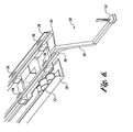
- FIGURE 6 is an isometric view of an example charge pulling device of the present invention;
- FIGURE 7A is a left side view of an example charge alignment device of the present invention;
- FIGURE 7B is a right side view of an example charge alignment device of the present invention; and
- FIGURE 7C is a front view of an example charge alignment device of the present invention.
-
- A machine and a method for forming composite materials are provided. By way of overview, the machine includes a frame and at least one forming beam attached to the frame, the at least one beam being arranged to align with a mandrel. The forming beam is pivotally segmented into at least two segments to conform to the shape of the mandrel or alternately is bendable to conform to the shape of the mandrel. The mandrel is receivable within the frame in alignment with the forming beam.
- An apparatus is also provided to position a composite charge over the mandrel and to position the mandrel within the frame. A further apparatus is provided to transport the mandrel and to urge the mandrel toward the forming beam.
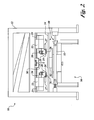
- FIGURE 1 illustrates an example
drape forming machine 10 of the present invention. In this embodiment, themachine 10 has aframe 12 with anopen side 14. Amandrel tool 90 removably fits within theopen side 14 of theframe 12. Composite parts such as beams and aircraft spars may be formed by themachine 10. Any suitable configuration of theframe 12 that allows themandrel tool 90 to removably fit within theframe 12 may be utilized. By way of example, in lieu of anopen side 14, themandrel tool 90 may suitably be fitted into theframe 12 through an end. - In the embodiment shown in FIGURE 1, the
frame 12 is approximately 48 feet long, and theopen side 14 allows access for a 43-footlong mandrel tool 90. The frame has a plurality of cross members 13 and legs 15. Theframe 12 rests on a floor that has been leveled to plus or minus .1 inch. It will be appreciated that any suitable uniform floor or support may be utilized for themachine 10 and themandrel tool 90. - FIGURE 2 is an end view of the
example machine 10 illustrated in FIGURE 1 and shows the details of the formingmachine 10 and themandrel tool 90. Movably attached to theframe 12 are formingbeams 20 utilized to form a composite material charge (not shown) over amandrel 92 attached to themandrel tool 90. Themandrel 92 is shaped to form the part being molded by themachine 10 when the composite charge is molded over themandrel 92. In this embodiment, the formingbeams 20 are held by forming beam supports 22 which ride onlinear bearings 23 attached to theframe 12. Thelinear bearings 23 allow the formingbeams 20 to be positioned against themandrel 92 for forming the composite charge over themandrel 92. The forming beams are positioned utilizing acme screwjacks and servo motors (not shown). The formingbeams 20 are suspended beneath theframe 12 of themachine 10 with the largelinear bearings 23 allowing lateral movement of the beams. The formingbeams 20 are segmented at the linear bearing 23 locations so that the forming beams can be bent or reconfigured to match tapers, doglegs, or large contours of the mandrel. It will be appreciated that flexibly positioning the segments of the formingbeams 20 allows themachine 10 to be configured to match the shape of many different mandrels, and thus to form a wide variety of composite parts, such as spars with tapers or joggles or curved beams. - Actuators are located at the pivot points (not shown) between the segments of the forming
beams 20. Although in this embodiment the actuators utilize acme screwjacks and servo motors (not shown), it will be appreciated that any suitable method of moving the forming beams and holding them in position relative to themandrel 92 may be utilized. For example, the formingbeams 20 are suitably actuated with pneumatic cylinders and set pins, hydraulic cylinders, electrical solenoids, linear motors, or scissor jacks. Formingbladders 28 are attached to the forming beams 20. In one embodiment, the formingbladders 28 suitably are inflated fire hose. It will be appreciated that any suitable flexible or pivoting material may be utilized to press the composite charge against themandrel 92. - Also attached to the forming
beams 20 are charge supports 26 which support the portions of the composite charge (not shown) which overhang themandrel 92 before they are pressed against the mandrel tool by the formingbladder 28. - The combination of the forming
beams 20,mandrel 92, and charge supports 26 implement the forming method of the above-identified related application, "Forming Method for Composites." It will also be appreciated that the machine of this invention and its component systems may be utilized in other forming methods. - The overhanging portions of the composite charge being urged against the
mandrel 92 are held in an "S" shape by the formingbladder 28 and thecharge support 26. This method minimizes the area and the amount of sliding where the composite charge laminate plys slide past one another as they are bent over themandrel 92. The method also assists in maintaining the laminate plys in tension as the forming process occurs. Supporting the unformed portions of the composite charge and progressively bending the composite charge to maintain an "S" shape minimizes out-of-plane fiber distortion. - In the embodiment shown in FIGURE 2, pinch bladders or plates are not utilized to hold the composite charge against the charge supports 26 during forming. Instead, the stiffness of the composite charge serves to hold the unformed portions of the composite charge against the charge supports 26, and thus substantially parallel with the upper surface of the
mandrel 92. Substantially parallel suitably includes an angle ranging from parallel with the upper surface of the mandrel 92 (0°) to a small angle up to 20°. Thus, in this embodiment, forming occurs without a pinch bladder or a pinch plate. - The
mandrel tool 90 with themandrel 92 is lifted up within theframe 12 between the formingbeams 20, thereby forming and molding the composite charge. In other embodiments, the formingbeams 20 are lowered over a fixedmandrel 92. It will be appreciated that any suitable method and orientation of moving the formingbeams 20 toward themandrel 92 will accomplish forming of the composite charge. - Attached to the charge supports 26 are
heater plates 24 that heat the composite charge, and soften it during the forming process. Theheater plates 24 are positioned on the charge supports 26. Theheater plates 24 can be extended or retracted toward themandrel 92 bypneumatic cylinders 27 controlled by a drape former controller (not shown). Given by way of non-limiting example, theheater plates 24 are suitably 480 volts alternating current (VAC) resistance heaters sandwiched between aluminum plates with a non-metallic bumper on the edge that will touch themandrel 92. However, other heat sources may be used as suitable for a particular application. By way of example, alternate heat sources may include hot air heat guns or infrared heaters. It will be appreciated that in some forming applications heater plates suitably would not be required to form the composite charge, and fixed or movable charge supports 26, withoutheater plates 24, would then support the composite charge during forming. - Movably attached to the
frame 12 is acharge pulling device 50 that pulls the composite charge (not shown) lengthwise along and over themandrel 92 and charge supports 26. Thecharge pulling device 50 thus loads the composite charge into themachine 10. Thecharge pulling device 50 is described in detail in connection with FIGURE 6 below. - The
machine 10 is equipped with abacking film remover 30. Thebacking film remover 30 removes a backing film (not shown) from the lower side of the composite charge (not shown) as it is drawn into themachine 10. Backing film (not shown) is utilized in some forming applications as a foundation for composite plies laid down by a computer numerically controlled (CNC) tape laying machine. The backing film remover includes abacking film roller 32 driven by a motor (not shown) which draws the backing film off the composite charge and onto thebacking film roller 32. The backing film is typically a plastic sheet and is broken from the composite charge as the composite charge is drawn across a breakingbar 34. The breaking bar is attached to theframe 12. In this embodiment, the motor driving thebacking film roller 32, through a slip clutch (not shown), operates at a slightly faster speed than thecharge pulling device 50 pulling the composite charge across the breaking bar. This keeps the backing film under tension to remove the film from the composite charge without ripping. Thebacking film remover 30 is located at the end of theframe 12 where the composite charge is loaded into themachine 10. Given by way of non-limiting example,backing film roller 32 is suitably a disposable or replaceable roller. This system peels and removes the backing film from the bottom of the composite charge as it is being loaded into themachine 10 by thecharge pulling device 50. A small radius corner of a square bar serves as the breakingbar 34 and breaks the bond between the backing film and the bottom of the composite charge. The film is then wound around the disposablebacking film roller 32. - During forming, the
mandrel tool 90 holding themandrel 92 is lifted vertically within theframe 12. This pushes themandrel 92 up between the formingbeams 20 and molds the composite charge over themandrel 92. Themandrel tool 90 is lifted by the tool transport and lifting device illustrated in FIGURES 5A and 5B. - The location and configurations of the forming
beams 20 and theheater plates 24 are controlled by a drape former controller (not shown) which configures the formingbeams 20 and theheater plates 24 in alignment with the mandrel in proper positions for forming the composite charge. The forming beams 20 match the shape of themandrel 92. Theheater plates 24 are positioned near or against themandrel 92. Themandrel 92 may have curves, joggles, bends or offsets that are matched by the forming beams and heater plates, and are set in position by the drape former controller. It will be appreciated that any suitable machine controller may be utilized to configure themachine 10 for a givenmandrel 92. Alternately, the formingbeams 20 andheater plates 24 may be positioned manually using manual measurements. - FIGURE 3A is a top view of an
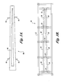
example mandrel tool 90. The mandrel tool is supported onlegs 91. In this embodiment, thelegs 91 are attached to themandrel tool 90 and remain attached to themandrel tool 90, even during forming. Thus, separate storage for the legs is not required, and themandrel tool 90 may be stored on itsown legs 91. Attached to themandrel tool 90 is themandrel 92 over which the composite materials or charges are formed. Themandrel 92 shown in FIGURE 3A is curved along its length. Themandrel 92 may have any shape or configuration that permits forming of the composite charges with acceptable levels of out-of-plane fiber distortion. - FIGURE 3B shows an exemplary embodiment of the
machine 10 of the present invention configured to match the contours of the mandrel 92 (FIGURE 3A). The two formingbeams 20 are each divided into four independently positionable segments 20A. The segments 20A are connected to each other by beam hinges 21. There are also beam hinges 21 at the ends of each formingbeam 20. The beam hinges 21 are attached to actuators (not shown). The actuators are linked to theframe 12 of themachine 10, allowing the segments 20A to be positioned to match the shape of themandrel 92. The example embodiment shown in FIGURE 3B shows the formingbeams 20 configured for themandrel 92 of FIGURE 3A. In this example configuration, the formingbeams 20 are more widely separated at one end than the other. The forming beams 20 also form convex and concave curves matching themandrel 92. It will be appreciated that the segments 20A may be positioned and held in any suitable manner to match anymandrel 92. For example, the segments 20A need not be hinged but may be pivoted. By way of further example, the segments 20A need be not be directly connected to each other, but may be suitably separately and independently positionable, allowing greater flexibility for forming composite charges over complex shaped mandrels. Similarly, the formingbeams 20 may be attached to theframe 12 in any suitable manner permitting the adjustment of their position relative to themandrel 92. It will be appreciated that aframe 12 may not be necessary where suitable means are provided for positioning and moving the segmented formingbeams 20 relative to themandrel 92. For example, hydraulic systems mounted to themandrel tool 90 or to a fixed surface could position and move the formingbeams 20 relative to themandrel 92 or could hold the formingbeams 20 in a fixed position as themandrel 92 is moved relative to the forming beams 20. - It will also be appreciated that a unitary flexible or bendable forming
beam 20 would form a shape conformable to themandrel 92 of Figure 3A, in the same manner as a segmented formingbeam 20. Similarly, one or more of the segments 20A may be flexible or bendable, providing versatility in conforming tocomplex mandrel 92 surfaces. By way of example, a bendable or flexible formingbeam 20 or segment 20A may be flexed and held in place by actuators (not shown) in the same manner as a segmented formingbeam 20. - In the example shown in FIGURE 3B, the forming
beams 20 each have 4 segments. In other embodiments a different number of segments may be used, such as a forming machine with 5 segment forming beams 20. - FIGURE 4A shows an embodiment of the
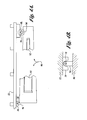
mandrel tool 90 positioning system and method of the present invention. Themandrel tool 90 is positioned against theframe 12. Themandrel tool 90 carries themandrel 92. Themandrel tool 90 has twosocket plates 94 which fit intoslots 16 attached to theframe 12. Thesocket plates 94 fit into theslots 16. Themandrel tool 90 is then lowered, with locating holes 95 in thesocket plates 94 sliding over chamfered locating pins 18 that position themandrel tool 90 in a fixed location relative to theframe 12. When thesocket plates 94 are inserted into theslot 16 and themandrel tool 90 is lowered over the locating pins 18, the center line of themandrel tool 90 is in alignment with the center line of theframe 12. It will be appreciated that theslots 16 andsocket plates 94 may be tapered or rounded to suitably mate with each other, positioning themandrel tool 90. It will also be appreciated the locatingpin 18 need not be cylindrical or chamfered, but may be any suitable shape to match with the corresponding locating hole 95. By way of example the locatingpin 18 may be tab shaped or pyramidal shaped. Alternately, by way of example, theslot 16 and the locatingpin 18 may be attached to themandrel tool 90, and thesocket plates 94 and locating holes 95 maybe attached to theframe 12, positioning themandrel tool 90 in a fixed location relative to theframe 12 in the same manner as the embodiment shown in FIGURE 4A. - FIGURE 4B is an enlarged top view of the
mandrel tool 90 with its attachedsocket plate 94. The socket plate is rounded and slides into the correspondingslot 16 attached to theframe 12. Themandrel tool 90 with its attachedsocket plate 94 is then lowered over the chamferedpin 18, thereby positioning themandrel tool 90. Positioning themandrel tool 90 is accomplished by lifting and moving themandrel tool 90 with a tool transport and lifting device, such as that shown in FIGURES 5A and 5B. Themandrel tool 90 is transported on air bearings to themachine 10 and positioned against theframe 12. Themandrel tool 90 is approximately located within theframe 12. Operators maneuver themandrel tool 90 so that the rounded ends of thesocket plates 94 line up with thetapered slots 16 attached to theframe 12 above the locating pins 18. In this example embodiment, tapered shape of theslot 16 helps guide thesocket plates 94 into position. Air bearings on the tool transport and lifting device are deflated and the tool transport lifting device settles to the floor with the location of themandrel tool 90 controlled by the locating holes 95 and the locating pins 18. Themandrel tool 90 is thus aligned with the center line of theframe 12. With the air bearings deflated, the horizontal location of themandrel tool 90 is fixed by friction on the floor. Themandrel tool 90, attached with themandrel 92, may then be lifted up into the forming beams of the drape forming machine (not shown) in proper position for molding the composite charge. The position of the mandrel during forming is held fixed by the weight of the tool transport lifting device (not shown) underneath themandrel tool 90 against the underlying floor. Themandrel tool 90 is thus located within plus or minus .1 inch relative to the formingmachine frame 12. This system permits the location of a plurality ofdifferent mandrel tools 90 in theframe assembly 12. Thesocket plates 94 thus accurately locate themandrel tool 90 within theframe 12. However, it will be appreciated that the precise position of the tool transport and lifting device (not shown) underneath themandrel tool 90 is not critical to the process of positioning themandrel tool 90 and lifting it up within theframe 12. - FIGURE 5A is a side view of a tool transport and lifting device (TTLD) 100 which carries and lifts the mandrel tool 90 (shown in phantom). The
TTLD 100 has aframe 105. Connected to theframe 105 areair bearings 110. Air bearings are commercially available items that are a low friction method to move theTTLD 100 and themandrel tool 90 across a floor. Air bearings allow operators to roughly position theTTLD 100 and themandrel tool 90 within the drape forming machine (not shown), without the need for additional power or assistance from the forming machine or any other equipment. It will be appreciated that any suitable method of moving theTTLD 100 may be utilized. For example, any acceptable form of high-load bearings or rollers could be used to move theTTLD 100. - Attached to the
frame 105 are screwjacks 120 which lift themandrel tool 90. In this embodiment, theTTLD 100 has four sets ofair bearings 110 and four sets of screwjacks andmotors 120. It will be appreciated that any suitable combination or number ofair bearings 110 and screwjacks andmotors 120 that lift themandrel tool 90 for transport and uniform lifting into the drape forming machine (not shown) may be used. - Given by way of non-limiting example, the screwjacks and motors each suitably include a pair of acme screws driven by a drive motor. It will be appreciated that any suitable lifting devices, such as hydraulic lifts or the like, may be utilized.
- FIGURE 5B is a top view of the
TTLD 100. Theframe 105 is configured to removably fit under themandrel tool 90. Theframe 105 is configured to fit around thelegs 91 of themandrel tool 90. This allows theTTLD 100 to be removably moved and slipped undermandrel tool 90, thereby allowing themandrel tool 90 to be stored while theTTLD 100 is utilized with other mandrel tools. Attached to theframe 105 are four sets of screwjacks andmotors 120 which lift themandrel tool 90. In this embodiment, theTTLD 100 lifts themandrel tool 90 without removing thelegs 91 from the tool. As a result, separate jacks for eachmandrel tool 90 and storage space for the legs is not required. - FIGURE 6 is an isometric view of the
charge pulling device 50 which pulls a composite charge (not shown) into the drape forming machine (not shown). Thecharge pulling device 50 is suspended fromlinear bearings 36 attached to the frame 12 (not shown). Thecharge pulling device 50 has a pullingarm 58 which holds acharge clamp 54. Thecharge clamp 54 is removably attached to thecharge pulling arm 58. In this embodiment, the charge pulling device has a locating feature (not shown) which is aligned with a target on the flat composite charge (not shown). A toggle-type clamp is then activated to accurately attach thecharge clamp 54 to the composite charge. Accurately locating thecharge clamp 54 on the composite charge permits the composite charge to be accurately positioned over the mandrel (not shown). - In one presently preferred embodiment, the composite charge is assembled by a CNC tape laying machine that lays plys in precise locations in the charge at alternating angles. After the
charge clamp 54 is attached to the composite charge (not shown), the composite charge is brought to the drape forming machine and thecharge clamp 54 is attached to the pullingarm 58. - The
charge pulling device 50 rides on thelinear bearings 36 attached to the drape former frame (not shown) with suitable charge pulling bearings or supports 56. Thelinear bearings 36 are located under the center line of the frame (not shown) of the drape forming machine. - The
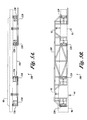
charge pulling device 50 is moved along thelinear bearings 36 by asuitable drive system 52. Thecharge pulling device 50 loads the composite charge by towing it down the length of the drape forming machine. Thedrive system 52 engages suitable drive tracks 38 that are attached to the drape former frame (not shown). When the composite charge (not shown) is pulled lengthwise by thecharge pulling device 50 into the drape forming machine, the composite charge slides on top of the top surface of the mandrel (not shown) and the heater plates (not shown). - FIGURE 7A shows a side view of the
charge pulling device 50 and the compositecharge alignment device 40. Thecharge pulling device 50 has acharge pulling arm 58 attached to acharge clamp 54. Thecharge pulling device 50 pulls the charge until it is stopped by thealignment device 40. Thealignment device 40 has aprojector boom 44 movably attached along the centerline of the drape forming machine frame (not shown). Theprojector boom 44 holds aprojector 41, such as without limitation a laser projector, used to position the projector boom relative to themandrel 92. Themandrel 92 has atooling hole 96. Theprojector 41 is precisely aligned with thetooling hole 96 by moving theprojector beam 44 along the centerline of the frame of the drape forming machine. This occurs when cross hairs or indicator projected by theprojector 41 line up with thetooling hole 96. This fixes theprojector boom 44 in a fixed position relative to themandrel 92. Theprojector boom 44 has aproximity switch 42 which senses the presence of the charge pullingdevice clamp 54 as thecharge pulling device 50 pulls the composite charge lengthwise into the drape forming machine. When theproximity switch 42 senses thecharge clamp 54, the drape former controller (not shown) stops thecharge pulling device 50 within a fixed distance. This positions the composite charge to within +/- 1/64 inch lengthwise on themandrel 92. The composite charge is pulled into the forming machine centered side to side on themandrel 92, in this embodiment to within +/- 1/8 inch. However, other tolerances may be used as desired for a particular application. It will also be appreciated that any suitable stopping method, including, by way of example, a hard stop that physically stops thecharge pulling device 50, may be used to stop thecharge pulling device 50. - Precise location of the composite charge with respect to the mandrel is often required for proper composite part fabrication. This is common for specialized parts such as aircraft spars. Precise location of the composite charge lengthwise within the drape forming machine permits ply drops, or the points where ply thicknesses change, to be positioned accurately with respect to the forming
mandrel 92. For aircraft spars, typically, ply drops are positioned lengthwise along the spar to within +/- .1 inch. This permits the composite parts to be precisely formed with the shapes, thicknesses and strengths for which they are designed. However, other tolerances may be used as desired for a particular application. - The method of aligning the composite charge in this embodiment thus includes projecting a cross-hair pattern or indicator on to the top surface of the
mandrel 92. An operator aligns theprojector 41 laser cross-hairs to the marker ortooling hole 96 on themandrel 92, and then locks theprojector boom 44 into place. Theboom 44, with itsproximity switch 42, is then properly located with respect to themandrel 92. Theproximity switch 42 is then used by the drape former controller (not shown) to stop the flat composite charge in the correct location with respect to themandrel tooling hole 96. Theprojector 41 is also used by the operator to verify that the flat composite charge is properly located after the charge is pulled into the drape forming machine. The operator visually verifies that the laser cross-hairs projected by theprojector 41 fall within the borders of a mark or a target on the flat composite charge, thereby verifying its proper alignment. In one embodiment, the mark on the composite charge is an inkjet target placed by a CNC laminate tape laying machine at the end of the composite charge lay up process. This provides verification that the composite charge is properly located laterally and longitudinally on themandrel 92 surface. - It will be appreciated that the
charge pulling device 50 andalignment device 40 properly position the composite charge lengthwise across themandrel 92 and ensure the proper side-to-side position of the composite charge at the end being pulled. At the opposite end of the drape forming machine (not shown), suitable lateral sliding guides linked to the heater plates center the composite charge side-to-side as the composite charge is being pulled into the drape forming machine by thecharge pulling device 50. It will be appreciated that any suitable method may be used to ensure that the end of the composite charge away from thecharge pulling device 50 is centered side-to-side over themandrel 92. - FIGURE 7B is a right side view of the
charge pulling device 50 and thealignment device 40. Thecharge pulling device 50 rides onlinear bearings 36 attached to the drape former frame (not shown) held on suitable charge pulling supports 56. The charge pulling device is driven by a charge pulling device drive system (not shown) utilizing pulling drive tracks 38 attached to the drape former frame (not shown). Thecharge pulling device 50 has a pullingarm 58, with adetachable charge clamp 54. Thecharge pulling device 50 is shown here in alignment with thealignment device 40. Thealignment device 40 has aprojector boom 44 which holds aprojector 41. Theprojector 41 allows indexing of theprojector boom 44 relative to thetooling hole 96 in themandrel 92. Themandrel 92 is attached to themandrel tool 90 which has been previously positioned by the tool transport and lifting device within the frame of the drape forming device (not shown). - It will be appreciated that alternate indexing systems other than a laser light projector may be utilized by the
alignment device 40. Any suitable indexing or measuring system that allows the position of the composite charge to be precisely located may be utilized by the present invention. - FIGURE 7C is a front view of the
charge pulling device 50 and thealignment device 40 positioned over themandrel 92. Thecharge pulling device 50, pullingsupports 56, and the supportinglinear bearings 36 attached to the drape former frame (not shown) are shown in cross-section. Thecharge pulling device 50 rides on thelinear bearings 36 thereby pulling the composite charge utilizing the pullingarm 58 attached to thecharge clamp 54. - The
alignment device 40 includes theprojector 41 and theproximity switch 42 attached to the projector boom 44 (not shown). Theprojector 41 is aligned with thetooling hole 96 in themandrel 92 thereby properly positioning thealignment device 40 Thealignment device 40 through the drape former controller (not shown) controls and stops thecharge pulling device 50 at the proper location over themandrel 92. Themandrel 92 is attached to themandrel tool 90. After the charge is positioned, theentire mandrel tool 90 is lifted up within the drape forming machine molding and forming the composite charge. - Forming a composite charge using the present invention is thus a multi-step process. In one present embodiment, the
mandrel tool 90 is brought to thedrape forming machine 10. The operator scans a barcode on themandrel tool 90 and a related work order, so that the drape forming machine can be configured properly. The drape former controller (not shown) compares part number information from the barcode scans, and then configures the formingbeams 20 to match the formingmandrel 92. - After the forming
beams 20 are configured properly, the tooltransport lifting device 100 has itsair bearings 110 inflated and the tool transport and liftingdevice 100 is removed from its storage position under thedrape forming machine 10. The tool transport and liftingdevice 100 is moved under themandrel tool 90. The tooltransport lifting device 100 is roughly positioned under themandrel tool 100, and theair bearings 110 are deflated. The acme screwjacks andmotors 120 on the tool transport and liftingdevice 100 are extended to lift themandrel tool 90 to a transportation elevation.Air bearings 110 on the tool transport and liftingdevice 100 are then reinflated and the operators move the mandrel tool to under thedrape forming machine 10. - The
mandrel tool 90 on the tool transport and liftingdevice 100 is then approximately located in the drapeformer frame 12. The operators maneuver themandrel tool 90 so that the rounded ends of thesocket plates 94 line up with theslots 16 over the chamfered locating pins 18. The tool transport and liftingdevice air bearings 110 are deflated and thepins 18 keep themandrel tool 90 from moving as the tool transport and liftingdevice 100 and themandrel tool 90 settle to the floor. This locates themandrel tool 90 to within approximately .1 inch within thedrape forming machine 10. The drape former controller then activates the tool transport and liftingdevice 100 to raise themandrel tool 92 up to a charge loading position. The charge loading position is suitably defined as the top of themandrel 92 just above the drapeformer heater plates 24. Theheater plates 24 on their charge supports 26 are then moved so that their bumpers rest against the side of themandrel 92. - The operators then prepare the
drape forming machine 10 so that the composite charge can be loaded. The operators first set and lock thealignment device 40 so that the cross-hairs projected by theprojector 41 is located on atooling hole 96 in themandrel 92. The operator next has the drape forming machine controller move thecharge pulling device 50 to the loading end of thedrape forming machine 10. Theremovable charge clamp 54 is removed from thecharge pulling device 50 and accurately attached to the flat composite charge. Thecharge clamp 54 is aligned to the composite charge by locating a feature on theclamp 54 with a target on the flat composite charge. The operator attaches theremovable charge clamp 54 to the charge pullingdevice arm 58. The operator then connects the protective backing film from the bottom of the flat composite charge to thebacking film roller 32 of thebacking film remover 30. Preparation for charge loading is then complete. - The operator then directs the drape forming machine controller to load the charge on the drape forming machine by activating the
charge pulling device 50 and thebacking film remover 30. The charge is towed lengthwise into thedrape forming machine 10 at a constant speed by thecharge pulling device 50. As the charge is pulled into thedrape forming machine 10, thebacking film remover 30 operates at a higher speed than thecharge pulling device 50 and with a slip clutch maintains tension on the backing film thereby removing the backing film from the composite charge. Just before the stopping point for thecharge pulling device 50, a target on the charge pulling device activates aproximity switch 42 on thealignment device 40. The drape forming machine controller then decelerates the composite charge and accurately stops the composite charge a precise distance later. The composite charge is then located directly in reference to themandrel 92. The operator then visually verifies the location of the composite charge by checking to see if cross-hairs projected by theprojector 41 fall on a target on the charge. Guides on the loading end of the formingmachine 10 keep the composite charge centered side-to-side over themandrel 92. The operator then removes thecharge clamp 54 from the composite charge and moves thecharge pulling device 50 out of the way of the forming beams 20. Thealignment device 40 is similarly moved out of the way. The operator then verifies that thebacking film remover 30 has removed all of the film from the bottom of the charge. - The operator then activates the drape former controller to implement the composite forming method described in the related application, "Forming Method for Composites." This process includes heating the charge with the
heater plates 24 and then using the tool transport and liftingdevice 100 to lift themandrel 92 up into thedrape forming machine 10 past the forming beams 20. Formingbladders 28 force the charge to conform to themandrel 92 contours as the unformed portions of the composite charge are held substantially parallel to the upper surface of themandrel 92 by theheater plates 24 and charge supports 26. Substantially parallel suitably may be an angle ranging from parallel with the upper surface of the mandrel 92 (i.e. 0°) to a small angle of up to 20°. This process molds the composite part in a manner that minimizes out-of-plane fiber distortion and buckles even when complex shapes with joggles, off-sets, and contours are formed. - The
heater plates 24 are turned off and the molded composite charge is allowed to cool. The formingbladders 28 then are deflated and theheater plates 24 and charge supports 26 are retracted. The forming beams 20 are retracted. The tool transport and liftingdevice 100 then lowers themandrel 92 andmandrel tool 90 along with the molded part back to an elevation where they may be transported. The operators then activate theair bearings 110 on the tool transport and liftingdevice 100 and move the mandrel with the molded composite charge to a vacuum bagging location where the molded charge is cured. The tool transport and liftingdevice 100 then lowers themandrel tool 90 to the floor, and the tool transport and liftingdevice 100 can be returned to thedrape forming machine 10 for further use. - While the preferred embodiment of the invention has been illustrated and described, as noted above, many changes can be made without departing from the spirit and scope of the invention. Accordingly, the scope of the invention is not limited by the disclosure of the preferred embodiment. Instead, the invention should be determined entirely by reference to the claims that follow.
Claims (48)
- An apparatus for forming composite materials, the apparatus comprising:a frame;at least one beam attached to the frame, the at least one beam being segmented into at least two segments, the at least two segments being arrangeable to form a shape for forming a composite charge; anda mandrel, having a first surface, the mandrel being receivable within the frame in alignment with the at least one beam, the mandrel being arranged to form the composite charge when the mandrel is received within the frame.
- An apparatus for forming composite materials, the apparatus comprising:a frame;at least one beam attached to the frame, the at least one beam being conformable into a shape for forming a composite charge; anda mandrel, having a first surface, the mandrel being receivable within the frame in alignment with the at least one beam, the mandrel being arranged to form the composite charge when the mandrel is received within the frame.
- The apparatus of Claim 1 or 2, wherein the at least two segments are independently positionable.
- The apparatus of Claim 1, 2 or 3, further comprising at least one positioning device that is attached to the frame and arranged to position the composite charge against the mandrel.
- The apparatus of Claim 4, wherein the positioning device includes a projector that is arranged to project an indicator onto the mandrel.
- The apparatus of any of Claims 1-5, further comprising at least one pulling device that is attached to the frame and arranged to pull the composite charge over the mandrel.
- The apparatus of any of Claims 1-6, wherein the at least one beam includes a forming device that is arranged to urge the composite charge against the mandrel.
- The apparatus of any of Claims 1-7, wherein the forming device includes a forming bladder.
- The apparatus of any of Claims 1-8, further comprising a moving device that is arranged to transport the mandrel toward the frame and urge the mandrel against the beam.
- The apparatus of any of Claims 1-9, wherein the at least one beam is flexibly conformable into a shape for forming a composite charge.
- An apparatus for forming composite materials, the apparatus comprising:a plurality of beam segments, each of the segments having first and second ends that are arranged end-to-end, the plurality of segments forming a segmented forming beam; andmeans for positioning the beam segments to conform to a mandrel.
- The apparatus of any of Claims 1-11, wherein the beam segments are pivotably attached end-to-end.
- The apparatus of any of Claims 1-12, wherein the beam segments are positioned with at least one actuator.
- The apparatus of Claim 13, wherein the at least one actuator includes a screwjack.
- The apparatus of any of Claims 1-14, wherein the beam segments are positioned pneumatically.
- The apparatus of any of Claims 1-15, further comprising at least one forming bladder attached to the forming beam, the forming bladder being arranged to urge a composite charge against the mandrel.
- The apparatus of any of Claims 1-16, further comprising at least one charge support that is arranged to support a portion of the composite charge that overhangs the mandrel substantially parallel with a first surface of the mandrel.
- The apparatus of any of Claims 1-17, further comprising at least one heater arranged to heat a portion of the composite charge that overhangs the mandrel.
- The apparatus of any of Claims 1-18, wherein the at least one heater is movably positioned to approach the mandrel.
- The apparatus of Claim 19, wherein the at least one heater is attached to the charge support.
- An apparatus for forming composite materials, the apparatus comprising:a frame;a mold attached to the frame;a mandrel receivable within the frame and the mold;a pulling device movably arranged to pull a composite charge to a predetermined location on the mandrel; andan indexing device that is arranged to stop the pulling device when the composite charge is at the predetermined location on the mandrel.
- The apparatus of any of Claims 1-21, wherein the indexing device is movably attached to the f rame.
- The apparatus of Claim 22, wherein the indexing device includes an indexing boom movably attached to the frame.
- The apparatus of any of Claims 1-23, wherein the mandrel defines a marker for positioning the indexing device.
- An apparatus for positioning a composite charge for forming composite materials, the apparatus comprising:a pulling device movably attached to a frame to pull a composite charge into a predetermined location on a mandrel;an indexing boom movably attached to the frame, an indexing device attached to the indexing boom, the indexing device being arranged to position the indexing boom relative to the mandrel; andmeans for stopping the pulling device at a location toward the indexing boom.
- The apparatus of any of Claims 1-25, wherein the stopping means includes a proximity switch arranged to activate when in proximity to the pulling device.
- The apparatus of any of Claims 1-26, wherein stopping means includes a hard stop arranged to stop the pulling device
- The apparatus of any of Claims 1-27, wherein the or an indexing device includes a projector arranged to project an indicator onto the mandrel.
- The apparatus of any of Claims 1-28, wherein the or an indexing device includes a projector arranged to project an indicator onto the composite charge.
- The apparatus of any of Claims 1-29, wherein the or a composite charge has a mark arranged to show the indicator for positioning of the composite charge.
- The apparatus of any of Claims 1-30, further comprising a clamp removably attachable to the pulling device and removably attachable to the composite charge.
- The apparatus of Claim 31, wherein the clamp defines a second marker and the composite charge defines a third marker, such that when the second marker is aligned with the third marker the clamp is positioned at a predetermined location on the composite charge.
- The apparatus of any of Claims 1-32, further comprising means for guiding the composite charge when the composite charge is pulled into the predetermined location.
- The apparatus of Claim 33, wherein the means for guiding the composite charge include at least one lateral guide.
- An apparatus for transporting and lifting a mandrel tool, the mandrel tool being arranged for forming composite materials, the apparatus comprising:a frame arranged to hold a mandrel for forming composite materials, the frame being movably receivable within a composite materials forming machine;a plurality of bearings attached to the frame, the plurality of bearings being arranged to move the frame across a surface and into the composite materials forming machine;a plurality of lifting devices arranged to lift the frame onto the bearings, the plurality of lifting jacks being further arranged to lift the mandrel tool within the composite materials forming machine; anda positioning device configured to position the mandrel at a predetermined position within the composite materials forming machine.
- The apparatus of any of Claims 1-35, wherein the means for positioning the mandrel include a plurality of plates arranged to fit within a plurality of slots attached to the frame.
- The apparatus of Claim 36, wherein the plates are further arranged to align with a plurality of pins that are attached to the frame.
- An apparatus for forming composite materials, the apparatus comprising:a frame;at least one beam attached to the frame, the at least one beam being segmented into at least two segments;a mandrel with a first surface, the mandrel receivable within the frame in alignment with the at least one beam, the mandrel being arranged to form a composite charge;a pulling device movably attached to a frame to pull a composite charge to a predetermined location on the mandrel;an indexing device arranged to stop the pulling device when the composite charge is at the predetermined location on the mandrel; anda transport device, arranged to transport the mandrel and lift the mandrel into the frame.
- An apparatus according to any combination of claims 1-38.
- A method for positioning a composite charge for forming composite materials, the method comprising:attaching to a composite charge a pulling device for pulling the composite charge;positioning an indexing boom at a first predetermined location in proximity to a mandrel;pulling the composite charge over the mandrel with the pulling device; andstopping the pulling device at a second predetermined position in proximity to the indexing boom.
- The method of Claim 40, further comprising verifying the pulling device is at the second predetermined location using a marker defined on the composite charge.
- The method of Claim 40 or 41, wherein attaching to a composite charge includes attaching a clamp at a third predetermined location on the composite charge.
- The method of Claim 40,41 or 42, wherein attaching the clamp includes defining a first marker on the composite charge and a second marker on the clamp.
- The method of any of Claims 40-43, wherein positioning the indexing boom includes projecting an indicator on the mandrel.
- The method of any of Claims 40-44, wherein positioning the indexing boom includes projecting an indicator on the composite charge.
- A method for positioning a mandrel tool for forming composite materials, comprising:providing a mandrel with a plurality of socket plates;providing a frame with a plurality of slots and locating pins that are arranged to mate with the socket plates;positioning the mandrel tool socket plates into the slots; andpositioning the mandrel tool socket plates onto the locating pins.
- A method for forming composite materials, the method comprising:attaching a mold to a frame;receiving a mandrel within the frame and the mold;pulling a composite charge to a predetermined location on the mandrel with a pulling device movably arranged to pull the composite charge;stopping the pulling device when the composite charge is at the predetermined location on the mandrel; andurging the composite charge against the mandrel.
- A composite material formed according to a method comprising:attaching a mold to a frame;receiving a mandrel within the frame and the mold; pulling a composite charge to a predetermined location on the mandrel with a pulling device movably arranged to pull the composite charge;stopping the pulling device when the composite charge is at the predetermined location on the mandrel; andurging the composite charge against the mandrel.
Applications Claiming Priority (2)
| Application Number | Priority Date | Filing Date | Title |
|---|---|---|---|
| US10/233,269 US7118370B2 (en) | 2002-08-30 | 2002-08-30 | Composite spar drape forming machine |
| US233269 | 2002-08-30 |
Publications (3)
| Publication Number | Publication Date |
|---|---|
| EP1393873A2 true EP1393873A2 (en) | 2004-03-03 |
| EP1393873A3 EP1393873A3 (en) | 2007-07-25 |
| EP1393873B1 EP1393873B1 (en) | 2011-06-22 |
Family
ID=31495413
Family Applications (1)
| Application Number | Title | Priority Date | Filing Date |
|---|---|---|---|
| EP03077556A Expired - Lifetime EP1393873B1 (en) | 2002-08-30 | 2003-08-14 | Composite spar drape forming machine and method |
Country Status (5)
| Country | Link |
|---|---|
| US (3) | US7118370B2 (en) |
| EP (1) | EP1393873B1 (en) |
| AT (1) | ATE513666T1 (en) |
| CA (2) | CA2436031C (en) |
| ES (1) | ES2365702T3 (en) |
Cited By (13)
| Publication number | Priority date | Publication date | Assignee | Title |
|---|---|---|---|---|
| EP2014448A2 (en) * | 2007-06-27 | 2009-01-14 | The Boeing Company | Method and apparatus for contouring composite pre-preg articles |
| WO2010047980A1 (en) * | 2008-10-25 | 2010-04-29 | The Boeing Company | Method and apparatus for forming highly contoured composite parts |
| WO2013056789A1 (en) * | 2011-10-20 | 2013-04-25 | Rehau Ag + Co | Method and device for building up a preform, formed part, computer program product and storage medium |
| US8465613B2 (en) | 2011-08-24 | 2013-06-18 | The Boeing Company | Method and apparatus for fabricating variable gauge, contoured composite stiffeners |
| US8601694B2 (en) | 2008-06-13 | 2013-12-10 | The Boeing Company | Method for forming and installing stringers |
| US8632330B2 (en) | 2006-01-31 | 2014-01-21 | The Boeing Company | Tools for manufacturing composite parts and methods for using such tools |
| US8702417B2 (en) | 2004-09-29 | 2014-04-22 | The Boeing Company | Apparatuses, systems, and methods for manufacturing composite parts |
| US8974212B2 (en) | 2004-07-26 | 2015-03-10 | The Boeing Company | Systems for manufacturing composite parts with female tools |
| US9254619B2 (en) | 2008-05-28 | 2016-02-09 | The Boeing Company | Method and apparatus for fabricating variable gauge, contoured composite stiffeners |
| US9387628B2 (en) | 2011-08-24 | 2016-07-12 | The Boeing Company | Method and apparatus for fabricating composite stringers |
| US10369740B2 (en) | 2015-07-09 | 2019-08-06 | The Boeing Company | Method of forming a contoured hat stiffener |
| EP4001127A1 (en) * | 2020-11-18 | 2022-05-25 | The Boeing Company | Continuous flow manufacturing system and apparatus and method for controlling a continuous flow manufacturing process |
| NL2027400B1 (en) * | 2021-01-26 | 2022-08-17 | Boeing Co | Continuous flow manufacturing system and apparatus and method for controlling a continuous flow manufacturing process |
Families Citing this family (45)
| Publication number | Priority date | Publication date | Assignee | Title |
|---|---|---|---|---|
| US7527759B2 (en) * | 2005-04-13 | 2009-05-05 | The Boeing Company | Method and apparatus for forming structural members |
| GB0613872D0 (en) * | 2006-07-12 | 2006-08-23 | Airbus Uk Ltd | Method of manufacturing composite part |
| US7588711B2 (en) * | 2006-11-21 | 2009-09-15 | The Boeing Company | Method for forming a composite support beam |
| US7861969B2 (en) * | 2007-05-24 | 2011-01-04 | The Boeing Company | Shaped composite stringers and methods of making |
| US7968169B2 (en) * | 2007-08-07 | 2011-06-28 | The Boeing Company | Compound contoured composite beams and fabrication methods |
| US7879276B2 (en) * | 2007-11-08 | 2011-02-01 | The Boeing Company | Foam stiffened hollow composite stringer |
| US8540921B2 (en) | 2008-11-25 | 2013-09-24 | The Boeing Company | Method of forming a reinforced foam-filled composite stringer |
| JP4735732B2 (en) * | 2009-03-25 | 2011-07-27 | 富士ゼロックス株式会社 | Cylindrical member manufacturing apparatus and cylindrical member manufacturing method |
| US8500066B2 (en) * | 2009-06-12 | 2013-08-06 | The Boeing Company | Method and apparatus for wireless aircraft communications and power system using fuselage stringers |
| US8570152B2 (en) * | 2009-07-23 | 2013-10-29 | The Boeing Company | Method and apparatus for wireless sensing with power harvesting of a wireless signal |
| US8617687B2 (en) * | 2009-08-03 | 2013-12-31 | The Boeing Company | Multi-functional aircraft structures |
| US8597015B2 (en) * | 2010-12-15 | 2013-12-03 | The Boeing Company | Airfoil manufacturing system |
| US9162396B2 (en) * | 2012-10-12 | 2015-10-20 | The Boeing Company | Method for forming fuselage stringers |
| US9409348B2 (en) | 2013-02-04 | 2016-08-09 | The Boeing Company | Fabrication of stiffened composite panels |
| US10150233B2 (en) | 2013-03-19 | 2018-12-11 | The Boeing Company | Method and apparatus for reducing ply wrinkling of composite laminates during forming |
| US9573301B2 (en) | 2013-03-19 | 2017-02-21 | The Boeing Company | Methodfor reducing ply wrinkling of composite laminates during forming |
| US9914268B2 (en) | 2014-06-04 | 2018-03-13 | The Boeing Company | Systems and methods for defining a surface contour of a layered charge of material |
| US10768128B2 (en) | 2014-07-22 | 2020-09-08 | The Boeing Company | Systems and methods of monitoring a thermal protection system |
| US10011080B2 (en) | 2014-09-29 | 2018-07-03 | The Boeing Company | Composite part forming system |
| US10518516B2 (en) | 2014-10-31 | 2019-12-31 | The Boeing Company | Method and system of forming a composite laminate |
| JP6543791B2 (en) * | 2015-06-04 | 2019-07-17 | 株式会社Subaru | Method of manufacturing resin molded body and press molding apparatus |
| DE102015211670A1 (en) * | 2015-06-24 | 2016-12-29 | Airbus Operations Gmbh | Method and device for mass production of components made of a fiber-reinforced composite material |
| US10456960B2 (en) * | 2015-07-24 | 2019-10-29 | The Boeing Company | Systems and methods for incrementally forming a composite part |
| US10195796B2 (en) | 2015-10-15 | 2019-02-05 | The Boeing Company | Systems and methods for drape forming a charge of composite material |
| US10688697B2 (en) | 2016-01-22 | 2020-06-23 | The Boeing Company | Apparatus and method of forming a composite structure |
| US10239251B2 (en) | 2016-01-22 | 2019-03-26 | The Boeing Company | Apparatus and method of forming a composite structure |
| US10328616B2 (en) | 2016-03-16 | 2019-06-25 | The Boeing Company | Charge shaping method |
| US11046034B2 (en) | 2016-04-18 | 2021-06-29 | Rohr, Inc. | Manufacturing a fiber-reinforced composite component using mandrels |
| US10882243B2 (en) | 2017-04-28 | 2021-01-05 | The Boeing Company | Adjustable height membrane for hot drape forming a part |
| US10525636B2 (en) | 2017-06-19 | 2020-01-07 | Rohr, Inc. | Process for forming a fiber-reinforced composite structure |
| US11668275B2 (en) * | 2017-11-21 | 2023-06-06 | General Electric Company | Methods for manufacturing an outer skin of a rotor blade |
| CA3126898A1 (en) | 2019-01-25 | 2020-07-30 | National Research Council Of Canada | Articulated forming caul for composite blank vacuum forming |
| US11565485B2 (en) | 2019-10-14 | 2023-01-31 | The Boeing Company | System, method, and apparatus for use in ply compaction in forming a composite structure |
| US11865825B2 (en) * | 2019-10-14 | 2024-01-09 | The Boeing Company | System, method, and apparatus for use in ply compaction in forming a composite structure |
| US11260607B2 (en) | 2020-02-11 | 2022-03-01 | The Boeing Company | Forming systems and methods for drape forming a composite charge |
| US11498288B2 (en) | 2020-02-11 | 2022-11-15 | The Boeing Company | Forming systems and methods for drape forming a composite charge |
| EP3967480A1 (en) | 2020-09-15 | 2022-03-16 | The Boeing Company | Systems and methods for forming composite members |
| US20220155764A1 (en) * | 2020-11-18 | 2022-05-19 | The Boeing Company | Continuous flow manufacturing system and apparatus and method for controlling a continuous flow manufacturing process |
| US11685128B2 (en) | 2020-12-07 | 2023-06-27 | The Boeing Company | System and method for fabricating a composite structure |
| US11964442B2 (en) | 2020-12-07 | 2024-04-23 | The Boeing Company | Forming apparatus, method, and system |
| US11654641B2 (en) | 2020-12-07 | 2023-05-23 | The Boeing Company | Composite ply placement system and method |
| US11826970B2 (en) | 2020-12-07 | 2023-11-28 | The Boeing Company | Forming apparatus, method, and system |
| US11931975B2 (en) | 2021-02-19 | 2024-03-19 | The Boeing Company | Forming systems and methods for forming an elongate charge of composite material |
| US11794376B2 (en) * | 2021-03-31 | 2023-10-24 | The Boeing Company | Application of gap fillers during layup of charges of composite material |
| US11897209B2 (en) | 2021-08-30 | 2024-02-13 | The Boeing Company | Composite forming apparatus, system and method |
Citations (1)
| Publication number | Priority date | Publication date | Assignee | Title |
|---|---|---|---|---|
| WO1996006725A1 (en) | 1994-08-31 | 1996-03-07 | The Boeing Company | Composite hot drape vacuum forming apparatus and method |
Family Cites Families (34)
| Publication number | Priority date | Publication date | Assignee | Title |
|---|---|---|---|---|
| US3025208A (en) * | 1957-08-01 | 1962-03-13 | Robert F Geiger | Apparatus for metal adhesive bonding |
| US3264392A (en) * | 1962-10-26 | 1966-08-02 | John F Taplin | Method of making rolling seal diaphragms |
| US3382530A (en) * | 1965-04-29 | 1968-05-14 | Dow Chemical Co | Apparatus for the preparation of shaped articles |
| US3799728A (en) * | 1972-05-18 | 1974-03-26 | Int Fabric Molders Inc | Mold closing device for fabric molding |
| US3956447A (en) * | 1975-06-16 | 1976-05-11 | The United States Of America As Represented By The Secretary Of The Army | Method of making deep drawn, laminated articles |
| US4035808A (en) * | 1976-04-30 | 1977-07-12 | Sanitary Scale Company | Label printer |
| FR2511656A1 (en) * | 1981-08-19 | 1983-02-25 | Aerospatiale | METHOD AND INSTALLATION FOR DRAPING PLIERS IN COMPOSITE MATERIALS |
| JPS5972728A (en) * | 1982-10-20 | 1984-04-24 | Canon Inc | Automatic alignment device |
| US4514246A (en) * | 1982-11-03 | 1985-04-30 | Gerber Garment Technology, Inc. | Method of cutting and labeling sheet material |
| US4475976A (en) * | 1983-12-23 | 1984-10-09 | The Boeing Company | Method and apparatus for forming composite material articles |
| CA1243177A (en) * | 1984-03-16 | 1988-10-18 | James B. Cattanach | Forming fibre-plastics composites |
| GB2168002B (en) * | 1984-12-06 | 1988-06-08 | Rolls Royce | Composite material manufacture |
| US5117348A (en) * | 1986-03-28 | 1992-05-26 | The Ingersoll Milling Machine Company | Method for alignment of a representative surface to an actual surface for a tape laying machine |
| US5076873A (en) * | 1988-11-04 | 1991-12-31 | The Boeing Company | Method for forming and curing an I-section workpiece |
| US4980013A (en) * | 1988-11-04 | 1990-12-25 | The Boeing Company | Apparatus for forming and curing an I-section workpiece |
| JPH072375B2 (en) * | 1989-03-22 | 1995-01-18 | 池田物産株式会社 | Interior material manufacturing method |
| US5484277A (en) * | 1989-12-26 | 1996-01-16 | Mcdonnell Douglas Corporation | Mandreless molding system |
| US5199595A (en) * | 1990-04-26 | 1993-04-06 | Alusuisse-Lonza Services Ltd. | Method of producing a cup-shaped, sterilisable container, as well as container |
| US5139604A (en) * | 1990-05-09 | 1992-08-18 | Mitchell Charles P | Controlled bladder wrap tool system |
| US5292475A (en) * | 1992-03-06 | 1994-03-08 | Northrop Corporation | Tooling and process for variability reduction of composite structures |
| FR2693146B1 (en) * | 1992-07-02 | 1994-08-19 | Snecma | Installation for the draping of multilayer structures in composite materials. |
| JP2585175B2 (en) * | 1993-01-14 | 1997-02-26 | 株式会社橘製作所 | Plate bending machine |
| US5657972A (en) * | 1994-12-22 | 1997-08-19 | Isi Norgren, Inc. | Clamp with inflatable bladder |
| US5648109A (en) * | 1995-05-03 | 1997-07-15 | Massachusetts Institute Of Technology | Apparatus for diaphragm forming |
| US5701651A (en) * | 1995-05-26 | 1997-12-30 | The Boeing Company | Composite stringer and skin panel assembly machine |
| US5882462A (en) * | 1996-02-02 | 1999-03-16 | Dow-United Technologies Composite Products | Method for fabricating a corrugated composite channel |
| JP3698517B2 (en) * | 1997-04-25 | 2005-09-21 | 富士重工業株式会社 | Composite material molding equipment |
| US5954917A (en) * | 1997-06-02 | 1999-09-21 | Boeing North American, Inc. | Automated material delivery system |
| US5902535A (en) * | 1997-07-30 | 1999-05-11 | Mcdonnell Douglas Corporation | Resin film infusion mold tooling and molding method |
| FR2791919B1 (en) * | 1999-04-12 | 2001-06-01 | Plastic Omnium Cie | METHOD FOR MAKING A REINFORCED PLASTIC PART BY OVERMOLDING A REINFORCING SHEET, DEVICE FOR IMPLEMENTING THIS PROCESS AND MANUFACTURING LINE COMPRISING THIS DEVICE |
| JP3400399B2 (en) * | 2000-01-11 | 2003-04-28 | 株式会社ジャムコ | Continuous molding equipment for F-shaped H-shaped members |
| US6682675B1 (en) * | 2000-03-15 | 2004-01-27 | Patent Holding Company | Method for co-molding a thermoplastic material with a thermoplastic sandwich material |
| JP2002248620A (en) | 2001-02-26 | 2002-09-03 | Toray Ind Inc | Base material for molding fiber-reinforced plastic and molding method of fiber-reinforced plastic |
| US6814916B2 (en) * | 2002-08-30 | 2004-11-09 | The Boeing Company | Forming method for composites |
-
2002
- 2002-08-30 US US10/233,269 patent/US7118370B2/en not_active Expired - Lifetime
-
2003
- 2003-07-28 CA CA002436031A patent/CA2436031C/en not_active Expired - Lifetime
- 2003-07-28 CA CA2663905A patent/CA2663905C/en not_active Expired - Lifetime
- 2003-08-14 EP EP03077556A patent/EP1393873B1/en not_active Expired - Lifetime
- 2003-08-14 AT AT03077556T patent/ATE513666T1/en not_active IP Right Cessation
- 2003-08-14 ES ES03077556T patent/ES2365702T3/en not_active Expired - Lifetime
-
2006
- 2006-08-10 US US11/463,784 patent/US7651650B2/en not_active Expired - Lifetime
-
2009
- 2009-11-03 US US12/611,599 patent/US8236222B2/en not_active Expired - Lifetime
Patent Citations (1)
| Publication number | Priority date | Publication date | Assignee | Title |
|---|---|---|---|---|
| WO1996006725A1 (en) | 1994-08-31 | 1996-03-07 | The Boeing Company | Composite hot drape vacuum forming apparatus and method |
Cited By (22)
| Publication number | Priority date | Publication date | Assignee | Title |
|---|---|---|---|---|
| US8974212B2 (en) | 2004-07-26 | 2015-03-10 | The Boeing Company | Systems for manufacturing composite parts with female tools |
| US8702417B2 (en) | 2004-09-29 | 2014-04-22 | The Boeing Company | Apparatuses, systems, and methods for manufacturing composite parts |
| US9561602B2 (en) | 2005-04-13 | 2017-02-07 | The Boeing Company | Forming highly contoured composite parts |
| US9162380B2 (en) | 2005-04-13 | 2015-10-20 | The Boeing Company | Forming highly contoured composite parts |
| US8632330B2 (en) | 2006-01-31 | 2014-01-21 | The Boeing Company | Tools for manufacturing composite parts and methods for using such tools |
| US9573355B2 (en) | 2007-06-27 | 2017-02-21 | The Boeing Company | Method and apparatus for contouring composite pre-preg articles |
| EP2014448A3 (en) * | 2007-06-27 | 2010-07-14 | The Boeing Company | Method and apparatus for contouring composite pre-preg articles |
| US8118959B2 (en) | 2007-06-27 | 2012-02-21 | The Boeing Company | Method and apparatus for contouring composite pre-preg articles |
| EP2014448A2 (en) * | 2007-06-27 | 2009-01-14 | The Boeing Company | Method and apparatus for contouring composite pre-preg articles |
| US9254619B2 (en) | 2008-05-28 | 2016-02-09 | The Boeing Company | Method and apparatus for fabricating variable gauge, contoured composite stiffeners |
| US9387627B2 (en) | 2008-06-13 | 2016-07-12 | The Boeing Company | Apparatus for forming and installing stringers |
| US8601694B2 (en) | 2008-06-13 | 2013-12-10 | The Boeing Company | Method for forming and installing stringers |
| EP2362826B2 (en) † | 2008-10-25 | 2016-09-07 | The Boeing Company | Method and apparatus for forming highly contoured composite parts |
| US8557165B2 (en) | 2008-10-25 | 2013-10-15 | The Boeing Company | Forming highly contoured composite parts |
| WO2010047980A1 (en) * | 2008-10-25 | 2010-04-29 | The Boeing Company | Method and apparatus for forming highly contoured composite parts |
| US9387628B2 (en) | 2011-08-24 | 2016-07-12 | The Boeing Company | Method and apparatus for fabricating composite stringers |
| US8465613B2 (en) | 2011-08-24 | 2013-06-18 | The Boeing Company | Method and apparatus for fabricating variable gauge, contoured composite stiffeners |
| WO2013056789A1 (en) * | 2011-10-20 | 2013-04-25 | Rehau Ag + Co | Method and device for building up a preform, formed part, computer program product and storage medium |
| US10369740B2 (en) | 2015-07-09 | 2019-08-06 | The Boeing Company | Method of forming a contoured hat stiffener |
| US11370159B2 (en) | 2015-07-09 | 2022-06-28 | The Boeing Company | Apparatus for forming a contoured hat stiffener |
| EP4001127A1 (en) * | 2020-11-18 | 2022-05-25 | The Boeing Company | Continuous flow manufacturing system and apparatus and method for controlling a continuous flow manufacturing process |
| NL2027400B1 (en) * | 2021-01-26 | 2022-08-17 | Boeing Co | Continuous flow manufacturing system and apparatus and method for controlling a continuous flow manufacturing process |
Also Published As
| Publication number | Publication date |
|---|---|
| EP1393873B1 (en) | 2011-06-22 |
| ES2365702T3 (en) | 2011-10-10 |
| CA2436031A1 (en) | 2004-02-29 |
| US7118370B2 (en) | 2006-10-10 |
| US7651650B2 (en) | 2010-01-26 |
| US20100043941A1 (en) | 2010-02-25 |
| CA2436031C (en) | 2009-11-03 |
| CA2663905A1 (en) | 2004-02-29 |
| US8236222B2 (en) | 2012-08-07 |
| EP1393873A3 (en) | 2007-07-25 |
| US20040041304A1 (en) | 2004-03-04 |
| US20060291991A1 (en) | 2006-12-28 |
| ATE513666T1 (en) | 2011-07-15 |
| CA2663905C (en) | 2011-07-12 |
Similar Documents
| Publication | Publication Date | Title |
|---|---|---|
| EP1393873B1 (en) | Composite spar drape forming machine and method | |
| EP3750694B1 (en) | Method and apparatus for fabricating contoured laminate structures | |
| US9162380B2 (en) | Forming highly contoured composite parts | |
| US8992715B2 (en) | System and method for the rapid, automated creation of advanced composite tailored blanks | |
| EP2015922B1 (en) | Apparatus and method for producing a large-area fibre-composite structural component | |
| EP3093130B1 (en) | System and method for manufacturing off-axis prepreg material | |
| EP3733387B1 (en) | Stiffener composite charge application system | |
| US20110240213A1 (en) | Method and device for laying and draping portions of a reinforcing fiber structure to produce a profiled preform | |
| US8683696B2 (en) | Positioning assembly for composite structure | |
| US8512497B2 (en) | Automated composite annular structure forming | |
| NL2023372B1 (en) | Preforming system and method | |
| CN110861321B (en) | Shaping of shaped elongated composite structures | |
| EP2839946A2 (en) | Transfer System and Method for Applying a Film Material to an Elongate Member | |
| EP4000887A1 (en) | Method and apparatus for placing multi-lane tows | |
| EP4000888B1 (en) | Continuously moving line for making composite laminate parts | |
| EP4008531A1 (en) | Forming apparatus, method, and system | |
| EP4001100A1 (en) | Method and system for assembling an aircraft wing including shims | |
| EP4011588A2 (en) | Placement of stringer sections preforms on a wing panel preform | |
| EP4000899A1 (en) | Method and system for carrying a wing panel of an aircraft | |
| EP4001098A1 (en) | Assembly line fabrication and assembly of aircraft wings | |
| EP4000900A1 (en) | Method and apparatus for installing indexing features into a composite part |
Legal Events
| Date | Code | Title | Description |
|---|---|---|---|
| PUAI | Public reference made under article 153(3) epc to a published international application that has entered the european phase |
Free format text: ORIGINAL CODE: 0009012 |
|
| AK | Designated contracting states |
Kind code of ref document: A2 Designated state(s): AT BE BG CH CY CZ DE DK EE ES FI FR GB GR HU IE IT LI LU MC NL PT RO SE SI SK TR |
|
| AX | Request for extension of the european patent |
Extension state: AL LT LV MK |
|
| RIC1 | Information provided on ipc code assigned before grant |
Ipc: B29C 33/30 20060101AFI20031220BHEP Ipc: B29C 70/54 20060101ALI20070419BHEP Ipc: B29C 70/34 20060101ALI20070419BHEP |
|
| PUAL | Search report despatched |
Free format text: ORIGINAL CODE: 0009013 |
|
| AK | Designated contracting states |
Kind code of ref document: A3 Designated state(s): AT BE BG CH CY CZ DE DK EE ES FI FR GB GR HU IE IT LI LU MC NL PT RO SE SI SK TR |
|
| AX | Request for extension of the european patent |
Extension state: AL LT LV MK |
|
| 17P | Request for examination filed |
Effective date: 20071122 |
|
| AKX | Designation fees paid |
Designated state(s): AT BE BG CH CY CZ DE DK EE ES FI FR GB GR HU IE IT LI LU MC NL PT RO SE SI SK TR |
|
| 17Q | First examination report despatched |
Effective date: 20080502 |
|
| RAP1 | Party data changed (applicant data changed or rights of an application transferred) |
Owner name: THE BOEING COMPANY |
|
| GRAP | Despatch of communication of intention to grant a patent |
Free format text: ORIGINAL CODE: EPIDOSNIGR1 |
|
| GRAS | Grant fee paid |
Free format text: ORIGINAL CODE: EPIDOSNIGR3 |
|
| GRAA | (expected) grant |
Free format text: ORIGINAL CODE: 0009210 |
|
| AK | Designated contracting states |
Kind code of ref document: B1 Designated state(s): AT BE BG CH CY CZ DE DK EE ES FI FR GB GR HU IE IT LI LU MC NL PT RO SE SI SK TR |
|
| REG | Reference to a national code |
Ref country code: GB Ref legal event code: FG4D |
|
| REG | Reference to a national code |
Ref country code: CH Ref legal event code: EP |
|
| REG | Reference to a national code |
Ref country code: IE Ref legal event code: FG4D |
|
| REG | Reference to a national code |
Ref country code: DE Ref legal event code: R096 Ref document number: 60337465 Country of ref document: DE Effective date: 20110811 |
|
| REG | Reference to a national code |
Ref country code: ES Ref legal event code: FG2A Ref document number: 2365702 Country of ref document: ES Kind code of ref document: T3 Effective date: 20111010 |
|
| REG | Reference to a national code |
Ref country code: NL Ref legal event code: VDEP Effective date: 20110622 |
|
| PG25 | Lapsed in a contracting state [announced via postgrant information from national office to epo] |
Ref country code: SE Free format text: LAPSE BECAUSE OF FAILURE TO SUBMIT A TRANSLATION OF THE DESCRIPTION OR TO PAY THE FEE WITHIN THE PRESCRIBED TIME-LIMIT Effective date: 20110622 |
|
| PG25 | Lapsed in a contracting state [announced via postgrant information from national office to epo] |
Ref country code: SI Free format text: LAPSE BECAUSE OF FAILURE TO SUBMIT A TRANSLATION OF THE DESCRIPTION OR TO PAY THE FEE WITHIN THE PRESCRIBED TIME-LIMIT Effective date: 20110622 Ref country code: AT Free format text: LAPSE BECAUSE OF FAILURE TO SUBMIT A TRANSLATION OF THE DESCRIPTION OR TO PAY THE FEE WITHIN THE PRESCRIBED TIME-LIMIT Effective date: 20110622 Ref country code: GR Free format text: LAPSE BECAUSE OF FAILURE TO SUBMIT A TRANSLATION OF THE DESCRIPTION OR TO PAY THE FEE WITHIN THE PRESCRIBED TIME-LIMIT Effective date: 20110923 Ref country code: CY Free format text: LAPSE BECAUSE OF FAILURE TO SUBMIT A TRANSLATION OF THE DESCRIPTION OR TO PAY THE FEE WITHIN THE PRESCRIBED TIME-LIMIT Effective date: 20110622 Ref country code: FI Free format text: LAPSE BECAUSE OF FAILURE TO SUBMIT A TRANSLATION OF THE DESCRIPTION OR TO PAY THE FEE WITHIN THE PRESCRIBED TIME-LIMIT Effective date: 20110622 |
|
| PG25 | Lapsed in a contracting state [announced via postgrant information from national office to epo] |
Ref country code: NL Free format text: LAPSE BECAUSE OF FAILURE TO SUBMIT A TRANSLATION OF THE DESCRIPTION OR TO PAY THE FEE WITHIN THE PRESCRIBED TIME-LIMIT Effective date: 20110622 Ref country code: BE Free format text: LAPSE BECAUSE OF FAILURE TO SUBMIT A TRANSLATION OF THE DESCRIPTION OR TO PAY THE FEE WITHIN THE PRESCRIBED TIME-LIMIT Effective date: 20110622 |
|
| PG25 | Lapsed in a contracting state [announced via postgrant information from national office to epo] |
Ref country code: CZ Free format text: LAPSE BECAUSE OF FAILURE TO SUBMIT A TRANSLATION OF THE DESCRIPTION OR TO PAY THE FEE WITHIN THE PRESCRIBED TIME-LIMIT Effective date: 20110622 Ref country code: EE Free format text: LAPSE BECAUSE OF FAILURE TO SUBMIT A TRANSLATION OF THE DESCRIPTION OR TO PAY THE FEE WITHIN THE PRESCRIBED TIME-LIMIT Effective date: 20110622 Ref country code: PT Free format text: LAPSE BECAUSE OF FAILURE TO SUBMIT A TRANSLATION OF THE DESCRIPTION OR TO PAY THE FEE WITHIN THE PRESCRIBED TIME-LIMIT Effective date: 20111024 |
|
| PG25 | Lapsed in a contracting state [announced via postgrant information from national office to epo] |
Ref country code: RO Free format text: LAPSE BECAUSE OF FAILURE TO SUBMIT A TRANSLATION OF THE DESCRIPTION OR TO PAY THE FEE WITHIN THE PRESCRIBED TIME-LIMIT Effective date: 20110622 Ref country code: SK Free format text: LAPSE BECAUSE OF FAILURE TO SUBMIT A TRANSLATION OF THE DESCRIPTION OR TO PAY THE FEE WITHIN THE PRESCRIBED TIME-LIMIT Effective date: 20110622 |
|
| PG25 | Lapsed in a contracting state [announced via postgrant information from national office to epo] |
Ref country code: MC Free format text: LAPSE BECAUSE OF NON-PAYMENT OF DUE FEES Effective date: 20110831 |
|
| REG | Reference to a national code |
Ref country code: CH Ref legal event code: PL |
|
| PLBE | No opposition filed within time limit |
Free format text: ORIGINAL CODE: 0009261 |
|
| STAA | Information on the status of an ep patent application or granted ep patent |
Free format text: STATUS: NO OPPOSITION FILED WITHIN TIME LIMIT |
|
| PG25 | Lapsed in a contracting state [announced via postgrant information from national office to epo] |
Ref country code: CH Free format text: LAPSE BECAUSE OF NON-PAYMENT OF DUE FEES Effective date: 20110831 Ref country code: LI Free format text: LAPSE BECAUSE OF NON-PAYMENT OF DUE FEES Effective date: 20110831 |
|
| REG | Reference to a national code |
Ref country code: IE Ref legal event code: MM4A |
|
| 26N | No opposition filed |
Effective date: 20120323 |
|
| PG25 | Lapsed in a contracting state [announced via postgrant information from national office to epo] |
Ref country code: DK Free format text: LAPSE BECAUSE OF FAILURE TO SUBMIT A TRANSLATION OF THE DESCRIPTION OR TO PAY THE FEE WITHIN THE PRESCRIBED TIME-LIMIT Effective date: 20110622 |
|
| REG | Reference to a national code |
Ref country code: DE Ref legal event code: R097 Ref document number: 60337465 Country of ref document: DE Effective date: 20120323 |
|
| PG25 | Lapsed in a contracting state [announced via postgrant information from national office to epo] |
Ref country code: IE Free format text: LAPSE BECAUSE OF NON-PAYMENT OF DUE FEES Effective date: 20110814 |
|
| PG25 | Lapsed in a contracting state [announced via postgrant information from national office to epo] |
Ref country code: LU Free format text: LAPSE BECAUSE OF NON-PAYMENT OF DUE FEES Effective date: 20110814 |
|
| PG25 | Lapsed in a contracting state [announced via postgrant information from national office to epo] |
Ref country code: BG Free format text: LAPSE BECAUSE OF FAILURE TO SUBMIT A TRANSLATION OF THE DESCRIPTION OR TO PAY THE FEE WITHIN THE PRESCRIBED TIME-LIMIT Effective date: 20110922 |
|
| PG25 | Lapsed in a contracting state [announced via postgrant information from national office to epo] |
Ref country code: TR Free format text: LAPSE BECAUSE OF FAILURE TO SUBMIT A TRANSLATION OF THE DESCRIPTION OR TO PAY THE FEE WITHIN THE PRESCRIBED TIME-LIMIT Effective date: 20110622 |
|
| PG25 | Lapsed in a contracting state [announced via postgrant information from national office to epo] |
Ref country code: HU Free format text: LAPSE BECAUSE OF FAILURE TO SUBMIT A TRANSLATION OF THE DESCRIPTION OR TO PAY THE FEE WITHIN THE PRESCRIBED TIME-LIMIT Effective date: 20110622 |
|
| REG | Reference to a national code |
Ref country code: FR Ref legal event code: PLFP Year of fee payment: 14 |
|
| REG | Reference to a national code |
Ref country code: FR Ref legal event code: PLFP Year of fee payment: 15 |
|
| REG | Reference to a national code |
Ref country code: FR Ref legal event code: PLFP Year of fee payment: 16 |
|
| PGFP | Annual fee paid to national office [announced via postgrant information from national office to epo] |
Ref country code: IT Payment date: 20220819 Year of fee payment: 20 Ref country code: GB Payment date: 20220829 Year of fee payment: 20 Ref country code: ES Payment date: 20220901 Year of fee payment: 20 Ref country code: DE Payment date: 20220829 Year of fee payment: 20 |
|
| PGFP | Annual fee paid to national office [announced via postgrant information from national office to epo] |
Ref country code: FR Payment date: 20220825 Year of fee payment: 20 |
|
| P01 | Opt-out of the competence of the unified patent court (upc) registered |
Effective date: 20230503 |
|
| REG | Reference to a national code |
Ref country code: DE Ref legal event code: R071 Ref document number: 60337465 Country of ref document: DE |
|
| REG | Reference to a national code |
Ref country code: ES Ref legal event code: FD2A Effective date: 20230825 |
|
| REG | Reference to a national code |
Ref country code: GB Ref legal event code: PE20 Expiry date: 20230813 |
|
| PG25 | Lapsed in a contracting state [announced via postgrant information from national office to epo] |
Ref country code: GB Free format text: LAPSE BECAUSE OF EXPIRATION OF PROTECTION Effective date: 20230813 Ref country code: ES Free format text: LAPSE BECAUSE OF EXPIRATION OF PROTECTION Effective date: 20230815 |