EP1394337A1 - Panel - Google Patents
Panel Download PDFInfo
- Publication number
- EP1394337A1 EP1394337A1 EP03019227A EP03019227A EP1394337A1 EP 1394337 A1 EP1394337 A1 EP 1394337A1 EP 03019227 A EP03019227 A EP 03019227A EP 03019227 A EP03019227 A EP 03019227A EP 1394337 A1 EP1394337 A1 EP 1394337A1
- Authority
- EP
- European Patent Office
- Prior art keywords
- groove
- panel
- edge
- base body
- panel according
- Prior art date
- Legal status (The legal status is an assumption and is not a legal conclusion. Google has not performed a legal analysis and makes no representation as to the accuracy of the status listed.)
- Granted
Links
Images


Classifications
-
- E—FIXED CONSTRUCTIONS
- E04—BUILDING
- E04F—FINISHING WORK ON BUILDINGS, e.g. STAIRS, FLOORS
- E04F15/00—Flooring
- E04F15/02—Flooring or floor layers composed of a number of similar elements
- E04F15/02005—Construction of joints, e.g. dividing strips
-
- E—FIXED CONSTRUCTIONS
- E04—BUILDING
- E04F—FINISHING WORK ON BUILDINGS, e.g. STAIRS, FLOORS
- E04F13/00—Coverings or linings, e.g. for walls or ceilings
- E04F13/07—Coverings or linings, e.g. for walls or ceilings composed of covering or lining elements; Sub-structures therefor; Fastening means therefor
- E04F13/08—Coverings or linings, e.g. for walls or ceilings composed of covering or lining elements; Sub-structures therefor; Fastening means therefor composed of a plurality of similar covering or lining elements
- E04F13/0801—Separate fastening elements
- E04F13/0803—Separate fastening elements with load-supporting elongated furring elements between wall and covering elements
- E04F13/081—Separate fastening elements with load-supporting elongated furring elements between wall and covering elements with additional fastening elements between furring elements and covering elements
- E04F13/0821—Separate fastening elements with load-supporting elongated furring elements between wall and covering elements with additional fastening elements between furring elements and covering elements the additional fastening elements located in-between two adjacent covering elements
- E04F13/0826—Separate fastening elements with load-supporting elongated furring elements between wall and covering elements with additional fastening elements between furring elements and covering elements the additional fastening elements located in-between two adjacent covering elements engaging side grooves running along the whole length of the covering elements
-
- E—FIXED CONSTRUCTIONS
- E04—BUILDING
- E04F—FINISHING WORK ON BUILDINGS, e.g. STAIRS, FLOORS
- E04F13/00—Coverings or linings, e.g. for walls or ceilings
- E04F13/07—Coverings or linings, e.g. for walls or ceilings composed of covering or lining elements; Sub-structures therefor; Fastening means therefor
- E04F13/08—Coverings or linings, e.g. for walls or ceilings composed of covering or lining elements; Sub-structures therefor; Fastening means therefor composed of a plurality of similar covering or lining elements
- E04F13/10—Coverings or linings, e.g. for walls or ceilings composed of covering or lining elements; Sub-structures therefor; Fastening means therefor composed of a plurality of similar covering or lining elements of wood or with an outer layer of wood
-
- E—FIXED CONSTRUCTIONS
- E04—BUILDING
- E04F—FINISHING WORK ON BUILDINGS, e.g. STAIRS, FLOORS
- E04F15/00—Flooring
- E04F15/02—Flooring or floor layers composed of a number of similar elements
- E04F15/04—Flooring or floor layers composed of a number of similar elements only of wood or with a top layer of wood, e.g. with wooden or metal connecting members
-
- E—FIXED CONSTRUCTIONS
- E04—BUILDING
- E04F—FINISHING WORK ON BUILDINGS, e.g. STAIRS, FLOORS
- E04F15/00—Flooring
- E04F15/02—Flooring or floor layers composed of a number of similar elements
- E04F15/02044—Separate elements for fastening to an underlayer
- E04F2015/0205—Separate elements for fastening to an underlayer with load-supporting elongated furring elements between the flooring elements and the underlayer
-
- E—FIXED CONSTRUCTIONS
- E04—BUILDING
- E04F—FINISHING WORK ON BUILDINGS, e.g. STAIRS, FLOORS
- E04F2201/00—Joining sheets or plates or panels
- E04F2201/05—Separate connectors or inserts, e.g. pegs, pins, keys or strips
-
- E—FIXED CONSTRUCTIONS
- E04—BUILDING
- E04F—FINISHING WORK ON BUILDINGS, e.g. STAIRS, FLOORS
- E04F2201/00—Joining sheets or plates or panels
- E04F2201/05—Separate connectors or inserts, e.g. pegs, pins, keys or strips
- E04F2201/0511—Strips or bars, e.g. nailing strips
Definitions
- the invention relates to a panel in particular for wall and / or Ceiling cladding, which with adjacent panels in groove and Spring engagement can be brought and on one long side and one Transverse side one by one visible side and one back groove limiting leg limited groove and to the opposite longitudinal and transverse sides one each has corresponding spring.
- the panels are on a as battens or the same trained support structure attached.
- the well-known Panels do not have panel fasteners Fastening the panels to the supporting structure. So far, as Fasteners used metal clips that one into a groove of the panel to be held insertable and one on the Have substructure attachable legs. The mentioned metal clips represent additional required parts that must be procured and installed.
- the strip-shaped, with through holes Edge areas advantageously form the panel's own Panel structure integrated fasteners that on the Substructure come to rest and simply through in one or more of the through holes receivable screws can be fixed on the substructure. Because the Edge areas containing through holes opposite the visible surface of the inner panel area are stepped, can the through holes as well as the heads of these received screws through the visible side Groove limiting leg of the adjacent panel be covered. This is the visible side Groove limiting leg is a little wider than that groove limiting leg on the back.
- the edge strips can expediently have a T-shaped cross section have and with the base body by tongue and groove be connected. This results in a particularly simple and inexpensive manufacture.
- this Measure can be in an assigned groove of the Main body engaging flange of the T-shaped edge strips with be provided with a continuous detent, which in one in the area groove provided in a side wall of the associated groove can be latched is. This advantageously enables a form-fitting, Connection between the base body and side strips without glue holds.
- the main field of application of the invention is panels for the production of wall and / or ceiling cladding.
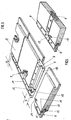
- a substructure indicated in FIGS. 1 and 7 is provided in the form of parallel slats 1 arranged at intervals corresponding to one another, to which the panels 2, as shown in FIG. 1, are fastened by screws 3 etc.
- the adjacent panels are brought circumferentially into tongue and groove engagement with adjacent panels.
- the panels 2 are provided with grooves 4 on two adjoining sides of their circumference and with springs 5 on the remaining two sides of their circumference. The arrangement of the grooves 4 and tongues 5 can be seen clearly from FIGS. 2 and 3.
- one longitudinal side and a transverse side adjoining it at right angles are provided with a groove 4 which is delimited by an upper, that is to say a groove-limiting leg 6 on the visible side and a lower, that is to say a groove-limiting leg 7 on the rear.
- a corresponding, outwardly projecting spring 5 is provided on the opposite longitudinal and transverse sides of the panel 2.
- the panels 2 each consist of one tabular base body 8, which on its springs 5 assigned longitudinal and transverse sides, each with an edge strip 9 is provided, from which the associated spring 5 protrudes outwards.
- the edge strips 9 form practically edge areas that the an inner panel area forming base body 8 on two Include pages.
- the visible surface of the edge strips 9 is, as is best Figure 5 is clearly visible, level with the visible side Surface of the associated spring 5. This is opposite the visible surface of the base body 8 by the thickness of the groove groove limb 6 on the visible side, so that as Figure 2 clearly shows, a step with the height s results.
- the rear surface of the edge strips 9 is, as can be seen from Figure 3 is flush with the back of the body 8. This way there is a continuous back of the panel 2, so that this also in the area of the sidebars Substructure 1 comes to rest, as can be seen from FIG. 1. This enables a reliable screwing of the panels 2 in Area of the marginal ridges 9.
- the groove limiter on the visible side 6, as FIG. 1 further shows, correspondingly wider than that rear groove limiting leg 7.
- the edge strips 9 to cover completely corresponds to the protrusion of the visible side Groove limiting leg 6 over the rear groove limiting leg 7 the distance between the base body 8 and the Neck cross-section of the spring 5 on the associated edge strip 9.
- the edge strips 9 can with their spring distant flank to the facing side surface of the base body 8, where a pin and / or glue connection is provided for connection can be.
- the edge strips 9 are through a tongue and groove connection connected to the base body 8.
- the edge strips 9 have a T-shaped cross section. This contains a middle one, with its underside on the Substructure 1 that can be brought into contact, designated in FIG. 1 Web 11, from which opposing flanges protrude, of which the flange directed away from the base body 8 is at the top already mentioned spring 5 running on the outside of the panel forms, while the base body 8 facing flange forms inner fastening spring 12, which in an associated groove 13th of the base body 8 engages, as can be seen from FIG. 1.
- the Base body 8 is accordingly in the area of all four circumferential sides grooved, being in the area of one long side and one on it then the transverse side of the springs 5 of the neighboring Panels assigned grooves 4 and in the area of the opposite Longitudinal and transverse sides of the springs 12 to be attached there Edge strips 9 associated grooves 13 are provided.
- the grooves 4 and 13 expediently have the same clear width and are equally spaced from the surface of the base body 8, so that the edge strips 9 have the aforementioned T-shape can.
- the flanges of the T-shaped springs 5 and 12, respectively Edge strips 9 have the same width that the depth of the Groove 13 or the groove 4 in the area of the rear groove limiting leg 7 corresponds.
- the supernatant of the visible side Groove limiting leg 6 over the rear groove limiting leg 7 suitably corresponds to the width of the middle Web 11 so that it can be completely covered.
- the spring 12 can by a glue connection in the associated Groove 13 be attached.
- a positive connection provided which is a sizing dispensable.
- the one engaging in the groove 13 Leg 12, as shown in Figures 1 and 4, with one over his Length continuous locking web 14 provided in an assigned Groove 15 of the facing side wall of the groove 13 can be snapped into place.
- the edge strip 9 assigned to a long side projects with its End area over the transverse side of the Base body 8 also.
- the protrusion corresponds to the width of the Web 11 plus the spring 5 of the edge strips projecting therefrom 9, as indicated in Figure 5 at b.
- the face of the Base body 8 overhanging edge strip 9 is accordingly flush with the outer flank 18 of the spring 5 which is transverse to it extending edge strip 9.
- the outward-pointing spring 5 of the Transverse edge strip 9 is coplanar with the after inside pointing spring 12 assigned to the long side Border 9, so that there is a continuous surface.
- the one with the spring 5 of the edge strip 9 assigned to the transverse side overlapping area of the spring 12 of the long side assigned edge bar 9 accordingly forms a Extension of the transverse spring 5 to the web 11 of the Longitudinal strip assigned to the long side 9.
- the basic body 8 facing side flank of the web 11 of the long side assigned edge bar 9 is accordingly on one of the width the spring 5 of the edge strip assigned to the transverse side corresponding width from the projection of the transverse side associated sidebar not covered. This uncovered
- the area is formed by a grid that is also indicated on the right in FIG. second support surface 19.
- the mutual support surfaces 17, 19 are mutually Support intervention, as indicated at 22.
- this support intervention can the newly connected panel 2a in the area of its end no longer in support surface normal Direction of the bandage already attached to the substructure move away, that is one in Figure 7 below by an arrow 23 indicated movement is excluded. It is therefore sufficient that support panel 2 to be connected at the other end, such as is indicated by the support arrow 24, while in one with a Batten 10 of the substructure 1 in congruence a screw is screwed in.
- This Panel 2a supports with one hand according to support arrow 24 and with the other hand operated a screwdriver.
- the base body 8 has accordingly one designed in a desired type of wood, e.g. veneered visible side.
- a desired type of wood e.g. veneered visible side.
- the edge strips 9 can easily and inexpensively as chipboard moldings be formed. But here would also be a solid wood version conceivable. Also training as an existing plastic Extrusion products would be conceivable.
Abstract
Description
Die Erfindung betrifft ein Paneel insbesondere für Wand- und/oder Deckenverkleidungen, das mit benachbarten Paneelen in Nut- und Federeingriff bringbar ist und an einer Längsseite und einer Querseite jeweils eine durch einen sichtseitigen und einen rückseitigen Nutbegrenzungsschenkel begrenzte Nut und an den jeweils gegenüberliegenden Längs- und Querseiten jeweils eine entsprechende Feder aufweist.The invention relates to a panel in particular for wall and / or Ceiling cladding, which with adjacent panels in groove and Spring engagement can be brought and on one long side and one Transverse side one by one visible side and one back groove limiting leg limited groove and to the opposite longitudinal and transverse sides one each has corresponding spring.
Bei der Erstellung von Paneelverbänden, wie Wand- und/oder Deckenverkleidungen, werden die Paneele auf einer als Lattung oder dergleichen ausgebildeten Tragkonstruktion befestigt. Die bekannten Paneele besitzen jedoch keine paneeleigenen Befestigungsmittel zur Befestigung der Paneele auf der Tragkonstruktion. Bisher werden als Befestigungsmittel Metallklammern verwendet, die einen in eine Nut des zu haltenden Paneels einführbaren Bügel und einen auf der Unterkonstruktion anbringbaren Schenkel aufweisen. Die genannten Metallklammern stellen zusätzlich benötigte Teile dar, die beschafft und montiert werden müssen. When creating panel dressings, such as wall and / or Ceiling panels, the panels are on a as battens or the same trained support structure attached. The well-known Panels, however, do not have panel fasteners Fastening the panels to the supporting structure. So far, as Fasteners used metal clips that one into a groove of the panel to be held insertable and one on the Have substructure attachable legs. The mentioned metal clips represent additional required parts that must be procured and installed.
Hiervon ausgehend ist es daher die Aufgabe der vorliegenden Erfindung, ein Paneel eingangs erwähnter Art mit einfachen und kostengünstigen Mitteln so zu verbessern, dass keine zusätzlichen Befestigungsmittel erforderlich sind und eine hohe Montagefreundlichkeit erreicht wird.Based on this, it is therefore the task of the present one Invention, a panel of the type mentioned with simple and to improve cost-effective means so that no additional Fasteners are required and ease of installation is achieved.
Diese Aufgabe wird erfindungsgemäß dadurch gelöst, dass die Federn von einem jeweils benachbarten, leistenförmigen Randbereich des Paneels abstehen, der gegenüber der sichtseitigen Oberfläche eines innerhalb des Randbereichs sich befindenden, inneren Paneelbereichs in Form einer Stufe abgesenkt ist und der rückseitig bündig mit dem inneren Paneelbereich ist und der mit wenigstens einer Bohrungsreihe mit mehreren, gleichmäßig über seine Länge verteilten Durchgangsbohrungen versehen ist.This object is achieved in that the Feathers from a neighboring, strip-shaped The edge area of the panel protrudes from the visible side Surface of an inside the edge area inner panel area is lowered in the form of a step and the is flush on the back with the inner panel area and with at least one row of holes with several, evenly over its length is distributed through holes.
Die mit Durchgangsbohrungen versehenen, leistenförmigen Randbereiche bilden in vorteilhafter Weise paneeleigene, in den Paneelaufbau integrierte Befestigungsmittel, die auf der Unterkonstruktion zur Auflage kommen und einfach durch in einer oder mehreren der Durchgangsbohrungen aufnehmbare Schrauben auf der Unterkonstruktion festlegbar sind. Da die die Durchgangsbohrungen enthaltenden Randbereiche gegenüber der sichtseitigen Oberfläche des inneren Paneelbereichs abgestuft sind, können die Durchgangsbohrungen sowie die Köpfe der in diesen aufgenommenen Schrauben durch den sichtseitigen Nutbegrenzungsschenkel des jeweils benachbarten Paneels überdeckt werden. Hierzu ist der sichtseitige Nutbegrenzungsschenkel zweckmäßig etwas breiter als der rückseitige Nutbegrenzungsschenkel. The strip-shaped, with through holes Edge areas advantageously form the panel's own Panel structure integrated fasteners that on the Substructure come to rest and simply through in one or more of the through holes receivable screws can be fixed on the substructure. Because the Edge areas containing through holes opposite the visible surface of the inner panel area are stepped, can the through holes as well as the heads of these received screws through the visible side Groove limiting leg of the adjacent panel be covered. This is the visible side Groove limiting leg is a little wider than that groove limiting leg on the back.
Vorteilhafte Ausgestaltungen und zweckmäßige Fortbildungen der übergeordneten Maßnahmen sind in den Unteransprüchen angegeben. So können die gegenüber der sichtseitigen Oberfläche des inneren Paneelbereichs abgesenkten Randbereiche jeweils durch eine an die zugeordnete Seite eines den inneren Paneelbereich bildenden Grundkörpers angesetzte Randleiste gebildet werden. Dies vereinfacht die Herstellung und ermöglicht in vorteilhafter Weise auch eine gezielte Verwendung unterschiedlicher Materialien bzw. unterschiedlicher Oberflächenbeschaffenheiten für den Grundkörper und für die Randleisten.Advantageous refinements and practical training of overriding measures are in the subclaims specified. So they can be compared to the visible surface edge areas of the inner panel area one to the associated side of the inner panel area forming basic body attached edge strip are formed. This simplifies production and advantageously allows also a targeted use of different materials or different surface textures for the base body and for the sidebars.
Zweckmäßig können die Randleisten einen T-förmigen Querschnitt aufweisen und mit dem Grundkörper durch Nut und Feder verbunden sein. Dies ergibt eine besonders einfache und kostengünstige Herstellung. In vorteilhafter Weiterbildung dieser Maßnahme kann dabei der in eine zugeordnete Nut des Grundkörpers eingreifende Flansch der T-förmigen Randleisten mit einem durchgehenden Raststeg versehen sein, der in eine im Bereich einer Seitenwand der zugeordneten Nut vorgesehene Rille einrastbar ist. Dies ermöglicht in vorteilhafter Weise eine formschlüssige, Verbindung zwischen Grundkörper und Randleisten, die ohne Leim hält.The edge strips can expediently have a T-shaped cross section have and with the base body by tongue and groove be connected. This results in a particularly simple and inexpensive manufacture. In an advantageous further development of this Measure can be in an assigned groove of the Main body engaging flange of the T-shaped edge strips with be provided with a continuous detent, which in one in the area groove provided in a side wall of the associated groove can be latched is. This advantageously enables a form-fitting, Connection between the base body and side strips without glue holds.
In weiterer Fortbildung der übergeordneten Maßnahmen können die vorzugsweise durch Randleisten gebildeten, leistenförmigen Randbereiche des Paneels mit ihren voneinander entfernten Enden jeweils am Nutgrund der quer hierzu verlaufenden Nut des inneren Paneelbereichs beginnen und mit ihren einander zugewandten Enden mit stumpfen Stoß aneinander anschließen, wobei der eine Randbereich die Stirnseite des anderen Randbereichs überdeckt. In further training of the overarching measures, the preferably formed by edge strips, strip-shaped Edge areas of the panel with their distant ends each at the bottom of the groove of the transverse groove of the inner Panel area begin and with their facing each other Connect the ends to each other with a butt joint, the one Edge area covers the end face of the other edge area.
Durch diese Maßnahme ergeben sich automatisch zwei Stützflächen, die bei aneinander anzuschließenden Paneelen in gegenseitigen Eingriff kommen und im Eingriffsbereich eine stützflächennormale gegenseitige Relativbewegung der beiden Paneele verhindern. Es ist daher in vorteilhafter Weise möglich, das neu anzuschließende, noch lose Paneel mit seiner Stützfläche zum Eingriff mit der zugeordneten Stützfläche des benachbarten, bereits auf der Unterkonstruktion befestigen Paneels zu bringen, wodurch das dem bereits befestigten Paneel zugewandte Ende des losen Paneels gehalten wird. Das andere Ende kann von einer Montageperson gehalten werden, die gleichzeitig eine Verschraubung durchführen kann. Es genügt daher in vorteilhafter Weise eine Montageperson, was eine hohe Montagefreundlichkeit und Wirtschaftlichkeit ergibt.This measure automatically results in two Support surfaces that in panels to be connected in mutual intervention and a normal support surface in the area of engagement mutual relative movement of the two panels prevent. It is therefore advantageously possible to do this new to be connected, still loose panel with its support surface for Engagement with the associated support surface of the neighboring one, already to attach panels to the substructure, bringing the end of the loose end facing the already attached panel Panels is held. The other end can be from one Assembly person can be held, the screwing at the same time can perform. It therefore suffices in an advantageous manner Assembly person what a high ease of assembly and Profitability results.
Weitere vorteilhafte Ausgestaltungen und zweckmäßige Fortbildungen der übergeordneten Maßnahmen sind in den restlichen Unteransprüchen angegeben und aus der nachstehenden Beispielsbeschreibung anhand der Zeichnung näher entnehmbar.Further advantageous configurations and expedient Further training of the overarching measures are in the remaining subclaims and from the following Example description can be taken from the drawing.
In der nachstehend beschriebenen Zeichnung zeigen:
- Figur 1
- einen Schnitt durch den Randbereich einander benachbarter, aneinander anzuschließender Paneele in auseinandergezogener Darstellung,
Figur 2- eine Draufsicht auf die Sichtseite eines erfindungsgemäßen Paneels in perspektivischer Darstellung,
Figur 3- eine Draufsicht auf die Rückseite eines erfindungsgemäßen Paneels in perspektivischer Darstellung,
Figur 4- eine Ansicht einer separaten Randleiste,
Figur 5- eine Draufsicht auf die Rückseite von zwei mit ihren Stützflächen in Eingriff bringbaren Paneelen in auseinandergezogener Darstellung,
Figur 6- die Paneele gemäß
Figur 5 in zusammengeschobenem Zustand und Figur 7- ein Montagebeispiel mit drei aufeinanderfolgenden Arbeitsgängen.
- Figure 1
- 3 shows a section through the edge region of mutually adjacent panels to be connected to one another in an exploded view,
- Figure 2
- 2 shows a top view of the visible side of a panel according to the invention in a perspective view,
- Figure 3
- 2 shows a top view of the back of a panel according to the invention in a perspective view,
- Figure 4
- a view of a separate sidebar,
- Figure 5
- 3 shows a plan view of the rear of two panels which can be brought into engagement with their supporting surfaces, in an exploded view,
- Figure 6
- the panels according to Figure 5 in the pushed together state
- Figure 7
- an assembly example with three successive operations.
Hauptanwendungsgebiet der Erfindung sind Paneele zur Herstellung
von Wand- und/oder Deckenverkleidungen. Hierzu wird eine in den
Figuren 1 und 7 angedeutete Unterkonstruktion in Form von in
einem Rastermaß entsprechenden Abständen angeordneten,
parallelen Latten 1 vorgesehen, an denen die Paneele 2, wie Figur 1
zeigt, durch Schrauben 3 etc. befestigt werden. Die einander
benachbarten Paneele werden dabei umlaufend in Nut- und
Federeingriff mit benachbarten Paneelen gebracht. Hierzu sind die
Paneele 2 an zwei aneinander anschließenden Seiten ihres Umfangs
mit Nuten 4 und an den restlichen zwei Seiten ihres Umfangs mit
Federn 5 versehen.
Die Anordnung der Nuten 4 und Federn 5 ist anschaulich aus den
Figuren 2 und 3 entnehmbar. Jeweils eine Längsseite und eine
rechtwinklig hieran anschließende Querseite ist mit einer Nut 4
versehen, die durch einen oberen, das heißt sichtseitigen
Nutbegrenzungsschenkel 6 und einen unteren, das heißt
rückseitigen Nutbegrenzungsschenkel 7 begrenzt wird. An den
jeweils gegenüberliegenden Längs- und Querseiten des Paneels 2 ist
jeweils eine entsprechende, nach außen auskragende Feder 5
vorgesehen.The main field of application of the invention is panels for the production of wall and / or ceiling cladding. For this purpose, a substructure indicated in FIGS. 1 and 7 is provided in the form of parallel slats 1 arranged at intervals corresponding to one another, to which the
The arrangement of the
Beim dargestellten Beispiel bestehen die Paneele 2 jeweils aus einem
tafelförmigen Grundkörper 8, der an seinen den Federn 5
zugeordneten Längs- und Querseiten mit jeweils einer Randleiste 9
versehen ist, von der die zugeordnete Feder 5 nach außen absteht.
Die Randleisten 9 bilden dabei praktisch Randbereiche, die den
einen inneren Paneelbereich bildenden Grundkörper 8 an zwei
Seiten umfassen.In the example shown, the
Die sichtseitige Oberfläche der Randleisten 9 ist, wie am besten aus
Figur 5 anschaulich erkennbar ist, niveaugleich mit der sichtseitigen
Oberfläche der zugehörigen Feder 5. Diese ist gegenüber der
sichtseitigen Oberfläche des Grundkörpers 8 um die Dicke des
sichtseitigen Nutbegrenzungsschenkels 6 abgesenkt, so dass sich,
wie Figur 2 anschaulich zeigt, eine Stufe mit der Höhe s ergibt. Die
rückseitige Fläche der Randleisten 9 ist, wie aus Figur 3 ersichtlich
ist, bündig mit der Rückseite des Grundkörpers 8. Auf diese Weise
ergibt sich eine durchgehende Rückseite des Paneels 2, so dass
dieses auch im Bereich der Randleisten satt auf der
Unterkonstruktion 1 zur Anlage kommt, wie aus Figur 1 hervorgeht.
Dies ermöglicht eine zuverlässige Verschraubung der Paneele 2 im
Bereich der Randleisten 9. The visible surface of the
Diese sind im Bereich zwischen ihrer Feder 5 und dem Grundkörper
8 mit durchgehenden Bohrungen 10 versehen, die in Form einer
über die ganze Randleistenlänge sich erstreckenden Bohrungsreihe
mit vergleichsweise kleinem, gegenseitigem Abstand angeordnet
sind. Zweckmäßig sind die Bohrungen so gleichmäßig über die
Länge des zugeordneten Randbereichs verteilt. Der gegenseitige
Abstand der Bohrungen 10 ist wesentlich kleiner als das der
Unterkonstruktion 1 zugrundeliegende Rastermaß so dass davon
auszugehen ist, däss über der Länge jedes Paneels 2 zumindest eine
Bohrung 10 zur Deckung mit einer Latte der Unterkonstruktion 1
kommt und zur Aufnahme einer Schraube 3 dienen kann. Die
Schrauben 3 können in Folge der satten Anlage der Randleisten 9
auf der Unterkonstruktion 1 bis auf Anschlag eingedreht werden,
ohne die Randleisten 9 auf Biegung zu beanspruchen.These are in the area between their
Im montierten Zustand werden die Bohrungen 10 und die
gegebenenfalls hierin aufgenommenen Schrauben 3 durch den
sichtseitigen Nutbegrenzungsschenkel 6 des jeweils benachbarten
Paneels 2 abgedeckt. Hierzu ist der sichtseitige Nutbegrenzungsschenkel
6, wie Figur 1 weiter zeigt, entsprechend breiter als der
rückseitige Nutbegrenzungsschenkel 7. Um die Randleisten 9
vollständig abzudecken entspricht der Überstand des sichtseitigen
Nutbegrenzungsschenkels 6 über den rückseitigen Nutbegrenzungsschenkel
7 dem Abstand zwischen dem Grundkörper 8 und dem
Ansatzquerschnitt der Feder 5 an der zugeordneten Randleiste 9.In the assembled state, the
Die Randleisten 9 können mit ihrer federfernen Flanke an die
zugewandte Seitenfläche des Grundkörpers 8 angesetzt sein, wobei
zur Verbindung eine Stift- und/oder Leimverbindung vorgesehen
sein kann. Im dargestellten Beispiel sind die Randleisten 9 durch
eine Nut- und Federverbindung mit dem Grundkörper 8 verbunden.
Hierzu besitzen die Randleisten 9 einen T-förmigen Querschnitt.
Dieser enthält einen mittleren, mit seiner Unterseite an der
Unterkonstruktion 1 zur Anlage bringbaren, in Figur 1 bezeichneten
Steg 11, von dem einander gegenüberliegende Flansche abstehen,
von denen der vom Grundkörper 8 weg gerichtete Flansch die oben
bereits erwähnte, an der Außenseite des Paneels verlaufende Feder 5
bildet, während der dem Grundkörper 8 zugewandte Flansch eine
innere Befestigungsfeder 12 bildet, die in eine zugeordnete Nut 13
des Grundkörpers 8 eingreift, wie aus Figur 1 hervorgeht. Der
Grundkörper 8 ist dementsprechend im Bereich aller vier Umfangsseiten
genutet, wobei im Bereich einer Längsseite und einer hieran
anschließenden Querseite die den Federn 5 der benachbarten
Paneele zugeordneten Nuten 4 und im Bereich der gegenüberliegenden
Längs- und Querseiten die den Federn 12 der dort anzusetzenden
Randleisten 9 zugeordneten Nuten 13 vorgesehen sind.The edge strips 9 can with their spring distant flank to the
facing side surface of the
Die Nuten 4 und 13 besitzen zweckmäßig dieselbe lichte Weite und
sind von der Oberfläche des Grundkörpers 8 gleich weit distanziert,
so dass die Randleisten 9 die schon erwähnte T-Form aufweisen
können. Die die Federn 5 bzw. 12 bildenden Flansche der T-förmigen
Randleisten 9 besitzen die gleiche Breite, die der Tiefe der
Nut 13 bzw. der Nut 4 im Bereich des rückwärtigen Nutbegrenzungsschenkels
7 entspricht. Der Überstand des sichtseitigen
Nutbegrenzungsschenkels 6 über den rückwärtigen Nutbegrenzungsschenkel
7 entspricht zweckmäßig der Breite des mittleren
Stegs 11, so dass dieser vollständig abgedeckt werden kann.The
Die Feder 12 kann durch eine Leimverbindung in der zugeordneten
Nut 13 befestigt sein. Im dargestellten Beispiel ist eine
formschlüssige Verbindung vorgesehen, die eine Leimung
entbehrlich macht. Hierzu ist der in die Nut 13 eingreifende
Schenkel 12, wie die Figuren 1 und 4 zeigen, mit einem über seine
Länge durchgehenden Raststeg 14 versehen der in eine zugeordnete
Rille 15 der zugewandten Seitenwand der Nut 13 einrastbar ist.The
Die voneinander abgewandten Enden der beiden Randleisten 9 eines
Paneels 2 beginnen, wie aus Figur 3 erkennbar ist, am Nutgrund der
quer hierzu verlaufenden Nuten 4. Hierdurch ergibt sich ein vom
Steg 11 der Randleiste 9 nicht abgedecktes Endstück des rückwärtigen
Begrenzungsschenkels 16 mit einer der Tiefe der quer
hierzu verlaufenden Nut 4 im Bereich des rückwärtigen Nutbegrenzungsschenkels
7 entsprechender Breite. Dieses nichtabgedeckte
Endstück bildet eine in Figur 5 links gerastert angedeutete
Stützfläche 17.The ends of the two
Die einander zugewandten Enden der Randleisten 9 schließen, wie
Figur 5 rechts erkennen lässt, mit stumpfem Stoß aneinander an.
Dabei ragt die einer Längsseite zugeordnete Randleiste 9 mit ihrem
Endbereich über die quer hierzu verlaufende Querseite des
Grundkörpers 8 hinaus. Der Überstand entspricht der Breite des
Stegs 11 zuzüglich der hiervon abstehenden Feder 5 der Randleisten
9, wie in Figur 5 bei b angedeutet ist. Die Stirnseite der den
Grundkörper 8 überragenden Randleiste 9 ist dementsprechend
bündig mit der äußeren Flanke 18 der Feder 5 der quer hierzu
verlaufenden Randleiste 9. Die nach außen weisende Feder 5 der der
Querseite zugeordneten Randleiste 9 ist koplanar mit der nach
innen weisenden Feder 12 der der Längssseite zugeordneten
Randleiste 9, so dass sich eine durchgehende Fläche ergibt. Der mit
der Feder 5 der der Querseite zugeordneten Randleiste 9 sich
überschneidende Bereich der Feder 12 der der Längsseite
zugeordneten Randleiste 9 bildet dementsprechend eine
Verlängerung der querseitigen Feder 5 bis zum Steg 11 der der
Längsseite zugeordneten Randleiste 9. Die dem Grundkörper 8
zugewandte Seitenflanke des Stegs 11 der der Längsseite
zugeordneten Randleiste 9 ist dementsprechend auf einer der Breite
der Feder 5 der der Querseite zugeordneten Randleiste
entsprechenden Breite von der Projektion der der Querseite
zugeordneten Randleiste nicht abgedeckt. Dieser nichtabgedeckte
Bereich bildet eine in Figur 5 rechts ebenfalls gerastert angedeutete,
zweite Stützfläche 19.The mutually facing ends of the
Wenn die den beiden Hälften der Figur 5 zugrundeliegenden
Paneele so zusammengeschoben werden, dass ihre einander
zugewandten, in Figur 5 noch voneinander beabstandeten
Querseiten aneinander anliegen, ergibt sich die Anordnung gemäß
Figur 6. Dabei greift die der Querseite des einen Paneels zugeordnete
Feder 5 einschließlich der oben beschriebenen Verlängerung in die
der zugewandten Querseite des anderen Paneels zugeordnete Nut 4
ein, wobei die Stützfläche 17 von der Stützfläche 19 übergriffen
wird, wie Figur 6 anschaulich zeigt. Auf diese Weise wird das an das
bereits befestigte Paneel angestellte, weitere Paneel mit seinem dem
genannten Stützflächeneingriff zugewandten Ende quer zur
Anstellrichtung formschlüssig fixiert, was die Montage vereinfacht,
wie nachstehend anhand der Figur 7 dargestellt werden wird.If the basis of the two halves of Figure 5
Panels are pushed together so that their are each other
facing, still spaced apart in Figure 5
If the transverse sides abut one another, the arrangement follows
Figure 6. The one assigned to the transverse side of the one panel engages
In Figur 7 sind mehrere Montageschritte dargestellt, die sich beim
Anfügen eines weiteren Paneels 2a an einen Verband von bereits auf
der Unterkonstruktion 1 befestigten Paneelen 2 ergeben. Das neu
anzufügende Paneel 2a wird zunächst, wie in Figur 7 oben durch
einen Pfeil 21 angedeutet ist, mit einer Längsseite an den Verband
angestellt, wobei seine längsseitige Nut 4 zum Eingriff mit der
zugewandten Feder 5 der hierzu parallelen Paneele 2 kommt.
Anschließend wird das neu anzuschließende Paneel 2a, wie in Figur
7 Mitte durch einen Pfeil 21 angedeutet ist, mit seiner Querseite an
die zugewandte Querseite des benachbarten Paneels 2 angestellt,
wobei die querseitige Nut 4 zum Eingriff mit der zugewandten Feder
5 des benachbarten Paneels 2 kommt. Dies ergibt die der Figur 7
unten zugrunde liegende Situation.In Figure 7, several assembly steps are shown, which are in the
Add another
Dabei sind die gegenseitigen Stützflächen 17, 19 in gegenseitigem
Stützeingriff, wie bei 22 angedeutet ist. Infolge dieses Stützeingriffs
kann sich das neu anzuschließende Paneel 2a im Bereich seines
stützeingriffseitigen Endes nicht mehr in stützflächennormaler
Richtung vom auf der Unterkonstruktion bereits befestigten Verband
wegbewegen, das heißt eine in Figur 7 unten durch einen Pfeil 23
angedeutete Bewegung ist ausgeschlossen. Es genügt daher, das
neu anzuschließende Paneel 2 am anderen Ende zu stützen, wie
durch den Stützpfeil 24 angedeutet ist, während in eine mit einer
Latte der Unterkonstruktion 1 in Deckung befindliche Bohrung 10
eine Schraube eingedreht wird. Dazu genügt eine Person, die das
Paneel 2a mit einer Hand gemäß Stützpfeil 24 stützt und mit der
anderen Hand einen Schrauber bedient.The mutual support surfaces 17, 19 are mutually
Support intervention, as indicated at 22. As a result of this support intervention
can the newly connected
Beim fertigverlegten Paneelverband sind nur die Sichtseiten der
Grundkörper 8 der Paneele 2 sichtbar. Der Grundkörper 8 besitzt
dementsprechend eine in einer gewünschten Holzart gestaltete, z.B.
furnierte Sichtseite. Selbstverständlich wäre es auch denkbar, den
Grundkörper 8 aus Massivholz herzustellen. Die Randleisten 9
können einfach und kostengünstig als Pressspanformlinge
ausgebildet werden. Aber auch hier wäre eine Massivholzausführung
denkbar. Auch eine Ausbildung als aus Kunststoff bestehende
Extrusionsprodukte wäre denkbar.When the panel assembly is installed, only the visible sides of the
Vorstehend ist zwar ein bevorzugtes Ausführungsbeispiel der
Erfindung näher erläutert, ohne dass jedoch hiermit eine
Beschränkung verbunden sein soll. So könnten anstelle von T-förmigen
Randleisten selbstverständlich auch im Querschnitt L-förmige
Randleisten Verwendung finden, die an die zugeordnete
Seitenflanke des Grundkörpers 8 angeleimt und/oder angestiftet
werden können. Ebenso wäre es denkbar, anstelle von ansetzbaren
Randleisten angeformte Randbereiche vorzusehen, was zu einer
einteiligen Paneelausführung führte.Above is a preferred embodiment of the
Invention explained in more detail, but without hereby a
Restriction should be connected. So instead of T-shaped ones
Edge strips of course also L-shaped in cross section
Sidebars are used to match the assigned
Side flank of the
Claims (10)
Applications Claiming Priority (2)
| Application Number | Priority Date | Filing Date | Title |
|---|---|---|---|
| DE10239146 | 2002-08-27 | ||
| DE10239146A DE10239146B4 (en) | 2002-08-27 | 2002-08-27 | paneling |
Publications (2)
| Publication Number | Publication Date |
|---|---|
| EP1394337A1 true EP1394337A1 (en) | 2004-03-03 |
| EP1394337B1 EP1394337B1 (en) | 2006-03-22 |
Family
ID=31197397
Family Applications (1)
| Application Number | Title | Priority Date | Filing Date |
|---|---|---|---|
| EP03019227A Expired - Lifetime EP1394337B1 (en) | 2002-08-27 | 2003-08-26 | Panel |
Country Status (3)
| Country | Link |
|---|---|
| EP (1) | EP1394337B1 (en) |
| AT (1) | ATE321176T1 (en) |
| DE (2) | DE10239146B4 (en) |
Cited By (6)
| Publication number | Priority date | Publication date | Assignee | Title |
|---|---|---|---|---|
| FR2880047A1 (en) * | 2004-12-24 | 2006-06-30 | Tecnopan Sa | Floor panel for e.g. capital structure, has male and female cooperating units disposed at level of opposite end sides for assembly with subsequent or preceding panel, and groove receiving cleat for aligning panel with adjacent panel |
| DE202009017071U1 (en) | 2009-12-17 | 2010-03-18 | Firstwood Gmbh | Profile board panel |
| FR2993590A1 (en) * | 2012-07-17 | 2014-01-24 | Sigebene | Method for edge to edge or face against face fixing of panels on e.g. floor of room, involves positioning assembly of fixing/securing and panel, so that element carries panel against wall at ad hoc location, and fixing element on wall |
| EP2664728A3 (en) * | 2012-05-14 | 2017-07-12 | Matclad Limited | Tile kit and method |
| CN107130760A (en) * | 2017-06-22 | 2017-09-05 | 嘉兴天美环保集成墙面有限公司 | A kind of assembled wall board being easily installed |
| EP3483354A1 (en) * | 2017-11-09 | 2019-05-15 | Hilmar Grünberger | Facade covering for covering a wall or building facade |
Families Citing this family (3)
| Publication number | Priority date | Publication date | Assignee | Title |
|---|---|---|---|---|
| DE102011001843A1 (en) | 2011-04-06 | 2012-10-11 | Guido Schulte | Cover for covering uneven surface of e.g. wall area, has fixing unit arranged in peripheral profiles of panels and including projection that is engaged with detent channel formed in region of profiles of one of panels |
| AT13835U1 (en) * | 2013-08-12 | 2014-09-15 | Sihga Handels Gmbh | Fixing of planks to a substructure |
| FR3011256B1 (en) * | 2013-09-27 | 2016-03-18 | Loisirs Equipements Soc | SURFACE COATING PANEL, ASSEMBLY COMPRISING AT LEAST TWO PANELS OF THE ABOVE TYPE AND SURFACE COATING OBTAINED |
Citations (7)
| Publication number | Priority date | Publication date | Assignee | Title |
|---|---|---|---|---|
| FR1569989A (en) * | 1968-04-23 | 1969-06-06 | ||
| DE7635021U1 (en) * | 1976-11-05 | 1978-02-02 | Mero-Werke Kg Dr.-Ing. Max Mengeringhausen, 8700 Wuerzburg | COMPONENT KIT FOR A MOUNTING FLOOR |
| DE3619046A1 (en) * | 1986-06-06 | 1987-12-10 | Gyproc Gmbh | Gypsum building board and pressure-distribution board produced from such building boards |
| FR2645219A1 (en) * | 1988-12-30 | 1990-10-05 | Tuduri Gerard | System for assembling panels |
| CA2305852A1 (en) * | 2000-04-14 | 2001-10-14 | Harry W. Eberle, Iii | Anchoring biscuit device |
| DE10044017C1 (en) * | 2000-09-06 | 2002-04-18 | Kronotec Ag | Device to connect floor panels has design whereby grooves in floor panels are bounded by upper and lower lip, with additional groove in upper lip of one side accommodating tongue in upper lip of opposite side |
| US6421970B1 (en) * | 1995-03-07 | 2002-07-23 | Perstorp Flooring Ab | Flooring panel or wall panel and use thereof |
Family Cites Families (2)
| Publication number | Priority date | Publication date | Assignee | Title |
|---|---|---|---|---|
| DE2447046A1 (en) * | 1974-10-02 | 1976-04-15 | Hilko Juerrens | INTERLOCKING WALL AND CEILING CLADDING PANEL - with one-piece tongue and groove respectively on each pair of opposite edges |
| DE7600832U1 (en) * | 1976-01-14 | 1976-05-06 | Gebr. Thome Kg, 7501 Forchheim | COMPONENT SET FOR THE CREATION OF FACTORY PRE-FABRICATED WALL PANELS |
-
2002
- 2002-08-27 DE DE10239146A patent/DE10239146B4/en not_active Expired - Fee Related
-
2003
- 2003-08-26 AT AT03019227T patent/ATE321176T1/en active
- 2003-08-26 DE DE50302718T patent/DE50302718D1/en not_active Expired - Lifetime
- 2003-08-26 EP EP03019227A patent/EP1394337B1/en not_active Expired - Lifetime
Patent Citations (7)
| Publication number | Priority date | Publication date | Assignee | Title |
|---|---|---|---|---|
| FR1569989A (en) * | 1968-04-23 | 1969-06-06 | ||
| DE7635021U1 (en) * | 1976-11-05 | 1978-02-02 | Mero-Werke Kg Dr.-Ing. Max Mengeringhausen, 8700 Wuerzburg | COMPONENT KIT FOR A MOUNTING FLOOR |
| DE3619046A1 (en) * | 1986-06-06 | 1987-12-10 | Gyproc Gmbh | Gypsum building board and pressure-distribution board produced from such building boards |
| FR2645219A1 (en) * | 1988-12-30 | 1990-10-05 | Tuduri Gerard | System for assembling panels |
| US6421970B1 (en) * | 1995-03-07 | 2002-07-23 | Perstorp Flooring Ab | Flooring panel or wall panel and use thereof |
| CA2305852A1 (en) * | 2000-04-14 | 2001-10-14 | Harry W. Eberle, Iii | Anchoring biscuit device |
| DE10044017C1 (en) * | 2000-09-06 | 2002-04-18 | Kronotec Ag | Device to connect floor panels has design whereby grooves in floor panels are bounded by upper and lower lip, with additional groove in upper lip of one side accommodating tongue in upper lip of opposite side |
Cited By (8)
| Publication number | Priority date | Publication date | Assignee | Title |
|---|---|---|---|---|
| FR2880047A1 (en) * | 2004-12-24 | 2006-06-30 | Tecnopan Sa | Floor panel for e.g. capital structure, has male and female cooperating units disposed at level of opposite end sides for assembly with subsequent or preceding panel, and groove receiving cleat for aligning panel with adjacent panel |
| DE202009017071U1 (en) | 2009-12-17 | 2010-03-18 | Firstwood Gmbh | Profile board panel |
| EP2336451A2 (en) | 2009-12-17 | 2011-06-22 | Firstwood GmbH | Profile board cladding |
| EP2664728A3 (en) * | 2012-05-14 | 2017-07-12 | Matclad Limited | Tile kit and method |
| FR2993590A1 (en) * | 2012-07-17 | 2014-01-24 | Sigebene | Method for edge to edge or face against face fixing of panels on e.g. floor of room, involves positioning assembly of fixing/securing and panel, so that element carries panel against wall at ad hoc location, and fixing element on wall |
| CN107130760A (en) * | 2017-06-22 | 2017-09-05 | 嘉兴天美环保集成墙面有限公司 | A kind of assembled wall board being easily installed |
| CN107130760B (en) * | 2017-06-22 | 2023-06-09 | 嘉兴天美环保集成墙面有限公司 | Combined wallboard convenient to install |
| EP3483354A1 (en) * | 2017-11-09 | 2019-05-15 | Hilmar Grünberger | Facade covering for covering a wall or building facade |
Also Published As
| Publication number | Publication date |
|---|---|
| EP1394337B1 (en) | 2006-03-22 |
| DE50302718D1 (en) | 2006-05-11 |
| DE10239146A1 (en) | 2004-03-25 |
| DE10239146B4 (en) | 2008-03-27 |
| ATE321176T1 (en) | 2006-04-15 |
Similar Documents
| Publication | Publication Date | Title |
|---|---|---|
| DE4215273C2 (en) | Covering for covering floor, wall and / or ceiling surfaces, in particular in the manner of a belt floor | |
| EP2208835B1 (en) | Panelling, in particular floor panelling | |
| EP2333195B1 (en) | Floor made of floor panels with separate connection components | |
| DE102007049792A1 (en) | connection | |
| DE19516530A1 (en) | Seal arrangement esp. for the lower edge of doors | |
| DE102009038750A1 (en) | Floor assembly has multiple rectangular plate-shaped floor assembly panels and mechanical blocking unit, where mechanical blocking unit is U-profile running in straight line along side surface of floor assembly panel | |
| DE102013106251A1 (en) | Mounting system for a floor covering | |
| EP1394337A1 (en) | Panel | |
| EP0802287A2 (en) | Height adjustable drainage grating | |
| EP2105065A1 (en) | Furniture body | |
| EP2320006B1 (en) | Floor panel with velcro elements | |
| EP3296486B1 (en) | Building cladding with a fitting set for the joining of elongated cover elements | |
| AT402834B (en) | ADJUSTABLE FIRST PANEL HOLDER FOR A ROOF CHAIR CONSTRUCTION | |
| DE3729378C2 (en) | ||
| DE10255204B3 (en) | Wall or ceiling panels for use in building have slotted edges engaging top parts of J-shaped fasteners and bottom parts of J-shapes engage in undercut grooves in wooden support laths | |
| DE202014004005U1 (en) | Fitting part and panel for use with such | |
| DE202006014727U1 (en) | Base end profile e.g. for heat insulation in buildings, has side having wall surface which can be cleaned, and bent side provided at obtuse angle to side on edge | |
| AT1025U1 (en) | COMPONENT AND WALL COVERING MADE THEREFOR | |
| DE202010007198U1 (en) | Floorboard laying system | |
| DE202007012444U1 (en) | shelving unit | |
| AT358258B (en) | FASTENING ELEMENT | |
| EP4039907A2 (en) | Floor arrangement, elongated floor profiles, end profiles and fascia profiles | |
| DE3016011C2 (en) | ||
| DE202022105475U1 (en) | Floor arrangement, elongated floor profile and end profile | |
| DE1658983C3 (en) | Sealing for expansion joints |
Legal Events
| Date | Code | Title | Description |
|---|---|---|---|
| PUAI | Public reference made under article 153(3) epc to a published international application that has entered the european phase |
Free format text: ORIGINAL CODE: 0009012 |
|
| AK | Designated contracting states |
Kind code of ref document: A1 Designated state(s): AT BE BG CH CY CZ DE DK EE ES FI FR GB GR HU IE IT LI LU MC NL PT RO SE SI SK TR |
|
| AX | Request for extension of the european patent |
Extension state: AL LT LV MK |
|
| 17P | Request for examination filed |
Effective date: 20040824 |
|
| AKX | Designation fees paid |
Designated state(s): AT BE BG CH CY CZ DE DK EE ES FI FR GB GR HU IE IT LI LU MC NL PT RO SE SI SK TR |
|
| 17Q | First examination report despatched |
Effective date: 20050124 |
|
| GRAP | Despatch of communication of intention to grant a patent |
Free format text: ORIGINAL CODE: EPIDOSNIGR1 |
|
| GRAS | Grant fee paid |
Free format text: ORIGINAL CODE: EPIDOSNIGR3 |
|
| GRAA | (expected) grant |
Free format text: ORIGINAL CODE: 0009210 |
|
| AK | Designated contracting states |
Kind code of ref document: B1 Designated state(s): AT BE BG CH CY CZ DE DK EE ES FI FR GB GR HU IE IT LI LU MC NL PT RO SE SI SK TR |
|
| PG25 | Lapsed in a contracting state [announced via postgrant information from national office to epo] |
Ref country code: RO Free format text: LAPSE BECAUSE OF FAILURE TO SUBMIT A TRANSLATION OF THE DESCRIPTION OR TO PAY THE FEE WITHIN THE PRESCRIBED TIME-LIMIT Effective date: 20060322 Ref country code: NL Free format text: LAPSE BECAUSE OF FAILURE TO SUBMIT A TRANSLATION OF THE DESCRIPTION OR TO PAY THE FEE WITHIN THE PRESCRIBED TIME-LIMIT Effective date: 20060322 Ref country code: GB Free format text: LAPSE BECAUSE OF FAILURE TO SUBMIT A TRANSLATION OF THE DESCRIPTION OR TO PAY THE FEE WITHIN THE PRESCRIBED TIME-LIMIT Effective date: 20060322 Ref country code: SI Free format text: LAPSE BECAUSE OF FAILURE TO SUBMIT A TRANSLATION OF THE DESCRIPTION OR TO PAY THE FEE WITHIN THE PRESCRIBED TIME-LIMIT Effective date: 20060322 Ref country code: SK Free format text: LAPSE BECAUSE OF FAILURE TO SUBMIT A TRANSLATION OF THE DESCRIPTION OR TO PAY THE FEE WITHIN THE PRESCRIBED TIME-LIMIT Effective date: 20060322 Ref country code: IE Free format text: LAPSE BECAUSE OF FAILURE TO SUBMIT A TRANSLATION OF THE DESCRIPTION OR TO PAY THE FEE WITHIN THE PRESCRIBED TIME-LIMIT Effective date: 20060322 |
|
| REG | Reference to a national code |
Ref country code: GB Ref legal event code: FG4D Free format text: NOT ENGLISH |
|
| REG | Reference to a national code |
Ref country code: CH Ref legal event code: EP |
|
| REG | Reference to a national code |
Ref country code: IE Ref legal event code: FG4D Free format text: LANGUAGE OF EP DOCUMENT: GERMAN |
|
| REF | Corresponds to: |
Ref document number: 50302718 Country of ref document: DE Date of ref document: 20060511 Kind code of ref document: P |
|
| PG25 | Lapsed in a contracting state [announced via postgrant information from national office to epo] |
Ref country code: SE Free format text: LAPSE BECAUSE OF FAILURE TO SUBMIT A TRANSLATION OF THE DESCRIPTION OR TO PAY THE FEE WITHIN THE PRESCRIBED TIME-LIMIT Effective date: 20060622 Ref country code: DK Free format text: LAPSE BECAUSE OF FAILURE TO SUBMIT A TRANSLATION OF THE DESCRIPTION OR TO PAY THE FEE WITHIN THE PRESCRIBED TIME-LIMIT Effective date: 20060622 Ref country code: BG Free format text: LAPSE BECAUSE OF FAILURE TO SUBMIT A TRANSLATION OF THE DESCRIPTION OR TO PAY THE FEE WITHIN THE PRESCRIBED TIME-LIMIT Effective date: 20060622 |
|
| PG25 | Lapsed in a contracting state [announced via postgrant information from national office to epo] |
Ref country code: ES Free format text: LAPSE BECAUSE OF FAILURE TO SUBMIT A TRANSLATION OF THE DESCRIPTION OR TO PAY THE FEE WITHIN THE PRESCRIBED TIME-LIMIT Effective date: 20060703 |
|
| PG25 | Lapsed in a contracting state [announced via postgrant information from national office to epo] |
Ref country code: PT Free format text: LAPSE BECAUSE OF FAILURE TO SUBMIT A TRANSLATION OF THE DESCRIPTION OR TO PAY THE FEE WITHIN THE PRESCRIBED TIME-LIMIT Effective date: 20060822 |
|
| PG25 | Lapsed in a contracting state [announced via postgrant information from national office to epo] |
Ref country code: MC Free format text: LAPSE BECAUSE OF NON-PAYMENT OF DUE FEES Effective date: 20060831 |
|
| NLV1 | Nl: lapsed or annulled due to failure to fulfill the requirements of art. 29p and 29m of the patents act | ||
| GBV | Gb: ep patent (uk) treated as always having been void in accordance with gb section 77(7)/1977 [no translation filed] |
Effective date: 20060322 |
|
| REG | Reference to a national code |
Ref country code: IE Ref legal event code: FD4D |
|
| PLBE | No opposition filed within time limit |
Free format text: ORIGINAL CODE: 0009261 |
|
| STAA | Information on the status of an ep patent application or granted ep patent |
Free format text: STATUS: NO OPPOSITION FILED WITHIN TIME LIMIT |
|
| 26N | No opposition filed |
Effective date: 20061227 |
|
| EN | Fr: translation not filed | ||
| PG25 | Lapsed in a contracting state [announced via postgrant information from national office to epo] |
Ref country code: GR Free format text: LAPSE BECAUSE OF FAILURE TO SUBMIT A TRANSLATION OF THE DESCRIPTION OR TO PAY THE FEE WITHIN THE PRESCRIBED TIME-LIMIT Effective date: 20060623 Ref country code: FR Free format text: LAPSE BECAUSE OF FAILURE TO SUBMIT A TRANSLATION OF THE DESCRIPTION OR TO PAY THE FEE WITHIN THE PRESCRIBED TIME-LIMIT Effective date: 20070309 |
|
| PG25 | Lapsed in a contracting state [announced via postgrant information from national office to epo] |
Ref country code: FI Free format text: LAPSE BECAUSE OF FAILURE TO SUBMIT A TRANSLATION OF THE DESCRIPTION OR TO PAY THE FEE WITHIN THE PRESCRIBED TIME-LIMIT Effective date: 20060322 Ref country code: EE Free format text: LAPSE BECAUSE OF FAILURE TO SUBMIT A TRANSLATION OF THE DESCRIPTION OR TO PAY THE FEE WITHIN THE PRESCRIBED TIME-LIMIT Effective date: 20060322 |
|
| PG25 | Lapsed in a contracting state [announced via postgrant information from national office to epo] |
Ref country code: TR Free format text: LAPSE BECAUSE OF FAILURE TO SUBMIT A TRANSLATION OF THE DESCRIPTION OR TO PAY THE FEE WITHIN THE PRESCRIBED TIME-LIMIT Effective date: 20060322 Ref country code: HU Free format text: LAPSE BECAUSE OF FAILURE TO SUBMIT A TRANSLATION OF THE DESCRIPTION OR TO PAY THE FEE WITHIN THE PRESCRIBED TIME-LIMIT Effective date: 20060923 Ref country code: LU Free format text: LAPSE BECAUSE OF NON-PAYMENT OF DUE FEES Effective date: 20060826 |
|
| PG25 | Lapsed in a contracting state [announced via postgrant information from national office to epo] |
Ref country code: FR Free format text: LAPSE BECAUSE OF FAILURE TO SUBMIT A TRANSLATION OF THE DESCRIPTION OR TO PAY THE FEE WITHIN THE PRESCRIBED TIME-LIMIT Effective date: 20060322 Ref country code: CY Free format text: LAPSE BECAUSE OF FAILURE TO SUBMIT A TRANSLATION OF THE DESCRIPTION OR TO PAY THE FEE WITHIN THE PRESCRIBED TIME-LIMIT Effective date: 20060322 |
|
| PGFP | Annual fee paid to national office [announced via postgrant information from national office to epo] |
Ref country code: CZ Payment date: 20080811 Year of fee payment: 6 |
|
| PG25 | Lapsed in a contracting state [announced via postgrant information from national office to epo] |
Ref country code: IT Free format text: LAPSE BECAUSE OF NON-PAYMENT OF DUE FEES Effective date: 20070826 |
|
| PG25 | Lapsed in a contracting state [announced via postgrant information from national office to epo] |
Ref country code: CZ Free format text: LAPSE BECAUSE OF NON-PAYMENT OF DUE FEES Effective date: 20090826 |
|
| PGFP | Annual fee paid to national office [announced via postgrant information from national office to epo] |
Ref country code: IT Payment date: 20070828 Year of fee payment: 5 |
|
| PGRI | Patent reinstated in contracting state [announced from national office to epo] |
Ref country code: IT Effective date: 20110616 |
|
| PGFP | Annual fee paid to national office [announced via postgrant information from national office to epo] |
Ref country code: BE Payment date: 20110822 Year of fee payment: 9 |
|
| BERE | Be: lapsed |
Owner name: *FENDT HERMANN Effective date: 20120831 |
|
| PG25 | Lapsed in a contracting state [announced via postgrant information from national office to epo] |
Ref country code: BE Free format text: LAPSE BECAUSE OF NON-PAYMENT OF DUE FEES Effective date: 20120831 |
|
| PGFP | Annual fee paid to national office [announced via postgrant information from national office to epo] |
Ref country code: CH Payment date: 20130826 Year of fee payment: 11 Ref country code: AT Payment date: 20130821 Year of fee payment: 11 |
|
| PGRI | Patent reinstated in contracting state [announced from national office to epo] |
Ref country code: IT Effective date: 20110616 |
|
| REG | Reference to a national code |
Ref country code: CH Ref legal event code: PL |
|
| REG | Reference to a national code |
Ref country code: AT Ref legal event code: MM01 Ref document number: 321176 Country of ref document: AT Kind code of ref document: T Effective date: 20140826 |
|
| PG25 | Lapsed in a contracting state [announced via postgrant information from national office to epo] |
Ref country code: LI Free format text: LAPSE BECAUSE OF NON-PAYMENT OF DUE FEES Effective date: 20140831 Ref country code: CH Free format text: LAPSE BECAUSE OF NON-PAYMENT OF DUE FEES Effective date: 20140831 |
|
| PG25 | Lapsed in a contracting state [announced via postgrant information from national office to epo] |
Ref country code: AT Free format text: LAPSE BECAUSE OF NON-PAYMENT OF DUE FEES Effective date: 20140826 |
|
| PGFP | Annual fee paid to national office [announced via postgrant information from national office to epo] |
Ref country code: DE Payment date: 20150831 Year of fee payment: 13 |
|
| REG | Reference to a national code |
Ref country code: DE Ref legal event code: R119 Ref document number: 50302718 Country of ref document: DE |
|
| PG25 | Lapsed in a contracting state [announced via postgrant information from national office to epo] |
Ref country code: DE Free format text: LAPSE BECAUSE OF NON-PAYMENT OF DUE FEES Effective date: 20170301 |