EP1398272A1 - Machine for depositing and fixing flat objects on container batches - Google Patents
Machine for depositing and fixing flat objects on container batches Download PDFInfo
- Publication number
- EP1398272A1 EP1398272A1 EP03366007A EP03366007A EP1398272A1 EP 1398272 A1 EP1398272 A1 EP 1398272A1 EP 03366007 A EP03366007 A EP 03366007A EP 03366007 A EP03366007 A EP 03366007A EP 1398272 A1 EP1398272 A1 EP 1398272A1
- Authority
- EP
- European Patent Office
- Prior art keywords
- batch
- conveyor
- machine according
- shims
- depositing
- Prior art date
- Legal status (The legal status is an assumption and is not a legal conclusion. Google has not performed a legal analysis and makes no representation as to the accuracy of the status listed.)
- Withdrawn
Links
Images

Classifications
-
- B—PERFORMING OPERATIONS; TRANSPORTING
- B65—CONVEYING; PACKING; STORING; HANDLING THIN OR FILAMENTARY MATERIAL
- B65B—MACHINES, APPARATUS OR DEVICES FOR, OR METHODS OF, PACKAGING ARTICLES OR MATERIALS; UNPACKING
- B65B61/00—Auxiliary devices, not otherwise provided for, for operating on sheets, blanks, webs, binding material, containers or packages
- B65B61/20—Auxiliary devices, not otherwise provided for, for operating on sheets, blanks, webs, binding material, containers or packages for adding cards, coupons or other inserts to package contents
- B65B61/22—Auxiliary devices, not otherwise provided for, for operating on sheets, blanks, webs, binding material, containers or packages for adding cards, coupons or other inserts to package contents for placing protecting sheets, plugs, or wads over contents, e.g. cotton-wool in bottles of pills
Definitions
- the present invention relates to a machine for removing and fixing flat objects such as wedges and / or cardboard boxes on lots of containers, for example in the form of a brick.
- a machine according to the invention has for the purpose of depositing and fixing, for example by adhesive tape, on the part top of a batch of four six or eight bricks of milk or drink, a wedge rectangular for example in polystyrene, before covering the lot with a film shrink.
- This arrangement not known from the prior art has the function of give good stability to pallets made up of such lots and facilitate gripping lots.
- the invention consists of a machine for the packaging industry of the type comprising at least one conveyor for continuously driving batches of containers for example from a filling filling device to the entry of a film-forming machine, characterized in that it comprises a set of means suitable for place and fix at high speed a flat object on the upper part of each lot of containers scrolling on the conveyor.
- a batch (1) after filling corking is conventionally transported by a gravity conveyor, then brought to the deposit station (4) by two conveyors to strip (5, 6) (see Figure 3).
- the first conveyor, or cadence conveyor (5) has the function of spacing the lots (1) which are already arranged one behind the other and perpendicularly when moving, plugs (7) on top.
- a barrier cell for stop the cadating conveyor (5) at each passage of a batch, thus creating a predetermined spacing between two successive batches.
- the second conveyor rotates the batch of 90 ° bricks on a pivot (11) located at the entrance of the turning conveyor and the batch is now located longitudinally along the axis of movement of the conveyor turner.
- the plugs (7) protrude from the upper face of the batch and arranged along two projecting lateral lines between which a rectangular wedge as explained below.
- Lateral guide means (12) are provided on the reversing conveyor (6) batches so as to align them under the hold to be deposited and under a conveyor distribution of shims (10) of the depositing station (4) while a shim is present at the outlet of said distributor (10).
- Said wedge is deposited on the fly on the batch of bricks at the outlet of the conveyor hold; this authorizes the lifting of an arm (8) making it possible to bring the lot (1) with adhesive tape placed in a tape store (13).
- the lot-hold assembly then drives the end of the adhesive tape.
- the hold stores (14,15) are parallelepipedic boxes openable, for example by means of a removable side door (21), the presence is for example detected by a coded magnet or a safety contact to key.
- the stores are preferably designed to receive shims of three different lengths, which can be adapted to batches of three different lengths, depending on the number of bricks assembled (4 or 6 or 8).
- the shims are preferably presented assembled in packages called “Bundles” (22), and composed of several columns of stacked wedges, allowing autonomy of predetermined duration.
- the loading table (16) driven by a jack rises to its upper position.
- the machine therefore has a jack which raises the loading table to its high position, after the lower magazine has been loaded with a bundle (22), and the door was closed.
- a mobile push plate (18) will push transversely the bundle towards the upper magazine (15 ').
- the loading table can come down and be loaded again.
- a longitudinal push plate (18) will push the bundle up a cell.
- a lateral pusher (20) transfers a column of shims into the distributor shims (10).
- a blocking cylinder (23) is in the extended position during the column transfer and in the retracted position during unstacking.
- a vertical pressure cylinder (24) descends to press the row of shims and ensure unstacking of shims without jamming or blocking of the shims.
- a wedge pusher cylinder (25) pushes a wedge from the column unstacked to deposit it in an articulated tunnel (17).
- the blocking cylinder (23) starts in the low position and an air jet pushes the wedge longitudinally inside the articulated tunnel, then under the wedge distribution conveyor (10).
- the hold conveyor (10) drives the wedge that comes out of the tunnel and lays it at the same speed as the return conveyor (5) which takes the batch in order to deposit it on the face superior of said lot.
- the wedge is placed on top of a batch of bricks and between the two lines of plugs then immediately fixed by the adhesive tape on the batch of bricks.
- the hold conveyor (10) drives the following hold, and the articulated tunnel is loaded again, etc ...
- a second mode of operation of the machine is now described according to the invention namely the removal of a cardboard on a lot and serving as a handle.
- the bilge depositing station (4) is not used in this operating mode.
- the timing conveyor (5) retains its function of spacing the lots which are already arranged one behind the other and perpendicular to the movement.
- the second conveyor (6) advances the batch of bricks through the wedge removal assembly without rotating it 90 °.
- a carton (28) from a carton store (30) is distributed using a cardboard cylinder (29) and on said adhesive tape.
- the assembly (batch of bricks) advances and drives the adhesive tape;
- the ribbon is cut (7). Then, in front of another cell, an aspiring arm (11) rises by sucking the ribbon with the cardboard to form a space about 10 mm between the cardboard and the top of the batch so that the end customer can pass the fingers to carry the lot.
- the batch of bricks is then turned 90 ° at the exit of the turning conveyor (5) by a pivot not shown.
- the invention sees its application to the continuous removal and fixing and to high rate, stackable flat objects, i.e. plate-shaped contour not necessarily rectangular, on a flat surface of a batch of containers such as for example, a batch of bricks, bottles or the like, this before their passage in a filming machine.
- the machine according to the invention is capable of operating at high rates in use in filling systems for bottles, bricks or other lines bottling.
- Said machine is in no case a palletizer, but a depositing machine holds and handles on a container with maximum dimensions approximate are as follows: length 384 mm - height 250 mm - width 130 mm.
- the particularity being the pace since the removal and fixing are carried out at the same rate as that of the scrolling of the batches which example can reach 1,500 deposits per hour.
Abstract
Description
La présente invention concerne une machine pour la dépose et la fixation d'objets plats par exemple des cales et/ou des cartonnettes sur des lots de contenants, par exemple en forme de brique.The present invention relates to a machine for removing and fixing flat objects such as wedges and / or cardboard boxes on lots of containers, for example in the form of a brick.
Selon une application préférée et non limitative, une machine selon l'invention a pour but de déposer et de fixer, par exemple par un ruban adhésif, sur la partie supérieure d'un lot de quatre six ou huit briques de lait ou de boisson, une cale rectangulaire par exemple en polystyrène, avant le recouvrement du lot par un film thermorétractable. Cet aménagement non connu de l'art antérieur a pour fonction de conférer une bonne stabilité aux palettes constituées de tels lots et de faciliter la préhension des lots.According to a preferred and nonlimiting application, a machine according to the invention has for the purpose of depositing and fixing, for example by adhesive tape, on the part top of a batch of four six or eight bricks of milk or drink, a wedge rectangular for example in polystyrene, before covering the lot with a film shrink. This arrangement not known from the prior art has the function of give good stability to pallets made up of such lots and facilitate gripping lots.
L'invention consiste en une machine pour l'industrie de l'emballage du type comportant au moins un convoyeur pour conduire en continu des lots de contenants par exemple depuis un dispositif de remplissage bouchage jusqu'à l'entrée d'une filmeuse, caractérisé en ce qu'elle comporte un ensemble de moyens aptes à déposer et fixer à cadence élevée un objet plat sur la partie supérieure de chaque lot de contenants défilant sur le convoyeur.The invention consists of a machine for the packaging industry of the type comprising at least one conveyor for continuously driving batches of containers for example from a filling filling device to the entry of a film-forming machine, characterized in that it comprises a set of means suitable for place and fix at high speed a flat object on the upper part of each lot of containers scrolling on the conveyor.
Plus particulièrement elle comporte successivement entre une entrée des lots et une sortie desdits lots :
- un convoyeur cadenseur à bande pour espacer les lots et les acheminer selon une première direction d'acheminement,
- un convoyeur retourneur à bande succédant au convoyeur cadenseur et comportant un pivot effaçable apte à faire pivoter chaque lot de 90°, lorsqu'il n'est pas effacé, par rapport à la direction d'acheminement,
- des moyens de guidage latéral des lots de manière à aligner ceux-ci sous l'objet plat à déposer, l'objet plat étant distribué un à un par un distributeur ou un poste de dépose à la même vitesse que le lot,
- un bras permettant de mettre en contact le lot avec l'extrémité d'un ruban adhésif tandis que le lot continue son cheminement,
- des moyens pour couper le ruban adhésif et pour l'appliquer sur le lot.
- a belt conveyor belt to space the lots and route them in a first direction of transportation,
- a belt return conveyor succeeding the cadence conveyor and comprising an erasable pivot able to rotate each batch by 90 °, when it is not erased, relative to the direction of transport,
- means for lateral guidance of the batches so as to align them under the flat object to be deposited, the flat object being distributed one by one by a distributor or a deposition station at the same speed as the batch,
- an arm making it possible to bring the batch into contact with the end of an adhesive tape while the batch continues its journey,
- means for cutting the adhesive tape and applying it to the lot.
Selon une première variante le poste de dépose est un poste de dépose de cales comportant essentiellement :
- un magasin inférieur de cales,
- un magasin supérieur de cales,
- une table de chargement,
- un ensemble de moyens de dépilage et de poussée d'une cale,
- un tunnel de réception,
- un ensemble de dépose des cales sur un lot de briques comportant un convoyeur de cales des moyens de guidage et de centrage du lot de briques prévus sur le convoyeur de la machine,
- une armoire de puissance et une armoire de commande.
- a lower hold store,
- a top hold store,
- a loading table,
- a set of means for unstacking and pushing a hold,
- a reception tunnel,
- an assembly for depositing the shims on a batch of bricks comprising a shim conveyor means for guiding and centering the batch of bricks provided on the conveyor of the machine,
- a power cabinet and a control cabinet.
Selon une deuxième variante elle comporte en outre un poste de dépose de cartonnettes comportant :
- des moyens pour arrêter le poste de déposer des cales et effacer le pivot du convoyeur retourneur de manière que le convoyeur retourneur ne fasse pas pivoter le lot,
- un poste de dépose de cartonnettes comportant un magasin de cartonnettes distribuées une à une à l'aide de vérins.
- means for stopping the station from depositing wedges and erasing the pivot of the turning conveyor so that the turning conveyor does not rotate the batch,
- a cardboard depositing station comprising a cardboard magazine distributed one by one using jacks.
On comprendra mieux l'invention à l'aide de la description ci-après d'un exemple non limitatif de réalisation, faite en référence aux figures suivantes :
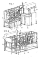
- figure 1 : vue d'ensemble en trois dimensions d'une machine selon l'invention, côté opérateur,
- figure 2 : vue d'ensemble en trois dimensions de la machine de la figure 1, côté opposé à l'opérateur,
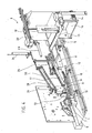
- figure 3 : vue de dessus des moyens de dépose d'une cale ou d'une cartonnette sur la machine des figures 1 et 2,
- figure 4 : vue de détail des moyens de dépose d'une cale ou d'une cartonnette sur la machine des figures 1 et 2,
- figure 5 : croquis d'un « fagot » de cales.
- FIG. 1: three-dimensional overview of a machine according to the invention, operator side,
- FIG. 2: three-dimensional overview of the machine of FIG. 1, side opposite the operator,
- FIG. 3: top view of the means for removing a block or a cardboard box on the machine of FIGS. 1 and 2,
- FIG. 4: detailed view of the means for removing a block or a cardboard box on the machine of FIGS. 1 and 2,
- Figure 5: sketch of a "bundle" of wedges.
On décrit d'abord un premier mode de fonctionnement d'une machine selon l'invention à savoir la dépose de cales rectangulaires. Dans ce cas, les opérations subies par un lot (1) de briques (2) entre les opérations de remplissage bouchage et l'entrée dans une filmeuse non représentée sont successivement les suivantes.We first describe a first mode of operation of a machine according to the invention, namely the removal of rectangular shims. In this case, the operations suffered by a batch (1) of bricks (2) between the filling and capping operations the entry into a film-maker not shown are successively the following.
Un lot (1) après remplissage bouchage, est transporté classiquement, par un convoyeur gravitaire, puis amené au poste de dépose (4) par deux convoyeurs à bande (5, 6) (voir figure 3).A batch (1) after filling corking, is conventionally transported by a gravity conveyor, then brought to the deposit station (4) by two conveyors to strip (5, 6) (see Figure 3).
Le premier convoyeur, ou convoyeur cadenseur (5) a pour fonction d'espacer les lots (1) qui sont déjà disposés les uns derrière les autres et perpendiculairement au déplacement, bouchons (7) sur le dessus.The first conveyor, or cadence conveyor (5) has the function of spacing the lots (1) which are already arranged one behind the other and perpendicularly when moving, plugs (7) on top.
A cet effet on prévoit, entre le convoyeur cadenseur (5) et le deuxième convoyeur, ou convoyeur retourneur, une cellule de barrage (non référencée) pour arrêter le convoyeur cadenseur (5) à chaque passage d'un lot, créant ainsi un espacement prédéterminé entre deux lots successifs.For this purpose provision is made, between the cadating conveyor (5) and the second conveyor, or return conveyor, a barrier cell (not referenced) for stop the cadating conveyor (5) at each passage of a batch, thus creating a predetermined spacing between two successive batches.
Le deuxième convoyeur, dit convoyeur retourneur (6) fait pivoter le lot de briques de 90° sur un pivot (11) situé à l'entrée du convoyeur retourneur et le lot se trouve à présent posé longitudinalement selon l'axe de déplacement du convoyeur retourneur. Les bouchons (7) sont en saillies sur la face supérieure du lot et disposés selon deux lignes latérales en saillies entre lesquelles sera déposée une cale rectangulaire comme expliqué plus loin.The second conveyor, called the reversing conveyor (6), rotates the batch of 90 ° bricks on a pivot (11) located at the entrance of the turning conveyor and the batch is now located longitudinally along the axis of movement of the conveyor turner. The plugs (7) protrude from the upper face of the batch and arranged along two projecting lateral lines between which a rectangular wedge as explained below.
On prévoit, sur le convoyeur retourneur (6) des moyens de guidage latéral (12) des lots de manière à aligner ceux-ci sous la cale à déposer et sous un convoyeur de distribution de cales (10) du poste de dépose (4) tandis qu'une cale se présente en sortie dudit distributeur (10).Lateral guide means (12) are provided on the reversing conveyor (6) batches so as to align them under the hold to be deposited and under a conveyor distribution of shims (10) of the depositing station (4) while a shim is present at the outlet of said distributor (10).
Lors de la présence du lot devant une deuxième cellule, celle-ci autorise le convoyage de ladite cale (9) par un convoyeur de cales (10) en sortie du poste de dépose (4).When the batch is present in front of a second cell, this authorizes the conveying of said hold (9) by a hold conveyor (10) at the outlet of the removal (4).
Ladite cale est déposée à la volée sur le lot de briques en sortie du convoyeur de cale ; celle-ci autorise la levée d'un bras (8) permettant de mettre en contact le lot (1) avec un ruban adhésif disposé dans un magasin à ruban (13).Said wedge is deposited on the fly on the batch of bricks at the outlet of the conveyor hold; this authorizes the lifting of an arm (8) making it possible to bring the lot (1) with adhesive tape placed in a tape store (13).
L'ensemble lot-cale entraíne alors l'extrémité du ruban adhésif.The lot-hold assembly then drives the end of the adhesive tape.
Lors de la présente de fin de passage de l'ensemble (lot-cale) devant troisième cellule, le ruban adhésif est coupé, puis devant une quatrième cellule, un bras de collage (19) avec galet en caoutchouc applique ledit ruban derrière le lot.During the present end of passage of the whole (lot-hold) before third cell, the adhesive tape is cut, then in front of a fourth cell, an arm of bonding (19) with rubber roller applies said tape behind the batch.
La cale est à présent fixée sur le lot.The wedge is now attached to the lot.
On décrit à présent en détail les moyens essentiels du poste de dépose (4)We now describe in detail the essential means of the drop-off station (4)
Un poste de dépose (4) selon l'invention (voir figure 4) comporte les moyens essentiels suivants :
- un magasin inférieur de cales (14),
- un magasin supérieur de cales (15),
- une table de chargement (16),
- un ensemble de moyens de dépilage et de poussée (23, 24, 25) d'une cale,
- un tunnel de réception (17),
- un ensemble de dépose des cales sur un lot de briques comportant un convoyeur de cales (10) des moyens de guidage (12) et de centrage du lot de briques prévus sur le convoyeur (6) de la machine,
- une armoire de puissance (26) et une armoire de commande (27).
- a lower wedge magazine (14),
- an upper wedge store (15),
- a loading table (16),
- a set of unstacking and pushing means (23, 24, 25) of a wedge,
- a reception tunnel (17),
- an assembly for depositing the shims on a batch of bricks comprising a shim conveyor (10) means for guiding (12) and centering the batch of bricks provided on the conveyor (6) of the machine,
- a power cabinet (26) and a control cabinet (27).
Les magasins de cales (14,15) sont des caissons parallélépipédiques ouvrables, par exemple au moyen d'une porte latérale amovible (21) dont la présence est par exemple détectée par un aimant codé ou un contact de sécurité à clé.The hold stores (14,15) are parallelepipedic boxes openable, for example by means of a removable side door (21), the presence is for example detected by a coded magnet or a safety contact to key.
Les magasins sont préférentiellement conçus pour recevoir des cales de trois longueurs différentes, pouvant s'adapter à des lots de trois longueurs différentes, selon le nombre de briques assemblées (4 ou 6 ou 8).The stores are preferably designed to receive shims of three different lengths, which can be adapted to batches of three different lengths, depending on the number of bricks assembled (4 or 6 or 8).
Les cales sont de préférences présentées assemblées en paquets appelés « fagots » (22), et composés de plusieurs colonnes de cales empilées, permettant une autonomie de durée prédéterminée.The shims are preferably presented assembled in packages called "Bundles" (22), and composed of several columns of stacked wedges, allowing autonomy of predetermined duration.
Lorsque le magasin inférieur (15) est chargé d'un fagot (22), que la porte (21) est fermée et qu'un opérateur a validé le chargement, la table de chargement (16) entraínée par un vérin monte jusqu'à sa position haute.When the lower magazine (15) is loaded with a bundle (22), than the door (21) is closed and an operator has validated the loading, the loading table (16) driven by a jack rises to its upper position.
La machine comporte donc un vérin montant la table de chargement jusqu'à sa position haute, après que le magasin inférieur ait été chargé d'un fagot (22), et que la porte ait été fermée.The machine therefore has a jack which raises the loading table to its high position, after the lower magazine has been loaded with a bundle (22), and the door was closed.
En fonction du format de cales, une plaque de poussée mobile (18) va pousser transversalement le fagot vers le magasin supérieur (15').Depending on the size of the shims, a mobile push plate (18) will push transversely the bundle towards the upper magazine (15 ').
La table de chargement peut redescendre et être de nouveau chargée.The loading table can come down and be loaded again.
Ensuite, une plaque de poussée longitudinale (18) va pousser le fagot jusqu'à une cellule.Then, a longitudinal push plate (18) will push the bundle up a cell.
Un pousseur latéral (20) transfert une colonne de cales dans le distributeur de cales (10).A lateral pusher (20) transfers a column of shims into the distributor shims (10).
Lors de ce transfert, un vérin bloqueur (23) est en position sortie pendant le transfert de colonne et en position rentrée pendant le dépilage.During this transfer, a blocking cylinder (23) is in the extended position during the column transfer and in the retracted position during unstacking.
Un vérin presseur vertical (24) descend afin de presser la rangée de cales et d'assurer un dépilage de cales sans bourrage ni blocage des cales.A vertical pressure cylinder (24) descends to press the row of shims and ensure unstacking of shims without jamming or blocking of the shims.
Un vérin pousseur de cales (25) permet de pousser une cale de la colonne dépilée pour la déposer dans un tunnel articulé (17).A wedge pusher cylinder (25) pushes a wedge from the column unstacked to deposit it in an articulated tunnel (17).
Une fois la cale déposée dans ce tunnel articulé, le vérin bloqueur (23) se met en position basse et un jet d'air pousse longitudinalement la cale à l'intérieur du tunnel articulé, puis sous le convoyeur de distribution cale (10).Once the wedge has been deposited in this articulated tunnel, the blocking cylinder (23) starts in the low position and an air jet pushes the wedge longitudinally inside the articulated tunnel, then under the wedge distribution conveyor (10).
Lors de l'arrivée d'un lot de briques devant une cellule, le convoyeur de cales (10) entraíne la cale qui sort du tunnel et la pose à la même vitesse que le convoyeur retourneur (5) qui emmène le lot, afin de la déposer sur la face supérieure dudit lot. When a batch of bricks arrives in front of a cell, the hold conveyor (10) drives the wedge that comes out of the tunnel and lays it at the same speed as the return conveyor (5) which takes the batch in order to deposit it on the face superior of said lot.
La cale est posée sur le dessus d'un lot de briques et entre les deux lignes de bouchons puis aussitôt fixée par le ruban adhésif sur le lot de briques.The wedge is placed on top of a batch of bricks and between the two lines of plugs then immediately fixed by the adhesive tape on the batch of bricks.
En même temps, le convoyeur de cale (10) entraíne la cale suivante, et le tunnel articulé est de nouveau chargé, etc...At the same time, the hold conveyor (10) drives the following hold, and the articulated tunnel is loaded again, etc ...
On décrit à présent un deuxième mode de fonctionnement de la machine selon l'invention à savoir la dépose d'une cartonnette sur un lot et servant de poignée.A second mode of operation of the machine is now described according to the invention namely the removal of a cardboard on a lot and serving as a handle.
Le poste de dépose cale (4) n'est pas utilisé dans ce mode de fonctionnement.The bilge depositing station (4) is not used in this operating mode.
Le convoyeur cadenceur (5) conserve sa fonction d'espacer les lots qui sont déjà disposés les uns derrière les autres et perpendiculairement au déplacement.The timing conveyor (5) retains its function of spacing the lots which are already arranged one behind the other and perpendicular to the movement.
En l'absence de pivot (11) le deuxième convoyeur (6) fait avancer le lot de briques à travers l'ensemble de dépose cale sans le faire pivoter de 90°.In the absence of a pivot (11) the second conveyor (6) advances the batch of bricks through the wedge removal assembly without rotating it 90 °.
Lors de l'arrivée d'un lot de briques devant une cellule, celle-ci autorise la levée du bras (8) permettant de mettre en contact le lot avec le ruban adhésif.When a batch of bricks arrives in front of a cell, it authorizes the lifting of the arm (8) enabling the batch to be brought into contact with the adhesive tape.
En même temps, une cartonnette (28) d'un magasin de cartonnettes (30) est distribuée à l'aide d'un vérin pour cartonnette (29) et sur ledit ruban adhésif.At the same time, a carton (28) from a carton store (30) is distributed using a cardboard cylinder (29) and on said adhesive tape.
L'ensemble (lot de briques) avance et entraíne le ruban adhésif;The assembly (batch of bricks) advances and drives the adhesive tape;
Lors de la présence de fin de passage de l'ensemble (lot-cartonnette) devant une cellule, le ruban est coupé (7). Puis, devant une autre cellule, un bras aspirant (11) se lève en aspirant le ruban avec la cartonnette afin de former un espace d'environ 10 mm entre la cartonnette et le dessus du lot afin que le client final puisse passer les doigts pour porter le lot.During the presence of the end of passage of the assembly (lot-cardboard) in front a cell, the ribbon is cut (7). Then, in front of another cell, an aspiring arm (11) rises by sucking the ribbon with the cardboard to form a space about 10 mm between the cardboard and the top of the batch so that the end customer can pass the fingers to carry the lot.
Enfin, devant une autre cellule, le bras de collage (19) avec galet en caoutchouc applique le ruban derrière le lot.Finally, in front of another cell, the bonding arm (19) with roller in rubber applies the tape behind the lot.
Le lot de briques est ensuite retourné à 90° en sortie du convoyeur retourneur (5) par un pivot non représenté.The batch of bricks is then turned 90 ° at the exit of the turning conveyor (5) by a pivot not shown.
L'invention voit son application à la dépose et à la fixation en continu et à cadence élevée, d'objets plats empilables, c'est-à-dire en forme de plaque de contour non obligatoirement rectangulaire, sur une surface plane d'un lot de contenants tel que par exemple, un lot de briques, de bouteilles ou autres, ceci avant leur passage dans une filmeuse.The invention sees its application to the continuous removal and fixing and to high rate, stackable flat objects, i.e. plate-shaped contour not necessarily rectangular, on a flat surface of a batch of containers such as for example, a batch of bricks, bottles or the like, this before their passage in a filming machine.
La machine selon l'invention est apte à fonctionner aux cadences élevées en usage dans les installations de remplissage de bouteilles, briques ou autres lignes d'embouteillage.The machine according to the invention is capable of operating at high rates in use in filling systems for bottles, bricks or other lines bottling.
Ladite machine n'est en aucun cas un palettiseur, mais une machine de dépose de cales et poignées sur un contenant dont les dimensions maximales approximatives sont les suivantes : longueur 384 mm - hauteur 250 mm - largeur 130 mm. La particularité étant la cadence puisque la dépose et la fixation s'effectuent à la même cadence que celle du défilement des lots qui à titre d'exemple peut atteindre 1500 déposes par heure.Said machine is in no case a palletizer, but a depositing machine holds and handles on a container with maximum dimensions approximate are as follows: length 384 mm - height 250 mm - width 130 mm. The particularity being the pace since the removal and fixing are carried out at the same rate as that of the scrolling of the batches which example can reach 1,500 deposits per hour.
Claims (12)
Applications Claiming Priority (2)
| Application Number | Priority Date | Filing Date | Title |
|---|---|---|---|
| FR0211427 | 2002-09-16 | ||
| FR0211427A FR2844502B1 (en) | 2002-09-16 | 2002-09-16 | MACHINE FOR REMOVAL AND FIXATION OF FLAT OBJECTS ON LOTS OF CONTAINERS |
Publications (1)
| Publication Number | Publication Date |
|---|---|
| EP1398272A1 true EP1398272A1 (en) | 2004-03-17 |
Family
ID=31726060
Family Applications (1)
| Application Number | Title | Priority Date | Filing Date |
|---|---|---|---|
| EP03366007A Withdrawn EP1398272A1 (en) | 2002-09-16 | 2003-09-15 | Machine for depositing and fixing flat objects on container batches |
Country Status (2)
| Country | Link |
|---|---|
| EP (1) | EP1398272A1 (en) |
| FR (1) | FR2844502B1 (en) |
Citations (4)
| Publication number | Priority date | Publication date | Assignee | Title |
|---|---|---|---|---|
| US3923145A (en) * | 1972-11-17 | 1975-12-02 | Grapha Holding Ag | Apparatus for placing cover sheets on stacks of different heights |
| US4050577A (en) * | 1973-09-04 | 1977-09-27 | North State Pyrophyllite Company | Refractory structure and method |
| US4897980A (en) * | 1989-06-05 | 1990-02-06 | James River Corporation | Apparatus for forming a bulk package |
| EP0452560A1 (en) * | 1990-04-20 | 1991-10-23 | Italo Meneghetti | Packing machine for paper or cardboard packets and the like |
-
2002
- 2002-09-16 FR FR0211427A patent/FR2844502B1/en not_active Expired - Fee Related
-
2003
- 2003-09-15 EP EP03366007A patent/EP1398272A1/en not_active Withdrawn
Patent Citations (4)
| Publication number | Priority date | Publication date | Assignee | Title |
|---|---|---|---|---|
| US3923145A (en) * | 1972-11-17 | 1975-12-02 | Grapha Holding Ag | Apparatus for placing cover sheets on stacks of different heights |
| US4050577A (en) * | 1973-09-04 | 1977-09-27 | North State Pyrophyllite Company | Refractory structure and method |
| US4897980A (en) * | 1989-06-05 | 1990-02-06 | James River Corporation | Apparatus for forming a bulk package |
| EP0452560A1 (en) * | 1990-04-20 | 1991-10-23 | Italo Meneghetti | Packing machine for paper or cardboard packets and the like |
Also Published As
| Publication number | Publication date |
|---|---|
| FR2844502B1 (en) | 2005-05-13 |
| FR2844502A1 (en) | 2004-03-19 |
Similar Documents
| Publication | Publication Date | Title |
|---|---|---|
| EP2089280A1 (en) | Packing and packaging system | |
| WO2019228901A1 (en) | Transfer of products in a gripped manner to or from an accumulation surface | |
| CA2408533C (en) | Transfer apparatus and method for film bags | |
| EP2204342A1 (en) | Method for grouping bottles | |
| WO2018167437A1 (en) | Production of batches of products for palletizing in layers | |
| EP0243236A1 (en) | Apparatus for transferring objects, in particular glass panes | |
| FR3049933A1 (en) | SYSTEM AND METHOD FOR HANDLING ARTICLES SUCH AS BEVERAGE CONTAINERS OR THE LIKE | |
| FR2738559A1 (en) | DEVICE FOR STACKING LAYERS ON A PALLET AND PALLETING DEVICE | |
| FR2954755A1 (en) | METHOD FOR ORIENTATION AND GROUPING OF PRODUCTS FOR THEIR COLLECTION | |
| US3962845A (en) | Apparatus for counting and packaging can ends | |
| EP2178781B1 (en) | System for depositing documents into boxes | |
| FR2896230A1 (en) | METHOD AND GROUPING STATION FOR PILGRIM. | |
| EP1398272A1 (en) | Machine for depositing and fixing flat objects on container batches | |
| EP0334769B1 (en) | Machine for loading and unloading articles, arranged in layers | |
| EP4031454A1 (en) | Device and method for forming a container by folding | |
| FR3088315A1 (en) | DEVICE FOR CONVEYING PRODUCTS AND METHOD FOR MANAGING THE TRANSFER OF SAID PRODUCTS | |
| EP1147059A1 (en) | Palletizing device for piles of printed booklets | |
| EP0562197B1 (en) | Method and device for palletizing parcels | |
| FR2473998A1 (en) | CASSETTE STORE FOR FEEDING MACHINES FOR WINDING MAGNETIC STRIPS | |
| EP4041539A1 (en) | Device and method for forming a container by folding | |
| FR2673922A1 (en) | Method and device for palletising parcels | |
| FR2617799A1 (en) | METHOD AND AUTOMATIC MACHINE FOR GROUPING AND STORING CONTAINERS SUCH AS POTS OR THE LIKE | |
| WO1994026594A1 (en) | Method and device for packaging cans or the like by grouping together using blanks | |
| FR2602207A1 (en) | Device for transferring stacks of cups, of a predetermined length, from a conveyor belt to a cardboard box, or vice versa | |
| FR2718422A1 (en) | Handling and interim storage bay for dispatch packing |
Legal Events
| Date | Code | Title | Description |
|---|---|---|---|
| PUAI | Public reference made under article 153(3) epc to a published international application that has entered the european phase |
Free format text: ORIGINAL CODE: 0009012 |
|
| AK | Designated contracting states |
Kind code of ref document: A1 Designated state(s): AT BE BG CH CY CZ DE DK EE ES FI FR GB GR HU IE IT LI LU MC NL PT RO SE SI SK TR |
|
| AX | Request for extension of the european patent |
Extension state: AL LT LV MK |
|
| 17P | Request for examination filed |
Effective date: 20040917 |
|
| AKX | Designation fees paid |
Designated state(s): AT BE BG CH CY CZ DE DK EE ES FI FR GB GR HU IE IT LI LU MC NL PT RO SE SI SK TR |
|
| STAA | Information on the status of an ep patent application or granted ep patent |
Free format text: STATUS: THE APPLICATION IS DEEMED TO BE WITHDRAWN |
|
| 18D | Application deemed to be withdrawn |
Effective date: 20060320 |