EP1401162A2 - Packet communication terminal, packet communication system, packet communication method and packet communication program - Google Patents
Packet communication terminal, packet communication system, packet communication method and packet communication program Download PDFInfo
- Publication number
- EP1401162A2 EP1401162A2 EP20030021334 EP03021334A EP1401162A2 EP 1401162 A2 EP1401162 A2 EP 1401162A2 EP 20030021334 EP20030021334 EP 20030021334 EP 03021334 A EP03021334 A EP 03021334A EP 1401162 A2 EP1401162 A2 EP 1401162A2
- Authority
- EP
- European Patent Office
- Prior art keywords
- communication terminal
- packet
- packet communication
- network address
- network
- Prior art date
- Legal status (The legal status is an assumption and is not a legal conclusion. Google has not performed a legal analysis and makes no representation as to the accuracy of the status listed.)
- Granted
Links
Images


Classifications
-
- H—ELECTRICITY
- H04—ELECTRIC COMMUNICATION TECHNIQUE
- H04W—WIRELESS COMMUNICATION NETWORKS
- H04W8/00—Network data management
- H04W8/02—Processing of mobility data, e.g. registration information at HLR [Home Location Register] or VLR [Visitor Location Register]; Transfer of mobility data, e.g. between HLR, VLR or external networks
- H04W8/08—Mobility data transfer
- H04W8/14—Mobility data transfer between corresponding nodes
-
- H—ELECTRICITY
- H04—ELECTRIC COMMUNICATION TECHNIQUE
- H04W—WIRELESS COMMUNICATION NETWORKS
- H04W80/00—Wireless network protocols or protocol adaptations to wireless operation
- H04W80/04—Network layer protocols, e.g. mobile IP [Internet Protocol]
Definitions
- the present invention relates to a packet communication terminal, a packet communication system, a packet communication method, and a packet communication program.
- packet communication terminals carried by users are spreading as typified by mobile communication terminals and others.
- the packet communication terminals subject to movement like the mobile communication terminals migrate among communication areas established by base stations belonging to different networks.
- the packet communication terminal is assigned different network addresses in the respective networks connected before and after the migration.
- Mobile-IP is known as a technique of enabling the packets communication terminal assigned the different addresses before and after the migration as described, to communicate with a correspondent packet communication terminal.
- a home agent which is a management node in a home network (HN) as a network to which the packet communication terminal originally belongs
- a foreign agent FA
- FN foreign network
- This agent advertisement is provided with the Life-Time field. For example, let us suppose a case where a packet communication terminal migrates from its HN to a certain FN. When the packet communication terminal fails to receive a new agent advertisement from the HN even after an elapsed time indicated in the Life-Time field of the agent advertisement received last in the HN, it acknowledges that it has moved off the HN.
- the packet communication terminal receives an agent advertisement in the staying FN, and it acknowledges that it has moved into the FN. Then the packet communication terminal proceeds to the following registration process in order to implement packet communication in the staying FN.
- this registration process first, the packet communication terminal sends a registration request to the FA. This registration request is sent with a c/o (care-of) address of the packet communication terminal in the FN from the FA to the HA. Then the HA registers the c/o address of the packet communication terminal and the network address of the packet communication terminal in correlation with each other, and then sends a registration response to the FA. This registration response is forwarded from the FA to the packet communication terminal to be received by the packet communication terminal, thus completing the registration process.
- the HA adds the c/o address to this packet, encapsulates it, and then forwards the encapsulated packet to the FA.
- the FA removes the c/o address from the packet and sends the packet to the packet communication terminal.
- Mobile-IP as described above implements the packet communication from the correspondent packet communication terminal to the migrating packet communication terminal.
- the migrating packet communication terminal is unable to receive a packet transmitted from the correspondent packet communication terminal during a period between a time when it has received the last agent advertisement in the network before the migration and a time of completion of the aforementioned registration process.
- a technique of decreasing the period in which the packet communication terminal is unable to receive any packet because of the migration is a technique of decreasing the above-described packet undelivered period by letting a base station controller perform the aforementioned registration process with the HA at a time of completion of a handover process executed on the occasion of a migration between base stations (e.g., Japanese Patent Application Laid-Open No. 2002-191066).
- the present invention has been accomplished in order to solve the above problem and an object of the present invention is to provide a packet communication terminal, a packet communication system, a packet communication method, and a packet communication program capable of implementing delay-free packet communication with a correspondent packet communication terminal even during migration between different networks.
- a packet communication terminal for packet communication comprising: network address acquiring means for acquiring a network address of the packet communication terminal from a network to which the packet communication terminal can be connected; network address storing means for storing the network address acquired by the network address acquiring means; network address notifying means for notifying a correspondent packet communication terminal of the network address stored in the network address storing means; and first packet receiving means for receiving a packet sent from the correspondent packet communication terminal to the network address; wherein when there exist a plurality of networks to which the packet communication terminal can be connected, the network address acquiring means acquires a plurality of aforesaid network addresses from the respective networks; wherein the network address storing means stores the plurality of network addresses; wherein the network address notifying means notifies the correspondent packet communication terminal of the plurality of network addresses; and wherein the first packet receiving means receives packets generated from identical data and sent from the correspondent packet communication terminal to the respective network addresses.
- a packet communication program for letting a packet communication terminal function as: network address acquiring means for acquiring a network address of the packet communication terminal from a network to which the packet communication terminal can be connected; network address storing means for storing the network address acquired by the network address acquiring means; network address notifying means for notifying a correspondent packet communication terminal of the network address stored in the network address storing means; and first packet receiving means for receiving a packet sent from the correspondent packet communication terminal to the network address; wherein when there exist a plurality of networks to which the packet communication terminal can be connected, the network address acquiring means acquires a plurality of aforesaid network addresses from the respective networks; wherein the network address storing means stores the plurality of network addresses; wherein the network address notifying means notifies the correspondent packet communication terminal of the plurality of network addresses; and wherein the first packet receiving means receives packets generated from identical data and sent from the correspondent packet communication terminal to the respective network addresses.
- a packet communication terminal for packet communication comprising: destination network address storing means for storing a network address notified of by a correspondent packet communication terminal, as a destination network address; second packet generating means for generating a packet from data to be transmitted to the correspondent packet communication terminal; and second pocket transmitting means for transmitting the packet to the correspondent packet communication terminal; wherein when a plurality of aforesaid network addresses are notified of by the correspondent packet communication terminal, the destination network address storing means stores a plurality of aforesaid destination network addresses corresponding to the plurality of network addresses; and wherein when a plurality of aforesaid a destination network addresses are stored in the destination network address storing means, the second packet transmitting means transmits aforesaid packets generated from identical data, to the respective destination network addresses.
- a packet communication program is a packet communication program for letting a packet communication terminal function as: destination network address storing means for storing a network address notified of by a correspondent packet communication terminal, as a destination network address; second packet generating means for generating a packet from data to be transmitted to the correspondent packet communication terminal; and second packet transmitting means for transmitting the packet to the correspondent packet communication terminal; wherein when a plurality of aforesaid network addresses are notified of by the correspondent packet communication terminal, the destination network address storing means stores a plurality of aforesaid destination network addresses corresponding to the plurality of network addresses; and wherein when a plurality of aforesaid destination network addresses are stored in the destination network address storing means, the second packet transmitting means transmits aforesaid packets generated from identical data, to the respective destination network addresses.
- a packet communication system is a packet communication system for packet communication between, a first packet communication terminal and a second packet communication terminal
- the first packet communication terminal comprises: network address acquiring means for acquiring a network address of the packet communication terminal from a network to which the first packet communication terminal can be connected; network address storing means for storing the network address acquired by the network address acquiring means; network address notifying means for notifying the second packet communication terminal of the network address stored in the network address storing means; and first packet receiving means for receiving a packet sent from the second packet communication terminal to the network address
- the second packet communication terminal comprises: destination network address storing means for storing the network address notified of by the first packet communication terminal, as a destination network address; second packet generating means for generating a packet from data to be transmitted to the first packet communication terminal; and second packet transmitting means for transmitting the packet to the first packet communication terminal; wherein when there exist a plurality of networks to which the first packet communication terminal can be connected, the network
- a packet communication method is a packet communication method for packet communication between a first packet communication terminal and a second packet communication terminal, the packet communication method comprising: a network address acquiring step wherein network address acquiring means of the first packet communication terminal acquires a network address of the packet communication terminal from a network to which the first packet communication terminal can be connected; a network address storing step wherein network address storing means of the first packet communication terminal stores the network address acquired by the network address acquiring means; a network address notifying step wherein network address notifying means of the first packet communication terminal notifies the second packet communication terminal of the network address stored in the network address storing means; a destination network address storing step wherein destination network address storing means of the second packet communication terminal stores the network address notified of by the first packet communication terminal, as a destination network address; a first packet generating step wherein second packet generating means of the second packet communication terminal generates a packet from data to be transmitted to the first packet communication terminal; a first packet transmitting step
- the network address acquiring means acquires network addresses from the respective networks.
- the network address storing means stores these network addresses and the network address notifying means notifies the second packet communication terminal as a correspondent packet communication terminal of the network addresses.
- the destination network address storing means stores the network addresses thus notified of, as respective destination network addresses. Then the second packet transmitting means transmits packets generated from identical data by the second packet generating means, to the respective destination network addresses stored in the destination network address storing means.
- the first packet receiving mean receives the packets transmitted to the respective destination network addresses as described above, as packets generated from the identical data.
- the second packet communication terminal is made to transmit packets to the network addresses acquired from the respective networks, as described above. Even if the first packet communication terminal becomes no longer able to stay connected to any one of the networks because of further migration, it can also receive packets from the second packet communication terminal through the other networks without delay.
- the packets transmitted to the plurality of network addresses by the second packet transmitting means may be packets identical to each other.
- the packets transmitted to the plurality of network addresses by the second packet transmitting means may be packets identical to each other.
- the packets transmitted to the respective destination network addresses by the second packet transmitting means of the second packet communication terminal may be packets identical to each other.
- the second packet communication terminal when there are a plurality of destination network addresses notified of by the first packet communication terminal and stored in the destination network address storing means, the second packet communication terminal sends identical packets to the respective destination network addresses. Therefore, even if the first packet communication terminal becomes no longer able to stay connected to any one of the networks because of migration, the first packet communication terminal can receive packets transmitted to the network addresses assigned by the other networks. As a result, the first packet communication terminal can receive packets transmitted from the second packet communication terminal, without delay.
- the packet communication terminal of the present invention further comprises second redundant packet generating means for generating redundant packets by forward error correction codes from data part of the packets generated by the second packet generating means; and when a plurality of aforesaid destination network addresses are stored in the destination network address storing means, the second packet transmitting means distributes and transmits the packets generated by the second packet generating means and the redundant packets generated by the second redundant packet generating means, to the plurality of destination network addresses in such a manner that even in a case where any one of the destination network addresses becomes ineffective, the correspondent packet communication terminal can receive different packets in the number equal to or greater than the number of packets generated by the second packet generating means.
- second redundant packet generating means for generating redundant packets by forward error correction codes from data part of the packets generated by the second packet generating means
- the packet communication program of the present invention lets the packet communication terminal further function as: second redundant packet generating means for generating redundant packets by forward error correction codes from data part of the packets generated by the second packet generating means; and when a plurality of aforesaid destination network addresses are stored in the destination network address storing means, the second packet transmitting means distributes and transmits the packets generated by the second packet generating means and the redundant packets generated by the second redundant packet generating means, to the plurality of destination network addresses in such a manner that even in a case where any one of the destination network addresses becomes ineffective, the correspondent packet communication terminal can receive different packets in the number equal to or greater than the number of packets generated by the second packet generating means.
- second redundant packet generating means for generating redundant packets by forward error correction codes from data part of the packets generated by the second packet generating means
- the second packet transmitting means distributes and transmits the packets generated by the second packet generating means and the redundant packets generated by the second redundant packet generating means, to the plurality
- the second packet communication terminal further comprises second redundant packet generating means for generating redundant packets by forward error correction codes from data part of the packets generated by the second packet generating means; and when a plurality of aforesaid destination network addresses are stored in the destination network address storing means, the second packet transmitting means of the second packet communication terminal distributes and transmits the packets generated by the second packet generating means and the redundant packets generated by the second redundant packet generating means, to the plurality of destination network addresses in such a manner that even in a case where any one of the destination network addresses becomes ineffective, the first packet communication terminal can receive different packets in the number equal to or greater than the number of packets generated by the second packet generating means.
- the packet communication method of the present invention further comprises a first redundant packet generating step wherein second redundant packet generating means of the second packet communication terminal generates redundant packets by forward error correction codes from data part of the packets generated by the second packet generating means; and in the first packet transmitting step, when a plurality of aforesaid destination network addresses are stored in the destination network address storing means, the second packet transmitting means of the second packet communication terminal distributes and transmits the packets generated by the second packet generating means and the redundant packets generated by the second redundant packet generating means, to the plurality of destination network addresses in such a manner that even in a case where any one of the destination network addresses becomes ineffective, the first packet communication terminal can receive different packets in the number equal to or greater than the number of packets generated by the second packet generating means.
- the second packet communication terminal makes the second redundant packet generating means generate redundant packets by forward error correction codes from data part of packets. Then the second packet transmitting means distributes and transmits the redundant packets and the packets generated by the second packet generating means, to the respective destination network addresses. This distribution is effected in such a manner that even if any one of the above destination network addresses becomes ineffective, the first packet communication terminal can receive different packets in the number equal to or greater than the number of packets generated by the second packet generating means. Therefore, the first packet communication terminal can receive the packets in the number that permits recovery of the above data. As a result, the first packet communication terminal can receive packets transmitted from the second packet communication terminal, without delay.
- the packet communication terminal of the present invention further comprises ineffective network address notifying means for notifying the correspondent packet communication terminal of the network address acquired by the network address acquiring means from the network to which the packet communication terminal is no longer able to stay connected, and information that the network address is made ineffective.
- the packet communication program of the present invention lots the packet communication terminal further function as: ineffective network address notifying means for notifying the correspondent packet communication terminal of the network address acquired by the network address acquiring means from the network to which the packet communication terminal is no longer able to stay connected, and information that the network address is made ineffective.
- the destination network address storing means makes ineffective the destination network address corresponding to the network address.
- the destination network address storing means makes ineffective the destination network address corresponding to the network address.
- the first packet communication terminal further comprises ineffective network address notifying means for notifying the second packet communication terminal of the network address acquired by the network address acquiring means from the network to which the first packet communication terminal is no longer able to stay connected, and information that the network address is made ineffective; and based on the network address notified of by the first packet communication terminal and the information that the network address is made ineffective, the destination network address storing means of the second packet communication terminal makes ineffective the destination network address corresponding to the network address.
- the packet communication method of the present invention further comprises an ineffective network address notifying step wherein ineffective network address notifying means of the first packet communication terminal notifies the second packet communication terminal of the network address acquired by the network address acquiring means from the network to which the first packet communication terminal is no longer able to stay connected, and information that the network address is made ineffective; and a destination network address disabling step wherein, based on the network address notified of by the first packet communication terminal and the information that the network address is made ineffective, the destination network address storing means of the second packet communication terminal makes ineffective the destination network address corresponding to the network address.
- the first packet communication terminal makes the ineffective network address notifying means notify the second packet communication terminal of a network address acquired from a network to which the first packet communication terminal is no longer able to stay connected, together with information indicating the fact. Based on this notification, the second packet communication terminal makes ineffective the destination network address corresponding to the network address thus notified of, whereby it becomes feasible to cut down the waste that the second packet communication terminal sends packets to the network to which the first packet communication terminal is no longer able to stay connected.
- the packet communication terminal of the present invention further comprises radio wave intensity measuring means for, when a plurality of aforesaid network addresses are stored in the network address storing means, measuring intensities of radio waves from the respective networks from which the respective network addresses were acquired; and effective network address notifying means for, when a maximum intensity out of the intensities measured by the radio wave intensity measuring means is not less than a first predetermined threshold, notifying the correspondent packer communication terminal of the network address acquired by the network address acquiring means from the network having transmitted the radio wave of the maximum intensity, and information that a communication state with the aforesaid network is good.
- radio wave intensity measuring means for, when a plurality of aforesaid network addresses are stored in the network address storing means, measuring intensities of radio waves from the respective networks from which the respective network addresses were acquired
- effective network address notifying means for, when a maximum intensity out of the intensities measured by the radio wave intensity measuring means is not less than a first predetermined threshold, notifying the correspondent packer communication terminal of the network address acquired by
- the packet communication program of the present invention lets the packet communication terminal further function as: radio wave intensity measuring means for, when a plurality of aforesaid network addresses are stored in the network address storing means, measuring intensities of radio waves from the respective networks from which the respective network addresses were acquired; and effective network address notifying means for, when a maximum intensity out of the intensities measured by the radio wave intensity measuring means is not less than a first predetermined threshold, notifying the correspondent packet communication terminal of the network address acquired by the network address acquiring means from the network having transmitted the radio wave of the maximum intensity, and information that a communication state with the aforesaid network is good.
- radio wave intensity measuring means for, when a plurality of aforesaid network addresses are stored in the network address storing means, measuring intensities of radio waves from the respective networks from which the respective network addresses were acquired
- effective network address notifying means for, when a maximum intensity out of the intensities measured by the radio wave intensity measuring means is not less than a first predetermined threshold, notifying the correspondent packet communication terminal of
- the second packet transmitting means transmits aforesaid packets to the destination network address stored corresponding to the network address in the destination network address storing means.
- the second packet transmitting means transmits aforesaid packets to the destination network address stored corresponding to the network address in the destination network address storing means.
- the packet communication system of the present invention further comprises radio wave intensity measuring means for, when a plurality of aforesaid network addresses are stored in the network address storing means, measuring intensities of radio waves from the respective networks from which the respective network addresses were acquired; and effective network address notifying meens for, when a maximum intensity out of the intensities measured by the radio wave intensity measuring means is not less than a first predetermined threshold, notifying the second packet communication terminal of the network address acquired by the network address acquiring means from the network having transmitted the radio wave of the maximum intensity, and information that a communication state with the aforesaid network is good; and when a plurality of aforesaid destination addresses are stored in the destination address storing means, based on the network address notified of by the first packet communication terminal, and the information that a communication state with the network from which the aforesaid network address was acquired is good, the second packet transmitting means of the second packet communication terminal transmits aforesaid packets to the destination network address stored corresponding to the
- the packet communication method of the present invention further comprises a radio wave intensity measuring step wherein when a plurality of aforesaid network addresses are stored in the network address storing means, radio wave intensity measuring means of the first packet communication terminal measures intensities of radio waves from the respective networks from which the respective network addresses were acquired; and an effective network address notifying step wherein when a maximum intensity out of the intensities measured by the radio wave intensity measuring means is not less than a first predetermined threshold, effective network address notifying means of the first packet communication terminal notifies the second packet communication terminal of the network address acquired by the network address acquiring means from the network having transmitted the radio wave of the maximum intensity, and information that a communication state witn the aforesaid network is good; and in the first packet transmitting step, when a plurality of aforesaid destination addresses are stored in the destination address storing means, based on the network address notified of by the first packet communication terminal, and the information that a communication state with the network from which the aforesaid network address was acquired is
- the first packet communication terminal when the first packet communication terminal is connected to two or more networks, the first packet communication terminal makes the radio wave intensity measuring means measure intensities of radio waves from the respective networks.
- the effective network address notifying means notifies the second packet communication terminal of the network address acquired from the network having transmitted the radio wave of the maximum intensity, and the information that the communication state with the relevant network is good.
- the second packet communication terminal makes the second packet transmitting means transmit packets to the destination network address corresponding to the network address included in the above notification.
- the first packet communication terminal in the network transmitting the radio wave of the intensity being not less than the first predetermined threshold and being maximum among the multiple networks, it is assumed that the first packet communication terminal is located near a base station belonging to the network and is in a good communication state. Therefore, under a judgment that this connection state can be maintained for the time being, the second packet communication terminal transmits packets to the above destination network address notified of. Therefore, the first packet communication terminal can receive the packets transmitted from the second packet communication terminal, without delay and it is feasible to cut down the waste that the second packet communication terminal transmits packets through all the networks to which the first packet communication terminal can be connected.
- the packet communication terminal of the present invention further comprises communication state notifying means for, when all the intensities of the radio waves from the plurality of networks measured by the radio wave intensity measuring means are smaller than a second predetermined threshold, notifying the correspondent packet communication terminal of information that there is no network from that the packet communication terminal can receive a radio wave of not less than the second predetermined threshold.
- the packet communication program of the present invention lets the packet communication terminal further function as: communication state notifying means for, when all the intensities of the radio waves from the plurality of networks measured by the radio wave intensity measuring means are smaller than a second predetermined threshold, notifying the correspondent packet communication terminal of information that there is no network from the the packet communication terminal can receive a radio wave of not less than the second predetermined threshold.
- the second packet transmitting means transmits the packets to the respective destination network addresses stored in the destination network address storing means.
- the second packet transmitting means transmits the packets to the respective destination network addresses stored in the destination network address storing means.
- the first packet communication terminal further comprises communication state notifying means for, when all the intensities of the radio waves from the plurality of networks measured by the radio wave intensity measuring means are smaller than a second predetermined threshold, notifying the second packet communication terminal of information that there is no network from that the first packet communication terminal can receive a radio wave of not less than the second predetermined threshold; and based on the information that there is no network from that the first packet communication terminal can receive a radio wave of not less than the second predetermined threshold, notified of by the first packet communication terminal, the second packet transmitting means of the second packet communication terminal transmits the packets to the respective destination network addresses stored in the destination network address storing means.
- the packet communication method of the present invention further comprises a communication state notifying step wherein when all the intensities of the radio waves from the plurality of networks measured by the radio wave intensity measuring means are smaller than a second predetermined threshold, communication state notifying means of the first packet communication terminal notifies the second packet communication terminal of information that there is no network from that the first packet communication terminal can receive a radio wave of not less than the second predetermined threshold; and in the first packet transmitting step, based on the information that there is no network from that the first packet communication terminal can receive a radio wave of not less than the second predetermined threshold, notified of by the first packet communication terminal, the second packet transmitting means of the second packet communication terminal transmits the packets to the respective destination network addresses stored in the destination network address storing means.
- a communication state notifying step wherein when all the intensities of the radio waves from the plurality of networks measured by the radio wave intensity measuring means are smaller than a second predetermined threshold, communication state notifying means of the first packet communication terminal notifies the second packet communication terminal of information that there is no network
- the first packet communication terminal when the intensities of the radio waves from the respective networks measured by the above radio wave intensity measuring means are smaller than the second predetermined threshold, the first packet communication terminal makes the communication state notifying means notify the second packet communication terminal of the information indicating that fact.
- the second packet communication terminal transmits packets to the respective destination network addresses stored in the destination network address storing means, based on the notification. Namely, when the intensities of the radio waves from the respective networks measured by the radio wave intensity measuring means are smaller than the second predetermined threshold, it is determined that the first packet communication terminal is located in a boundary region among communication areas of the respective networks, and thus the second packet communication terminal transmits packets to the respective destination network addresses corresponding to the respective network addresses acquired from these networks by the first packet communication terminal. Even if the first packet communication terminal moves from the boundary region among networks to become no longer be able to stay connected to any one of the networks, the first packet communication terminal can still receive packets transmitted through the other networks from the second packet communication terminal, without delay.
- another packet communication terminal is a packet communication terminal for packet communication comprising: network address acquiring means for acquiring a network address of the packet communication terminal from a network to which the packet communication terminal can be connected; network address scoring means for storing the network address acquired by the network address acquiring means; network address notifying means for notifying a correspondent packet communication terminal of the network address stored in the network address storing means; first packet generating means for generating a packet from data to be transmitted to the correspondent packet communication terminal; and first packet transmitting means for providing the packet with the network address stored in the network address storing means and for transmitting the packet to the correspondent packet communication terminal; wherein when there exist a plurality of networks to which the packet communication terminal can be connected, the network address acquiring means acquires a plurality of aforesaid network addresses from the respective networks; wherein the network address storing means stores the plurality of network addresses; wherein the network address notifying means notifies the correspondent packet communication terminal of the plurality of network addresses; and wherein when there exist a plurality of networks to which the packet communication
- another packet communication program is a packet communication program for letting a packet communication terminal function as: network address acquiring means for acquiring a network address of the packet communication terminal from a network to which the packet communication terminal can be connected; network address storing means for storing the network address acquired by the network address acquiring means; network address notifying means for notifying a correspondent packet communication terminal of the network address stored in the network address Storing means; first packet generating means for generating a packet from data to be transmitted to the correspondent packet communication terminal; and first packet transmitting means for providing the packet with the network address stored in the network address storing means and for transmitting the packet to the correspondent packet communication terminal; wherein when there exist a plurality of networks to which the packet communication terminal can be connected, the network address acquiring means acquires a plurality of aforesaid network addresses from the respective networks; wherein the network address storing means stores the plurality of network addresses; wherein the network address notifying means notifies the correspondent packet communication terminal of the plurality of network addresses
- another packet communication terminal is a packet communication terminal for packet communication comprising: destination network address storing means for storing a network address notified of by a correspondent packet communication terminal, as a destination network address; and second packet receiving means for receiving a packet transmitted from the correspondent packet communication terminal; wherein when a plurality of aforesaid network addresses are notified of by the correspondent packet communication terminal, the destination network address storing means stores a plurality of aforesaid destination network addresses corresponding to the respective network addresses; and wherein the second packet receiving means receives a packet transmitted from the correspondent packet communication terminal, provided with one of the plurality of destination network addresses, and generated from identical data.
- another packet communication program is a packet communication program for letting a packet communication terminal function as: destination network address storing means for storing a network address notified of by a correspondent packet communication terminal, as a destination network address; and second packet receiving means for receiving a pocket transmitted from the correspondent packet communication terminal; wherein when a plurality of aforesaid network addresses are notified of by the correspondent packet communication terminal the destination network address storing means stores a plurality of aforesaid destination network addresses corresponding to the respective network addresses; and wherein the second packet receiving means receives a packet transmitted from the correspondent packet communication terminal provided with one of the plurality of destination network addresses, and generated from identical data.
- another packet communication system is a packet communication system for packet communication between a first packet communication terminal and a second packet communication terminal
- the first packet communication terminal comprises: network address acquiring means for acquiring a network address of the packet communication terminal from a network to which the first packet communication terminal can be connected; network address storing means for storing the network address acquired by the network address acquiring means; network address notifying means for notifying the second packet communication terminal of the network address stored in the network address storing means; first packet generating means for generating a packet from data to be transmitted to the second packet communication terminal; and first packet transmitting means for providing the packet with the network address stored in the network address storing means and for transmitting the packet to the second packet communication terminal;
- the second packet communication terminal comprises: destination network address storing means for storing a network address notified of by the first packet communication terminal, as a destination network address; and second packet receiving means for receiving a packet transmitted from the first packet communication terminal; wherein when there exist a plurality of networks to
- another packet communication method of the present invention is a packet communication method for packet communication between a first packet communication terminal and a second packet communication terminal, the packet communication method comprising: a network address acquiring step wherein network address acquiring means of the first packet communication terminal acquires a network address of the packet communication terminal from a network to which the first packet communication terminal can be connected; a network address storing step wherein network address storing means of the first packet communication terminal stores the network address acquired by the network address acquiring means; a network address notifying step wherein network address notifying means of the first packet communication terminal notifies the second packet communication terminal of the network address stored in the network address storing means; a destination network address storing step wherein destination network address storing means of the second packet communication terminal stores the network address notified of by the first packet communication terminal, as a destination network address; a second packet generating step wherein first packet generating means of the first packet communication terminal generates a packet from data to be transmitted to the second packet communication terminal; a second packet transmitting step wherein
- the network address acquiring means acquires network addresses from the respective networks.
- the network address storing means stores these network addresses and the network address notifying means notifies the second packet communication terminal as a correspondent packet communication terminal of the network addresses.
- the destination network address storing means stores the network addresses thus notified of, as respective destination network addresses.
- the first packet transmitting means provides packets generated from identical data by the first packet generating means, with the above network addresses acquired from the respective networks, and transmits them to the respective networks.
- the second packet receiving means receives a packet provided with one of the above network addresses, as a packet generated from the identical data.
- the first packet communication terminal is located at the position where the communication areas of multiple networks overlap each other, as described above, it transmits packets generated from identical data, to these networks. Therefore, even if the first packet communication terminal becomes no longer able to stay connected to any one of these networks, the second packet communication terminal can receive the packets sent through the other networks from the first packet communication terminal, without delay.
- the packets transmitted to the respective networks by the first packet transmitting means may be packets identical to each other.
- the packets transmitted to the respective networks by the first packet transmitting means may be packets identical to each other.
- the packets transmitted to the respective networks by the first packet transmitting means of the first packet communication terminal may be packets identical to each other.
- the packets transmitted to the respective networks by the first packet transmitting means of the first packet communication terminal may be packets identical to each other.
- the first packet communication terminal when the first packet communication terminal is connectible to two or more networks, it transmits identical packets generated from identical data, to the respective networks. Therefore, even if the first packet communication terminal becomes unable to stay connected to any one of these networks because of migration, the second packet communication terminal can receive the packets transmitted through the other connectible networks from the first packet communication terminal. As a result, the second packet communication terminal can receive the packets transmitted from the first packet communication terminal, without delay.
- the packet communication terminal of the present invention further comprises first redundant packet generating means for generating redundant packets by forward error correction codes from data part of aforesaid packets generated by the first packet generating means, and the first packet transmitting means distributes and transmit the packets generated by the first packet generating means and the redundant packets generated by the first redundant packet generating means, to the networks in such a manner that even in a case where the packet communication terminal is no longer able to stay connected to any one of the plurality of networks, the correspondent packet communication terminal can receive different packets in the number equal to or greater than the number of packets generated by the first packet generating means.
- the packet communication program of the present invention lets the packet communication terminal further function as first redundant packet generating means for generating redundant packets by forward error correction codes from data part of aforesaid packets generated by the first packet generating means, and the first packet transmitting means distributes and transmits the packets generated by the first packet generating means and the redundant packets generated by the first redundant packet generating means, to the networks in such a manner that even in a case where the packet communication terminal is no longer able to stay connected to any one of the plurality of networks, the correspondent packet communication terminal can receive different packets in the number equal to or greater than the number of packets generated by the first packet generating means.
- the packet communication system of the present invention further comprises first redundant packet generating means for generating redundant packets by forward error correction codes from data part of aforesaid packets generated by the first packet generating means of the first packet communication terminal, and the first packet transmitting means of the first packet communication terminal distributes and transmits the packets generated by the first packet generating means and the redundant packets generated by the first redundant packet generating means, to the networks in such a manner that even in a case where the first packet communication terminal is no longer able to stay connected to any one of the plurality of networks, the second packet communication terminal can receive different packets in the number equal to or greater than the number of packets generated by the first packet generating means.
- the packet communication method of the present invention further comprises a second redundant packet generating step wherein first redundant packet generating means of the first packet communication terminal generates redundant packets by forward error correction codes from data part of aforesaid packets generated by the first packet generating means; and in the second packet transmitting step, the first packet transmitting means of the first packet communication terminal distributes and transmits the packets generated by the first packet generating means and the redundant packets generated by the first redundant packet generating means, to the networks in such a manner that even in a case where the first packet communication terminal is no longer able to stay connected to any one of the plurality of networks, the second packet communication terminal can receive different packets in the number equal to or greater than the number of packets generated by the first packet generating means.
- the first packet communication terminal makes the first redundant packet generating means generate redundant packets by forward error correction codes from data part of packets. Then the first packet transmitting means distributes and transmits the above redundant packets and the packets generated by the first packet generating means, to the networks to which the first packet communication terminal can be connected This distribution is carried out in such a manner that even if the first packet communication terminal becomes no longer able to stay connected to an one of the above networks, the second packet communication terminal can receive different packets in the number equal to or greater than the number of packets generated by the first packet generating means.
- the second packet communication terminal can receive packets in the number permitting recovery of the above data.
- the second packer communication terminal can receive the packets transmitted from the first packet communication terminal, without delay.
- Packet communication system 1 according to an embodiment of the present invention will be described below with reference to the accompanying drawings.
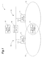
- Fig. 1 is a diagram showing the configuration of packet communication system 1.
- Packet communication system 1 according to the present embodiment is comprised of packet communication terminal (first packet communication terminal) 10, packet communication terminal (second packet communication terminal) 30, network 50 with base station 51, network 70 with base station 71, and switching center 80.
- network 50 is a network having a plurality or base stations including base station 51, and the base station 51 is connected through a link to switching center 80.
- Network 70 is a network having a plurality of base stations including base station 71, and is connected through a link to switching center 80.
- Each of base station 51 and base station 71 is wirelessly connected to packet communication terminal 10 present in the range of communication area 52 and communication area 72, and operates to transmit and receive packets to and from packet communication terminal 10.
- Switching center 80 is comprised of a router or the like and implements relaying in packet communication between packet communication terminal 30 and packet communication terminal 10.
- Packet communication terminal 10 is a mobile packet communication terminal carried by a user like the mobile communication terminals, cell phones, and so on. Packet communication terminal 10 is physically equipped with an input device such as push buttons, a display unit such as a display device, a CPU (central processing unit), a storage device such as a memory, a communication device, and so on.
- an input device such as push buttons
- a display unit such as a display device
- a CPU central processing unit
- storage device such as a memory
- communication device and so on.
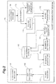
- Fig. 2 is a block diagram showing the functional configuration of packet communication terminal 10.
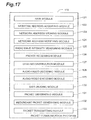
- Packer communication terminal 10 is functionally comprised of network address acquiring part (network address acquiring means) 101, network address storage (network address storing means) 102, network address notifying part (network address notifying means, ineffective network address notifying means, effective network address notifying means, and communication state notifying means) 103, radio wave intensity measuring part (radio wave intensity measuring means) 104, packet receiver (first packet receiving means) 105, data reconstruction part 106, audio-video decoder 107, audio-video encoder 108, data a dividing part 109, packet generator (first packet generating means) 110, redundant packet generator (first redundant packet generating means) 111, and packet transmitter (first packet transmitting means) 112.
- network address acquiring part network address acquiring means
- network address storage network address storage
- network address notifying part network address notifying means, ineffective network address notifying means, effective network address notifying means, and communication state notifying means
- the network address acquiring part 101 is configured as follows. Packet. communication terminal 10 detects a network to which it can be connected at its current location. Then the network address acquiring part 101 acquires a network address assigned by the detected network and makes the network address storage 102 store the network address. For example, in the case where packet communication terminal 10 is located in communication area 52 of base station 51, it acquires a network address assigned to the packet communication terminal 10 by network 50. When packet communication terminal 10 further moves from this location to a location where it is included in both communication area 52 of base station 51 and communication area 72 of base station 71, the network address acquiring part 101 further acquires another network address from network 70.
- Network address storage 102 is a storage part constructed on a memory for memorizing network addresses acquired by network address acquiring part 101.
- network address storage 102 may be a database constructed on a hard disk.
- Network address notifying part 103 notifies correspondent packet communication terminal 30 of a network address acquired by the network address acquiring part 101. For example, in the case where packet communication terminal 10 is located in communication area 52 of base station 51, it notifies packet communication terminal 30 of a network address acquired from network 50 by network address acquiring part 101. When pocket communication terminal 10 further moves from this location to a location where it is included in both communication area 52 of base station 51 and communication area 72 of base station 71, the network address notifying part 103 further notifies packet communication terminal 30 of a network address acquired from network 70 by network address acquiring part 101.
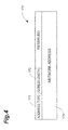
- Fig. 3 shows the configuration of packet 150 used in packet communication according to the present embodiment.
- Fig. 3 shows the configuration of packet 150 consisting of the header of the transport layer, which was newly designed by Inventors of the present invention so as to suit the use in packet communication according to the present embodiment, and data part.
- the header of the transport layer will be called an "MMSP header.”
- the MMSP header is provided with various fields such as source port number field 151, destination port number field 152, flag field 160, and so on.
- the source port number field 151 and destination port number field 152 are provided for storage of a port number indicating a type of an application protocol. Namely, a numeral indicating a type of an application protocol for the packet communication according to the present embodiment is stored in those fields.
- Flag field 160 consists of DATA field 161, FEC field 162, GOOD_ADDRESS field 163, ADD_ADDRESS field 164, and DELETE_ADDRESS field 165.
- the data part 170 subsequent to this MMSP field is provided for storage of data to be transmitted in the form of packets.
- the network address notifying part 103 For notifying correspondent packet communication terminal 30 of a network address acquired by network address acquiring part 101, as described above, the network address notifying part 103 puts "1" in ADD_ADDRESS field 164 of the MMSP header. Then the network address notifying part 103 stores data of the format shown in Fig. 4, into data part 170. Fig. 4 shows the data to be stored in data part 170 used in the notification of the network address to the packet communication terminal 30. On the occasion of the aforementioned notification of the network address, as shown in Fig. 4, network address notifying part 103 puts a type of an address in address type field 171. For example, a numeral indicating a network address of IPv4 or IPv6 is stored in address type field 171.
- a numeral indicating a length of the network address notified of is stored in address length field 172.
- address length field 172 For example, "32" indicating the address length of 32 bits in the case of IPv4 or "128" indicating the address length of 128 bits in the case of IPv6 is stored in address length field 172.
- the network address associated with the aforementioned notification is stored in network address field 173.
- the network address notifying part 103 For notifying packet communication terminal 30 of the network address acquired by the network address acquiring part 101, the network address notifying part 103 generates a packet of the configuration as described above, and transmits the packet to packet communication terminal 30.
- the network address notifying part 103 puts a network address acquired from the network, in the form of the data of structure shown in Fig. 4, into data part 170 of packet 150, puts "1" in DELETE_ADDRESS field 165 of the MMSP header, and sends the packet to packet communication terminal 30. Packet communication terminal 10 deletes this network address from network address storage 102.
- the network address notifying part 103 also performs the following processing on the basis of an instruction from radio wave intensity measuring part 104.
- the radio wave intensity measuring part 104 measures intensities of radio waves from respective networks to which packet communication terminal 10 is connected.
- the radio wave intensity measuring part 104 is configured so that when a maximum intensity out of a plurality of intensities measured is not less than a predetermined threshold (first predetermined threshold), it detects a network including a base station having transmitted the radio wave of the maximum intensity. Then it outputs a network address acquired from the detected network and stored in network address storage 102, to network address notifying part 103.
- network address notifying part 103 puts "1" into GOOD_ADDRESS field 163 of the MMSP header, and sends packet 150 with data part 170 storing data consisting of the network address from the radio wave intensity measuring part 104, to packet communicat ion terminal 30.
- the radio wave intensity measuring part 104 controls packet transmitter 112 so as to send packets to only the network including the base station having transmitted the radio wave of the maximum intensity.
- the radio wave intensity measuring part 104 When all the intensities of the radio waves measured are smaller than a predetermined threshold (second predetermined threshold), the radio wave intensity measuring part 104 outputs this fact to network address notifying part 103. Receiving this output, network address notifying part 103 puts "1" in GOOD_ADDRESS field 163 of the MMSP header, and sends packet 150 of structure with no designated network address in data part 170 to packet communication terminal 30. In this case, the radio wave intensity measuring part 104 controls packet transmitter 112 so as to send packets generated from data to be transmitted to the packet communication terminal 30, to all the networks to which packet communication terminal 10 is connected.
- the two predetermined thresholds (the first predetermined threshold and the second predetermined threshold) used by radio wave intensity measuring part 104 may be identical to each other, or may be different values.
- Packet receiver 105 receives a packet transmitted from packet communication terminal 30. When a plurality of network addresses are stored in network address storage 102, the packet receiver 105 receives all packets transmitted to these network addresses, as packets addressed to the packet communication terminal 10.
- Data reconstruction part 106 reconstructs data from the packets received by packet receiver 105.
- Audio-video decoder 107 decodes the data reconstructed by data reconstruction part 106, into audio and/or video data.
- Audio-video encoder 108 encodes audio and/or video data to be transmitted from packet communication terminal 10 to packet communication terminal 30, to generate encoded data.
- Data dividing part 109 divides this encoded data into divisional data, for packetizing the data generated by audio-video encoder 108.
- Packet generator 110 adds an MMSP header to each of the above divisional data to generate packets. At this time, packet generator 110 puts "1" in DATA field 161 of the MMSP header to indicate that this packet is constructed from data.
- Redundant packet generator 111 generates redundant data by forward error correction codes from the above divisional data and adds an MMSP header to each of the redundant data to generate redundant packets. At this time, redundant packet generator 111 puts "1" in FEC field 162 of the MMSP header, thereby indicating that this packet contains redundant data by 5 forward error correction codes.
- the redundant packet generator 111 generates redundant packets by the number according to the number of networks to which packet communication terminal 10 is connected. For example, when packet communication terminal 10 is connecced to two networks, it generates K redundant packets, corresponding to the number of divisional data, K.
- the packet communication terminal 10 distributes and transmits the redundant packets generated in this way, and the packets generated by the packet generator 110, to the two networks, and the packet communication terminal 30 can reconstruct the data by receiving either the K packets or redundant packets out of these packets and redundant packets.
- packet communication terminal 10 sends the packets to only the network including the base station having transmitted the radio wave, as described above; in this case, therefore, redundant packet generator 111 generates no redundant packet.
- Packet transmitter 112 further adds an IP header to each of the packets generated by packet generator 110 and to each of the redundant packets generated by the redundant packet generator 111. Then the packet transmitter 112 transmits the packets each with the IP header to packet communication terminal 30. In this transmission, where packet transmitter 112 is controlled by radio wave intensity measuring part 104 so as to send packets to the network including the base station having transmitted the radio wave of the maximum intensity as described above, it sends the packets generated by the packet (generator 110, to only the relevant network.
- packet transmitter 112 is controlled so as to send the packets to all the networks to which the packet communication terminal 10 is connected, by an instruction from radio wave intensity measuring part 104; in that case, packet transmitter 112 distributes and transmits the packets and redundant packets each with the IP header as described above, to the networks to which the packet communication terminal 10 is connected. On the occasion of this distribution, packet transmitter 112 transmits the packets while storing network addresses acquired from the respective networks, as source addresses of the IP header, according to the networks to which the above packets and redundant packets are to be transmitted.
- audio-video encoder 108 encodes audio data, video data, or the like to generate data 201 to be transmitted to packet communication terminal 30.
- This process (reference numeral 200) is a process executed in the application layer level.
- data divider 109 divides data 201 to generate a plurality of divisional data 211-214.
- redundant packet generator 111 generates redundant data 215-218 by forward error correction codes from the divisional data 211-214.
- packet generator 110 and redundant packet generator 111 add MMSP headers 221-228 to divisional data 211-214 and to redundant data 215-218, respectively.
- the processes (reference numeral 210) shown in Figs. 5B, 5C, and 5D are processes each executed in the transport layer level. Thereafter, as shown in Fig.
- packet transmitter 112 adds IP headers 241-248 to the respective packets with the MMSP headers and then sends these packets with the IP headers to networks.
- This process (reference numeral 240) shown in Fig. 5E is a process executed in the network layer level.
- Packet communication terminal 30 is a packet communication terminal capable of performing packet communication like the personal computers.
- the packet communication terminal 30, different from packet communication terminal 10 is not based on the premise of migration and is connected to one network.
- the packet communication terminal 30 can also be a mobile packet communication terminal like the mobile communication terminals and others if it is comprised of the after-described components of packet communication terminal 30 and the aforementioned functional components of packet communication terminal 10.
- the packet communication terminal 30 is physically comprised of a CPU (central processing unit), a storage device such as a memory, a storage device such as a hard disk, an input device such as a keyboard and a mouse, a display device such as a display unit, a communication device, and so on.
- a CPU central processing unit
- storage device such as a memory
- storage device such as a hard disk
- an input device such as a keyboard and a mouse
- a display device such as a display unit
- a communication device and so on.
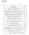
- Fig. 6 is a block diagram showing the functional configuration of packet communication terminal 30.
- the packet communication terminal 30, as shown in Fig. 6, is functionally comprised of packet receiver (second packet receiving means) 301, received packet discrimination processor 302, destination network address storage (destination network address storing means) 303, data reconstruction part 304, audio-video decoder 305, audio-video encoder 306, data divider 307, packet generator (second packet generating means) 308, redundant packet generator (second redundant packet generating means) 309, and packet transmitter (second packet transmitting means) 310.
- packet receiver second packet receiving means
- received packet discrimination processor 302 destination network address storage (destination network address storing means) 303
- data reconstruction part 304 data reconstruction part 304
- audio-video decoder 305 audio-video encoder
- audio-video encoder 306 audio-video encoder
- data divider 307 packet generator (second packet generating means) 308, redundant packet generator (second redundant packet generating means) 309
- packet transmitter second packet transmitting means
- Packet receiver 301 receives a packet transmitted from correspondent packet communication terminal 10 and outputs it to received packet discrimination processor 302.
- Received packet discrimination processor 302 receives the packet from packet receiver 301. Then it performs the following processing with reference to flag field 160 in the MMSP header of this packet. When “1" is stored in DATA field 161 of the flag field 160, received packet discrimination processor 302 determines that this packet constitutes part of data transmitted from packet communication terminal 10, and outputs this packet to data reconstruction part 304. When “1" is stored in FEC field 162, received packet discrimination processor 302 determines that this packet is one generated from redundant data, and outputs this packet to data reconstruction part 304. When “1” is stored with reference to GOOD_ADDRESS field 163, received packet discrimination processor 302 refers to data part 170 and determines whether a network address is stored in its network address field 173.
- received packet discrimination processor 302 controls packet transmitter 310 so as to transmit packets to only the stored network address.
- received packet discrimination processor 302 controls packet transmitter 310 so as to transmit pockets to a plurality of destination network addresses stored in destination network address storage 303.
- ADD_ADDRESS field 164 received packet discrimination processor 302 makes destination network address storage 303 store a network address Stored in network address field 173 of data part 170, as a destination network address.
- received packer discrimination processor 302 deletes a destination network address equivalent to a network address, stored in network address field 173 of data part 170, from destination network address storage 303.
- Destination network address storage 303 stores a network address notified of by packet communication terminal 10, as a destination network address.
- Destination network address storage 303 may memorize a list of destination network addresses on a memory or may memorize a list of destination network addresses while constructing a database on a hard disk, for example.
- the data reconstruction part 304, audio-video decoder 305, audio-video encoder 306, data divider 307, and packet generator 308 have the same functions as those of the data reconstruction part 106, audio-video decoder 107, audio-video encoder 108, data divider 109, and packet generator 110 of the packet communication terminal 10, respectively.
- redundant packer generator 309 In order to transmit packets to a plurality of destination network addresses stored in destination network address storage 303, redundant packer generator 309 generates redundant data by forward error correction codes from divisional data generated through division of data by data divider 307, and adds the MMSP headers to the redundant data to generate packets. At this time, redundant packet generator 309 puts "1" in the FEC field 162 of the MMSP header of each packet, thereby indicating that this packet contains redundant data by forward error correction codes.
- the redundant packet generator 111 generates redundant packets by the number according to the number of destination, network addresses. For example, in the case where packet communication terminal 30 transmits packets to two destination network addresses, it generates K redundant packets, corresponding to the number of divisional data, K.
- the packet communication terminal 30 distributes and transmits the redundant packets generated in this way and the packets generated by packet generator 308, to the two destination network addresses, whereby packet communication terminal 10 becomes able to reconstruct the data by receiving either the K packets or redundant packets out of these packets and redundant packets.
- the packet communication terminal 30 receives from packet communication terminal 10 a packet in which "1" is stored in GOOD_ADDRESS field 163 and in which a network address is designated in network address field 173 of data part 170 and where received packet discrimination processor 302 controls packet transmitter 310 so as to transmit packets to only this network address, as described above, the redundant packet generator 309 generates no redundant packet.
- Packet transmitter 310 transmits a packet to a destination network address stored in destination network address storage 303.
- packet communication terminal 30 receives from packet communication terminal 10 a packet in which "1" is stored in GOOD_ADDRESS field 163 and in which a network address is designated in network address field 173 of data part 170 and where received packet discrimination processor 302 controls packet transmitter 310 so as to transmit packets to only this network address, this transmission is carried out so that packet transmitter 310 transmits packets generated by packet generator 308, to only the network address.
- packet communication terminal 30 receives from packet communication terminal 10 a packet in which "1" is stored in GOOD_ADDRESS field 163 and in which no network address is designated in network address field 173 of data part 170 and where the received packet discrimination processor 302 controls packet transmitter 310 so as to transmit packets to a plurality of destination network addresses stored in destination network address storage 303, packet transmitter 310 distributes and transmits the packets generated by packet generator 308 and the redundant packets generated by redundant packet generator 309, to the plurality of destination network addresses.
- packet communication system 1 The operation of packet communication system 1 according to the present embodiment will be described below, together with the packet communication method according to the present embodiment.
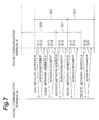
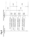
- First described with reference to the sequence diagrams of Fig. 7 and Fig. 8 is the processing about the notification of network addresses from packet communication terminal 10 to packet communication terminal 30 carried out in conjunction with soft handover to switch between connected base stations because of migration of packet communication terminal 10 from communication area 52 of base station 51 in network 50 to communication area 72 of base station 71 in network 70.
- Fig. 7 shows the processing associated with the soft handover in the case where packet communication terminal 10 receives weak radio waves from the both base stations in the boundary overlapping region of the communication areas of base station 51 in network 50 and base station 71 in network 70.
- packet communication terminal 10 is first in a state in which it is present at a location where it can receive the radio wave of high intensity from network 50 and in which it has already notified packet communication terminal 30 of network address A acquired from network 50.
- a period indicated by reference numeral 500 defines a period in which packet communication terminal 10 can receive the strong radio wave from network 50. Let us suppose that packet communication terminal 10 then moves to a location where it can receive the radio waves from both network 50 and network 70. At this times packet communication terminal 10 acquires network address B from network 70.
- ADD_ADDRESS field 164 of the MMSP header puts "1" in ADD_ADDRESS field 164 of the MMSP header and puts the network address B in network address field 173 of data part 170 to generate a packet, and thereafter it sends the packet as an ADD_ADDRESS message to packer communication terminal 30 (step S11).
- a period denoted by reference numeral 502 indicates a period in which packet communication terminal 10 receives the weak radio wave from network 70.
- Packet communication terminal 10 receives an acknowledgment message from packet communication terminel 30 in response to this ADD_ADDRESS message (step S12). This completes the processing about the notification of network address B.
- packet communication terminal 10 Since packet communication terminal 10 is able to receive the strong radio wave from network 50, it then puts "1" in GOOD_ADDRESS field 163 of the MMSP header and puts network address A acquired from network 50, in network address field 173 of data part 170 to generate a GOOD_ADDRESS message, and transmits it to packet communication terminal 30 (step S13). Packet communication terminal 10 receives an acknowledgment message from packet communication terminal 30 in response to this GOOD_ADDRESS message (step S14). After receiving this GOOD_ADDRESS message, packet communication terminal 30 comes to transmit packets to only the network address A.
- packet communication terminal 10 further moves to a location where it can receive weak radio waves from both networks 50 and 70. Namely, it migrates into a border region between the two networks.
- a period denoted by reference numeral 501 indicates a period in which packet communication terminal 10 receives the weak radio wave from network 50. Since there is no network from that packet communication terminal 10 at this location can receive a strong radio wave, it sends a GOOD_ADDRESS message wherein "1" is stored in GOOD_ADDRESS field 163 of the MMSP header and wherein no network address is designated in network address field 173 of data part 170, to packet communication terminal 30 (step S15). Packet communication terminal 10 receives an acknowledgment message from packet communication terminal 30 having received this GOOD_ADDRESS message (step S16). After these processes at steps S15 and S16, packet communication terminal 30 comes to transmit packets to both network addresses A and B.
- packet communication terminal 10 further moves to a location where it can receive a strong radio wave from network 70.
- a period denoted by reference numeral 503 indicates a period in which packet communication terminal 10 can receive the strong radio wave from network 70.
- Packet communication terminal 10 having moved to this location transmits a GOOD_ADDRESS message with the network address B designated, to packet communication terminal 30 (step S17).
- Packet communication terminal 10 receives an acknowledgment message from packet communication terminal 30 in response to this GOOD_ADDRESS message (step S18). After these processes at steps S17 and S18, the packet communication terminal 30 comes to transmit packets to only network address B.
- packet communication terminal 10 is assumed to move to a location where it can receive no radio wave from network 50 and receive the strong radio wave from only network 70.
- the packet communication terminal 10 having moved to this location sends a DELETE_ADDRESS message wherein "1" is stored in DELETE_ADDRESS field 165 of the MMSP header and wherein network address A is stored in network address field 173 of data part 170, to packet communication terminal 30 (step S19).
- Packet communication terminal 10 receives an acknowledgment message from packet communication terminal 30 in response to this DELETE_ADDRESS message (step S20).
- Fig. 8 shows processing associated with soft handover in the case where the boundary overlapping region of the communication areas of base station 51 in network 50 and base station 71 in network 70 includes a region where packet communication terminal 10 can receive strong radio waves from the both base stations.
- packet communication terminal 10 is located in the communication area of base station 51 in network 50 and can receive the strong radio wave from network 50, as shown in Fig. 8.
- packet communication terminal 10 has already notified packet communication terminal 30 of the network address A acquired from network 50.
- a period denoted by reference numeral 505 indicates a period in which packet communication terminal 10 can receive the strong radio wave from network 50.
- packet communication terminal 10 When packet communication terminal 10 further moves to a location where it can also receive a weak radio wave from base station 71 in network 70, it acquires a network address from network 70.
- a period denoted by reference numeral 507 is a period in which packet communication terminal 10 can receive the weak radio wave from network 70.
- packet communication germinal 10 transmits an ADD_ADDRESS message containing the acquired network address B, to packet communication terminal 30 (step 321).
- Packet communication terminal 10 receives an acknowledgment message from packet communication terminal 30 in response to this ADD_ADDRESS message (step S22). Through these processes at steps S21 and S22, packet communication terminal 30 comes to transmit packets to the network addresses A and B.
- packet communication terminal 10 Since packet communication terminal 10 can receive the radio wave of intensity being maximum and not less than the predetermined threshold from base station 51 in network 50, it then transmits a GOOD_ADDRESS message containing the network address A, to packet communication terminal 30 (step S23). Packet communication terminal 10 receives an acknowledgment message from packet communication terminal 30 in response to this GOOD_ADDRESS message (step S24). Through these processes at steps S23 and S24, packet communication terminal 30 comes to transmit packets to only the network address A.
- packet communication terminal 10 moves to a location where it can also receive a strong radio wave from base station 71 in network 70.
- packet communication terminal 10 transmits a GOOD_ADDRESS message, containing the network address B, to packet communication terminal 30 (step S25).
- Packet communication terminal 10 receives an acknowledgment message from packet communication terminal 30 in response to this GOOD_ADDRESS message (step S26).
- a period denoted by reference numeral 508 indicates a period in which packet communication terminal 10 can receive the strong radio wave from base station 71 in network 70.
- packet communication terminal 10 moves to a location where it can receive a weak radio wave from base station 51 in network 50 and further moves to a location where it can receive no radio wave from base station 51.
- packet communication terminal 10 transmits a DELETE_ADDRESS message containing the network address A, to packet communication terminal 30 (step S27).
- Packet communication terminal 10 receives an acknowledgment message from packet communication terminal 30 in response to this DELETE_ADDRESS message (step S28).
- packet communication terminal 30 deletes the destination network address equivalent to the network address A, which has been stored in destination network address storage 303.
- a period denoted by reference numeral 506 indicates a period in which packet communication terminal 10 can receive the weak radio wave from base station 51.
- Fig. 9 is a flowchart of processing about the notification of the network address from packet communication terminal 10 to packet communication terminal 30.
- packet communication terminal 10 first receives a radio wave from a new base station (step S101). Then packet communication terminal 10 sends a network address request message, for acquiring a network address from a network including this new base station (step S102). Packet communication terminal 10 acquires a network address assigned by the network in response to this network address request message (step S103).
- packet communication terminal 10 determines whether the acquired network address is one previously stored in network address storage 102 (step S104). When the result of this determination is that the above network address is one previously stored in network address storage 102, packet communication terminal 10 terminates this processing. On the other hand, when the above network address is absent in network address srorage 102, this network address is stored into network address storage 102 (step S105). Then network address notifying part 1C3 of packet communication terminal 10 sends an ADD_ADDRESS message containing the above network address, to packet communication terminal 30 (step S106). Network address notifying part 103 then determines whether it can receive an acknowledgment message sent in response to this ADD_ADDRESS message from packet communication terminal 30, within a set time (step S107).
- network address notifying part 103 again sends the ADD_ADDRESS message (step S106).
- the notification process of the network address is terminated.
- Fig. 10 is a flowchart showing the notification process of the DELETE_ADDRESS message.
- packet communication terminal 10 first measures a radio wave from a base station (stop S111). Based on this measurement, packet communication terminal 10 determines whether it is with in the reach of the radio wave from the base station (step S112).
- packet communication terminal 10 again performs the measurement of the radio wave from the base station (step S111).
- a network address acquired from a network including the base station is deleted from network address storage 102 (step S113).
- network address notifying part 103 sends a DELETE_ADDRESS message containing the above network address, to packet communication terminal 30 (step S114).
- Network address notifying part 103 determines whether it can receive an acknowledgment message sent in response to this DELETE_ADDRESS message from packet communication terminal 30, within a set time (step S115).
- network address notifying part 103 again sends the DELETE_ADDRESS message (step S114).
- the deletion process of the network address is terminated.
- Fig. 11 is a flowchart showing the notification process of the GOOD_ADDRESS message.
- radio wave intensity measuring part 104 of packet communication terminal 10 measures intensities of radio waves from respective base stations in respective networks to which packet communication terminal 10 is connected (step S121).
- Radio wave intensity measuring part 104 determines whether there is it radio wave with an intensity of not less than the predetermined threshold, among the intensities of the radio waves thus measured (step S122).
- network address notifying part 103 sends a GOOD_ADDRESS message containing a network address acquired from a network including a base station having transmitted the radio wave of the maximum intensity among them, to packet communication terminal 30 (step S123).
- Network address notifying part 103 determines whether an acknowledgment message to be transmitted in response to this GOOD_ADDRESS message from packet communication terminal 30 can be received within a set time (step S124). When the result of this determination is that the acknowledgment message from packet communication terminal 30 was not received within the set time, network address notifying part 103 again transmits the above GOOD_ADDRESS message (step S123).
- step S122 when there is no radio wave with an intensity of not less than the predetermined threshold, network address notifying port 103 sends a GOOD_ADDRESS message with no designated network address to packet commuication terminal 30 (step S125).
- Network address notifying part 103 determines whether an acknowledgment message to be transmitted in response to this GOOD_ADDRESS message from packet communication terminal 30 can be received within a set time (step S126). When the result of this determination is that the acknowledgment message from packet communication terminal 30 was not received within the set time, network address notifying part 103 again sends the above GOOD_ADDRESS message (step S125). On the other hand, when the acknowledgment message from packet communication terminal 30 is received within the set time, this processing is terminated.
- Fig. 12 is a flowchart of the processing executed by packet communication terminal 30 in accordance with the received ADD_ADDRESS message.
- packet, receiver 301 of packet communication terminal 30 receives the ADD_ADDRESS message from the packet communication terminal (step S131).
- received packet discrimination processor 302 determines whether the network address in the ADD_ADDRESS message received by packet receiver 301 is one previously stored in destination network address storage 303 (step S132).
- received packet discrimination processor 302 makes destination network address storage 303 store this network address as a destination network address (step S133).
- the above network address is one previously stored in destination network address storage 303, no new storage process is carried out, because this network address is already present in destination network address storage 303.
- received packet discrimination processor 302 sends an acknowledgment message to packet communication terminal 10 (step S134).
- Fig. 13 is a flowchart of the processing carried out by packet communication terminal 30 in response to the received DELETE_ADDRESS message
- packet receiver 301 of packet communication terminal 30 receives the DELETE_ADDRESS message sent from packet communication terminal 10 (stop S141).
- Received packet discrimination processor 302 determines whether a network address in this DELETE_ADDRESS message is one stored as a destination network address in destination network address storage 303 (step S142).
- this destination network address is deleted from destination network address storage 303 (step S143).
- the process of deleting the destination network address is not carried out.
- received packet discrimination processor 302 sends an acknowledgment message to packet communication terminal 10 (step S144).
- Fig. 14 is a flowchart of the processing carried out by packet communication terminal 30 in response to the received GOOD_ADDRESS message.
- packet receiver 301 of packet communication terminal 30 receives the GOOD_ADDRESS message sent from packet communication terminal 10 (step S151).
- Received packet discrimination processor 302 determines whether a network address in this GOOD_ADDRESS message is one previously stored as a destination network address in destination network address storage 303 (step S152).
- received packet discrimination processor 302 controls packet transmitter 310 so as to transmit packets to only this destination network address (step S153).
- received packet discrimination processor 302 determines whether the address type and address length of the above GOOD_ADDRESS message are "0" (step S154).
- received packet discrimination processor 302 controls packet transmitter 310 so as to transmit packets to all the destination network addresses stored in destination network address storage 303 (step S155).
- the message is judged as an abnormal message and the processing is terminated.
- received packet discrimination processor 302 sends an acknowledgment message to packet communication terminal 10 (step S156).
- Fig. 15 is a flowchart of the processing for packet communication terminal 30 to transmit packets generated from data and for packet communication terminal 10 to reconstruct the data.
- data divider 307 divides data encoded by audio-video encoder 306 of packet communication terminal 30, to generate divisional data (step S161). It is then determined whether packet transmitter 310 is controlled to transmit packets to only one destination network address (step S162). When the result of this determination is that packet transmitter 310 is controlled to transmit packets to only one destination network address, packet generator 308 adds the MMSP header to each of the above divisional data to generate packets (step S163).
- packet transmitter 310 adds the IP header to each of the packets generated by packet generator 308, puts the above destination network address in the IP header, and sends the packets to the destination network address (step S164) .
- redundant packet generator 309 first generates redundant data from the above divisional data (step S165). Then packet generator 308 generates packets with the MMSP headers added to the above divisional data and redundant packet generator 309 generates packets with the MMSP headers added to the redundant data (step S166).
- packet transmitter 310 For distributing and transmitting the above packets to the plurality of destination network addresses stored in the destination network address storage 303, packet transmitter 310 further adds the IP header to each packet, and distributes and stores these destination network addresses into the IP headers of the respective packets. Packet transmitter 310 transmits each packet to the destination network address stored in the IP header of each packet (step S167). Packet receiver 105 of packet communication terminal 10 receives packets transmitted in this way from packet communication terminal 30 (step S168). Data reconstruction part 106 reconstructs the data from the packets received by packet receiver 105 and thereafter audio-video decoder 107 decodes the data (step S169).
- Fig. 16 is a flowchart of the processing for packet communication terminal 10 to transmit packets generated from data and for packet communication terminal 30 to reconstruct the data.
- data divider 109 divides data encoded by audio-video encoder 108 of packet communication terminal 10 to generate divisional data (step S171). It is then determined whether packet transmitter 112 is controlled so as to send packets to only one network (step S172). When the result of this determination is that packet transmitter 112 is controlled to transmit packets to only one network, packet generator 110 adds the MMSP header to each of the above divisional data to generate packets (step S173).
- packet transmitter 112 For transmitting the packets to the above network, packet transmitter 112 then adds the IP header to each packet generated by packet generator 110, and puts the network address acquired from the above network, as a source network address into each IP header. Packet transmitter 112 transmits the packets thus generated, to the above network (step S174).
- redundant packet generator 111 first generates redundant data from the above divisional data (step S175). Then packet generator 110 generates packets with the MMSP headers added to the above divisional data, and redundant packet generater 111 generates packets with the MMSP headers added to the redundant data (step S176).
- packet transmitter 112 For distributing and transmitting the above packets to the plurality of networks to which packet communication terminal 10 is connected, packet transmitter 112 then further adds the IP header to each packet, and distributes and stores a plurality of network addresses stored in network address storage 102, into the IP headers of the respective packets. Packet transmitter 112 sends each packet to a network whose network address stored in the IP header whereof was acquired (stop S177). Packet receiver 301 of packet communication terminal 30 receives packets sent in this way from packet communication terminal 10 (step S178). When received packet discrimination processor 302 determines that "1'' is stored in DATA field 161 of the MMSP header of each packet received by packer receiver 301, the packet is delivered to data a reconstruction part 304. Then the data reconstruction part 304 reconstructs the data and thereafter audio-video decoder 305 decodes the data (step S179).
- packet communication program 120 for letting a packet communication terminal function as the aforementioned packet communication terminal 10.
- Fig. 17 shows the module configuration of packet communication program 120.
- packet communication program 120 comprises main module 121 in charge of processing, network address acquiring module 122, network address storing module 123, network address notifying module 124, radio wave intensity measuring module 125, packet receiving module 126, data reconstruction module 127, audio-video decoding module 128, audio-video encoding module 129, data dividing module 130, packet generating module 131, redundant packet generating module 132, and packet transmitting module 133.
- the functions of letting the packet communication terminal substantialize the operations of network address acquiring module 122, network address storing module 123, network address notifying module 124, radio wave intensity measuring module 125, packet receiving module 126, data reconstruction module 127, audio-video decoding module 128, audio-video encoding module 129, data dividing module 130, packet generating module 131, redundant packet generating module 132, and packet transmitting module 133 are similar to the respective functions of network address acquiring part 101, network address storage 102, network address notifying part 103, radio wave intensity measuring part 104, packet receiver 105, data reconstruction part 106, audio-video decoder 107, audio-video encoder 108, data divider 109, packet generator 110, redundant packet generator 111, and packet transmitter 112.
- packet communication program 320 for letting a packet communication terminal function as the aforementioned packet communication terminal 30.
- Fig. 18 shows the module configuration of packet communication program 320.
- packet communication program 320 comprises main module 321 in charge of processing, packet receiving module 322, received packet discrimination processing module 323, destination network address storing module 324, data reconstruction module 325, audio-video decoding module 326, audio-video encoding module 327, data dividing module 328, packet generating module 329, redundant packet generating module 330, and packet transmitting module 331.
- the functions of letting the packet communication terminal execute the operations of packet receiving module 322, received packet discrimination processing module 323, destination network address storing module 324, data reconstruction module 325, audio-video decoding module 326, audio-video encoding module 327, data dividing module 328, packet generating module 329, redundant packet generating module 330, and packet transmitting module 331 are similar to the respective functions of packet receiver 301, received packet discrimination processor 302, destination network address storage 303, data reconstruction part 304, audio-video decoder 305, audio-video encoder 306, data divider 307, packet generator 308, redundant packet generator 309, and packet transmitter 310.
- Packet communication program 120 and packet communication program 320 are provided, for example, by recording media such as CD-ROM, DVD, ROM, etc., or by semiconductor memories. Packet communication program 120 and packet communication program 320 may be those provided as computer data signals over a carrier wave through a network.
- packet communication system 1 when packet communication terminal 10 is present at the location where communication areas of two or more networks overlap each other, and is connectible to each of the networks, network address acquiring part 101 acquires network addresses from the respective networks.
- Network address storage 102 stores these network addresses and network address notifying part 103 notifies packet communication terminal 30 of these network addresses.
- destination network address storage 303 stores the network addresses thus notified of, as respective destination network addresses. Then packet transmitter 310 of packet communication terminal 30 distributes and transmits packets generated by packet generator 308 and packers generated by redundant packet generator 309, to the destination network addresses stored in destination network address storage 303.
- Packet receiver 105 of packet communication terminal 10 receives packets transmitted to the respective destination network addresses in this way.
- packet communication terminal 30 transmits packets to the network addresses acquired from the respective networks, even if packet communication terminal 10 further moves into a state where packet communication terminal 10 is no longer able to stay connected to any one of the networks, it can receive packets transmitted through the other networks from packet communication terminal 30, without delay.
- the packets transmitted from packet communication terminal 30 to packet communication cerminal 10 encompass packets consisting of divisional data generated from data to be transmitted, and packets consisting of redundant data generated by forward error correction codes from the divisional data.
- Packet transmitter 310 distributes and transmits these packets to the destination network addresses notified of by packet communication terminal 10. This distribution is implemented in such a manner that even if any one of the destination network addresses becomes ineffective, packet communication terminal 10 can receive different packets in the number equal to or greater than the number of packets generated by packet generator 308. Therefore, packet communication terminal 10 can receive packets in the number permitting recovery of the above data. As a result, packet communication terminal 10 can receive the packets transmitted from packet communication terminal 30, without delay.
- network address notifying part 103 sends a DELETE_ADDRESS message containing a network address acquired from a network to which packet communication terminal 10 is no longer able to stay connected, to packet communication terminal 30.
- Received packet discrimination processor 302 of packet communication terminal 30 disables a destination network address corresponding to the network address included in the above DELETE_ADDRESS message. Namely, it deletes the above destination network address stored in destination network address storage 303. Therefore, it is feasible to cut down the wasto that packet communication terminal 30 transmits packets to a network to which packet communication terminal 10 is unable to stay connected.
- radio wave intensity measuring part 104 measures intensities of radio waves from the respective networks.
- network address notifying part 103 sends a GOOD_ADDRESS message containing a network address acquired from the network having transmitted the radio wave of the maximum intensity, to packet communication terminal 30.
- packet transmitter 310 transmits packets to a destination network address corresponding to the network address included in this GOOD_ADDRESS message.
- packet communication terminal 10 in the network transmitting the radio wave of the intensity being not less than the predetermined threshold and being maximum among the plurality of networks, it can be assumed that packet communication terminal 10 is located near a base station belonging to the network and is in a good communication state therewith, and, under a judgment that packet communication terminal 10 is able to stay connected to the network while maintaining this communication state for the time being, packet communication terminal 30 determines the above network address notified of, as a destination network address and sends packets to this destination network address. Therefore, packet communication terminal 10 can receive packets transmitted from packet communication terminal 30, without delay and it is feasible to cut down the waste of transmitting packets through all the networks to which packet communication terminal 10 can be connected.
- network address notifying part 103 sends a GOOD_ADDRESS message containing no designated network address, to packet communication terminal 30.
- Packet communication terminal 30 acknowledges that no network address is designated in the GOOD_ADDRESS message, and then transmits packets to each of the plurality of destination network addresses stored in destination network address storage 303.
- the packet communication terminal 10 when the intensities of the radio waves from the respective networks measured by radio wave intensity measuring part 104 are smaller than the predetermined threshold, the packet communication terminal 10 is determined to be located in a border region among the communication areas of the respective networks, and packet communication terminal 30 transmits packets to the network addresses acquired from the respective networks by packet communication terminal 10, as destination network addresses. In this configuration, even if packet communication terminal 10 moves from the boundary region of the networks into a state where it is no longer able to stay connected to any one of the networks, packet communication terminal 10 can receive packets through the other networks from packet communication terminal 30, without delay.
- network address notifying part 103 transmits network addresses acquired from the respective networks, to packet communication terminal 30.
- Destination network address storage 303 of packet communication terminal 30 stores the network addresses transmitted from packet communication terminal 10, as respective destination network addresses.
- packet transmitter 112 of packet communication terminal 10 distributes and transmits packets generated by packet generator 110 and packets generated by redundant packet generator 111, to the networks to which packet communication terminal 10 can be connected.
- Packet receiver 301 of packet communication terminal 30 receives packets transmitted through the respective networks from packet communication terminal 10.
- packet communication terminal 10 distributes and transmits packets to the connectible networks as described above; whereby, even if packet communication terminal 10 further moves into a state where it is no longer able to stay connected to any one of the networks, the packets transmitted from packet communication terminal 10 can be received through the other networks by packet communication terminal 30, without delay.
- the packets transmitted from packet communication terminal 10 to packet communication terminal 30 encompass packets consisting of divisional data generated from data to be transmitted, and packets consisting of redundant data generated by forward error correction codes from the divisional data.
- Packet transmitter 112 distributes and transmits these packets to the plurality of networks to which packet communication terminal 10 can be connected. This distribution is implemented in such a manner that even if packet communication terminal 10 becomes no longer able to stay connected to any one of the networks, packets communication terminal 30 can receive different packets in the number equal to or greater than the number of packets generated by packet generator 110. Therefore, packet communication terminal 30 can receive packets in the number permitting recovery of the above data. As a result, packet communication terminal 30 can receive packets transmitted from packet communication terminal 10, without delay.
- the present invention can be modified in various ways without having to be limited to the above-stated embodiments.
- the packets when packets were transmitted through multiple networks, the packets were transmitted while distributing the packets with the headers added to the divisional data obtained by dividing data to be transmitted, and the packets with the headers added to the redundant data generated from the divisional data, to the networks.
- the packets with the headers added to the divisional data obtained by dividing data to be transmitted may be transmitted through all the networks to which the packet communication terminal can be connected. In this case, even if the packet communication terminal becomes no longer able to stay connected to any one of multiple networks to which the packet communication terminal is connected, the correspondent packet communication terminal can receive the packers transmitted through the other networks, without delay.
Abstract
Description
- The present invention relates to a packet communication terminal, a packet communication system, a packet communication method, and a packet communication program.
- In recent years, packet communication terminals carried by users are spreading as typified by mobile communication terminals and others. The packet communication terminals subject to movement like the mobile communication terminals migrate among communication areas established by base stations belonging to different networks. When a packet communication terminal migrates between communication areas of different networks, the packet communication terminal is assigned different network addresses in the respective networks connected before and after the migration. Mobile-IP is known as a technique of enabling the packets communication terminal assigned the different addresses before and after the migration as described, to communicate with a correspondent packet communication terminal. In Mobile-IP, a home agent (HA), which is a management node in a home network (HN) as a network to which the packet communication terminal originally belongs, and a foreign agent (FA), which is a management node in a foreign network (FN) being the other network, broadcast an agent advertisement in their network under management thereof. This agent advertisement is provided with the Life-Time field. For example, let us suppose a case where a packet communication terminal migrates from its HN to a certain FN. When the packet communication terminal fails to receive a new agent advertisement from the HN even after an elapsed time indicated in the Life-Time field of the agent advertisement received last in the HN, it acknowledges that it has moved off the HN. Then the packet communication terminal receives an agent advertisement in the staying FN, and it acknowledges that it has moved into the FN. Then the packet communication terminal proceeds to the following registration process in order to implement packet communication in the staying FN. In this registration process, first, the packet communication terminal sends a registration request to the FA. This registration request is sent with a c/o (care-of) address of the packet communication terminal in the FN from the FA to the HA. Then the HA registers the c/o address of the packet communication terminal and the network address of the packet communication terminal in correlation with each other, and then sends a registration response to the FA. This registration response is forwarded from the FA to the packet communication terminal to be received by the packet communication terminal, thus completing the registration process. Thereafter, when a packet is sent from a correspondent packet communication terminal to the network address assigned by the HA, the HA adds the c/o address to this packet, encapsulates it, and then forwards the encapsulated packet to the FA. The FA removes the c/o address from the packet and sends the packet to the packet communication terminal. Mobile-IP as described above implements the packet communication from the correspondent packet communication terminal to the migrating packet communication terminal.
- In the case where the packet communication terminal migrates from the HN to the FN, however, the migrating packet communication terminal is unable to receive a packet transmitted from the correspondent packet communication terminal during a period between a time when it has received the last agent advertisement in the network before the migration and a time of completion of the aforementioned registration process. A technique of decreasing the period in which the packet communication terminal is unable to receive any packet because of the migration is a technique of decreasing the above-described packet undelivered period by letting a base station controller perform the aforementioned registration process with the HA at a time of completion of a handover process executed on the occasion of a migration between base stations (e.g., Japanese Patent Application Laid-Open No. 2002-191066).
- However, aforementioned Mobile-IP and the technique described in Japanese Patent Application Laid-Open No. 2002-191066 have the problem that there remains not a little time of delay in the packet communication between the packet communication terminal migrating between different networks, and the correspondent packet communication terminal. As a result, there occurs delay of data recovered from packets, so as to result in interruption of communication demanding the real time property, for example, as in voice communication or the like.
- The present invention has been accomplished in order to solve the above problem and an object of the present invention is to provide a packet communication terminal, a packet communication system, a packet communication method, and a packet communication program capable of implementing delay-free packet communication with a correspondent packet communication terminal even during migration between different networks.
- In order to achieve the above object, a packet communication terminal according to the present invention is a packet communication terminal for packet communication comprising: network address acquiring means for acquiring a network address of the packet communication terminal from a network to which the packet communication terminal can be connected; network address storing means for storing the network address acquired by the network address acquiring means; network address notifying means for notifying a correspondent packet communication terminal of the network address stored in the network address storing means; and first packet receiving means for receiving a packet sent from the correspondent packet communication terminal to the network address; wherein when there exist a plurality of networks to which the packet communication terminal can be connected, the network address acquiring means acquires a plurality of aforesaid network addresses from the respective networks; wherein the network address storing means stores the plurality of network addresses; wherein the network address notifying means notifies the correspondent packet communication terminal of the plurality of network addresses; and wherein the first packet receiving means receives packets generated from identical data and sent from the correspondent packet communication terminal to the respective network addresses.
- In order to achieve the above object, a packet communication program according to the presents invention is a packet communication program for letting a packet communication terminal function as: network address acquiring means for acquiring a network address of the packet communication terminal from a network to which the packet communication terminal can be connected; network address storing means for storing the network address acquired by the network address acquiring means; network address notifying means for notifying a correspondent packet communication terminal of the network address stored in the network address storing means; and first packet receiving means for receiving a packet sent from the correspondent packet communication terminal to the network address; wherein when there exist a plurality of networks to which the packet communication terminal can be connected, the network address acquiring means acquires a plurality of aforesaid network addresses from the respective networks; wherein the network address storing means stores the plurality of network addresses; wherein the network address notifying means notifies the correspondent packet communication terminal of the plurality of network addresses; and wherein the first packet receiving means receives packets generated from identical data and sent from the correspondent packet communication terminal to the respective network addresses.
- In order to achieve the above object, a packet communication terminal according to the present invention is a packet communication terminal for packet communication comprising: destination network address storing means for storing a network address notified of by a correspondent packet communication terminal, as a destination network address; second packet generating means for generating a packet from data to be transmitted to the correspondent packet communication terminal; and second pocket transmitting means for transmitting the packet to the correspondent packet communication terminal; wherein when a plurality of aforesaid network addresses are notified of by the correspondent packet communication terminal, the destination network address storing means stores a plurality of aforesaid destination network addresses corresponding to the plurality of network addresses; and wherein when a plurality of aforesaid a destination network addresses are stored in the destination network address storing means, the second packet transmitting means transmits aforesaid packets generated from identical data, to the respective destination network addresses.
- In order to achieve the above object, a packet communication program according to the present invention is a packet communication program for letting a packet communication terminal function as: destination network address storing means for storing a network address notified of by a correspondent packet communication terminal, as a destination network address; second packet generating means for generating a packet from data to be transmitted to the correspondent packet communication terminal; and second packet transmitting means for transmitting the packet to the correspondent packet communication terminal; wherein when a plurality of aforesaid network addresses are notified of by the correspondent packet communication terminal, the destination network address storing means stores a plurality of aforesaid destination network addresses corresponding to the plurality of network addresses; and wherein when a plurality of aforesaid destination network addresses are stored in the destination network address storing means, the second packet transmitting means transmits aforesaid packets generated from identical data, to the respective destination network addresses.
- In order to achieve the above object, a packet communication system according to the present invention is a packet communication system for packet communication between, a first packet communication terminal and a second packet communication terminal, wherein the first packet communication terminal comprises: network address acquiring means for acquiring a network address of the packet communication terminal from a network to which the first packet communication terminal can be connected; network address storing means for storing the network address acquired by the network address acquiring means; network address notifying means for notifying the second packet communication terminal of the network address stored in the network address storing means; and first packet receiving means for receiving a packet sent from the second packet communication terminal to the network address; wherein the second packet communication terminal comprises: destination network address storing means for storing the network address notified of by the first packet communication terminal, as a destination network address; second packet generating means for generating a packet from data to be transmitted to the first packet communication terminal; and second packet transmitting means for transmitting the packet to the first packet communication terminal; wherein when there exist a plurality of networks to which the first packet communication terminal can be connected, the network address acquiring means of the first packet communication terminal acquires a plurality of aforesaid network addresses from the respective networks; wherein the network address storing means of the first packet communication terminal stores the plurality of network addresses; wherein the network address notifying means of the first packet communication terminal notifies the second packet communication terminal of the plurality of network addresses; wherein when a plurality of aforesaid network addresses are notified of by the first packet communication terminal, the destination network address storing means of the second packet communication terminal stores a plurality of aforesaid destination network addresses corresponding to the plurality of network addresses; wherein when a plurality of aforesaid destination network addresses are stored in the destination network address storing means, the second packet transmitting means of the second packet communication terminal transmits aforesaid packets generated from identical data, to the respective destination network addresses; and wherein the first packet receiving means of the first packet communication terminal receives the packets generated from the identical data and transmitted from the second packet communication terminal to the respective network addresses.
- In order to achieve the above object, a packet communication method according to the present invention is a packet communication method for packet communication between a first packet communication terminal and a second packet communication terminal, the packet communication method comprising: a network address acquiring step wherein network address acquiring means of the first packet communication terminal acquires a network address of the packet communication terminal from a network to which the first packet communication terminal can be connected; a network address storing step wherein network address storing means of the first packet communication terminal stores the network address acquired by the network address acquiring means; a network address notifying step wherein network address notifying means of the first packet communication terminal notifies the second packet communication terminal of the network address stored in the network address storing means; a destination network address storing step wherein destination network address storing means of the second packet communication terminal stores the network address notified of by the first packet communication terminal, as a destination network address; a first packet generating step wherein second packet generating means of the second packet communication terminal generates a packet from data to be transmitted to the first packet communication terminal; a first packet transmitting step wherein second packet transmitting means of the second packet communication terminal transmits the packet to the first packet communication terminal; and a first packet receiving step wherein first packet receiving means of the first packet communication terminal receives the packet transmitted from the second packet communication terminal to the network address; wherein in the network address acquiring step, when there exist a plurality of networks to which the first packet communication terminal can be connected, the network address acquiring means of the first packet communication terminal acquires a plurality of aforesaid network addresses from the respective networks; wherein in the network address storing stop the network address scoring means of the first packet communication terminal stores the plurality of network addresses; wherein in the network address notifying step the network address notifying means of the first packet communication terminal notifies the second packet communication terminal of the plurality of network addresses; wherein in the destination network address storing step, when a plurality of aforesaid network addresses are notified of by the first packet communication terminal, the destination network address storing means of the second packet communication terminal stores a plurality of aforesaid destination network addresses corresponding to the respective network addresses; wherein in the first packet transmitting step, when a plurality of aforesaid destination network addresses are stored in the destination network address storing means, the second packet transmitting means of the second packet communication terminal transmits aforesaid packets generated from identical data, to the respective destination network addresses; and wherein in the first packet receiving stop the first packet receiving means of the first packet communication terminal receives the packets generated from the identical data and transmitted from the second packet communication terminal to the respective destination network addresses.
- According to these aspects of the invention, when the first packet communication terminal as a migrating packet communication terminal moves, for example, to a location where communication areas of two or more networks overlap each other, and becomes connectible to each of the networks, the network address acquiring means acquires network addresses from the respective networks. The network address storing means stores these network addresses and the network address notifying means notifies the second packet communication terminal as a correspondent packet communication terminal of the network addresses. In the second packet communication terminal, the destination network address storing means stores the network addresses thus notified of, as respective destination network addresses. Then the second packet transmitting means transmits packets generated from identical data by the second packet generating means, to the respective destination network addresses stored in the destination network address storing means. In the first packet communication terminal, the first packet receiving mean receives the packets transmitted to the respective destination network addresses as described above, as packets generated from the identical data. In the case where the first packet communication terminal is present at the location where communication areas of multiple networks overlap each other and is connectible to the networks, the second packet communication terminal is made to transmit packets to the network addresses acquired from the respective networks, as described above. Even if the first packet communication terminal becomes no longer able to stay connected to any one of the networks because of further migration, it can also receive packets from the second packet communication terminal through the other networks without delay.
- In the packet communication terminal of the present invention, when a plurality of aforesaid destination network addresses are stored in the destination network address storing means, the packets transmitted to the plurality of network addresses by the second packet transmitting means may be packets identical to each other.
- In the packet communication program of the present invention, when a plurality of aforesaid destination network addresses are stored in the destination network address storing means, the packets transmitted to the plurality of network addresses by the second packet transmitting means may be packets identical to each other.
- In the packet communication system of the present invention, when a plurality of aforesaid destination network addresses are stored in the transmitted to the respective destination network addresses by the second packet transmitting means of the second packet communication terminal may be packets identical to each other.
- In the packet communication method of the present invention, in the first packet transmitting step, when a plurality of aforesaid destination network addresses are stored in the destination network address storing means, the packets transmitted to the respective destination network addresses by the second packet transmitting means of the second packet communication terminal may be packets identical to each other.
- According to these aspects of the invention, when there are a plurality of destination network addresses notified of by the first packet communication terminal and stored in the destination network address storing means, the second packet communication terminal sends identical packets to the respective destination network addresses. Therefore, even if the first packet communication terminal becomes no longer able to stay connected to any one of the networks because of migration, the first packet communication terminal can receive packets transmitted to the network addresses assigned by the other networks. As a result, the first packet communication terminal can receive packets transmitted from the second packet communication terminal, without delay.
- Preferably, the packet communication terminal of the present invention further comprises second redundant packet generating means for generating redundant packets by forward error correction codes from data part of the packets generated by the second packet generating means; and when a plurality of aforesaid destination network addresses are stored in the destination network address storing means, the second packet transmitting means distributes and transmits the packets generated by the second packet generating means and the redundant packets generated by the second redundant packet generating means, to the plurality of destination network addresses in such a manner that even in a case where any one of the destination network addresses becomes ineffective, the correspondent packet communication terminal can receive different packets in the number equal to or greater than the number of packets generated by the second packet generating means.
- Preferably, the packet communication program of the present invention lets the packet communication terminal further function as: second redundant packet generating means for generating redundant packets by forward error correction codes from data part of the packets generated by the second packet generating means; and when a plurality of aforesaid destination network addresses are stored in the destination network address storing means, the second packet transmitting means distributes and transmits the packets generated by the second packet generating means and the redundant packets generated by the second redundant packet generating means, to the plurality of destination network addresses in such a manner that even in a case where any one of the destination network addresses becomes ineffective, the correspondent packet communication terminal can receive different packets in the number equal to or greater than the number of packets generated by the second packet generating means.
- Preferably, in the packet communication system of the present invention, the second packet communication terminal further comprises second redundant packet generating means for generating redundant packets by forward error correction codes from data part of the packets generated by the second packet generating means; and when a plurality of aforesaid destination network addresses are stored in the destination network address storing means, the second packet transmitting means of the second packet communication terminal distributes and transmits the packets generated by the second packet generating means and the redundant packets generated by the second redundant packet generating means, to the plurality of destination network addresses in such a manner that even in a case where any one of the destination network addresses becomes ineffective, the first packet communication terminal can receive different packets in the number equal to or greater than the number of packets generated by the second packet generating means.
- Preferably, the packet communication method of the present invention further comprises a first redundant packet generating step wherein second redundant packet generating means of the second packet communication terminal generates redundant packets by forward error correction codes from data part of the packets generated by the second packet generating means; and in the first packet transmitting step, when a plurality of aforesaid destination network addresses are stored in the destination network address storing means, the second packet transmitting means of the second packet communication terminal distributes and transmits the packets generated by the second packet generating means and the redundant packets generated by the second redundant packet generating means, to the plurality of destination network addresses in such a manner that even in a case where any one of the destination network addresses becomes ineffective, the first packet communication terminal can receive different packets in the number equal to or greater than the number of packets generated by the second packet generating means.
- According to these aspects of the invention, the second packet communication terminal makes the second redundant packet generating means generate redundant packets by forward error correction codes from data part of packets. Then the second packet transmitting means distributes and transmits the redundant packets and the packets generated by the second packet generating means, to the respective destination network addresses. This distribution is effected in such a manner that even if any one of the above destination network addresses becomes ineffective, the first packet communication terminal can receive different packets in the number equal to or greater than the number of packets generated by the second packet generating means. Therefore, the first packet communication terminal can receive the packets in the number that permits recovery of the above data. As a result, the first packet communication terminal can receive packets transmitted from the second packet communication terminal, without delay.
- Preferably, the packet communication terminal of the present invention further comprises ineffective network address notifying means for notifying the correspondent packet communication terminal of the network address acquired by the network address acquiring means from the network to which the packet communication terminal is no longer able to stay connected, and information that the network address is made ineffective.
- Preferably, the packet communication program of the present invention lots the packet communication terminal further function as: ineffective network address notifying means for notifying the correspondent packet communication terminal of the network address acquired by the network address acquiring means from the network to which the packet communication terminal is no longer able to stay connected, and information that the network address is made ineffective.
- Preferably, in the packet communication terminal of the present invention, based on the network address notified of by the correspondent packet communication terminal, and information that the network address is made ineffective, the destination network address storing means makes ineffective the destination network address corresponding to the network address.
- Preferably, in the packet communication program of the present invention, based on the network address notified of by the correspondent packet communication terminal, and information that the network address is made ineffective, the destination network address storing means makes ineffective the destination network address corresponding to the network address.
- Preferably, in the packet communication system of the present invention, the first packet communication terminal further comprises ineffective network address notifying means for notifying the second packet communication terminal of the network address acquired by the network address acquiring means from the network to which the first packet communication terminal is no longer able to stay connected, and information that the network address is made ineffective; and based on the network address notified of by the first packet communication terminal and the information that the network address is made ineffective, the destination network address storing means of the second packet communication terminal makes ineffective the destination network address corresponding to the network address.
- Preferably, the packet communication method of the present invention further comprises an ineffective network address notifying step wherein ineffective network address notifying means of the first packet communication terminal notifies the second packet communication terminal of the network address acquired by the network address acquiring means from the network to which the first packet communication terminal is no longer able to stay connected, and information that the network address is made ineffective; and a destination network address disabling step wherein, based on the network address notified of by the first packet communication terminal and the information that the network address is made ineffective, the destination network address storing means of the second packet communication terminal makes ineffective the destination network address corresponding to the network address.
- According to these aspects of the invention, the first packet communication terminal makes the ineffective network address notifying means notify the second packet communication terminal of a network address acquired from a network to which the first packet communication terminal is no longer able to stay connected, together with information indicating the fact. Based on this notification, the second packet communication terminal makes ineffective the destination network address corresponding to the network address thus notified of, whereby it becomes feasible to cut down the waste that the second packet communication terminal sends packets to the network to which the first packet communication terminal is no longer able to stay connected.
- Preferably, the packet communication terminal of the present invention further comprises radio wave intensity measuring means for, when a plurality of aforesaid network addresses are stored in the network address storing means, measuring intensities of radio waves from the respective networks from which the respective network addresses were acquired; and effective network address notifying means for, when a maximum intensity out of the intensities measured by the radio wave intensity measuring means is not less than a first predetermined threshold, notifying the correspondent packer communication terminal of the network address acquired by the network address acquiring means from the network having transmitted the radio wave of the maximum intensity, and information that a communication state with the aforesaid network is good.
- Preferably, the packet communication program of the present invention lets the packet communication terminal further function as: radio wave intensity measuring means for, when a plurality of aforesaid network addresses are stored in the network address storing means, measuring intensities of radio waves from the respective networks from which the respective network addresses were acquired; and effective network address notifying means for, when a maximum intensity out of the intensities measured by the radio wave intensity measuring means is not less than a first predetermined threshold, notifying the correspondent packet communication terminal of the network address acquired by the network address acquiring means from the network having transmitted the radio wave of the maximum intensity, and information that a communication state with the aforesaid network is good.
- Preferably, in the packet communication terminal of the present invention, when a plurality of aforesaid destination addresses are scored in the destination address storing means, based on the network address notified of by the correspondent packet communication terminal, and information that a communication state with the network from which the aforesaid network address was acquired is good, the second packet transmitting means transmits aforesaid packets to the destination network address stored corresponding to the network address in the destination network address storing means.
- Preferably, in the packet communication program of the present invention, when a plurality of aforesaid destination addresses are stored in the destination address storing means, based on the network address notified of by the correspondent packet communication terminal, and information that a communication state with the network from which the aforesaid network address was acquired is good, the second packet transmitting means transmits aforesaid packets to the destination network address stored corresponding to the network address in the destination network address storing means.
- Preferably, the packet communication system of the present invention further comprises radio wave intensity measuring means for, when a plurality of aforesaid network addresses are stored in the network address storing means, measuring intensities of radio waves from the respective networks from which the respective network addresses were acquired; and effective network address notifying meens for, when a maximum intensity out of the intensities measured by the radio wave intensity measuring means is not less than a first predetermined threshold, notifying the second packet communication terminal of the network address acquired by the network address acquiring means from the network having transmitted the radio wave of the maximum intensity, and information that a communication state with the aforesaid network is good; and when a plurality of aforesaid destination addresses are stored in the destination address storing means, based on the network address notified of by the first packet communication terminal, and the information that a communication state with the network from which the aforesaid network address was acquired is good, the second packet transmitting means of the second packet communication terminal transmits aforesaid packets to the destination network address stored corresponding to the network address in the destination network address storing means.
- Preferably, the packet communication method of the present invention further comprises a radio wave intensity measuring step wherein when a plurality of aforesaid network addresses are stored in the network address storing means, radio wave intensity measuring means of the first packet communication terminal measures intensities of radio waves from the respective networks from which the respective network addresses were acquired; and an effective network address notifying step wherein when a maximum intensity out of the intensities measured by the radio wave intensity measuring means is not less than a first predetermined threshold, effective network address notifying means of the first packet communication terminal notifies the second packet communication terminal of the network address acquired by the network address acquiring means from the network having transmitted the radio wave of the maximum intensity, and information that a communication state witn the aforesaid network is good; and in the first packet transmitting step, when a plurality of aforesaid destination addresses are stored in the destination address storing means, based on the network address notified of by the first packet communication terminal, and the information that a communication state with the network from which the aforesaid network address was acquired is good, the second packet transmitting means of the second packet communication terminal transmits aforesaid packets to the destination network address stored corresponding to the network address in the destination network address storing means.
- According to these aspects of the invention, when the first packet communication terminal is connected to two or more networks, the first packet communication terminal makes the radio wave intensity measuring means measure intensities of radio waves from the respective networks. When the maximum intensity out of the plurality of measured intensities is not less than the first predetermined threshold, the effective network address notifying means notifies the second packet communication terminal of the network address acquired from the network having transmitted the radio wave of the maximum intensity, and the information that the communication state with the relevant network is good. The second packet communication terminal makes the second packet transmitting means transmit packets to the destination network address corresponding to the network address included in the above notification. Namely, in the network transmitting the radio wave of the intensity being not less than the first predetermined threshold and being maximum among the multiple networks, it is assumed that the first packet communication terminal is located near a base station belonging to the network and is in a good communication state. Therefore, under a judgment that this connection state can be maintained for the time being, the second packet communication terminal transmits packets to the above destination network address notified of. Therefore, the first packet communication terminal can receive the packets transmitted from the second packet communication terminal, without delay and it is feasible to cut down the waste that the second packet communication terminal transmits packets through all the networks to which the first packet communication terminal can be connected.
- Preferably, the packet communication terminal of the present invention further comprises communication state notifying means for, when all the intensities of the radio waves from the plurality of networks measured by the radio wave intensity measuring means are smaller than a second predetermined threshold, notifying the correspondent packet communication terminal of information that there is no network from that the packet communication terminal can receive a radio wave of not less than the second predetermined threshold.
- Preferably, the packet communication program of the present invention lets the packet communication terminal further function as: communication state notifying means for, when all the intensities of the radio waves from the plurality of networks measured by the radio wave intensity measuring means are smaller than a second predetermined threshold, notifying the correspondent packet communication terminal of information that there is no network from the the packet communication terminal can receive a radio wave of not less than the second predetermined threshold.
- Preferably, in the packet communication terminal of the present invention, based on information that there is no network from that the correspondent packet communication terminal can receive a radio wave of not less than a second predetermined threshold, notified of by the correspondent packet communication terminal, the second packet transmitting means transmits the packets to the respective destination network addresses stored in the destination network address storing means.
- Preferably, in the packet communication program or the present invention, based on information that there is no network from that the correspondent packet communication terminal can receive a radio wave of not less than a second predetermined threshold, notified of by the correspondent packet communication terminal, the second packet transmitting means transmits the packets to the respective destination network addresses stored in the destination network address storing means.
- Preferably, in the packet communication system of the present invention, the first packet communication terminal further comprises communication state notifying means for, when all the intensities of the radio waves from the plurality of networks measured by the radio wave intensity measuring means are smaller than a second predetermined threshold, notifying the second packet communication terminal of information that there is no network from that the first packet communication terminal can receive a radio wave of not less than the second predetermined threshold; and based on the information that there is no network from that the first packet communication terminal can receive a radio wave of not less than the second predetermined threshold, notified of by the first packet communication terminal, the second packet transmitting means of the second packet communication terminal transmits the packets to the respective destination network addresses stored in the destination network address storing means.
- Preferably, the packet communication method of the present invention further comprises a communication state notifying step wherein when all the intensities of the radio waves from the plurality of networks measured by the radio wave intensity measuring means are smaller than a second predetermined threshold, communication state notifying means of the first packet communication terminal notifies the second packet communication terminal of information that there is no network from that the first packet communication terminal can receive a radio wave of not less than the second predetermined threshold; and in the first packet transmitting step, based on the information that there is no network from that the first packet communication terminal can receive a radio wave of not less than the second predetermined threshold, notified of by the first packet communication terminal, the second packet transmitting means of the second packet communication terminal transmits the packets to the respective destination network addresses stored in the destination network address storing means.
- According to these aspects of the invention, when the intensities of the radio waves from the respective networks measured by the above radio wave intensity measuring means are smaller than the second predetermined threshold, the first packet communication terminal makes the communication state notifying means notify the second packet communication terminal of the information indicating that fact. The second packet communication terminal transmits packets to the respective destination network addresses stored in the destination network address storing means, based on the notification. Namely, when the intensities of the radio waves from the respective networks measured by the radio wave intensity measuring means are smaller than the second predetermined threshold, it is determined that the first packet communication terminal is located in a boundary region among communication areas of the respective networks, and thus the second packet communication terminal transmits packets to the respective destination network addresses corresponding to the respective network addresses acquired from these networks by the first packet communication terminal. Even if the first packet communication terminal moves from the boundary region among networks to become no longer be able to stay connected to any one of the networks, the first packet communication terminal can still receive packets transmitted through the other networks from the second packet communication terminal, without delay.
- In order to achieve the above object, another packet communication terminal according to the present invention is a packet communication terminal for packet communication comprising: network address acquiring means for acquiring a network address of the packet communication terminal from a network to which the packet communication terminal can be connected; network address scoring means for storing the network address acquired by the network address acquiring means; network address notifying means for notifying a correspondent packet communication terminal of the network address stored in the network address storing means; first packet generating means for generating a packet from data to be transmitted to the correspondent packet communication terminal; and first packet transmitting means for providing the packet with the network address stored in the network address storing means and for transmitting the packet to the correspondent packet communication terminal; wherein when there exist a plurality of networks to which the packet communication terminal can be connected, the network address acquiring means acquires a plurality of aforesaid network addresses from the respective networks; wherein the network address storing means stores the plurality of network addresses; wherein the network address notifying means notifies the correspondent packet communication terminal of the plurality of network addresses; and wherein when a plurality of aforesaid network addresses are stored in the network address storing means, the first packet transmitting means provides aforesaid packets generated from identical data by the first packet generating means, with the network addresses acquired from the respective networks and transmits the packets to the respective networks.
- In order to achieve the above object, another packet communication program according to the present invention is a packet communication program for letting a packet communication terminal function as: network address acquiring means for acquiring a network address of the packet communication terminal from a network to which the packet communication terminal can be connected; network address storing means for storing the network address acquired by the network address acquiring means; network address notifying means for notifying a correspondent packet communication terminal of the network address stored in the network address Storing means; first packet generating means for generating a packet from data to be transmitted to the correspondent packet communication terminal; and first packet transmitting means for providing the packet with the network address stored in the network address storing means and for transmitting the packet to the correspondent packet communication terminal; wherein when there exist a plurality of networks to which the packet communication terminal can be connected, the network address acquiring means acquires a plurality of aforesaid network addresses from the respective networks; wherein the network address storing means stores the plurality of network addresses; wherein the network address notifying means notifies the correspondent packet communication terminal of the plurality of network addresses; and wherein when a plurality of aforesaid network addresses are stored in the network address storing means, the first packet transmitting means provides aforesaid packets generated from identical data by the first packet generating means, with the network addresses acquired from the respective networks and transmits the packets to the respective networks.
- In order to achieve the above object, another packet communication terminal according to the present invention is a packet communication terminal for packet communication comprising: destination network address storing means for storing a network address notified of by a correspondent packet communication terminal, as a destination network address; and second packet receiving means for receiving a packet transmitted from the correspondent packet communication terminal; wherein when a plurality of aforesaid network addresses are notified of by the correspondent packet communication terminal, the destination network address storing means stores a plurality of aforesaid destination network addresses corresponding to the respective network addresses; and wherein the second packet receiving means receives a packet transmitted from the correspondent packet communication terminal, provided with one of the plurality of destination network addresses, and generated from identical data.
- In order to achieve the above object, another packet communication program according to the present invention is a packet communication program for letting a packet communication terminal function as: destination network address storing means for storing a network address notified of by a correspondent packet communication terminal, as a destination network address; and second packet receiving means for receiving a pocket transmitted from the correspondent packet communication terminal; wherein when a plurality of aforesaid network addresses are notified of by the correspondent packet communication terminal the destination network address storing means stores a plurality of aforesaid destination network addresses corresponding to the respective network addresses; and wherein the second packet receiving means receives a packet transmitted from the correspondent packet communication terminal provided with one of the plurality of destination network addresses, and generated from identical data.
- In order to achieve the above object, another packet communication system according to the present invention is a packet communication system for packet communication between a first packet communication terminal and a second packet communication terminal, wherein the first packet communication terminal comprises: network address acquiring means for acquiring a network address of the packet communication terminal from a network to which the first packet communication terminal can be connected; network address storing means for storing the network address acquired by the network address acquiring means; network address notifying means for notifying the second packet communication terminal of the network address stored in the network address storing means; first packet generating means for generating a packet from data to be transmitted to the second packet communication terminal; and first packet transmitting means for providing the packet with the network address stored in the network address storing means and for transmitting the packet to the second packet communication terminal; wherein the second packet communication terminal comprises: destination network address storing means for storing a network address notified of by the first packet communication terminal, as a destination network address; and second packet receiving means for receiving a packet transmitted from the first packet communication terminal; wherein when there exist a plurality of networks to which the first packet communication terminal can be connected, the network address acquiring means of the first packet communication terminal acquires a plurality of aforesaid network addresses from the respective networks; wherein the network address storing means of the first packet communication terminal stores the plurality of network addresses; wherein the network address notifying means of the first packet communication terminal notifies the second packet communication terminal of the plurality of network addresses; wherein when a plurality of aforesaid network addresses are notified of by the first packet communication terminal, the destination network address storing means of the second packet communication terminal stores a plurality of aforesaid destination network addresses corresponding to the respective network addresses; wherein when a plurality of aforesaid network addresses are stored in the network address storing means, the first packet transmitting means of the first packet communication terminal provides aforesaid packets generated from identical data by the first packet generating means, with the network addresses acquired from the respective networks and transmits the packets to the respective networks; and wherein the second packet receiving means of the second packet communication terminal receives a packet transmitted from the first packet communication terminal, provided with one of the plurality of network addresses, and generated from the identical data.
- In order to achieve the above object, another packet communication method of the present invention is a packet communication method for packet communication between a first packet communication terminal and a second packet communication terminal, the packet communication method comprising: a network address acquiring step wherein network address acquiring means of the first packet communication terminal acquires a network address of the packet communication terminal from a network to which the first packet communication terminal can be connected; a network address storing step wherein network address storing means of the first packet communication terminal stores the network address acquired by the network address acquiring means; a network address notifying step wherein network address notifying means of the first packet communication terminal notifies the second packet communication terminal of the network address stored in the network address storing means; a destination network address storing step wherein destination network address storing means of the second packet communication terminal stores the network address notified of by the first packet communication terminal, as a destination network address; a second packet generating step wherein first packet generating means of the first packet communication terminal generates a packet from data to be transmitted to the second packet communication terminal; a second packet transmitting step wherein first packet transmitting means of the first packet communication terminal provides the packet with the network address stored in the network address storing means and transmits the packet to the second packet communication terminal; and a second packet receiving step wherein second packet receiving means of the second packet communication terminal receives the packet transmitted from the first packet communication terminal; wherein in the network address acquiring step, when there exist a plurality of networks to which the first packet communication terminal can be connected, the network address acquiring means of the first packet communication terminal acquires a plurality of aforesaid network addresses from the respective networks; wherein in the network address storing step the network address storing means of the first packet communication terminal stores the plurality of network addresses; wherein in the network address notifying step the network address notifying means of the first packet communication terminal notifies the second packet communication terminal of the plurality of network addresses; wherein in the destination network address storing step, when a plurality of aforesaid network addresses are notified, of by the first packet communication terminal, the destination network address storing means of the second packet communication terminal stores a plurality of aforesaid destination network addresses corresponding to the respective network addresses; wherein in the second packet transmitting steps when a plurality of aforesaid network addresses are stored in the network address storing means, the first packet transmitting means of the first packet communication terminal provides aforesaid packets generated from identical data by the first packet generating means, with the network addresses acquired from the respective networks and transmits the packets to the respective networks; and wherein in the second packet receiving step the second packet receiving means of the second packet communication terminal receives a packet transmitted from the first packet communication terminal, provided with one of the plurality of network addresses, and generated from the identical data.
- According to these aspects of the invention, when the first packet communication terminal as a migrating packet communication terminal is present, for example, in a location where communication areas of two or more networks overlap each other so as to enable connections to the multiple networks, the network address acquiring means acquires network addresses from the respective networks. The network address storing means stores these network addresses and the network address notifying means notifies the second packet communication terminal as a correspondent packet communication terminal of the network addresses. In the second packer communication terminal, the destination network address storing means stores the network addresses thus notified of, as respective destination network addresses. In the first packet communication terminal, the first packet transmitting means provides packets generated from identical data by the first packet generating means, with the above network addresses acquired from the respective networks, and transmits them to the respective networks. In the second packet communication terminal, the second packet receiving means receives a packet provided with one of the above network addresses, as a packet generated from the identical data. In the case where the first packet communication terminal is located at the position where the communication areas of multiple networks overlap each other, as described above, it transmits packets generated from identical data, to these networks. Therefore, even if the first packet communication terminal becomes no longer able to stay connected to any one of these networks, the second packet communication terminal can receive the packets sent through the other networks from the first packet communication terminal, without delay.
- In the packet communication terminal of the present invention, when a plurality of aforesaid network addresses are stored in the network address storing means, the packets transmitted to the respective networks by the first packet transmitting means may be packets identical to each other.
- In the packet communication program of the present invention, when a plurality of aforesaid network addresses are stored in the network address storing means, the packets transmitted to the respective networks by the first packet transmitting means may be packets identical to each other.
- In the packet communication system of the present invention, when a plurality of aforesaid network addresses are stored in the network address storing means, the packets transmitted to the respective networks by the first packet transmitting means of the first packet communication terminal may be packets identical to each other.
- In the packet communication method of the present invention, in the second packet transmitting step, when a plurality of aforesaid network addresses are stored in the network address storing means, the packets transmitted to the respective networks by the first packet transmitting means of the first packet communication terminal may be packets identical to each other.
- According to these aspects of the invention, when the first packet communication terminal is connectible to two or more networks, it transmits identical packets generated from identical data, to the respective networks. Therefore, even if the first packet communication terminal becomes unable to stay connected to any one of these networks because of migration, the second packet communication terminal can receive the packets transmitted through the other connectible networks from the first packet communication terminal. As a result, the second packet communication terminal can receive the packets transmitted from the first packet communication terminal, without delay.
- Preferably, the packet communication terminal of the present invention further comprises first redundant packet generating means for generating redundant packets by forward error correction codes from data part of aforesaid packets generated by the first packet generating means, and the first packet transmitting means distributes and transmit the packets generated by the first packet generating means and the redundant packets generated by the first redundant packet generating means, to the networks in such a manner that even in a case where the packet communication terminal is no longer able to stay connected to any one of the plurality of networks, the correspondent packet communication terminal can receive different packets in the number equal to or greater than the number of packets generated by the first packet generating means.
- Preferably, the packet communication program of the present invention lets the packet communication terminal further function as first redundant packet generating means for generating redundant packets by forward error correction codes from data part of aforesaid packets generated by the first packet generating means, and the first packet transmitting means distributes and transmits the packets generated by the first packet generating means and the redundant packets generated by the first redundant packet generating means, to the networks in such a manner that even in a case where the packet communication terminal is no longer able to stay connected to any one of the plurality of networks, the correspondent packet communication terminal can receive different packets in the number equal to or greater than the number of packets generated by the first packet generating means.
- Preferably, the packet communication system of the present invention further comprises first redundant packet generating means for generating redundant packets by forward error correction codes from data part of aforesaid packets generated by the first packet generating means of the first packet communication terminal, and the first packet transmitting means of the first packet communication terminal distributes and transmits the packets generated by the first packet generating means and the redundant packets generated by the first redundant packet generating means, to the networks in such a manner that even in a case where the first packet communication terminal is no longer able to stay connected to any one of the plurality of networks, the second packet communication terminal can receive different packets in the number equal to or greater than the number of packets generated by the first packet generating means.
- Preferably, the packet communication method of the present invention further comprises a second redundant packet generating step wherein first redundant packet generating means of the first packet communication terminal generates redundant packets by forward error correction codes from data part of aforesaid packets generated by the first packet generating means; and in the second packet transmitting step, the first packet transmitting means of the first packet communication terminal distributes and transmits the packets generated by the first packet generating means and the redundant packets generated by the first redundant packet generating means, to the networks in such a manner that even in a case where the first packet communication terminal is no longer able to stay connected to any one of the plurality of networks, the second packet communication terminal can receive different packets in the number equal to or greater than the number of packets generated by the first packet generating means.
- According to these aspects of the invention, the first packet communication terminal makes the first redundant packet generating means generate redundant packets by forward error correction codes from data part of packets. Then the first packet transmitting means distributes and transmits the above redundant packets and the packets generated by the first packet generating means, to the networks to which the first packet communication terminal can be connected This distribution is carried out in such a manner that even if the first packet communication terminal becomes no longer able to stay connected to an one of the above networks, the second packet communication terminal can receive different packets in the number equal to or greater than the number of packets generated by the first packet generating means. Therefore, even if the first, packet communication terminal becomes no longer able to stay connected to one of the above networks, the second packet communication terminal can receive packets in the number permitting recovery of the above data. As a result, the second packer communication terminal can receive the packets transmitted from the first packet communication terminal, without delay.
-
- Fig. 1 is a diagram showing a configuration of packet communication system 1.
- Fig. 2 is a block diagram showing a functional configuration of a packet communication terminal.
- Fig. 3 is a diagram showing a configuration of a packet used in packet communication according to an embodiment.
- Fig. 4 is a diagram showing data stored in data part of a packet for notifying a correspondent packet communication terminal of a network address.
- Fig. 5A is a diagram showing data generated from audio-video data.
- Fig. 5B is a diagram showing divisional data generated from the data shown in Fig. 5A.
- Fig. 5C is a diagram showing redundant data.
- Fig. 5D is a diagram showing packets generated by adding an MMSP header to each of the divisional data and redundant data.
- Fig. 5E is a diagram showing packers generated by adding an IP header to each of the packets shown in Fig. 5D.
- Fig. 6 is a block diagram showing a functional
configuration of
packet communication terminal 30. - Fig. 7 is a sequence diagram associated with notification of network addresses during soft handover.
- Fig. 8 is a sequence diagram associated with notification of network addresses during soft handover.
- Fig. 9 is a flowchart of an ADD_ADDRESS message sending process.
- Fig. 10 is a flowchart of a DELETE_ADDRESS message sending process.
- Fig. 11 is a flowchart of a GOOD_ADDRESS message sending process.
- Fig. 12 is a flowchart of a process executed by a packet communication terminal in response to a received ADD_ADDRESS message.
- Fig. 13 is a flowchart of a process executed by a packet communication terminal in response to a DELETE_ADDRESS message.
- Fig. 14 is a flowchart of a process executed by a packet communication terminal in response to a received GOOD_ADDRESS message.
- Fig. 15 is a flowchart of processing for a packet communication terminal to transmit packets generated from data and for a correspondent packet communication terminal to reconstruct the data.
- Fig. 16 is a flowchart or processing for a packet communication terminal to transmit packets generated from data and for a correspondent packet communication terminal to reconstruct the data.
- Fig. 17 is a diagram showing a module configuration of a packet communication program.
- Fig. 18 is a diagram showing a module configuration of a packet communication program.
-
- Packet communication system 1 according to an embodiment of the present invention will be described below with reference to the accompanying drawings. Fig. 1 is a diagram showing the configuration of packet communication system 1. Packet communication system 1 according to the present embodiment is comprised of packet communication terminal (first packet communication terminal) 10, packet communication terminal (second packet communication terminal) 30,
network 50 withbase station 51,network 70 withbase station 71, and switchingcenter 80. -
network 50 is a network having a plurality or base stations includingbase station 51, and thebase station 51 is connected through a link to switchingcenter 80.Network 70 is a network having a plurality of base stations includingbase station 71, and is connected through a link to switchingcenter 80. - Each of
base station 51 andbase station 71 is wirelessly connected topacket communication terminal 10 present in the range ofcommunication area 52 andcommunication area 72, and operates to transmit and receive packets to and frompacket communication terminal 10. -
Switching center 80 is comprised of a router or the like and implements relaying in packet communication betweenpacket communication terminal 30 andpacket communication terminal 10. -
Packet communication terminal 10 will be described below.Packet communication terminal 10 is a mobile packet communication terminal carried by a user like the mobile communication terminals, cell phones, and so on.Packet communication terminal 10 is physically equipped with an input device such as push buttons, a display unit such as a display device, a CPU (central processing unit), a storage device such as a memory, a communication device, and so on. - The functional configuration of
packet communication terminal 10 will be described below. Fig. 2 is a block diagram showing the functional configuration ofpacket communication terminal 10.Packer communication terminal 10 is functionally comprised of network address acquiring part (network address acquiring means) 101, network address storage (network address storing means) 102, network address notifying part (network address notifying means, ineffective network address notifying means, effective network address notifying means, and communication state notifying means) 103, radio wave intensity measuring part (radio wave intensity measuring means) 104, packet receiver (first packet receiving means) 105,data reconstruction part 106, audio-video decoder 107, audio-video encoder 108, data a dividingpart 109, packet generator (first packet generating means) 110, redundant packet generator (first redundant packet generating means) 111, and packet transmitter (first packet transmitting means) 112. Each of these components will be described below in detail. - The network
address acquiring part 101 is configured as follows. Packet.communication terminal 10 detects a network to which it can be connected at its current location. Then the networkaddress acquiring part 101 acquires a network address assigned by the detected network and makes thenetwork address storage 102 store the network address. For example, in the case wherepacket communication terminal 10 is located incommunication area 52 ofbase station 51, it acquires a network address assigned to thepacket communication terminal 10 bynetwork 50. Whenpacket communication terminal 10 further moves from this location to a location where it is included in bothcommunication area 52 ofbase station 51 andcommunication area 72 ofbase station 71, the networkaddress acquiring part 101 further acquires another network address fromnetwork 70. -
Network address storage 102 is a storage part constructed on a memory for memorizing network addresses acquired by networkaddress acquiring part 101. Alternatively,network address storage 102 may be a database constructed on a hard disk. - Network
address notifying part 103 notifies correspondentpacket communication terminal 30 of a network address acquired by the networkaddress acquiring part 101. For example, in the case wherepacket communication terminal 10 is located incommunication area 52 ofbase station 51, it notifiespacket communication terminal 30 of a network address acquired fromnetwork 50 by networkaddress acquiring part 101. Whenpocket communication terminal 10 further moves from this location to a location where it is included in bothcommunication area 52 ofbase station 51 andcommunication area 72 ofbase station 71, the networkaddress notifying part 103 further notifiespacket communication terminal 30 of a network address acquired fromnetwork 70 by networkaddress acquiring part 101. - Let us explain herein the configuration of packets used in notification of the network address and transmission of data by
packet communication terminal 10 as described above, with reference to Fig. 3. Fig. 3 shows the configuration ofpacket 150 used in packet communication according to the present embodiment. Fig. 3 shows the configuration ofpacket 150 consisting of the header of the transport layer, which was newly designed by Inventors of the present invention so as to suit the use in packet communication according to the present embodiment, and data part. In the present specification, the header of the transport layer will be called an "MMSP header." As shown in Fig. 3, the MMSP header is provided with various fields such as sourceport number field 151, destinationport number field 152,flag field 160, and so on. The sourceport number field 151 and destinationport number field 152 are provided for storage of a port number indicating a type of an application protocol. Namely, a numeral indicating a type of an application protocol for the packet communication according to the present embodiment is stored in those fields.Flag field 160 consists ofDATA field 161,FEC field 162,GOOD_ADDRESS field 163,ADD_ADDRESS field 164, andDELETE_ADDRESS field 165. Thedata part 170 subsequent to this MMSP field is provided for storage of data to be transmitted in the form of packets. - For notifying correspondent
packet communication terminal 30 of a network address acquired by networkaddress acquiring part 101, as described above, the networkaddress notifying part 103 puts "1" inADD_ADDRESS field 164 of the MMSP header. Then the networkaddress notifying part 103 stores data of the format shown in Fig. 4, intodata part 170. Fig. 4 shows the data to be stored indata part 170 used in the notification of the network address to thepacket communication terminal 30. On the occasion of the aforementioned notification of the network address, as shown in Fig. 4, networkaddress notifying part 103 puts a type of an address inaddress type field 171. For example, a numeral indicating a network address of IPv4 or IPv6 is stored inaddress type field 171. A numeral indicating a length of the network address notified of is stored inaddress length field 172. For example, "32" indicating the address length of 32 bits in the case of IPv4 or "128" indicating the address length of 128 bits in the case of IPv6 is stored inaddress length field 172. The network address associated with the aforementioned notification is stored innetwork address field 173. - For notifying
packet communication terminal 30 of the network address acquired by the networkaddress acquiring part 101, the networkaddress notifying part 103 generates a packet of the configuration as described above, and transmits the packet topacket communication terminal 30. - When
packet communication terminal 10 becomes no longer able to stay connected to a network presently under connection, the networkaddress notifying part 103 puts a network address acquired from the network, in the form of the data of structure shown in Fig. 4, intodata part 170 ofpacket 150, puts "1" inDELETE_ADDRESS field 165 of the MMSP header, and sends the packet topacket communication terminal 30.Packet communication terminal 10 deletes this network address fromnetwork address storage 102. - The network
address notifying part 103 also performs the following processing on the basis of an instruction from radio waveintensity measuring part 104. Now, referring back to Fig. 2, the radio waveintensity measuring part 104 will be described. The radio waveintensity measuring part 104 measures intensities of radio waves from respective networks to whichpacket communication terminal 10 is connected. The radio waveintensity measuring part 104 is configured so that when a maximum intensity out of a plurality of intensities measured is not less than a predetermined threshold (first predetermined threshold), it detects a network including a base station having transmitted the radio wave of the maximum intensity. Then it outputs a network address acquired from the detected network and stored innetwork address storage 102, to networkaddress notifying part 103. Receiving this output, networkaddress notifying part 103 puts "1" intoGOOD_ADDRESS field 163 of the MMSP header, and sendspacket 150 withdata part 170 storing data consisting of the network address from the radio waveintensity measuring part 104, to packetcommunicat ion terminal 30. In this case, the radio waveintensity measuring part 104 controlspacket transmitter 112 so as to send packets to only the network including the base station having transmitted the radio wave of the maximum intensity. - When all the intensities of the radio waves measured are smaller than a predetermined threshold (second predetermined threshold), the radio wave
intensity measuring part 104 outputs this fact to networkaddress notifying part 103. Receiving this output, networkaddress notifying part 103 puts "1" inGOOD_ADDRESS field 163 of the MMSP header, and sendspacket 150 of structure with no designated network address indata part 170 topacket communication terminal 30. In this case, the radio waveintensity measuring part 104 controlspacket transmitter 112 so as to send packets generated from data to be transmitted to thepacket communication terminal 30, to all the networks to whichpacket communication terminal 10 is connected. The two predetermined thresholds (the first predetermined threshold and the second predetermined threshold) used by radio waveintensity measuring part 104 may be identical to each other, or may be different values. -
Packet receiver 105 receives a packet transmitted frompacket communication terminal 30. When a plurality of network addresses are stored innetwork address storage 102, thepacket receiver 105 receives all packets transmitted to these network addresses, as packets addressed to thepacket communication terminal 10.Data reconstruction part 106 reconstructs data from the packets received bypacket receiver 105. Audio-video decoder 107 decodes the data reconstructed bydata reconstruction part 106, into audio and/or video data. - Audio-
video encoder 108 encodes audio and/or video data to be transmitted frompacket communication terminal 10 topacket communication terminal 30, to generate encoded data.Data dividing part 109 divides this encoded data into divisional data, for packetizing the data generated by audio-video encoder 108. -
Packet generator 110 adds an MMSP header to each of the above divisional data to generate packets. At this time,packet generator 110 puts "1" inDATA field 161 of the MMSP header to indicate that this packet is constructed from data. -
Redundant packet generator 111 generates redundant data by forward error correction codes from the above divisional data and adds an MMSP header to each of the redundant data to generate redundant packets. At this time,redundant packet generator 111 puts "1" inFEC field 162 of the MMSP header, thereby indicating that this packet contains redundant data by 5 forward error correction codes. Here theredundant packet generator 111 generates redundant packets by the number according to the number of networks to whichpacket communication terminal 10 is connected. For example, whenpacket communication terminal 10 is connecced to two networks, it generates K redundant packets, corresponding to the number of divisional data, K. Thepacket communication terminal 10 distributes and transmits the redundant packets generated in this way, and the packets generated by thepacket generator 110, to the two networks, and thepacket communication terminal 30 can reconstruct the data by receiving either the K packets or redundant packets out of these packets and redundant packets. When the maximum intensity of the radio wave out of those measured by radio waveintensity measuring part 104 is not less than the predetermined threshold,packet communication terminal 10 sends the packets to only the network including the base station having transmitted the radio wave, as described above; in this case, therefore,redundant packet generator 111 generates no redundant packet. -
Packet transmitter 112 further adds an IP header to each of the packets generated bypacket generator 110 and to each of the redundant packets generated by theredundant packet generator 111. Then thepacket transmitter 112 transmits the packets each with the IP header topacket communication terminal 30. In this transmission, wherepacket transmitter 112 is controlled by radio waveintensity measuring part 104 so as to send packets to the network including the base station having transmitted the radio wave of the maximum intensity as described above, it sends the packets generated by the packet (generator 110, to only the relevant network. On the other hand, when all the intensities of the radio waves measured by the radio waveintensity measuring part 104 is smaller than the predetermined threshold,packet transmitter 112 is controlled so as to send the packets to all the networks to which thepacket communication terminal 10 is connected, by an instruction from radio waveintensity measuring part 104; in that case,packet transmitter 112 distributes and transmits the packets and redundant packets each with the IP header as described above, to the networks to which thepacket communication terminal 10 is connected. On the occasion of this distribution,packet transmitter 112 transmits the packets while storing network addresses acquired from the respective networks, as source addresses of the IP header, according to the networks to which the above packets and redundant packets are to be transmitted. - Now the processes executed by the respective parts of audio-
video encoder 108,data divider 109,packet generator 110,redundant packet generator 111, andpacket transmitter 112 will be described below with reference to Fig. 5A, Fig. 5B, Fig. 5C, Fig. 5D, and Fig. 5E. First, as shown in Fig. 5A, audio-video encoder 108 encodes audio data, video data, or the like to generatedata 201 to be transmitted topacket communication terminal 30. This process (reference numeral 200) is a process executed in the application layer level. Next, as shown in Fig. 5B,data divider 109divides data 201 to generate a plurality of divisional data 211-214. Presented here is an example in which four divisional data 211-214 are generated fromdata 201. Next, as shown in Fig. 5C,redundant packet generator 111 generates redundant data 215-218 by forward error correction codes from the divisional data 211-214. Presented here is an example In which four redundant data are generated. Then, as shown in Fig. 5D,packet generator 110 andredundant packet generator 111 add MMSP headers 221-228 to divisional data 211-214 and to redundant data 215-218, respectively. The processes (reference numeral 210) shown in Figs. 5B, 5C, and 5D are processes each executed in the transport layer level. Thereafter, as shown in Fig. 5E,packet transmitter 112 adds IP headers 241-248 to the respective packets with the MMSP headers and then sends these packets with the IP headers to networks. This process (reference numeral 240) shown in Fig. 5E is a process executed in the network layer level. - Described next is
packet communication terminal 30 as a correspondent topacket communication terminal 10.Packet communication terminal 30 is a packet communication terminal capable of performing packet communication like the personal computers. In the present embodiment, thepacket communication terminal 30, different frompacket communication terminal 10, is not based on the premise of migration and is connected to one network. Thepacket communication terminal 30 can also be a mobile packet communication terminal like the mobile communication terminals and others if it is comprised of the after-described components ofpacket communication terminal 30 and the aforementioned functional components ofpacket communication terminal 10. - The
packet communication terminal 30 is physically comprised of a CPU (central processing unit), a storage device such as a memory, a storage device such as a hard disk, an input device such as a keyboard and a mouse, a display device such as a display unit, a communication device, and so on. - Fig. 6 is a block diagram showing the functional configuration of
packet communication terminal 30. Thepacket communication terminal 30, as shown in Fig. 6, is functionally comprised of packet receiver (second packet receiving means) 301, receivedpacket discrimination processor 302, destination network address storage (destination network address storing means) 303, data reconstruction part 304, audio-video decoder 305, audio-video encoder 306,data divider 307, packet generator (second packet generating means) 308, redundant packet generator (second redundant packet generating means) 309, and packet transmitter (second packet transmitting means) 310. Each of the components will be described below in detail. -
Packet receiver 301 receives a packet transmitted from correspondentpacket communication terminal 10 and outputs it to receivedpacket discrimination processor 302. - Received
packet discrimination processor 302 receives the packet frompacket receiver 301. Then it performs the following processing with reference toflag field 160 in the MMSP header of this packet. When "1" is stored inDATA field 161 of theflag field 160, receivedpacket discrimination processor 302 determines that this packet constitutes part of data transmitted frompacket communication terminal 10, and outputs this packet to data reconstruction part 304. When "1" is stored inFEC field 162, receivedpacket discrimination processor 302 determines that this packet is one generated from redundant data, and outputs this packet to data reconstruction part 304. When "1" is stored with reference toGOOD_ADDRESS field 163, receivedpacket discrimination processor 302 refers todata part 170 and determines whether a network address is stored in itsnetwork address field 173. When the result of this determination is that an address is stored innetwork address field 173, receivedpacket discrimination processor 302controls packet transmitter 310 so as to transmit packets to only the stored network address. On the other hand, when no network address is designated innetwork address field 173, receivedpacket discrimination processor 302controls packet transmitter 310 so as to transmit pockets to a plurality of destination network addresses stored in destinationnetwork address storage 303. When "1" is stored inADD_ADDRESS field 164, receivedpacket discrimination processor 302 makes destinationnetwork address storage 303 store a network address Stored innetwork address field 173 ofdata part 170, as a destination network address. When "1" is stored inDELETE_ADDRESS field 165, receivedpacker discrimination processor 302 deletes a destination network address equivalent to a network address, stored innetwork address field 173 ofdata part 170, from destinationnetwork address storage 303. - Destination
network address storage 303 stores a network address notified of bypacket communication terminal 10, as a destination network address. Destinationnetwork address storage 303 may memorize a list of destination network addresses on a memory or may memorize a list of destination network addresses while constructing a database on a hard disk, for example. - The data reconstruction part 304, audio-
video decoder 305, audio-video encoder 306,data divider 307, andpacket generator 308 have the same functions as those of thedata reconstruction part 106, audio-video decoder 107, audio-video encoder 108,data divider 109, andpacket generator 110 of thepacket communication terminal 10, respectively. - In order to transmit packets to a plurality of destination network addresses stored in destination
network address storage 303,redundant packer generator 309 generates redundant data by forward error correction codes from divisional data generated through division of data bydata divider 307, and adds the MMSP headers to the redundant data to generate packets. At this time,redundant packet generator 309 puts "1" in theFEC field 162 of the MMSP header of each packet, thereby indicating that this packet contains redundant data by forward error correction codes. Here theredundant packet generator 111 generates redundant packets by the number according to the number of destination, network addresses. For example, in the case wherepacket communication terminal 30 transmits packets to two destination network addresses, it generates K redundant packets, corresponding to the number of divisional data, K. Thepacket communication terminal 30 distributes and transmits the redundant packets generated in this way and the packets generated bypacket generator 308, to the two destination network addresses, wherebypacket communication terminal 10 becomes able to reconstruct the data by receiving either the K packets or redundant packets out of these packets and redundant packets. In the case where thepacket communication terminal 30 receives from packet communication terminal 10 a packet in which "1" is stored inGOOD_ADDRESS field 163 and in which a network address is designated innetwork address field 173 ofdata part 170 and where receivedpacket discrimination processor 302controls packet transmitter 310 so as to transmit packets to only this network address, as described above, theredundant packet generator 309 generates no redundant packet. -
Packet transmitter 310 transmits a packet to a destination network address stored in destinationnetwork address storage 303. In the case wherepacket communication terminal 30 receives from packet communication terminal 10 a packet in which "1" is stored inGOOD_ADDRESS field 163 and in which a network address is designated innetwork address field 173 ofdata part 170 and where receivedpacket discrimination processor 302controls packet transmitter 310 so as to transmit packets to only this network address, this transmission is carried out so thatpacket transmitter 310 transmits packets generated bypacket generator 308, to only the network address. On the other hand, in the case where thepacket communication terminal 30 receives from packet communication terminal 10 a packet in which "1" is stored inGOOD_ADDRESS field 163 and in which no network address is designated innetwork address field 173 ofdata part 170 and where the receivedpacket discrimination processor 302controls packet transmitter 310 so as to transmit packets to a plurality of destination network addresses stored in destinationnetwork address storage 303,packet transmitter 310 distributes and transmits the packets generated bypacket generator 308 and the redundant packets generated byredundant packet generator 309, to the plurality of destination network addresses. - The operation of packet communication system 1 according to the present embodiment will be described below, together with the packet communication method according to the present embodiment. First described with reference to the sequence diagrams of Fig. 7 and Fig. 8 is the processing about the notification of network addresses from
packet communication terminal 10 topacket communication terminal 30 carried out in conjunction with soft handover to switch between connected base stations because of migration ofpacket communication terminal 10 fromcommunication area 52 ofbase station 51 innetwork 50 tocommunication area 72 ofbase station 71 innetwork 70. - Fig. 7 shows the processing associated with the soft handover in the case where
packet communication terminal 10 receives weak radio waves from the both base stations in the boundary overlapping region of the communication areas ofbase station 51 innetwork 50 andbase station 71 innetwork 70. As shown in Fig. 7,packet communication terminal 10 is first in a state in which it is present at a location where it can receive the radio wave of high intensity fromnetwork 50 and in which it has already notifiedpacket communication terminal 30 of network address A acquired fromnetwork 50. Here a period indicated byreference numeral 500 defines a period in whichpacket communication terminal 10 can receive the strong radio wave fromnetwork 50. Let us suppose thatpacket communication terminal 10 then moves to a location where it can receive the radio waves from bothnetwork 50 andnetwork 70. At this timespacket communication terminal 10 acquires network address B fromnetwork 70. Then it puts "1" inADD_ADDRESS field 164 of the MMSP header and puts the network address B innetwork address field 173 ofdata part 170 to generate a packet, and thereafter it sends the packet as an ADD_ADDRESS message to packer communication terminal 30 (step S11). Here a period denoted byreference numeral 502 indicates a period in whichpacket communication terminal 10 receives the weak radio wave fromnetwork 70.Packet communication terminal 10 receives an acknowledgment message frompacket communication terminel 30 in response to this ADD_ADDRESS message (step S12). This completes the processing about the notification of network address B. - Since
packet communication terminal 10 is able to receive the strong radio wave fromnetwork 50, it then puts "1" inGOOD_ADDRESS field 163 of the MMSP header and puts network address A acquired fromnetwork 50, innetwork address field 173 ofdata part 170 to generate a GOOD_ADDRESS message, and transmits it to packet communication terminal 30 (step S13).Packet communication terminal 10 receives an acknowledgment message frompacket communication terminal 30 in response to this GOOD_ADDRESS message (step S14). After receiving this GOOD_ADDRESS message,packet communication terminal 30 comes to transmit packets to only the network address A. - Then
packet communication terminal 10 further moves to a location where it can receive weak radio waves from bothnetworks reference numeral 501 indicates a period in whichpacket communication terminal 10 receives the weak radio wave fromnetwork 50. Since there is no network from thatpacket communication terminal 10 at this location can receive a strong radio wave, it sends a GOOD_ADDRESS message wherein "1" is stored inGOOD_ADDRESS field 163 of the MMSP header and wherein no network address is designated innetwork address field 173 ofdata part 170, to packet communication terminal 30 (step S15).Packet communication terminal 10 receives an acknowledgment message frompacket communication terminal 30 having received this GOOD_ADDRESS message (step S16). After these processes at steps S15 and S16,packet communication terminal 30 comes to transmit packets to both network addresses A and B. - Let us suppose that
packet communication terminal 10 further moves to a location where it can receive a strong radio wave fromnetwork 70. Here a period denoted byreference numeral 503 indicates a period in whichpacket communication terminal 10 can receive the strong radio wave fromnetwork 70.Packet communication terminal 10 having moved to this location transmits a GOOD_ADDRESS message with the network address B designated, to packet communication terminal 30 (step S17).Packet communication terminal 10 receives an acknowledgment message frompacket communication terminal 30 in response to this GOOD_ADDRESS message (step S18). After these processes at steps S17 and S18, thepacket communication terminal 30 comes to transmit packets to only network address B. - Then
packet communication terminal 10 is assumed to move to a location where it can receive no radio wave fromnetwork 50 and receive the strong radio wave fromonly network 70. Thepacket communication terminal 10 having moved to this location sends a DELETE_ADDRESS message wherein "1" is stored inDELETE_ADDRESS field 165 of the MMSP header and wherein network address A is stored innetwork address field 173 ofdata part 170, to packet communication terminal 30 (step S19).Packet communication terminal 10 receives an acknowledgment message frompacket communication terminal 30 in response to this DELETE_ADDRESS message (step S20). These processes at step S19 and step S20 result in deleting the destination network address equivalent to the network address A stored in destinationnetwork address storage 303 ofpacket communication terminal 30. - Fig. 8 shows processing associated with soft handover in the case where the boundary overlapping region of the communication areas of
base station 51 innetwork 50 andbase station 71 innetwork 70 includes a region wherepacket communication terminal 10 can receive strong radio waves from the both base stations. First, let us suppose thatpacket communication terminal 10 is located in the communication area ofbase station 51 innetwork 50 and can receive the strong radio wave fromnetwork 50, as shown in Fig. 8. In this case,packet communication terminal 10 has already notifiedpacket communication terminal 30 of the network address A acquired fromnetwork 50. In Fig. 8, a period denoted byreference numeral 505 indicates a period in whichpacket communication terminal 10 can receive the strong radio wave fromnetwork 50. - When
packet communication terminal 10 further moves to a location where it can also receive a weak radio wave frombase station 71 innetwork 70, it acquires a network address fromnetwork 70. A period denoted byreference numeral 507 is a period in whichpacket communication terminal 10 can receive the weak radio wave fromnetwork 70. Then packet communication germinal 10 transmits an ADD_ADDRESS message containing the acquired network address B, to packet communication terminal 30 (step 321).Packet communication terminal 10 receives an acknowledgment message frompacket communication terminal 30 in response to this ADD_ADDRESS message (step S22). Through these processes at steps S21 and S22,packet communication terminal 30 comes to transmit packets to the network addresses A and B. - Since
packet communication terminal 10 can receive the radio wave of intensity being maximum and not less than the predetermined threshold frombase station 51 innetwork 50, it then transmits a GOOD_ADDRESS message containing the network address A, to packet communication terminal 30 (step S23).Packet communication terminal 10 receives an acknowledgment message frompacket communication terminal 30 in response to this GOOD_ADDRESS message (step S24). Through these processes at steps S23 and S24,packet communication terminal 30 comes to transmit packets to only the network address A. - Then
packet communication terminal 10 moves to a location where it can also receive a strong radio wave frombase station 71 innetwork 70. When the radio wave frombase station 71 becomes stronger than that frombase station 51 and when the intensity of the radio wave frombase station 71 becomes maximum and not less than the predetermined threshold,packet communication terminal 10 transmits a GOOD_ADDRESS message, containing the network address B, to packet communication terminal 30 (step S25).Packet communication terminal 10 receives an acknowledgment message frompacket communication terminal 30 in response to this GOOD_ADDRESS message (step S26). Through these processes at steps S25 and S26,packet communication terminal 30 comes to transmit packets to only the network address B. A period denoted byreference numeral 508 indicates a period in whichpacket communication terminal 10 can receive the strong radio wave frombase station 71 innetwork 70. - Then
packet communication terminal 10 moves to a location where it can receive a weak radio wave frombase station 51 innetwork 50 and further moves to a location where it can receive no radio wave frombase station 51. In this case,packet communication terminal 10 transmits a DELETE_ADDRESS message containing the network address A, to packet communication terminal 30 (step S27).Packet communication terminal 10 receives an acknowledgment message frompacket communication terminal 30 in response to this DELETE_ADDRESS message (step S28). Through these processes at steps S27 and S28,packet communication terminal 30 deletes the destination network address equivalent to the network address A, which has been stored in destinationnetwork address storage 303. A period denoted byreference numeral 506 indicates a period in whichpacket communication terminal 10 can receive the weak radio wave frombase station 51. - Described next is the notification process of the ADD_ADDRESS message for
packet communication terminal 10 to notifypacket communication terminal 30 of a network address. Fig. 9 is a flowchart of processing about the notification of the network address frompacket communication terminal 10 topacket communication terminal 30. In the processing about the notification of the network address, as shown in Fig. 9,packet communication terminal 10 first receives a radio wave from a new base station (step S101). Thenpacket communication terminal 10 sends a network address request message, for acquiring a network address from a network including this new base station (step S102).Packet communication terminal 10 acquires a network address assigned by the network in response to this network address request message (step S103). Thenpacket communication terminal 10 determines whether the acquired network address is one previously stored in network address storage 102 (step S104). When the result of this determination is that the above network address is one previously stored innetwork address storage 102,packet communication terminal 10 terminates this processing. On the other hand, when the above network address is absent innetwork address srorage 102, this network address is stored into network address storage 102 (step S105). Then network address notifying part 1C3 ofpacket communication terminal 10 sends an ADD_ADDRESS message containing the above network address, to packet communication terminal 30 (step S106). Networkaddress notifying part 103 then determines whether it can receive an acknowledgment message sent in response to this ADD_ADDRESS message frompacket communication terminal 30, within a set time (step S107). When the result of this determination is that it failed to receive the acknowledgment message within the set time, networkaddress notifying part 103 again sends the ADD_ADDRESS message (step S106). On the other hand, when the result of the above determination is that the acknowledgment message was received within the set time, the notification process of the network address is terminated. - Described next is the notification process of the DELETE_ADDRESS message for
packet communication terminal 10 to notifypacket communication terminal 30 thatpacket communication terminal 10 becomes no longer able to receive any radio wave from a base station previously connected, thereby requestingpacket communication terminal 30 to delete a network address acquired from a network including the base station. Fig. 10 is a flowchart showing the notification process of the DELETE_ADDRESS message. As shown in Fig. 10,packet communication terminal 10 first measures a radio wave from a base station (stop S111). Based on this measurement,packet communication terminal 10 determines whether it is with in the reach of the radio wave from the base station (step S112). When the result of this determination is that it is within the reach of the radio wave from the base station,packet communication terminal 10 again performs the measurement of the radio wave from the base station (step S111). On the other hand, when it is out of the reach of the radio wave from the base station, a network address acquired from a network including the base station is deleted from network address storage 102 (step S113). Then networkaddress notifying part 103 sends a DELETE_ADDRESS message containing the above network address, to packet communication terminal 30 (step S114). Networkaddress notifying part 103 determines whether it can receive an acknowledgment message sent in response to this DELETE_ADDRESS message frompacket communication terminal 30, within a set time (step S115). When the result of this determination is that the acknowledgment message was not received within the set time, networkaddress notifying part 103 again sends the DELETE_ADDRESS message (step S114). On the other hand, when the result of the above determination is that the acknowledgment message was received within the set time, the deletion process of the network address is terminated. - Described next is processing for
packet communication terminal 10 to transmit a GOOD_ADDRESS message topacket communication terminal 30. Fig. 11 is a flowchart showing the notification process of the GOOD_ADDRESS message. As shown in Fig. 11, radio waveintensity measuring part 104 ofpacket communication terminal 10 measures intensities of radio waves from respective base stations in respective networks to whichpacket communication terminal 10 is connected (step S121). Radio waveintensity measuring part 104 determines whether there is it radio wave with an intensity of not less than the predetermined threshold, among the intensities of the radio waves thus measured (step S122). When the result of this determination is that there are radio waves with intensities of not less than the predetermined threshold, networkaddress notifying part 103 sends a GOOD_ADDRESS message containing a network address acquired from a network including a base station having transmitted the radio wave of the maximum intensity among them, to packet communication terminal 30 (step S123). Networkaddress notifying part 103 determines whether an acknowledgment message to be transmitted in response to this GOOD_ADDRESS message frompacket communication terminal 30 can be received within a set time (step S124). When the result of this determination is that the acknowledgment message frompacket communication terminal 30 was not received within the set time, networkaddress notifying part 103 again transmits the above GOOD_ADDRESS message (step S123). On the other hand, when the acknowledgment message frompacket communication terminal 30 is received within the set time, this processing is terminated. Returning to the determination at step S122, when there is no radio wave with an intensity of not less than the predetermined threshold, networkaddress notifying port 103 sends a GOOD_ADDRESS message with no designated network address to packet commuication terminal 30 (step S125). Networkaddress notifying part 103 determines whether an acknowledgment message to be transmitted in response to this GOOD_ADDRESS message frompacket communication terminal 30 can be received within a set time (step S126). When the result of this determination is that the acknowledgment message frompacket communication terminal 30 was not received within the set time, networkaddress notifying part 103 again sends the above GOOD_ADDRESS message (step S125). On the other hand, when the acknowledgment message frompacket communication terminal 30 is received within the set time, this processing is terminated. - Described next is processing for
packet communication terminal 30 to store a destination network address in accordance with an ADD_ADDRESS message frompacket communication terminal 10. Fig. 12 is a flowchart of the processing executed bypacket communication terminal 30 in accordance with the received ADD_ADDRESS message. As shown in Fig. 12, packet,receiver 301 ofpacket communication terminal 30 receives the ADD_ADDRESS message from the packet communication terminal (step S131). Then receivedpacket discrimination processor 302 determines whether the network address in the ADD_ADDRESS message received bypacket receiver 301 is one previously stored in destination network address storage 303 (step S132). When the result of this determination is that the above network address is absent in destinationnetwork address storage 303, receivedpacket discrimination processor 302 makes destinationnetwork address storage 303 store this network address as a destination network address (step S133). On the other hand, when the above network address is one previously stored in destinationnetwork address storage 303, no new storage process is carried out, because this network address is already present in destinationnetwork address storage 303. For notifyingpacket communication terminal 10 of completion of the above processing, receivedpacket discrimination processor 302 sends an acknowledgment message to packet communication terminal 10 (step S134). - Described next is processing for
packet communication terminal 30 to delete a destination network address in response to a DELETE_ADDRESS message sent from packet,communication terminal 10. Fig. 13 is a flowchart of the processing carried out bypacket communication terminal 30 in response to the received DELETE_ADDRESS message As shown in Fig. 13,packet receiver 301 ofpacket communication terminal 30 receives the DELETE_ADDRESS message sent from packet communication terminal 10 (stop S141). Receivedpacket discrimination processor 302 determines whether a network address in this DELETE_ADDRESS message is one stored as a destination network address in destination network address storage 303 (step S142). When the result of this determination is that the above network address is one stored as a destination network address in destinationnetwork address storage 303, this destination network address is deleted from destination network address storage 303 (step S143). On the other hand, when the above network address is not stored as a destination network address in destinationnetwork address storage 303, the process of deleting the destination network address is not carried out. For notifyingpacket communication terminal 10 of completion of the above processing, receivedpacket discrimination processor 302 sends an acknowledgment message to packet communication terminal 10 (step S144). - Described next is processing carried out by
packet communication terminal 30 in response to a GOOD_ADDRESS message frompacket communication terminal 10. Fig. 14 is a flowchart of the processing carried out bypacket communication terminal 30 in response to the received GOOD_ADDRESS message. As shown in Fig. 14,packet receiver 301 ofpacket communication terminal 30 receives the GOOD_ADDRESS message sent from packet communication terminal 10 (step S151). Receivedpacket discrimination processor 302 determines whether a network address in this GOOD_ADDRESS message is one previously stored as a destination network address in destination network address storage 303 (step S152). When the result of this determination is that the above network address is one previously stored as a destination network address in destinationnetwork address storage 303, receivedpacket discrimination processor 302controls packet transmitter 310 so as to transmit packets to only this destination network address (step S153). On the other hand, when the above network address is not stored as a destination network address in destinationnetwork address storage 303, receivedpacket discrimination processor 302 determines whether the address type and address length of the above GOOD_ADDRESS message are "0" (step S154). When the result of this determination is that the address type and address length of the GOOD_ADDRESS message are "0," i.e., when no network address is designated, receivedpacket discrimination processor 302controls packet transmitter 310 so as to transmit packets to all the destination network addresses stored in destination network address storage 303 (step S155). On the other hand, when the above GOOD_ADDRESS message contains a network address, the message is judged as an abnormal message and the processing is terminated. For notifyingpacket communication terminal 10 of completion of the above processing, receivedpacket discrimination processor 302 sends an acknowledgment message to packet communication terminal 10 (step S156). - Described next is processing for
packet communication terminal 30 to send packets generated from data topacket communication terminal 10 and forpacket communication terminal 10 to reconstruct the data. Fig. 15 is a flowchart of the processing forpacket communication terminal 30 to transmit packets generated from data and forpacket communication terminal 10 to reconstruct the data. As shown in Fig. 15,data divider 307 divides data encoded by audio-video encoder 306 ofpacket communication terminal 30, to generate divisional data (step S161). It is then determined whetherpacket transmitter 310 is controlled to transmit packets to only one destination network address (step S162). When the result of this determination is thatpacket transmitter 310 is controlled to transmit packets to only one destination network address,packet generator 308 adds the MMSP header to each of the above divisional data to generate packets (step S163). Thenpacket transmitter 310 adds the IP header to each of the packets generated bypacket generator 308, puts the above destination network address in the IP header, and sends the packets to the destination network address (step S164) . Returning to the determination at step S162, whenpacket transmitter 310 is controlled to distribute and transmit packets to a plurality of destination network addresses stored in destinationnetwork address storage 303,redundant packet generator 309 first generates redundant data from the above divisional data (step S165). Thenpacket generator 308 generates packets with the MMSP headers added to the above divisional data andredundant packet generator 309 generates packets with the MMSP headers added to the redundant data (step S166). For distributing and transmitting the above packets to the plurality of destination network addresses stored in the destinationnetwork address storage 303,packet transmitter 310 further adds the IP header to each packet, and distributes and stores these destination network addresses into the IP headers of the respective packets.Packet transmitter 310 transmits each packet to the destination network address stored in the IP header of each packet (step S167).Packet receiver 105 ofpacket communication terminal 10 receives packets transmitted in this way from packet communication terminal 30 (step S168).Data reconstruction part 106 reconstructs the data from the packets received bypacket receiver 105 and thereafter audio-video decoder 107 decodes the data (step S169). - Described next is processing for
packet communication terminal 10 to transmit packets generated from data topacket communication terminal 30 and forpacket communication terminal 30 to reconstruct data. Fig. 16 is a flowchart of the processing forpacket communication terminal 10 to transmit packets generated from data and forpacket communication terminal 30 to reconstruct the data. As shown in Fig. 16,data divider 109 divides data encoded by audio-video encoder 108 ofpacket communication terminal 10 to generate divisional data (step S171). It is then determined whetherpacket transmitter 112 is controlled so as to send packets to only one network (step S172). When the result of this determination is thatpacket transmitter 112 is controlled to transmit packets to only one network,packet generator 110 adds the MMSP header to each of the above divisional data to generate packets (step S173). For transmitting the packets to the above network,packet transmitter 112 then adds the IP header to each packet generated bypacket generator 110, and puts the network address acquired from the above network, as a source network address into each IP header.Packet transmitter 112 transmits the packets thus generated, to the above network (step S174). Returning to the determination at step S172, whenpacket transmitter 112 is controlled so as to distribute and transmit packets to a plurality of networks,redundant packet generator 111 first generates redundant data from the above divisional data (step S175). Thenpacket generator 110 generates packets with the MMSP headers added to the above divisional data, andredundant packet generater 111 generates packets with the MMSP headers added to the redundant data (step S176). For distributing and transmitting the above packets to the plurality of networks to whichpacket communication terminal 10 is connected,packet transmitter 112 then further adds the IP header to each packet, and distributes and stores a plurality of network addresses stored innetwork address storage 102, into the IP headers of the respective packets.Packet transmitter 112 sends each packet to a network whose network address stored in the IP header whereof was acquired (stop S177).Packet receiver 301 ofpacket communication terminal 30 receives packets sent in this way from packet communication terminal 10 (step S178). When receivedpacket discrimination processor 302 determines that "1'' is stored inDATA field 161 of the MMSP header of each packet received bypacker receiver 301, the packet is delivered to data a reconstruction part 304. Then the data reconstruction part 304 reconstructs the data and thereafter audio-video decoder 305 decodes the data (step S179). - Described next is
packet communication program 120 for letting a packet communication terminal function as the aforementionedpacket communication terminal 10. Fig. 17 shows the module configuration ofpacket communication program 120. As shown in Fig. 17,packet communication program 120 comprisesmain module 121 in charge of processing, networkaddress acquiring module 122, networkaddress storing module 123, networkaddress notifying module 124, radio waveintensity measuring module 125,packet receiving module 126,data reconstruction module 127, audio-video decoding module 128, audio-video encoding module 129,data dividing module 130,packet generating module 131, redundantpacket generating module 132, andpacket transmitting module 133. Here the functions of letting the packet communication terminal substantialize the operations of networkaddress acquiring module 122, networkaddress storing module 123, networkaddress notifying module 124, radio waveintensity measuring module 125,packet receiving module 126,data reconstruction module 127, audio-video decoding module 128, audio-video encoding module 129,data dividing module 130,packet generating module 131, redundantpacket generating module 132, andpacket transmitting module 133 are similar to the respective functions of networkaddress acquiring part 101,network address storage 102, networkaddress notifying part 103, radio waveintensity measuring part 104,packet receiver 105,data reconstruction part 106, audio-video decoder 107, audio-video encoder 108,data divider 109,packet generator 110,redundant packet generator 111, andpacket transmitter 112. - Described next is
packet communication program 320 for letting a packet communication terminal function as the aforementionedpacket communication terminal 30. Fig. 18 shows the module configuration ofpacket communication program 320. As shown in Fig. 18,packet communication program 320 comprisesmain module 321 in charge of processing,packet receiving module 322, received packetdiscrimination processing module 323, destination networkaddress storing module 324,data reconstruction module 325, audio-video decoding module 326, audio-video encoding module 327,data dividing module 328,packet generating module 329, redundantpacket generating module 330, andpacket transmitting module 331. Here the functions of letting the packet communication terminal execute the operations ofpacket receiving module 322, received packetdiscrimination processing module 323, destination networkaddress storing module 324,data reconstruction module 325, audio-video decoding module 326, audio-video encoding module 327,data dividing module 328,packet generating module 329, redundantpacket generating module 330, andpacket transmitting module 331 are similar to the respective functions ofpacket receiver 301, receivedpacket discrimination processor 302, destinationnetwork address storage 303, data reconstruction part 304, audio-video decoder 305, audio-video encoder 306,data divider 307,packet generator 308,redundant packet generator 309, andpacket transmitter 310. -
Packet communication program 120 andpacket communication program 320 are provided, for example, by recording media such as CD-ROM, DVD, ROM, etc., or by semiconductor memories.Packet communication program 120 andpacket communication program 320 may be those provided as computer data signals over a carrier wave through a network. - The action and effect of packet communication system 1 according to the present embodiment will be described below. In packet communication system 1 of the present embodiment, when
packet communication terminal 10 is present at the location where communication areas of two or more networks overlap each other, and is connectible to each of the networks, networkaddress acquiring part 101 acquires network addresses from the respective networks.Network address storage 102 stores these network addresses and networkaddress notifying part 103 notifiespacket communication terminal 30 of these network addresses. Inpacket communication terminal 30, destinationnetwork address storage 303 stores the network addresses thus notified of, as respective destination network addresses. Thenpacket transmitter 310 ofpacket communication terminal 30 distributes and transmits packets generated bypacket generator 308 and packers generated byredundant packet generator 309, to the destination network addresses stored in destinationnetwork address storage 303.Packet receiver 105 ofpacket communication terminal 10 receives packets transmitted to the respective destination network addresses in this way. When the system is constructed in this configuration wherein whenpacket communication terminal 10 is located at the position where communication areas of networks overlap each other, and is connectible to a plurality of networks,packet communication terminal 30 transmits packets to the network addresses acquired from the respective networks, even ifpacket communication terminal 10 further moves into a state wherepacket communication terminal 10 is no longer able to stay connected to any one of the networks, it can receive packets transmitted through the other networks frompacket communication terminal 30, without delay. The packets transmitted frompacket communication terminal 30 topacket communication cerminal 10 encompass packets consisting of divisional data generated from data to be transmitted, and packets consisting of redundant data generated by forward error correction codes from the divisional data.Packet transmitter 310 distributes and transmits these packets to the destination network addresses notified of bypacket communication terminal 10. This distribution is implemented in such a manner that even if any one of the destination network addresses becomes ineffective,packet communication terminal 10 can receive different packets in the number equal to or greater than the number of packets generated bypacket generator 308. Therefore,packet communication terminal 10 can receive packets in the number permitting recovery of the above data. As a result,packet communication terminal 10 can receive the packets transmitted frompacket communication terminal 30, without delay. - In packet
t communication terminal 10, networkaddress notifying part 103 sends a DELETE_ADDRESS message containing a network address acquired from a network to whichpacket communication terminal 10 is no longer able to stay connected, topacket communication terminal 30. Receivedpacket discrimination processor 302 ofpacket communication terminal 30 disables a destination network address corresponding to the network address included in the above DELETE_ADDRESS message. Namely, it deletes the above destination network address stored in destinationnetwork address storage 303. Therefore, it is feasible to cut down the wasto thatpacket communication terminal 30 transmits packets to a network to whichpacket communication terminal 10 is unable to stay connected. - When
packer communication terminal 10 is connected to multiple networks, radio waveintensity measuring part 104 measures intensities of radio waves from the respective networks. When the maximum intensity out of the intensities measured is not less than the predetermined threshold, networkaddress notifying part 103 then sends a GOOD_ADDRESS message containing a network address acquired from the network having transmitted the radio wave of the maximum intensity, topacket communication terminal 30. Inpacket communication terminal 30,packet transmitter 310 then transmits packets to a destination network address corresponding to the network address included in this GOOD_ADDRESS message. Namely, in the network transmitting the radio wave of the intensity being not less than the predetermined threshold and being maximum among the plurality of networks, it can be assumed thatpacket communication terminal 10 is located near a base station belonging to the network and is in a good communication state therewith, and, under a judgment thatpacket communication terminal 10 is able to stay connected to the network while maintaining this communication state for the time being,packet communication terminal 30 determines the above network address notified of, as a destination network address and sends packets to this destination network address. Therefore,packet communication terminal 10 can receive packets transmitted frompacket communication terminal 30, without delay and it is feasible to cut down the waste of transmitting packets through all the networks to whichpacket communication terminal 10 can be connected. - In
packet communication terminal 10, when intensities of radio waves from multiple networks measured by radio waveintensity measuring part 104 are smaller than the predetermined, threshold, networkaddress notifying part 103 sends a GOOD_ADDRESS message containing no designated network address, topacket communication terminal 30.Packet communication terminal 30 acknowledges that no network address is designated in the GOOD_ADDRESS message, and then transmits packets to each of the plurality of destination network addresses stored in destinationnetwork address storage 303. Namely, when the intensities of the radio waves from the respective networks measured by radio waveintensity measuring part 104 are smaller than the predetermined threshold, thepacket communication terminal 10 is determined to be located in a border region among the communication areas of the respective networks, andpacket communication terminal 30 transmits packets to the network addresses acquired from the respective networks bypacket communication terminal 10, as destination network addresses. In this configuration, even ifpacket communication terminal 10 moves from the boundary region of the networks into a state where it is no longer able to stay connected to any one of the networks,packet communication terminal 10 can receive packets through the other networks frompacket communication terminal 30, without delay. - When
packet communication terminal 10 is connectible to a plurality of networks, networkaddress notifying part 103 transmits network addresses acquired from the respective networks, topacket communication terminal 30. Destinationnetwork address storage 303 ofpacket communication terminal 30 stores the network addresses transmitted frompacket communication terminal 10, as respective destination network addresses. Thereafter,packet transmitter 112 ofpacket communication terminal 10 distributes and transmits packets generated bypacket generator 110 and packets generated byredundant packet generator 111, to the networks to whichpacket communication terminal 10 can be connected.Packet receiver 301 ofpacket communication terminal 30 receives packets transmitted through the respective networks frompacket communication terminal 10. For example, in the case wherepacket communication terminal 10 is present at a location where communication areas of multiple networks overlap each other, and is connectible to the multiple networks,packet communication terminal 10 distributes and transmits packets to the connectible networks as described above; whereby, even ifpacket communication terminal 10 further moves into a state where it is no longer able to stay connected to any one of the networks, the packets transmitted frompacket communication terminal 10 can be received through the other networks bypacket communication terminal 30, without delay. The packets transmitted frompacket communication terminal 10 topacket communication terminal 30 encompass packets consisting of divisional data generated from data to be transmitted, and packets consisting of redundant data generated by forward error correction codes from the divisional data.Packet transmitter 112 distributes and transmits these packets to the plurality of networks to whichpacket communication terminal 10 can be connected. This distribution is implemented in such a manner that even ifpacket communication terminal 10 becomes no longer able to stay connected to any one of the networks,packets communication terminal 30 can receive different packets in the number equal to or greater than the number of packets generated bypacket generator 110. Therefore,packet communication terminal 30 can receive packets in the number permitting recovery of the above data. As a result,packet communication terminal 30 can receive packets transmitted frompacket communication terminal 10, without delay. - The present invention can be modified in various ways without having to be limited to the above-stated embodiments. For example, in the embodiments, when packets were transmitted through multiple networks, the packets were transmitted while distributing the packets with the headers added to the divisional data obtained by dividing data to be transmitted, and the packets with the headers added to the redundant data generated from the divisional data, to the networks. Instead thereof, the packets with the headers added to the divisional data obtained by dividing data to be transmitted may be transmitted through all the networks to which the packet communication terminal can be connected. In this case, even if the packet communication terminal becomes no longer able to stay connected to any one of multiple networks to which the packet communication terminal is connected, the correspondent packet communication terminal can receive the packers transmitted through the other networks, without delay.
Claims (22)
- A packet communication terminal for packet communication comprising:wherein when there exist a plurality of networks to which the packet communication terminal can be connected, the network address acquiring means acquires a plurality of said network addresses from the respective networks;network address acquiring means for acquiring a network address of the packet communication terminal from a network to which the packet communication terminal can be connected;network address storing means for storing the network address acquired by the network address acquiring means;network address notifying means for notifying a correspondent packet communication terminal of the network address stored in the network address storing means; andfirst packet receiving means for receiving a packer sent from the correspondent packet communication terminal to the network address;
wherein the network address storing means stores the plurality or network addresses;
wherein the network address notifying means notifies the correspondent packet communication terminal of the plurality of network addresses; and
wherein the first packet receiving means receives packets generated from identical data and sent from the correspondent packet communication terminal to the respective network addresses. - The packet communication terminal according to Claim 1, further comprising ineffective network address notifying means for notifying the correspondent packet communication terminal of the network address acquired by the network address acquiring means from the network to which the packet communication terminal is no longer able to stay connected, and information that said network address is made ineffective.
- The packet communication terminal according to Claim 1 or 2, further comprising:radio wave intensity measuring means for, when a plurality of said network addresses are stored in the network address storing means, measuring intensities of radio waves from the respective networks from which the respective network addresses were acquired; andeffective network address notifying means for, when a maximum intensity out of the intensities measured by the radio wave intensity measuring means is not less than a first predetermined threshold, notifying the correspondent packet communication terminal of the network address acquired by the network address acquiring means from the network having transmitted the radio wave of the maximum intensity, and information that a communication state with said network is good.
- The packet communication terminal according to Claim, 3, further comprising communication state notifying means for, when all the intensities of the radio waves from the plurality of networks measured by the radio wave intensity measuring means are smaller than a second predetermined threshold, notifying the correspondent packet communication terminal of information that there is no network from that the packet communication terminal can receive a radio wave of not less than the second predetermined threshold.
- A packet communication terminal for packet communication comprising:wherein when there exist a plurality of networks to which the packet communication terminal can be connected, the network address acquiring means acquires a plurality of said network addresses from the respective networks;network address acquiring means for acquiring a network address of the packet communication terminal from a network to which the packet communication terminal can be connected;network address storing means for storing the network address acquired by the network address acquiring means;network address notifying means for notifying a correspondent packet communication terminal of the network address stored in the network address storing means ;first packet generating means for generating a packet from data to be transmitted to the correspondent packet communication terminal; andfirst packet transmitting means for providing the packet with the network address stored in the network address storing means and for transmitting the packet to the correspondent packet communication terminal;
wherein the network address storing means stores the plurality of network addresses;
wherein the network address notifying means notifies the correspondent packet communication terminal of the plurality of network addresses; and
wherein when a plurality of said network addresses are stored in the network address storing means, the first packet transmitting means provides said packets generated from identical data by the first packet generating means, with the network addresses acquired from the respective networks and transmits the packets to the respective networks. - The packet communication terminal according to Claim 5, wherein when a plurality of said network addresses are stored in the network address storing means, said packets transmitted to the respective networks by the first packet transmitting means are packets identical to each other.
- The packet communication terminal according to Claim 5, further comprising first redundant packet generating means for generating redundant packets by forward error correction codes from data part of said packets generated by the first packet generating means,
wherein the first packet t ransmitting means distributes and transmits the packets generates by the first packet generating means and the redundant packets generated by the first redundant packet generating means, to the networks in such a manner that even in a case where the packet communication terminal is no longer able to stay connected to any one of the plurality of networks, the correspondent packet communication terminal can receive different packets in the number equal to or greater than the number of packets generated by the first packet generating means. - A packet communication terminal for packet communication comprising:wherein when a plurality of said network addresses are notified of by the correspondent packet communication terminal, the destination network address storing means stores a plurality of said destination network addresses corresponding to the plurality of network addresses; anddestination network address storing means for storing a network address notified of by a correspondent packet communication terminal, as a destination network address;second packet generating means for generating a packet from data to be transmitted to the correspondent packet communication terminal; andsecond packet transmitting means for transmitting the packet to the correspondent packet communication terminal;
wherein when a plurality of said destination network addresses are stored in the destination network address storing means, the second packet transmitting means transmits said packets generated from identical data, to the respective destination network addresses. - The packet communication terminal according to Claim 8, wherein when a plurality of said destination network addresses are stored in the destination network address storing means, said packets transmitted to the plurality of network addresses by the second packet transmitting means are packets identical to each other.
- The packet communication terminal according to Claim 9, further comprising second redundant packet generating means for generating redundant packets by forward error correction codes from data part of the packets generated by the second packet generating means,
wherein when a plurality of said destination network addresses are stored in the destination network address storing means, the second packet transmitting means distributes and transmits the packets generated by the second packet generating means and the redundant packets generated by the second redundant packet generating means, to the plurality of destination network addresses in such a manner that even in a case where any one of the destination network addresses becomes ineffective, the correspondent packet communication terminal can receive different packets in the number equal to or greater than the number of packets generated by the second packet generating means. - The packet communication terminal according to one of Claims 8 to 10, wherein, based on the network address notified of by the correspondent packet communication terminal, and information that said network address is made ineffective, the destination network address storing means makes ineffective the destination network address corresponding to said network address.
- The packet communication terminal according to one of Claims 8 to 11, wherein when a plurality of said destination addresses are stored in the destination address storing means, based on the network address notified of by the correspondent packet communication terminal, and information that a communication state with the network from which said network address was acquired is good, the second packet transmitting means transmits said packets to the destination network address stored corresponding to the network address in the destination network address storing means.
- The packet communication terminal according to Claim 12, wherein, based on information that there is no network from that the correspondent packet communication terminal can receive a radio wave of not less than a second predetermined threshold, notified of by the correspondent packet communication terminal, the second packet transmitting means transmits said packets to the respective destination network addresses stored in the destination network address storing means.
- A packet communication terminal for packet communication comprising:wherein when a plurality of said network addresses are notified of by the correspondent packet communication terminal, the destination network address storing means stores a plurality of said destination network addresses corresponding to the respective network addresses; anddestination network address storing means for storing a network address notified of by a correspondent packet communication terminal, as a destination network address; andsecond packet receiving means for receiving a packer transmitted from the correspondent packet communication terminal;
wherein the second packet receiving means receives a packet transmitted from the correspondent packet communication terminal, provided with one of the plurality of destination network addresses, and generated from identical data. - A packet communication system for packet communication between a first packet communication terminal and a second, packet communication terminal,
wherein the first packet communication terminal comprises:wherein the second packet communication terminal comprises:network address acquiring means for acquiring a network address of the packet communication terminal from a network to which the first packet communication terminal, can be connected;network address storing means for storing the network address acquired by the network address acquiring means;network address notifying means for notifying the second packet communication terminal of the network address stored in the network address storing means; andfirst packet receiving means for receiving a packet sent from the second packet communication terminal to the network address;wherein when there exist a plurality of networks to which the first packet communication terminal can be connected, the network address acquiring means of the first packet communication terminal acquires a plurality of said network addresses from the respective networks;destination network address storing means for storing the network address notified of by the first packet communication terminal, as a destination network address;second packet generating means for generating a packet from data to be transmitted to the first packet communication terminal; andsecond packet transmitting means for transmitting the packet to the first packet communication terminal;
wherein the network address storing means of the first packet communication terminal stores the plurality of network addresses;
wherein the network address notifying means of the first packet communication terminal notifies the second packet communication terminal of the plurality of network addresses;
wherein when a plurality of said network addresses are notified of by the first packet communication terminal, the destination network address storing means of the second packet communication terminal stores a plurality of said destination network addresses corresponding to the plurality of network addresses;
wherein when a plurality of said destination network addresses are stored in the destination network address storing means, the second packet transmitting means of the second packet communication terminal transmits said packets generated from identical data, to the respective destination network addresses; and
wherein the first packet receiving means of the first packet communication terminal receives the packets generated from the identical data and transmitted from the second packet communication terminal to the respective network addresses. - A packet communication system for packet communication between a first packet communication terminal and a second packet communication terminal,
wherein the first packet communication terminal comprises:wherein the second packet communication terminal comprises:network address acquiring means for acquiring a network address of the packet communication terminal from a network to which the first packet communication terminal can be connected;network address storing means for storing the network address acquired by the network address acquiring means;network address notifying means for notifying the second packet communication terminal of the network address stored in the network address storing means;first packet generating means for generating a packet from data to be transmitted to the second packet communication terminal; andfirst packet transmitting means for providing the packet with the network address stored in the network address storing means and for transmitting the packet to the second packet communication terminal;wherein when there exist a plurality of networks to which the first packet communication terminal can be connected, the network address acquiring means of the first packet communication terminal acquires a plurality of said network addresses from the respective networks;destination network address storing means for storing a network address notified of by the first packet communication terminal, as a destination network address; andsecond packet receiving means for receiving a packet transmitted from the first packet communication terminal ;
wherein the network address storing means of the first packet communication terminal stores the plurality of network addresses;
wherein the network address notifying means of the first packet communication terminal notifies the second packet communication terminal of the plurality of network addresses;
wherein when a plurality of said network addresses are notified of by the first packet communication terminal, the destination network address storing means of the second packet communication terminal stores a plurality of said destination network addresses corresponding to the respective network addresses;
wherein when a plurality of said network addresses are stored in the network address storing means, the first packet transmitting means of the first packet communication terminal provides said packets generated from identical data by the first packet generating means, with the network addresses acquired from the respective networks and transmits the packets to the respective networks; and
wherein the second packet receiving means of the second packet communication terminal receives a packet transmitted from the first packet communication terminal, provided with one of the plurality of network addresses, and generated from the identical data. - A packet communication method for packet communication between a first packet communication terminal and a second packet communication terminal, the packet communication method comprising:wherein in the network address acquiring step, when there exist a plurality of networks to which the first packet communication terminal can be connected, the network address acquiring means of the first packet communication terminal acquires a plurality of said network addresses from the respective networks;a network address acquiring step wherein network address acquiring means of the first packet communication terminal acquires a network address of the packet communication terminal from a network to which the first packet communication terminal can be connected;a network address storing step wherein network address storing means of the first packet communication terminal stores the network address acquired by the network address acquiring means;a network address notifying step wherein network address notifying means of the first packet communication terminal notifies the second packet communication terminal of the network address stored in the network address storing means;a destination network address storing step wherein destination network address storing means of the second packet communication terminal stores the network adaress notified of by the first packet communication terminal, as a destination network address;a first packet generating step wherein second packet generating means of the second packet communication terminal generates a packet from data to be transmitted to the first packet communication terminal;a first packet transmitting step wherein second packet transmitting means of the second packet communication terminal transmits the packet to the first packet communication terminal; anda first packet receiving step wherein first packet receiving means of the first packet communication terminal receives the packet transmitted from the second packet communication terminal to the network address;
wherein in the network address storing step the network address storing means of the first packet communication terminal stores the plurality of network addresses;
wherein in the network address notifying step the network address notifying means of the first packet communication terminal notifies the second packet communication terminal of the plurality of network addresses;
wherein in the destination network address storing step, when a plurality of said network addresses are notified of by the first packet communication terminal, the destination network address storing means of the second packet communication terminal stores a plurality of said destination network addresses corresponding to the respective network addresses;
wherein in the first packet transmitting step, when a plurality of said destination network addresses are stored in the destination network address storing means, the second packet transmitting means of the second packet communication terminal transmits said packets generated from identical data, to the respective destination network addresses; and
wherein in the first packet receiving step the first packet receiving means of the first packet communication terminal receives the packets generated from the identical data and transmitted from the seconds packet communication terminal to the respective destination network addresses. - A packet communication method for packet communication between a first packet communication terminal and a second packet communication terminal, the packet communication method comprising:wherein in the network address acquiring step, when there exist a plurality of networks to which the first packet communication terminal can be connected, the network address acquiring means of the first packet communication terminal acquires a plurality of said network addresses from the respective networks;a network address acquiring step wherein network address acquiring means of the first packet communication terminal acquires a network address of the packet communication terminal from a network to which the first packet communication terminal can be connected;a network address storing step wherein network address storing means of the first packet communication terminal stores the network address acquired by the network address acquiring means;a network address notifying step wherein network address notifying means of the first packet communication terminal notifies the second packet communication terminal of the network address stored in the network address storing means;a destination network address storing step wherein destination network address storing means of the second packet communication terminal stores the network address notified of by the first packet communication terminal, as a destination network address;a second packet generating step wherein first packet generating means of the first packet communication terminal generates a packet from data to be transmitted to the second packet communication terminal;a second packet transmitting step wherein first packet transmitting means of the first packet communication terminal provides the packet with the network address stored in the network address storing means and transmits the packet to the second packet communication terminal; anda second packet receiving step wherein second packet receiving means of the second packet communication torminal receives the packet transmitted from the first packet communication terminal;
wherein in the network address storing step the network address storing means of the first packet communication terminal stores the plurality or network addresses;
wherein in the network address notifying step the network address notifying means of the first packet communication terminal notifies the second packet communication terminal of the plurality of network addresses;
wherein in the destination network address storing step, when a plurality of said network addresses are notified of by the first packet communication terminal, the destination network address storing means of the second packet communication terminal stores a plurality of said destination network addresses corresponding to the respective network addresses;
wherein in the second packet transmitting step, when a plurality of said network addresses are stored in the network address storing means, the first packet transmitting means of the first packet communication terminal provides said packets generated from identical data by the first packet generating means, with the network addresses acquired from the respective networks and transmits the packets to the respective networks; and
wherein in the second packet receiving step the second packet receiving means of the second packet communication terminal receives a packet transmitted from the first packet communication terminal, provided with one of the plurality of network addresses, and generated from the identical data. - A packet communication program for letting a packet communication terminal function as:wherein when there exist a plurality of networks to which the packet communication terminal can be connected, the network address acquiring means acquires a plurality of said network addresses from the respective networks ;network address acquiring means for acquiring a network address of the packet communication terminal from a network to which the packet communication terminal can be connected;network address storing means for storing the network address acquired by the network address acquiring means;network address notifying means for notifying a correspondent packet, communication terminal of the network address stored in the network address storing means; andfirst packet receiving means for receiving a packet sent from the correspondent packet communication terminal to the network address;
wherein the network address storing means stores the plurality of network addresses;
wherein the network address notifying means notifies the correspondent packet communication terminal of the plurality of network addresses; and
wherein the first packet receiving means receives packets generated from identical data and sent from the correspondent packet communication terminal to the respective network addresses. - A packet communication program for letting a packet communication terminal function as:wherein when there exist a plurality of networks to which the packet communication terminal can be connected, the network address acquiring means acquires a plurality of said network addresses from the respective networks;network address acquiring means for acquiring a network address of the packet communication terminal from a network to which the packet communication terminal can be connected;network address scoring means for storing the network address acquired by the network address acquiring means;network address notifying means for notifying a correspondent packet communication terminal of the network address stored in the network address storing means;first packet generating means for generating a packet from data to be transmitted to the correspondent packet communication terminal; andfirst packet transmitting means for providing the packet with the network address stored in the network address storing means and for transmitting the packet to the correspondent packet communication terminal;
wherein the network address storing means stores the plurality of network addresses;
wherein the network address notifying means notifies the correspondent packet communication terminal of the plurality of network addresses; and
wherein when a plurality of said network addresses are stored in the network address storing means, the first packet transmitting means provides said packets generated from identical data by the first packet generating means, with the network addresses acquired from the respective networks and transmits the packets to the respective networks. - A packet communication program for letting a packet communication terminal function as:wherein when a plurality of said network addresses are notified of by the correspondent packet communication terminal, the destination network address scoring means stores a plurality of said destination network addresses corresponding to the plurality of network addresses; anddestination network address storing means for storing a network address notified of by a correspondent packer communication terminal, as a destination network address;second packet generating means for generating a packet from data to be transmitted to the correspondent packet communication terminal; andsecond packet transmitting means for transmitting the packet to the correspondent packet communication terminal;
wherein when a plurality of said destination network addresses are stored in the destination network address storing means, the second packet transmitting means transmits said packets generated from identical data, to the respective destination network addresses. - A packet communication program for letting a packet communication terminal function as:wherein when a plurality of said network addresses are notified of by the correspondent packet communication terminal, the destination network address storing means stores a plurality of said destination network addresses corresponding to the respective network addresses; anddestination network address storing means for storing a network address notified of by a correspondent packet communication terminal, as a destination network address; andsecond packet receiving means for receiving a packet transmitted from the correspondent packet communication terminal;
wherein the second packet receiving means receives a packet transmitted from the correspondent packet communication terminal, provided with one of the plurality of destination network addresses, and generated from identical data.
Applications Claiming Priority (2)
| Application Number | Priority Date | Filing Date | Title |
|---|---|---|---|
| JP2002273852 | 2002-09-19 | ||
| JP2002273852A JP4373655B2 (en) | 2002-09-19 | 2002-09-19 | Packet communication terminal, packet communication system, and packet communication method |
Publications (4)
| Publication Number | Publication Date |
|---|---|
| EP1401162A2 true EP1401162A2 (en) | 2004-03-24 |
| EP1401162A3 EP1401162A3 (en) | 2006-10-18 |
| EP1401162B1 EP1401162B1 (en) | 2010-04-28 |
| EP1401162B9 EP1401162B9 (en) | 2010-09-08 |
Family
ID=31944582
Family Applications (1)
| Application Number | Title | Priority Date | Filing Date |
|---|---|---|---|
| EP20030021334 Expired - Fee Related EP1401162B9 (en) | 2002-09-19 | 2003-09-19 | Packet communication terminal, packet communication system, packet communication method and packet communication program |
Country Status (5)
| Country | Link |
|---|---|
| US (1) | US20040131061A1 (en) |
| EP (1) | EP1401162B9 (en) |
| JP (1) | JP4373655B2 (en) |
| CN (1) | CN1297169C (en) |
| DE (1) | DE60332306D1 (en) |
Cited By (1)
| Publication number | Priority date | Publication date | Assignee | Title |
|---|---|---|---|---|
| EP2931003A1 (en) * | 2014-04-08 | 2015-10-14 | Fujitsu Limited | Wireless communication apparatus, wireless communication method, and wireless communication program |
Families Citing this family (22)
| Publication number | Priority date | Publication date | Assignee | Title |
|---|---|---|---|---|
| US8660427B2 (en) * | 2002-09-13 | 2014-02-25 | Intel Corporation | Method and apparatus of the architecture and operation of control processing unit in wavelenght-division-multiplexed photonic burst-switched networks |
| US7152958B2 (en) * | 2002-11-23 | 2006-12-26 | Silverbrook Research Pty Ltd | Thermal ink jet with chemical vapor deposited nozzle plate |
| US7428383B2 (en) | 2003-02-28 | 2008-09-23 | Intel Corporation | Architecture, method and system of WDM-based photonic burst switched networks |
| US7848649B2 (en) * | 2003-02-28 | 2010-12-07 | Intel Corporation | Method and system to frame and format optical control and data bursts in WDM-based photonic burst switched networks |
| US7298973B2 (en) * | 2003-04-16 | 2007-11-20 | Intel Corporation | Architecture, method and system of multiple high-speed servers to network in WDM based photonic burst-switched networks |
| US7266295B2 (en) * | 2003-04-17 | 2007-09-04 | Intel Corporation | Modular reconfigurable multi-server system and method for high-speed networking within photonic burst-switched network |
| US7526202B2 (en) * | 2003-05-19 | 2009-04-28 | Intel Corporation | Architecture and method for framing optical control and data bursts within optical transport unit structures in photonic burst-switched networks |
| US7266296B2 (en) * | 2003-06-11 | 2007-09-04 | Intel Corporation | Architecture and method for framing control and data bursts over 10 Gbit Ethernet with and without WAN interface sublayer support |
| US7310480B2 (en) | 2003-06-18 | 2007-12-18 | Intel Corporation | Adaptive framework for closed-loop protocols over photonic burst switched networks |
| US7272310B2 (en) * | 2003-06-24 | 2007-09-18 | Intel Corporation | Generic multi-protocol label switching (GMPLS)-based label space architecture for optical switched networks |
| US20050030951A1 (en) * | 2003-08-06 | 2005-02-10 | Christian Maciocco | Reservation protocol signaling extensions for optical switched networks |
| US20050068968A1 (en) * | 2003-09-30 | 2005-03-31 | Shlomo Ovadia | Optical-switched (OS) network to OS network routing using extended border gateway protocol |
| US7315693B2 (en) * | 2003-10-22 | 2008-01-01 | Intel Corporation | Dynamic route discovery for optical switched networks |
| US7340169B2 (en) * | 2003-11-13 | 2008-03-04 | Intel Corporation | Dynamic route discovery for optical switched networks using peer routing |
| US7734176B2 (en) * | 2003-12-22 | 2010-06-08 | Intel Corporation | Hybrid optical burst switching with fixed time slot architecture |
| US20050175183A1 (en) * | 2004-02-09 | 2005-08-11 | Shlomo Ovadia | Method and architecture for secure transmission of data within optical switched networks |
| US20050177749A1 (en) * | 2004-02-09 | 2005-08-11 | Shlomo Ovadia | Method and architecture for security key generation and distribution within optical switched networks |
| US7460490B2 (en) * | 2004-11-19 | 2008-12-02 | Analog Devices, Inc. | Auto configuration for asynchronous transfer mode based access device |
| US20060126543A1 (en) * | 2004-12-15 | 2006-06-15 | Magic Control Technology Corporation | Mobile audiovisual device |
| KR100861929B1 (en) * | 2007-01-23 | 2008-10-09 | 삼성전자주식회사 | Apparatus and method for providing pdg information |
| US9363228B2 (en) * | 2009-12-15 | 2016-06-07 | Qualcomm Innovation Center, Inc. | Apparatus and method of peer-to-peer communication |
| US10187433B2 (en) * | 2013-03-15 | 2019-01-22 | Swyme Ip Bv | Methods and systems for dynamic adjustment of session parameters for effective video collaboration among heterogenous devices |
Citations (7)
| Publication number | Priority date | Publication date | Assignee | Title |
|---|---|---|---|---|
| GB2288301A (en) | 1994-04-05 | 1995-10-11 | Motorola Inc | Methods and apparatus for call handover between different mobile radio networks |
| US5724412A (en) | 1996-10-07 | 1998-03-03 | U S West, Inc. | Method and system for displaying internet identification on customer premises equipment |
| US6067444A (en) | 1997-06-13 | 2000-05-23 | Motorola, Inc. | Method and apparatus for duplicate message processing in a selective call device |
| EP1161032A2 (en) | 2000-05-30 | 2001-12-05 | Mitsubishi Denki Kabushiki Kaisha | Route optimization method and agent apparatus |
| JP2002191066A (en) | 2000-12-20 | 2002-07-05 | Canon Inc | Mobile communication terminal management method, mobile communication terminal management system, mobile communication terminal, mobile communication terminal communication method, mobile communication terminal communication system, and storage medium |
| US6424654B1 (en) | 1997-11-21 | 2002-07-23 | Komatsu Ltd. | Network system and DHCP server selection method |
| US20020105926A1 (en) | 2001-02-02 | 2002-08-08 | David Famolari | Method and system for soft handoff in wireless code division multiple access (CDMA) internet protocol (IP) networks |
Family Cites Families (11)
| Publication number | Priority date | Publication date | Assignee | Title |
|---|---|---|---|---|
| US6873627B1 (en) * | 1995-01-19 | 2005-03-29 | The Fantastic Corporation | System and method for sending packets over a computer network |
| US6118771A (en) * | 1996-03-14 | 2000-09-12 | Kabushiki Kaisha Toshiba | System and method for controlling communication |
| US5991292A (en) * | 1997-03-06 | 1999-11-23 | Nortel Networks Corporation | Network access in multi-service environment |
| GB2327564A (en) * | 1997-07-16 | 1999-01-27 | Ibm | Apparatus and method for accessing a data file in a data communication network |
| US6466574B1 (en) * | 1998-06-05 | 2002-10-15 | International Business Machines Corporation | Quality of service improvement of internet real-time media transmission by transmitting redundant voice/media frames |
| US6628632B1 (en) * | 1999-07-19 | 2003-09-30 | Lucent Technologies Inc. | Method and apparatus for permitting direct handoff between base stations in a wireless network |
| CA2382534C (en) * | 1999-09-24 | 2009-09-08 | British Telecommunications Public Limited Company | Packet network interfacing |
| KR20010036508A (en) * | 1999-10-08 | 2001-05-07 | 이원택 | Apparatus and method for multimedia communication interworking internet and mobile network |
| AU2000247486A1 (en) * | 2000-04-17 | 2001-10-30 | Nokia Corporation | Method and system for establishing a communication between first and a second communication entity |
| AU2001213843A1 (en) * | 2000-10-09 | 2002-04-22 | Nokia Corporation | Method and system for establishing a connection between network elements |
| US6957276B1 (en) * | 2000-10-23 | 2005-10-18 | Microsoft Corporation | System and method of assigning and reclaiming static addresses through the dynamic host configuration protocol |
-
2002
- 2002-09-19 JP JP2002273852A patent/JP4373655B2/en not_active Expired - Fee Related
-
2003
- 2003-09-19 CN CNB031585701A patent/CN1297169C/en not_active Expired - Fee Related
- 2003-09-19 DE DE60332306T patent/DE60332306D1/en not_active Expired - Lifetime
- 2003-09-19 EP EP20030021334 patent/EP1401162B9/en not_active Expired - Fee Related
- 2003-09-22 US US10/664,854 patent/US20040131061A1/en not_active Abandoned
Patent Citations (7)
| Publication number | Priority date | Publication date | Assignee | Title |
|---|---|---|---|---|
| GB2288301A (en) | 1994-04-05 | 1995-10-11 | Motorola Inc | Methods and apparatus for call handover between different mobile radio networks |
| US5724412A (en) | 1996-10-07 | 1998-03-03 | U S West, Inc. | Method and system for displaying internet identification on customer premises equipment |
| US6067444A (en) | 1997-06-13 | 2000-05-23 | Motorola, Inc. | Method and apparatus for duplicate message processing in a selective call device |
| US6424654B1 (en) | 1997-11-21 | 2002-07-23 | Komatsu Ltd. | Network system and DHCP server selection method |
| EP1161032A2 (en) | 2000-05-30 | 2001-12-05 | Mitsubishi Denki Kabushiki Kaisha | Route optimization method and agent apparatus |
| JP2002191066A (en) | 2000-12-20 | 2002-07-05 | Canon Inc | Mobile communication terminal management method, mobile communication terminal management system, mobile communication terminal, mobile communication terminal communication method, mobile communication terminal communication system, and storage medium |
| US20020105926A1 (en) | 2001-02-02 | 2002-08-08 | David Famolari | Method and system for soft handoff in wireless code division multiple access (CDMA) internet protocol (IP) networks |
Cited By (2)
| Publication number | Priority date | Publication date | Assignee | Title |
|---|---|---|---|---|
| EP2931003A1 (en) * | 2014-04-08 | 2015-10-14 | Fujitsu Limited | Wireless communication apparatus, wireless communication method, and wireless communication program |
| US9788249B2 (en) | 2014-04-08 | 2017-10-10 | Fujitsu Limited | Wireless communication apparatus, wireless communication method, and computer-readable recording medium |
Also Published As
| Publication number | Publication date |
|---|---|
| EP1401162B1 (en) | 2010-04-28 |
| EP1401162A3 (en) | 2006-10-18 |
| EP1401162B9 (en) | 2010-09-08 |
| CN1297169C (en) | 2007-01-24 |
| CN1492716A (en) | 2004-04-28 |
| US20040131061A1 (en) | 2004-07-08 |
| JP4373655B2 (en) | 2009-11-25 |
| JP2004112500A (en) | 2004-04-08 |
| DE60332306D1 (en) | 2010-06-10 |
Similar Documents
| Publication | Publication Date | Title |
|---|---|---|
| EP1401162A2 (en) | Packet communication terminal, packet communication system, packet communication method and packet communication program | |
| US6487406B1 (en) | PCS-to-mobile IP internetworking | |
| US6980802B2 (en) | Handover method for mobile station having mobile IP address in mobile communication system | |
| CN101578840B (en) | Methods and apparatus for use in a communication system | |
| US7529214B2 (en) | Mobile node for transmitting a request for information which specifies a transfer device to be used | |
| US8111675B2 (en) | Channel search method and system for vertical handoff in wireless network environment | |
| JP2005286432A (en) | Transmission packet compensation system and transmission packet compensation method | |
| US7224695B2 (en) | Router and communication network system | |
| KR20170016977A (en) | Method for mme reselection and mme | |
| JP2013518480A (en) | Method, apparatus, and system for handling node failures | |
| JP2006080930A (en) | Communication system, server, router and mobile terminal | |
| US8295836B2 (en) | Mobile switching center, radio base station, and mobile communication method | |
| JP2013175916A5 (en) | ||
| JP3648470B2 (en) | Mobile terminal, router device, node device, mobile agent, packet transfer method, and mobile agent processing method | |
| Choi et al. | A network-based seamless handover scheme for VANETs | |
| US7660284B1 (en) | Nevigation within a wireless network | |
| CA2348908C (en) | Method and system for restoring a subscriber context | |
| CN104507133A (en) | Voice switching method and device | |
| CN104540120A (en) | Route optimization method and system of mobile multicast supported by PMIPv6 | |
| TW201019655A (en) | Methods for detecting routing loops between home agents | |
| KR20100003362A (en) | Changes of forward-link and reverse-link serving access points | |
| KR20080050280A (en) | Method and system for supporting seamless handover using multiple wireless interface in mobile terminal | |
| JP2004096247A (en) | Data communication system, data communication method, communication terminal, and relay apparatus | |
| JP2003235065A (en) | Mobile communication method and communication apparatus | |
| JP2004214869A (en) | Mobility control node, mobility control system, access router management method, and mobility control program |
Legal Events
| Date | Code | Title | Description |
|---|---|---|---|
| PUAI | Public reference made under article 153(3) epc to a published international application that has entered the european phase |
Free format text: ORIGINAL CODE: 0009012 |
|
| 17P | Request for examination filed |
Effective date: 20030919 |
|
| AK | Designated contracting states |
Kind code of ref document: A2 Designated state(s): AT BE BG CH CY CZ DE DK EE ES FI FR GB GR HU IE IT LI LU MC NL PT RO SE SI SK TR |
|
| AX | Request for extension of the european patent |
Extension state: AL LT LV MK |
|
| PUAL | Search report despatched |
Free format text: ORIGINAL CODE: 0009013 |
|
| AK | Designated contracting states |
Kind code of ref document: A3 Designated state(s): AT BE BG CH CY CZ DE DK EE ES FI FR GB GR HU IE IT LI LU MC NL PT RO SE SI SK TR |
|
| AX | Request for extension of the european patent |
Extension state: AL LT LV MK |
|
| AKX | Designation fees paid |
Designated state(s): DE GB |
|
| 17Q | First examination report despatched |
Effective date: 20090504 |
|
| GRAP | Despatch of communication of intention to grant a patent |
Free format text: ORIGINAL CODE: EPIDOSNIGR1 |
|
| RIC1 | Information provided on ipc code assigned before grant |
Ipc: H04W 8/26 20090101AFI20091020BHEP Ipc: H04W 36/18 20090101ALN20091020BHEP |
|
| GRAS | Grant fee paid |
Free format text: ORIGINAL CODE: EPIDOSNIGR3 |
|
| GRAA | (expected) grant |
Free format text: ORIGINAL CODE: 0009210 |
|
| AK | Designated contracting states |
Kind code of ref document: B1 Designated state(s): DE GB |
|
| REG | Reference to a national code |
Ref country code: GB Ref legal event code: FG4D |
|
| REF | Corresponds to: |
Ref document number: 60332306 Country of ref document: DE Date of ref document: 20100610 Kind code of ref document: P |
|
| PLBE | No opposition filed within time limit |
Free format text: ORIGINAL CODE: 0009261 |
|
| STAA | Information on the status of an ep patent application or granted ep patent |
Free format text: STATUS: NO OPPOSITION FILED WITHIN TIME LIMIT |
|
| 26N | No opposition filed |
Effective date: 20110131 |
|
| PGFP | Annual fee paid to national office [announced via postgrant information from national office to epo] |
Ref country code: GB Payment date: 20150916 Year of fee payment: 13 Ref country code: DE Payment date: 20150916 Year of fee payment: 13 |
|
| REG | Reference to a national code |
Ref country code: DE Ref legal event code: R119 Ref document number: 60332306 Country of ref document: DE |
|
| GBPC | Gb: european patent ceased through non-payment of renewal fee |
Effective date: 20160919 |
|
| PG25 | Lapsed in a contracting state [announced via postgrant information from national office to epo] |
Ref country code: GB Free format text: LAPSE BECAUSE OF NON-PAYMENT OF DUE FEES Effective date: 20160919 Ref country code: DE Free format text: LAPSE BECAUSE OF NON-PAYMENT OF DUE FEES Effective date: 20170401 |