EP1402226B1 - Pyrotechnic initiator with on-board control circuitry - Google Patents
Pyrotechnic initiator with on-board control circuitry Download PDFInfo
- Publication number
- EP1402226B1 EP1402226B1 EP02761034A EP02761034A EP1402226B1 EP 1402226 B1 EP1402226 B1 EP 1402226B1 EP 02761034 A EP02761034 A EP 02761034A EP 02761034 A EP02761034 A EP 02761034A EP 1402226 B1 EP1402226 B1 EP 1402226B1
- Authority
- EP
- European Patent Office
- Prior art keywords
- initiator
- assembly
- enlarged
- opening
- control circuitry
- Prior art date
- Legal status (The legal status is an assumption and is not a legal conclusion. Google has not performed a legal analysis and makes no representation as to the accuracy of the status listed.)
- Expired - Lifetime
Links
Images
Classifications
-
- F—MECHANICAL ENGINEERING; LIGHTING; HEATING; WEAPONS; BLASTING
- F42—AMMUNITION; BLASTING
- F42B—EXPLOSIVE CHARGES, e.g. FOR BLASTING, FIREWORKS, AMMUNITION
- F42B3/00—Blasting cartridges, i.e. case and explosive
- F42B3/10—Initiators therefor
- F42B3/12—Bridge initiators
- F42B3/121—Initiators with incorporated integrated circuit
Definitions
- the field of this invention generally relates to pyrotechnic initiators, and more particularly to an integral pyrotechnic initiator with control circuitry enclosed in a molded connector body.
- Pyrotechnic initiators have many uses in industrial and consumer applications. One important use is the inflation of airbags in motor vehicles.
- a pyrotechnic initiator is placed in an airbag module. When ignited, the pyrotechnic initiator releases gas and heat that activates a gas generator (inflator), ruptures a sealed gas unit, or performs some other work that inflates the airbag.
- the pyrotechnic initiator is typically tightly secured to the inflator by one of a number of well-known attachment strategies.
- the pyrotechnic initiator is also electrically attached to control circuitry by a connector. As the number of initiators per automobile, enhanced control features, and low-energy firing features have all increased, initiators often referred to as “smart initiators” or “smart low energy initiators” (“SLEI”) have been developed.
- PCB printed circuit board assembly
- active and passive electronic components require additional space inside the initiator, tending to increase the overall size of the initiator.
- the electronics have been incorporated between the ignition element and the gas seal area, with a PCB soldered to the output pins and the ignition element, encapsulated, and injection molded with nylon.
- the final assembly is larger than acceptable (especially for the driver's side) and requires re-qualification of the inflators. Also any future growth of the electronics may require re-qualification of the inflator.
- the second disadvantage is that the electronics are placed inside the gas seal area and exposed to high stresses during installation, operation, and deployment. These conditions compromise long term reliability.
- GB 2 315 118 discloses an electro-explosive device which comprises a casing containing an electrical initiating element, means for coupling the initiating element to a firing energy source and at least one electrical protective component connected to the coupling means in parallel with the initiating element to provide protection against radio frequency or other unwanted electric currents, at least one of the protective component(s) being mounted on a circuit board.
- the present invention claims an automotive pyrotechnic initiator assembly according to the independent claim 1 and is directed to a pyrotechnic initiator having a molded body that encloses on-board control circuitry provided in the mating connector area, where the output pins are conventionally placed. This causes only minimal changes to the existing inflator design and configuration that do not require re-qualification.
- the on-board electronics may be pre-encapsulated or molded as part of the final assembly of the initiator.
- an initiator assembly 10 has a mating connector 80 and interconnections that are reconfigured in order to create space for an on-board PCB 30.
- initiator assembly 10 includes a generally conventional ignition element comprising a header eyelet 44, ground electrode pin 22, glass insulator 48, and isolated electrode pin 21, and a pyrotechnic charge 46 enclosed in output can 42.
- PCB 30 which includes a board 31 and electronic components 32, is enclosed by initiator molded body 20, and provided as an integral part of the initiator that can be supplied as one piece to inflator manufacturers.
- PCB 30 is placed outside the gas seal area, away from crimping stresses incurred during installation of the inflator 100 (see Fig. 9), and away from the high compressive loads of firing. Because PCB 30 is kept in a less exposed, less stressed part of the initiator, it has an increased chance of survival and communication after deployment of the airbag.
- Pins 21 and 22 are connected to initiator electrical interface 60, which is configured to slidingly mate with the mating connector (Figs. 7-9). It should also be noted that, as shown in the depicted embodiment, output can 42 and insulator cup 40 can be suitably flared at their bottoms to enhance their retention in initiator assembly 10.
- mating connector 80 includes a conventional bus wire 89, but has an enlarged opening 88 defined by connector molded body 85, and a bus wire electrical interface 90.
- Bus wire electrical interface 90 is preferably configured to elastically deform enough to permit the connector end of initiator assembly 10 to be slidingly received, with initiator electrical interface 60 and bus wire electrical interface 90 held snugly together in secure electrical contact.
- PCB may be produced by an outside vendor, encapsulated, and supplied to an initiator manufacturer who can then appropriately attach it to pins 21 and 22 and mold it for final assembly, such as by insert injection molding with suitable thermoplastic or thermoset material.
- the initiator and mating connector can have a beneficially compact overall size, and can, for example, be made with an overall axial length of under 21 millimeters.
Abstract
Description
- The field of this invention generally relates to pyrotechnic initiators, and more particularly to an integral pyrotechnic initiator with control circuitry enclosed in a molded connector body.
- Pyrotechnic initiators have many uses in industrial and consumer applications. One important use is the inflation of airbags in motor vehicles. A pyrotechnic initiator is placed in an airbag module. When ignited, the pyrotechnic initiator releases gas and heat that activates a gas generator (inflator), ruptures a sealed gas unit, or performs some other work that inflates the airbag. The pyrotechnic initiator is typically tightly secured to the inflator by one of a number of well-known attachment strategies. The pyrotechnic initiator is also electrically attached to control circuitry by a connector. As the number of initiators per automobile, enhanced control features, and low-energy firing features have all increased, initiators often referred to as "smart initiators" or "smart low energy initiators" ("SLEI") have been developed.
- These smart initiators require control circuitry, such as a printed circuit board assembly (PCB), with active and passive electronic components. Such electronics require additional space inside the initiator, tending to increase the overall size of the initiator. Conventionally, the electronics have been incorporated between the ignition element and the gas seal area, with a PCB soldered to the output pins and the ignition element, encapsulated, and injection molded with nylon.
- There are two main disadvantages to the existing design. First, the final assembly is larger than acceptable (especially for the driver's side) and requires re-qualification of the inflators. Also any future growth of the electronics may require re-qualification of the inflator. The second disadvantage is that the electronics are placed inside the gas seal area and exposed to high stresses during installation, operation, and deployment. These conditions compromise long term reliability.
- GB 2 315 118 discloses an electro-explosive device which comprises a casing containing an electrical initiating element, means for coupling the initiating element to a firing energy source and at least one electrical protective component connected to the coupling means in parallel with the initiating element to provide protection against radio frequency or other unwanted electric currents, at least one of the protective component(s) being mounted on a circuit board.
- The present invention claims an automotive pyrotechnic initiator assembly according to the independent claim 1 and is directed to a pyrotechnic initiator having a molded body that encloses on-board control circuitry provided in the mating connector area, where the output pins are conventionally placed. This causes only minimal changes to the existing inflator design and configuration that do not require re-qualification. In a separate aspect of the invention, the on-board electronics may be pre-encapsulated or molded as part of the final assembly of the initiator. In another separate aspect of the invention, retention features of the header assembly may be transferred to the output can. Preferred embodiments of the present invention are described in the dependent claims 2 to 15.
-
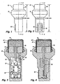
- FIG. 1 is a side view of a pyrotechnic initiator of the present invention.
- FIG. 2 is a front view of the initiator of FIG. 1.
- FIG. 3 is a sectional view taken through lines 3-3 of FIG. 1.
- FIG. 4 is a sectional view taken through lines 4-4 of FIG. 2.
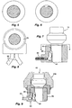
- FIG. 5 is a top view of the initiator of FIG. 1.
- FIG. 6 is a bottom view of the initiator of FIG. 1.
- FIG. 7 is a sectional view of a mating connector with the connector end of the initiator of FIG. 1 inserted into it.
- FIG. 8 is a top view taken trough lines 8-8 of FIG. 7.
- FIG. 9 is a sectional view similar to that of FIG. 7, but also showing the inflator into which the pyrotechnic charge-loaded end of the initiator of FIG. 1 is inserted.
- As can be seen from Figs. 1-9, in a preferred embodiment of the present invention, an
initiator assembly 10 has amating connector 80 and interconnections that are reconfigured in order to create space for an on-board PCB 30. Referring to Figs. 3 and 4, it can be seen thatinitiator assembly 10 includes a generally conventional ignition element comprising aheader eyelet 44,ground electrode pin 22,glass insulator 48, and isolatedelectrode pin 21, and apyrotechnic charge 46 enclosed in output can 42. - PCB 30, however, which includes a
board 31 andelectronic components 32, is enclosed by initiator moldedbody 20, and provided as an integral part of the initiator that can be supplied as one piece to inflator manufacturers. PCB 30 is placed outside the gas seal area, away from crimping stresses incurred during installation of the inflator 100 (see Fig. 9), and away from the high compressive loads of firing. Because PCB 30 is kept in a less exposed, less stressed part of the initiator, it has an increased chance of survival and communication after deployment of the airbag.Pins electrical interface 60, which is configured to slidingly mate with the mating connector (Figs. 7-9). It should also be noted that, as shown in the depicted embodiment, output can 42 andinsulator cup 40 can be suitably flared at their bottoms to enhance their retention ininitiator assembly 10. - Turning to Figs. 7-9,
mating connector 80 includes aconventional bus wire 89, but has an enlargedopening 88 defined by connector moldedbody 85, and a bus wireelectrical interface 90. Bus wireelectrical interface 90 is preferably configured to elastically deform enough to permit the connector end ofinitiator assembly 10 to be slidingly received, with initiatorelectrical interface 60 and bus wireelectrical interface 90 held snugly together in secure electrical contact. - With a standardized interface between electronics and the inflator, several different types of PCB assemblies may be incorporated with an ignition element. The PCB may be produced by an outside vendor, encapsulated, and supplied to an initiator manufacturer who can then appropriately attach it to pins 21 and 22 and mold it for final assembly, such as by insert injection molding with suitable thermoplastic or thermoset material.
- As a result of placing the control circuitry within the initiator in accordance with the present invention, the initiator and mating connector can have a beneficially compact overall size, and can, for example, be made with an overall axial length of under 21 millimeters.
- A preferred pyrotechnic initiator having on-board electronics, and a mating connector therefor, and many of their attendant advantages, have thus been disclosed. It will be apparent, however, that various changes may be made in the form, construction and arrangement of the parts or in the steps of the process, the form and process hereinbefore described being merely a preferred or exemplary embodiment thereof. Therefore, the invention is not to be restricted or limited except in accordance with the following claims.
Claims (13)
- An automotive pyrotechnic initiator assembly (10) comprising a pyrotechnic ignition element including two electrode pins (21, 22), an initiator body (20) enclosing said electrode pins (21, 22), an initiator electrical interface (60) including an exposed portion not enclosed within said initiator body (20), and control circuitry (30) attached to said electrode pins (21, 22) and said initiator electrical interface (60) and enclosed by said initiator body (20), the assembly (10) being characterized in that:said exposed portion includes at least one exposed electrical contact that is directly lateral to at least part of said control circuitry (30).
- The assembly (10) of claim 1, wherein said initiator body (20) is molded.
- The assembly (10) of claim 1, wherein said initiator assembly (10) includes a gas seal area, and said control circuitry (30) is remote from said gas seal area.
- The assembly (10) of any of claims 1 to 3, wherein the overall axial length of said initiator assembly (10) is less than 21 millimeters.
- The assembly (10) of any of claims 1 to 3, wherein said ignition element includes an output can (42) having a flared bottom that is enclosed within said initiator body (20).
- The assembly (10) of any of claims 1 to 3, wherein said ignition element includes an insulator cup (40) having a flared bottom that is enclosed within said initiator body (20).
- The assembly (10) of any of claims 1 to 3, wherein said control circuitry (30) is pre-encapsulated.
- The assembly (10) of any of claims 1 to 3, for use with a mating connector (80) that has an enlarged opening (88) with an inner profile, wherein said assembly (10) has an outer profile that matches the inner profile of said enlarged opening (88).
- An automotive pyrotechnic initiator and mating connector assembly comprising:a) the assembly (10) of claim 1;b) a mating connector body (85) including an enlarged initiator opening (88) defined therein, said enlarged initiator opening (88) formed to receive a portion of said initiator body (20) enclosing said control circuitry (30); andc) a bus wire (89) connected to said mating connector body (85) and including a bus wire electrical interface (90) disposed within said enlarged initiator opening (88), said bus wire electrical interface (90) formed to mate with said initiator electrical interface (60).
- The assembly of claim 9, wherein said enlarged initiator opening (88) includes an engagement feature formed to snugly hold said initiator body (20) in place when said initiator body (20) is received within said enlarged initiator opening (88).
- The assembly of claim 10, further configured to elastically deform when said initiator body (20) is received within said enlarged initiator opening (88), with the resulting degree of elastic deformation of said bus wire electrical interface (90) being selected to ensure that the initiator body (20) is held snugly within said enlarged initiator opening (88) and to ensure that said electrical interfaces are held snugly together in electrical contact.
- The assembly of claim 10, wherein said enlarged initiator opening (88) includes a radial orientation feature.
- The assembly of any of claims 9 to 12, wherein the overall axial length of said initiator and mating connector assembly is less than 21 millimeters when said initiator body (20) is fully received within said enlarged initiator opening (88).
Applications Claiming Priority (3)
| Application Number | Priority Date | Filing Date | Title |
|---|---|---|---|
| US899398 | 1997-07-23 | ||
| US09/899,398 US6915744B2 (en) | 2001-07-05 | 2001-07-05 | Pyrotechnic initiator with on-board control circuitry |
| PCT/US2002/021173 WO2003004959A2 (en) | 2001-07-05 | 2002-07-03 | Pyrotechnic initiator with on-board control circuitry |
Publications (3)
| Publication Number | Publication Date |
|---|---|
| EP1402226A2 EP1402226A2 (en) | 2004-03-31 |
| EP1402226A4 EP1402226A4 (en) | 2004-12-01 |
| EP1402226B1 true EP1402226B1 (en) | 2006-03-22 |
Family
ID=25410894
Family Applications (1)
| Application Number | Title | Priority Date | Filing Date |
|---|---|---|---|
| EP02761034A Expired - Lifetime EP1402226B1 (en) | 2001-07-05 | 2002-07-03 | Pyrotechnic initiator with on-board control circuitry |
Country Status (7)
| Country | Link |
|---|---|
| US (1) | US6915744B2 (en) |
| EP (1) | EP1402226B1 (en) |
| JP (1) | JP2004535547A (en) |
| AT (1) | ATE321253T1 (en) |
| AU (1) | AU2002326331A1 (en) |
| DE (1) | DE60210108T2 (en) |
| WO (1) | WO2003004959A2 (en) |
Families Citing this family (11)
| Publication number | Priority date | Publication date | Assignee | Title |
|---|---|---|---|---|
| US20030221576A1 (en) * | 2002-05-29 | 2003-12-04 | Forman David M. | Detonator with an ignition element having a transistor-type sealed feedthrough |
| US6907827B2 (en) * | 2002-11-14 | 2005-06-21 | Special Devices, Inc. | Pyrotechnic initiator having output can with encapsulation material retention feature |
| US7690303B2 (en) * | 2004-04-22 | 2010-04-06 | Reynolds Systems, Inc. | Plastic encapsulated energetic material initiation device |
| US8635872B2 (en) * | 2007-09-14 | 2014-01-28 | Ruag Ammotec Gmbh | Pyrotechnical actuator |
| US8100043B1 (en) | 2008-03-28 | 2012-01-24 | Reynolds Systems, Inc. | Detonator cartridge and methods of use |
| US8276516B1 (en) | 2008-10-30 | 2012-10-02 | Reynolds Systems, Inc. | Apparatus for detonating a triaminotrinitrobenzene charge |
| CN102257347B (en) * | 2008-11-05 | 2013-12-25 | 日本化药株式会社 | Ignition system and gas generating device for airbag loaded with same |
| US8267014B2 (en) * | 2009-12-22 | 2012-09-18 | The United States Of America As Represented By The Secretary Of The Navy | Multiple-bay ejection device |
| US8485097B1 (en) | 2010-06-11 | 2013-07-16 | Reynolds Systems, Inc. | Energetic material initiation device |
| WO2017197389A1 (en) * | 2016-05-13 | 2017-11-16 | Tk Holdings Inc. | Smart initiator assembly |
| DE102018127036B4 (en) | 2018-10-30 | 2024-01-04 | Rheinmetall Waffe Munition Gmbh | IGNITION UNIT AND AMMUNITION |
Family Cites Families (14)
| Publication number | Priority date | Publication date | Assignee | Title |
|---|---|---|---|---|
| WO1987000265A1 (en) | 1985-06-28 | 1987-01-15 | Moorhouse, D., J. | Detonator actuator |
| FR2669725B1 (en) * | 1990-11-27 | 1994-10-07 | Thomson Brandt Armements | PYROTECHNIC DETONATOR WITH COAXIAL CONNECTIONS. |
| US5200574A (en) * | 1991-04-05 | 1993-04-06 | Morton International, Inc. | Universal squib connector |
| US5230287A (en) * | 1991-04-16 | 1993-07-27 | Thiokol Corporation | Low cost hermetically sealed squib |
| DE19610799C1 (en) * | 1996-03-19 | 1997-09-04 | Siemens Ag | Ignition device for triggering a restraint in a motor vehicle |
| GB2315118A (en) | 1996-07-11 | 1998-01-21 | Ici Plc | Electro-explosvie device |
| FR2754050B1 (en) * | 1996-10-01 | 1998-10-30 | Livbag Snc | PYROTECHNIC GAS MICROGENERATOR WITH BLOCKED TWO-WIRE SOCKET |
| US6079332A (en) * | 1996-11-01 | 2000-06-27 | The Ensign-Bickford Company | Shock-resistant electronic circuit assembly |
| US5889228A (en) * | 1997-04-09 | 1999-03-30 | The Ensign-Bickford Company | Detonator with loosely packed ignition charge and method of assembly |
| US6070531A (en) * | 1997-07-22 | 2000-06-06 | Autoliv Asp, Inc. | Application specific integrated circuit package and initiator employing same |
| DE19733353C1 (en) * | 1997-08-01 | 1998-12-10 | Nico Pyrotechnik | Ignition unit for a personal protection device in a motor vehicle |
| US6164208A (en) * | 1998-07-14 | 2000-12-26 | Chung Shan Institute Of Science & Technology | Igniter for vehicle airbag inflator |
| AU2285900A (en) | 1999-01-08 | 2000-07-24 | Dynamit Nobel Gmbh Explosivstoff- Und Systemtechnik | Control module for triggering units for initiating pyrotechnical elements |
| US6341562B1 (en) * | 2000-02-22 | 2002-01-29 | Autoliv Asp, Inc. | Initiator assembly with activation circuitry |
-
2001
- 2001-07-05 US US09/899,398 patent/US6915744B2/en not_active Expired - Lifetime
-
2002
- 2002-07-03 WO PCT/US2002/021173 patent/WO2003004959A2/en active IP Right Grant
- 2002-07-03 AT AT02761034T patent/ATE321253T1/en active
- 2002-07-03 AU AU2002326331A patent/AU2002326331A1/en not_active Abandoned
- 2002-07-03 JP JP2003510888A patent/JP2004535547A/en active Pending
- 2002-07-03 EP EP02761034A patent/EP1402226B1/en not_active Expired - Lifetime
- 2002-07-03 DE DE60210108T patent/DE60210108T2/en not_active Expired - Lifetime
Also Published As
| Publication number | Publication date |
|---|---|
| DE60210108T2 (en) | 2006-10-12 |
| ATE321253T1 (en) | 2006-04-15 |
| US20030005843A1 (en) | 2003-01-09 |
| EP1402226A4 (en) | 2004-12-01 |
| DE60210108D1 (en) | 2006-05-11 |
| JP2004535547A (en) | 2004-11-25 |
| EP1402226A2 (en) | 2004-03-31 |
| WO2003004959A2 (en) | 2003-01-16 |
| US6915744B2 (en) | 2005-07-12 |
| WO2003004959A3 (en) | 2003-10-09 |
| AU2002326331A1 (en) | 2003-01-21 |
Similar Documents
| Publication | Publication Date | Title |
|---|---|---|
| US6341562B1 (en) | Initiator assembly with activation circuitry | |
| US5932832A (en) | High pressure resistant initiator with integral metal oxide varistor for electro-static discharge protection | |
| US4700973A (en) | Trigger system for a vehicular passenger restraint system | |
| EP0512682B1 (en) | Universal squib connector | |
| US5241910A (en) | Universal squib connector for a gas generator | |
| EP1038154B1 (en) | Bridgewire initiator | |
| US6227115B1 (en) | Ignition device for tripping a passenger restraint device in a motor vehicle | |
| EP1402226B1 (en) | Pyrotechnic initiator with on-board control circuitry | |
| US10203228B2 (en) | Crash sensor assembly | |
| US6848713B2 (en) | Airbag gas producer | |
| US5616881A (en) | Inflator socket pin collar for integrated circuit initaitor with integral metal oxide varistor for electro-static discharge protections | |
| KR20030034030A (en) | Orientationless squib connector assembly | |
| US10663269B2 (en) | Initiator grounding clip | |
| US6591754B1 (en) | Pyrotechnical ignition system with integrated ignition circuit | |
| EP1308691B2 (en) | Electric initiator and initiator assembly using it | |
| US6302023B1 (en) | Detonator for a pyrotechnical gas generator and gas generator | |
| WO1998002711A1 (en) | Electro-explosive device | |
| US20090266265A1 (en) | Ignition Device, Gas Generator for Air Bag and Gas Generator for Seat Belt Pretensioner | |
| US6650528B2 (en) | Ignition device for a safety system | |
| EP3134298B1 (en) | Surface mount initiators | |
| WO2003100343A1 (en) | Detonator with onboard electronics mechanically connected to ignition element | |
| WO1996012926A1 (en) | Semiconductor device packages | |
| JPH06312642A (en) | Air bag device | |
| MXPA97002543A (en) | High pressure resistant initiator, integrated with metallic oxide varistor for protection against download electrostat | |
| TH48928A (en) | Gas generator for air bags |
Legal Events
| Date | Code | Title | Description |
|---|---|---|---|
| PUAI | Public reference made under article 153(3) epc to a published international application that has entered the european phase |
Free format text: ORIGINAL CODE: 0009012 |
|
| 17P | Request for examination filed |
Effective date: 20031223 |
|
| AK | Designated contracting states |
Kind code of ref document: A2 Designated state(s): AT BE BG CH CY CZ DE DK EE ES FI FR GB GR IE IT LI LU MC NL PT SE SK TR |
|
| AX | Request for extension of the european patent |
Extension state: AL LT LV MK RO SI |
|
| RIC1 | Information provided on ipc code assigned before grant |
Ipc: 7F 42C 19/12 B Ipc: 7F 42B 3/10 B Ipc: 7F 42B 3/04 B Ipc: 7F 42C 19/06 B Ipc: 7F 42B 3/02 A Ipc: 7F 42C 19/08 B Ipc: 7F 42B 3/12 B |
|
| A4 | Supplementary search report drawn up and despatched |
Effective date: 20041013 |
|
| 17Q | First examination report despatched |
Effective date: 20050224 |
|
| GRAP | Despatch of communication of intention to grant a patent |
Free format text: ORIGINAL CODE: EPIDOSNIGR1 |
|
| GRAS | Grant fee paid |
Free format text: ORIGINAL CODE: EPIDOSNIGR3 |
|
| GRAA | (expected) grant |
Free format text: ORIGINAL CODE: 0009210 |
|
| AK | Designated contracting states |
Kind code of ref document: B1 Designated state(s): AT BE BG CH CY CZ DE DK EE ES FI FR GB GR IE IT LI LU MC NL PT SE SK TR |
|
| PG25 | Lapsed in a contracting state [announced via postgrant information from national office to epo] |
Ref country code: IT Free format text: LAPSE BECAUSE OF FAILURE TO SUBMIT A TRANSLATION OF THE DESCRIPTION OR TO PAY THE FEE WITHIN THE PRESCRIBED TIME-LIMIT;WARNING: LAPSES OF ITALIAN PATENTS WITH EFFECTIVE DATE BEFORE 2007 MAY HAVE OCCURRED AT ANY TIME BEFORE 2007. THE CORRECT EFFECTIVE DATE MAY BE DIFFERENT FROM THE ONE RECORDED. Effective date: 20060322 Ref country code: BE Free format text: LAPSE BECAUSE OF FAILURE TO SUBMIT A TRANSLATION OF THE DESCRIPTION OR TO PAY THE FEE WITHIN THE PRESCRIBED TIME-LIMIT Effective date: 20060322 Ref country code: SK Free format text: LAPSE BECAUSE OF FAILURE TO SUBMIT A TRANSLATION OF THE DESCRIPTION OR TO PAY THE FEE WITHIN THE PRESCRIBED TIME-LIMIT Effective date: 20060322 Ref country code: NL Free format text: LAPSE BECAUSE OF FAILURE TO SUBMIT A TRANSLATION OF THE DESCRIPTION OR TO PAY THE FEE WITHIN THE PRESCRIBED TIME-LIMIT Effective date: 20060322 |
|
| REG | Reference to a national code |
Ref country code: GB Ref legal event code: FG4D |
|
| REG | Reference to a national code |
Ref country code: CH Ref legal event code: EP |
|
| REG | Reference to a national code |
Ref country code: IE Ref legal event code: FG4D |
|
| REF | Corresponds to: |
Ref document number: 60210108 Country of ref document: DE Date of ref document: 20060511 Kind code of ref document: P |
|
| PG25 | Lapsed in a contracting state [announced via postgrant information from national office to epo] |
Ref country code: SE Free format text: LAPSE BECAUSE OF FAILURE TO SUBMIT A TRANSLATION OF THE DESCRIPTION OR TO PAY THE FEE WITHIN THE PRESCRIBED TIME-LIMIT Effective date: 20060622 Ref country code: BG Free format text: LAPSE BECAUSE OF FAILURE TO SUBMIT A TRANSLATION OF THE DESCRIPTION OR TO PAY THE FEE WITHIN THE PRESCRIBED TIME-LIMIT Effective date: 20060622 Ref country code: DK Free format text: LAPSE BECAUSE OF FAILURE TO SUBMIT A TRANSLATION OF THE DESCRIPTION OR TO PAY THE FEE WITHIN THE PRESCRIBED TIME-LIMIT Effective date: 20060622 |
|
| REG | Reference to a national code |
Ref country code: CH Ref legal event code: NV Representative=s name: PATENTANWAELTE SCHAAD, BALASS, MENZL & PARTNER AG |
|
| PG25 | Lapsed in a contracting state [announced via postgrant information from national office to epo] |
Ref country code: ES Free format text: LAPSE BECAUSE OF FAILURE TO SUBMIT A TRANSLATION OF THE DESCRIPTION OR TO PAY THE FEE WITHIN THE PRESCRIBED TIME-LIMIT Effective date: 20060703 Ref country code: IE Free format text: LAPSE BECAUSE OF NON-PAYMENT OF DUE FEES Effective date: 20060703 Ref country code: GB Free format text: LAPSE BECAUSE OF NON-PAYMENT OF DUE FEES Effective date: 20060703 |
|
| PG25 | Lapsed in a contracting state [announced via postgrant information from national office to epo] |
Ref country code: MC Free format text: LAPSE BECAUSE OF NON-PAYMENT OF DUE FEES Effective date: 20060731 |
|
| PG25 | Lapsed in a contracting state [announced via postgrant information from national office to epo] |
Ref country code: PT Free format text: LAPSE BECAUSE OF FAILURE TO SUBMIT A TRANSLATION OF THE DESCRIPTION OR TO PAY THE FEE WITHIN THE PRESCRIBED TIME-LIMIT Effective date: 20060822 |
|
| NLV1 | Nl: lapsed or annulled due to failure to fulfill the requirements of art. 29p and 29m of the patents act | ||
| ET | Fr: translation filed | ||
| PLBE | No opposition filed within time limit |
Free format text: ORIGINAL CODE: 0009261 |
|
| STAA | Information on the status of an ep patent application or granted ep patent |
Free format text: STATUS: NO OPPOSITION FILED WITHIN TIME LIMIT |
|
| 26N | No opposition filed |
Effective date: 20061227 |
|
| GBPC | Gb: european patent ceased through non-payment of renewal fee |
Effective date: 20060703 |
|
| PG25 | Lapsed in a contracting state [announced via postgrant information from national office to epo] |
Ref country code: GR Free format text: LAPSE BECAUSE OF FAILURE TO SUBMIT A TRANSLATION OF THE DESCRIPTION OR TO PAY THE FEE WITHIN THE PRESCRIBED TIME-LIMIT Effective date: 20060623 |
|
| PG25 | Lapsed in a contracting state [announced via postgrant information from national office to epo] |
Ref country code: EE Free format text: LAPSE BECAUSE OF FAILURE TO SUBMIT A TRANSLATION OF THE DESCRIPTION OR TO PAY THE FEE WITHIN THE PRESCRIBED TIME-LIMIT Effective date: 20060322 Ref country code: FI Free format text: LAPSE BECAUSE OF FAILURE TO SUBMIT A TRANSLATION OF THE DESCRIPTION OR TO PAY THE FEE WITHIN THE PRESCRIBED TIME-LIMIT Effective date: 20060322 |
|
| PG25 | Lapsed in a contracting state [announced via postgrant information from national office to epo] |
Ref country code: LU Free format text: LAPSE BECAUSE OF NON-PAYMENT OF DUE FEES Effective date: 20060703 Ref country code: TR Free format text: LAPSE BECAUSE OF FAILURE TO SUBMIT A TRANSLATION OF THE DESCRIPTION OR TO PAY THE FEE WITHIN THE PRESCRIBED TIME-LIMIT Effective date: 20060322 |
|
| PG25 | Lapsed in a contracting state [announced via postgrant information from national office to epo] |
Ref country code: CY Free format text: LAPSE BECAUSE OF FAILURE TO SUBMIT A TRANSLATION OF THE DESCRIPTION OR TO PAY THE FEE WITHIN THE PRESCRIBED TIME-LIMIT Effective date: 20060322 |
|
| REG | Reference to a national code |
Ref country code: CH Ref legal event code: PFA Owner name: SPECIAL DEVICES, INC. Free format text: SPECIAL DEVICES, INC.#14370 WHITE SAGE ROAD#MOORPARK, CA 93021 (US) -TRANSFER TO- SPECIAL DEVICES, INC.#3431 NORTH RESEDA CIRCLE#MESA, ARIZONA 85215 (US) |
|
| REG | Reference to a national code |
Ref country code: DE Ref legal event code: R082 Ref document number: 60210108 Country of ref document: DE Representative=s name: VIERING, JENTSCHURA & PARTNER, DE |
|
| REG | Reference to a national code |
Ref country code: FR Ref legal event code: CA Effective date: 20120924 |
|
| REG | Reference to a national code |
Ref country code: DE Ref legal event code: R082 Ref document number: 60210108 Country of ref document: DE Representative=s name: VIERING, JENTSCHURA & PARTNER, DE Effective date: 20121004 Ref country code: DE Ref legal event code: R081 Ref document number: 60210108 Country of ref document: DE Owner name: SPECIAL DEVICES, INC., US Free format text: FORMER OWNER: SPECIAL DEVICES, INC., MOORPARK, US Effective date: 20121004 Ref country code: DE Ref legal event code: R082 Ref document number: 60210108 Country of ref document: DE Representative=s name: VIERING, JENTSCHURA & PARTNER PATENT- UND RECH, DE Effective date: 20121004 Ref country code: DE Ref legal event code: R081 Ref document number: 60210108 Country of ref document: DE Owner name: SPECIAL DEVICES, INC., MESA, US Free format text: FORMER OWNER: SPECIAL DEVICES, INC., MOORPARK, CALIF., US Effective date: 20121004 Ref country code: DE Ref legal event code: R082 Ref document number: 60210108 Country of ref document: DE Representative=s name: VIERING, JENTSCHURA & PARTNER MBB PATENT- UND , DE Effective date: 20121004 |
|
| REG | Reference to a national code |
Ref country code: FR Ref legal event code: PLFP Year of fee payment: 15 |
|
| REG | Reference to a national code |
Ref country code: FR Ref legal event code: PLFP Year of fee payment: 16 |
|
| REG | Reference to a national code |
Ref country code: FR Ref legal event code: PLFP Year of fee payment: 17 |
|
| PGFP | Annual fee paid to national office [announced via postgrant information from national office to epo] |
Ref country code: CZ Payment date: 20200625 Year of fee payment: 19 |
|
| PGFP | Annual fee paid to national office [announced via postgrant information from national office to epo] |
Ref country code: FR Payment date: 20200727 Year of fee payment: 19 Ref country code: DE Payment date: 20200618 Year of fee payment: 19 |
|
| PGFP | Annual fee paid to national office [announced via postgrant information from national office to epo] |
Ref country code: AT Payment date: 20200720 Year of fee payment: 19 Ref country code: CH Payment date: 20200724 Year of fee payment: 19 |
|
| PG25 | Lapsed in a contracting state [announced via postgrant information from national office to epo] |
Ref country code: CZ Free format text: LAPSE BECAUSE OF NON-PAYMENT OF DUE FEES Effective date: 20210703 |
|
| REG | Reference to a national code |
Ref country code: DE Ref legal event code: R119 Ref document number: 60210108 Country of ref document: DE |
|
| REG | Reference to a national code |
Ref country code: CH Ref legal event code: PL |
|
| REG | Reference to a national code |
Ref country code: AT Ref legal event code: MM01 Ref document number: 321253 Country of ref document: AT Kind code of ref document: T Effective date: 20210703 |
|
| PG25 | Lapsed in a contracting state [announced via postgrant information from national office to epo] |
Ref country code: LI Free format text: LAPSE BECAUSE OF NON-PAYMENT OF DUE FEES Effective date: 20210731 Ref country code: DE Free format text: LAPSE BECAUSE OF NON-PAYMENT OF DUE FEES Effective date: 20220201 Ref country code: CH Free format text: LAPSE BECAUSE OF NON-PAYMENT OF DUE FEES Effective date: 20210731 Ref country code: AT Free format text: LAPSE BECAUSE OF NON-PAYMENT OF DUE FEES Effective date: 20210703 |
|
| PG25 | Lapsed in a contracting state [announced via postgrant information from national office to epo] |
Ref country code: FR Free format text: LAPSE BECAUSE OF NON-PAYMENT OF DUE FEES Effective date: 20210731 |