EP1402943A1 - Filters employing porous strongly acidic polymers - Google Patents
Filters employing porous strongly acidic polymers Download PDFInfo
- Publication number
- EP1402943A1 EP1402943A1 EP20030077987 EP03077987A EP1402943A1 EP 1402943 A1 EP1402943 A1 EP 1402943A1 EP 20030077987 EP20030077987 EP 20030077987 EP 03077987 A EP03077987 A EP 03077987A EP 1402943 A1 EP1402943 A1 EP 1402943A1
- Authority
- EP
- European Patent Office
- Prior art keywords
- filter
- porous
- cover
- group
- polymer
- Prior art date
- Legal status (The legal status is an assumption and is not a legal conclusion. Google has not performed a legal analysis and makes no representation as to the accuracy of the status listed.)
- Granted
Links
Images


Classifications
-
- B—PERFORMING OPERATIONS; TRANSPORTING
- B01—PHYSICAL OR CHEMICAL PROCESSES OR APPARATUS IN GENERAL
- B01J—CHEMICAL OR PHYSICAL PROCESSES, e.g. CATALYSIS OR COLLOID CHEMISTRY; THEIR RELEVANT APPARATUS
- B01J20/00—Solid sorbent compositions or filter aid compositions; Sorbents for chromatography; Processes for preparing, regenerating or reactivating thereof
- B01J20/28—Solid sorbent compositions or filter aid compositions; Sorbents for chromatography; Processes for preparing, regenerating or reactivating thereof characterised by their form or physical properties
- B01J20/28014—Solid sorbent compositions or filter aid compositions; Sorbents for chromatography; Processes for preparing, regenerating or reactivating thereof characterised by their form or physical properties characterised by their form
- B01J20/2803—Sorbents comprising a binder, e.g. for forming aggregated, agglomerated or granulated products
-
- B—PERFORMING OPERATIONS; TRANSPORTING
- B01—PHYSICAL OR CHEMICAL PROCESSES OR APPARATUS IN GENERAL
- B01D—SEPARATION
- B01D53/00—Separation of gases or vapours; Recovering vapours of volatile solvents from gases; Chemical or biological purification of waste gases, e.g. engine exhaust gases, smoke, fumes, flue gases, aerosols
- B01D53/02—Separation of gases or vapours; Recovering vapours of volatile solvents from gases; Chemical or biological purification of waste gases, e.g. engine exhaust gases, smoke, fumes, flue gases, aerosols by adsorption, e.g. preparative gas chromatography
-
- B—PERFORMING OPERATIONS; TRANSPORTING
- B01—PHYSICAL OR CHEMICAL PROCESSES OR APPARATUS IN GENERAL
- B01J—CHEMICAL OR PHYSICAL PROCESSES, e.g. CATALYSIS OR COLLOID CHEMISTRY; THEIR RELEVANT APPARATUS
- B01J20/00—Solid sorbent compositions or filter aid compositions; Sorbents for chromatography; Processes for preparing, regenerating or reactivating thereof
- B01J20/22—Solid sorbent compositions or filter aid compositions; Sorbents for chromatography; Processes for preparing, regenerating or reactivating thereof comprising organic material
- B01J20/26—Synthetic macromolecular compounds
- B01J20/261—Synthetic macromolecular compounds obtained by reactions only involving carbon to carbon unsaturated bonds
-
- B—PERFORMING OPERATIONS; TRANSPORTING
- B01—PHYSICAL OR CHEMICAL PROCESSES OR APPARATUS IN GENERAL
- B01J—CHEMICAL OR PHYSICAL PROCESSES, e.g. CATALYSIS OR COLLOID CHEMISTRY; THEIR RELEVANT APPARATUS
- B01J20/00—Solid sorbent compositions or filter aid compositions; Sorbents for chromatography; Processes for preparing, regenerating or reactivating thereof
- B01J20/22—Solid sorbent compositions or filter aid compositions; Sorbents for chromatography; Processes for preparing, regenerating or reactivating thereof comprising organic material
- B01J20/26—Synthetic macromolecular compounds
- B01J20/265—Synthetic macromolecular compounds modified or post-treated polymers
-
- B—PERFORMING OPERATIONS; TRANSPORTING
- B01—PHYSICAL OR CHEMICAL PROCESSES OR APPARATUS IN GENERAL
- B01J—CHEMICAL OR PHYSICAL PROCESSES, e.g. CATALYSIS OR COLLOID CHEMISTRY; THEIR RELEVANT APPARATUS
- B01J20/00—Solid sorbent compositions or filter aid compositions; Sorbents for chromatography; Processes for preparing, regenerating or reactivating thereof
- B01J20/28—Solid sorbent compositions or filter aid compositions; Sorbents for chromatography; Processes for preparing, regenerating or reactivating thereof characterised by their form or physical properties
- B01J20/28002—Solid sorbent compositions or filter aid compositions; Sorbents for chromatography; Processes for preparing, regenerating or reactivating thereof characterised by their form or physical properties characterised by their physical properties
- B01J20/28004—Sorbent size or size distribution, e.g. particle size
-
- B—PERFORMING OPERATIONS; TRANSPORTING
- B01—PHYSICAL OR CHEMICAL PROCESSES OR APPARATUS IN GENERAL
- B01J—CHEMICAL OR PHYSICAL PROCESSES, e.g. CATALYSIS OR COLLOID CHEMISTRY; THEIR RELEVANT APPARATUS
- B01J20/00—Solid sorbent compositions or filter aid compositions; Sorbents for chromatography; Processes for preparing, regenerating or reactivating thereof
- B01J20/28—Solid sorbent compositions or filter aid compositions; Sorbents for chromatography; Processes for preparing, regenerating or reactivating thereof characterised by their form or physical properties
- B01J20/28014—Solid sorbent compositions or filter aid compositions; Sorbents for chromatography; Processes for preparing, regenerating or reactivating thereof characterised by their form or physical properties characterised by their form
- B01J20/28016—Particle form
-
- B—PERFORMING OPERATIONS; TRANSPORTING
- B01—PHYSICAL OR CHEMICAL PROCESSES OR APPARATUS IN GENERAL
- B01J—CHEMICAL OR PHYSICAL PROCESSES, e.g. CATALYSIS OR COLLOID CHEMISTRY; THEIR RELEVANT APPARATUS
- B01J20/00—Solid sorbent compositions or filter aid compositions; Sorbents for chromatography; Processes for preparing, regenerating or reactivating thereof
- B01J20/28—Solid sorbent compositions or filter aid compositions; Sorbents for chromatography; Processes for preparing, regenerating or reactivating thereof characterised by their form or physical properties
- B01J20/28014—Solid sorbent compositions or filter aid compositions; Sorbents for chromatography; Processes for preparing, regenerating or reactivating thereof characterised by their form or physical properties characterised by their form
- B01J20/28023—Fibres or filaments
-
- B—PERFORMING OPERATIONS; TRANSPORTING
- B01—PHYSICAL OR CHEMICAL PROCESSES OR APPARATUS IN GENERAL
- B01J—CHEMICAL OR PHYSICAL PROCESSES, e.g. CATALYSIS OR COLLOID CHEMISTRY; THEIR RELEVANT APPARATUS
- B01J20/00—Solid sorbent compositions or filter aid compositions; Sorbents for chromatography; Processes for preparing, regenerating or reactivating thereof
- B01J20/28—Solid sorbent compositions or filter aid compositions; Sorbents for chromatography; Processes for preparing, regenerating or reactivating thereof characterised by their form or physical properties
- B01J20/28014—Solid sorbent compositions or filter aid compositions; Sorbents for chromatography; Processes for preparing, regenerating or reactivating thereof characterised by their form or physical properties characterised by their form
- B01J20/28026—Particles within, immobilised, dispersed, entrapped in or on a matrix, e.g. a resin
-
- B—PERFORMING OPERATIONS; TRANSPORTING
- B01—PHYSICAL OR CHEMICAL PROCESSES OR APPARATUS IN GENERAL
- B01J—CHEMICAL OR PHYSICAL PROCESSES, e.g. CATALYSIS OR COLLOID CHEMISTRY; THEIR RELEVANT APPARATUS
- B01J20/00—Solid sorbent compositions or filter aid compositions; Sorbents for chromatography; Processes for preparing, regenerating or reactivating thereof
- B01J20/28—Solid sorbent compositions or filter aid compositions; Sorbents for chromatography; Processes for preparing, regenerating or reactivating thereof characterised by their form or physical properties
- B01J20/28014—Solid sorbent compositions or filter aid compositions; Sorbents for chromatography; Processes for preparing, regenerating or reactivating thereof characterised by their form or physical properties characterised by their form
- B01J20/28033—Membrane, sheet, cloth, pad, lamellar or mat
- B01J20/28035—Membrane, sheet, cloth, pad, lamellar or mat with more than one layer, e.g. laminates, separated sheets
-
- B—PERFORMING OPERATIONS; TRANSPORTING
- B01—PHYSICAL OR CHEMICAL PROCESSES OR APPARATUS IN GENERAL
- B01J—CHEMICAL OR PHYSICAL PROCESSES, e.g. CATALYSIS OR COLLOID CHEMISTRY; THEIR RELEVANT APPARATUS
- B01J20/00—Solid sorbent compositions or filter aid compositions; Sorbents for chromatography; Processes for preparing, regenerating or reactivating thereof
- B01J20/28—Solid sorbent compositions or filter aid compositions; Sorbents for chromatography; Processes for preparing, regenerating or reactivating thereof characterised by their form or physical properties
- B01J20/28014—Solid sorbent compositions or filter aid compositions; Sorbents for chromatography; Processes for preparing, regenerating or reactivating thereof characterised by their form or physical properties characterised by their form
- B01J20/28033—Membrane, sheet, cloth, pad, lamellar or mat
- B01J20/2804—Sheets with a specific shape, e.g. corrugated, folded, pleated, helical
-
- B—PERFORMING OPERATIONS; TRANSPORTING
- B01—PHYSICAL OR CHEMICAL PROCESSES OR APPARATUS IN GENERAL
- B01J—CHEMICAL OR PHYSICAL PROCESSES, e.g. CATALYSIS OR COLLOID CHEMISTRY; THEIR RELEVANT APPARATUS
- B01J20/00—Solid sorbent compositions or filter aid compositions; Sorbents for chromatography; Processes for preparing, regenerating or reactivating thereof
- B01J20/28—Solid sorbent compositions or filter aid compositions; Sorbents for chromatography; Processes for preparing, regenerating or reactivating thereof characterised by their form or physical properties
- B01J20/28014—Solid sorbent compositions or filter aid compositions; Sorbents for chromatography; Processes for preparing, regenerating or reactivating thereof characterised by their form or physical properties characterised by their form
- B01J20/28042—Shaped bodies; Monolithic structures
-
- B—PERFORMING OPERATIONS; TRANSPORTING
- B01—PHYSICAL OR CHEMICAL PROCESSES OR APPARATUS IN GENERAL
- B01J—CHEMICAL OR PHYSICAL PROCESSES, e.g. CATALYSIS OR COLLOID CHEMISTRY; THEIR RELEVANT APPARATUS
- B01J20/00—Solid sorbent compositions or filter aid compositions; Sorbents for chromatography; Processes for preparing, regenerating or reactivating thereof
- B01J20/28—Solid sorbent compositions or filter aid compositions; Sorbents for chromatography; Processes for preparing, regenerating or reactivating thereof characterised by their form or physical properties
- B01J20/28054—Solid sorbent compositions or filter aid compositions; Sorbents for chromatography; Processes for preparing, regenerating or reactivating thereof characterised by their form or physical properties characterised by their surface properties or porosity
- B01J20/28057—Surface area, e.g. B.E.T specific surface area
-
- B—PERFORMING OPERATIONS; TRANSPORTING
- B01—PHYSICAL OR CHEMICAL PROCESSES OR APPARATUS IN GENERAL
- B01J—CHEMICAL OR PHYSICAL PROCESSES, e.g. CATALYSIS OR COLLOID CHEMISTRY; THEIR RELEVANT APPARATUS
- B01J20/00—Solid sorbent compositions or filter aid compositions; Sorbents for chromatography; Processes for preparing, regenerating or reactivating thereof
- B01J20/28—Solid sorbent compositions or filter aid compositions; Sorbents for chromatography; Processes for preparing, regenerating or reactivating thereof characterised by their form or physical properties
- B01J20/28054—Solid sorbent compositions or filter aid compositions; Sorbents for chromatography; Processes for preparing, regenerating or reactivating thereof characterised by their form or physical properties characterised by their surface properties or porosity
- B01J20/28078—Pore diameter
- B01J20/28083—Pore diameter being in the range 2-50 nm, i.e. mesopores
-
- B—PERFORMING OPERATIONS; TRANSPORTING
- B01—PHYSICAL OR CHEMICAL PROCESSES OR APPARATUS IN GENERAL
- B01D—SEPARATION
- B01D2253/00—Adsorbents used in seperation treatment of gases and vapours
- B01D2253/10—Inorganic adsorbents
- B01D2253/102—Carbon
-
- B—PERFORMING OPERATIONS; TRANSPORTING
- B01—PHYSICAL OR CHEMICAL PROCESSES OR APPARATUS IN GENERAL
- B01D—SEPARATION
- B01D2253/00—Adsorbents used in seperation treatment of gases and vapours
- B01D2253/20—Organic adsorbents
- B01D2253/202—Polymeric adsorbents
-
- B—PERFORMING OPERATIONS; TRANSPORTING
- B01—PHYSICAL OR CHEMICAL PROCESSES OR APPARATUS IN GENERAL
- B01D—SEPARATION
- B01D2253/00—Adsorbents used in seperation treatment of gases and vapours
- B01D2253/25—Coated, impregnated or composite adsorbents
-
- B—PERFORMING OPERATIONS; TRANSPORTING
- B01—PHYSICAL OR CHEMICAL PROCESSES OR APPARATUS IN GENERAL
- B01D—SEPARATION
- B01D2253/00—Adsorbents used in seperation treatment of gases and vapours
- B01D2253/30—Physical properties of adsorbents
- B01D2253/302—Dimensions
- B01D2253/306—Surface area, e.g. BET-specific surface
-
- B—PERFORMING OPERATIONS; TRANSPORTING
- B01—PHYSICAL OR CHEMICAL PROCESSES OR APPARATUS IN GENERAL
- B01D—SEPARATION
- B01D2253/00—Adsorbents used in seperation treatment of gases and vapours
- B01D2253/30—Physical properties of adsorbents
- B01D2253/302—Dimensions
- B01D2253/308—Pore size
-
- B—PERFORMING OPERATIONS; TRANSPORTING
- B01—PHYSICAL OR CHEMICAL PROCESSES OR APPARATUS IN GENERAL
- B01D—SEPARATION
- B01D2257/00—Components to be removed
- B01D2257/40—Nitrogen compounds
- B01D2257/406—Ammonia
-
- B—PERFORMING OPERATIONS; TRANSPORTING
- B01—PHYSICAL OR CHEMICAL PROCESSES OR APPARATUS IN GENERAL
- B01D—SEPARATION
- B01D2258/00—Sources of waste gases
- B01D2258/02—Other waste gases
- B01D2258/0216—Other waste gases from CVD treatment or semi-conductor manufacturing
-
- B—PERFORMING OPERATIONS; TRANSPORTING
- B01—PHYSICAL OR CHEMICAL PROCESSES OR APPARATUS IN GENERAL
- B01D—SEPARATION
- B01D2259/00—Type of treatment
- B01D2259/40—Further details for adsorption processes and devices
- B01D2259/40083—Regeneration of adsorbents in processes other than pressure or temperature swing adsorption
- B01D2259/40084—Regeneration of adsorbents in processes other than pressure or temperature swing adsorption by exchanging used adsorbents with fresh adsorbents
-
- B—PERFORMING OPERATIONS; TRANSPORTING
- B01—PHYSICAL OR CHEMICAL PROCESSES OR APPARATUS IN GENERAL
- B01D—SEPARATION
- B01D2259/00—Type of treatment
- B01D2259/40—Further details for adsorption processes and devices
- B01D2259/414—Further details for adsorption processes and devices using different types of adsorbents
- B01D2259/4141—Further details for adsorption processes and devices using different types of adsorbents within a single bed
- B01D2259/4145—Further details for adsorption processes and devices using different types of adsorbents within a single bed arranged in series
- B01D2259/4146—Contiguous multilayered adsorbents
Definitions
- Gas phase filtration is commonly accomplished using activated carbon manufactured in various ways.
- One approach uses a carbon/adhesive slurry to glue the carbon to the substrate.
- the adhesive decreases carbon performance by forming a film on its surface.
- a second approach involves carbonizing an organic based web by heating, followed by carbon activation. This material is expensive and has relatively low adsorption capacity.
- a third approach involves forming a slurry of carbon powders and fibers into sheets by a process analogous to a wet papermaking process.
- This material has a medium-to-high cost, and has an undesirable high pressure drop.
- chemically impregnated carbon particles cannot be efficiently used in conjunction with an aqueous process, as the aqueous nature of the process either washes away the chemical used to impregnate the carbon, or reacts undesirably with the impregnating or active chemical groups thereby rendering it inoperative.
- filter materials which do not incorporate chemically active groups perform far less effectively than those which do include chemically active groups.
- the present invention comprises a clean, cost effective, high efficiency, low pressure drop, adsorptive, filter comprising a high surface area, highly acidic chemically impregnated adsorbent.
- a preferred embodiment of the invention can employ a non-woven composite material having acidic functional groups that bind to airborne bases.
- the invention can be used in lithography systems which employ materials that are sensitive to impurities, such as molecular bases present in the air circulating through semiconductor wafer processing equipment. A large number of bases including ammonia, NMP, triethylamine pyridine, and others, can be maintained at concentrations below 2 ppb in a tool cluster filtered with the present invention.
- the invention also includes methods for forming the filter comprising, for example, the dry application of an active adsorbent to a non-woven carrier material, which is then heated and calendered with cover sheets.
- the non-woven carrier materials can be polyester non-wovens, and the adsorbent can include sulfonated divinyl benzene styrene copolymer.
- Another preferred embodiment employs carboxylic functional groups.
- the acidic groups have at least 1 milliequivalent/gram acidity level or higher and preferably at least 4.0 milliequivalents/gram or higher.
- the polymers used are porous, preferably having a pore size in the range of 50-400 angstroms and a surface area of 20m 2 /g or higher.
- the dry processing of a non-woven polyester batting allows for even distribution of adsorbent particles throughout the depth of the polyester batting. This provides an increased bed depth at a very low pressure drop, which is highly desirable since a twofold increase in bed depth can increase the filter's breakthrough time (time to failure) fourfold when using these thin fabric based sulfonic beds.
- the invention provides a clean, cost effective, high efficiency, low pressure drop, adsorptive non-woven filter composite, and a method for forming said composite.
- the novel filter composite is particularly useful for the removal of base contaminants in an air stream, which contaminants can be gaseous or vaporous. Particulates will also be removed if greater than the pore size of the filter.
- the filter has a service life of at least 12 months with a pressure drop to reduce power consumption and minimize impact on the systems operation. For example, a high pressure drop filter can require a longer time for a lithography system to equilibrate the temperature and humidity after filter replacement.
- the filter uses both sulfonated divinyl benzene styrene copolymer and an activated carbon as the adsorbent.
- Activated carbon is discussed in greater detail in U.S. Patent No. 5,582,865 titled ''Non-Woven Filter Composite.” The entire contents of this patent is incorporated herein by reference.
- the filter in this preferred embodiment has two (or more) layers, one of activated carbon and one of sulfonated divinyl benzene styrene copolymer beads. Additionally, two or more materials can be mixed to provide the filter system of the present invention.
- a synthetic carbon material such as that described in U.S. Patent No. 5,834,114, the contents of which are incorporated herein by reference, can be coated with the materials of the present invention to provide a porous acidic filter in accordance with the invention.
- a preferred embodiment of a method of fabricating a filter element having a large surface area and the desired flow characteristics involves the use of a powdered material that is deposited in sequential layers one on top of the other. Following the deposit of each layer of powdered material, a binder material is delivered onto each layer of powdered material using a printing technique in accordance with a computer model of the three dimensional filter element being formed. Following the sequential application of all of the required powder layers and binder material to form the part in question, the unbound powder is appropriately removed, resulting in the formation of the desired three dimensional filter element.
- This technique provides for the fabrication of complex unitary or composite filter elements having high surface area that are formed with a very high degree of resolution.
- the composite 16 has a cover sheet 66 and a middle layer 62.
- the cover sheet 66 is a polyester non woven having a binder to fiber ratio of 53/44 and a thickness of 0.024 inches.
- the middle layer 62 is air-laid polyester non woven having a thickness of 0.25 inches and binder to fiber ratio of 35%/65%.
- the composite is impregnated with a porous acidic polymer material that binds readily with molecular bases in air flowing through the filter.
- the structure of FIG. 2A can be used directly in this form as the composite filter element.
- the composite 16 in a preferred embodiment employs a second cover sheet 80, provided on the surface of middle layer 62, opposite to the first cover sheet 66 backing 12, as shown in FIG. 2B.
- a second cover sheet 14a can be provided over the backing layer 12, as shown in FIG, 2C.
- the cover sheet can be a filtering or non-filtering non-woven polyester, polyamide or polypropylene material or other similar materials. If the cover sheet is a filtering material, it serves to provide some filtering of the air entering the composite structure for removal of particulate materials in the air stream.
- the cover can also serve to retain the porous acidic polymer material such as a sulfonated divinyl benzene styrene copolymer, which can be in bead form, within the middle layer or batting 62.
- the cover sheets can also be chemically inert materials such as polypropylene.
- the composite 16 can be contained within any suitable container or frame work for installation in an intended position for filtering operation, typically in the form of a removable or replaceable filter element.
- any suitable container or frame work for installation in an intended position for filtering operation typically in the form of a removable or replaceable filter element.
- FIG. 3A One embodiment is shown in FIG. 3A, in which the composite material forms an air filter 15 or 17.
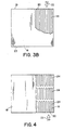
- the filter material is pleated into an accordion like structure 19 as shown in FIG. 3B, contained within a square or rectangular container 18, having a front 21, and back 23, which are open to an air stream shown by arrow 22.
- the pleating 20 is substantially perpendicular to the air flow.
- FIG. 3A shows the structure in a front or back view.
- FIG. 3B shows a cutaway top view of a filter structure.
- FIG. 4 An alternative embodiment is shown in FIG. 4 wherein a plurality of pleated composite elements 24, are sequentially disposed within container 18, to provide a multi-stage filter through which the air can pass.
- the pleats 20, of the elements 24, are substantially perpendicular to the direction of air flow 22.
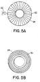
- FIG. 5A A further embodiment is shown in FIG. 5A, wherein the composite structure 16, is disposed in a cylindrical configuration and retained within a cylindrical container 28.
- the pleats 20, are as described above, substantially perpendicular to a radially directed air flow.
- FIG. 5B A further embodiment is shown in FIG. 5B wherein the composite structure is wound in a spiral configuration 30, contained within a generally cylindrical container 28.
- adsorbent particles are evenly distributed throughout the non-woven or fiber matrix or polyester batting.
- An example of an adsorbent particle includes but is not limited to sulfonated divinyl benzene styrene copolymer.
- the ion exchange strongly acidic preliminary catalyst has the important properties including a particle size of between 0.3 and 1.2 mm, a porosity of approximately 0.30 ml/g, and an average pore diameter of 250 ⁇ .
- the catalyst preferably has a higher porosity of up to 300 ml/g, or higher.
- concentration of acid sites of approximately 1.8 meq/ml and surface area of 45 m 2 /g.
- AMBERLYST® 15DRY or AMBERLYST® 35DRY by Rohm and Haas.
- the dry processing of the fiber matrix which includes the combination of the fluidized bed sulfonated divinyl benzene styrene copolymer deposition process, the inherent stratification of the batting's density, and the even distribution of the sulfonated divinyl benzene styrene copolymer particles as well as stratification of the sulfonated divinyl benzene styrene copolymer particle size, allows for a fabric architecture having an increased bed depth at a very low pressure drop, which is highly desirable due to its high first pass efficiency coupled with its low operating cost.
- efficiency is defined by the formula X-Y/X wherein X is the upstream concentration of pollutant, and Y is the downstream concentration of pollutant.
- the filter can have a mix of an activated carbon and the preliminary catalyst material discussed above. This combination has sufficient porosity and strongly acidic groups to provide easy permanent removal of medium and strong bases and sufficient retention of weak bases from the airborne base contaminants.
- the filter can also include a porous polymer material.
- the filter as described is employed in filtering the air in environments such as semiconductor fabrication systems where there is a requirement for uncontaminated air of high quality.
- the middle air-laid polyester non woven lay 62 is collated to a cover sheet 66.
- the adsorbent particles 60 are positioned on a fiber matrix 62 from a fluidized bed 64.
- the sulfonated divinyl benzene styrene copolymer particles 60 are evenly stratified throughout the depth of the batting 62.
- an increased bed depth of adsorbent particles distributed throughout the batting is highly desirable as it increases residence time, increases exposure of the adsorbent particle surfaces, provides a low pressure drop, as well as substantially increasing the lifetime of the filter.
- the adsorbent particles 60 distributed in the matrix 62 are then heated, preferably using two zones 68, 70 of infrared energy at different wavelengths.
- the batting 62 is heated to an overall average temperature of between 250° and 350° F.
- the infrared energy causes the adsorbent particles to adhere to the batting at points where the particles contact the batting. This procedure avoids the necessity of raising the temperature of the entire batting to a point at, or near, the melting point of the polyester batting, which could cause the batting to melt and collapse thereby encasing the particles and destroying their chemical activity.
- the batting 62 is then calendared using a pair of calender rolls 76,78.
- the first of these rolls 76 can be temperature controlled which allows the heating and calendering steps to be carried out at a steady temperature of around 140°, and prevents overheating and subsequent melting of cover sheet and prevents over calendering of the fabric.
- the second roll, roll 78 is a rubber roll having a durometer that avoids crushing of the adsorbent particles.
- the pressure at which the batting is 2000 pounds across the 26 inch distance. Higher calendaring pressures can crush the particles particularly when those particles are activated carbon based, thereby forming dust, which cannot be retained in the filter composite and can consequently pass into the gas stream.
- a synthetic non-woven cover sheet 80 which helps to maintain the sulfonated divinyl benzene styrene copolymer in the batting, may be calendared with the batting 62, as discussed above. After the filter is formed, gussets or spacers are placed in the filter. The filter is sealed into a metal box.
- the material may be conducted over an upper roller 84 to facilitate cooling the material prior to further processing.
- the method of manufacture for an activated carbon filter is described in detail in U.S. Patent No. 5,582,865 titled “Non-Woven Filter Composite.” The entire contents of this patent is incorporated herein by reference.
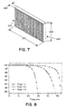
- FIG. 7 A pleated filter structure 220 using the porous acidic polymer of the present invention is illustrated in FIG. 7. This is a pleated system open on both sides of a rectangular frame 228 with a length 222, width 224 and depth such that it can be used as a replacement filter in stack filter systems.
- the filter has a removal efficiency of over 99% at 1000 ppb.
- FIG. 8 graphically illustrates the removal efficiency for three different filters.
- the graphs represent removal efficiency as a function of time at 20 ppm of NH 3 concentration upstream from the filter.
- Filter size is ⁇ 12"x12"x6".
- Air flow is ⁇ 100 cfm.
- Pressure drop of filter #1 was 0.2"WC; for filter #2 was 0.3"WC; and for filter #3 was 1.0"WC.
- Filters #1 and #2 are very close to tool manufacturer's specifications, but #3 creates an excessive pressure drop that interferes with tool's proper ECU functioning. Excessive pressure drop is undesirable for multiple reasons. For example, it increases fan load and power consumption, reduces airflow through the tool and positive pressure inside the enclosure.
- filter #1 made in accordance with the present invention provided a substantial improvement in service life while providing a pressure drop that is compatible with tool operation.
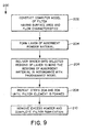
- Another preferred embodiment of the invention involves the fabrication of high surface area filter elements using a three dimensional printing technique as described in U.S. Patent Nos. 5,204,055, 5,340,656, and 5,387,380, the entire contents of these patents being incorporated herein by reference.
- the process 200 includes forming a three dimensional model 202 of the filter element such that the dimensions are well defined.
- the first layer of the powder material used to form the filter is placed 204 the printer apparatus.
- a binder is then delivered 206 onto the powder material resulting in the binding of selected regions thereof. Steps 204 and 206 are repeated a number of times until the high surface area filter is formed. Finally, the excess material is removed 210.
- An illustrative example of a high surface area filter made in accordance with this method is shown in the example 240 of FIG. 10.
- the binder can be an acid polymerizable or acid cross linkable liquid.
- Embodiments of the invention may include the features recited in the following enumerated paragraphs ("paras").
Abstract
Description
- This application claims the benefit of U.S. Provisional Application No. 60/097,215, filed on August 20,1998, the entire teachings of which are incorporated herein by reference.
- In this age of increased air pollution, the removal of chemicals from the air we breathe is a concern of everyone. In addition, in the fabrication electronic materials and of devices such as semiconductors, there is a requirement for uncontaminated air of high quality.
- Gas phase filtration is commonly accomplished using activated carbon manufactured in various ways. One approach uses a carbon/adhesive slurry to glue the carbon to the substrate. The adhesive decreases carbon performance by forming a film on its surface.
- A second approach involves carbonizing an organic based web by heating, followed by carbon activation. This material is expensive and has relatively low adsorption capacity.
- A third approach involves forming a slurry of carbon powders and fibers into sheets by a process analogous to a wet papermaking process. This material has a medium-to-high cost, and has an undesirable high pressure drop. Moreover, chemically impregnated carbon particles cannot be efficiently used in conjunction with an aqueous process, as the aqueous nature of the process either washes away the chemical used to impregnate the carbon, or reacts undesirably with the impregnating or active chemical groups thereby rendering it inoperative. In general, however, filter materials which do not incorporate chemically active groups perform far less effectively than those which do include chemically active groups.
- None of these approaches fully achieve the desired properties which provide a clean, cost effective, high efficiency, low pressure drop, adsorptive composite.
- The present invention comprises a clean, cost effective, high efficiency, low pressure drop, adsorptive, filter comprising a high surface area, highly acidic chemically impregnated adsorbent. A preferred embodiment of the invention can employ a non-woven composite material having acidic functional groups that bind to airborne bases. The invention can be used in lithography systems which employ materials that are sensitive to impurities, such as molecular bases present in the air circulating through semiconductor wafer processing equipment. A large number of bases including ammonia, NMP, triethylamine pyridine, and others, can be maintained at concentrations below 2 ppb in a tool cluster filtered with the present invention. The invention also includes methods for forming the filter comprising, for example, the dry application of an active adsorbent to a non-woven carrier material, which is then heated and calendered with cover sheets.
- In a preferred embodiment of this invention the non-woven carrier materials can be polyester non-wovens, and the adsorbent can include sulfonated divinyl benzene styrene copolymer. Another preferred embodiment employs carboxylic functional groups. The acidic groups have at least 1 milliequivalent/gram acidity level or higher and preferably at least 4.0 milliequivalents/gram or higher. The polymers used are porous, preferably having a pore size in the range of 50-400 angstroms and a surface area of 20m2/g or higher.
- The dry processing of a non-woven polyester batting allows for even distribution of adsorbent particles throughout the depth of the polyester batting. This provides an increased bed depth at a very low pressure drop, which is highly desirable since a twofold increase in bed depth can increase the filter's breakthrough time (time to failure) fourfold when using these thin fabric based sulfonic beds.
- Thus, the invention provides a clean, cost effective, high efficiency, low pressure drop, adsorptive non-woven filter composite, and a method for forming said composite. The novel filter composite is particularly useful for the removal of base contaminants in an air stream, which contaminants can be gaseous or vaporous. Particulates will also be removed if greater than the pore size of the filter. The filter has a service life of at least 12 months with a pressure drop to reduce power consumption and minimize impact on the systems operation. For example, a high pressure drop filter can require a longer time for a lithography system to equilibrate the temperature and humidity after filter replacement.
- In an alternative embodiment, the filter uses both sulfonated divinyl benzene styrene copolymer and an activated carbon as the adsorbent. Activated carbon is discussed in greater detail in U.S. Patent No. 5,582,865 titled ''Non-Woven Filter Composite." The entire contents of this patent is incorporated herein by reference. The filter in this preferred embodiment has two (or more) layers, one of activated carbon and one of sulfonated divinyl benzene styrene copolymer beads. Additionally, two or more materials can be mixed to provide the filter system of the present invention.
- In another preferred embodiment a synthetic carbon material, such as that described in U.S. Patent No. 5,834,114, the contents of which are incorporated herein by reference, can be coated with the materials of the present invention to provide a porous acidic filter in accordance with the invention.
- A detection system and method of use for determining when the filter needs to be replaced by detecting base contaminants in air is described in U.S. Patent Application No. 09/232,199 entitled "Detection of Base Contaminants in Gas Samples", filed on January 14, 1999 with Oleg Kishkovich, et al as inventors. Also U.S. Patent Application No. 08/795,949 entitled "Detecting of Base Contaminants", filed February 28, 1997 with Oleg Kishkovich, et al as inventors and U.S. Patent Application No. 08/996,790 entitled "Protection of Semiconductor Fabrication and Similar Sensitive Processes", filed December 23,1997 with Oleg Kishkovich, et al as inventors can also be used with the present invention. These patent applications disclose the protection of a DUV lithography processes using chemically amplified photoresists which are sensitive to amines in the air. These patent applications are incorporated in the present application in their entirety by reference.
- A preferred embodiment of a method of fabricating a filter element having a large surface area and the desired flow characteristics involves the use of a powdered material that is deposited in sequential layers one on top of the other. Following the deposit of each layer of powdered material, a binder material is delivered onto each layer of powdered material using a printing technique in accordance with a computer model of the three dimensional filter element being formed. Following the sequential application of all of the required powder layers and binder material to form the part in question, the unbound powder is appropriately removed, resulting in the formation of the desired three dimensional filter element. This technique provides for the fabrication of complex unitary or composite filter elements having high surface area that are formed with a very high degree of resolution.
- The foregoing and other objects, features and advantages of the invention will be apparent from the following more particular description of preferred embodiments of the invention, as illustrated in the accompanying drawings in which like reference characters refer to the same parts throughout the different views. The drawings are not necessarily to scale, emphasis instead being placed upon illustrating the principles of the invention.
- FIG. 1 is a perspective view of the apparatus of this invention before heating and calendaring;
- FIG. 2A is a perspective view of the apparatus of this invention after heating and calendaring;
- FIG. 2B is a perspective view of the apparatus of this invention after heating and calendaring with a cover sheet;
- FIG. 3A is a perspective view of the apparatus of this invention in a square or rectangular containment structure showing the creases of the pleated structure;
- FIG. 3B is a top view of the apparatus of this invention showing its pleated structure;
- FIG. 4 is a top view of the apparatus of this invention with a high first pass efficiency multi-pleat pack panel filter in a square or rectangular containment structure;
- FIG. 5A is a top view of the apparatus of this invention in a radially pleated cylindrical containment structure;
- FIG. 5B is top view ofthe apparatus of this invention in a media-wrapped cylindrical filter; and
- FIG. 6 is a perspective view of a process of producing a filter of the invention.
- FIG. 7 is a pleated filter made in accordance with the invention.
- FIG. 8 is a graphical illustration comprising the base removal efficiency of filters previously available and a filter made in accordance with the invention.
- FIG. 9 is a process for fabricating a filter in accordance with a preferred embodiment of the invention.
- FIG. 10 illustrates an example of a three dimensional filter fabricated in accordance with the process.
- Referring to FIG. 1, a portion of a composite 16 is shown. The composite 16 has a
cover sheet 66 and amiddle layer 62. In a preferred embodiment, thecover sheet 66 is a polyester non woven having a binder to fiber ratio of 53/44 and a thickness of 0.024 inches. Themiddle layer 62 is air-laid polyester non woven having a thickness of 0.25 inches and binder to fiber ratio of 35%/65%. The composite is impregnated with a porous acidic polymer material that binds readily with molecular bases in air flowing through the filter. - The structure of FIG. 2A can be used directly in this form as the composite filter element. The composite 16, in a preferred embodiment employs a
second cover sheet 80, provided on the surface ofmiddle layer 62, opposite to thefirst cover sheet 66 backing 12, as shown in FIG. 2B. Alternatively, a second cover sheet 14a, can be provided over the backing layer 12, as shown in FIG, 2C. The cover sheet can be a filtering or non-filtering non-woven polyester, polyamide or polypropylene material or other similar materials. If the cover sheet is a filtering material, it serves to provide some filtering of the air entering the composite structure for removal of particulate materials in the air stream. The cover can also serve to retain the porous acidic polymer material such as a sulfonated divinyl benzene styrene copolymer, which can be in bead form, within the middle layer orbatting 62. The cover sheets can also be chemically inert materials such as polypropylene. - The composite 16, can be contained within any suitable container or frame work for installation in an intended position for filtering operation, typically in the form of a removable or replaceable filter element. For many purposes, it is preferable to increase the surface area of the filter material exposed to an incident air flow, and for this purpose the composite can be pleated to provide the increased surface area.
- One embodiment is shown in FIG. 3A, in which the composite material forms an
air filter structure 19 as shown in FIG. 3B, contained within a square orrectangular container 18, having a front 21, and back 23, which are open to an air stream shown byarrow 22. Thepleating 20 is substantially perpendicular to the air flow. FIG. 3A shows the structure in a front or back view. FIG. 3B shows a cutaway top view of a filter structure. - An alternative embodiment is shown in FIG. 4 wherein a plurality of pleated
composite elements 24, are sequentially disposed withincontainer 18, to provide a multi-stage filter through which the air can pass. As in the above embodiment, thepleats 20, of theelements 24, are substantially perpendicular to the direction ofair flow 22. - A further embodiment is shown in FIG. 5A, wherein the
composite structure 16, is disposed in a cylindrical configuration and retained within acylindrical container 28. Thepleats 20, are as described above, substantially perpendicular to a radially directed air flow. A further embodiment is shown in FIG. 5B wherein the composite structure is wound in aspiral configuration 30, contained within a generallycylindrical container 28. - In a preferred embodiment, adsorbent particles are evenly distributed throughout the non-woven or fiber matrix or polyester batting. An example of an adsorbent particle includes but is not limited to sulfonated divinyl benzene styrene copolymer.
- In a preferred embodiment, the ion exchange strongly acidic preliminary catalyst has the important properties including a particle size of between 0.3 and 1.2 mm, a porosity of approximately 0.30 ml/g, and an average pore diameter of 250 Å. The catalyst preferably has a higher porosity of up to 300 ml/g, or higher. In addition in a preferred embodiment has the properties of concentration of acid sites of approximately 1.8 meq/ml and surface area of 45 m2/g. One such catalyst is sold under the tradename AMBERLYST® 15DRY or AMBERLYST® 35DRY by Rohm and Haas.
- Overall, the dry processing of the fiber matrix, which includes the combination of the fluidized bed sulfonated divinyl benzene styrene copolymer deposition process, the inherent stratification of the batting's density, and the even distribution of the sulfonated divinyl benzene styrene copolymer particles as well as stratification of the sulfonated divinyl benzene styrene copolymer particle size, allows for a fabric architecture having an increased bed depth at a very low pressure drop, which is highly desirable due to its high first pass efficiency coupled with its low operating cost.
- The term "efficiency" as employed herein is defined by the formula X-Y/X wherein X is the upstream concentration of pollutant, and Y is the downstream concentration of pollutant.
- It is recognized that the filter can have a mix of an activated carbon and the preliminary catalyst material discussed above. This combination has sufficient porosity and strongly acidic groups to provide easy permanent removal of medium and strong bases and sufficient retention of weak bases from the airborne base contaminants. The filter can also include a porous polymer material.
- The filter as described is employed in filtering the air in environments such as semiconductor fabrication systems where there is a requirement for uncontaminated air of high quality.
- Referring to Fig. 6, the middle air-laid polyester non woven lay 62 is collated to a
cover sheet 66. Theadsorbent particles 60 are positioned on afiber matrix 62 from afluidized bed 64. The sulfonated divinyl benzenestyrene copolymer particles 60 are evenly stratified throughout the depth of thebatting 62. As discussed above, an increased bed depth of adsorbent particles distributed throughout the batting is highly desirable as it increases residence time, increases exposure of the adsorbent particle surfaces, provides a low pressure drop, as well as substantially increasing the lifetime of the filter. - The
adsorbent particles 60 distributed in thematrix 62 are then heated, preferably using twozones batting 62 is heated to an overall average temperature of between 250° and 350° F. - The infrared energy causes the adsorbent particles to adhere to the batting at points where the particles contact the batting. This procedure avoids the necessity of raising the temperature of the entire batting to a point at, or near, the melting point of the polyester batting, which could cause the batting to melt and collapse thereby encasing the particles and destroying their chemical activity.
- The
batting 62 is then calendared using a pair of calender rolls 76,78. The first of theserolls 76 can be temperature controlled which allows the heating and calendering steps to be carried out at a steady temperature of around 140°, and prevents overheating and subsequent melting of cover sheet and prevents over calendering of the fabric. The second roll, roll 78, is a rubber roll having a durometer that avoids crushing of the adsorbent particles. - Furthermore, when the temperature controlled
roller 76 is used, the pressure at which the batting is 2000 pounds across the 26 inch distance. Higher calendaring pressures can crush the particles particularly when those particles are activated carbon based, thereby forming dust, which cannot be retained in the filter composite and can consequently pass into the gas stream. - In addition, a synthetic
non-woven cover sheet 80, which helps to maintain the sulfonated divinyl benzene styrene copolymer in the batting, may be calendared with thebatting 62, as discussed above. After the filter is formed, gussets or spacers are placed in the filter. The filter is sealed into a metal box. - Optionally, the material may be conducted over an
upper roller 84 to facilitate cooling the material prior to further processing. The method of manufacture for an activated carbon filter is described in detail in U.S. Patent No. 5,582,865 titled "Non-Woven Filter Composite." The entire contents of this patent is incorporated herein by reference. - While the above described method is a preferred method of creating the filter, it is recognized that other techniques can be used. Some of these techniques include those developed by Hoechst such as that described in U.S. Patent No. 5,605,746, the entire contents of which is incorporated herein by reference or KX Media. The common feature in all these methods are the incorporation of a chemically active sorbent into a porous media structure.
- A
pleated filter structure 220 using the porous acidic polymer of the present invention is illustrated in FIG. 7. This is a pleated system open on both sides of arectangular frame 228 with alength 222,width 224 and depth such that it can be used as a replacement filter in stack filter systems. The filter has a removal efficiency of over 99% at 1000 ppb. - FIG. 8 graphically illustrates the removal efficiency for three different filters. The graphs represent removal efficiency as a function of time at 20 ppm of NH3 concentration upstream from the filter. Filter size is ~ 12"x12"x6". Air flow is ~ 100 cfm. Considering service life data only, it appears that filter #3 performed best. However, if additional data is considered, the conclusion is not so simple. Pressure drop of filter #1 was 0.2"WC; for filter #2 was 0.3"WC; and for filter #3 was 1.0"WC. Filters #1 and #2 are very close to tool manufacturer's specifications, but #3 creates an excessive pressure drop that interferes with tool's proper ECU functioning. Excessive pressure drop is undesirable for multiple reasons. For example, it increases fan load and power consumption, reduces airflow through the tool and positive pressure inside the enclosure. Thus filter #1 made in accordance with the present invention provided a substantial improvement in service life while providing a pressure drop that is compatible with tool operation.
- Another preferred embodiment of the invention involves the fabrication of high surface area filter elements using a three dimensional printing technique as described in U.S. Patent Nos. 5,204,055, 5,340,656, and 5,387,380, the entire contents of these patents being incorporated herein by reference.
- Such a method of fabrication of a filter element is illustrated in connection with FIG. 9. The
process 200 includes forming a threedimensional model 202 of the filter element such that the dimensions are well defined. The first layer of the powder material used to form the filter is placed 204 the printer apparatus. A binder is then delivered 206 onto the powder material resulting in the binding of selected regions thereof.Steps - While this invention has been particularly shown and described with references to preferred embodiments thereof, it will be understood by those skilled in the art that various changes in form and details may be made therein without departing from the spirit and scope of the invention as defined by the appended claims.
- Embodiments of the invention may include the features recited in the following enumerated paragraphs ("paras").
- 1. A fluid-permeable filter comprising:
- a porous particulate material formed with a copolymer having an acidic functional group such that the group can react with a reagent; and
- a filter element having the porous particulate material.
- 2. The filter of para 1 wherein the particulate material comprises a porous divinyl benzene styrene copolymer having a sulfonic acid group
- 3. The filter of para 1 wherein the acidic group has an acidity level of at least 1 milliequivalent/gram.
- 4. The filter of para 1 wherein the material has a pore size in the range of 50-400 angstroms.
- 5. The filter of para 1 wherein the acidic functional group comprises a carboxylic acid.
- 6. The filter of para 1 wherein the filter comprises a pleated filter.
- 7. The filter of para 1 wherein the filter element has a surface area of 20 m2/g or higher.
- 8. A porous filter comprising:
- a filter having a porous material selected from the group of particles, threads, yarns, ribbons, fibers or filaments of a polymer,
- the polymer comprising an acid functional group selected from the group consisting of a sulfonic or carboxylic acid.
- 9. The filter of
para 8 wherein the material has an area of 20 m2/g. - 10. A method of filtering air for a fabrication facility needing uncontaminated air of high quality, comprising the steps of:
- providing a non-woven carrier material having a top surface and having thermo-plastic fibers of lower fiber density relative to the fiber density of the resultant composite; the woven carrier retaining adsorbent particles of a sulfonated divinyl benzene styrene copolymer;
- flowing air through the filter with the surfaces of said distributed adsorbent particles being exposed for contact with passing air; and
- removing the base contaminants from the air with the sulfonated material.
- 11. A method for forming a vapor absorptive non-woven air filter comprising thermo-plastic fibers and adsorptive particles, said composite having a fiber density, comprising the steps of:
- providing a non-woven carrier material having a surface and comprising thermo-plastic fibers;
- applying adsorbent particles of an acidic polymer to said surface of said carrier material.
- 12. The method of para 11 further comprising heating said carrier material and applied adsorbent particles; and
calendering the heated carrier material with said adsorbent particles distributed therein;
wherein said heating and calendering steps are performed for a period of time and under a pressure selected to be sufficient for said adsorbent particles to become retained within said heated and calendered carrier material to form a calendered composite having an open fibrous structure of said given fiber density with the surfaces of said distributed adsorbent particles being substantially exposed for contact with air passing through said calendered composite, said resulting non-woven air filter composite being characterized by a pressure drop sufficient for use as an air filter. - 13. The method of para 11 wherein the acidic polymer comprises a sulfonated copolymer.
- 14. The method of para 11 wherein the acidic polymer comprises a carboxylic copolymer.
- 15. An adsorptive, filter composite comprising:
- a porous sulfonated divinyl benzene styrene copolymer beads having sulfonic acid functional side groups used to remove molecular bases from air.
- 16. The filter composite of
para 15 wherein the filter removes molecular base materials from a semiconductor processing tool - 17. The filter composite of
para 15 wherein the beads have a surface area of 20 m2/g or greater. - 18. The filter composite of
para 15 further comprising a binder material. - 19. A filter element comprising alternating layers of a powder material and a binder.
- 20. The filter element of
para 19 wherein the binder includes an acid-polymerizable or acid-cross-linkable liquid. - 21. The filter element of
para 20 wherein the powder material includes divinyl benzene styrene copolymer. - 22. The filter element of
para 19 wherein the filter element is a component of a semiconductor processing tool. - 23. The filter element of
para 22 wherein the semiconductor processing tool includes a deep-ultraviolet photolithography device. - 24. A method for filtering molecular base contaminants from air in semiconductor processing equipment comprising passing air through a filter element comprising alternating layers of a powder material and a binder.
- 25. The method of
para 24 wherein the binder includes an acid-polymerizable or acid-cross-linkable liquid. - 26. The method of para 25 wherein the powder material includes divinyl benzene styrene copolymer.
- 27. The method of para 26 wherein the air is delivered to a deep-ultraviolet photolithography tool after passing though the filter element.
- 28. A method for forming a filter element comprising the steps of:
- a) forming a layer of adsorbent powder material;
- b) delivering binder onto selected regions of the layer of adsorbent powder material to bond the regions of adsorbent material in accordance with a programmed model; and
- c) repeating steps (a) and (b) until a filter element matching the programmed model is formed.
- 29. The method of
para 28 wherein the binder includes an acid-polymerizable or acid-cross-linkable liquid. - 30. The method of para 29 wherein the powder material includes divinyl benzene styrene copolymer.
- 31. The method of
para 28 further comprising the step of removing excess powder.
Claims (18)
- A fluid-permeable filter comprising:a porous polymer material having an acidic functional group such that the group can react with a base contaminant in a fluid passing through the filter, the filter having a cover in contact with the porous polymer material.
- The filter of Claim 1 wherein the polymer material comprises a porous divinyl benzene styrene copolymer having a sulfonic acid group.
- The filter of Claim 1 wherein the acidic group has an acidity level of at least 1 milliequivalent/gram.
- The filter of Claim 1 wherein the material has a pore size in the range of 50-400 angstroms.
- The filter of Claim 1 wherein the acidic functional group comprises a carboxylic acid.
- The filter of Claim 1 wherein the filter comprises a pleated filter.
- The filter of Claim 1 wherein the filter element has a surface area of 20 m2/g or higher.
- The filter of Claim 1 wherein the cover comprises a non-woven polymer sheet.
- The filter of Claim 1 wherein the cover forms a laminate structure with the porous material.
- The filter of Claim 1 further comprising a second cover such that the polymer material is between the cover and the second cover.
- The filter of Claim 1 wherein the cover comprises a filtering material.
- The filter of Claim 1 wherein the cover comprises a non-filtering material.
- The filter of Claim 1 wherein the cover comprises a material selected from the group of non-woven polyester, polyamide or polypropylene.
- The filter of Claim 1 wherein the acidic functional group comprises particles having a size in a range of 0.3 - 1.2 mm.
- A porous filter for a semiconductor processing tool comprising:a filter having a porous material selected from the group of particles, threads, yarns, ribbons, fibers or filaments of a polymer, the polymer comprising an acid functional group selected from the group consisting of a sulfonic or carboxylic acid; anda cover in contact with a surface of the porous material.
- The filter of Claim 15 wherein the material has a surface area of at least 20 m2/g.
- The filter of Claim 15 wherein the cover comprises a sheet attached to a first side of the porous material.
- The filter of Claim 15 wherein the sulfonic acid group comprises a particulate sulfonated divinyl benzene styrene copolymer.
Applications Claiming Priority (3)
| Application Number | Priority Date | Filing Date | Title |
|---|---|---|---|
| US97215 | 1991-02-11 | ||
| US9721598P | 1998-08-20 | 1998-08-20 | |
| EP99943864A EP1105203B1 (en) | 1998-08-20 | 1999-08-20 | Filters employing porous strongly acidic polymers |
Related Parent Applications (2)
| Application Number | Title | Priority Date | Filing Date |
|---|---|---|---|
| EP99943864.1 Division | 1999-08-20 | ||
| EP99943864A Division EP1105203B1 (en) | 1998-08-20 | 1999-08-20 | Filters employing porous strongly acidic polymers |
Publications (2)
| Publication Number | Publication Date |
|---|---|
| EP1402943A1 true EP1402943A1 (en) | 2004-03-31 |
| EP1402943B1 EP1402943B1 (en) | 2013-04-10 |
Family
ID=31979907
Family Applications (1)
| Application Number | Title | Priority Date | Filing Date |
|---|---|---|---|
| EP03077987.0A Expired - Lifetime EP1402943B1 (en) | 1998-08-20 | 1999-08-20 | Filters employing porous strongly acidic polymers |
Country Status (1)
| Country | Link |
|---|---|
| EP (1) | EP1402943B1 (en) |
Families Citing this family (1)
| Publication number | Priority date | Publication date | Assignee | Title |
|---|---|---|---|---|
| US6740147B2 (en) | 2000-05-05 | 2004-05-25 | Extraction Systems, Inc. | Filters employing both acidic polymers and physical-adsorption media |
Citations (5)
| Publication number | Priority date | Publication date | Assignee | Title |
|---|---|---|---|---|
| US3409691A (en) * | 1966-02-01 | 1968-11-05 | Dow Chemical Co | Porous cation exchange resins as selective sorbents in organic systems |
| US4313832A (en) * | 1980-06-12 | 1982-02-02 | Rohm And Haas Company | Method for treatment of aqueous solutions with ion exchange fibers |
| US4808202A (en) * | 1986-11-27 | 1989-02-28 | Unitka, Ltd. | Adsorptive fiber sheet |
| US5753345A (en) * | 1995-05-11 | 1998-05-19 | Kabushiki Kaisha Seibu Giken | Adsorber for humidity and odorous gas exchange |
| US5772738A (en) * | 1993-11-30 | 1998-06-30 | Purex Co., Ltd. | Multifunctional air filter and air-circulating clean unit with the same incorporated therein |
-
1999
- 1999-08-20 EP EP03077987.0A patent/EP1402943B1/en not_active Expired - Lifetime
Patent Citations (5)
| Publication number | Priority date | Publication date | Assignee | Title |
|---|---|---|---|---|
| US3409691A (en) * | 1966-02-01 | 1968-11-05 | Dow Chemical Co | Porous cation exchange resins as selective sorbents in organic systems |
| US4313832A (en) * | 1980-06-12 | 1982-02-02 | Rohm And Haas Company | Method for treatment of aqueous solutions with ion exchange fibers |
| US4808202A (en) * | 1986-11-27 | 1989-02-28 | Unitka, Ltd. | Adsorptive fiber sheet |
| US5772738A (en) * | 1993-11-30 | 1998-06-30 | Purex Co., Ltd. | Multifunctional air filter and air-circulating clean unit with the same incorporated therein |
| US5753345A (en) * | 1995-05-11 | 1998-05-19 | Kabushiki Kaisha Seibu Giken | Adsorber for humidity and odorous gas exchange |
Also Published As
| Publication number | Publication date |
|---|---|
| EP1402943B1 (en) | 2013-04-10 |
Similar Documents
| Publication | Publication Date | Title |
|---|---|---|
| EP1105203B1 (en) | Filters employing porous strongly acidic polymers | |
| EP1357998B1 (en) | Filters employing both acidic polymers and physical-adsorption media | |
| US5582865A (en) | Non-woven filter composite | |
| US7540901B2 (en) | Filters employing both acidic polymers and physical-adsorption media | |
| US5607647A (en) | Air filtering within clean environments | |
| US5869009A (en) | Filter device | |
| US5833726A (en) | Storing substrates between process steps within a processing facility | |
| WO2008098185A1 (en) | Combination filter element | |
| EP2040820B1 (en) | Filtering for a semiconductor processing tool | |
| EP1402943B1 (en) | Filters employing porous strongly acidic polymers |
Legal Events
| Date | Code | Title | Description |
|---|---|---|---|
| PUAI | Public reference made under article 153(3) epc to a published international application that has entered the european phase |
Free format text: ORIGINAL CODE: 0009012 |
|
| AC | Divisional application: reference to earlier application |
Ref document number: 1105203 Country of ref document: EP Kind code of ref document: P |
|
| AK | Designated contracting states |
Kind code of ref document: A1 Designated state(s): AT BE CH CY DE DK ES FI FR GB GR IE IT LI LU MC NL PT SE |
|
| 17P | Request for examination filed |
Effective date: 20040929 |
|
| AKX | Designation fees paid |
Designated state(s): AT BE CH CY DE DK ES FI FR GB GR IE IT LI LU MC NL PT SE |
|
| RAP1 | Party data changed (applicant data changed or rights of an application transferred) |
Owner name: MYKROLIS CORPORATION |
|
| RAP1 | Party data changed (applicant data changed or rights of an application transferred) |
Owner name: ENTEGRIS, INC. |
|
| 17Q | First examination report despatched |
Effective date: 20060821 |
|
| RAP1 | Party data changed (applicant data changed or rights of an application transferred) |
Owner name: ENTEGRIS, INC. |
|
| RIC1 | Information provided on ipc code assigned before grant |
Ipc: B01J 20/26 20060101AFI20120924BHEP Ipc: B01J 20/28 20060101ALI20120924BHEP Ipc: B01D 53/02 20060101ALI20120924BHEP |
|
| GRAP | Despatch of communication of intention to grant a patent |
Free format text: ORIGINAL CODE: EPIDOSNIGR1 |
|
| GRAS | Grant fee paid |
Free format text: ORIGINAL CODE: EPIDOSNIGR3 |
|
| GRAA | (expected) grant |
Free format text: ORIGINAL CODE: 0009210 |
|
| AC | Divisional application: reference to earlier application |
Ref document number: 1105203 Country of ref document: EP Kind code of ref document: P |
|
| AK | Designated contracting states |
Kind code of ref document: B1 Designated state(s): AT BE CH CY DE DK ES FI FR GB GR IE IT LI LU MC NL PT SE |
|
| REG | Reference to a national code |
Ref country code: GB Ref legal event code: FG4D |
|
| RIN1 | Information on inventor provided before grant (corrected) |
Inventor name: KISHKOVICH, OLEG Inventor name: REZUKE, ROBERT Inventor name: KINKEAD, KEVIN |
|
| REG | Reference to a national code |
Ref country code: CH Ref legal event code: EP Ref country code: AT Ref legal event code: REF Ref document number: 605680 Country of ref document: AT Kind code of ref document: T Effective date: 20130415 |
|
| REG | Reference to a national code |
Ref country code: IE Ref legal event code: FG4D |
|
| REG | Reference to a national code |
Ref country code: DE Ref legal event code: R096 Ref document number: 69944705 Country of ref document: DE Effective date: 20130606 |
|
| REG | Reference to a national code |
Ref country code: NL Ref legal event code: T3 |
|
| REG | Reference to a national code |
Ref country code: AT Ref legal event code: MK05 Ref document number: 605680 Country of ref document: AT Kind code of ref document: T Effective date: 20130410 |
|
| PG25 | Lapsed in a contracting state [announced via postgrant information from national office to epo] |
Ref country code: PT Free format text: LAPSE BECAUSE OF FAILURE TO SUBMIT A TRANSLATION OF THE DESCRIPTION OR TO PAY THE FEE WITHIN THE PRESCRIBED TIME-LIMIT Effective date: 20130812 Ref country code: GR Free format text: LAPSE BECAUSE OF FAILURE TO SUBMIT A TRANSLATION OF THE DESCRIPTION OR TO PAY THE FEE WITHIN THE PRESCRIBED TIME-LIMIT Effective date: 20130711 Ref country code: ES Free format text: LAPSE BECAUSE OF FAILURE TO SUBMIT A TRANSLATION OF THE DESCRIPTION OR TO PAY THE FEE WITHIN THE PRESCRIBED TIME-LIMIT Effective date: 20130721 Ref country code: FI Free format text: LAPSE BECAUSE OF FAILURE TO SUBMIT A TRANSLATION OF THE DESCRIPTION OR TO PAY THE FEE WITHIN THE PRESCRIBED TIME-LIMIT Effective date: 20130410 Ref country code: AT Free format text: LAPSE BECAUSE OF FAILURE TO SUBMIT A TRANSLATION OF THE DESCRIPTION OR TO PAY THE FEE WITHIN THE PRESCRIBED TIME-LIMIT Effective date: 20130410 Ref country code: SE Free format text: LAPSE BECAUSE OF FAILURE TO SUBMIT A TRANSLATION OF THE DESCRIPTION OR TO PAY THE FEE WITHIN THE PRESCRIBED TIME-LIMIT Effective date: 20130410 |
|
| PG25 | Lapsed in a contracting state [announced via postgrant information from national office to epo] |
Ref country code: CY Free format text: LAPSE BECAUSE OF FAILURE TO SUBMIT A TRANSLATION OF THE DESCRIPTION OR TO PAY THE FEE WITHIN THE PRESCRIBED TIME-LIMIT Effective date: 20130410 |
|
| PG25 | Lapsed in a contracting state [announced via postgrant information from national office to epo] |
Ref country code: DK Free format text: LAPSE BECAUSE OF FAILURE TO SUBMIT A TRANSLATION OF THE DESCRIPTION OR TO PAY THE FEE WITHIN THE PRESCRIBED TIME-LIMIT Effective date: 20130410 |
|
| PLBE | No opposition filed within time limit |
Free format text: ORIGINAL CODE: 0009261 |
|
| STAA | Information on the status of an ep patent application or granted ep patent |
Free format text: STATUS: NO OPPOSITION FILED WITHIN TIME LIMIT |
|
| 26N | No opposition filed |
Effective date: 20140113 |
|
| REG | Reference to a national code |
Ref country code: CH Ref legal event code: PL |
|
| REG | Reference to a national code |
Ref country code: DE Ref legal event code: R097 Ref document number: 69944705 Country of ref document: DE Effective date: 20140113 |
|
| PG25 | Lapsed in a contracting state [announced via postgrant information from national office to epo] |
Ref country code: LI Free format text: LAPSE BECAUSE OF NON-PAYMENT OF DUE FEES Effective date: 20130831 Ref country code: CH Free format text: LAPSE BECAUSE OF NON-PAYMENT OF DUE FEES Effective date: 20130831 Ref country code: MC Free format text: LAPSE BECAUSE OF FAILURE TO SUBMIT A TRANSLATION OF THE DESCRIPTION OR TO PAY THE FEE WITHIN THE PRESCRIBED TIME-LIMIT Effective date: 20130410 |
|
| REG | Reference to a national code |
Ref country code: FR Ref legal event code: PLFP Year of fee payment: 17 |
|
| PG25 | Lapsed in a contracting state [announced via postgrant information from national office to epo] |
Ref country code: LU Free format text: LAPSE BECAUSE OF NON-PAYMENT OF DUE FEES Effective date: 20130820 |
|
| REG | Reference to a national code |
Ref country code: FR Ref legal event code: PLFP Year of fee payment: 18 |
|
| REG | Reference to a national code |
Ref country code: FR Ref legal event code: PLFP Year of fee payment: 19 |
|
| REG | Reference to a national code |
Ref country code: FR Ref legal event code: PLFP Year of fee payment: 20 |
|
| PGFP | Annual fee paid to national office [announced via postgrant information from national office to epo] |
Ref country code: DE Payment date: 20180719 Year of fee payment: 20 Ref country code: FR Payment date: 20180720 Year of fee payment: 20 Ref country code: IE Payment date: 20180723 Year of fee payment: 20 Ref country code: IT Payment date: 20180719 Year of fee payment: 20 Ref country code: NL Payment date: 20180725 Year of fee payment: 20 |
|
| PGFP | Annual fee paid to national office [announced via postgrant information from national office to epo] |
Ref country code: BE Payment date: 20180724 Year of fee payment: 20 Ref country code: GB Payment date: 20180720 Year of fee payment: 20 |
|
| REG | Reference to a national code |
Ref country code: DE Ref legal event code: R071 Ref document number: 69944705 Country of ref document: DE |
|
| REG | Reference to a national code |
Ref country code: NL Ref legal event code: MK Effective date: 20190819 |
|
| REG | Reference to a national code |
Ref country code: GB Ref legal event code: PE20 Expiry date: 20190819 |
|
| REG | Reference to a national code |
Ref country code: IE Ref legal event code: MK9A |
|
| REG | Reference to a national code |
Ref country code: BE Ref legal event code: MK Effective date: 20190820 |
|
| PG25 | Lapsed in a contracting state [announced via postgrant information from national office to epo] |
Ref country code: IE Free format text: LAPSE BECAUSE OF EXPIRATION OF PROTECTION Effective date: 20190820 |
|
| PG25 | Lapsed in a contracting state [announced via postgrant information from national office to epo] |
Ref country code: GB Free format text: LAPSE BECAUSE OF EXPIRATION OF PROTECTION Effective date: 20190819 |