EP1406685B1 - Hemodialyzer having improved dialysate perfusion - Google Patents
Hemodialyzer having improved dialysate perfusion Download PDFInfo
- Publication number
- EP1406685B1 EP1406685B1 EP02776553A EP02776553A EP1406685B1 EP 1406685 B1 EP1406685 B1 EP 1406685B1 EP 02776553 A EP02776553 A EP 02776553A EP 02776553 A EP02776553 A EP 02776553A EP 1406685 B1 EP1406685 B1 EP 1406685B1
- Authority
- EP
- European Patent Office
- Prior art keywords
- dialyzer
- dialysate
- fluid
- outlet
- inlet
- Prior art date
- Legal status (The legal status is an assumption and is not a legal conclusion. Google has not performed a legal analysis and makes no representation as to the accuracy of the status listed.)
- Expired - Lifetime
Links
- 230000010412 perfusion Effects 0.000 title description 5
- 239000000835 fiber Substances 0.000 claims description 74
- 239000012530 fluid Substances 0.000 claims description 64
- 238000004382 potting Methods 0.000 claims description 11
- 239000000463 material Substances 0.000 claims description 10
- 238000004891 communication Methods 0.000 claims description 7
- 229920003023 plastic Polymers 0.000 claims description 2
- 239000004033 plastic Substances 0.000 claims description 2
- 239000008280 blood Substances 0.000 description 38
- 210000004369 blood Anatomy 0.000 description 38
- 238000013461 design Methods 0.000 description 18
- 239000012528 membrane Substances 0.000 description 18
- 230000017531 blood circulation Effects 0.000 description 17
- XSQUKJJJFZCRTK-UHFFFAOYSA-N Urea Chemical compound NC(N)=O XSQUKJJJFZCRTK-UHFFFAOYSA-N 0.000 description 13
- 238000009826 distribution Methods 0.000 description 13
- 230000035699 permeability Effects 0.000 description 13
- 239000004202 carbamide Substances 0.000 description 12
- 238000001631 haemodialysis Methods 0.000 description 10
- 230000000322 hemodialysis Effects 0.000 description 10
- 238000000034 method Methods 0.000 description 10
- 230000008901 benefit Effects 0.000 description 9
- 238000012546 transfer Methods 0.000 description 9
- 238000000502 dialysis Methods 0.000 description 8
- 238000004458 analytical method Methods 0.000 description 6
- 239000012510 hollow fiber Substances 0.000 description 6
- 230000000694 effects Effects 0.000 description 5
- 230000009467 reduction Effects 0.000 description 5
- 230000008030 elimination Effects 0.000 description 4
- 238000003379 elimination reaction Methods 0.000 description 4
- 238000012856 packing Methods 0.000 description 4
- 239000002699 waste material Substances 0.000 description 4
- 208000001647 Renal Insufficiency Diseases 0.000 description 3
- 201000006370 kidney failure Diseases 0.000 description 3
- 238000012986 modification Methods 0.000 description 3
- 230000004048 modification Effects 0.000 description 3
- 238000002560 therapeutic procedure Methods 0.000 description 3
- 239000003053 toxin Substances 0.000 description 3
- 231100000765 toxin Toxicity 0.000 description 3
- 108700012359 toxins Proteins 0.000 description 3
- 238000011282 treatment Methods 0.000 description 3
- XLYOFNOQVPJJNP-UHFFFAOYSA-N water Substances O XLYOFNOQVPJJNP-UHFFFAOYSA-N 0.000 description 3
- IJGRMHOSHXDMSA-UHFFFAOYSA-N Atomic nitrogen Chemical compound N#N IJGRMHOSHXDMSA-UHFFFAOYSA-N 0.000 description 2
- 208000020832 chronic kidney disease Diseases 0.000 description 2
- DDRJAANPRJIHGJ-UHFFFAOYSA-N creatinine Chemical compound CN1CC(=O)NC1=N DDRJAANPRJIHGJ-UHFFFAOYSA-N 0.000 description 2
- 239000004952 Polyamide Substances 0.000 description 1
- 239000004372 Polyvinyl alcohol Substances 0.000 description 1
- LEHOTFFKMJEONL-UHFFFAOYSA-N Uric Acid Chemical compound N1C(=O)NC(=O)C2=C1NC(=O)N2 LEHOTFFKMJEONL-UHFFFAOYSA-N 0.000 description 1
- TVWHNULVHGKJHS-UHFFFAOYSA-N Uric acid Natural products N1C(=O)NC(=O)C2NC(=O)NC21 TVWHNULVHGKJHS-UHFFFAOYSA-N 0.000 description 1
- 230000001154 acute effect Effects 0.000 description 1
- 210000001367 artery Anatomy 0.000 description 1
- 238000003287 bathing Methods 0.000 description 1
- 229920002678 cellulose Polymers 0.000 description 1
- 239000001913 cellulose Substances 0.000 description 1
- 229920002301 cellulose acetate Polymers 0.000 description 1
- 239000007795 chemical reaction product Substances 0.000 description 1
- 208000022831 chronic renal failure syndrome Diseases 0.000 description 1
- 150000001875 compounds Chemical class 0.000 description 1
- 229940109239 creatinine Drugs 0.000 description 1
- 238000009792 diffusion process Methods 0.000 description 1
- 230000003467 diminishing effect Effects 0.000 description 1
- 201000010099 disease Diseases 0.000 description 1
- 208000037265 diseases, disorders, signs and symptoms Diseases 0.000 description 1
- 230000029142 excretion Effects 0.000 description 1
- 238000002474 experimental method Methods 0.000 description 1
- 239000001257 hydrogen Substances 0.000 description 1
- 229910052739 hydrogen Inorganic materials 0.000 description 1
- -1 hydrogen ions Chemical class 0.000 description 1
- 230000006872 improvement Effects 0.000 description 1
- 229910052500 inorganic mineral Inorganic materials 0.000 description 1
- 239000007788 liquid Substances 0.000 description 1
- 238000004519 manufacturing process Methods 0.000 description 1
- 230000002503 metabolic effect Effects 0.000 description 1
- 230000004060 metabolic process Effects 0.000 description 1
- 239000011707 mineral Substances 0.000 description 1
- 229910052757 nitrogen Inorganic materials 0.000 description 1
- 230000003204 osmotic effect Effects 0.000 description 1
- 229920002492 poly(sulfone) Polymers 0.000 description 1
- 229920002647 polyamide Polymers 0.000 description 1
- 229920000642 polymer Polymers 0.000 description 1
- 229920000193 polymethacrylate Polymers 0.000 description 1
- 229920000098 polyolefin Polymers 0.000 description 1
- 229920002451 polyvinyl alcohol Polymers 0.000 description 1
- 230000008569 process Effects 0.000 description 1
- 239000000047 product Substances 0.000 description 1
- 230000008929 regeneration Effects 0.000 description 1
- 238000011069 regeneration method Methods 0.000 description 1
- 210000005227 renal system Anatomy 0.000 description 1
- 238000000926 separation method Methods 0.000 description 1
- 238000012360 testing method Methods 0.000 description 1
- 231100000331 toxic Toxicity 0.000 description 1
- 230000002588 toxic effect Effects 0.000 description 1
- 238000000108 ultra-filtration Methods 0.000 description 1
- 229940045136 urea Drugs 0.000 description 1
- 229940116269 uric acid Drugs 0.000 description 1
- 210000003462 vein Anatomy 0.000 description 1
Images

Classifications
-
- B—PERFORMING OPERATIONS; TRANSPORTING
- B01—PHYSICAL OR CHEMICAL PROCESSES OR APPARATUS IN GENERAL
- B01D—SEPARATION
- B01D63/00—Apparatus in general for separation processes using semi-permeable membranes
- B01D63/02—Hollow fibre modules
- B01D63/021—Manufacturing thereof
- B01D63/0233—Manufacturing thereof forming the bundle
-
- B—PERFORMING OPERATIONS; TRANSPORTING
- B01—PHYSICAL OR CHEMICAL PROCESSES OR APPARATUS IN GENERAL
- B01D—SEPARATION
- B01D63/00—Apparatus in general for separation processes using semi-permeable membranes
- B01D63/02—Hollow fibre modules
-
- A—HUMAN NECESSITIES
- A61—MEDICAL OR VETERINARY SCIENCE; HYGIENE
- A61M—DEVICES FOR INTRODUCING MEDIA INTO, OR ONTO, THE BODY; DEVICES FOR TRANSDUCING BODY MEDIA OR FOR TAKING MEDIA FROM THE BODY; DEVICES FOR PRODUCING OR ENDING SLEEP OR STUPOR
- A61M1/00—Suction or pumping devices for medical purposes; Devices for carrying-off, for treatment of, or for carrying-over, body-liquids; Drainage systems
- A61M1/14—Dialysis systems; Artificial kidneys; Blood oxygenators ; Reciprocating systems for treatment of body fluids, e.g. single needle systems for hemofiltration or pheresis
- A61M1/16—Dialysis systems; Artificial kidneys; Blood oxygenators ; Reciprocating systems for treatment of body fluids, e.g. single needle systems for hemofiltration or pheresis with membranes
- A61M1/1621—Constructional aspects thereof
- A61M1/1623—Disposition or location of membranes relative to fluids
- A61M1/1627—Dialyser of the inside perfusion type, i.e. blood flow inside hollow membrane fibres or tubes
-
- B—PERFORMING OPERATIONS; TRANSPORTING
- B01—PHYSICAL OR CHEMICAL PROCESSES OR APPARATUS IN GENERAL
- B01D—SEPARATION
- B01D61/00—Processes of separation using semi-permeable membranes, e.g. dialysis, osmosis or ultrafiltration; Apparatus, accessories or auxiliary operations specially adapted therefor
- B01D61/14—Ultrafiltration; Microfiltration
- B01D61/20—Accessories; Auxiliary operations
-
- A—HUMAN NECESSITIES
- A61—MEDICAL OR VETERINARY SCIENCE; HYGIENE
- A61M—DEVICES FOR INTRODUCING MEDIA INTO, OR ONTO, THE BODY; DEVICES FOR TRANSDUCING BODY MEDIA OR FOR TAKING MEDIA FROM THE BODY; DEVICES FOR PRODUCING OR ENDING SLEEP OR STUPOR
- A61M2202/00—Special media to be introduced, removed or treated
- A61M2202/04—Liquids
- A61M2202/0496—Urine
- A61M2202/0498—Urea
-
- A—HUMAN NECESSITIES
- A61—MEDICAL OR VETERINARY SCIENCE; HYGIENE
- A61M—DEVICES FOR INTRODUCING MEDIA INTO, OR ONTO, THE BODY; DEVICES FOR TRANSDUCING BODY MEDIA OR FOR TAKING MEDIA FROM THE BODY; DEVICES FOR PRODUCING OR ENDING SLEEP OR STUPOR
- A61M2205/00—General characteristics of the apparatus
- A61M2205/15—Detection of leaks
-
- B—PERFORMING OPERATIONS; TRANSPORTING
- B01—PHYSICAL OR CHEMICAL PROCESSES OR APPARATUS IN GENERAL
- B01D—SEPARATION
- B01D2313/00—Details relating to membrane modules or apparatus
- B01D2313/10—Specific supply elements
-
- B—PERFORMING OPERATIONS; TRANSPORTING
- B01—PHYSICAL OR CHEMICAL PROCESSES OR APPARATUS IN GENERAL
- B01D—SEPARATION
- B01D2313/00—Details relating to membrane modules or apparatus
- B01D2313/12—Specific discharge elements
-
- B—PERFORMING OPERATIONS; TRANSPORTING
- B01—PHYSICAL OR CHEMICAL PROCESSES OR APPARATUS IN GENERAL
- B01D—SEPARATION
- B01D2313/00—Details relating to membrane modules or apparatus
- B01D2313/21—Specific headers, end caps
Definitions
- the present invention relates generally to medical treatments. More specifically, the present invention relates to dialyzers.
- the renal system can fail. In renal failure of any cause, there are several physiological derangements. The balance of water, minerals (Na, K, Cl, Ca, P, Mg, SO 4 ) and the excretion of daily metabolic load of fixed hydrogen ions is no longer possible in renal failure. During renal failure, toxic end products of nitrogen metabolism (urea, creatinine, uric acid, and others) can accumulate in blood and tissues.
- Dialysis processes have been devised for the separation of elements in a solution by diffusion across a semi-permeable membrane (diffusive solute transport) down a concentration gradient. Principally, dialysis comprises two methods: hemodialysis; and peritoneal dialysis.
- Hemodialysis treatment utilizes the patient's blood to remove waste, toxins, and excess water from the patient.
- the patient is connected to a hemodialysis machine and the patient's blood is pumped through the machine.
- Catheters are inserted into the patient's veins and arteries to connect the blood flow to and from the hemodialysis machine. Waste, toxins, and excess water are removed from the patient's blood and the blood is infused back into the patient.
- Hemodialysis treatments last several hours and are generally performed in a treatment center about three to four times per week.
- Dialyzers generally comprise a housing or casing. Located within the interior of the casing is a fiber bundle. Typically the fiber bundle is comprised of a number of membranes that are oriented parallel to each other. The membranes are designed to allow blood to flow therethrough with dialysate flowing on the outside of the membranes. Due to an osmotic gradient that is created, waste products are removed from the blood through the membranes into the dialysate.
- dialyzers typically include a blood inlet and a blood outlet.
- the blood inlet is designed to cause blood to enter the fiber membranes and flow therethrough through the blood outlet.
- Dialysate is designed to flow through an inlet of the dialyzer and out of the dialyzer through an outlet.
- the dialysate is designed to flow across the outside or exterior walls of the membranes.
- US 4,219,426 discloses a dialyser having a bundle of fibres held within a cylindrical housing by a number of elastic rings. The portions of the housing at each end of the bundle are crenellated.
- dialysate may not flow sufficiently around the entire fiber bundle. Rather shunts between the bundle and the case may occur. This can result in a reduced flow of dialysate around certain portions of membranes contained in the center of the fiber bundle. The clearance of the dialyzer will therefore be reduced.
- the present invention provides a dialyzer according to claim 1.
- the present invention provides a dialyzer having an improved perfusion of dialysate into the fiber bundle.
- the present invention provides a dialyzer comprising a casing defining an interior and including a dialysate inlet and a dialysate outlet.
- a plurality of fibers are located in the interior of the casing and define a fiber bundle.
- a dialysate inlet fluid channel is provided in fluid communication with the dialysate inlet and includes a plurality of flutes that extend into a portion of the fiber bundle, the flutes define an opening for allowing dialysate to flow from the inlet fluid channel into the interior of the casing.
- the dialyzer may include a dialysate outlet fluid channel in fluid communication with the dialysate outlet that includes a plurality of flutes that extend into a portion of the fiber bundle.
- the flutes define openings for allowing dialysate to flow from the interior of the casing into the dialysate outlet fluid channel.
- the outlet fluid channel and inlet fluid channel have substantially the same structure.
- the casing is constructed from plastic.
- the dialyzer includes eight flutes.
- a top portion of the dialysate inlet is defined by potting material.
- the flutes circumscribe an entire circumference of a first end of the dialyzer.
- the opening in the flutes is a slot.
- each flute defines a separate opening.
- the casing has a first end having the dialysate inlet and a second end having the dialysate outlet.
- the fiber bundle extends from the first end to the second end.
- the dialysate fluid inlet channel is defined, in part, by a portion of the casing that defines an exterior surface of the first end and an inner wall that circumscribes a portion of the interior.
- the inner wall includes the plurality of flutes.
- a fluid outlet channel in fluid communication with the dialysate outlet is provided.
- the fluid outlet channel is defined, in part, by a portion of the casing, that defines an exterior surface of the first end and an inner wall that circumscribes a portion of the interior.
- the inner wall includes portions that extend into the fiber bundle, at least one of the portions including an aperture for allowing fluid to flow from the channel into the interior.
- the inner wall defines a pluality of semicircular structures.
- the fluid inlet channel and fluid outlet channel includes at least six separate portions that extend into the fiber bundle each including an aperture.
- the casing has a first end having the dialysate inlet and a second end having the dialysate, outlet.
- the dialysate inlet fluid channel is defined, at least in part, by an interior wall of the casing, a potting material and an inner wall circumscribing the interior of the first end.
- the inner wall includes a plurality of members defining areas for receiving fibers of the fiber bundle and a portion that extends into the fiber bundles. Each of the portions of the inner wall that the flutes.
- the method comprising the steps of passing blood through fiber bundles of a dialyzer and passing dialysate through the dialyzer such that the dialyzer includes portions that separate a portion of the fiber bundle causing more dialysate to flow to an interior of the fiber bundle.
- An advantage of the present invention is to provide an improved dialyzer.
- an advantage of the present invention is to provide an improved housing design for a dialyzer.
- an advantage of the present invention is to provide improved fluid flow characteristics in a dialyzer.
- an advantage of the present invention is to provide a dialyzer having improved efficiency.
- Another advantage of the present invention is to provide an improved dialyzer, for hemodialysis.
- an advantage of the present invention is to provide an improved dialyzer that can be used in a number of therapies.
- the present invention provides improved dialyzers and methods of using same.
- the dialyzer is designed for use in hemodialysis, it should be noted that the dialyzer can be used in a number of different therapies.
- the dialyzer can be used in non-traditional hemodialysis methods. Such methods include, for example, regeneration and continuous flow therapies which may or may not include hemodialysis, for example, continuous flow peritoneal dialysis.
- the present invention in an embodiment, can be utilized in methods of providing dialysis for patients having chronic kidney failure or disease, the present invention can be used for acute dialysis needs, for example, in an emergency room setting.
- the dialyzer 10 includes a body member 12 that generally comprises a casing.
- the casing includes a core section 14 as well as two bell members 16 and 18 located at each end of the dialyzer 10- Located within the core or casing is a fiber bundle 20.
- the fiber bundle 20 includes a plurality of hollow fiber membranes.
- the membranes are semi-permeable having a selective permeability.
- the membranes are bundled together and assembled in the casing in a manner allowing blood to flow simultaneously in a parallel manner through the lumina of the fibers while a blood cleansing liquid (dialysate) is simultaneously passed through the casing. In theory, this allows the dialysate to bathe the exterior surface of the hollow fibers.
- a variety of compounds can be used to produce selective permeable membranes including polymers such as: cellulose; cellulose acetate; polyamide; polyacrylonitearliest; polyvinyl alcohol; polymethacrylate; polysulfone; and polyolefin.
- the fiber bundle 20 is encapsulated at each end of the dialyzer to prevent blood flow around the fibers.
- a fluid inlet 22 Located at a first end of the dialyzer is a fluid inlet 22 and at a second end a fluid outlet 24 defined by a fluid inlet header 26 and a fluid outlet header 28.
- a variety of header designs can be utilized.
- the inlet header 26 and outlet header 28 have designs such as those set forth in US Patent Application publication No. US 2003/0075498A1 (U.S. Patent Application Serial No. 09/871,863 entitled "Hemodialyzer Headers" being filed herewith.
- any header design can be utilized.
- the dialyzer body 10 also includes a dialysate inlet 30 and a dialysate outlet 32.
- the dialysate inlet 30 and dialysate outlet 32 define fluid flow channels that are in a radial direction, i.e., perpendicular to the fluid flow path of the blood.
- the dialysate inlet 30 and dialysate outlet 32 are designed to allow dialysate to flow into an interior 34 of the dialyzer bathing the exterior surfaces of the fibers and the fiber bundle 20 and then out through the outlet 32. This, as is known in the art, causes waste and other toxins to be removed from the blood through the semipermeable membrane of the fibers and carried away by the dialysate.
- an improved inlet and/or outlet design is provided. This provides for improved perfusion of the dialysate through the fiber bundle.
- three mass transfer resistances must be minimized. These mass transfer resistances include: 1) blood resistance; 2) membrane resistance; and 3) dialysate resistance.
- the dialysate resistance is dictated, in part, by the case design, fiber packing density, and effective shape of the fluid flow path.
- Example 2 Set forth in Example 2 are computational fluid dynamic (CFD) studies. These studies demonstrate there is a variation in flow distribution across the diameter of a fiber bundle at various axial locations. It is clear that current designs do not provide sufficient fluid flow into the center of the bundle. This effect is most predominant near the bell/core junction of the case.
- CFD computational fluid dynamic
- the dialysate inlet 30 and dialysate outlet 32 of the dialyzer of the present invention provide a design that reduces shunting.
- the design also improves dialysate perfusion into the bundle 20.
- the fiber ends do not deflect outwardly into the chamber of the larger inner diameter of the bell of the core as in prior art designs. Instead, structures are provided causing the outer fibers to be pulled away from the bundle. This provides improved access to the bundle core.
- the present invention provides an inlet fluid flow channel 38 defined by an outer wall 40, an inner wall 42 and the top wall (not shown) defined by potting material that seals the fiber bundle, as is known in the art. Fluid flows from the dialysate inlet 30 into the inlet fluid channel 38.
- the inlet fluid channel 34 preferably extends below and above the dialysate inlet 30. Thus, dialysate will enter the inlet fluid channel 34 through the dialysate inlet 30 and flow around the channel into the dialyzer.
- the outer wall 40 also defines the exterior of the casing of the dialyzer 10.
- the interior wall 42 with the outer wall 40, defines the inlet flow channel 38.
- the inner wall also includes a plurality of flutes, in the illustrated embodiment eight flutes 50, 52, 54, 56, 58, 60, 62, and 64. In the preferred embodiment illustrated, these flutes 50, 52, 54, 56, 58, 60, 62, and 64 define semi-circular structures.
- the flutes define openings 51, 53, 55, 57, 59, 61, 63, and 65. In the preferred embodiment illustrated, the opening is a slot shape. However, a variety of openings can be utilized. The openings allow the dialysate that flows through the inlet flow channel 38 to enter an interior 34 of the dialyzer 10.
- the space between the outer wall 40 of the dialyzer 10 and the inner wall 42 that defines the flutes 50, 52, 54, 56, 58, 60, 62, and 64 is sufficient to allow ample dialysate to flow through the slots 51, 53, 55, 57, 59, 61, and 63 without a significant pressure drop.
- the slot widths can be varied depending on the position and order of the slots to account for circumferential differences in potting depth that may occur from the potting procedure. This allows the flow rate to be equal at all slot locations.
- flutes 50, 52, 54, 56, 58, 60, 62, and 64 are provided, and therefore eight openings or slots 51, 53, 55, 57, 59, 61, and 63, more or less flutes can be provided. However, it is believed that eight may be the ideal number.
- the outlet end 70 of dialyzer 10 includes a structure similar to that of the dialysate inlet
- the dialysate outlet 70 will include a dialysate outlet channel (not shown) similar to the dialysate inlet flow channel 38.
- the dialysate outlet 70 can be of a standard bell structure as is known in the prior art. But, certain advantages are achieved by creating the dialysate outlet that is substantially identical to the dialysate inlet, including ease of manufacturing.
- the blood side resistance is 7.6 min/cm
- the membrane resistance is 4.6 min/cm
- the dialysate side resistance is 6.4 min/cm.
- Tables 1 and 2 show the reduction in urea clearance with dialysate shunts for a 2.0 square meter and a 2.4 square meter dialyzer.
- the overall mass transfer coefficient has been adjusted downward to account for the lower dialysate side mass transfer coefficient due to the reduced effective dialysate flow caused by the shunt. It can be seen from these two tables that a large dialysate shunt can dramatically reduce the clearance of a dialyzer.
- Urea clearance as a function of percentage dialysate shunt for a 2.0 square meter dialyzer with 300 ml/min blood flow and 500 ml/min dialysate flow is reduced from 269 ml/min to 229 ml/min by a 40% dialysate shunt.
- the clearance drops from 278 ml/min to 238 ml/min due to a 40% shunt.
- This analysis can also be used to predict the increase in clearance of a dialyzer if a shunt of known magnitude is eliminated. From a measured or calculated clearance value and an assumed shunt magnitude, the overall mass transfer coefficient of the dialyzer can be determined from the preceding equations. Using this calculated value of K and assuming the elimination of the assumed shunt, the improved clearance can be calculated. Table 3 shows the predicted urea clearances of 1.3, 1.6, 1.8 and 2.0 square meter dialyzers where 0%, 10%, 15 % and 20% shunt have been eliminated for a blood flow of 300 ml/min and dialysate flow rate of 500 ml/min.
- Table 4 sets forth the results of four different maldistn-butions in a 2.0 square meter dialyzer.
- Line 1 provides the urea clearance of a dialyzer without maldistributions
- Line 2 provides the urea clearance of a dialyzer with blood flow 10% higher.
- Line 3 is the urea clearance with 10% lower blood flow.
- the clearance of this dialyzer will be the average of the clearances on lines 2 and 3 which is shown on line 4.
- the urea clearance is only reduced from 268.8 to 267.6 ml/min., a minor reduction.
- Lines 5, 6 and 7 of Table 4 set forth a 10% variation in dialysate flow that was added to the 10% blood flow variation with the higher blood flow occurring where the dialysate flow is lower (as what might occur near the center of the bundle).
- the urea clearance dropped further to 265.8 ml/min.
- Table 5 provides results similar to Table 4 for a 2.4 square meter dialyzer with a 10% blood maldistribution. Here it is seen that a 20% dialysate shunt reduces the clearance from 276.5 ml/min (line 4) to 271.3 ml/min (line 10).
- Table 6 provides similar results for 500ml/min blood flow and 800 ml/min dialysate flow. Here a 20% dialysate maldistribution results in a clearance reduction from 409.6 ml/min (line 4) to 402.7 ml/min (line 10).
- a computational fluid dynamics (CFD) analysis was performed for the blood and dialysate flow transport phenomena occurring in dialyzers of various designs. This experiment assumed that there is no mass-transfer (ultra-filtration) between the blood and the dialysate flows through the porous fiber wall. The two flow fields were analyzed separately. Several different housing variations and header designs were considered. A porous medium model was used to simulate the flow in the fiber bundle. The flow permeability for the fiber-bundle was computed from a CFD model.
- dialysate flow distributions are quite non-uniform for the regions adjacent to the flow inlet and outlet
- the distributions of dialysate flow for the dialyzer header designs of the present invention are more uniform than the conventional dialyzer.
- a porous medium model is used here for modeling the over-all flow and pressure distributions in the fiber-bundle.
- K j is the permeability and U i is the superficial velocity in direction ⁇ i .
- the flow in the dialyzer is assumed to be laminar, steady state, incompressible, and Newtonian.
- the permeability for the porous-medium flow model should be derived from the flow pressure drop in the fiber-bundle measured experimentally. However, the experimental data are not available.
- the other alternative is to solve for the pressure distributions numerically. First it is assumed that the fibers are arranged in a fixed staggered pattern. The space in between the fibers is computed from the given fiber packing factor.
- the blood flow in a dialyzer is inside the hollow fibers.
- the porous medium flow permeability along the axial-direction is computed based on the pressure drop for a fully developed laminar pipe flow.
- the permeability is infinite for cross flow.
- the pressure drop is computed numerically for flow in several layers of fibers. Then the flow permeability is calculated from the computed pressure gradient for the particular fiber configuration. The axial flow pressure drop is different from the cross-flow pressure drop and the flow in each direction is computed separately.
- porous medium model is only an approximation for the actual complicated flow problem.
- the fiber distributions in a dialyzer are usually non-uniform and the flow permeability varies spatially.
- dialysate is introduced to the bundle in the inlet bell, where all the fibers along the bundle perimeter are exposed.
- dialyzer there are eight slots in the inlet bell region through which dialysate is introduced to adjacent sections of the fiber bundle.
- the width and length of the slots are 0.8mm (0.031") and 1 ⁇ 5mm (0.294"), respectively.
- the bell configurations for the opposite (outlet) end of each dialyzer are the same as the respective inlets.
- dialyzer at a dialysate flow rate of 500 ml/min, the dialysate flow velocity is uniform adjacent to the flow inlet and outlet showing a 6% , difference between the maximum and the minimum values. In the mid-section of the bundle, there exists a 0-5% flow variation. Flow characteristics for this dialyzer are also shown for a dialysate Bow rate of 1000 ml/min.
Description
- The present invention relates generally to medical treatments. More specifically, the present invention relates to dialyzers.
- Due to diseases, insult or other causes, the renal system can fail. In renal failure of any cause, there are several physiological derangements. The balance of water, minerals (Na, K, Cl, Ca, P, Mg, SO4) and the excretion of daily metabolic load of fixed hydrogen ions is no longer possible in renal failure. During renal failure, toxic end products of nitrogen metabolism (urea, creatinine, uric acid, and others) can accumulate in blood and tissues.
- Dialysis processes have been devised for the separation of elements in a solution by diffusion across a semi-permeable membrane (diffusive solute transport) down a concentration gradient. Principally, dialysis comprises two methods: hemodialysis; and peritoneal dialysis.
- Hemodialysis treatment utilizes the patient's blood to remove waste, toxins, and excess water from the patient. The patient is connected to a hemodialysis machine and the patient's blood is pumped through the machine. Catheters are inserted into the patient's veins and arteries to connect the blood flow to and from the hemodialysis machine. Waste, toxins, and excess water are removed from the patient's blood and the blood is infused back into the patient. Hemodialysis treatments last several hours and are generally performed in a treatment center about three to four times per week.
- Hemodialysis typically involves the use of a dialyzer. Dialyzers generally comprise a housing or casing. Located within the interior of the casing is a fiber bundle. Typically the fiber bundle is comprised of a number of membranes that are oriented parallel to each other. The membranes are designed to allow blood to flow therethrough with dialysate flowing on the outside of the membranes. Due to an osmotic gradient that is created, waste products are removed from the blood through the membranes into the dialysate.
- Accordingly, dialyzers typically include a blood inlet and a blood outlet. The blood inlet is designed to cause blood to enter the fiber membranes and flow therethrough through the blood outlet. Dialysate is designed to flow through an inlet of the dialyzer and out of the dialyzer through an outlet. The dialysate is designed to flow across the outside or exterior walls of the membranes.
-
US 4,219,426 discloses a dialyser having a bundle of fibres held within a cylindrical housing by a number of elastic rings. The portions of the housing at each end of the bundle are crenellated. - One of the issues with prior dialyzers is that the flow of dialysate around the fiber bundles may not be entirely satisfactory. In this regard, dialysate may not flow sufficiently around the entire fiber bundle. Rather shunts between the bundle and the case may occur. This can result in a reduced flow of dialysate around certain portions of membranes contained in the center of the fiber bundle. The clearance of the dialyzer will therefore be reduced.
- Accordingly, efforts have been directed at designing dialyzers wherein there is a better perfusion of dialysate into the fiber bundle and specifically the center thereof.
- The present invention provides a dialyzer according to claim 1.
- There are disclosed herein improved dialyzers and methods, for providing dialysis. In this regard, the present invention provides a dialyzer having an improved perfusion of dialysate into the fiber bundle.
- To this end, the present invention provides a dialyzer comprising a casing defining an interior and including a dialysate inlet and a dialysate outlet. A plurality of fibers are located in the interior of the casing and define a fiber bundle. A dialysate inlet fluid channel is provided in fluid communication with the dialysate inlet and includes a plurality of flutes that extend into a portion of the fiber bundle, the flutes define an opening for allowing dialysate to flow from the inlet fluid channel into the interior of the casing.
- The dialyzer may include a dialysate outlet fluid channel in fluid communication with the dialysate outlet that includes a plurality of flutes that extend into a portion of the fiber bundle. The flutes define openings for allowing dialysate to flow from the interior of the casing into the dialysate outlet fluid channel.
- In an embodiment, the outlet fluid channel and inlet fluid channel have substantially the same structure.
- In an embodiment, the casing is constructed from plastic.
- In an embodiment, the dialyzer includes eight flutes.
- In an embodiment, a top portion of the dialysate inlet is defined by potting material.
- In an embodiment, the flutes circumscribe an entire circumference of a first end of the dialyzer.
- In an embodiment, the opening in the flutes is a slot.
- In an embodiment, each flute defines a separate opening.
- In an embodiment, the casing has a first end having the dialysate inlet and a second end having the dialysate outlet. The fiber bundle extends from the first end to the second end. The dialysate fluid inlet channel is defined, in part, by a portion of the casing that defines an exterior surface of the first end and an inner wall that circumscribes a portion of the interior. The inner wall includes the plurality of flutes. A fluid outlet channel in fluid communication with the dialysate outlet is provided. The fluid outlet channel is defined, in part, by a portion of the casing, that defines an exterior surface of the first end and an inner wall that circumscribes a portion of the interior. The inner wall includes portions that extend into the fiber bundle, at least one of the portions including an aperture for allowing fluid to flow from the channel into the interior.
- In an embodiment, the inner wall defines a pluality of semicircular structures.
- In an embodiment, the fluid inlet channel and fluid outlet channel includes at least six separate portions that extend into the fiber bundle each including an aperture.
- In an embodiment, the casing has a first end having the dialysate inlet and a second end having the dialysate, outlet. The dialysate inlet fluid channel is defined, at least in part, by an interior wall of the casing, a potting material and an inner wall circumscribing the interior of the first end. The inner wall includes a plurality of members defining areas for receiving fibers of the fiber bundle and a portion that extends into the fiber bundles. Each of the portions of the inner wall that the flutes.
- There is also disclosed herein a method for providing dialysis to a patient. The method comprising the steps of passing blood through fiber bundles of a dialyzer and passing dialysate through the dialyzer such that the dialyzer includes portions that separate a portion of the fiber bundle causing more dialysate to flow to an interior of the fiber bundle.
- An advantage of the present invention is to provide an improved dialyzer.
- Still further, an advantage of the present invention is to provide an improved housing design for a dialyzer.
- Furthermore, an advantage of the present invention is to provide improved fluid flow characteristics in a dialyzer.
- Additionally, an advantage of the present invention is to provide a dialyzer having improved efficiency.
- Another advantage of the present invention is to provide an improved dialyzer, for hemodialysis.
- Moreover, an advantage of the present invention is to provide an improved dialyzer that can be used in a number of therapies.
- Additional features and advantages of the present invention will be described in and apparent from the detailed description of the presently preferred embodiments and the figures.
-
-
Figure 1 illustrates a perspective view of an embodiment of a dialyzer of the present invention. -
Figure 2 illustrates a top elevation view of an embodiment of the dialyzer of the present invention. -
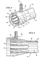
Figure 3 illustrates the dialyzer ofFigure 2 with the fiber bundle removed. -
Figure 4 illustrates a side elevation view of the dialyzer ofFigure 3 . -
Figure 5 illustrates a cross-sectional view of the dialyzer ofFigure 4 . - The present invention provides improved dialyzers and methods of using same. Although in the embodiment set forth below the dialyzer is designed for use in hemodialysis, it should be noted that the dialyzer can be used in a number of different therapies. In this regard, the dialyzer can be used in non-traditional hemodialysis methods. Such methods include, for example, regeneration and continuous flow therapies which may or may not include hemodialysis, for example, continuous flow peritoneal dialysis. Further, although the present invention, in an embodiment, can be utilized in methods of providing dialysis for patients having chronic kidney failure or disease, the present invention can be used for acute dialysis needs, for example, in an emergency room setting.
- Referring now to
Figure 1 , adialyzer 10 is generally illustrated. Thedialyzer 10 includes abody member 12 that generally comprises a casing. The casing includes acore section 14 as well as twobell members fiber bundle 20. - The
fiber bundle 20 includes a plurality of hollow fiber membranes. The membranes are semi-permeable having a selective permeability. The membranes are bundled together and assembled in the casing in a manner allowing blood to flow simultaneously in a parallel manner through the lumina of the fibers while a blood cleansing liquid (dialysate) is simultaneously passed through the casing. In theory, this allows the dialysate to bathe the exterior surface of the hollow fibers. A variety of compounds can be used to produce selective permeable membranes including polymers such as: cellulose; cellulose acetate; polyamide; polyacrylonitarile; polyvinyl alcohol; polymethacrylate; polysulfone; and polyolefin. Thefiber bundle 20 is encapsulated at each end of the dialyzer to prevent blood flow around the fibers. - Located at a first end of the dialyzer is a
fluid inlet 22 and at a second end afluid outlet 24 defined by afluid inlet header 26 and afluid outlet header 28. A variety of header designs can be utilized. In a preferred embodiment theinlet header 26 andoutlet header 28 have designs such as those set forth in US Patent Application publication No.US 2003/0075498A1 (U.S. Patent Application Serial No.09/871,863 - The
dialyzer body 10 also includes adialysate inlet 30 and adialysate outlet 32. In the preferred embodiment illustrated, thedialysate inlet 30 anddialysate outlet 32 define fluid flow channels that are in a radial direction, i.e., perpendicular to the fluid flow path of the blood. Thedialysate inlet 30 anddialysate outlet 32 are designed to allow dialysate to flow into an interior 34 of the dialyzer bathing the exterior surfaces of the fibers and thefiber bundle 20 and then out through theoutlet 32. This, as is known in the art, causes waste and other toxins to be removed from the blood through the semipermeable membrane of the fibers and carried away by the dialysate. - Pursuant to the present invention, an improved inlet and/or outlet design is provided. This provides for improved perfusion of the dialysate through the fiber bundle. In this regard, for a hollow fiber dialyzer to function optimally, three mass transfer resistances must be minimized. These mass transfer resistances include: 1) blood resistance; 2) membrane resistance; and 3) dialysate resistance. For a given fiber type and blood fow rate, the blood and membrane resistance are essentially fixed. The dialysate resistance, however, is dictated, in part, by the case design, fiber packing density, and effective shape of the fluid flow path.
- In a typical dialyzer, the bells and dialysate inlet and outlet, have straight walls that surround the hollow fiber. Experimental testing, set forth below, reveals the existence of dialysate shunts in such designs. That is, significant axial streams of dialysate flow between the outer surface of the fiber bundle and the core wall of the dialyzer. This results in an inefficient use of dialysate since fluid contact with blood carrying fibers is reduced. In addition, the residence time of the dialysate fluid in the core is short due to the increased flow velocity in these areas. Although experimentally it has been observed that a higher fiber packing density can reduce shunts, an increase in the fiber density makes it more difficult to perfuse dialysate into the center of the bundle.
- Set forth in Example 2 are computational fluid dynamic (CFD) studies. These studies demonstrate there is a variation in flow distribution across the diameter of a fiber bundle at various axial locations. It is clear that current designs do not provide sufficient fluid flow into the center of the bundle. This effect is most predominant near the bell/core junction of the case.
- The
dialysate inlet 30 anddialysate outlet 32 of the dialyzer of the present invention provide a design that reduces shunting. The design also improves dialysate perfusion into thebundle 20. In view of the designs of the present invention, the fiber ends do not deflect outwardly into the chamber of the larger inner diameter of the bell of the core as in prior art designs. Instead, structures are provided causing the outer fibers to be pulled away from the bundle. This provides improved access to the bundle core. - To this end, referring to
Figures 2-5 , the present invention provides an inletfluid flow channel 38 defined by anouter wall 40, aninner wall 42 and the top wall (not shown) defined by potting material that seals the fiber bundle, as is known in the art. Fluid flows from thedialysate inlet 30 into theinlet fluid channel 38. Theinlet fluid channel 34 preferably extends below and above thedialysate inlet 30. Thus, dialysate will enter theinlet fluid channel 34 through thedialysate inlet 30 and flow around the channel into the dialyzer. - As illustrated, the
outer wall 40 also defines the exterior of the casing of thedialyzer 10. As noted above, theinterior wall 42, with theouter wall 40, defines theinlet flow channel 38. The inner wall also includes a plurality of flutes, in the illustrated embodiment eightflutes flutes openings inlet flow channel 38 to enter an interior 34 of thedialyzer 10. - Due to the structure of the
flutes fiber bundle 20 is received within the semi-circular portion of each of the flutes. This causes thebundle 20 to separate below the potting material reducing the fiber density at an area right below the potting material. In addition, this design allows the openings of the flutes to extend into the potting material. Accordingly, dialysate is injected into the bundle as it is received within the inlet channel. - The space between the
outer wall 40 of thedialyzer 10 and theinner wall 42 that defines theflutes slots - Although, as illustrated, eight
flutes slots - Preferably, the outlet end 70 of
dialyzer 10 includes a structure similar to that of the dialysate inlet In this regard, thedialysate outlet 70 will include a dialysate outlet channel (not shown) similar to the dialysateinlet flow channel 38. However, this is not necessary and thedialysate outlet 70 can be of a standard bell structure as is known in the prior art. But, certain advantages are achieved by creating the dialysate outlet that is substantially identical to the dialysate inlet, including ease of manufacturing. - By way of example and not limitation, examples of the present invention will now be given.
- The following calculations illustrate the effect of dialysate shunts and blood and dialysate maldistributions on dialyzer clearance. Also, set forth below are estimates on the improvement in the clearance of existing dialyzers if the shunts and maldistributions could be eliminated.
- The clearance (CL) of a counterflow dialyzer is give by the following equations:

where - K = Overall mass transfer coefficient of the dialyzer for the solute of interest which consists of the mass transfer coefficients (the reciprocal of resistance) on the blood and dialysate sides of the membrane and that of the membrane itself; min/cm
- A = Area dialyzer, sq.cm.
- Qb = Blood flow rate, ml/min.
- Qd = Dialysate flow rate, ml/min
- If Qb = Qd
- CL = Qb(KA/Qb)/[(KA/Qb) + 1 ]
- These equations can be used to calculate the three mass transfer resistances of the standard dialyzers from measured urea clearances. The blood side resistance is 7.6 min/cm, the membrane resistance is 4.6 min/cm, and the dialysate side resistance is 6.4 min/cm.
- These equations can also be used to calculate the clearance of a dialyzer to illustrate the effect of shunts and maldistributions of the flows.
- If a portion of the dialysate flow does not pass through the fiber bundle of a hollow fiber dialyzer, but shunts between the bundle and the case, the clearance of the dialyzer will be reduced. For analysis purposes we assume that the dialysate flow rate in the above equations is reduced by the amount of the shunt.
- Tables 1 and 2 show the reduction in urea clearance with dialysate shunts for a 2.0 square meter and a 2.4 square meter dialyzer. The overall mass transfer coefficient has been adjusted downward to account for the lower dialysate side mass transfer coefficient due to the reduced effective dialysate flow caused by the shunt. It can be seen from these two tables that a large dialysate shunt can dramatically reduce the clearance of a dialyzer. Urea clearance as a function of percentage dialysate shunt for a 2.0 square meter dialyzer with 300 ml/min blood flow and 500 ml/min dialysate flow, is reduced from 269 ml/min to 229 ml/min by a 40% dialysate shunt. For a 2.4 square meter dialyzer, the clearance drops from 278 ml/min to 238 ml/min due to a 40% shunt.
- This analysis can also be used to predict the increase in clearance of a dialyzer if a shunt of known magnitude is eliminated. From a measured or calculated clearance value and an assumed shunt magnitude, the overall mass transfer coefficient of the dialyzer can be determined from the preceding equations. Using this calculated value of K and assuming the elimination of the assumed shunt, the improved clearance can be calculated. Table 3 shows the predicted urea clearances of 1.3, 1.6, 1.8 and 2.0 square meter dialyzers where 0%, 10%, 15 % and 20% shunt have been eliminated for a blood flow of 300 ml/min and dialysate flow rate of 500 ml/min.
- If the distribution of blood now through the fibers is not uniform and/or the distribution of dialysate flow through the fiber bundle is not uniform, the clearance of the dialyzer can suffer. Table 4 sets forth the results of four different maldistn-butions in a 2.0 square meter dialyzer.
- In Table 4, Line 1 provides the urea clearance of a dialyzer without maldistributions- Line 2 provides the urea clearance of a dialyzer with
blood flow 10% higher. Line 3 is the urea clearance with 10% lower blood flow. In a dialyzer where half the fibers have 10% higher blood flow and the other half have 10% lower blood flow, the clearance of this dialyzer will be the average of the clearances on lines 2 and 3 which is shown on line 4. For a 10% maldistribution of blood flow over the two halves of the dialyzer the urea clearance is only reduced from 268.8 to 267.6 ml/min., a minor reduction. - Lines 5, 6 and 7 of Table 4 set forth a 10% variation in dialysate flow that was added to the 10% blood flow variation with the higher blood flow occurring where the dialysate flow is lower (as what might occur near the center of the bundle). Here the urea clearance dropped further to 265.8 ml/min.
- On
lines 9 and 10, the dialysate maldistribution is increased to 20%. The urea clearance drops still further to 262,8 ml/min. - On
line - Using calculations similar to those of Table 4, a 20% maldistribution of both the blood and dialysate will result in a 12 ml/min reduction in clearance reduction in dialyzer clearance for a 2.0 square meter dialyzer at 300 ml/min blood flow and 500 ml/min dialysate flow that can be expected when flow maldistributions of either the blood or dialysate are corrected.
- Table 5 provides results similar to Table 4 for a 2.4 square meter dialyzer with a 10% blood maldistribution. Here it is seen that a 20% dialysate shunt reduces the clearance from 276.5 ml/min (line 4) to 271.3 ml/min (line 10).
- Table 6 provides similar results for 500ml/min blood flow and 800 ml/min dialysate flow. Here a 20% dialysate maldistribution results in a clearance reduction from 409.6 ml/min (line 4) to 402.7 ml/min (line 10).
- The preceding calculations illustrate that a dialysate shunt can significantly reduce the clearance of a dialyzer. Elimination of dialysate shunts will significantly increase the clearance of a dialyzer:
- These calculations also demonstrate that blood and dialysate flow maldistributions can reduce dialyzer clearance significantly. Elimination of flow maldistributions on either the blood side or dialysate side of a dialyzer will improve clearance values.
Table 1 Clearance with Dialysate Shunts Line Qb(ml/min) Qd(ml/min) Z=Qb/Qd K(nnn/cm) A (cm**2) Nt=KA/Qb CL(ml/min) Qb=200 1 200 500 0.400 0.056 20000 5.600 195.773 2 200 450 0.444 0.054 20000 5.400 194343 3 200 400 0.500 0.052 20000 5.200 192.286 4 200 350 0.571 0.05 20000 5.000 189.221 5 200 300 0.667 0.048 20000 4.800 184.447 6 200 250 0.800 0.046 20000 4.600 176.598 Qb=300 7 300 500 0.600 0.056 20000 3.733 268.847 8 300 450 0.667 0.054 20000 3.600 262.313 9 300 400 0.750 0.052 20000 3.467 253.959 10 300 350 0.857 0.05 20000 3.333 243.069 11 300 300 1.000 0.048 20000 3.200 228.571 Qb=400 12 400 500 0.800 0.056 20000 2.800 315.849 13 400 450 0.889 0.054 20000 2.700 303.585 14 400 400 1.000 0.052 20000 2.600 288.889 15 400 350 1.143 0.05 20000 2.500 271.063 16 400 300 1.333 0.048 20000 2.400 249.171 Qb=500 17 500 500 1.000 0.056 20000 2.240 345.679 18 500 450 1.111 0.054 20000 2.160 328.788 19 500 400 1.250 0.052 20000 2.080 309.300 20 500 350 1.429 0.05 20000 2.000 286.610 Table 2 Clearance with Dialysate Shunts Line Qb(ml/mm) Qd(ml/min) Z=Qb/Qd K(min/cm) A (cm**2) Nt=KA/Qb CL(ml/min) Qb=200 1 . 200 500 0.400 0.056 24000 6.720 197.856 2 200 450 0.444 0.054 24000 6.480 196.927 3 200 400 0.500 0.052 24000 6.240 195.485 4 200 350 0.571 0.05 24000 6.000 193.150 5 200 300 0.667 0.048 24000 5.760 189.167 6 200 250 0.800 0.046 24000 5.520 181.951 Qb=300 7 300 500 0.600 0.056 24000 4.480 277.784 8 300 450 0.667 0.054 24000 4.320 271.863 9 300 400 0.750 0.052 24000 4.160 263.929 10 300 350 0.857 0.05 24000 4.000 253.092 11 300 300 1.000 0.048 24000 3.840 238.017 Qb=400 12 400 500 0.800 0.056 24000 3.360 330.924 13 400 450 0.889 0.054 24000 3240 318.367 14 400 400 1.000 0.052 24000 3.120 302.913 15 400 350 1.143 0.05 24000 3.000 283.718 16 400 300 1.333 0.048 24000 2.880 259.714 Qb=500 17 500 800 0.625 0.056 24000 2.688 411.352 18 500 720 0.694 0.054 24000 2.592 399.048 19 500 640 0.781 0.052 24000 2.496 384.270 20 500 560 0.893 0.05 24000 2.400 366.196 Table 3 INCREASE IN CLEARANCE WITH ELIMINATION OF 10%,15% AND 20% DIALYSATE SHUNT Qb Qd Kurea A Nt Z CLurea Shunt 300 500 0.054 13000 2329 0.6 238.104 0% 300 500 0.057 13000 2.472 0.6 242.527 10% 300 500 0.059 13000 2.569 0.6 245.322 15% 300 500 0.062 13000 2.691 0.6 248.592 20% 300 500 0.054 16000 2.867 0.6 252.898 0% 300 500 0.058 16000 3.083 0.6 257.625 10% 300 500 0.061 16000 3.227 0.6 260.465 15% 300 500 0.064 16000 3.410 0.6 263.773 20% 300 500 0.054 18000 3.225 0.6 260.432 0% 300 500 0.058 18000 3.458 0.6 264.578 10% 300 500 0.061 18000 3.634 0.6 267375 15% 300 500 0.064 18000 3.860 0.6 270.616 20% 300 500 0.054 20000 3.583 0.6 266.598 0% 300 500 0.059 20000 3.923 0.6 271.442 10% 300 500 0.062 20000 4.140 0.6 274.134 15% 300 500 0.066 20000 4.425 0.6 277.230 20% Table 4 ANALYSIS OF BLOOD AND DIALYSATE FLOW DISTRIBUTION VARIATIONS Line Qb(ml/min) Qd(ml/min) Z=Qb/Qd K(min/cm) A (cm**2) Nt=KA/Qb CL(ml/min) 10% Qb variation, Qd uniform 1 300 500 0.600 0.056 20000 3.733 268.847 2 330 500 0.660 0.056 20000 3.394 285.311 3 270 500 0.540 0.056 20000 4.148 249.970 4 AVERAGE 267.640 10% Qb variation, 10% Qd variation, Qb max where Qd min. 5 330 450 0.733 0.056 20000 3.394 279388 6 270 550 0.491 0.056 20000 4.148 252.314 7 AVERAGE 265.851 10% Qb variation, 20% Qd variation, Qb max where Qd min. 8 330 400 0.825 0.056 20000 3.394 271.436 9 270 600 0.450 0.056 20000 4.148 254.103 10 AVERAGE 262.770 10% Qb variation, 10% Qd variation, Qb max. where Qd max. 11 300 500 0.600 0.056 20000 3.733 268.847 12 330 550 0.600 0.056 20000 3.394 289.839 13 270 450 0.600 0.056 20000 4.148 246.801 14 AVERAGE 268.320 Table 5 ANALYSIS OF BLOOD AND DIALYSATE FLOW DISTRIBUTION VARIATIONS Line Qb(ml/min) Qd(ml/min) Z=Qb/Qd K(min/cm) A (cm**2) Nt=KA/Qb CL(ml/min) 10% Qb variation, Qd uniform 1 300 500 0.600 0.056 24000 4.480 277.784 2 330 500 0.660 0.056 24000 4.073 296.344 3 270 500 0.540 0.056 24000 4.978 256.692 4 AVERAGE 276.518 10% Qb variation, 10% Qd variation, Qb max where Qd min. 5 330 450 0.733 0.056 24000 4.073 290.525 6 270. 550 0.491 0.056 24000 4.978 258.654 7 AVERAGE 274.589 10% Qb variation, 20% Qd variation, Qb max where Qd min. 8 330 400 0.825 0.056 24000 4.073 282.451 9 270 600 0.450 0.056 24000 4.978 260.102 10 AVERAGE 271.277 10% Qb variation, 10% Qd variation, Qb max. where Qd max. 11 300 500 0.600 0.056 24000 4.480 277.784 12 330 550 0.600 0.056 24000 4.073 300.662 13 270 450 0.600 0.056 24000 4.978 253.937 14 AVERAGE 277300 Table 6 ANALYSIS OF BLOOD AND DIALYSATE FLOW DISTRIBUTION VARIATIONS Line Qb(ml/min) Qd(ml/min) Z=Qb/Qd K(min/cm) A (cm**2) Nt=KA/Qb CL(ml/min) 10% Qb variation, Qd uniform 1 500 800 0.625 0.056 24000 2.688 411352 2 550 800 0.688 0.056 24000 2.444 432.162 3 450 800 0.563 0.056 24000 2.987 387.128 4 AVERAGE 409.645 10% Qb variation, 10% Qd variation, Qb max where Qd min. 5 550 720 0.764 0.056 24000 2.444 422.278 6 450 880 0.511 0.056 24000 2.987 392.013 7 AVERAGE 407.145 10% Qb variation, 20% Qd variation, Qb max where Qd min. 8 550 640 0.859 0.056 24000 2.444 409.551 9 450 960 0.469 0.056 24000 2.987 395.897 10 AVERAGE 402.724 10% Qb variation, 10% Qd variation, Qb max. where Qd max. 11 500 800 0.625 0.056 24000 2.688 411.352 12 550 880 0.625 0.056 24000 2.444 440.011 13 450 720 0.625 0.056 24000 2.987 380.836 14 AVERAGE 410.423 - A computational fluid dynamics (CFD) analysis was performed for the blood and dialysate flow transport phenomena occurring in dialyzers of various designs. This experiment assumed that there is no mass-transfer (ultra-filtration) between the blood and the dialysate flows through the porous fiber wall. The two flow fields were analyzed separately. Several different housing variations and header designs were considered. A porous medium model was used to simulate the flow in the fiber bundle. The flow permeability for the fiber-bundle was computed from a CFD model.
- This study concluded that in general the blood flow distributions in the fiber-bundle are fairly uniform. But a flow stagnant region usually exists in the inlet header. A flattened header design can greatly reduce the flow stagnant region.
- The dialysate flow distributions are quite non-uniform for the regions adjacent to the flow inlet and outlet However, the distributions of dialysate flow for the dialyzer header designs of the present invention are more uniform than the conventional dialyzer.
- There are thousands of fibers in a dialyzer. It is not feasible to solve for the detailed flow distribution around each fiber. A porous medium model is used here for modeling the over-all flow and pressure distributions in the fiber-bundle. The model assumes that there is a local balance between pressure and resistance forces in the flow domain such that:

where (i=1,2,3) represents the orthotropic directions (three mutually orthogonal principal axes with differing material properties or conditions). Kj is the permeability and Ui is the superficial velocity in direction ξi. (The volume flow rate divided by the total cross-sectional area.) The permeability Ki is computed by the following equation:
where αi and βi are constants for a particular flow, Û is the superficial velocity vector. It is noted that the permeability in Darcy's law is defined as:
where κ; is the permeability and is equal to µ/Ki. - The flow in the dialyzer is assumed to be laminar, steady state, incompressible, and Newtonian. The permeability for the porous-medium flow model should be derived from the flow pressure drop in the fiber-bundle measured experimentally. However, the experimental data are not available. The other alternative is to solve for the pressure distributions numerically. First it is assumed that the fibers are arranged in a fixed staggered pattern. The space in between the fibers is computed from the given fiber packing factor.
- The blood flow in a dialyzer is inside the hollow fibers. The porous medium flow permeability along the axial-direction is computed based on the pressure drop for a fully developed laminar pipe flow. The permeability is infinite for cross flow.
- For the dialysate flow outside the fibers, the pressure drop is computed numerically for flow in several layers of fibers. Then the flow permeability is calculated from the computed pressure gradient for the particular fiber configuration. The axial flow pressure drop is different from the cross-flow pressure drop and the flow in each direction is computed separately.
- It is noted that the porous medium model is only an approximation for the actual complicated flow problem. The fiber distributions in a dialyzer are usually non-uniform and the flow permeability varies spatially.
- In this study, two dialyzer designs were analyzed. The first is an elongated version of the prior art dialyzer and the second is the present invention dialyzer. The input parameters for both cases are presented in Table 7.
- In the elongated prior art dialyzer, dialysate is introduced to the bundle in the inlet bell, where all the fibers along the bundle perimeter are exposed. In one embodiment of the present invention dialyzer, there are eight slots in the inlet bell region through which dialysate is introduced to adjacent sections of the fiber bundle. The width and length of the slots are 0.8mm (0.031") and 1·5mm (0.294"), respectively. The bell configurations for the opposite (outlet) end of each dialyzer are the same as the respective inlets.
- The output values are presented in Table 8. For the elongated present art dialyzer, it is seen that the dialysate flow velocity is not very uniform adjacent to the flow inlet and outlet and there is a 50% difference between the maximum and the minimum values. The velocity profiles are more uniform in the mid-section of the bundle, with about a 2% difference between the maximum and minimum values.
- For the present invention dialyzer at a dialysate flow rate of 500 ml/min, the dialysate flow velocity is uniform adjacent to the flow inlet and outlet showing a 6% , difference between the maximum and the minimum values. In the mid-section of the bundle, there exists a 0-5% flow variation. Flow characteristics for this dialyzer are also shown for a dialysate Bow rate of 1000 ml/min.
- This study has shown that the dialysate flow in the present invention dialyzer is more uniform than in the elongated prior art dialyzer. This is especially true for the flow adjacent to the dialysate inlet and outlet.
Table 7 Input parameters for various runs(dialysate side) Run Name Elongated Prior Art Dialyzer Present Invention Dialyzer Fiber parameters ID (µm) 200 200 OD(µm) 260 260 Wall thickness (µm) 30 30 Number of fibers 11,200 11,200 Effective fiber length(cm) 32.6 31.55 Dialyzer surface area (m2) 2.3 2.3 Fiber packing factor Straight section 0.483 0.537 Bell 0.483 0.306 Permeability Parallel flow (kg/m 3s) 8.348×10⁶ 8.348×10⁶ Cross flow (kg/m3s) Infinite Infinite Dialysate parameters Qd (ml/min) 500 500 1000 Porosity Straight section 0.517 0.463 Bell 0.517 0.694 Dialysate viscosity (cp) 1 1 Dialysate density (kg/m3) 1000 1000 Permeability (kg/m3s) Straight section (cross-flow) 9.65x10⁵ 2.51x10⁶ Bell (cross-flow) 9.65x10⁵ 6.02x10⁵ Straight section (parallel flow) 1.37x10⁶ 2.25x10⁶ Bell (parallel flow) 137x106 1.45 x10⁶ Table 8 Output values for various runs (dialysate side) Run Name Elongated prior art dialyzer Present invention dialyzer Qd (ml/min) 500 500 1000 Pressure drop (mmHg) 20.1 45.78 92.55 Maximum shear rate (1/s) 1407 Maximum % flow maldistribution Near inlet 50 6 0.7 Midplane 2 0.5 0.8 Near outlet 50 4 1.1 - It should be understood that various changes and modifications to the presently preferred embodiments described herein will be apparent to those skilled in the art. Such changes and modifications can be made without departing from the scope of the present invention and without diminishing its intended advantages. It is therefore intended that such changes and modifications be covered by the appended claims.
Claims (20)
- A dialyzer (10) having a fluid inlet (22) and a fluid outlet (24) comprising:a casing (12) defining an interior and including a dialysate inlet (30) and a dialysate outlet (32) wherein the casing (12) is in fluid communication with the fluid inlet (22) and the fluid outlet (24);a plurality of fibres located in the interior of the casing (12) and defining a fibre bundle (20); anda dialysate inlet fluid channel (38) in fluid communication with the dialysate inlet (30) and including a plurality of flutes (50) that extend into a portion of the fibre bundle (20), the flutes (50) defining an opening (51) for allowing dialysate to flow from the inlet fluid channel (38) into the interior of the casing (12).
- The dialyzer (10) of Claim 1 including a dialysate outlet fluid channel in fluid communication with the dialysate outlet (32) and including a plurality of flutes (50) that extend into a portion of the fibre bundle (20), the flutes (50) defining openings (51) for allowing dialysate to flow from the interior of the casing (12) into the dialysate outlet fluid channel.
- The dialyzer (10) of Claim 2 wherein the outlet fluid channel and inlet fluid channel (38) have substantially the same structure.
- The dialyzer (10) of Claim 1 wherein the casing (12) is constructed from plastic.
- The dialyzer (10) of Claim 1 including eight flutes (50, 52, 54, 56, 58, 60, 62, 64).
- The dialyzer (10) of Claim 1 wherein a top portion of the dialysate inlet fluid channel (38) is defined by potting material.
- The dialyzer (10) of Claim 1 wherein the flutes (50) circumscribe an entire circumference of a first end of the dialyzer (10).
- The dialyzer of Claim 1 wherein the opening (51) in the flutes (50) is a slot.
- The dialyzer of Claim 8 wherein each flute (30) defines a separate opening (51)..
- A dialyzer (10) according to Claim 1 wherein the casing (12) has a first end having the dialysate inlet (30) and a second end having the dialysate outlet (32), and
the fibre bundle (20) extends from the first end to the second end; and
the dialysate inlet fluid channel (38) is defined in part by a portion of the casing (12) that defines an exterior surface of the first end and an inner wall that circumscribes a portion of the interior, the inner wall including the plurality of flutes (50); and
a fluid outlet channel in fluid communication with the dialysate outlet (32), the fluid outlet channel being defined in part by a portion of the casing (12) that defines an exterior surface of the second end and an inner wall that circumscribes a portion of the interior, the inner wall including portions that extend into the fibre bundle (20), at least one of the portions including an aperture (51) for allowing fluid to flow from the interior into the fluid outlet channel. - The dialyzer (10) of Claim 10, wherein the inner wall defines a plurality of semicircular structures (50).
- The dialyzer (10) of Claim 10 wherein the outlet fluid channel and inlet fluid channel (38) have substantially the same structure.
- The dialyzer (10) of Claim 10 wherein a top portion of the fluid inlet channel (3 8) is defined by potting material.
- The dialyzer (10) of Claim 10 wherein the aperture (51) is a slot.
- The dialyzer (10) of Claim 10 wherein the fluid inlet channel (38) and fluid outlet channel includes at least six separate portions (50) that extend into the fibre bundle each including an aperture (51).
- A dialyzer (10) according to Claim 1 wherein the casing (12) has a first end having the dialysate inlet (30) and a second end having the dialysate outlet (32); and
the dialysate inlet fluid channel (38) is defined, at least in part, by an interior wall of the casing (12), a potting material and an inner wall circumscribing the interior of the first end and including a plurality of members defining areas for receiving fibres of the fibre bundle (20) and a portion that extends into the fibre bundle (20), each of the portions (50) defining the flutes (50). - The dialyzer (10) of Claim 16 wherein the second end includes a dialysate outlet fluid channel including a plurality of flutes (50) that extend into a portion of the fibre bundle (20), the flutes (50) including openings (51) for allowing dialysate to flow from the interior of the casing (12) into the dialysate outlet fluid channel.
- The dialyzer (10) of Claim 17 wherein the outlet fluid channel and inlet fluid channel (38) have substantially the same structure.
- The dialyzer (10) of Claim 16 including eight flutes (50, 52, 54, 56, 58, 60, 62,64).
- The dialyzer (10) of Claim 16 wherein the opening (51) in the flutes (50) is a slot.
Applications Claiming Priority (3)
| Application Number | Priority Date | Filing Date | Title |
|---|---|---|---|
| US871864 | 1992-04-20 | ||
| US09/871,864 US6623638B2 (en) | 2001-06-01 | 2001-06-01 | Hemodialyzer having improved dialysate perfusion |
| PCT/US2002/013043 WO2002098490A1 (en) | 2001-06-01 | 2002-04-24 | Hemodialyzer having improved dialysate perfusion |
Publications (2)
| Publication Number | Publication Date |
|---|---|
| EP1406685A1 EP1406685A1 (en) | 2004-04-14 |
| EP1406685B1 true EP1406685B1 (en) | 2008-06-11 |
Family
ID=25358329
Family Applications (1)
| Application Number | Title | Priority Date | Filing Date |
|---|---|---|---|
| EP02776553A Expired - Lifetime EP1406685B1 (en) | 2001-06-01 | 2002-04-24 | Hemodialyzer having improved dialysate perfusion |
Country Status (9)
| Country | Link |
|---|---|
| US (1) | US6623638B2 (en) |
| EP (1) | EP1406685B1 (en) |
| JP (2) | JP4036828B2 (en) |
| AR (1) | AR033170A1 (en) |
| AT (1) | ATE397946T1 (en) |
| DE (1) | DE60227076D1 (en) |
| MX (1) | MXPA03010988A (en) |
| TW (1) | TW553751B (en) |
| WO (1) | WO2002098490A1 (en) |
Cited By (23)
| Publication number | Priority date | Publication date | Assignee | Title |
|---|---|---|---|---|
| US8425455B2 (en) | 2010-03-30 | 2013-04-23 | Angiodynamics, Inc. | Bronchial catheter and method of use |
| US9598691B2 (en) | 2008-04-29 | 2017-03-21 | Virginia Tech Intellectual Properties, Inc. | Irreversible electroporation to create tissue scaffolds |
| US9867652B2 (en) | 2008-04-29 | 2018-01-16 | Virginia Tech Intellectual Properties, Inc. | Irreversible electroporation using tissue vasculature to treat aberrant cell masses or create tissue scaffolds |
| US10117707B2 (en) | 2008-04-29 | 2018-11-06 | Virginia Tech Intellectual Properties, Inc. | System and method for estimating tissue heating of a target ablation zone for electrical-energy based therapies |
| US10154874B2 (en) | 2008-04-29 | 2018-12-18 | Virginia Tech Intellectual Properties, Inc. | Immunotherapeutic methods using irreversible electroporation |
| US10238447B2 (en) | 2008-04-29 | 2019-03-26 | Virginia Tech Intellectual Properties, Inc. | System and method for ablating a tissue site by electroporation with real-time monitoring of treatment progress |
| US10245105B2 (en) | 2008-04-29 | 2019-04-02 | Virginia Tech Intellectual Properties, Inc. | Electroporation with cooling to treat tissue |
| US10272178B2 (en) | 2008-04-29 | 2019-04-30 | Virginia Tech Intellectual Properties Inc. | Methods for blood-brain barrier disruption using electrical energy |
| US10292755B2 (en) | 2009-04-09 | 2019-05-21 | Virginia Tech Intellectual Properties, Inc. | High frequency electroporation for cancer therapy |
| US10470822B2 (en) | 2008-04-29 | 2019-11-12 | Virginia Tech Intellectual Properties, Inc. | System and method for estimating a treatment volume for administering electrical-energy based therapies |
| US10471254B2 (en) | 2014-05-12 | 2019-11-12 | Virginia Tech Intellectual Properties, Inc. | Selective modulation of intracellular effects of cells using pulsed electric fields |
| US10694972B2 (en) | 2014-12-15 | 2020-06-30 | Virginia Tech Intellectual Properties, Inc. | Devices, systems, and methods for real-time monitoring of electrophysical effects during tissue treatment |
| US10702326B2 (en) | 2011-07-15 | 2020-07-07 | Virginia Tech Intellectual Properties, Inc. | Device and method for electroporation based treatment of stenosis of a tubular body part |
| US11254926B2 (en) | 2008-04-29 | 2022-02-22 | Virginia Tech Intellectual Properties, Inc. | Devices and methods for high frequency electroporation |
| US11272979B2 (en) | 2008-04-29 | 2022-03-15 | Virginia Tech Intellectual Properties, Inc. | System and method for estimating tissue heating of a target ablation zone for electrical-energy based therapies |
| US11311329B2 (en) | 2018-03-13 | 2022-04-26 | Virginia Tech Intellectual Properties, Inc. | Treatment planning for immunotherapy based treatments using non-thermal ablation techniques |
| US11382681B2 (en) | 2009-04-09 | 2022-07-12 | Virginia Tech Intellectual Properties, Inc. | Device and methods for delivery of high frequency electrical pulses for non-thermal ablation |
| US11453873B2 (en) | 2008-04-29 | 2022-09-27 | Virginia Tech Intellectual Properties, Inc. | Methods for delivery of biphasic electrical pulses for non-thermal ablation |
| US11607537B2 (en) | 2017-12-05 | 2023-03-21 | Virginia Tech Intellectual Properties, Inc. | Method for treating neurological disorders, including tumors, with electroporation |
| US11638603B2 (en) | 2009-04-09 | 2023-05-02 | Virginia Tech Intellectual Properties, Inc. | Selective modulation of intracellular effects of cells using pulsed electric fields |
| US11925405B2 (en) | 2018-03-13 | 2024-03-12 | Virginia Tech Intellectual Properties, Inc. | Treatment planning system for immunotherapy enhancement via non-thermal ablation |
| US11950835B2 (en) | 2019-06-28 | 2024-04-09 | Virginia Tech Intellectual Properties, Inc. | Cycled pulsing to mitigate thermal damage for multi-electrode irreversible electroporation therapy |
| US11957405B2 (en) | 2020-10-16 | 2024-04-16 | Angiodynamics, Inc. | Methods of sterilization and treating infection using irreversible electroporation |
Families Citing this family (32)
| Publication number | Priority date | Publication date | Assignee | Title |
|---|---|---|---|---|
| US20040254513A1 (en) | 2002-04-10 | 2004-12-16 | Sherwin Shang | Conductive polymer materials and applications thereof including monitoring and providing effective therapy |
| US7052480B2 (en) | 2002-04-10 | 2006-05-30 | Baxter International Inc. | Access disconnection systems and methods |
| US10155082B2 (en) | 2002-04-10 | 2018-12-18 | Baxter International Inc. | Enhanced signal detection for access disconnection systems |
| US7022098B2 (en) | 2002-04-10 | 2006-04-04 | Baxter International Inc. | Access disconnection systems and methods |
| CA2575731C (en) | 2003-12-24 | 2014-07-15 | Chemica Technologies, Inc. | Dialysate regeneration system for portable human dialysis |
| US9254279B2 (en) * | 2004-05-12 | 2016-02-09 | Baxter International Inc. | Nitric oxide scavengers |
| US7534349B2 (en) * | 2005-09-02 | 2009-05-19 | Nephros, Inc. | Dual stage ultrafilter devices in the form of portable filter devices, shower devices, and hydration packs |
| US7775375B2 (en) * | 2005-11-03 | 2010-08-17 | Medica S.R.L. | Redundant ultrafiltration device |
| WO2007138659A1 (en) | 2006-05-26 | 2007-12-06 | National University Corporation Nagoya University | External fixator |
| US20100125235A1 (en) * | 2008-06-16 | 2010-05-20 | Triaxis Medical Devices, Inc. | Blood Treatment Apparatus Having Branched Flow Distribution |
| BRPI0916763B8 (en) * | 2008-07-15 | 2021-06-22 | Mirimedical Llc | dialyzer |
| US8114043B2 (en) | 2008-07-25 | 2012-02-14 | Baxter International Inc. | Electromagnetic induction access disconnect sensor |
| US8903488B2 (en) | 2009-05-28 | 2014-12-02 | Angiodynamics, Inc. | System and method for synchronizing energy delivery to the cardiac rhythm |
| US9895189B2 (en) | 2009-06-19 | 2018-02-20 | Angiodynamics, Inc. | Methods of sterilization and treating infection using irreversible electroporation |
| US8388566B2 (en) | 2010-04-29 | 2013-03-05 | Sorin Group Italia, S.r.l. | Oxygenator with integrated arterial filter including filter frame |
| EP2612685B1 (en) | 2010-08-19 | 2014-10-08 | Sorin Group Italia S.r.l. | Blood processing unit with modified flow path |
| EP2524712B1 (en) | 2011-05-17 | 2018-12-12 | Sorin Group Italia S.r.l. | Blood processing unit with cross blood flow |
| US9700368B2 (en) | 2010-10-13 | 2017-07-11 | Angiodynamics, Inc. | System and method for electrically ablating tissue of a patient |
| US9078665B2 (en) | 2011-09-28 | 2015-07-14 | Angiodynamics, Inc. | Multiple treatment zone ablation probe |
| US9888956B2 (en) | 2013-01-22 | 2018-02-13 | Angiodynamics, Inc. | Integrated pump and generator device and method of use |
| JP6297706B2 (en) | 2014-01-09 | 2018-03-20 | ソリン・グループ・イタリア・ソシエタ・ア・レスポンサビリタ・リミタータSorin Group Italia S.r.l. | Blood processing unit having a heat exchanger core forming a modified flow path |
| JP6386580B2 (en) | 2014-02-28 | 2018-09-05 | ソリン・グループ・イタリア・ソシエタ・ア・レスポンサビリタ・リミタータSorin Group Italia S.r.l. | System for providing an arterial filter integrated with an oxygenator that minimizes the additional fill volume |
| US10369263B2 (en) | 2014-03-29 | 2019-08-06 | Novaflux Inc. | Blood processing cartridges and systems, and methods for extracorporeal blood therapies |
| DE102014108230A1 (en) | 2014-06-12 | 2015-12-17 | B. Braun Avitum Ag | Dialyzer with a bundle of hollow fibers and method for producing such a hollow fiber |
| US10814056B2 (en) | 2014-11-12 | 2020-10-27 | Sorin Group Italia S.R.L. | Elastic protection tube for a hollow fiber blood processing apparatus |
| JP6535108B2 (en) | 2015-05-12 | 2019-06-26 | ソリン・グループ・イタリア・ソシエタ・ア・レスポンサビリタ・リミタータSorin Group Italia S.r.l. | Blood gas exchanger with one or more limiting elements for reducing gas exchange |
| US10426884B2 (en) | 2015-06-26 | 2019-10-01 | Novaflux Inc. | Cartridges and systems for outside-in flow in membrane-based therapies |
| EP3352888B8 (en) | 2015-09-24 | 2022-01-12 | Princeton Trade and Technology Inc. | Cartridges for hollow fibre membrane-based therapies |
| CN105343954B (en) * | 2015-09-25 | 2018-03-06 | 珠海健帆生物科技股份有限公司 | Compound apparatus for purifying blood and preparation method thereof |
| TW201806631A (en) * | 2016-08-19 | 2018-03-01 | 施顯章 | Hemodialysis device |
| EP3290100B1 (en) * | 2016-08-31 | 2020-08-19 | Gambro Lundia AB | Diffusion and/or filtration device |
| US10905492B2 (en) | 2016-11-17 | 2021-02-02 | Angiodynamics, Inc. | Techniques for irreversible electroporation using a single-pole tine-style internal device communicating with an external surface electrode |
Family Cites Families (42)
| Publication number | Priority date | Publication date | Assignee | Title |
|---|---|---|---|---|
| US4202776A (en) | 1975-07-28 | 1980-05-13 | Nippon Zeon Co., Ltd. | Hollow-fiber permeability apparatus |
| US4219426A (en) | 1976-03-19 | 1980-08-26 | Organon Teknika B.V. | Dialysis device |
| JPS5322163A (en) | 1976-08-12 | 1978-03-01 | Nippon Zeon Co Ltd | Mass transfer apparatus of hollow fiber type |
| DE2646358C2 (en) | 1976-10-14 | 1982-05-13 | Dr. Eduard Fresenius, Chemisch-pharmazeutische Industrie KG Apparatebau KG, 6380 Bad Homburg | Hollow fiber dialyzer |
| FR2374932A1 (en) | 1976-12-24 | 1978-07-21 | Rhone Poulenc Ind | HOLLOW FIBER APPARATUS, USABLE IN PARTICULAR AS AN ARTIFICIAL KIDNEY |
| US4201673A (en) | 1977-07-04 | 1980-05-06 | Terumo Corporation | Apparatus for dialysis of solution |
| US4220535A (en) | 1978-08-04 | 1980-09-02 | Monsanto Company | Multi-zoned hollow fiber permeator |
| DE2839937A1 (en) | 1978-09-14 | 1980-04-03 | Sigdell Jan Erik Dr | Hollow fibre dialyser - having hollow fibres laid in support grooves which can be wound round support core to give good blood distribution over fibres |
| US4396510A (en) * | 1981-01-08 | 1983-08-02 | Bio-Med Corporation | Mass transfer device |
| US4572724A (en) | 1984-04-12 | 1986-02-25 | Pall Corporation | Blood filter |
| CA1251109A (en) | 1984-04-24 | 1989-03-14 | Tohru Takemura | Blood oxygenator using a hollow-fiber membrane |
| US5192478A (en) | 1984-10-22 | 1993-03-09 | The Dow Chemical Company | Method of forming tubesheet for hollow fibers |
| DE8527694U1 (en) | 1985-04-27 | 1987-02-19 | Akzo Gmbh, 5600 Wuppertal, De | |
| US4876012A (en) | 1986-09-12 | 1989-10-24 | Memtec Limited | Hollow fibre filter cartridge and header |
| SE454847B (en) | 1987-08-31 | 1988-06-06 | Gambro Dialysatoren | DEVICE FOR DIFFUSION AND / OR FILTERING AND PROCEDURE FOR MANUFACTURING THIS DEVICE |
| JPH01148266A (en) | 1987-12-04 | 1989-06-09 | Terumo Corp | Blood filter |
| JPH0696098B2 (en) | 1988-05-27 | 1994-11-30 | 株式会社クラレ | Hollow fiber type fluid treatment equipment |
| US5139741A (en) | 1988-12-29 | 1992-08-18 | Terumo Kabushiki Kaisha | Blood processing apparatus of hollow fiber type |
| JPH0614965B2 (en) | 1989-01-10 | 1994-03-02 | テルモ株式会社 | Oxygenator |
| JPH0394928A (en) * | 1989-09-06 | 1991-04-19 | Mitsubishi Heavy Ind Ltd | Method for controlling synchronization between rotary perforating tools |
| EP0452902A3 (en) | 1990-04-18 | 1992-02-26 | Terumo Kabushiki Kaisha | Hollow fiber type liquid processing apparatus |
| IT1240692B (en) | 1990-05-02 | 1993-12-17 | Dideco Spa | BLOOD FILTER IN MEDICAL EQUIPMENT |
| FR2672513B1 (en) | 1991-02-13 | 1994-03-18 | Tech Sep | IMPROVED METHOD AND MODULE FOR FILTERING IN A LIQUID MEDIUM UNDER INSTANTANEOUS TANGENTIAL FLOW. |
| US5264171A (en) | 1991-12-31 | 1993-11-23 | Hoechst Celanese Corporation | Method of making spiral-wound hollow fiber membrane fabric cartridges and modules having flow-directing baffles |
| US5919369A (en) | 1992-02-06 | 1999-07-06 | Hemocleanse, Inc. | Hemofiltration and plasmafiltration devices and methods |
| WO1994003266A1 (en) | 1992-08-03 | 1994-02-17 | Maloney James V Jr | Improved mass and thermal transfer means for use in heart lung machines, dialyzers, and other applications |
| GB2276566A (en) | 1993-03-24 | 1994-10-05 | Saitekku Kabushiki Kaisha | Haemodialyser unit |
| US5618425A (en) | 1993-04-30 | 1997-04-08 | Terumo Kabushiki Kaisha | Filtering apparatus with a pleated filtering element embedded in a filling material |
| US5346621A (en) | 1993-05-19 | 1994-09-13 | Avecor Cardiovascular, Inc. | Hollow fiber blood oxygenator |
| US5798041A (en) | 1995-09-06 | 1998-08-25 | Hemasure, Inc. | In-line liquid filtration device useable for blood, blood products or the like |
| US5632894A (en) | 1994-06-24 | 1997-05-27 | Gish Biomedical, Inc. | Arterial blood filter with upwardly inclining delivery inlet conduit |
| US5626759A (en) | 1994-08-01 | 1997-05-06 | Regents Of The University Of Colorado | Blood treatment device with moving membrane |
| EP0701826B1 (en) | 1994-09-02 | 2000-03-22 | Terumo Kabushiki Kaisha | Dialyzer |
| US5500134A (en) | 1995-03-16 | 1996-03-19 | Dyna Flow, Inc. | Microfiltration system with swirling flow around filter medium |
| US5525144A (en) | 1995-04-20 | 1996-06-11 | A/G Technology Corporation | Tangential flow filtering and separating |
| US5651765A (en) | 1995-04-27 | 1997-07-29 | Avecor Cardiovascular Inc. | Blood filter with concentric pleats and method of use |
| EP0765683B1 (en) | 1995-09-25 | 1998-07-01 | MEDOS Medizintechnik GmbH | Device for treating liquids, in particular blood |
| JP3574902B2 (en) | 1996-11-15 | 2004-10-06 | サイテック株式会社 | Hollow fiber type dialyzer |
| US6074559A (en) | 1996-11-21 | 2000-06-13 | Fresenius Medical Care Deutschland Gmbh | Filter device having a hollow fiber bundle and associated sealing devices |
| JP4115626B2 (en) | 1998-05-25 | 2008-07-09 | 旭化成クラレメディカル株式会社 | Method for producing hollow fiber membrane hemodialyzer |
| US6113782A (en) | 1998-07-28 | 2000-09-05 | Terumo Cardiovascular Systems Corporation | Potting of tubular bundles in housing |
| US6176904B1 (en) | 1999-07-02 | 2001-01-23 | Brij M. Gupta | Blood filter |
-
2001
- 2001-06-01 US US09/871,864 patent/US6623638B2/en not_active Expired - Lifetime
-
2002
- 2002-04-24 AT AT02776553T patent/ATE397946T1/en not_active IP Right Cessation
- 2002-04-24 EP EP02776553A patent/EP1406685B1/en not_active Expired - Lifetime
- 2002-04-24 JP JP2003501527A patent/JP4036828B2/en not_active Expired - Fee Related
- 2002-04-24 WO PCT/US2002/013043 patent/WO2002098490A1/en active Application Filing
- 2002-04-24 MX MXPA03010988A patent/MXPA03010988A/en active IP Right Grant
- 2002-04-24 DE DE60227076T patent/DE60227076D1/en not_active Expired - Lifetime
- 2002-04-29 AR ARP020101578A patent/AR033170A1/en not_active Application Discontinuation
- 2002-05-02 TW TW091109115A patent/TW553751B/en not_active IP Right Cessation
-
2007
- 2007-09-19 JP JP2007242902A patent/JP2008029857A/en active Pending
Cited By (36)
| Publication number | Priority date | Publication date | Assignee | Title |
|---|---|---|---|---|
| US10959772B2 (en) | 2008-04-29 | 2021-03-30 | Virginia Tech Intellectual Properties, Inc. | Blood-brain barrier disruption using electrical energy |
| US10117707B2 (en) | 2008-04-29 | 2018-11-06 | Virginia Tech Intellectual Properties, Inc. | System and method for estimating tissue heating of a target ablation zone for electrical-energy based therapies |
| US10828086B2 (en) | 2008-04-29 | 2020-11-10 | Virginia Tech Intellectual Properties, Inc. | Immunotherapeutic methods using irreversible electroporation |
| US10828085B2 (en) | 2008-04-29 | 2020-11-10 | Virginia Tech Intellectual Properties, Inc. | Immunotherapeutic methods using irreversible electroporation |
| US10154874B2 (en) | 2008-04-29 | 2018-12-18 | Virginia Tech Intellectual Properties, Inc. | Immunotherapeutic methods using irreversible electroporation |
| US10238447B2 (en) | 2008-04-29 | 2019-03-26 | Virginia Tech Intellectual Properties, Inc. | System and method for ablating a tissue site by electroporation with real-time monitoring of treatment progress |
| US10245105B2 (en) | 2008-04-29 | 2019-04-02 | Virginia Tech Intellectual Properties, Inc. | Electroporation with cooling to treat tissue |
| US10245098B2 (en) | 2008-04-29 | 2019-04-02 | Virginia Tech Intellectual Properties, Inc. | Acute blood-brain barrier disruption using electrical energy based therapy |
| US10272178B2 (en) | 2008-04-29 | 2019-04-30 | Virginia Tech Intellectual Properties Inc. | Methods for blood-brain barrier disruption using electrical energy |
| US10286108B2 (en) | 2008-04-29 | 2019-05-14 | Virginia Tech Intellectual Properties, Inc. | Irreversible electroporation to create tissue scaffolds |
| US11952568B2 (en) | 2008-04-29 | 2024-04-09 | Virginia Tech Intellectual Properties, Inc. | Device and methods for delivery of biphasic electrical pulses for non-thermal ablation |
| US10470822B2 (en) | 2008-04-29 | 2019-11-12 | Virginia Tech Intellectual Properties, Inc. | System and method for estimating a treatment volume for administering electrical-energy based therapies |
| US11890046B2 (en) | 2008-04-29 | 2024-02-06 | Virginia Tech Intellectual Properties, Inc. | System and method for ablating a tissue site by electroporation with real-time monitoring of treatment progress |
| US10537379B2 (en) | 2008-04-29 | 2020-01-21 | Virginia Tech Intellectual Properties, Inc. | Irreversible electroporation using tissue vasculature to treat aberrant cell masses or create tissue scaffolds |
| US11737810B2 (en) | 2008-04-29 | 2023-08-29 | Virginia Tech Intellectual Properties, Inc. | Immunotherapeutic methods using electroporation |
| US11655466B2 (en) | 2008-04-29 | 2023-05-23 | Virginia Tech Intellectual Properties, Inc. | Methods of reducing adverse effects of non-thermal ablation |
| US9867652B2 (en) | 2008-04-29 | 2018-01-16 | Virginia Tech Intellectual Properties, Inc. | Irreversible electroporation using tissue vasculature to treat aberrant cell masses or create tissue scaffolds |
| US11607271B2 (en) | 2008-04-29 | 2023-03-21 | Virginia Tech Intellectual Properties, Inc. | System and method for estimating a treatment volume for administering electrical-energy based therapies |
| US9598691B2 (en) | 2008-04-29 | 2017-03-21 | Virginia Tech Intellectual Properties, Inc. | Irreversible electroporation to create tissue scaffolds |
| US11254926B2 (en) | 2008-04-29 | 2022-02-22 | Virginia Tech Intellectual Properties, Inc. | Devices and methods for high frequency electroporation |
| US11272979B2 (en) | 2008-04-29 | 2022-03-15 | Virginia Tech Intellectual Properties, Inc. | System and method for estimating tissue heating of a target ablation zone for electrical-energy based therapies |
| US11453873B2 (en) | 2008-04-29 | 2022-09-27 | Virginia Tech Intellectual Properties, Inc. | Methods for delivery of biphasic electrical pulses for non-thermal ablation |
| US11638603B2 (en) | 2009-04-09 | 2023-05-02 | Virginia Tech Intellectual Properties, Inc. | Selective modulation of intracellular effects of cells using pulsed electric fields |
| US10292755B2 (en) | 2009-04-09 | 2019-05-21 | Virginia Tech Intellectual Properties, Inc. | High frequency electroporation for cancer therapy |
| US11382681B2 (en) | 2009-04-09 | 2022-07-12 | Virginia Tech Intellectual Properties, Inc. | Device and methods for delivery of high frequency electrical pulses for non-thermal ablation |
| US8425455B2 (en) | 2010-03-30 | 2013-04-23 | Angiodynamics, Inc. | Bronchial catheter and method of use |
| US10702326B2 (en) | 2011-07-15 | 2020-07-07 | Virginia Tech Intellectual Properties, Inc. | Device and method for electroporation based treatment of stenosis of a tubular body part |
| US11406820B2 (en) | 2014-05-12 | 2022-08-09 | Virginia Tech Intellectual Properties, Inc. | Selective modulation of intracellular effects of cells using pulsed electric fields |
| US10471254B2 (en) | 2014-05-12 | 2019-11-12 | Virginia Tech Intellectual Properties, Inc. | Selective modulation of intracellular effects of cells using pulsed electric fields |
| US10694972B2 (en) | 2014-12-15 | 2020-06-30 | Virginia Tech Intellectual Properties, Inc. | Devices, systems, and methods for real-time monitoring of electrophysical effects during tissue treatment |
| US11903690B2 (en) | 2014-12-15 | 2024-02-20 | Virginia Tech Intellectual Properties, Inc. | Devices, systems, and methods for real-time monitoring of electrophysical effects during tissue treatment |
| US11607537B2 (en) | 2017-12-05 | 2023-03-21 | Virginia Tech Intellectual Properties, Inc. | Method for treating neurological disorders, including tumors, with electroporation |
| US11925405B2 (en) | 2018-03-13 | 2024-03-12 | Virginia Tech Intellectual Properties, Inc. | Treatment planning system for immunotherapy enhancement via non-thermal ablation |
| US11311329B2 (en) | 2018-03-13 | 2022-04-26 | Virginia Tech Intellectual Properties, Inc. | Treatment planning for immunotherapy based treatments using non-thermal ablation techniques |
| US11950835B2 (en) | 2019-06-28 | 2024-04-09 | Virginia Tech Intellectual Properties, Inc. | Cycled pulsing to mitigate thermal damage for multi-electrode irreversible electroporation therapy |
| US11957405B2 (en) | 2020-10-16 | 2024-04-16 | Angiodynamics, Inc. | Methods of sterilization and treating infection using irreversible electroporation |
Also Published As
| Publication number | Publication date |
|---|---|
| US20030080047A1 (en) | 2003-05-01 |
| EP1406685A1 (en) | 2004-04-14 |
| TW553751B (en) | 2003-09-21 |
| US6623638B2 (en) | 2003-09-23 |
| WO2002098490A1 (en) | 2002-12-12 |
| DE60227076D1 (en) | 2008-07-24 |
| AR033170A1 (en) | 2003-12-03 |
| JP4036828B2 (en) | 2008-01-23 |
| JP2004529723A (en) | 2004-09-30 |
| ATE397946T1 (en) | 2008-07-15 |
| JP2008029857A (en) | 2008-02-14 |
| MXPA03010988A (en) | 2004-02-27 |
Similar Documents
| Publication | Publication Date | Title |
|---|---|---|
| EP1406685B1 (en) | Hemodialyzer having improved dialysate perfusion | |
| US20030075498A1 (en) | Hemodialyzer headers | |
| US20230093577A1 (en) | Blood processing cartridges and systems, and methods for extracorporeal blood therapies | |
| US5730712A (en) | Extracorporeal blood treatment apparatus and method | |
| EP0176651B1 (en) | Heat exchanger and blood oxygenating device furnished therewith | |
| US11648341B2 (en) | Cartridges and systems for outside-in flow in membrane-based therapies | |
| US4861485A (en) | Hemodiafiltration device | |
| EP2313125B1 (en) | Double fiber bundle dialyzer | |
| EP2864025B1 (en) | Capillary dialyzers | |
| US4038191A (en) | Manifold for ultra filtration machine | |
| WO2007041430A2 (en) | Apparatus and method for enhanced hemodialysis performance | |
| JP2003518996A (en) | Two-stage hemodiafiltration cartridge | |
| US20080035568A1 (en) | Apparatus and Method for Filtering Fluids | |
| US5942112A (en) | Hollow fiber ultradialyzer apparatus | |
| WO1981002750A1 (en) | Method of forming diffusion membrane units utilizing spaced mandrels | |
| EP3167919B1 (en) | Blood purifier | |
| JP2004216143A (en) | Dialyzer and its manufacturing method | |
| EP3354331B1 (en) | Dialyser with improved internal filtration and method for producing the same | |
| Alex et al. | A Study on Hemodialyzer Membranes using Finite Element Analysis | |
| EP0157941A1 (en) | Blood oxygenator using a hollow fiber membrane | |
| JPS6129360A (en) | Artificial lung having dialytic function |
Legal Events
| Date | Code | Title | Description |
|---|---|---|---|
| PUAI | Public reference made under article 153(3) epc to a published international application that has entered the european phase |
Free format text: ORIGINAL CODE: 0009012 |
|
| 17P | Request for examination filed |
Effective date: 20031231 |
|
| AK | Designated contracting states |
Kind code of ref document: A1 Designated state(s): AT BE CH CY DE DK ES FI FR GB GR IE IT LI LU MC NL PT SE TR |
|
| AX | Request for extension of the european patent |
Extension state: AL LT LV MK RO SI |
|
| RIN1 | Information on inventor provided before grant (corrected) |
Inventor name: SLEPICKA, JAMES, S. Inventor name: WATKINS, RANDOLPH, H. Inventor name: PRISCO, MICHAEL, R. |
|
| 17Q | First examination report despatched |
Effective date: 20061110 |
|
| GRAP | Despatch of communication of intention to grant a patent |
Free format text: ORIGINAL CODE: EPIDOSNIGR1 |
|
| GRAS | Grant fee paid |
Free format text: ORIGINAL CODE: EPIDOSNIGR3 |
|
| GRAA | (expected) grant |
Free format text: ORIGINAL CODE: 0009210 |
|
| AK | Designated contracting states |
Kind code of ref document: B1 Designated state(s): AT BE CH CY DE DK ES FI FR GB GR IE IT LI LU MC NL PT SE TR |
|
| REG | Reference to a national code |
Ref country code: GB Ref legal event code: FG4D |
|
| REG | Reference to a national code |
Ref country code: CH Ref legal event code: EP |
|
| REF | Corresponds to: |
Ref document number: 60227076 Country of ref document: DE Date of ref document: 20080724 Kind code of ref document: P |
|
| REG | Reference to a national code |
Ref country code: IE Ref legal event code: FG4D |
|
| REG | Reference to a national code |
Ref country code: SE Ref legal event code: TRGR |
|
| PG25 | Lapsed in a contracting state [announced via postgrant information from national office to epo] |
Ref country code: FI Free format text: LAPSE BECAUSE OF FAILURE TO SUBMIT A TRANSLATION OF THE DESCRIPTION OR TO PAY THE FEE WITHIN THE PRESCRIBED TIME-LIMIT Effective date: 20080611 |
|
| PG25 | Lapsed in a contracting state [announced via postgrant information from national office to epo] |
Ref country code: NL Free format text: LAPSE BECAUSE OF FAILURE TO SUBMIT A TRANSLATION OF THE DESCRIPTION OR TO PAY THE FEE WITHIN THE PRESCRIBED TIME-LIMIT Effective date: 20080611 Ref country code: AT Free format text: LAPSE BECAUSE OF FAILURE TO SUBMIT A TRANSLATION OF THE DESCRIPTION OR TO PAY THE FEE WITHIN THE PRESCRIBED TIME-LIMIT Effective date: 20080611 |
|
| NLV1 | Nl: lapsed or annulled due to failure to fulfill the requirements of art. 29p and 29m of the patents act | ||
| PG25 | Lapsed in a contracting state [announced via postgrant information from national office to epo] |
Ref country code: ES Free format text: LAPSE BECAUSE OF FAILURE TO SUBMIT A TRANSLATION OF THE DESCRIPTION OR TO PAY THE FEE WITHIN THE PRESCRIBED TIME-LIMIT Effective date: 20080922 Ref country code: PT Free format text: LAPSE BECAUSE OF FAILURE TO SUBMIT A TRANSLATION OF THE DESCRIPTION OR TO PAY THE FEE WITHIN THE PRESCRIBED TIME-LIMIT Effective date: 20081111 |
|
| PG25 | Lapsed in a contracting state [announced via postgrant information from national office to epo] |
Ref country code: BE Free format text: LAPSE BECAUSE OF FAILURE TO SUBMIT A TRANSLATION OF THE DESCRIPTION OR TO PAY THE FEE WITHIN THE PRESCRIBED TIME-LIMIT Effective date: 20080611 |
|
| PLBE | No opposition filed within time limit |
Free format text: ORIGINAL CODE: 0009261 |
|
| STAA | Information on the status of an ep patent application or granted ep patent |
Free format text: STATUS: NO OPPOSITION FILED WITHIN TIME LIMIT |
|
| PG25 | Lapsed in a contracting state [announced via postgrant information from national office to epo] |
Ref country code: DK Free format text: LAPSE BECAUSE OF FAILURE TO SUBMIT A TRANSLATION OF THE DESCRIPTION OR TO PAY THE FEE WITHIN THE PRESCRIBED TIME-LIMIT Effective date: 20080611 |
|
| 26N | No opposition filed |
Effective date: 20090312 |
|
| REG | Reference to a national code |
Ref country code: CH Ref legal event code: PL |
|
| PG25 | Lapsed in a contracting state [announced via postgrant information from national office to epo] |
Ref country code: LI Free format text: LAPSE BECAUSE OF NON-PAYMENT OF DUE FEES Effective date: 20090430 Ref country code: CH Free format text: LAPSE BECAUSE OF NON-PAYMENT OF DUE FEES Effective date: 20090430 |
|
| PG25 | Lapsed in a contracting state [announced via postgrant information from national office to epo] |
Ref country code: IE Free format text: LAPSE BECAUSE OF NON-PAYMENT OF DUE FEES Effective date: 20090424 Ref country code: MC Free format text: LAPSE BECAUSE OF NON-PAYMENT OF DUE FEES Effective date: 20090430 |
|
| PG25 | Lapsed in a contracting state [announced via postgrant information from national office to epo] |
Ref country code: GR Free format text: LAPSE BECAUSE OF FAILURE TO SUBMIT A TRANSLATION OF THE DESCRIPTION OR TO PAY THE FEE WITHIN THE PRESCRIBED TIME-LIMIT Effective date: 20080912 |
|
| PG25 | Lapsed in a contracting state [announced via postgrant information from national office to epo] |
Ref country code: LU Free format text: LAPSE BECAUSE OF NON-PAYMENT OF DUE FEES Effective date: 20090424 |
|
| PG25 | Lapsed in a contracting state [announced via postgrant information from national office to epo] |
Ref country code: TR Free format text: LAPSE BECAUSE OF FAILURE TO SUBMIT A TRANSLATION OF THE DESCRIPTION OR TO PAY THE FEE WITHIN THE PRESCRIBED TIME-LIMIT Effective date: 20080611 |
|
| PG25 | Lapsed in a contracting state [announced via postgrant information from national office to epo] |
Ref country code: CY Free format text: LAPSE BECAUSE OF FAILURE TO SUBMIT A TRANSLATION OF THE DESCRIPTION OR TO PAY THE FEE WITHIN THE PRESCRIBED TIME-LIMIT Effective date: 20080611 |
|
| PGFP | Annual fee paid to national office [announced via postgrant information from national office to epo] |
Ref country code: SE Payment date: 20130429 Year of fee payment: 12 |
|
| PGFP | Annual fee paid to national office [announced via postgrant information from national office to epo] |
Ref country code: IT Payment date: 20130422 Year of fee payment: 12 |
|
| REG | Reference to a national code |
Ref country code: SE Ref legal event code: EUG |
|
| PG25 | Lapsed in a contracting state [announced via postgrant information from national office to epo] |
Ref country code: SE Free format text: LAPSE BECAUSE OF NON-PAYMENT OF DUE FEES Effective date: 20140425 |
|
| PG25 | Lapsed in a contracting state [announced via postgrant information from national office to epo] |
Ref country code: IT Free format text: LAPSE BECAUSE OF NON-PAYMENT OF DUE FEES Effective date: 20140424 |
|
| REG | Reference to a national code |
Ref country code: FR Ref legal event code: PLFP Year of fee payment: 15 |
|
| REG | Reference to a national code |
Ref country code: FR Ref legal event code: PLFP Year of fee payment: 16 |
|
| PGFP | Annual fee paid to national office [announced via postgrant information from national office to epo] |
Ref country code: DE Payment date: 20170427 Year of fee payment: 16 Ref country code: FR Payment date: 20170426 Year of fee payment: 16 Ref country code: GB Payment date: 20170427 Year of fee payment: 16 |
|
| REG | Reference to a national code |
Ref country code: DE Ref legal event code: R119 Ref document number: 60227076 Country of ref document: DE |
|
| GBPC | Gb: european patent ceased through non-payment of renewal fee |
Effective date: 20180424 |
|
| PG25 | Lapsed in a contracting state [announced via postgrant information from national office to epo] |
Ref country code: DE Free format text: LAPSE BECAUSE OF NON-PAYMENT OF DUE FEES Effective date: 20181101 |
|
| PG25 | Lapsed in a contracting state [announced via postgrant information from national office to epo] |
Ref country code: GB Free format text: LAPSE BECAUSE OF NON-PAYMENT OF DUE FEES Effective date: 20180424 |
|
| PG25 | Lapsed in a contracting state [announced via postgrant information from national office to epo] |
Ref country code: FR Free format text: LAPSE BECAUSE OF NON-PAYMENT OF DUE FEES Effective date: 20180430 |