EP1407254B1 - Apparatus and method for microwave determination of at least one physical parameter of a substance - Google Patents
Apparatus and method for microwave determination of at least one physical parameter of a substance Download PDFInfo
- Publication number
- EP1407254B1 EP1407254B1 EP02733210A EP02733210A EP1407254B1 EP 1407254 B1 EP1407254 B1 EP 1407254B1 EP 02733210 A EP02733210 A EP 02733210A EP 02733210 A EP02733210 A EP 02733210A EP 1407254 B1 EP1407254 B1 EP 1407254B1
- Authority
- EP
- European Patent Office
- Prior art keywords
- microwaves
- electrical signal
- signal
- receiver
- physical parameter
- Prior art date
- Legal status (The legal status is an assumption and is not a legal conclusion. Google has not performed a legal analysis and makes no representation as to the accuracy of the status listed.)
- Expired - Lifetime
Links
- 238000000034 method Methods 0.000 title claims abstract description 27
- 239000000126 substance Substances 0.000 title abstract description 11
- 150000003839 salts Chemical class 0.000 claims abstract description 7
- 230000010363 phase shift Effects 0.000 claims description 20
- 230000036962 time dependent Effects 0.000 claims description 7
- 239000000463 material Substances 0.000 abstract description 44
- 238000005259 measurement Methods 0.000 description 18
- XLYOFNOQVPJJNP-UHFFFAOYSA-N water Substances O XLYOFNOQVPJJNP-UHFFFAOYSA-N 0.000 description 8
- 230000005855 radiation Effects 0.000 description 7
- 239000013590 bulk material Substances 0.000 description 4
- 241000208125 Nicotiana Species 0.000 description 3
- 235000002637 Nicotiana tabacum Nutrition 0.000 description 3
- 238000010521 absorption reaction Methods 0.000 description 3
- 238000002474 experimental method Methods 0.000 description 3
- 102000004169 proteins and genes Human genes 0.000 description 3
- 108090000623 proteins and genes Proteins 0.000 description 3
- 230000002238 attenuated effect Effects 0.000 description 2
- 230000005540 biological transmission Effects 0.000 description 2
- 238000004364 calculation method Methods 0.000 description 2
- 230000010287 polarization Effects 0.000 description 2
- 238000004441 surface measurement Methods 0.000 description 2
- 239000002023 wood Substances 0.000 description 2
- 241000251468 Actinopterygii Species 0.000 description 1
- 244000269722 Thea sinensis Species 0.000 description 1
- 240000008042 Zea mays Species 0.000 description 1
- 235000005824 Zea mays ssp. parviglumis Nutrition 0.000 description 1
- 235000002017 Zea mays subsp mays Nutrition 0.000 description 1
- 238000004458 analytical method Methods 0.000 description 1
- 238000006243 chemical reaction Methods 0.000 description 1
- 238000007796 conventional method Methods 0.000 description 1
- 235000005822 corn Nutrition 0.000 description 1
- 125000004122 cyclic group Chemical group 0.000 description 1
- 230000001419 dependent effect Effects 0.000 description 1
- 230000000694 effects Effects 0.000 description 1
- 230000005684 electric field Effects 0.000 description 1
- 230000005672 electromagnetic field Effects 0.000 description 1
- 235000013305 food Nutrition 0.000 description 1
- 238000003780 insertion Methods 0.000 description 1
- 230000037431 insertion Effects 0.000 description 1
- 238000004519 manufacturing process Methods 0.000 description 1
- 230000007246 mechanism Effects 0.000 description 1
- 238000012545 processing Methods 0.000 description 1
- 230000003252 repetitive effect Effects 0.000 description 1
- 230000035945 sensitivity Effects 0.000 description 1
- 238000010408 sweeping Methods 0.000 description 1
- 230000001131 transforming effect Effects 0.000 description 1
- 238000002604 ultrasonography Methods 0.000 description 1
Images

Classifications
-
- G—PHYSICS
- G01—MEASURING; TESTING
- G01N—INVESTIGATING OR ANALYSING MATERIALS BY DETERMINING THEIR CHEMICAL OR PHYSICAL PROPERTIES
- G01N22/00—Investigating or analysing materials by the use of microwaves or radio waves, i.e. electromagnetic waves with a wavelength of one millimetre or more
-
- G—PHYSICS
- G01—MEASURING; TESTING
- G01N—INVESTIGATING OR ANALYSING MATERIALS BY DETERMINING THEIR CHEMICAL OR PHYSICAL PROPERTIES
- G01N22/00—Investigating or analysing materials by the use of microwaves or radio waves, i.e. electromagnetic waves with a wavelength of one millimetre or more
- G01N22/04—Investigating moisture content
Definitions
- the present invention concerns a method and apparatus for determining at least one physical parameter of an object by means of transmitting microwaves towards the object and analysing the co-polar and cross-polar transmitted and reflected microwaves.
- the microwaves When the moisture content is measured by using microwave radiation, the microwaves interact with the water molecules in the substance being measured. Due to the dipole character of the water molecule, the microwave fields interact with the molecules resulting in a rotational and translational motion of the molecules causing heat absorption of the incident energy.
- the attenuation (loss of energy) of the microwaves along with the phase shift (loss of velocity) of the microwaves the moisture content of the material can be accurately determined. This is typically done by transforming the output signal to an electrical signal.
- the attenuation and phase shift within a material can be used to calculate the dielectric properties of that material.
- the material is placed between the transmitting and receiving antennas of a microwave transmission system and by comparing the output signal from the material with the source signal the material properties can be deduced.
- the disadvantage of using the hand held contacting instrument is that it is a surface measurement of a bulk material. Therefore it is time consuming to obtain a measurement for the material as a whole due to the fact that one has to measure on various spots around the material and also due to the inconvenience of having a human operating the instrument by placing the sensor in contact with the material while measuring it: This can cause errors since people will never operate the instrument in exactly the same way.
- the system is set up to detect cross-polar reflections it can be ensured that the measured microwaves have passed through the object twice before being detected.
- the distance of the surface of the material from the aperture of the receiver antenna can be determined and this can be related to the depth of the material by comparing with co-polar reflections when no material is present.
- the present invention relates to an apparatus as defined in claim 1.
- the polarizer may be a plate with a plurality of parallel metallic wires positioned in the horizontal plane of the polarisation plate for rotating at least a part of the transmitted waves. These wires can be supported by a non-reflecting medium such as a plastic material.
- the bottom layer of the polarization plate is a reflecting material such as a metallic plate. As the microwaves hit the polarisation plate part of them hits the wires that rotate the polarisation and a part passes between the wires through the supporting material until it is reflected from the bottom plate.
- the bottom plate reflects the microwaves according to the law of reflection, wherein a part of these reflected microwaves hit the wires that rotate the polarisation.
- the "second'' polarisation can be the same as the "first" polarisation.
- this interval is 1/4 ⁇ , where ⁇ , is the wavelength of the microwaves, or generally (1/4+n) ⁇ with n as an integer. This is however typically the case when air is between the wires and the reflecting plate.
- this thickness ratio is different when there is a material between the wires and the reflecting plate, and depends on the dielectric properties of the material.
- the rotated polarisation is received with a receiver that converts the microwaves to an electrical signal. This polarisation of this received microwave is 90° rotated with respect to the transmitted microwaves.
- the receiver can for example be an antenna or a dipole.
- the frequency of the time-dependent electrical source signal depends on whether only one parameter is measured, such as moisture, or more parameters are measured, such as moisture and salinity. This is due to the different characteristic of the water and salinity molecules and their resonance frequency.
- the time dependent electrical signal has a frequency in a sequential cyclic, i.e, first the frequency is for measuring the moisture and the second, different frequency, is for measuring the salinity. Therefore the time-dependent electromagnetic field has at least one frequency.
- the apparatus For determining at least one physical parameter of the object, which can be the moisture content and/or the density of the object, it may be useful to use a reference channel.
- the apparatus is provided with a coupler for dividing the electrical signal between the transmitter which can be a transmitting antenna and the receiver, wherein the part of the electrical signal directed towards the receiver passes trough a reference channel and is used as a reference signal.
- Preferably half of the source signal passes through the reference channel and the other half to the transmitting antenna.
- the measurements on the object can be as the object is in a rest position or as the object is being conveyed by a conveying means such as a conveyor belt.
- the transmitting and the receiving antennas will normally be in close proximity at a suitable position above the object with their radiation patterns directed at the object.
- the antennas are with respect to each other orthogonally polarized.
- the thickness of the material is important to be able to determine the thickness of the material.
- One way of measuring this is by implementing a second receiving antenna positioned above to the object with respect to the polarizer and close to the transmitting antenna.
- the co-polar signal therefore measures the difference in distance when no material is present and when material is present.
- the polarity of the received microwave is in this case the same as of the transmitting microwaves. It is also possible to use ultrasound for the same purpose.
- a further aspect of the present invention is to provide a method as defined in claim 11.
- the time-dependent electrical signal from the source is split in two, partly passing through a reference channel and partly passing from the polarising plate to a receiving means, and thereafter the two signals are added again.
- the summed signal is used as a reference signal with a reference phase and a reference level, for example when no material is present on the polarising plate. Any deviation from this reference phase and reference level when an object is placed on the polarizer is used to determine relative complex permittivity of the object.
- a shift in the reference phase or frequency can be used to calculate the dielectric constant ⁇ ', and a shift in the reference level can be used to calculate the loss factor ⁇ " of the object.
- Another parameter which is important when calculating ⁇ ' and ⁇ " is thickness of material which microwaves travel through.
- This parameter can be determined for example by using a second receiving means positioned opposite to the object with respect to the polarizer.
- the second receiving means would preferably be adjusted so that it detects microwaves of the same polarity as the transmitted microwaves. Therefore the part of the microwaves that is reflected from the object is determined and compared to a reference signal, for example a signal without any object, and the phase shift from this reference signal is used to determine the height of the object.
- a reference signal for example a signal without any object
- the transmitted microwaves are linear polarized and the polarisation part of the reflected wave that the receiving means detects is 90° polarized with respect to the transmitted microwave. This is to ensure that only the part of the transmitted waves which have passed through the entire object is detected, wherein the polarizer is located under the object and therefore the microwaves with this polarisation must pass through the object.
- One way of measuring the phase change and attenuation change in a material is by using a reference channel. The sum of the signal from the reference channel and the signal reflecting of the polarizer, will be zero, with the aid of an adjustable attenuator and phase shifter in the reference channel when no material is present.
- the moisture content can be used to determine the fat concentration of an object such as fish, where the buoyancy is known and constant, and therefore the relationship between fat and water in the body is established by an empirical formula. This could be achieved by using historical data.
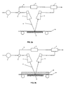
- FIG. 1 is a flow chart showing how one embodiment of the apparatus can be used with the method of the present invention to measure moisture content.
- the apparatus includes a microwave radiation source 1 , shown to the left of the coupler 2.
- the microwave radiation source 1 is a swept source that sequentially transmits microwaves with a frequency which changes preferably linearly with time over a specified frequency bandwidth.
- the source (or sources) may be arranged to transmit more than one centre frequency.
- the swept source 1 receives a signal from the switch 15 before sending a signal to the coupler 2.
- the switch 15 determines which centre frequency is transmitted.
- the signal from the swept source 1, once amplified to an appropriate level, is then divided at the coupler 2, with part of the signal passing through a reference channel to the receiver 7, while the remaining signal passes to the transmit antenna 4 in the measurement channel.
- the signals that go to the two different directions are equal, each part being exactly 50% of the original signal.
- sample being measured can be replaced with a continuous flow of bulk material without departing from the principles of the present invention.
- apparatus will be described only with a single sample to be measured.
- the microwaves are directed at the sample by means such as transmitting antenna 4.
- a planar antenna can be used for the same purpose.
- the source signal 10a is a very high frequency microwave signal which is frequency modulated by linearly sweeping the source oscillator from a frequency just below the centre frequency to a frequency just above it over a predetermined bandwidth.
- the preferred centre frequency for the source signal depends on the nature of the sample 14 and the number of frequencies depends on the number of physical parameters to be measured, such as moisture, salt or protein.
- the source signal 10a passes through the sample 14, hits the polariser 5 and is reflected back. As the source signal 10a has passed through the sample it is both attenuated and slowed. The extent of this attenuation is determined mostly by the loss factor ⁇ " of the material of the sample 14 encountered by the source signal. The degree to which the source signal is slowed is predominantly determined by the dielectric constant ⁇ ' of the material 14.
- the polariser 5 changes the polarisation of the signal to that of the receiver antenna 6.
- the transmit antenna 4 and the receiver antenna 6 are essentially identical except that they will be orthogonally polarised. This means that any reflections off the sample, conveyer belt or conveyer belt superstructure or any surroundings, plus any direct radiation from the transmit antenna 4 to the receiver antenna 6, will not be identified by the receiver 7 since these signals will not have the correct polarisation for entry into the receive antenna 6.
- the receiver 7 will detect, in principle, only those electrical changes in the measurement signal due to the presence of a sample 14 in the system.
- the sample 14 will introduce additional phase shift and attenuation in the measurement channel.
- a frequency mixer is used in both reference and measurement channels to measure the phase difference.
- the reference signal 8a goes to an attenuator and phase shifter 3. The attenuator and phase shifter 3 will be set during calibration so that this channel replicates the electrical characteristics of the measurement channel in the absence of a sample 14 or in the presence of a sample of known characteristics.
- the receiver 7 adds the reference signal 8b and the measuring signal 10b in antiphase at the receiver input.
- the inserted phase shift and the attenuation in the reference channel which produces a null signal at the receiver is recorded.
- the recorded phase shift and the attenuation is sent to the processor where the calculation of physical parameters such as moisture is done.
- the method is the same as above and the switch 15 then switches between different frequencies.
- FIGS. 2a and 2b are schematic drawings of one embodiment of the present invention demonstrating a very simple version of an apparatus.
- the microwave source 1 which can be a swept source generates a timed dependent electrical signal, where a part of the signal is divided at the coupler 2 where part of the signal is used as reference signal 9, while the remaining signal passes to the transmit antenna 4 where part of it is reflected from the polariser 5 and going through the object 14. This is called the measurement signal 11.
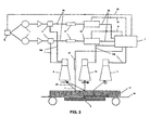
- FIG. 3 is a schematic drawing of a second exemplary embodiment of an apparatus that can be used with the present invention. This apparatus measures similar to the apparatus in Fig. 2 the moisture and sad content of a sample (tobacco), wherein the sample can be in a rest position or being conveyed on a conveyor belt.
- This apparatus uses two frequencies since it is measuring two different physical parameters, moisture and salt content. Therefore the switch 15 switches between 8 GHz and 12 GHz after receiving a signal from the receiver 7. Other frequencies can be used for the same results.
- the apparatus includes a microwave radiation source 1.
- the swept source 1 receives a signal from the switch 15 before sending a signal to the coupler 2.
- the signal from the swept source 1, once amplified to an appropriate level, is then divided at the coupler 2, with part going as a reference signal 8a through a reference channel to the receiver 7, while the remaining signal passes to the transmit antenna 4 as the measurement signal 10a.
- the signals that go to the two different direction are ideally equal, each part being exactly 50% of the original signal.
- the microwaves are directed at the sample and are transmitted from the transmit antenna 4.
- the source 1 is a very high frequency microwave oscillator the frequency of which is changed linearly with time in a repetitive manner over a prescribed bandwidth.
- a part of the transmitted signal 11 passes through the sample 14, hits the polariser and is reflected back. Another part of the transmitted signal 25 is reflected as the signal hits the sample. That part is received by the co-polarised receive antenna 19 and is used to measure the thickness of the sample 14 by detecting the phase shift of the first reflection. The part that passes through the sample 14 and hits the polariser is received, after reflection and change in polarisation, by the transverse polarised receive antenna 6.
- the reference signal 8a goes to a manually adjusted attenuator and phase shifter 17 and then to a programmable/variable attenuator and phase shifter 18.
- the manually adjusted attenuator and phase shifter 17 is used to calibrate the signal once the apparatus is set up so as the summed signal is 0 at a certain frequency in the frequency sweep, when there is no object present.
- Receiver 7 then sends a signal to adjust the programmable/variable attenuator and phase shifter 18 to achieve a summed signal of nullagain. The amount of adjustments is recorded as the measurement values of attenuation and phase of the sample.
- thermometer 20 measures the temperature of the sample 14 and sends a signal to the receiver so that measurements of the relative complex permittivity can be corrected for different temperatures.
- the receiver 7 adds the reference signal 8b and the measuring signal 10b in antiphase.
- phase shift and attenuation 18 is adjusted correctly, a null is detected, meaning that attenuation in 8b is the same as in 10b.
- the phase shift and the attenuation in the reference channel are then recorded.
- the detected phase shift and the attenuation is sent to the processor where the calculation and conversion of values into meaningful information is done.
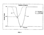
- FIG. 4 is a graph showing an example of an electrical signal from receiver 7 used to calculate the ⁇ ' and ⁇ " of a sample.
- the x-axis represents the frequency sweep of the source and the y-axis shows the strength of the signal.
- response 26 At first, no sample is present and the system is tuned to give response 26.
- response curve 27 Since the signal is unchanged in the reference channel, the sum of the reference signal and the measurement signal changes when sample is present, and this is shown by response curve 27.
- the difference in horizontal direction represents phase change and difference in vertical direction represents attenuation change due to the sample, and these parameters are used to calculate ⁇ ' and ⁇ " according to published formulae.
- Both the wet-mass and the density determination can be based on historic data depending on the object, which can for example be tobacco, wood or corn.
- the object which can for example be tobacco, wood or corn.
- Each of these objects may have their own relation between the phase shift and attenuation and the actual moisture content and density. Rather than using formulae, one could choose to collect data from the apparatus and fit to the actual values of moisture and density.
- the curve 26 shows a measured signal when there is no sample being measured, as in Fig. 2a.
- the measured signal is the same as the reference signal, but with different polarisation.
- the sum of the reference signal and the measured signal is then 0 at a certain frequency in the sweep.
- the reference value is then 0 for no moisture present.
- the measuring curve 27 shows when the signal goes through a sample with moisture. In this case the sample reduces or attenuates the signal by 50%. Since the reference signal is unchanged, the sum of the reference, signal and the measured signal is changed by 50% in the vertical direction, which is the attenuation axis. If the sample was pure water, absorbing all microwaves, measurement signal would be attenuated to nothing, and only reference signal would be received, giving a straight line at the attenuation level of the reference signal.
- the curve 27 represents a phase shift in the microwaves for a frequency sweep, which can be seen by the location of the minima of the signal, which has moved to the left from f 0 to f 1 .
- This phase shift is as mentioned before used to calculate the density of the sample.
- the volume can be estimated by means of using the co-polarised receive antenna 19 to measure the thickness of the sample 14 , which can be registered periodically. If the object is being transported on a conveyer belt with a constant speed, the object can be divided into parts with a fixed height and different thickness.
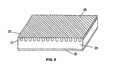
- FIG. 5 shows one embodiment of the polariser, comprised of parallel metallic wires 28 positioned in the horizontal plane of the polarisation plate for rotating at least a part of the transmitted waves. These wires can be supported by a non-reflecting medium 29 such as a plastic material.
- the bottom layer of the polarization plate can be a reflecting material such as a metallic plate 30. As the microwaves hits the polarisation plate part of them hits the wires that rotate the polarisation and a part passes between the wires through the supporting material until it is reflected from the bottom plate 30.
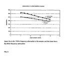
- the following example is based on an experiment that was carried out on 9 samples of tea leaves, where each sample was around 100g, and each with different moisture content, from 5% moisture to 20% moisture. Two swept frequencies were used, one around 8GHz and one around 12GHz. Attenuation was measured in the samples, but not the phase change. The experiment shows that there was a linear relationship between attenuation and actual moisture content of the sample, as can be seen in Fig. 6.
- the correlation coefficient was high, 0.9914 for the 8GHz frequency and 0.9789 for the 12GHz frequency.
- the correlation coefficient is a factor from 0 to 1, which represents how well the data points fall on to fitted line.
Abstract
Description
The apparatus includes a
The
Claims (22)
- An apparatus for measuring at least one physical parameter of an object by means of transmitting microwaves towards the object and analysing the reflected microwaves, said apparatus comprising:a source for generating a time dependent electrical signal,a transmitter positioned in proximity to the object for converting the time dependent electrical signal to microwaves and transmitting the microwaves towards the object,a polarizer positioned adjacent to the object and opposite to the transmitter for rotating at least part of the polarisation of the transmitted waves and reflecting a predetermined polarity of the transmitted waves,a receiver positioned opposite to the object with respect to the polarizer for receiving the reflected microwaves of predetermined polarity that have passed through the object twice and converting them into an electrical signal,wherein said transmitter and said receiver are orthogonally polarized with respect to each other, anda computer system for utilizing the electrical signal for calculating the at least one physical parameter of the object.
- An apparatus according to claim 1, further comprising control electronics for controlling the source.
- An apparatus according to claim 1 or 2, wherein the polarizer is a plate with a plurality of parallel wires positioned in a horizontal plane of the plate for rotating at least a part of the transmitted waves.
- An apparatus according to any of the preceding claims, wherein the thickness of the polarizer is ¼ of the wavelength of the microwave.
- An apparatus according to any of the preceding claims, further comprising a coupler for dividing the electrical signal between the transmitter and the receiver, wherein the part of the electrical signal to the receiver passes trough a reference channel and is used as a reference signal.
- An apparatus according to any of the preceding claims, wherein the object is being conveyed as the object is being measured.
- An apparatus according to any of the preceding claims, wherein at least one physical parameter is the moisture content and/or the density of the object.
- An apparatus according to any of the preceding claims, wherein the receiver is an antenna.
- An apparatus according to any of the preceding claims, wherein the receiver is a diode.
- An apparatus according to any of the preceding claims, further comprising a second receiver positioned opposite to the object with respect to the polarizer for receiving at least part of the reflected microwaves.
- A method for determining at least one physical parameter of an object by means of transmitting a microwave towards the object and measuring the reflection of waves that have passed through the object twice, said method comprising the steps of:generating a time dependent first electrical signal and converting at least part of the first electrical signal to polarized microwaves,transmitting said polarized microwaves towards the object,reflecting the transmitted microwaves by a polarizer positioned adjacent to the object and opposite the transmitter wherein at least part of the polarisation of the reflected microwaves is rotated,receiving the rotated part of the reflected microwaves from the polarizer that have passed through the object twice with a polarized receiver positioned opposite to the object and converting the received part of the transmitted wave into an second electrical signal, the receiver being cross-polarized with respect to the transmitter, andanalysing the second electrical signal and determining at least one physical parameter.
- A method according to claim 11, wherein a part of the first electrical signal is passed through a reference channel to the receiving means and is used as a reference signal.
- A method according to claim 11, wherein at a part of the generated microwaves and a part of the received rotated part of the reflected microwaves from the polarizer are fed to a frequency mixer to determine the phase shift between the generated microwaves and the reflected microwaves caused by the object.
- A method according to any of the claims 11-13, wherein the sum of the second electrical signal and the reference signal is used for determining at least one physical parameter.
- A method according to any of the claims 11-14, wherein the second electrical signal is used for determining at least one physical parameter.
- A method according to any of the claims 11-15. further comprising a second receiving means positioned opposite to the object with respect to the polarizer for receiving at least part of the reflected microwaves of predetermined polarity, wherein the received microwaves are converted into an electrical signal and wherein the phase shift of the electrical signal with respect to a reference signal is used to determine the height of the object.
- A method according to any of the claims 11-16, wherein the attenuation level and the phase shift of the signal is used to calculate the dielectric constant and the loss factor of the object.
- A method according to claim 17, wherein the dielectric constant and the loss factor of the object are used to calculate the density of the object.
- A method according to claim 17, wherein the dielectric constant and the loss factor of the object are used to calculate the moisture content of the object.
- A method according to claim 11, wherein the at feast one physical parameter includes one or more of fat content, salt content, and protein content of said object.
- A method according to any of the claims 16-20, wherein the volume, the density and the moisture content of the object are used to determine weight of the dry mass of the object.
- A method according to any of the claims 11-21, wherein the determination of at least the physical parameter of of an object is based on historical data.
Applications Claiming Priority (5)
| Application Number | Priority Date | Filing Date | Title |
|---|---|---|---|
| US29424901P | 2001-05-31 | 2001-05-31 | |
| IS5960 | 2001-05-31 | ||
| IS596001 | 2001-05-31 | ||
| US294249P | 2001-05-31 | ||
| PCT/IS2002/000011 WO2002097411A1 (en) | 2001-05-31 | 2002-05-31 | Apparatus and method for microwave determination of at least one physical parameter of a substance |
Publications (2)
| Publication Number | Publication Date |
|---|---|
| EP1407254A1 EP1407254A1 (en) | 2004-04-14 |
| EP1407254B1 true EP1407254B1 (en) | 2005-12-28 |
Family
ID=36763231
Family Applications (1)
| Application Number | Title | Priority Date | Filing Date |
|---|---|---|---|
| EP02733210A Expired - Lifetime EP1407254B1 (en) | 2001-05-31 | 2002-05-31 | Apparatus and method for microwave determination of at least one physical parameter of a substance |
Country Status (15)
| Country | Link |
|---|---|
| US (1) | US7187183B2 (en) |
| EP (1) | EP1407254B1 (en) |
| JP (1) | JP2005516181A (en) |
| KR (1) | KR20040020909A (en) |
| CN (1) | CN1287142C (en) |
| AT (1) | ATE314639T1 (en) |
| AU (1) | AU2002304283B2 (en) |
| CA (1) | CA2500191A1 (en) |
| DE (1) | DE60208374T2 (en) |
| DK (1) | DK1407254T3 (en) |
| ES (1) | ES2256478T3 (en) |
| IS (1) | IS7054A (en) |
| NO (1) | NO20035320D0 (en) |
| RU (1) | RU2298197C2 (en) |
| WO (1) | WO2002097411A1 (en) |
Cited By (1)
| Publication number | Priority date | Publication date | Assignee | Title |
|---|---|---|---|---|
| DE102020103978A1 (en) | 2020-02-14 | 2021-08-19 | Tews Elektronik Gmbh & Co. Kg | Device and method for the transmission measurement of reflected microwaves |
Families Citing this family (61)
| Publication number | Priority date | Publication date | Assignee | Title |
|---|---|---|---|---|
| US5914613A (en) | 1996-08-08 | 1999-06-22 | Cascade Microtech, Inc. | Membrane probing system with local contact scrub |
| US6256882B1 (en) | 1998-07-14 | 2001-07-10 | Cascade Microtech, Inc. | Membrane probing system |
| US6914423B2 (en) | 2000-09-05 | 2005-07-05 | Cascade Microtech, Inc. | Probe station |
| US6965226B2 (en) | 2000-09-05 | 2005-11-15 | Cascade Microtech, Inc. | Chuck for holding a device under test |
| DE20114544U1 (en) | 2000-12-04 | 2002-02-21 | Cascade Microtech Inc | wafer probe |
| US7355420B2 (en) | 2001-08-21 | 2008-04-08 | Cascade Microtech, Inc. | Membrane probing system |
| WO2003089948A2 (en) * | 2002-04-15 | 2003-10-30 | Toolz, Ltd. | Constructing a waveform from multiple threshold samples |
| US7492172B2 (en) | 2003-05-23 | 2009-02-17 | Cascade Microtech, Inc. | Chuck for holding a device under test |
| US7057404B2 (en) | 2003-05-23 | 2006-06-06 | Sharp Laboratories Of America, Inc. | Shielded probe for testing a device under test |
| US7250626B2 (en) | 2003-10-22 | 2007-07-31 | Cascade Microtech, Inc. | Probe testing structure |
| WO2005065258A2 (en) | 2003-12-24 | 2005-07-21 | Cascade Microtech, Inc. | Active wafer probe |
| US7187188B2 (en) | 2003-12-24 | 2007-03-06 | Cascade Microtech, Inc. | Chuck with integrated wafer support |
| DE102004031626A1 (en) * | 2004-06-30 | 2006-02-02 | Robert Bosch Gmbh | Method and apparatus for determining the material thickness on a high frequency basis |
| JP2008512680A (en) | 2004-09-13 | 2008-04-24 | カスケード マイクロテック インコーポレイテッド | Double-sided probing structure |
| US7535247B2 (en) | 2005-01-31 | 2009-05-19 | Cascade Microtech, Inc. | Interface for testing semiconductors |
| US7656172B2 (en) | 2005-01-31 | 2010-02-02 | Cascade Microtech, Inc. | System for testing semiconductors |
| US20060220658A1 (en) * | 2005-03-31 | 2006-10-05 | Seichi Okamura | Sensor system for moisture and salt measurement using microstripline |
| JP5008330B2 (en) * | 2006-03-31 | 2012-08-22 | 大和製衡株式会社 | Method and apparatus for measuring lipid content |
| US7764072B2 (en) | 2006-06-12 | 2010-07-27 | Cascade Microtech, Inc. | Differential signal probing system |
| US7403028B2 (en) | 2006-06-12 | 2008-07-22 | Cascade Microtech, Inc. | Test structure and probe for differential signals |
| US7723999B2 (en) | 2006-06-12 | 2010-05-25 | Cascade Microtech, Inc. | Calibration structures for differential signal probing |
| US20080012578A1 (en) * | 2006-07-14 | 2008-01-17 | Cascade Microtech, Inc. | System for detecting molecular structure and events |
| US7876114B2 (en) | 2007-08-08 | 2011-01-25 | Cascade Microtech, Inc. | Differential waveguide probe |
| DE102007057092B4 (en) * | 2007-11-20 | 2009-08-06 | Tews Elektronik Dipl.-Ing. Manfred Tews | Method and device for moisture and / or density measurement |
| DE102008032835A1 (en) * | 2008-07-14 | 2010-01-21 | Hauni Maschinenbau Ag | Method and device for measuring the loading of a strand of the tobacco processing industry with a substance amount |
| JP5421566B2 (en) * | 2008-09-30 | 2014-02-19 | カワサキ機工株式会社 | Method and apparatus for measuring moisture content of tea leaves with low moisture content, and method for controlling tea processing using the same |
| US7888957B2 (en) | 2008-10-06 | 2011-02-15 | Cascade Microtech, Inc. | Probing apparatus with impedance optimized interface |
| WO2010059247A2 (en) | 2008-11-21 | 2010-05-27 | Cascade Microtech, Inc. | Replaceable coupon for a probing apparatus |
| US8319503B2 (en) | 2008-11-24 | 2012-11-27 | Cascade Microtech, Inc. | Test apparatus for measuring a characteristic of a device under test |
| JP5373534B2 (en) * | 2009-10-07 | 2013-12-18 | 三井造船株式会社 | Phase difference measuring method and phase difference measuring apparatus |
| CN105045423B (en) | 2010-02-26 | 2020-09-29 | 辛纳普蒂克斯公司 | Modifying demodulation to avoid interference |
| US9898121B2 (en) | 2010-04-30 | 2018-02-20 | Synaptics Incorporated | Integrated capacitive sensing and displaying |
| DE102011102991B4 (en) * | 2011-05-24 | 2014-02-13 | Krohne Messtechnik Gmbh | Device for determining the volume fraction of at least one component of a multiphase medium |
| CN102621161B (en) * | 2012-03-31 | 2013-10-16 | 中国科学院长春应用化学研究所 | Method for obtaining material performance parameter |
| RU2508534C1 (en) * | 2012-08-13 | 2014-02-27 | Федеральное государственное бюджетное учреждение науки Институт проблем управления им. В.А. Трапезникова Российской академии наук | Device for measurement of dielectric particle geometrical size |
| ITFI20130266A1 (en) * | 2013-11-05 | 2015-05-06 | Advanced Microwave Engineering S R L | ASSOCIATED DEVICE AND ASSOCIATED METHOD FOR THE DETECTION AND MEASUREMENT OF THE PHYSICO-CHEMICAL CHARACTERISTICS OF MATERIALS IN THE FORM OF SHEETS, FILMS, FABRICS, LAYERS DEPOSITED ON A SUPPORT OR SIMILAR. |
| RU2550778C1 (en) * | 2014-01-10 | 2015-05-10 | Учреждение Российской академии наук Институт проблем управления им. В.А. Трапезникова РАН | Method of determining state of road surface |
| RU2552272C1 (en) * | 2014-03-14 | 2015-06-10 | Федеральное государственное бюджетное учреждение науки Институт проблем управления им. В.А. Трапезникова Российской академии наук | Method of determining state of road surface |
| CN106134105B (en) | 2014-03-20 | 2020-02-04 | 艾里尔大学研究与开发有限公司 | Method and system for controlling signal phase and application equipment thereof |
| CN105510386A (en) * | 2014-09-26 | 2016-04-20 | 多瑙控制治理工程有限责任公司 | Radio frequency measurement system for measuring water content of paper and various fiber-containing materials |
| JP6367369B2 (en) * | 2014-12-26 | 2018-08-01 | 日本たばこ産業株式会社 | Filter inspection device |
| US10520302B2 (en) * | 2015-10-02 | 2019-12-31 | Honeywell International Inc. | Monitoring thickness uniformity |
| EP3360247B1 (en) | 2015-10-08 | 2020-12-09 | Ariel-University Research and Development Company Ltd. | Method and system for controlling phase of a signal |
| DE102015225578A1 (en) * | 2015-12-17 | 2017-06-22 | Robert Bosch Gmbh | Apparatus for receiving microwave radiation |
| GB201602773D0 (en) * | 2016-02-17 | 2016-03-30 | Orsus Medical Ltd | A method and apparatus for measuring the concentration of target substances in blood |
| JP6709710B2 (en) * | 2016-09-26 | 2020-06-17 | 株式会社日立製作所 | Inspection equipment |
| US10509378B2 (en) * | 2016-11-07 | 2019-12-17 | FarmX Inc. | Systems and methods for soil modeling and automatic irrigation control |
| US11519896B2 (en) | 2017-01-13 | 2022-12-06 | FarmX Inc. | Soil moisture monitoring systems and methods for measuring mutual inductance of area of influence using radio frequency stimulus |
| US10591423B1 (en) | 2017-03-22 | 2020-03-17 | Northrop Grumman Systems Corporation | Inline fabric conductivity measurement |
| CN107064917A (en) * | 2017-03-30 | 2017-08-18 | 上海斐讯数据通信技术有限公司 | A kind of microwave positioning method and system |
| CN107421967B (en) * | 2017-07-28 | 2020-12-22 | 昆山国显光电有限公司 | Glass detection device and detection method |
| JP2019070535A (en) * | 2017-10-06 | 2019-05-09 | マイクロメジャー株式会社 | Measuring apparatus and measuring method of moisture content rate and the like |
| US11166404B2 (en) | 2018-09-02 | 2021-11-09 | FarmX Inc. | Systems and methods for virtual agronomic sensing |
| RU2690952C1 (en) * | 2018-09-17 | 2019-06-07 | ООО "Генезис-Таврида" | Method of determining percentage of water in a dielectric-water mixture using different dielectrics |
| EP3674703A1 (en) * | 2018-12-31 | 2020-07-01 | INESC TEC - Instituto de Engenharia de Sistemas e Computadores, Tecnologia e Ciência | Method and device for measuring water present in vegetation |
| DE102019101598A1 (en) * | 2019-01-23 | 2020-07-23 | Endress+Hauser SE+Co. KG | Measuring device for determining a dielectric value |
| WO2021033636A1 (en) | 2019-08-20 | 2021-02-25 | 日本たばこ産業株式会社 | Production method and production device for cylindrical heating-type smoking article |
| DE102019008595B4 (en) * | 2019-12-11 | 2021-11-11 | OndoSense GmbH | Method for the determination of parameters of dielectric layers |
| US11533946B2 (en) * | 2020-06-22 | 2022-12-27 | R. J. Reynolds Tobacco Co. | Systems and methods for determining a characteristic of a smoking article |
| US11464179B2 (en) | 2020-07-31 | 2022-10-11 | FarmX Inc. | Systems providing irrigation optimization using sensor networks and soil moisture modeling |
| CN114018955A (en) * | 2021-11-04 | 2022-02-08 | 南京航空航天大学 | Microwave-based device and method for measuring moisture content of storage cigarette packets |
Family Cites Families (25)
| Publication number | Priority date | Publication date | Assignee | Title |
|---|---|---|---|---|
| US3247508A (en) | 1963-10-04 | 1966-04-19 | American Brake Shoe Co | Microwave identification of railroad cars |
| GB1376747A (en) * | 1971-02-11 | 1974-12-11 | Molins Ltd | Monitoring devices |
| US4052666A (en) | 1976-04-15 | 1977-10-04 | Nasa | Remote sensing of vegetation and soil using microwave ellipsometry |
| SE8000410L (en) * | 1979-01-20 | 1980-07-21 | Lambda Ind Science Ltd | flaw detector |
| DE3027094A1 (en) * | 1980-07-17 | 1982-02-04 | Siemens AG, 1000 Berlin und 8000 München | RE-POLARIZING DEVICE FOR GENERATING CIRCULAR POLARIZED ELECTROMAGNETIC WAVES |
| IL66327A0 (en) * | 1982-07-15 | 1982-11-30 | ||
| AT400988B (en) * | 1983-11-07 | 1996-05-28 | Strahlen Umweltforsch Gmbh | METHOD FOR MEASURING WEATHER-CONDITIONS OF STATUS ON THE SURFACE OF TRAFFIC AREAS AND DEVICE FOR IMPLEMENTING THE METHOD |
| US4707652A (en) * | 1983-11-30 | 1987-11-17 | Philip Morris Incorporated | Impurity detector measuring parallel polarized scattered electromagnetic radiation |
| SU1223028A2 (en) * | 1984-07-16 | 1986-04-07 | Казанский Ордена Трудового Красного Знамени И Ордена Дружбы Народов Авиационный Институт Им.А.Н.Туполева | Interferometer for plasma diagnostics |
| US4757514A (en) | 1985-08-13 | 1988-07-12 | Laser Corporation Of America | Wire array light polarizer for gas laser |
| DE3768767D1 (en) * | 1986-11-12 | 1991-04-25 | Atomic Energy Authority Uk | Duennschichtmonitor. |
| US4745361A (en) * | 1987-03-03 | 1988-05-17 | University Of Rochester | Electro-optic measurement (network analysis) system |
| SU1506387A1 (en) | 1987-06-23 | 1989-09-07 | Институт Прикладной Физики Ан Бсср | Device for measuring the thickness of dielectric coatings of metals |
| US4947128A (en) * | 1989-02-23 | 1990-08-07 | Texaco Ijn Inc | Co-variance microwave water cut monitoring means and method |
| US5315258A (en) * | 1989-01-13 | 1994-05-24 | Kajaani Elektroniikka Oy | Method and apparatus for determining the moisture content of a material |
| US5497100A (en) * | 1994-10-17 | 1996-03-05 | Hughes Aircraft Company | Surface condition sensing system |
| AU6888996A (en) * | 1995-09-11 | 1997-04-01 | Yissum Research Development Company Of The Hebrew University Of Jerusalem | Near-field resistivity microscope |
| GB2307611B (en) * | 1995-11-01 | 2000-03-22 | British Gas Plc | Measurement arrangement |
| US6163158A (en) * | 1996-02-20 | 2000-12-19 | Hauni Maschinenbau Ag | Method of and apparatus for ascertaining at least one characteristic of a substance |
| US5959594A (en) * | 1997-03-04 | 1999-09-28 | Trw Inc. | Dual polarization frequency selective medium for diplexing two close bands at an incident angle |
| US6100703A (en) * | 1998-07-08 | 2000-08-08 | Yissum Research Development Company Of The University Of Jerusalum | Polarization-sensitive near-field microwave microscope |
| US6172510B1 (en) * | 1998-12-30 | 2001-01-09 | The United Sates Of America As Represented By The Secretary Of The Navy | System for detection of flaws by use of microwave radiation |
| FI991548A (en) | 1999-07-06 | 2001-04-05 | Neles Field Controls Oy | Method for measuring web consistency and measuring device |
| US6529154B1 (en) * | 2000-03-16 | 2003-03-04 | The United States Of America As Represented By The Administrator Of The National Aeronautics And Space Administration | Method and apparatus for reading two dimensional identification symbols using radar techniques |
| AU2001282722A1 (en) | 2000-08-15 | 2002-02-25 | Industrial Research Limited | Apparatus and method for measuring characteristics of anisotropic materials |
-
2002
- 2002-05-31 EP EP02733210A patent/EP1407254B1/en not_active Expired - Lifetime
- 2002-05-31 RU RU2003137895/09A patent/RU2298197C2/en not_active IP Right Cessation
- 2002-05-31 ES ES02733210T patent/ES2256478T3/en not_active Expired - Lifetime
- 2002-05-31 CN CNB028134362A patent/CN1287142C/en not_active Expired - Fee Related
- 2002-05-31 AU AU2002304283A patent/AU2002304283B2/en not_active Ceased
- 2002-05-31 JP JP2003500541A patent/JP2005516181A/en active Pending
- 2002-05-31 US US10/479,324 patent/US7187183B2/en not_active Expired - Fee Related
- 2002-05-31 DE DE60208374T patent/DE60208374T2/en not_active Expired - Fee Related
- 2002-05-31 AT AT02733210T patent/ATE314639T1/en not_active IP Right Cessation
- 2002-05-31 WO PCT/IS2002/000011 patent/WO2002097411A1/en active IP Right Grant
- 2002-05-31 CA CA002500191A patent/CA2500191A1/en not_active Abandoned
- 2002-05-31 KR KR10-2003-7015628A patent/KR20040020909A/en not_active Application Discontinuation
- 2002-05-31 DK DK02733210T patent/DK1407254T3/en active
-
2003
- 2003-11-27 IS IS7054A patent/IS7054A/en unknown
- 2003-11-28 NO NO20035320A patent/NO20035320D0/en not_active Application Discontinuation
Cited By (2)
| Publication number | Priority date | Publication date | Assignee | Title |
|---|---|---|---|---|
| DE102020103978A1 (en) | 2020-02-14 | 2021-08-19 | Tews Elektronik Gmbh & Co. Kg | Device and method for the transmission measurement of reflected microwaves |
| WO2021160387A1 (en) | 2020-02-14 | 2021-08-19 | Tews Elektronik Gmbh & Co. Kg | Device and method for the transmission measurement of reflected microwaves |
Also Published As
| Publication number | Publication date |
|---|---|
| ATE314639T1 (en) | 2006-01-15 |
| DK1407254T3 (en) | 2006-05-22 |
| CN1559004A (en) | 2004-12-29 |
| KR20040020909A (en) | 2004-03-09 |
| US7187183B2 (en) | 2007-03-06 |
| EP1407254A1 (en) | 2004-04-14 |
| NO20035320D0 (en) | 2003-11-28 |
| CN1287142C (en) | 2006-11-29 |
| JP2005516181A (en) | 2005-06-02 |
| ES2256478T3 (en) | 2006-07-16 |
| DE60208374T2 (en) | 2006-09-07 |
| US20040239338A1 (en) | 2004-12-02 |
| WO2002097411A1 (en) | 2002-12-05 |
| IS7054A (en) | 2003-11-27 |
| RU2298197C2 (en) | 2007-04-27 |
| DE60208374D1 (en) | 2006-02-02 |
| AU2002304283B2 (en) | 2007-10-11 |
| CA2500191A1 (en) | 2002-12-05 |
| RU2003137895A (en) | 2005-06-10 |
Similar Documents
| Publication | Publication Date | Title |
|---|---|---|
| EP1407254B1 (en) | Apparatus and method for microwave determination of at least one physical parameter of a substance | |
| AU2002304283A1 (en) | Apparatus and method for microwave determination of at least one physical parameter of a substance | |
| Ma et al. | Permittivity determination using amplitudes of transmission and reflection coefficients at microwave frequency | |
| US4500835A (en) | Method and apparatus for detecting grain direction in wood, particularly in lumber | |
| CA1247724A (en) | Microwave reflection survey equipment and technique | |
| JP2005516181A5 (en) | ||
| US4514680A (en) | Flaw detection system using microwaves | |
| US5666061A (en) | Apparatus and method for measurement of moisture concentration in granular materials | |
| Okamura | Microwave technology for moisture measurement | |
| US5256978A (en) | Microwave moisture content analyzer | |
| Trabelsi et al. | Microwave moisture sensor for grain and seed | |
| Trabelsi et al. | Microwave moisture meter for granular and particulate materials | |
| EP0487582B1 (en) | Moisture content by microwave phase shift and mass/area | |
| Trabelsi et al. | Universal calibration method for microwave moisture sensing in granular materials | |
| Trabelsi et al. | Practical microwave meter for sensing moisture and density of granular materials | |
| Trabelsi et al. | Microwave sensor for simultaneous and nondestructive determination of moisture content and bulk density of granular materials | |
| RU2790085C1 (en) | Method for remote measurement of complex dielectric permittivacy of plane layered dielectrics of natural origin | |
| EP3066457B1 (en) | Device for the detection and measurement of the physical-chemical features of materials in the form of sheets, films, fabrics, layers deposited on a support or the like | |
| Toropainen | New method for measuring properties of nonhomogeneous materials by a two-polarization forward-scattering measurement | |
| RU2805032C1 (en) | Radar method for monitoring concrete structures | |
| AU635313B2 (en) | Moisture content by microwave phase shift and mass/area | |
| Thakur et al. | Noncontact measurement of moisture in layered dielectrics from microwave reflection spectroscopy using an inverse technique | |
| CN205404449U (en) | Grain moisture detecting system based on super broadband signal | |
| Wenquan et al. | A Simple Terahertz Polarization-Excitation-Based Method for Measuring Refractive Index of Planar Medium | |
| Yordanov et al. | Calibration techniques for microwave moisture meters |
Legal Events
| Date | Code | Title | Description |
|---|---|---|---|
| PUAI | Public reference made under article 153(3) epc to a published international application that has entered the european phase |
Free format text: ORIGINAL CODE: 0009012 |
|
| 17P | Request for examination filed |
Effective date: 20031216 |
|
| AK | Designated contracting states |
Kind code of ref document: A1 Designated state(s): AT BE CH CY DE DK ES FI FR GB GR IE IT LI LU MC NL PT SE TR |
|
| AX | Request for extension of the european patent |
Extension state: AL LT LV MK RO SI |
|
| GRAP | Despatch of communication of intention to grant a patent |
Free format text: ORIGINAL CODE: EPIDOSNIGR1 |
|
| GRAS | Grant fee paid |
Free format text: ORIGINAL CODE: EPIDOSNIGR3 |
|
| GRAA | (expected) grant |
Free format text: ORIGINAL CODE: 0009210 |
|
| AK | Designated contracting states |
Kind code of ref document: B1 Designated state(s): AT BE CH CY DE DK ES FI FR GB GR IE IT LI LU MC NL PT SE TR |
|
| REG | Reference to a national code |
Ref country code: GB Ref legal event code: FG4D |
|
| REG | Reference to a national code |
Ref country code: CH Ref legal event code: EP |
|
| REG | Reference to a national code |
Ref country code: IE Ref legal event code: FG4D |
|
| REF | Corresponds to: |
Ref document number: 60208374 Country of ref document: DE Date of ref document: 20060202 Kind code of ref document: P |
|
| REG | Reference to a national code |
Ref country code: SE Ref legal event code: TRGR |
|
| REG | Reference to a national code |
Ref country code: CH Ref legal event code: NV Representative=s name: ISLER & PEDRAZZINI AG |
|
| REG | Reference to a national code |
Ref country code: DK Ref legal event code: T3 |
|
| REG | Reference to a national code |
Ref country code: GR Ref legal event code: EP Ref document number: 20060401161 Country of ref document: GR |
|
| PG25 | Lapsed in a contracting state [announced via postgrant information from national office to epo] |
Ref country code: MC Free format text: LAPSE BECAUSE OF NON-PAYMENT OF DUE FEES Effective date: 20060531 |
|
| REG | Reference to a national code |
Ref country code: ES Ref legal event code: FG2A Ref document number: 2256478 Country of ref document: ES Kind code of ref document: T3 |
|
| ET | Fr: translation filed | ||
| PLBE | No opposition filed within time limit |
Free format text: ORIGINAL CODE: 0009261 |
|
| STAA | Information on the status of an ep patent application or granted ep patent |
Free format text: STATUS: NO OPPOSITION FILED WITHIN TIME LIMIT |
|
| 26N | No opposition filed |
Effective date: 20060929 |
|
| REG | Reference to a national code |
Ref country code: CH Ref legal event code: PCAR Free format text: ISLER & PEDRAZZINI AG;POSTFACH 1772;8027 ZUERICH (CH) |
|
| PGFP | Annual fee paid to national office [announced via postgrant information from national office to epo] |
Ref country code: CH Payment date: 20080514 Year of fee payment: 7 Ref country code: ES Payment date: 20080527 Year of fee payment: 7 Ref country code: LU Payment date: 20080520 Year of fee payment: 7 |
|
| PGFP | Annual fee paid to national office [announced via postgrant information from national office to epo] |
Ref country code: AT Payment date: 20080522 Year of fee payment: 7 |
|
| PGFP | Annual fee paid to national office [announced via postgrant information from national office to epo] |
Ref country code: IT Payment date: 20080526 Year of fee payment: 7 Ref country code: FI Payment date: 20080522 Year of fee payment: 7 Ref country code: TR Payment date: 20080526 Year of fee payment: 7 Ref country code: PT Payment date: 20080513 Year of fee payment: 7 Ref country code: BE Payment date: 20080522 Year of fee payment: 7 |
|
| PGFP | Annual fee paid to national office [announced via postgrant information from national office to epo] |
Ref country code: IE Payment date: 20080521 Year of fee payment: 7 Ref country code: SE Payment date: 20080520 Year of fee payment: 7 |
|
| PG25 | Lapsed in a contracting state [announced via postgrant information from national office to epo] |
Ref country code: CY Free format text: LAPSE BECAUSE OF FAILURE TO SUBMIT A TRANSLATION OF THE DESCRIPTION OR TO PAY THE FEE WITHIN THE PRESCRIBED TIME-LIMIT Effective date: 20051228 |
|
| PGFP | Annual fee paid to national office [announced via postgrant information from national office to epo] |
Ref country code: GR Payment date: 20080529 Year of fee payment: 7 |
|
| BERE | Be: lapsed |
Owner name: *INTELSCAN ORBYLGJUTAEKNI EHF. Effective date: 20090531 |
|
| REG | Reference to a national code |
Ref country code: PT Ref legal event code: MM4A Free format text: LAPSE DUE TO NON-PAYMENT OF FEES Effective date: 20091130 |
|
| REG | Reference to a national code |
Ref country code: CH Ref legal event code: PL |
|
| PG25 | Lapsed in a contracting state [announced via postgrant information from national office to epo] |
Ref country code: LI Free format text: LAPSE BECAUSE OF NON-PAYMENT OF DUE FEES Effective date: 20090531 Ref country code: CH Free format text: LAPSE BECAUSE OF NON-PAYMENT OF DUE FEES Effective date: 20090531 Ref country code: FI Free format text: LAPSE BECAUSE OF NON-PAYMENT OF DUE FEES Effective date: 20090531 Ref country code: AT Free format text: LAPSE BECAUSE OF NON-PAYMENT OF DUE FEES Effective date: 20090531 |
|
| PGFP | Annual fee paid to national office [announced via postgrant information from national office to epo] |
Ref country code: DE Payment date: 20091130 Year of fee payment: 8 Ref country code: DK Payment date: 20091130 Year of fee payment: 8 |
|
| PGFP | Annual fee paid to national office [announced via postgrant information from national office to epo] |
Ref country code: NL Payment date: 20091130 Year of fee payment: 8 |
|
| REG | Reference to a national code |
Ref country code: IE Ref legal event code: MM4A |
|
| PG25 | Lapsed in a contracting state [announced via postgrant information from national office to epo] |
Ref country code: PT Free format text: LAPSE BECAUSE OF NON-PAYMENT OF DUE FEES Effective date: 20091130 |
|
| PG25 | Lapsed in a contracting state [announced via postgrant information from national office to epo] |
Ref country code: IE Free format text: LAPSE BECAUSE OF NON-PAYMENT OF DUE FEES Effective date: 20090531 |
|
| PGFP | Annual fee paid to national office [announced via postgrant information from national office to epo] |
Ref country code: FR Payment date: 20091211 Year of fee payment: 8 Ref country code: GB Payment date: 20091130 Year of fee payment: 8 |
|
| PG25 | Lapsed in a contracting state [announced via postgrant information from national office to epo] |
Ref country code: GR Free format text: LAPSE BECAUSE OF NON-PAYMENT OF DUE FEES Effective date: 20091202 Ref country code: BE Free format text: LAPSE BECAUSE OF NON-PAYMENT OF DUE FEES Effective date: 20090531 |
|
| REG | Reference to a national code |
Ref country code: ES Ref legal event code: FD2A Effective date: 20090601 |
|
| PG25 | Lapsed in a contracting state [announced via postgrant information from national office to epo] |
Ref country code: ES Free format text: LAPSE BECAUSE OF NON-PAYMENT OF DUE FEES Effective date: 20090601 |
|
| REG | Reference to a national code |
Ref country code: NL Ref legal event code: V1 Effective date: 20101201 |
|
| REG | Reference to a national code |
Ref country code: DK Ref legal event code: EBP |
|
| GBPC | Gb: european patent ceased through non-payment of renewal fee |
Effective date: 20100531 |
|
| REG | Reference to a national code |
Ref country code: FR Ref legal event code: ST Effective date: 20110131 |
|
| PG25 | Lapsed in a contracting state [announced via postgrant information from national office to epo] |
Ref country code: NL Free format text: LAPSE BECAUSE OF NON-PAYMENT OF DUE FEES Effective date: 20101201 Ref country code: IT Free format text: LAPSE BECAUSE OF NON-PAYMENT OF DUE FEES Effective date: 20090531 |
|
| PG25 | Lapsed in a contracting state [announced via postgrant information from national office to epo] |
Ref country code: DE Free format text: LAPSE BECAUSE OF NON-PAYMENT OF DUE FEES Effective date: 20101201 Ref country code: DK Free format text: LAPSE BECAUSE OF NON-PAYMENT OF DUE FEES Effective date: 20100531 Ref country code: LU Free format text: LAPSE BECAUSE OF NON-PAYMENT OF DUE FEES Effective date: 20090531 |
|
| PG25 | Lapsed in a contracting state [announced via postgrant information from national office to epo] |
Ref country code: FR Free format text: LAPSE BECAUSE OF NON-PAYMENT OF DUE FEES Effective date: 20100531 Ref country code: SE Free format text: LAPSE BECAUSE OF NON-PAYMENT OF DUE FEES Effective date: 20090601 |
|
| PG25 | Lapsed in a contracting state [announced via postgrant information from national office to epo] |
Ref country code: GB Free format text: LAPSE BECAUSE OF NON-PAYMENT OF DUE FEES Effective date: 20100531 |
|
| PG25 | Lapsed in a contracting state [announced via postgrant information from national office to epo] |
Ref country code: TR Free format text: LAPSE BECAUSE OF NON-PAYMENT OF DUE FEES Effective date: 20090531 |