EP1410819A1 - Warranty seal for a syringe - Google Patents
Warranty seal for a syringe Download PDFInfo
- Publication number
- EP1410819A1 EP1410819A1 EP03021967A EP03021967A EP1410819A1 EP 1410819 A1 EP1410819 A1 EP 1410819A1 EP 03021967 A EP03021967 A EP 03021967A EP 03021967 A EP03021967 A EP 03021967A EP 1410819 A1 EP1410819 A1 EP 1410819A1
- Authority
- EP
- European Patent Office
- Prior art keywords
- connection
- tamper
- cap
- syringe
- evident closure
- Prior art date
- Legal status (The legal status is an assumption and is not a legal conclusion. Google has not performed a legal analysis and makes no representation as to the accuracy of the status listed.)
- Granted
Links
- 238000003466 welding Methods 0.000 claims description 17
- 239000004033 plastic Substances 0.000 claims description 15
- 229920003023 plastic Polymers 0.000 claims description 15
- 229920000089 Cyclic olefin copolymer Polymers 0.000 claims description 4
- 239000004743 Polypropylene Substances 0.000 claims description 4
- 239000000463 material Substances 0.000 claims description 4
- 229920001155 polypropylene Polymers 0.000 claims description 4
- 229920000098 polyolefin Polymers 0.000 claims description 2
- -1 polypropylene Polymers 0.000 claims description 2
- 238000002347 injection Methods 0.000 description 11
- 239000007924 injection Substances 0.000 description 11
- 238000004519 manufacturing process Methods 0.000 description 4
- 238000000034 method Methods 0.000 description 4
- 229940071643 prefilled syringe Drugs 0.000 description 3
- 238000007789 sealing Methods 0.000 description 3
- 238000004026 adhesive bonding Methods 0.000 description 2
- POIUWJQBRNEFGX-XAMSXPGMSA-N cathelicidin Chemical compound C([C@@H](C(=O)N[C@@H](CCCNC(N)=N)C(=O)N[C@@H](CCCCN)C(=O)N[C@@H](CO)C(=O)N[C@@H](CCCCN)C(=O)N[C@@H](CCC(O)=O)C(=O)N[C@@H](CCCCN)C(=O)N[C@@H]([C@@H](C)CC)C(=O)NCC(=O)N[C@@H](CCCCN)C(=O)N[C@@H](CCC(O)=O)C(=O)N[C@@H](CC=1C=CC=CC=1)C(=O)N[C@@H](CCCCN)C(=O)N[C@@H](CCCNC(N)=N)C(=O)N[C@@H]([C@@H](C)CC)C(=O)N[C@@H](C(C)C)C(=O)N[C@@H](CCC(N)=O)C(=O)N[C@@H](CCCNC(N)=N)C(=O)N[C@@H]([C@@H](C)CC)C(=O)N[C@@H](CCCCN)C(=O)N[C@@H](CC(O)=O)C(=O)N[C@@H](CC=1C=CC=CC=1)C(=O)N[C@@H](CC(C)C)C(=O)N[C@@H](CCCNC(N)=N)C(=O)N[C@@H](CC(N)=O)C(=O)N[C@@H](CC(C)C)C(=O)N[C@@H](C(C)C)C(=O)N1[C@@H](CCC1)C(=O)N[C@@H](CCCNC(N)=N)C(=O)N[C@@H]([C@@H](C)O)C(=O)N[C@@H](CCC(O)=O)C(=O)N[C@@H](CO)C(O)=O)NC(=O)[C@H](CC=1C=CC=CC=1)NC(=O)[C@H](CC(O)=O)NC(=O)CNC(=O)[C@H](CC(C)C)NC(=O)[C@@H](N)CC(C)C)C1=CC=CC=C1 POIUWJQBRNEFGX-XAMSXPGMSA-N 0.000 description 2
- 239000013013 elastic material Substances 0.000 description 2
- 244000052616 bacterial pathogen Species 0.000 description 1
- 230000004888 barrier function Effects 0.000 description 1
- 150000001875 compounds Chemical class 0.000 description 1
- 238000010276 construction Methods 0.000 description 1
- 230000000694 effects Effects 0.000 description 1
- 238000005516 engineering process Methods 0.000 description 1
- 239000004744 fabric Substances 0.000 description 1
- 239000011521 glass Substances 0.000 description 1
- 230000006698 induction Effects 0.000 description 1
- 230000036512 infertility Effects 0.000 description 1
- 238000002844 melting Methods 0.000 description 1
- 230000008018 melting Effects 0.000 description 1
- 235000011837 pasties Nutrition 0.000 description 1
- 230000002093 peripheral effect Effects 0.000 description 1
- 238000004513 sizing Methods 0.000 description 1
- 239000007787 solid Substances 0.000 description 1
Images


Classifications
-
- A—HUMAN NECESSITIES
- A61—MEDICAL OR VETERINARY SCIENCE; HYGIENE
- A61M—DEVICES FOR INTRODUCING MEDIA INTO, OR ONTO, THE BODY; DEVICES FOR TRANSDUCING BODY MEDIA OR FOR TAKING MEDIA FROM THE BODY; DEVICES FOR PRODUCING OR ENDING SLEEP OR STUPOR
- A61M5/00—Devices for bringing media into the body in a subcutaneous, intra-vascular or intramuscular way; Accessories therefor, e.g. filling or cleaning devices, arm-rests
- A61M5/50—Devices for bringing media into the body in a subcutaneous, intra-vascular or intramuscular way; Accessories therefor, e.g. filling or cleaning devices, arm-rests having means for preventing re-use, or for indicating if defective, used, tampered with or unsterile
- A61M5/5086—Devices for bringing media into the body in a subcutaneous, intra-vascular or intramuscular way; Accessories therefor, e.g. filling or cleaning devices, arm-rests having means for preventing re-use, or for indicating if defective, used, tampered with or unsterile for indicating if defective, used, tampered with or unsterile
-
- A—HUMAN NECESSITIES
- A61—MEDICAL OR VETERINARY SCIENCE; HYGIENE
- A61M—DEVICES FOR INTRODUCING MEDIA INTO, OR ONTO, THE BODY; DEVICES FOR TRANSDUCING BODY MEDIA OR FOR TAKING MEDIA FROM THE BODY; DEVICES FOR PRODUCING OR ENDING SLEEP OR STUPOR
- A61M5/00—Devices for bringing media into the body in a subcutaneous, intra-vascular or intramuscular way; Accessories therefor, e.g. filling or cleaning devices, arm-rests
- A61M5/178—Syringes
- A61M5/31—Details
- A61M2005/3103—Leak prevention means for distal end of syringes, i.e. syringe end for mounting a needle
- A61M2005/3104—Caps for syringes without needle
-
- A—HUMAN NECESSITIES
- A61—MEDICAL OR VETERINARY SCIENCE; HYGIENE
- A61M—DEVICES FOR INTRODUCING MEDIA INTO, OR ONTO, THE BODY; DEVICES FOR TRANSDUCING BODY MEDIA OR FOR TAKING MEDIA FROM THE BODY; DEVICES FOR PRODUCING OR ENDING SLEEP OR STUPOR
- A61M5/00—Devices for bringing media into the body in a subcutaneous, intra-vascular or intramuscular way; Accessories therefor, e.g. filling or cleaning devices, arm-rests
- A61M5/178—Syringes
- A61M5/31—Details
- A61M2005/3117—Means preventing contamination of the medicament compartment of a syringe
- A61M2005/3118—Means preventing contamination of the medicament compartment of a syringe via the distal end of a syringe, i.e. syringe end for mounting a needle cannula
- A61M2005/312—Means preventing contamination of the medicament compartment of a syringe via the distal end of a syringe, i.e. syringe end for mounting a needle cannula comprising sealing means, e.g. severable caps, to be removed prior to injection by, e.g. tearing or twisting
Definitions
- the invention relates to a tamper evident closure for a syringe according to the features specified in the preamble of claim 1.
- syringes In syringes, especially prefilled syringes, is a tamper-evident closure provided that the originality for the user, d. H. the integrity the closure and thus the filled in the syringe Guaranteed by means.
- tamper evident closures count to State of the art and are known for example from EP 0397951 A1.
- the syringe described there is one such Glass cylinder, attached to the end of a plastic component is, which has a Luer connector on the later Cannula is plugged in a conventional manner or on the Syringe is connected in any other way.
- This Luer connector is with a plug sealed, which the free end both inside as well as completely encompasses outside.
- This stopper is held by a plastic cap, which over a divider with a ring as Fixing component is connected.
- This ring has a projection in a corresponding recess at the connection end of the The syringe engages and holds it there.
- cap, divider and ring typically integrally formed as an injection molded part and are pushed over the connection end of the syringe until the Latch on the ring at the connection end engages.
- the invention is based on the object Tamper evident closure of the type mentioned above to improve that he is on the one hand inexpensive to produce, but on the other hand reliably guarantees the integrity of the closure, as long as his divider is intact.
- the basic idea of the present invention is the tamper-evident closure no longer by locking connection, but rather a cohesive Connection to the connection end of the syringe to connect.
- the cohesive connection can be made by gluing or preferably done by welding. It can either the divider welded directly on the connection end of the syringe be or, which is less expensive to produce, the divider be connected in a conventional manner with a fixing, the then connected by welding to the connection end of the syringe is.
- cohesive Compound that is made only after sliding the cap, a much more durable connection can be created than this is possible in the previously known snap-in connections. Thereby The components can be manufactured with greater tolerance, which respect the manufacturing costs of advantage.
- the divider can the Requirements are sized accordingly, so that the opening forces are specifically adjustable. Also the tool costs can be reduced thereby. If the divider directly to the connection side The end of the syringe is welded, it plays for the functionality the shutter does not matter, whether when opening, d. H. when tearing off the cap, the divider or the weld broken becomes. Therefore, embodiments are also conceivable in which the separating web is formed by the weld itself, d. H. at the Weld forms the predetermined breaking point.
- cap, divider and Fixierbauteil integrally formed as an injection molded part, in which case the fixing after placing the cap by welding with the connecting end of the syringe is firmly connected.
- the fixing component and the connection-side end the syringe can perform the welding process in a simple manner because there are no special requirements regarding tolerances consist.
- a circumferential weld can usually a so stable bond between fixing and connection end the syringe are made that even with unfavorable sizing of the divider is always ensured that the breaking point by the divider and not by other components or the weld is formed.
- Such a ring can, for example, in a syringe with Luer lock readily at the syringe-side cylinder portion welded on the inside of the thread of the Luer lock connector wearing.
- Under cylinder section in the context of the invention always a hollow cylinder, so to understand an annular body.
- the annular fixing component is free Tapered tapering end of the cylinder portion formed is, so it is for example a cone-shaped ring because then the component remaining after tearing off the cap is suitable, Immediately pushing a hose onto the Luer lock connection to facilitate and the hose against the outer circumference the Luer lock connection to seal through this raised ring.
- the ring then forms not only Fixierbauteil, but improved at the same time the possible uses of the syringe.
- the fixing component is formed by the cylinder portion of the Luerlockan gleiches itself. Then, namely, the connection-side end of the syringe without undercuts be formed, d. H. with a comparatively little effort Tool to be made. This is especially true of Advantage, if the syringe-side connection together with the syringe barrel is prepared, as is known in plastic syringes.
- the Welded joint between cylinder section and the connection side The end of the syringe barrel then not only connects the fixing component with the syringe barrel, but also serves as a constructive Connection between cylinder section of the Luer lock connection and the syringe barrel, so in any case meets structurally anyway Necessary measures.
- the divider is then at a suitable location, for example, the front side of the cylinder portion or near this end face formed.
- the fixing for example, to design as a tapered ring to on this way pushing a hose and the seal between hose and cylinder section to allow. It can either this annular fixing member on the cylinder portion of the Luer lock connector be welded or if the cylinder section the Luerlock connection itself forms the fixing, at this be additionally formed.
- the divider is circumferentially formed, since he then at the same time also a hermetic conclusion between Fixierbauteil and cap forms. He can, however, also trained interrupted be, so that forms a plurality of individual webs in the manner of a Perforation. Preferably, however, it is evenly distributed over the circumference designed so that the cap from all directions equally easy or difficult to remove. There may also be several dividers be provided. For example, a cancel on a targeted Predetermined breaking point, the divider can only one-sided be provided.
- the end of the syringe is preferably by ultrasonic welding However, it can also be produced by vibration welding, induction welding, Gluing or other suitable methods for achieving a Formed material bond. It is particularly advantageous if the connecting end of the syringe together with the syringe barrel as Plastic injection molded part is integrally formed, since then for the entire Syringe only a few components and correspondingly few assembly steps required are.
- the over the fixing ring or directly attached cap can, as known per se, have integrated an elastic plug, the sealing seals the connection end of the syringe.
- This plug can either be integrated as a separate component in the cap or be extruded together with the cap as a one-piece component.
- the invention may also be provided, the comparatively Hard elastic cap material directly for sealing the Luer connection to use by welding the Cap this shortened by melting the material targeted and to put it under pretension, leaving the inside of the cap bears with this biasing force on the front side of the Luer connector. It is then an elastic material to the end dispensable.
- the syringe, in particular the injection-cylinder-side part will be advantageous made of polyolefins, preferably polypropylene (PP), cycloolefin polymers (COP) or other barrier plastics
- polyolefins preferably polypropylene (PP), cycloolefin polymers (COP) or other barrier plastics
- connection-side end of a syringe barrel 1 is shown, which opens into a Luer connection 2, in a conventional manner is provided for placing a cannula.
- the Luer connector 2 and the Syringe cylinders 1 are integrally formed as a plastic injection molded part.
- Luer connector 2 As a tamper-evident closure is the Luer connector 2 at the free end provided by far covering cap 3, which via a circumferential divider 4 is connected to a cylinder section 5, which has on its inside a thread 6 and the Luer connection 2 surrounding the connection end of the syringe barrel 1 connects.
- Cap 3, divider 4 and cylinder section 5 are also integrally formed as a plastic injection molded part.
- the cylinder section 5 is at its pointing to the syringe barrel 1 end face with this by ultrasonic welding cohesively and firmly connected.
- the weld is marked with 7.
- the thus-formed tamper-evident closure is for a non-prefilled or provided with pasty fabric pre-filled syringe.
- the cap 3 by hand force from the cylinder section. 5 removed, wherein the divider 4, which is a predetermined breaking point, destroyed becomes.
- the arrangement and configuration of the cylinder portion 5 in relation on the Luer connector 2 are chosen so that after removing the cap 3 a Luer lock connection is formed.
- a complete Luerlockan gleich consisting of the inner Luer connector 2 and a Cylinder section 5 formed with internal thread 6.
- a cap 8 is provided, which over a section wise broken divider 9 with a fixing member 10 in Form of a ring is connected.
- the ring 10 engages over the end portion the cylinder portion 5 of the Luerlockan gleiches on the outer circumference.
- the Components are fixed in the overlapping area by ultrasonic welding connected with each other.
- the weld is marked 11.
- a plug 12 is incorporated, which is the Luer connection both inside and outside the end encompasses and tight closes.
- the plug 12 is formed of a soft-elastic material, whereas the cap 8, the divider 9 and the ring 10 are made a harder plastic as well as the syringe barrel 1 with the formed thereon Luer lock connection are made.
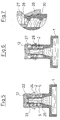
- the embodiment according to FIG. 2 is in particular for a prefilled syringe suitable.
- a prefilled syringe suitable To open the cap 8 from the connection side syringe end deducted, whereby the divider 9 and the plurality on the Circumference distributed arranged dividers demolish and along with the plug 12 can be removed.
- Fig. 3 is the connection-side end of the syringe barrel 1 in the same manner as that of FIG. 2 is formed.
- the cap has a cylindrical section 14 with external thread, in the internal thread 6 of the cylinder portion 5 of the Luerlockan gleiches engages and thus holds the cap form-fitting.
- the Cap 13 also has on its inside a plug 15, which is provided for tight completion of the Luer connector 2.
- a circumferential divider 16 formed, extending from the frontal outer edge of the cap 13 to the front End of the cylinder portion 5 extends, where it by ultrasonic welding connected to this materially.
- the cap 13 and the divider 16 in one piece as a plastic injection molded part educated. To open the tamper-evident closure the cap 13 is unscrewed from the Luerlockgewinde, wherein the divider 16 breaks off.
- FIG. 4 shows a tamper-evident closure for a not pre-filled syringe with a syringe barrel 1 with Luer connector 2.
- a cup-shaped cap 18 is connected via a peripheral separating web 19 with a fixing member 20 in the form of a cylindrical portion in one piece and designed as a plastic injection molded part.
- the fixing member 20 is similar Way as in the embodiment of FIG. 1 frontally with the syringe barrel 1 connected by welding.
- the weld is marked 21.
- the cap 18 is by hand force from the fixing member 20th separated, wherein the divider 19 is destroyed and the end of the Luer connection 2 becomes accessible.
- connection-side end of a syringe barrel illustrated with reference to FIG. 5 1 opens into a Luer connector 2 and is integral with this educated.
- a cap 22, similar to that described with reference to FIG. 2, is via a broken divider 23 with a cylinder section 5 connected with internal thread 6, the part of after losing weight the cap 22 resulting Luer lock connection is.
- the cylinder portion 5 is near its free end in cross section tapered ring 24 integrally formed, which together with the Cylinder section 5, the separating web 23 and the cap 22 as an injection molded part is trained.
- the cap 22nd a plug 12, which for the tight completion of the Luer connection. 2 serves.
- the embodiment variant illustrated with reference to FIGS. 6 and 7 differs differ from the above by the fact that in this case the connection-side end of the syringe barrel 1 in one piece with a Luer lock connection is formed.
- the cap 27 is over a divider 28, which extends over the entire frontal circumference, however is interrupted in sections, connected to a fixing member 29 and integrally formed as an injection molded part, which, as is apparent from Fig. 7 results, has substantially the shape of the conical ring 24.
- the fixing member is by welding on the outer circumference the cylinder portion 5 is fixed, the weld is 30 characterized.
- the fixing member 29 has, after the cap 27 through Tearing the divider 28 has been removed, the same function like the conical ring 24 described with reference to FIG.
- the present invention in addition to a functionally reliable tamper-evident closure also include other features, especially in Combination production technology are low to produce. It understands itself that the above-described individual features to be understood only as an example are and therefore, as far as practical, practically arbitrary with each other can be combined. For example, even those without plugs illustrated embodiments with such produced or vice versa. Allen has in common is that due to the cohesive solid welded connection reliably ensures that when separating a cap always the divider and not the fixing (as in the prior art) is solved. That way is after removing the cap the tamper evident closure is reliably destroyed.
Abstract
Description
Die Erfindung betrifft einen Originalitätsverschluss für eine Spritze gemäß den im Oberbegriff des Anspruchs 1 angegebenen Merkmalen.The invention relates to a tamper evident closure for a syringe according to the features specified in the preamble of claim 1.
Bei Spritzen, insbesondere vorgefüllten Spritzen, ist ein Originalitätsverschluss vorgesehen, der für den Anwender die Originalität, d. h. die Unversehrtheit des Verschlusses und damit des in der Spritze abgefüllten Mittels gewährleistet. Derartige Originalitätsverschlüsse zählen zum Stand der Technik und sind beispielsweise aus EP 0 397 951 A1 bekannt. Bei der dort beschriebenen Spritze handelt es sich um eine solche mit Glaszylinder, an deren Ende ein aus Kunststoff bestehendes Bauteil angebracht ist, welches einen Lueranschluss aufweist, auf den später die Kanüle in an sich bekannter Weise aufgesteckt wird oder über den die Spritze in sonstiger Weise angeschlossen wird. Dieser Lueranschluss ist mit einem Stopfen dicht verschlossen, welcher das freie Ende sowohl innen als auch außen vollständig umgreift. Gehalten wird dieser Stopfen von einer Kunststoffkappe, welche über einen Trennsteg mit einem Ring als Fixierbauteil verbunden ist. Dieser Ring weist einen Vorsprung auf, der in einer entsprechenden Ausnehmung am anschlussseitigen Ende der Spritze eingreift und diesen dort festhält. Dabei sind Kappe, Trennsteg und Ring typischerweise einstückig als Spritzgussteil ausgebildet und werden über das anschlussseitige Ende der Spritze geschoben, bis der Vorsprung am Ring am anschlussseitigen Ende einrastet.In syringes, especially prefilled syringes, is a tamper-evident closure provided that the originality for the user, d. H. the integrity the closure and thus the filled in the syringe Guaranteed by means. Such tamper evident closures count to State of the art and are known for example from EP 0397951 A1. The syringe described there is one such Glass cylinder, attached to the end of a plastic component is, which has a Luer connector on the later Cannula is plugged in a conventional manner or on the Syringe is connected in any other way. This Luer connector is with a plug sealed, which the free end both inside as well as completely encompasses outside. This stopper is held by a plastic cap, which over a divider with a ring as Fixing component is connected. This ring has a projection in a corresponding recess at the connection end of the The syringe engages and holds it there. Here are cap, divider and ring typically integrally formed as an injection molded part and are pushed over the connection end of the syringe until the Latch on the ring at the connection end engages.
Problematisch bei solchen Originalitätsverschlüssen, welche rastend auf das anschlussseitige Ende der Spritze aufgeschoben werden, ist, dass die Fertigungstoleranzen vergleichsweise eng sind um sicherzustellen, dass beim Abnehmen der Kappe tatsächlich der Trennsteg bricht und nicht die Verbindung zwischen dem fixierenden Ring und dem anschlussseitigen Ende der Spritze. Dann nämlich kann der Verschluss ohne weiteres wieder aufgesetzt werden, ohne dass die Originalität und damit die Sterilität des Produktes gewährleistet ist. Darüber hinaus besteht die Gefahr, dass der Trennsteg durch Einknicken bzw. Überdehnen schon beim Aufsetzen bricht. Darüber hinaus ist der Trennsteg häufig so massiv ausgebildet, dass ein Abnehmen der Kappe durch Aufbringen von Zugkräften allein nicht ausreicht, dass vielmehr die Kappe gegenüber dem fixierenden Ring durch Handkraft zusätzlich verdreht werden muss. Dann jedoch sind beide Hände erforderlich, eine zum Fassen des fixierenden Rings und die andere zum Fassen der Kappe. Abgesehen davon, dass dies umständlich ist, besteht insbesondere bei den hier in Rede stehenden medizinischen Spritzen stets die Gefahr, dass hierdurch Keime in diesen Bereich gelangen. Eine dünnere Dimensionierung des Trennstegs ist häufig gar nicht möglich oder werkzeugtechnisch nur schwierig zu realisieren, da nämlich der fixierende Ring in der Regel über den Trennsteg beim Spritzvorgang mit Kunststoff gefüllt werden muss, so dass schon aus diesem Grund ein gewisser Mindestquerschnitt vorhanden sein muss, um ein vollständiges Füllen des fixierenden Rings beim Spritzvorgang sicherzustellen.The problem with such tamper-evident closures, which latching on the connection end of the syringe to be pushed, is that the manufacturing tolerances are comparatively tight to ensure that when removing the cap actually breaks the divider and not the connection between the fixing ring and the connection side End of the syringe. Then the shutter can be without be put back together without the originality and so that the sterility of the product is guaranteed. In addition there is the risk that the divider by buckling or overstretching already breaks at touchdown. In addition, the divider is often like this massively formed, that a removal of the cap by applying Of tensile forces alone is not enough, that rather the cap opposite The fixing ring can be twisted by hand got to. But then both hands are needed, one for grasping the fixing ring and the other for grasping the cap. apart The fact that this is cumbersome, especially in the here in Talking about medical syringes always the danger of doing so Germs get into this area. A thinner dimensioning of the Trennstegs is often not possible or tool technical only difficult to realize, because the fixing ring is usually over the divider to be filled with plastic during the injection process must, so that already for this reason a certain minimum cross-section must be present to complete filling of the fixing ring to ensure during the injection process.
Vor diesem Hintergrund liegt der Erfindung die Aufgabe zugrunde, einen Originalitätsverschluss der eingangs genannten Art dahingehend zu verbessern, dass er einerseits kostengünstig herstellbar ist, jedoch andererseits zuverlässig die Unversehrtheit des Verschlusses garantiert, solange sein Trennsteg unversehrt ist.Against this background, the invention is based on the object Tamper evident closure of the type mentioned above to improve that he is on the one hand inexpensive to produce, but on the other hand reliably guarantees the integrity of the closure, as long as his divider is intact.
Diese Aufgabe wird gemäß der Erfindung durch die in Anspruch 1 angegebenen Merkmale gelöst. Vorteilhafte Ausgestaltungen der Erfindung sind in den Unteransprüchen, der nachfolgenden Beschreibung und der Zeichnung angegeben.This object is achieved according to the invention by those specified in claim 1 Characteristics solved. Advantageous embodiments of the invention are in the subclaims, the following description and the drawing indicated.
Grundgedanke der vorliegenden Erfindung ist es, den Originalitätsverschluss nicht mehr durch Rastverbindung, sondern vielmehr eine stoffschlüssige Verbindung mit dem anschlussseitigen Ende der Spritze zu verbinden. Die stoffschlüssige Verbindung kann durch Kleben oder vorzugsweise durch Schweißen erfolgen. Dabei kann entweder der Trennsteg unmittelbar am anschlussseitigen Ende der Spritze angeschweißt sein oder, was fertigungstechnisch weniger aufwändig ist, der Trennsteg in an sich bekannter Weise mit einem Fixierbauteil verbunden sein, das dann durch Schweißen mit dem anschlussseitigen Ende der Spritze verbunden ist. Durch die gemäß der Erfindung vorgesehene stoffschlüssige Verbindung, die erst nach Aufschieben der Kappe hergestellt wird, kann eine wesentlich haltbarere Verbindung geschaffen werden, als dies bei den bisher bekannten Rastverbindungen möglich ist. Dadurch können die Bauteile mit größerer Toleranz hergestellt werden, was hinsichtlich der Fertigungskosten von Vorteil ist. Der Trennsteg kann den Anforderungen entsprechend dimensioniert werden, so dass die Öffnungskräfte gezielt einstellbar sind. Auch die Werkzeugkosten können hierdurch reduziert werden. Wenn der Trennsteg direkt mit dem anschlussseitigen Ende der Spritze verschweißt wird, spielt es für die Funktionalität des Verschlusses keine Rolle, ob beim Öffnen, d. h. beim Abreißen der Kappe, der Trennsteg oder die Schweißnaht aufgebrochen wird. Es sind daher auch Ausführungen denkbar, bei denen der Trennsteg durch die Schweißnaht selbst gebildet wird, d. h. bei der die Schweißnaht die Sollbruchstelle bildet.The basic idea of the present invention is the tamper-evident closure no longer by locking connection, but rather a cohesive Connection to the connection end of the syringe to connect. The cohesive connection can be made by gluing or preferably done by welding. It can either the divider welded directly on the connection end of the syringe be or, which is less expensive to produce, the divider be connected in a conventional manner with a fixing, the then connected by welding to the connection end of the syringe is. By provided in accordance with the invention cohesive Compound that is made only after sliding the cap, a much more durable connection can be created than this is possible in the previously known snap-in connections. Thereby The components can be manufactured with greater tolerance, which respect the manufacturing costs of advantage. The divider can the Requirements are sized accordingly, so that the opening forces are specifically adjustable. Also the tool costs can be reduced thereby. If the divider directly to the connection side The end of the syringe is welded, it plays for the functionality the shutter does not matter, whether when opening, d. H. when tearing off the cap, the divider or the weld broken becomes. Therefore, embodiments are also conceivable in which the separating web is formed by the weld itself, d. H. at the Weld forms the predetermined breaking point.
Nach einer bevorzugten Ausführungsvariante sind Kappe, Trennsteg und Fixierbauteil einstückig als Spritzgussteil ausgebildet, wobei dann das Fixierbauteil nach Aufsetzen der Kappe durch Schweißen mit dem anschlussseitigen Ende der Spritze fest verbunden wird. Bei entsprechender Auslegung des Fixierbauteils und des anschlussseitigen Endes der Spritze kann der Schweißvorgang in einfacher Weise ausgeführt werden, da keine besonderen Anforderungen hinsichtlich Toleranzen bestehen. Durch eine umlaufende Schweißnaht kann in der Regel ein so stabiler Verbund zwischen Fixierbauteil und anschlussseitigem Ende der Spritze hergestellt werden, dass auch bei ungünstiger Dimensionierung des Trennstegs stets sichergestellt ist, dass die Sollbruchstelle durch den Trennsteg und nicht durch andere Bauteile oder die Schweißnaht gebildet ist.According to a preferred embodiment are cap, divider and Fixierbauteil integrally formed as an injection molded part, in which case the fixing after placing the cap by welding with the connecting end of the syringe is firmly connected. With appropriate Design of the fixing component and the connection-side end the syringe can perform the welding process in a simple manner because there are no special requirements regarding tolerances consist. By a circumferential weld can usually a so stable bond between fixing and connection end the syringe are made that even with unfavorable sizing of the divider is always ensured that the breaking point by the divider and not by other components or the weld is formed.
Ein solcher Ring kann beispielsweise bei einer Spritze mit Luerlockanschluss ohne weiteres an dem spritzenseitigen Zylinderabschnitt angeschweißt werden, der auf seiner Innenseite das Gewinde des Luerlockanschlusses trägt. Unter Zylinderabschnitt im Sinne der Erfindung ist stets ein Hohlzylinder, also ein ringförmiger Körper, zu verstehen.Such a ring can, for example, in a syringe with Luer lock readily at the syringe-side cylinder portion welded on the inside of the thread of the Luer lock connector wearing. Under cylinder section in the context of the invention always a hollow cylinder, so to understand an annular body.
Besonders vorteilhaft ist es, wenn das ringförmige Fixierbauteil zum freien Ende des Zylinderabschnitts hin verjüngend zulaufend ausgebildet ist, es sich also beispielsweise um einen konusförmigen Ring handelt, da dann das nach Abreißen der Kappe verbleibende Bauteil geeignet ist, das unmittelbare Aufschieben eines Schlauches auf den Luerlockanschluss zu erleichtern und den Schlauch gegenüber dem Außenumfang des Luerlockanschlusses durch diesen erhabenen Ring abzudichten. Der Ring bildet dann somit nicht nur Fixierbauteil, sondern verbessert zugleich die Einsatzmöglichkeiten der Spritze.It is particularly advantageous if the annular fixing component is free Tapered tapering end of the cylinder portion formed is, so it is for example a cone-shaped ring because then the component remaining after tearing off the cap is suitable, Immediately pushing a hose onto the Luer lock connection to facilitate and the hose against the outer circumference the Luer lock connection to seal through this raised ring. The ring then forms not only Fixierbauteil, but improved at the same time the possible uses of the syringe.
Fertigungstechnisch besonders vorteilhaft ist es, wenn das Fixierbauteil durch den Zylinderabschnitt des Luerlockanschlusses selbst gebildet ist. Dann kann nämlich das anschlussseitige Ende der Spritze hinterschneidungsfrei geformt werden, d. h. mit einem vergleichsweise wenig aufwändigen Werkzeug hergestellt werden. Dies ist insbesondere dann von Vorteil, wenn der spritzenseitige Anschluss zusammen mit dem Spritzenzylinder hergestellt wird, wie dies bei Kunststoffspritzen bekannt ist. Die Schweißverbindung zwischen Zylinderabschnitt und dem anschlussseitigen Ende des Spritzenzylinders verbindet dann nicht nur das Fixierbauteil mit dem Spritzenzylinder, sondern dient auch gleichzeitig als konstruktive Verbindung zwischen Zylinderabschnitt des Luerlockanschlusses und dem Spritzenzylinder, erfüllt also insoweit ohnehin konstruktiv erforderliche Maßnahmen. Der Trennsteg ist dann an geeigneter Stelle, beispielsweise stirnseitig des Zylinderabschnitts oder nahe dieser Stirnseite angeformt.From a manufacturing point of view, it is particularly advantageous if the fixing component is formed by the cylinder portion of the Luerlockanschlusses itself. Then, namely, the connection-side end of the syringe without undercuts be formed, d. H. with a comparatively little effort Tool to be made. This is especially true of Advantage, if the syringe-side connection together with the syringe barrel is prepared, as is known in plastic syringes. The Welded joint between cylinder section and the connection side The end of the syringe barrel then not only connects the fixing component with the syringe barrel, but also serves as a constructive Connection between cylinder section of the Luer lock connection and the syringe barrel, so in any case meets structurally anyway Necessary measures. The divider is then at a suitable location, for example, the front side of the cylinder portion or near this end face formed.
Wie bereits weiter oben ausgeführt ist, ist es von Vorteil, das Fixierbauteil beispielsweise als verjüngend zulaufenden Ring auszugestalten, um auf diese Weise das Aufschieben eines Schlauches sowie die Abdichtung zwischen Schlauch und Zylinderabschnitt zu ermöglichen. Dabei kann entweder dieses ringförmige Fixierbauteil am Zylinderabschnitt des Luerlockanschlusses angeschweißt sein oder aber, wenn der Zylinderabschnitt des Luerlockanschlusses selbst das Fixierbauteil bildet, an diesem zusätzlich angeformt sein.As already stated above, it is advantageous, the fixing for example, to design as a tapered ring to on this way pushing a hose and the seal between hose and cylinder section to allow. It can either this annular fixing member on the cylinder portion of the Luer lock connector be welded or if the cylinder section the Luerlock connection itself forms the fixing, at this be additionally formed.
Um sicherzustellen, dass die Kappe bei Anwendung einer definierten Kraft, in der Regel der Handkraft, sich vom spritzenseitigen Ende löst, d. h. der Trennsteg bricht, ist es zweckmäßig, diesen entsprechend auszubilden. Vorteilhaft ist der Trennsteg umlaufend ausgebildet, da er dann zugleich auch noch einen hermetischen Abschluss zwischen Fixierbauteil und Kappe bildet. Er kann jedoch auch unterbrochen ausgebildet sein, so dass sich eine Vielzahl von Einzelstegen bildet nach Art einer Perforation. Bevorzugt ist er jedoch gleichmäßig verteilt über den Umfang ausgeführt, damit die Kappe von allen Richtungen gleich leicht bzw. schwer entfernt werden kann. Es können auch mehrere Trennstege vorgesehen sein. Um beispielsweise ein Abbrechen an einer gezielten Sollbruchstelle zu ermöglichen, kann der Trennsteg auch nur einseitig vorgesehen sein. To ensure that the cap when applying a defined Force, usually hand force, releases from the syringe end, d. H. breaks the divider, it is appropriate to train this accordingly. Advantageously, the divider is circumferentially formed, since he then at the same time also a hermetic conclusion between Fixierbauteil and cap forms. He can, however, also trained interrupted be, so that forms a plurality of individual webs in the manner of a Perforation. Preferably, however, it is evenly distributed over the circumference designed so that the cap from all directions equally easy or difficult to remove. There may also be several dividers be provided. For example, a cancel on a targeted Predetermined breaking point, the divider can only one-sided be provided.
Die Schweißverbindung zwischen dem Fixierbauteil und dem anschlussseitigen Ende der Spritze bzw. zwischen dem Trennsteg und dem anschlussseitigen Ende der Spritze wird vorzugsweise durch Ultraschweißen gebildet, sie kann jedoch auch durch Vibrationsschweißen, Induktionsschweißen, Kleben oder andere geeignete Verfahren zum Erzielen eines Stoffschlusses gebildet sein. Besonders vorteilhaft ist es, wenn das anschlussseitige Ende der Spritze zusammen mit dem Spritzenzylinder als Kunststoffspritzgussteil einstückig ausgebildet ist, da dann für die gesamte Spritze nur wenig Bauteile und entsprechend wenig Montageschritte erforderlich sind.The welded connection between the fixing component and the connection side End of the syringe or between the divider and the connection side The end of the syringe is preferably by ultrasonic welding However, it can also be produced by vibration welding, induction welding, Gluing or other suitable methods for achieving a Formed material bond. It is particularly advantageous if the connecting end of the syringe together with the syringe barrel as Plastic injection molded part is integrally formed, since then for the entire Syringe only a few components and correspondingly few assembly steps required are.
Die über den Fixierring oder unmittelbar angebrachte Kappe kann, wie an sich bekannt, einen elastischen Stopfen integriert haben, der dichtend das anschlussseitige Ende der Spritze abdichtet. Dieser Stopfen kann entweder als gesondertes Bauteil in die Kappe integriert sein oder zusammen mit der Kappe als einstückiges Bauteil extrudiert sein. Gemäß der Erfindung kann es jedoch auch vorgesehen sein, den vergleichsweise hartelastischen Kappenwerkstoff unmittelbar zum Abdichten des Lueranschlusses zu benutzten, indem beim Anschweißen der Kappe diese durch Aufschmelzen des Materials gezielt verkürzt und damit unter Vorspannung gesetzt wird, so dass die Innenseite der Kappe mit dieser Vorspannkraft an der Stirnseite des Lueranschlusses anliegt. Es ist dann ein elastischer Werkstoff zum Abschluss entbehrlich.The over the fixing ring or directly attached cap can, as known per se, have integrated an elastic plug, the sealing seals the connection end of the syringe. This plug can either be integrated as a separate component in the cap or be extruded together with the cap as a one-piece component. According to However, the invention may also be provided, the comparatively Hard elastic cap material directly for sealing the Luer connection to use by welding the Cap this shortened by melting the material targeted and to put it under pretension, leaving the inside of the cap bears with this biasing force on the front side of the Luer connector. It is then an elastic material to the end dispensable.
Die Spritze, insbesondere der spritzenzylinderseitige Teil wird vorteilhaft aus Polyolefinen hergestellt, bevorzugt Polypropylen (PP), Cykloolefinpolymeren (COP) oder anderen BarrierekunststoffenThe syringe, in particular the injection-cylinder-side part will be advantageous made of polyolefins, preferably polypropylene (PP), cycloolefin polymers (COP) or other barrier plastics
Die Erfindung ist nachfolgend anhand eines in der Zeichnung dargestellten Ausführungsbeispiels näher erläutert. Es zeigen:
- Fig. 1
- in schematisch vereinfachter Schnittdarstellung einen Längsschnitt durch das anschlussseitige Ende eines Spritzenzylinders mit Luerlockanschluss und Kappe als Originalitätssicherung,
- Fig. 2
- eine alternative Ausführungsform in Darstellung nach Fig. 1,
- Fig. 3
- eine Ausführungsvariante, bei der der Trennsteg unmittelbar durch Schweißen mit dem anschlussseitigen Ende der Spritze verbunden ist, in Darstellung nach Fig. 1,
- Fig. 4
- eine Ausführungsvariante für eine Spritze mit Lueranschluss in Darstellung nach Fig. 1,
- Fig. 5
- eine Ausführungsform, bei der der Lueranschluss mit einem konisch zulaufenden Ring am Außenumfang versehen ist, in Darstellung nach Fig. 1,
- Fig. 6
- die Ausführung nach Fig. 5 in alternativer Bauweise und in Darstellung nach Fig. 1 und
- Fig. 7
- eine Einzelheit der Fig. 6 in vergrößerter Darstellung.
- Fig. 1
- in a schematically simplified sectional view of a longitudinal section through the connection-side end of a syringe barrel with Luer lock and cap as tamper evidence,
- Fig. 2
- an alternative embodiment in representation of FIG. 1,
- Fig. 3
- a variant in which the separating web is connected directly by welding to the connection-side end of the syringe, in the representation according to FIG. 1,
- Fig. 4
- an embodiment variant for a syringe with Luer connection in the representation of FIG. 1,
- Fig. 5
- an embodiment in which the Luer connection is provided with a tapered ring on the outer circumference, in the representation of FIG. 1,
- Fig. 6
- the embodiment of FIG. 5 in an alternative construction and in illustration of FIG. 1 and
- Fig. 7
- a detail of Fig. 6 in an enlarged view.
In Fig. 1 ist das anschlussseitige Ende eines Spritzenzylinders 1 dargestellt,
der in einen Lueranschluss 2 mündet, der in an sich bekannter Weise
zum Aufsetzen einer Kanüle vorgesehen ist. Der Lueranschluss 2 und der
Spritzenzylinder 1 sind einstückig als Kunststoffspritzgussteil ausgebildet.1, the connection-side end of a syringe barrel 1 is shown,
which opens into a
Als Originalitätsverschluss ist eine den Lueranschluss 2 am freien Ende
mit Abstand überdeckende Kappe 3 vorgesehen, welche über einen
umlaufenden Trennsteg 4 mit einem Zylinderabschnitt 5 verbunden ist,
der an seiner Innenseite ein Gewinde 6 aufweist und der den Lueranschluss
2 umgebend an das anschlussseitige Ende des Spritzenzylinders
1 anschließt. Kappe 3, Trennsteg 4 und Zylinderabschnitt 5 sind ebenfalls
einstückig als Kunststoffspritzgussteil ausgebildet. Der Zylinderabschnitt
5 ist an seiner zum Spritzenzylinder 1 weisenden Stirnseite mit
diesem durch Ultraschallschweißen stoffschlüssig und fest verbunden.
Die Schweißnaht ist mit 7 gekennzeichnet.As a tamper-evident closure is the
Der so gebildete Originalitätsverschluss ist für eine nicht vorgefüllte oder
mit pastösem Stoff vorgefüllte Spritze vorgesehen. Zum Öffnen des Verschlusses
wird die Kappe 3 mittels Handkraft vom Zylinderabschnitt 5
entfernt, wobei der Trennsteg 4, der eine Sollbruchstelle darstellt, zerstört
wird. Die Anordnung und Ausbildung des Zylinderabschnitts 5 in Bezug
auf den Lueranschluss 2 sind so gewählt, dass nach Entfernen der Kappe
3 ein Luerlockanschluss gebildet ist.The thus-formed tamper-evident closure is for a non-prefilled or
provided with pasty fabric pre-filled syringe. To open the shutter
the
Bei der anhand von Fig. 2 dargestellten Ausführungsvariante ist am anschlussseitigen
Ende des Spritzenzylinders 1 ein vollständiger Luerlockanschluss
bestehend aus dem inneren Lueranschluss 2 und einem
Zylinderabschnitt 5 mit Innengewinde 6 angeformt. Bei dieser Ausführungsvariante
ist eine Kappe 8 vorgesehen, welche über einen abschnittsweise
unterbrochenen Trennsteg 9 mit einem Fixierbauteil 10 in
Form eines Rings verbunden ist. Der Ring 10 übergreift den Endabschnitt
des Zylinderabschnitts 5 des Luerlockanschlusses am Außenumfang. Die
Bauteile sind im überlappenden Bereich durch Ultraschallschweißen fest
miteinander verbunden. Die Schweißnaht ist mit 11 gekennzeichnet.In the embodiment variant shown with reference to FIG. 2 is on the connection side
End of the syringe barrel 1 a complete Luerlockanschluss
consisting of the
Innerhalb der Kappe 8 ist ein Stopfen 12 eingegliedert, welcher den
Lueranschluss sowohl innen als auch außen endseitig umgreift und dicht
verschließt. Der Stopfen 12 ist aus einem weich-elastischen Material gebildet,
wohingegen die Kappe 8, der Trennsteg 9 und der Ring 10 aus
einem härteren Kunststoff ebenso wie der Spritzenzylinder 1 mit dem
daran angeformten Luerlockanschluss hergestellt sind.Within the cap 8, a
Die Ausbildung nach Fig. 2 ist insbesondere für eine vorgefüllte Spritze
geeignet. Zum Öffnen wird die Kappe 8 vom anschlussseitigen Spritzenende
abgezogen, wodurch der Trennsteg 9 bzw. die Vielzahl über den
Umfang verteilt angeordneten Trennstege abreißen und zusammen mit
dem Stopfen 12 entfernt werden können.The embodiment according to FIG. 2 is in particular for a prefilled syringe
suitable. To open the cap 8 from the connection side syringe end
deducted, whereby the
Bei der Ausführung nach Fig. 3 ist das anschlussseitige Ende des Spritzenzylinders
1 in gleicher Weise wie das nach Fig. 2 ausgebildet. Allerdings
weist die Kappe einen Zylinderabschnitt 14 auf mit Außengewinde,
das in das Innengewinde 6 des Zylinderabschnitts 5 des Luerlockanschlusses
eingreift und somit die Kappe formschlüssig hält. Die
Kappe 13 weist ebenfalls an ihrer Innenseite einen Stopfen 15 auf, welcher
zum dichten Abschluss des Lueranschlusses 2 vorgesehen ist. Der
Originalitätsverschluss wird hier durch einen umlaufenden Trennsteg 16
gebildet, der sich vom stirnseitigen Außenrand der Kappe 13 zum stirnseitigen
Ende des Zylinderabschnitts 5 erstreckt, wo er durch Ultraschallschweißen
mit diesem stoffschlüssig verbunden ist. Bei dieser Ausführungsform
sind die Kappe 13 und der Trennsteg 16 einstückig als Kunststoffspritzgussteil
ausgebildet. Zum Öffnen des Originalitätsverschlusses
wird die Kappe 13 aus dem Luerlockgewinde herausgedreht, wobei
der Trennsteg 16 abreißt.In the embodiment of Fig. 3 is the connection-side end of the syringe barrel
1 in the same manner as that of FIG. 2 is formed. Indeed
the cap has a
Die Ausführung gemäß Fig. 4 zeigt einen Originalitätsverschluss für eine
nicht vorgefüllte Spritze mit einem Spritzenzylinder 1 mit Lueranschluss 2.
Eine becherförmige Kappe 18 ist über einen umlaufenden Trennsteg 19
mit einem Fixierbauteil 20 in Form eines Zylinderabschnitts einstückig und
als Kunststoffspritzgussteil ausgebildet. Das Fixierbauteil 20 ist in ähnlicher
Weise wie bei der Ausführung nach Fig. 1 stirnseitig mit dem Spritzenzylinder
1 durch Schweißen verbunden. Die Schweißnaht ist mit 21 gekennzeichnet.
Die Kappe 18 wird durch Handkraft vom Fixierbauteil 20
getrennt, wobei der Trennsteg 19 zerstört wird und das Ende des Lueranschlusses
2 zugänglich wird.The embodiment of FIG. 4 shows a tamper-evident closure for a
not pre-filled syringe with a syringe barrel 1 with
Das anhand von Fig. 5 dargestellte anschlussseitige Ende eines Spritzenzylinders
1 mündet in einen Lueranschluss 2 und ist einstückig mit diesem
ausgebildet. Eine Kappe 22, ähnlich der anhand von Fig. 2 beschriebenen,
ist über einen unterbrochenen Trennsteg 23 mit einem Zylinderabschnitt
5 mit Innengewinde 6 verbunden, der Teil des nach Abnehmen
der Kappe 22 entstehenden Luerlockanschlusses ist. Am Außenumfang
des Zylinderabschnitts 5 ist nahe seinem freien Ende ein im Querschnitt
verjüngend zulaufender Ring 24 angeformt, der zusammen mit dem
Zylinderabschnitt 5, dem Trennsteg 23 und der Kappe 22 als Spritzgussteil
ausgebildet ist. Auch bei dieser Ausführungsform weist die Kappe 22
einen Stopfen 12 auf, der zum dichten Abschluss des Lueranschlusses 2
dient. Die Verbindung des Zylinderabschnitts 5 mit dem anschlussseitigen
Ende des Spritzenzylinders 1 erfolgt über eine stirnseitige Schweißnaht
25, ähnlich der anhand von Fig. 1 beschriebenen Ausführung.The connection-side end of a syringe barrel illustrated with reference to FIG. 5
1 opens into a
Auch hier wird durch Handkraft die Kappe 22 mit dem darin eingegliederten
Stopfen entfernt, nachdem der Trennsteg 23 als Sollbruchstelle
vom Zylinderabschnitt 5 abgerissen ist. Dann ergibt sich spritzenanschlussseitig
ein Luerlockanschluss. Der konisch zulaufende Ring 24 dient
dazu, dass auf den Außenumfang des Luerlockanschlusses unmittelbar
ein Schlauch aufgeschoben werden kann. Dieser Ring erleichtert das
Aufschieben, die im hinteren Bereich gebildete Kante, die auch als
Ringabschnitt oder Rundung ausgebildet sein kann, bewirkt eine erhöhte
Flächenpressung zwischen der Innenseite des Schlauches und der
Außenseite des Ringes, wodurch Dichtwirkung erzielt wird.Again, by hand force the
Die anhand der Figuren 6 und 7 dargestellte Ausführungsvariante unterscheidet
sich von der vorbeschriebenen dadurch, dass in diesem Fall
das anschlussseitige Ende des Spritzenzylinders 1 einstückig mit einem
Luerlockanschluss ausgebildet ist. Die Kappe 27 ist über einen Trennsteg
28, der sich über den gesamten stirnseitigen Umfang erstreckt, der jedoch
abschnittsweise unterbrochen ist, mit einem Fixierbauteil 29 verbunden
und einstückig als Spritzgussteil ausgebildet, das, wie sich aus
Fig. 7 ergibt, im Wesentlichen die Form des konischen Rings 24 aufweist.
Bei dieser Ausführung ist das Fixierbauteil durch Schweißen am Außenumfang
des Zylinderabschnitts 5 befestigt, die Schweißnaht ist mit 30
gekennzeichnet. Das Fixierbauteil 29 hat, nachdem die Kappe 27 durch
Aufreißen des Trennstegs 28 entfernt worden ist, die gleiche Funktion
wie der anhand von Fig. 5 beschriebene konische Ring 24.The embodiment variant illustrated with reference to FIGS. 6 and 7 differs
differ from the above by the fact that in this case
the connection-side end of the syringe barrel 1 in one piece with a
Luer lock connection is formed. The
Wie die vorstehenden Ausführungsbeispiele verdeutlichen, kann die vorliegende Erfindung neben einem funktionssicheren Originalitätsverschluss auch noch weitere Funktionen beinhalten, die insbesondere in Kombination fertigungstechnisch günstig herstellbar sind. Es versteht sich, dass die vorbeschriebenen Einzelmerkmale nur beispielhaft zu verstehen sind und daher auch, soweit sinnvoll, praktisch beliebig miteinander kombinierbar sind. So können beispielsweise auch die ohne Stopfen dargestellten Ausführungsvarianten mit einem solchen hergestellt werden oder umgekehrt. Allen gemeinsam ist, dass aufgrund der stoffschlüssigen festen Schweißverbindung zuverlässig sichergestellt ist, dass beim Abtrennen einer Kappe stets der Trennsteg und nicht das Fixierbauteil (wie beim Stand der Technik) gelöst wird. Auf diese Weise ist nach Entfernen der Kappe der Originalitätsverschluss zuverlässig zerstört. As the above embodiments illustrate, the present invention in addition to a functionally reliable tamper-evident closure also include other features, especially in Combination production technology are low to produce. It understands itself that the above-described individual features to be understood only as an example are and therefore, as far as practical, practically arbitrary with each other can be combined. For example, even those without plugs illustrated embodiments with such produced or vice versa. Allen has in common is that due to the cohesive solid welded connection reliably ensures that when separating a cap always the divider and not the fixing (as in the prior art) is solved. That way is after removing the cap the tamper evident closure is reliably destroyed.
- 1 -1 -
- Spritzenzylindersyringe barrel
- 2 -2 -
- LueranschlussLuer
- 3 -3 -
- Kappe (Fig. 1)Cap (Fig. 1)
- 4 -4 -
- Trennstegdivider
- 5 -5 -
- Zylinderabschnittcylinder section
- 6 -6 -
- Gewindethread
- 7 -7 -
- SchweißnahtWeld
- 8 -8th -
- Kappe (Fig. 2)Cap (Fig. 2)
- 9 -9 -
- unterbrochener Trennsteginterrupted divider
- 10 -10 -
- Fixierbauteil, RingFixing component, ring
- 11 -11 -
- SchweißnahtWeld
- 12 -12 -
- StopfenPlug
- 13 -13 -
- Kappe (Fig. 3)Cap (Fig. 3)
- 14 -14 -
- Zylinderabschnittcylinder section
- 15 -15 -
- StopfenPlug
- 16 -16 -
- Trennstegdivider
- 17 -17 -
- SchweißnahtWeld
- 18 -18 -
- Kappe (Fig. 4)Cap (Fig. 4)
- 19 -19 -
- Trennstegdivider
- 20 -20 -
- Fixierbauteilfuser
- 21 -21 -
- SchweißnahtWeld
- 22 -22 -
- Kappe (Fig. 5)Cap (Fig. 5)
- 23 -23 -
- Trennstegdivider
- 24 -24 -
- Ringring
- 25 -25 -
- SchweißnahtWeld
- 27 -27 -
- Kappe (Fig. 6)Cap (Fig. 6)
- 28 -28 -
- Trennstegdivider
- 29 -29 -
- Fixierbauteilfuser
- 30 -30 -
- SchweißnahtWeld
Claims (13)
Applications Claiming Priority (2)
| Application Number | Priority Date | Filing Date | Title |
|---|---|---|---|
| DE10247965 | 2002-10-15 | ||
| DE10247965A DE10247965A1 (en) | 2002-10-15 | 2002-10-15 | Tamper-evident closure for a syringe |
Publications (2)
| Publication Number | Publication Date |
|---|---|
| EP1410819A1 true EP1410819A1 (en) | 2004-04-21 |
| EP1410819B1 EP1410819B1 (en) | 2013-12-04 |
Family
ID=32038693
Family Applications (1)
| Application Number | Title | Priority Date | Filing Date |
|---|---|---|---|
| EP03021967.9A Expired - Lifetime EP1410819B1 (en) | 2002-10-15 | 2003-09-30 | Warranty seal for a syringe |
Country Status (6)
| Country | Link |
|---|---|
| US (1) | US7374555B2 (en) |
| EP (1) | EP1410819B1 (en) |
| JP (1) | JP4768958B2 (en) |
| DE (1) | DE10247965A1 (en) |
| DK (1) | DK1410819T3 (en) |
| ES (1) | ES2445027T3 (en) |
Cited By (12)
| Publication number | Priority date | Publication date | Assignee | Title |
|---|---|---|---|---|
| WO2009109312A1 (en) | 2008-03-07 | 2009-09-11 | Bayer Schering Pharma Aktiengesellschaft | Tamper-proof closure having a retaining pin |
| WO2012116790A1 (en) * | 2011-03-03 | 2012-09-07 | Vetter Pharma-Fertigung GmbH & Co. KG | Closure for a syringe and method for producing same |
| EP2589367A1 (en) * | 2010-06-30 | 2013-05-08 | Terumo Kabushiki Kaisha | Connector and connector assembly |
| WO2013083279A3 (en) * | 2011-12-09 | 2013-08-15 | Schott Schweiz Ag | Closure, particularly a syringe cap for closing a distal opening of a syringe body in a sealing manner |
| WO2014086437A1 (en) * | 2012-12-07 | 2014-06-12 | Schott Schweiz Ag | Closure piece, in particular a syringe closure piece for closing a distal opening of a syringe body in a sealed manner |
| US9717855B2 (en) | 2010-12-16 | 2017-08-01 | Becton Dickinson France | Adaptor and drug delivery device |
| EP3342441A1 (en) | 2017-01-02 | 2018-07-04 | Schott AG | Syringe having different materials |
| EP3295918A4 (en) * | 2015-05-14 | 2018-12-12 | Nipro Corporation | Drug doser and prefilled syringe |
| EP3569272A1 (en) * | 2018-05-14 | 2019-11-20 | SCHOTT Schweiz AG | Closure for a container for pharmaceutical preparations and container provided with such a closure |
| US10661030B1 (en) | 2018-11-28 | 2020-05-26 | Fresenius Kabi Usa, Llc | Tamper evident cap for syringes |
| EP4119173A1 (en) * | 2021-07-14 | 2023-01-18 | Marco Spichiger | Closure cap and closure system for a syringe pre-filled with a medicament or medical agent |
| US11964142B2 (en) | 2020-04-16 | 2024-04-23 | Fresenius Kabi Usa, Llc | Tamper evident cap for syringes |
Families Citing this family (92)
| Publication number | Priority date | Publication date | Assignee | Title |
|---|---|---|---|---|
| US8562583B2 (en) | 2002-03-26 | 2013-10-22 | Carmel Pharma Ab | Method and assembly for fluid transfer and drug containment in an infusion system |
| US7867215B2 (en) * | 2002-04-17 | 2011-01-11 | Carmel Pharma Ab | Method and device for fluid transfer in an infusion system |
| SE523001C2 (en) * | 2002-07-09 | 2004-03-23 | Carmel Pharma Ab | Coupling component for transmitting medical substances, comprises connecting mechanism for releasable connection to second coupling component having further channel for creating coupling, where connecting mechanism is thread |
| DE10254321A1 (en) | 2002-11-21 | 2004-06-17 | Arzneimittel Gmbh Apotheker Vetter & Co. Ravensburg | Pre-filled syringe |
| JP5148107B2 (en) * | 2003-01-21 | 2013-02-20 | カルメル ファルマ アクチボラゲット | Needle for piercing the membrane |
| DE10360185A1 (en) * | 2003-12-20 | 2005-08-04 | Max Wyssmann | Device for targeted, controllable delivery or for sucking a liquid or a viscous mass |
| DE102004009918B4 (en) * | 2004-02-20 | 2007-03-01 | Schott Ag | Arrangement for storing, transporting and applying a preferably medical liquid |
| DK1600190T3 (en) * | 2004-05-29 | 2007-12-27 | Gerresheimer Buende Gmbh | Syringe closure device and method for manufacturing a syringe closure device |
| JP4647419B2 (en) * | 2005-07-20 | 2011-03-09 | ゲレスハイマー ビュンデ ゲゼルシャフト ミット ベシュレンクテル ハフツング | Syringe closure and method for making the syringe closure |
| DE102006043033B4 (en) * | 2006-06-22 | 2024-03-21 | Elm - Plastic Gmbh | Tamper-evident injector or applicator for dispensing a liquid or pasty medication |
| US8696624B2 (en) | 2006-06-22 | 2014-04-15 | Elm-Plastic Gmbh | Tamper-proof injector or applicator for dispensing a liquid or pasty drug |
| US7632244B2 (en) * | 2006-08-10 | 2009-12-15 | Comar, Inc. | Tamper evident tip cap assembly |
| US8002756B2 (en) * | 2006-12-08 | 2011-08-23 | Becton, Dickinson And Company | Method and apparatus for delivering a therapeutic substance through an injection port |
| US7942860B2 (en) | 2007-03-16 | 2011-05-17 | Carmel Pharma Ab | Piercing member protection device |
| US7975733B2 (en) | 2007-05-08 | 2011-07-12 | Carmel Pharma Ab | Fluid transfer device |
| US8657803B2 (en) | 2007-06-13 | 2014-02-25 | Carmel Pharma Ab | Device for providing fluid to a receptacle |
| US8029747B2 (en) | 2007-06-13 | 2011-10-04 | Carmel Pharma Ab | Pressure equalizing device, receptacle and method |
| US8622985B2 (en) * | 2007-06-13 | 2014-01-07 | Carmel Pharma Ab | Arrangement for use with a medical device |
| US10398834B2 (en) * | 2007-08-30 | 2019-09-03 | Carmel Pharma Ab | Device, sealing member and fluid container |
| US8287513B2 (en) * | 2007-09-11 | 2012-10-16 | Carmel Pharma Ab | Piercing member protection device |
| US8827978B2 (en) | 2007-09-17 | 2014-09-09 | Carmel Pharma Ab | Bag connector |
| US8075550B2 (en) * | 2008-07-01 | 2011-12-13 | Carmel Pharma Ab | Piercing member protection device |
| US9061107B2 (en) * | 2008-09-18 | 2015-06-23 | Becton, Dickinson and Comapany | Needle mounting feature for ensuring proper reconstitution sequence |
| US8790330B2 (en) | 2008-12-15 | 2014-07-29 | Carmel Pharma Ab | Connection arrangement and method for connecting a medical device to the improved connection arrangement |
| US8523838B2 (en) * | 2008-12-15 | 2013-09-03 | Carmel Pharma Ab | Connector device |
| US9480801B2 (en) * | 2009-08-21 | 2016-11-01 | Becton Dickinson France | Tamper evident tip cap and syringe |
| USD637713S1 (en) | 2009-11-20 | 2011-05-10 | Carmel Pharma Ab | Medical device adaptor |
| US8480646B2 (en) * | 2009-11-20 | 2013-07-09 | Carmel Pharma Ab | Medical device connector |
| CN102481414B (en) * | 2010-03-03 | 2014-08-20 | 泰尔茂株式会社 | Syringe |
| GB201006789D0 (en) * | 2010-04-23 | 2010-06-09 | Liversidge Barry P | Safety needle device |
| FR2959419B1 (en) | 2010-04-28 | 2013-06-28 | Rexam Healthcare La Verpillier | SAFETY DEVICE FOR PRE-FILLED INJECTION SYRINGE |
| US9168203B2 (en) | 2010-05-21 | 2015-10-27 | Carmel Pharma Ab | Connectors for fluid containers |
| US8162013B2 (en) | 2010-05-21 | 2012-04-24 | Tobias Rosenquist | Connectors for fluid containers |
| US9402967B1 (en) | 2010-05-27 | 2016-08-02 | Medical Device Engineering, Llc | Tamper evident cap assembly |
| US8348895B1 (en) * | 2010-05-27 | 2013-01-08 | Medical Device Engineering, LLC. | Tamper evident cap assembly |
| US8864707B1 (en) | 2010-12-03 | 2014-10-21 | Medical Device Engineering, LLC. | Tamper indicating closure assembly |
| US9199749B1 (en) | 2011-04-26 | 2015-12-01 | Medical Device Engineering, LLC. | Assembly and system for connecting a closure to a syringe |
| KR101849035B1 (en) * | 2011-10-19 | 2018-04-13 | 바이엘 헬쓰케어 엘엘씨 | Sterility retaining medical connector assembly and method |
| US10004854B2 (en) | 2012-03-07 | 2018-06-26 | West Pharmaceutical Services, Inc. | Low radial profile needle safety device |
| WO2013134465A1 (en) | 2012-03-07 | 2013-09-12 | West Pharmaceutical Services, Inc. | Low radial profile needle safety device |
| KR101375973B1 (en) * | 2012-06-22 | 2014-03-19 | 영남대학교 산학협력단 | Connecting cap of peritoneal dialysis for catheter |
| US9311592B1 (en) | 2012-08-31 | 2016-04-12 | Medical Device Engineering, LLC. | Support and closure assembly for discharge port of a syringe and tracking system therefore |
| CN104780960A (en) * | 2012-09-26 | 2015-07-15 | 拜耳制药股份公司 | Prefilled syringe |
| CN102961803B (en) * | 2012-10-30 | 2015-01-21 | 无锡耐思生物科技有限公司 | Disposable prefilled syringe |
| DE102012112212A1 (en) * | 2012-12-13 | 2014-07-03 | Hans-Jürgen Hopf | Connection system with union nut |
| US9821152B1 (en) | 2013-03-04 | 2017-11-21 | Medical Device Engineering, LLC. | Closure assembly |
| BR112015031271A2 (en) | 2013-06-14 | 2017-07-25 | Bayer Medical Care Inc | portable fluid delivery system |
| EP2826508A1 (en) * | 2013-07-18 | 2015-01-21 | Becton Dickinson France | A tip cap and an injection device having a distal tip sealed by a tip cap |
| EP2862587A1 (en) | 2013-10-15 | 2015-04-22 | Becton Dickinson France | Tip cap assembly for closing an injection system |
| US9855191B1 (en) | 2013-12-09 | 2018-01-02 | Jonathan J. Vitello | Tamper evident shield assembly with tracking |
| CN106102796B8 (en) | 2014-01-10 | 2020-12-11 | 拜耳医药保健有限公司 | Single use disposable set connector |
| US10912898B1 (en) | 2014-02-03 | 2021-02-09 | Medical Device Engineering Llc | Tamper evident cap for medical fitting |
| DE202014100585U1 (en) * | 2014-02-11 | 2014-04-22 | Heinz Meise Gmbh | Device for the sterile connection of medical disposable articles |
| US10207099B1 (en) | 2014-02-21 | 2019-02-19 | Patrick Vitello | Closure assembly for medical fitting |
| DE102014007604A1 (en) * | 2014-05-22 | 2015-11-26 | Schott Schweiz Ag | Closure system, in particular syringe closure system for sealing a distal opening of a syringe body and syringe with a closure system |
| US10166347B1 (en) | 2014-07-18 | 2019-01-01 | Patrick Vitello | Closure assembly for a medical device |
| KR20230061581A (en) | 2015-01-09 | 2023-05-08 | 바이엘 헬쓰케어 엘엘씨 | Multiple fluid delivery system with multi-use disposable set and features thereof |
| US10300263B1 (en) | 2015-02-27 | 2019-05-28 | Timothy Brandon Hunt | Closure assembly for a medical connector |
| US10166343B1 (en) | 2015-03-13 | 2019-01-01 | Timothy Brandon Hunt | Noise evident tamper cap |
| US10315024B1 (en) | 2015-03-19 | 2019-06-11 | Patick Vitello | Torque limiting closure assembly |
| TWI651107B (en) | 2016-06-15 | 2019-02-21 | 拜耳保健公司 | Multi-use disposable system and syringe therefor |
| EP3269418A1 (en) * | 2016-07-12 | 2018-01-17 | Becton Dickinson France | Tip cap assembly, medical injection system and process for producing a medical injection system |
| US11097071B1 (en) | 2016-12-14 | 2021-08-24 | International Medical Industries Inc. | Tamper evident assembly |
| US10307548B1 (en) | 2016-12-14 | 2019-06-04 | Timothy Brandon Hunt | Tracking system and method for medical devices |
| US10953162B1 (en) | 2016-12-28 | 2021-03-23 | Timothy Brandon Hunt | Tamper evident closure assembly |
| US10758684B1 (en) | 2017-03-03 | 2020-09-01 | Jonathan J. Vitello | Tamper evident assembly |
| US11040149B1 (en) | 2017-03-30 | 2021-06-22 | International Medical Industries | Tamper evident closure assembly for a medical device |
| US10888672B1 (en) | 2017-04-06 | 2021-01-12 | International Medical Industries, Inc. | Tamper evident closure assembly for a medical device |
| KR101750352B1 (en) * | 2017-04-12 | 2017-06-23 | 조희민 | Syringe cap for preventing reuse |
| US10933202B1 (en) | 2017-05-19 | 2021-03-02 | International Medical Industries Inc. | Indicator member of low strength resistance for a tamper evident closure |
| US10898659B1 (en) | 2017-05-19 | 2021-01-26 | International Medical Industries Inc. | System for handling and dispensing a plurality of products |
| FR3075056A1 (en) * | 2017-12-14 | 2019-06-21 | Etablissement Francais Du Sang | CRYORESISTANT INJECTION DEVICE READY FOR USE |
| US11541180B1 (en) | 2017-12-21 | 2023-01-03 | Patrick Vitello | Closure assembly having a snap-fit construction |
| US11103654B2 (en) | 2018-02-08 | 2021-08-31 | Nordson Corporation | Tamper-evident closure |
| US11278681B1 (en) | 2018-02-20 | 2022-03-22 | Robert Banik | Tamper evident adaptor closure |
| US11413406B1 (en) | 2018-03-05 | 2022-08-16 | Jonathan J. Vitello | Tamper evident assembly |
| DE102018111449A1 (en) * | 2018-05-14 | 2019-11-14 | Schott Schweiz Ag | Closure for a container for pharmaceutical preparations and container provided with this closure |
| US11857751B1 (en) | 2018-07-02 | 2024-01-02 | International Medical Industries Inc. | Assembly for a medical connector |
| US11779520B1 (en) | 2018-07-02 | 2023-10-10 | Patrick Vitello | Closure for a medical dispenser including a one-piece tip cap |
| US11793987B1 (en) | 2018-07-02 | 2023-10-24 | Patrick Vitello | Flex tec closure assembly for a medical dispenser |
| US11690994B1 (en) | 2018-07-13 | 2023-07-04 | Robert Banik | Modular medical connector |
| FR3084263B1 (en) * | 2018-07-27 | 2020-07-10 | Laboratoire Aguettant | ADMINISTRATION SYSTEM COMPRISING AN ADMINISTRATION DEVICE AND A PROTECTION DEVICE PROVIDED WITH A CLOSING MEMBRANE |
| US11426328B1 (en) | 2018-08-31 | 2022-08-30 | Alexander Ollmann | Closure for a medical container |
| USD948713S1 (en) | 2019-09-03 | 2022-04-12 | International Medical Industries, Inc. | Asymmetrical self righting tip cap |
| US11471610B1 (en) | 2018-10-18 | 2022-10-18 | Robert Banik | Asymmetrical closure for a medical device |
| USD903865S1 (en) | 2018-11-19 | 2020-12-01 | International Medical Industries, Inc. | Self-righting tip cap |
| US11911339B1 (en) | 2019-08-15 | 2024-02-27 | Peter Lehel | Universal additive port cap |
| US11697527B1 (en) | 2019-09-11 | 2023-07-11 | Logan Hendren | Tamper evident closure assembly |
| US11357588B1 (en) | 2019-11-25 | 2022-06-14 | Patrick Vitello | Needle packaging and disposal assembly |
| US11904149B1 (en) | 2020-02-18 | 2024-02-20 | Jonathan Vitello | Oral tamper evident closure with retained indicator |
| US11523970B1 (en) | 2020-08-28 | 2022-12-13 | Jonathan Vitello | Tamper evident shield |
| US11872187B1 (en) | 2020-12-28 | 2024-01-16 | Jonathan Vitello | Tamper evident seal for a vial cover |
Citations (7)
| Publication number | Priority date | Publication date | Assignee | Title |
|---|---|---|---|---|
| EP0397951A1 (en) | 1989-05-17 | 1990-11-22 | Arzneimittel GmbH Apotheker Vetter & Co. Ravensburg | Syringe for medical purposes |
| US5506015A (en) * | 1994-01-07 | 1996-04-09 | Sherwood Medical Company | Tamper-evident closure seal |
| EP0737485A1 (en) | 1993-12-28 | 1996-10-16 | HIGASHIKAWA, Tetsuro | Syringe |
| WO1996032441A1 (en) * | 1995-04-13 | 1996-10-17 | Exxon Chemical Patents Inc. | Improved processability of metallocene-catalyzed polyolefins |
| US5785691A (en) * | 1995-10-06 | 1998-07-28 | Arzneimittel Gmbh Apotheker Vetter & Co. Raversburg | Syringe cap assembly |
| US5989227A (en) * | 1997-11-11 | 1999-11-23 | Arzneimittel Gmbh Apotheker Vetter & Co. | Prefilled syringe with sterility-preserving cap |
| DE19956243A1 (en) * | 1998-11-24 | 2000-05-25 | Becton Dickinson Co | Tip cap unit for a syringe cylinder comprises inner and outer caps and a sleeve interacting in such a way that the inner cap can be removed only after the outer cap has been removed |
Family Cites Families (3)
| Publication number | Priority date | Publication date | Assignee | Title |
|---|---|---|---|---|
| US4220151A (en) * | 1978-09-20 | 1980-09-02 | Sherwood Medical Industries Inc. | Disposable Luer lock syringe |
| DE4434644C2 (en) * | 1994-09-28 | 1997-08-07 | Schott Glaswerke | Container for the storage and administration of injection, infusion and diagnostic preparations |
| DE19909824A1 (en) * | 1999-03-05 | 2000-09-07 | Vetter & Co Apotheker | Syringe for medical purposes and assembly method |
-
2002
- 2002-10-15 DE DE10247965A patent/DE10247965A1/en not_active Ceased
-
2003
- 2003-09-30 ES ES03021967.9T patent/ES2445027T3/en not_active Expired - Lifetime
- 2003-09-30 EP EP03021967.9A patent/EP1410819B1/en not_active Expired - Lifetime
- 2003-09-30 DK DK03021967.9T patent/DK1410819T3/en active
- 2003-10-14 JP JP2003354226A patent/JP4768958B2/en not_active Expired - Lifetime
- 2003-10-14 US US10/685,008 patent/US7374555B2/en active Active
Patent Citations (7)
| Publication number | Priority date | Publication date | Assignee | Title |
|---|---|---|---|---|
| EP0397951A1 (en) | 1989-05-17 | 1990-11-22 | Arzneimittel GmbH Apotheker Vetter & Co. Ravensburg | Syringe for medical purposes |
| EP0737485A1 (en) | 1993-12-28 | 1996-10-16 | HIGASHIKAWA, Tetsuro | Syringe |
| US5506015A (en) * | 1994-01-07 | 1996-04-09 | Sherwood Medical Company | Tamper-evident closure seal |
| WO1996032441A1 (en) * | 1995-04-13 | 1996-10-17 | Exxon Chemical Patents Inc. | Improved processability of metallocene-catalyzed polyolefins |
| US5785691A (en) * | 1995-10-06 | 1998-07-28 | Arzneimittel Gmbh Apotheker Vetter & Co. Raversburg | Syringe cap assembly |
| US5989227A (en) * | 1997-11-11 | 1999-11-23 | Arzneimittel Gmbh Apotheker Vetter & Co. | Prefilled syringe with sterility-preserving cap |
| DE19956243A1 (en) * | 1998-11-24 | 2000-05-25 | Becton Dickinson Co | Tip cap unit for a syringe cylinder comprises inner and outer caps and a sleeve interacting in such a way that the inner cap can be removed only after the outer cap has been removed |
Cited By (20)
| Publication number | Priority date | Publication date | Assignee | Title |
|---|---|---|---|---|
| WO2009109312A1 (en) | 2008-03-07 | 2009-09-11 | Bayer Schering Pharma Aktiengesellschaft | Tamper-proof closure having a retaining pin |
| EP2589367A4 (en) * | 2010-06-30 | 2014-09-03 | Terumo Corp | Connector and connector assembly |
| EP2589367A1 (en) * | 2010-06-30 | 2013-05-08 | Terumo Kabushiki Kaisha | Connector and connector assembly |
| US10391248B2 (en) | 2010-12-16 | 2019-08-27 | Becton Dickinson France | Adaptor and drug delivery device |
| US9717855B2 (en) | 2010-12-16 | 2017-08-01 | Becton Dickinson France | Adaptor and drug delivery device |
| US11383039B2 (en) | 2010-12-16 | 2022-07-12 | Becton Dickinson France | Adaptor and drug delivery device |
| WO2012116790A1 (en) * | 2011-03-03 | 2012-09-07 | Vetter Pharma-Fertigung GmbH & Co. KG | Closure for a syringe and method for producing same |
| WO2013083279A3 (en) * | 2011-12-09 | 2013-08-15 | Schott Schweiz Ag | Closure, particularly a syringe cap for closing a distal opening of a syringe body in a sealing manner |
| WO2014086437A1 (en) * | 2012-12-07 | 2014-06-12 | Schott Schweiz Ag | Closure piece, in particular a syringe closure piece for closing a distal opening of a syringe body in a sealed manner |
| US11045611B2 (en) | 2015-05-14 | 2021-06-29 | Nipro Corporation | Drug delivering apparatus and pre-filled syringe |
| EP3295918A4 (en) * | 2015-05-14 | 2018-12-12 | Nipro Corporation | Drug doser and prefilled syringe |
| DE102017200007A1 (en) | 2017-01-02 | 2018-07-05 | Schott Ag | Syringe with different materials |
| EP3342441A1 (en) | 2017-01-02 | 2018-07-04 | Schott AG | Syringe having different materials |
| EP3569272A1 (en) * | 2018-05-14 | 2019-11-20 | SCHOTT Schweiz AG | Closure for a container for pharmaceutical preparations and container provided with such a closure |
| US10661030B1 (en) | 2018-11-28 | 2020-05-26 | Fresenius Kabi Usa, Llc | Tamper evident cap for syringes |
| WO2020112797A1 (en) * | 2018-11-28 | 2020-06-04 | Fresenius Kabi Usa, Llc | Tamper evident cap for syringes |
| US11305072B2 (en) | 2018-11-28 | 2022-04-19 | Fresenius Kabi Usa, Llc | Tamper evident assembly for syringes |
| US11964142B2 (en) | 2020-04-16 | 2024-04-23 | Fresenius Kabi Usa, Llc | Tamper evident cap for syringes |
| EP4119173A1 (en) * | 2021-07-14 | 2023-01-18 | Marco Spichiger | Closure cap and closure system for a syringe pre-filled with a medicament or medical agent |
| WO2023285633A1 (en) * | 2021-07-14 | 2023-01-19 | Inductio Ag | Closure cap and closure system for a syringe that is prefilled with a medicament or medical active substance |
Also Published As
| Publication number | Publication date |
|---|---|
| DE10247965A1 (en) | 2004-05-06 |
| ES2445027T3 (en) | 2014-02-27 |
| US7374555B2 (en) | 2008-05-20 |
| EP1410819B1 (en) | 2013-12-04 |
| JP4768958B2 (en) | 2011-09-07 |
| DK1410819T3 (en) | 2014-03-03 |
| US20040116858A1 (en) | 2004-06-17 |
| JP2004275727A (en) | 2004-10-07 |
Similar Documents
| Publication | Publication Date | Title |
|---|---|---|
| EP1410819B1 (en) | Warranty seal for a syringe | |
| EP2900301B1 (en) | Prefilled syringe | |
| EP1600190B1 (en) | Syringe cap and method of producing a syringe cap | |
| DE102008009418B3 (en) | cap | |
| WO2012116790A1 (en) | Closure for a syringe and method for producing same | |
| EP0306665B1 (en) | Discharging barrier, particularly for tubes, and its uses | |
| EP2916894B1 (en) | Syringe closure | |
| EP1986926B1 (en) | Syringe | |
| DE102004009918B4 (en) | Arrangement for storing, transporting and applying a preferably medical liquid | |
| EP1392569B1 (en) | Closure for a medicament bottle and method for the production thereof | |
| EP0912209B1 (en) | Syringe head with warranty seal | |
| DE10247963A1 (en) | Pre-filled syringe with membrane seal, has cylinder, connector and sealing membrane constructed in one piece as plastic injection-molded part | |
| EP2190507A1 (en) | Cannula device having pivotable needle guard | |
| AT394950B (en) | INJECTION SYRINGE WITH NEEDLE PROTECTIVE CAP | |
| EP2069598A1 (en) | Door and/or window stopper | |
| EP1484072A1 (en) | Syringe and a method for manufacturing the same | |
| DE19858715B4 (en) | Removal device for fixed arrangement on the closed neck of a medicament, in particular an infusion container | |
| EP1410817A1 (en) | Syringe barrel | |
| DE102011111552A1 (en) | Syringe, has closure including safety cap and closure cap that tightly closes needle socket, where safety cap encompasses closure cap and is fastened to needle socket by retaining ring, and caps are formed in single-piece | |
| DE102009027044A1 (en) | Multi-part dental implant, has shaft parts and cone sections with longitudinal axes transferred lateral to each other, so that projection of one part possesses cross sections with which bulges and recesses are arranged in adjacent manner | |
| DE102011013791A1 (en) | Closure for syringe or carpule, has sealing element which is sealingly provided at opening of syringe or carpule when closure is set in closing position, where closure is formed as single-piece component | |
| DE4238682A1 (en) | Infusion bottle | |
| DE60023175T2 (en) | SEAL ASSEMBLY, ESPECIALLY FOR SUBCUTANEJECTION SYRINGE | |
| DE102006043033B4 (en) | Tamper-evident injector or applicator for dispensing a liquid or pasty medication | |
| EP1691112B1 (en) | Sealing device for containers or housings |
Legal Events
| Date | Code | Title | Description |
|---|---|---|---|
| PUAI | Public reference made under article 153(3) epc to a published international application that has entered the european phase |
Free format text: ORIGINAL CODE: 0009012 |
|
| AK | Designated contracting states |
Kind code of ref document: A1 Designated state(s): AT BE BG CH CY CZ DE DK EE ES FI FR GB GR HU IE IT LI LU MC NL PT RO SE SI SK TR |
|
| AX | Request for extension of the european patent |
Extension state: AL LT LV MK |
|
| 17P | Request for examination filed |
Effective date: 20041007 |
|
| AKX | Designation fees paid |
Designated state(s): AT BE BG CH CY CZ DE DK EE ES FI FR GB GR HU IE IT LI LU MC NL PT RO SE SI SK TR |
|
| RAP1 | Party data changed (applicant data changed or rights of an application transferred) |
Owner name: TRANSCOJECT GMBH & CO. KG |
|
| 17Q | First examination report despatched |
Effective date: 20090710 |
|
| RAP1 | Party data changed (applicant data changed or rights of an application transferred) |
Owner name: TRANSCOJECT GMBH |
|
| REG | Reference to a national code |
Ref country code: DE Ref legal event code: R079 Ref document number: 50314952 Country of ref document: DE Free format text: PREVIOUS MAIN CLASS: A61M0005500000 Ipc: A61M0005310000 |
|
| RIC1 | Information provided on ipc code assigned before grant |
Ipc: A61M 5/50 20060101ALI20130415BHEP Ipc: A61M 5/31 20060101AFI20130415BHEP |
|
| GRAP | Despatch of communication of intention to grant a patent |
Free format text: ORIGINAL CODE: EPIDOSNIGR1 |
|
| INTG | Intention to grant announced |
Effective date: 20130527 |
|
| GRAP | Despatch of communication of intention to grant a patent |
Free format text: ORIGINAL CODE: EPIDOSNIGR1 |
|
| INTG | Intention to grant announced |
Effective date: 20130719 |
|
| GRAS | Grant fee paid |
Free format text: ORIGINAL CODE: EPIDOSNIGR3 |
|
| GRAA | (expected) grant |
Free format text: ORIGINAL CODE: 0009210 |
|
| AK | Designated contracting states |
Kind code of ref document: B1 Designated state(s): AT BE BG CH CY CZ DE DK EE ES FI FR GB GR HU IE IT LI LU MC NL PT RO SE SI SK TR |
|
| REG | Reference to a national code |
Ref country code: GB Ref legal event code: FG4D Free format text: NOT ENGLISH |
|
| REG | Reference to a national code |
Ref country code: CH Ref legal event code: EP |
|
| REG | Reference to a national code |
Ref country code: IE Ref legal event code: FG4D Free format text: LANGUAGE OF EP DOCUMENT: GERMAN Ref country code: AT Ref legal event code: REF Ref document number: 643258 Country of ref document: AT Kind code of ref document: T Effective date: 20140115 |
|
| REG | Reference to a national code |
Ref country code: DE Ref legal event code: R096 Ref document number: 50314952 Country of ref document: DE Effective date: 20140130 |
|
| REG | Reference to a national code |
Ref country code: ES Ref legal event code: FG2A Ref document number: 2445027 Country of ref document: ES Kind code of ref document: T3 Effective date: 20140227 |
|
| REG | Reference to a national code |
Ref country code: CH Ref legal event code: NV Representative=s name: ISLER AND PEDRAZZINI AG, CH |
|
| REG | Reference to a national code |
Ref country code: DK Ref legal event code: T3 Effective date: 20140224 |
|
| REG | Reference to a national code |
Ref country code: SE Ref legal event code: TRGR |
|
| REG | Reference to a national code |
Ref country code: NL Ref legal event code: T3 |
|
| PG25 | Lapsed in a contracting state [announced via postgrant information from national office to epo] |
Ref country code: CY Free format text: LAPSE BECAUSE OF FAILURE TO SUBMIT A TRANSLATION OF THE DESCRIPTION OR TO PAY THE FEE WITHIN THE PRESCRIBED TIME-LIMIT Effective date: 20131204 |
|
| PG25 | Lapsed in a contracting state [announced via postgrant information from national office to epo] |
Ref country code: EE Free format text: LAPSE BECAUSE OF FAILURE TO SUBMIT A TRANSLATION OF THE DESCRIPTION OR TO PAY THE FEE WITHIN THE PRESCRIBED TIME-LIMIT Effective date: 20131204 |
|
| PG25 | Lapsed in a contracting state [announced via postgrant information from national office to epo] |
Ref country code: CZ Free format text: LAPSE BECAUSE OF FAILURE TO SUBMIT A TRANSLATION OF THE DESCRIPTION OR TO PAY THE FEE WITHIN THE PRESCRIBED TIME-LIMIT Effective date: 20131204 Ref country code: RO Free format text: LAPSE BECAUSE OF FAILURE TO SUBMIT A TRANSLATION OF THE DESCRIPTION OR TO PAY THE FEE WITHIN THE PRESCRIBED TIME-LIMIT Effective date: 20131204 Ref country code: SK Free format text: LAPSE BECAUSE OF FAILURE TO SUBMIT A TRANSLATION OF THE DESCRIPTION OR TO PAY THE FEE WITHIN THE PRESCRIBED TIME-LIMIT Effective date: 20131204 Ref country code: PT Free format text: LAPSE BECAUSE OF FAILURE TO SUBMIT A TRANSLATION OF THE DESCRIPTION OR TO PAY THE FEE WITHIN THE PRESCRIBED TIME-LIMIT Effective date: 20140404 |
|
| REG | Reference to a national code |
Ref country code: DE Ref legal event code: R097 Ref document number: 50314952 Country of ref document: DE |
|
| PLBE | No opposition filed within time limit |
Free format text: ORIGINAL CODE: 0009261 |
|
| STAA | Information on the status of an ep patent application or granted ep patent |
Free format text: STATUS: NO OPPOSITION FILED WITHIN TIME LIMIT |
|
| 26N | No opposition filed |
Effective date: 20140905 |
|
| PGFP | Annual fee paid to national office [announced via postgrant information from national office to epo] |
Ref country code: ES Payment date: 20140829 Year of fee payment: 12 |
|
| REG | Reference to a national code |
Ref country code: DE Ref legal event code: R097 Ref document number: 50314952 Country of ref document: DE Effective date: 20140905 |
|
| PG25 | Lapsed in a contracting state [announced via postgrant information from national office to epo] |
Ref country code: SI Free format text: LAPSE BECAUSE OF FAILURE TO SUBMIT A TRANSLATION OF THE DESCRIPTION OR TO PAY THE FEE WITHIN THE PRESCRIBED TIME-LIMIT Effective date: 20131204 |
|
| PG25 | Lapsed in a contracting state [announced via postgrant information from national office to epo] |
Ref country code: MC Free format text: LAPSE BECAUSE OF FAILURE TO SUBMIT A TRANSLATION OF THE DESCRIPTION OR TO PAY THE FEE WITHIN THE PRESCRIBED TIME-LIMIT Effective date: 20131204 Ref country code: FI Free format text: LAPSE BECAUSE OF NON-PAYMENT OF DUE FEES Effective date: 20140930 Ref country code: LU Free format text: LAPSE BECAUSE OF FAILURE TO SUBMIT A TRANSLATION OF THE DESCRIPTION OR TO PAY THE FEE WITHIN THE PRESCRIBED TIME-LIMIT Effective date: 20140930 |
|
| REG | Reference to a national code |
Ref country code: CH Ref legal event code: PL |
|
| PG25 | Lapsed in a contracting state [announced via postgrant information from national office to epo] |
Ref country code: NL Free format text: LAPSE BECAUSE OF NON-PAYMENT OF DUE FEES Effective date: 20150401 Ref country code: BE Free format text: LAPSE BECAUSE OF NON-PAYMENT OF DUE FEES Effective date: 20140930 |
|
| REG | Reference to a national code |
Ref country code: IE Ref legal event code: MM4A |
|
| PG25 | Lapsed in a contracting state [announced via postgrant information from national office to epo] |
Ref country code: CH Free format text: LAPSE BECAUSE OF NON-PAYMENT OF DUE FEES Effective date: 20140930 Ref country code: LI Free format text: LAPSE BECAUSE OF NON-PAYMENT OF DUE FEES Effective date: 20140930 |
|
| PG25 | Lapsed in a contracting state [announced via postgrant information from national office to epo] |
Ref country code: IE Free format text: LAPSE BECAUSE OF NON-PAYMENT OF DUE FEES Effective date: 20140930 |
|
| REG | Reference to a national code |
Ref country code: AT Ref legal event code: MM01 Ref document number: 643258 Country of ref document: AT Kind code of ref document: T Effective date: 20140930 |
|
| PG25 | Lapsed in a contracting state [announced via postgrant information from national office to epo] |
Ref country code: AT Free format text: LAPSE BECAUSE OF NON-PAYMENT OF DUE FEES Effective date: 20140930 |
|
| PG25 | Lapsed in a contracting state [announced via postgrant information from national office to epo] |
Ref country code: BG Free format text: LAPSE BECAUSE OF FAILURE TO SUBMIT A TRANSLATION OF THE DESCRIPTION OR TO PAY THE FEE WITHIN THE PRESCRIBED TIME-LIMIT Effective date: 20131204 |
|
| PG25 | Lapsed in a contracting state [announced via postgrant information from national office to epo] |
Ref country code: GR Free format text: LAPSE BECAUSE OF FAILURE TO SUBMIT A TRANSLATION OF THE DESCRIPTION OR TO PAY THE FEE WITHIN THE PRESCRIBED TIME-LIMIT Effective date: 20140305 |
|
| REG | Reference to a national code |
Ref country code: FR Ref legal event code: PLFP Year of fee payment: 14 |
|
| PG25 | Lapsed in a contracting state [announced via postgrant information from national office to epo] |
Ref country code: HU Free format text: LAPSE BECAUSE OF FAILURE TO SUBMIT A TRANSLATION OF THE DESCRIPTION OR TO PAY THE FEE WITHIN THE PRESCRIBED TIME-LIMIT; INVALID AB INITIO Effective date: 20030930 Ref country code: TR Free format text: LAPSE BECAUSE OF FAILURE TO SUBMIT A TRANSLATION OF THE DESCRIPTION OR TO PAY THE FEE WITHIN THE PRESCRIBED TIME-LIMIT Effective date: 20131204 |
|
| REG | Reference to a national code |
Ref country code: ES Ref legal event code: FD2A Effective date: 20170405 |
|
| PG25 | Lapsed in a contracting state [announced via postgrant information from national office to epo] |
Ref country code: ES Free format text: LAPSE BECAUSE OF NON-PAYMENT OF DUE FEES Effective date: 20151001 |
|
| REG | Reference to a national code |
Ref country code: FR Ref legal event code: PLFP Year of fee payment: 15 |
|
| PGFP | Annual fee paid to national office [announced via postgrant information from national office to epo] |
Ref country code: IT Payment date: 20170712 Year of fee payment: 15 Ref country code: GB Payment date: 20170929 Year of fee payment: 15 |
|
| PGFP | Annual fee paid to national office [announced via postgrant information from national office to epo] |
Ref country code: SE Payment date: 20171016 Year of fee payment: 15 |
|
| REG | Reference to a national code |
Ref country code: FR Ref legal event code: PLFP Year of fee payment: 16 |
|
| GBPC | Gb: european patent ceased through non-payment of renewal fee |
Effective date: 20180930 |
|
| REG | Reference to a national code |
Ref country code: SE Ref legal event code: EUG |
|
| PG25 | Lapsed in a contracting state [announced via postgrant information from national office to epo] |
Ref country code: SE Free format text: LAPSE BECAUSE OF NON-PAYMENT OF DUE FEES Effective date: 20181001 Ref country code: IT Free format text: LAPSE BECAUSE OF NON-PAYMENT OF DUE FEES Effective date: 20180930 |
|
| PG25 | Lapsed in a contracting state [announced via postgrant information from national office to epo] |
Ref country code: GB Free format text: LAPSE BECAUSE OF NON-PAYMENT OF DUE FEES Effective date: 20180930 |
|
| PGFP | Annual fee paid to national office [announced via postgrant information from national office to epo] |
Ref country code: DK Payment date: 20190920 Year of fee payment: 17 Ref country code: FR Payment date: 20190924 Year of fee payment: 17 |
|
| PGFP | Annual fee paid to national office [announced via postgrant information from national office to epo] |
Ref country code: DE Payment date: 20190926 Year of fee payment: 17 |
|
| REG | Reference to a national code |
Ref country code: DE Ref legal event code: R119 Ref document number: 50314952 Country of ref document: DE |
|
| REG | Reference to a national code |
Ref country code: DK Ref legal event code: EBP Effective date: 20200930 |
|
| PG25 | Lapsed in a contracting state [announced via postgrant information from national office to epo] |
Ref country code: DE Free format text: LAPSE BECAUSE OF NON-PAYMENT OF DUE FEES Effective date: 20210401 Ref country code: FR Free format text: LAPSE BECAUSE OF NON-PAYMENT OF DUE FEES Effective date: 20200930 |
|
| PG25 | Lapsed in a contracting state [announced via postgrant information from national office to epo] |
Ref country code: DK Free format text: LAPSE BECAUSE OF NON-PAYMENT OF DUE FEES Effective date: 20200930 |